wien-bridge oscillator circuits. why look at the wien-bridge? it generates an oscillatory output...
Post on 19-Dec-2015
223 views
TRANSCRIPT

Wien-Bridge Oscillator Circuits

Why Look At the Wien-Bridge? It generates an
oscillatory output signal without having any input source
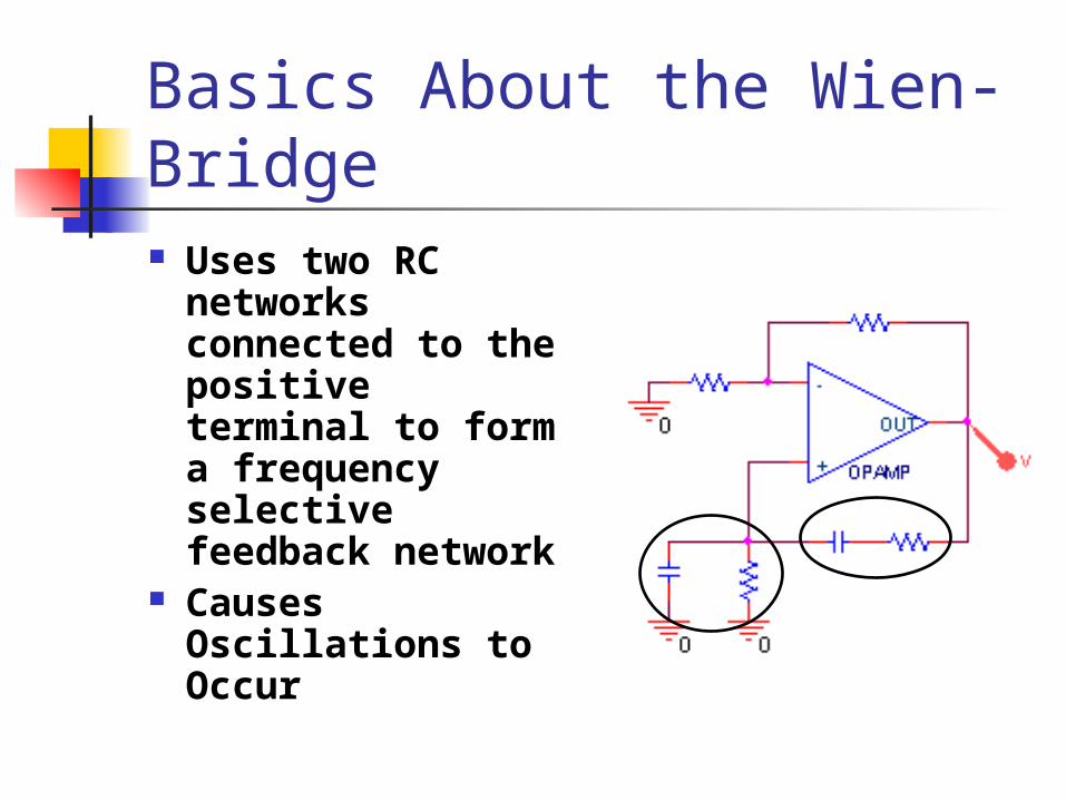
Basics About the Wien-Bridge Uses two RC
networks connected to the positive terminal to form a frequency selective feedback network
Causes Oscillations to Occur
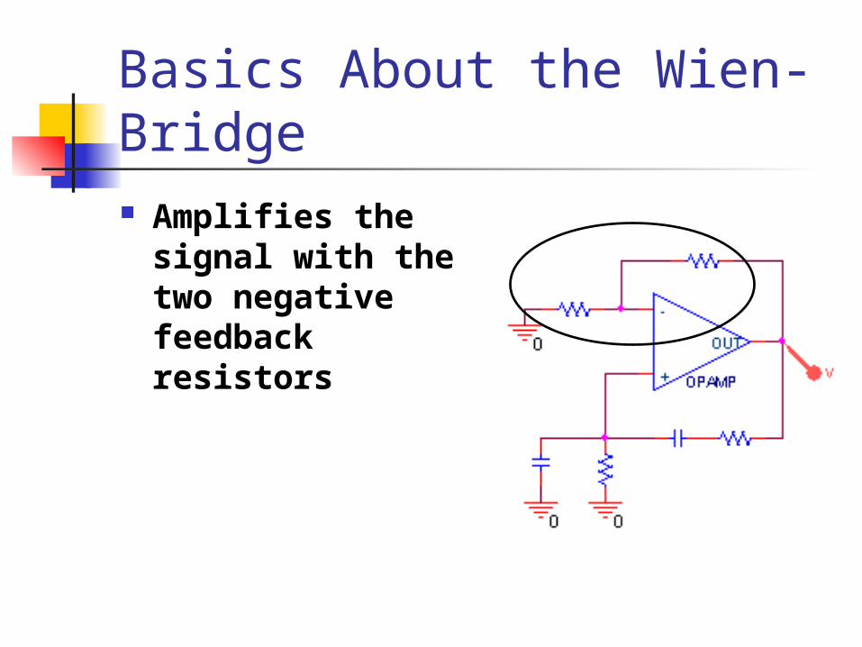
Basics About the Wien-Bridge Amplifies the
signal with the two negative feedback resistors

Modification to Circuit

Analysis The loop gain
can be found by doing a voltage division
Vo s( ) V1 s( )Z 2 s( )
Z 1 s( ) Z 2 s( )
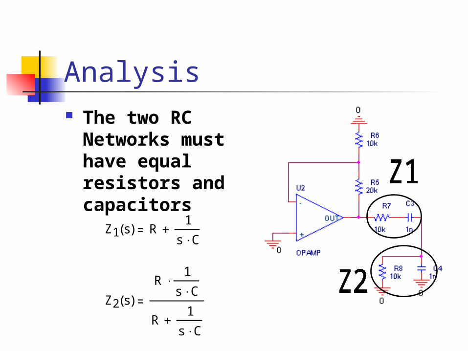
Analysis The two RC
Networks must have equal resistors and capacitors
Z1 s( ) R1
s C
Z2 s( )
R1
s C
R1
s C

Analysis
Operational amplifier gain
GV1 s( )
Vs s( )1
R2
R1
Vo s( ) V1 s( )Z 2 s( )
Z 1 s( ) Z 2 s( )
Need to find the Gain over the whole Circuit: Vo/Vs
Vo s( ) G V s s( )s R C
s2R2 C
2 3 s R C 1
Solve G equation for V1 and substitute in for above equ.

Analysis
T s( )Vo s( )
V s s( )
s R C G
s2R2 C
2 3 s R C 1
We now have an equation for the overall circuit gain
T j j R C G
1 2R2 C
2 3 j R C
Simplifying and substituting jw for s

Analysis
In order to have a phase shift of zero,
1 2R2 C
2 0
This happens at RC When RC, T(j) simplifies to:
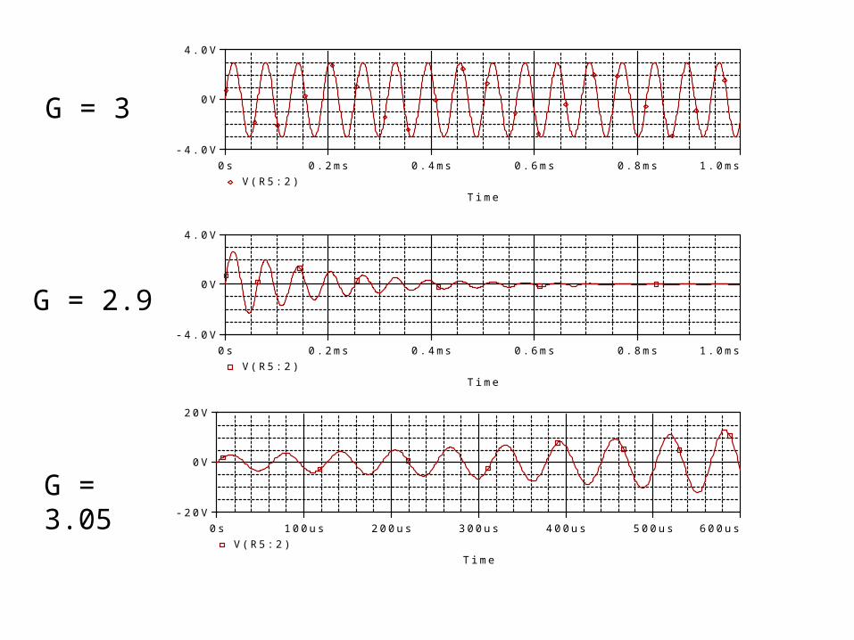
T j G
3
If G = 3, oscillations occur
If G < 3, oscillations attenuate
If G > 3, oscillation amplify
Time
0s 0.2ms 0.4ms 0.6ms 0.8ms 1.0msV(R5:2)
-4.0V
0V
4.0V
G = 3
Time
0s 0.2ms 0.4ms 0.6ms 0.8ms 1.0msV(R5:2)
-4.0V
0V
4.0V
G = 2.9
Time
0s 100us 200us 300us 400us 500us 600usV(R5:2)
-20V
0V
20V
G = 3.05

Ideal vs. Non-Ideal Op-Amp Red is the ideal op-amp. Green is the 741 op-amp.
Time
0s 0.2ms 0.4ms 0.6ms 0.8ms 1.0msV(R1:2) V(R5:2)
-4.0V
0V
4.0V

Making the Oscillations Steady
Add a diode network to keep circuit around G = 3
If G = 3, diodes are off

Making the Oscillations Steady
When output voltage is positive, D1 turns on and R9 is switched in parallel causing G to drop
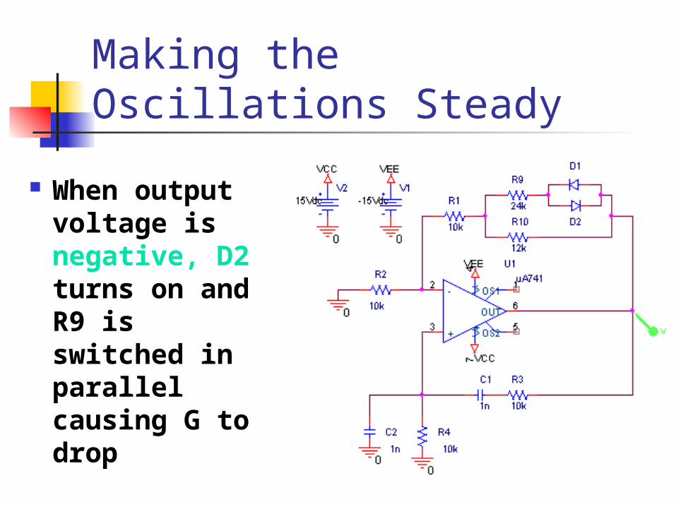
Making the Oscillations Steady
When output voltage is negative, D2 turns on and R9 is switched in parallel causing G to drop

Results of Diode Network
Time
0s 0.2ms 0.4ms 0.6ms 0.8ms 1.0msV(D2:2)
-4.0V
0V
4.0V
With the use of diodes, the non-ideal op-amp can produce steady oscillations.

Frequency Analysis By changing the resistor and
capacitor values in the positive feedback network, the output frequency can be changed.
R 10k C 1nF
1
R C 1 10
5rad
sec
f
2 f 15.915kHz

Frequency Analysis
Frequency
0Hz 10KHz 20KHz 30KHz 40KHzV(D2:2)
0V
2.0V
4.0V(15.000K,2.0539)
Fast Fourier Transform of Simulation

Frequency Analysis Due to limitations of the op-
amp, frequencies above 1MHz are unachievable.

Conclusions No Input Signal yet Produces
Output Oscillations Can Output a Large Range of
Frequencies With Proper Configuration,
Oscillations can go on indefinitely