wifly command reference manual - farnell element14 microchip technology inc. ds50002230b-page 3...
TRANSCRIPT

2014-2015 Microchip Technology Inc. DS50002230B
WiFly Command ReferenceManual

DS50002230B-page 2 2014-2015 Microchip Technology Inc.
Information contained in this publication regarding deviceapplications and the like is provided only for your convenienceand may be superseded by updates. It is your responsibility toensure that your application meets with your specifications.MICROCHIP MAKES NO REPRESENTATIONS ORWARRANTIES OF ANY KIND WHETHER EXPRESS ORIMPLIED, WRITTEN OR ORAL, STATUTORY OROTHERWISE, RELATED TO THE INFORMATION,INCLUDING BUT NOT LIMITED TO ITS CONDITION,QUALITY, PERFORMANCE, MERCHANTABILITY ORFITNESS FOR PURPOSE. Microchip disclaims all liabilityarising from this information and its use. Use of Microchipdevices in life support and/or safety applications is entirely atthe buyer’s risk, and the buyer agrees to defend, indemnify andhold harmless Microchip from any and all damages, claims,suits, or expenses resulting from such use. No licenses areconveyed, implicitly or otherwise, under any Microchipintellectual property rights unless otherwise stated.
Note the following details of the code protection feature on Microchip devices:
• Microchip products meet the specification contained in their particular Microchip Data Sheet.
• Microchip believes that its family of products is one of the most secure families of its kind on the market today, when used in the intended manner and under normal conditions.
• There are dishonest and possibly illegal methods used to breach the code protection feature. All of these methods, to our knowledge, require using the Microchip products in a manner outside the operating specifications contained in Microchip’s Data Sheets. Most likely, the person doing so is engaged in theft of intellectual property.
• Microchip is willing to work with the customer who is concerned about the integrity of their code.
• Neither Microchip nor any other semiconductor manufacturer can guarantee the security of their code. Code protection does not mean that we are guaranteeing the product as “unbreakable.”
Code protection is constantly evolving. We at Microchip are committed to continuously improving the code protection features of ourproducts. Attempts to break Microchip’s code protection feature may be a violation of the Digital Millennium Copyright Act. If such actsallow unauthorized access to your software or other copyrighted work, you may have a right to sue for relief under that Act.
Microchip received ISO/TS-16949:2009 certification for its worldwide headquarters, design and wafer fabrication facilities in Chandler and Tempe, Arizona; Gresham, Oregon and design centers in California and India. The Company’s quality system processes and procedures are for its PIC® MCUs and dsPIC® DSCs, KEELOQ® code hopping devices, Serial EEPROMs, microperipherals, nonvolatile memory and analog products. In addition, Microchip’s quality system for the design and manufacture of development systems is ISO 9001:2000 certified.
QUALITY MANAGEMENT SYSTEM CERTIFIED BY DNV
== ISO/TS 16949 ==
Trademarks
The Microchip name and logo, the Microchip logo, dsPIC, FlashFlex, flexPWR, JukeBlox, KEELOQ, KEELOQ logo, Kleer, LANCheck, MediaLB, MOST, MOST logo, MPLAB, OptoLyzer, PIC, PICSTART, PIC32 logo, RightTouch, SpyNIC, SST, SST Logo, SuperFlash and UNI/O are registered trademarks of Microchip Technology Incorporated in the U.S.A. and other countries.
The Embedded Control Solutions Company and mTouch are registered trademarks of Microchip Technology Incorporated in the U.S.A.
Analog-for-the-Digital Age, BodyCom, chipKIT, chipKIT logo, CodeGuard, dsPICDEM, dsPICDEM.net, ECAN, In-Circuit Serial Programming, ICSP, Inter-Chip Connectivity, KleerNet, KleerNet logo, MiWi, motorBench, MPASM, MPF, MPLAB Certified logo, MPLIB, MPLINK, MultiTRAK, NetDetach, Omniscient Code Generation, PICDEM, PICDEM.net, PICkit, PICtail, RightTouch logo, REAL ICE, SQI, Serial Quad I/O, Total Endurance, TSHARC, USBCheck, VariSense, ViewSpan, WiperLock, Wireless DNA, and ZENA are trademarks of Microchip Technology Incorporated in the U.S.A. and other countries.
SQTP is a service mark of Microchip Technology Incorporated in the U.S.A.
Silicon Storage Technology is a registered trademark of Microchip Technology Inc. in other countries.
GestIC is a registered trademark of Microchip Technology Germany II GmbH & Co. KG, a subsidiary of Microchip Technology Inc., in other countries.
All other trademarks mentioned herein are property of their respective companies.
© 2014-2015, Microchip Technology Incorporated, Printed in the U.S.A., All Rights Reserved.
ISBN: 978-1-63277-737-9

WiFly COMMANDREFERENCE MANUAL
Table of Contents
Chapter 1. Introduction1.1 Overview ...................................................................................................... 111.2 Features ....................................................................................................... 121.3 Supported Access Points ............................................................................. 12
Chapter 2. Getting Started2.1 Prerequisites ................................................................................................ 132.2 Firmware Version Check .............................................................................. 132.3 Common Tasks ............................................................................................ 14
Chapter 3. Features and Settings3.1 Factory Reset ............................................................................................... 213.2 Associating to An Access Point .................................................................... 273.3 Making A Connection To the RN Module ..................................................... 383.4 Connecting the RN Module to a Remote Device .......................................... 383.5 Sending Data To a Remote Host ................................................................. 403.6 Using the HTML Client Feature .................................................................... 463.7 FTP Client Features ..................................................................................... 513.8 Putting the RN Module to Sleep and Waking It ............................................ 533.9 GPIO Functions ............................................................................................ 563.10 Setting Debug Print Levels ......................................................................... 593.11 Using the Real-Time Clock Function .......................................................... 613.12 Time Stamping Packets ............................................................................. 623.13 Soft Access Point (Soft AP) Mode .............................................................. 633.14 Upgrading Firmware ................................................................................... 673.15 Analog Sensor Capability ........................................................................... 74
Chapter 4. Command Reference4.1 Command Syntax ......................................................................................... 774.2 Command Organization ............................................................................... 784.3 Set Commands ............................................................................................. 794.4 Get Commands .......................................................................................... 1324.5 Status Commands ...................................................................................... 1354.6 Action Commands ...................................................................................... 1384.7 File I/O Commands .................................................................................... 144
2014-2015 Microchip Technology Inc. DS50002230B-page 3

WiFly Command Reference Manual
NOTES:
DS50002230B-page 4 2014-2015 Microchip Technology Inc.

WiFly COMMANDREFERENCE MANUAL
Preface
INTRODUCTION
This preface contains general information that will be useful to know before using the WiFly application to access RN modules. Topics discussed in this preface include:
• Document Layout• Conventions Used in this Guide• Recommended Reading• The Microchip Web Site• Development Systems Customer Change Notification Service• Customer Support• Document Revision History
DOCUMENT LAYOUT
This user’s guide provides information for configuring RN modules using the WiFly application, including a command reference, advanced features, and applications. The document is organized as follows:
• Chapter 1. “Introduction” – This chapter introduces the RN modules and provides a brief overview of their features.
• Chapter 2. “Getting Started” – This chapter provides information that is useful when getting started with an RN module.
• Chapter 3. “Features and Settings” – This chapter describes features and settings, including techniques to put the RN module to sleep, wake up, and meth-ods to open a TCP connection when awake.
• Chapter 4. “Command Reference” – This chapter provides information on the commands used to configure RN modules and gives examples.
NOTICE TO CUSTOMERS
All documentation becomes dated, and this manual is no exception. Microchip tools and documentation are constantly evolving to meet customer needs, so some actual dialogs and/or tool descriptions may differ from those in this document. Please refer to our web site (www.microchip.com) to obtain the latest documentation available.
Documents are identified with a “DS” number. This number is located on the bottom of each page, in front of the page number. The numbering convention for the DS number is “DSXXXXXXXXA”, where “XXXXXXXX” is the document number and “A” is the revision level of the document.
For the most up-to-date information on development tools, see the MPLAB® X IDE on-line help. Select the Help menu, and then Topics to open a list of available on-line help files.
2014-2015 Microchip Technology Inc. DS50002230B-page 5

WiFly Command Reference Manual
CONVENTIONS USED IN THIS GUIDE
This manual uses the following documentation conventions:
DOCUMENTATION CONVENTIONS
Description Represents Examples
Italic characters Referenced books MPLAB IDE User’s Guide
Emphasized text ...is the only compiler...
Initial caps A window the Output window
A dialog the Settings dialog
A menu selection select Enable Programmer
Quotes A field name in a window or dialog
“Save project before build”
Underlined, italic text with right angle bracket
A menu path File > Save
Bold characters A dialog button Click OK
A tab Click the Power tab
Text in angle brackets < > A key on the keyboard Press <Enter>, <F1>
Plain Courier New Sample source code #define START
Filenames autoexec.bat
File paths c:\mcc18\h
Keywords _asm, _endasm, static
Command-line options -Opa+, -Opa-
Bit values 0, 1
Constants 0xFF, ‘A’
Italic Courier New A variable argument file.o, where file can be any valid filename
Square brackets [ ] Optional arguments mcc18 [options] file [options]
Curly brackets and pipe character: { | }
Choice of mutually exclusive arguments; an OR selection
errorlevel {0|1}
Ellipses... Replaces repeated text var_name [, var_name...]
Represents code supplied by user
void main (void){ ...}
Notes A Note presents information that we want to re-emphasize, either to help you avoid a common pitfall or to make you aware of operating differences between some device family members. A Note can be in a box, or when used in a table or figure, it is located at the bottom of the table or figure. Note 1: This is a note used in a
table.
Note: This is a standard note box.
CAUTION
This is a caution note.
DS50002230B-page 6 2014-2015 Microchip Technology Inc.

Preface
RECOMMENDED READING
This user’s guide describes how to use the WiFly application to configure an RN module. The RN module-specific data sheets contain current information on the RN module specifications. Additional Microchip documents are available and are recommended as supplemental reference resources. To obtain any of these documents, visit the Microchip web site at www.microchip.com.
RN131 Module Data Sheet (DS70005085), RN171 Module Data Sheet (DS70005084), and RN1723 Module Data Sheet (DS70005224)
Consult these documents for detailed information on the RN131, RN171, and RN1723 modules. Reference information found in this data sheet includes:
• Device pinout and packaging details• Device electrical specifications• List of features included on the RN module
RN131/RN171/RN1723 Evaluation Kits User’s Guide (DS50002183)
This user’s guide describes the RN evaluation boards that are used for demonstrating the capabilities of the RN131, RN171, and RN1723 modules. These RN evaluation boards have the flexibility to connect directly to a PC or laptops through a standard USB interface or to embedded controllers through the serial UART interface. Reference information in this user’s guide includes:
• Overview of the evaluation kit hardware and evaluation board features and components
• Hardware and module configuration
• Sensor interfaces and push button functions
• Evaluation board schematics
PICDEM™ PIC18 Explorer Demonstration Board User’s Guide (DS51721)
This document describes how to use the PICDEM PIC18 Explorer Demonstration Board as a development tool to emulate and debug firmware on a target board. Refer-ence information found in this user’s guide includes:
• Functionality and features• Hardware features• Development board schematics
Explorer 16 Development Board User’s Guide (DS50001589)
This document describes how to use the Explorer 16 Development Board as a development tool to emulate and debug firmware on a target board. Reference information found in this user’s guide includes:
• Functionality and features• Hardware features• Development board schematics
2014-2015 Microchip Technology Inc. DS50002230B-page 7

WiFly Command Reference Manual
THE MICROCHIP WEB SITE
Microchip provides online support via our web site at www.microchip.com. This web site is used as a means to make files and information easily available to customers. Accessible by using your favorite Internet browser, the web site contains the following information:
• Product Support – Data sheets and errata, application notes and sample programs, design resources, user’s guides and hardware support documents, latest software releases and archived software
• General Technical Support – Frequently Asked Questions (FAQs), technical support requests, online discussion groups, Microchip consultant program member listing
• Business of Microchip – Product selector and ordering guides, latest Microchip press releases, listing of seminars and events, listings of Microchip sales offices, distributors and factory representatives
DEVELOPMENT SYSTEMS CUSTOMER CHANGE NOTIFICATION SERVICE
Microchip’s customer notification service helps keep customers current on Microchip products. Subscribers will receive e-mail notification whenever there are changes, updates, revisions or errata related to a specified product family or development tool of interest.
To register, access the Microchip web site at www.microchip.com, click on Customer Change Notification and follow the registration instructions.
The Development Systems product group categories are:
• Compilers – The latest information on Microchip C compilers and other language tools
• Emulators – The latest information on the Microchip in-circuit emulator, MPLAB® REAL ICE™ in-circuit emulator
• In-Circuit Debuggers – The latest information on the Microchip in-circuit debugger, MPLAB ICD 3
• MPLAB X IDE – The latest information on Microchip MPLAB X IDE, the Windows® Integrated Development Environment for development systems tools
• Programmers – The latest information on Microchip programmers including the PICkit™ 3 development programmer
CUSTOMER SUPPORT
Users of Microchip products can receive assistance through several channels:
• Distributor or Representative
• Local Sales Office
• Field Application Engineer (FAE)
• Technical Support
Customers should contact their distributor, representative or field application engineer (FAE) for support. Local sales offices are also available to help customers. A listing of sales offices and locations is included in the back of this document.
Technical support is available through the web site at: http://support.microchip.com
DS50002230B-page 8 2014-2015 Microchip Technology Inc.

Preface
DOCUMENT REVISION HISTORY
Revision A (January 2014)
This is the initial released version of the document.
Revision B (September 2015)
This revision includes the following updates:
• Information specific to the RN1723 module was added throughout the document
• The content was reorganized, which includes text and formatting updates that were incorporated throughout the document
2014-2015 Microchip Technology Inc. DS50002230B-page 9

WiFly Command Reference Manual
NOTES:
DS50002230B-page 10 2014-2015 Microchip Technology Inc.

WiFly COMMANDREFERENCE MANUAL
Chapter 1. Introduction
This reference manual provides information on the commands and features for Microchip products that utilize the WiFly radio module command set. The WiFly radio module is a complete, stand-alone embedded wireless LAN access device. The device has an on-board TCP/IP stack and applications, and in the simplest hardware configuration, requires only four pins: Power, TX, RX, and Ground. Once the initial configuration has been performed, the device automatically accesses a Wi-Fi® network and sends/receives serial data.
Topics covered include:
• Overview• Features• Supported Access Points
1.1 OVERVIEW
This document is applicable to the stand-alone RN131, RN171, and RN1723 modules, as well as Microchip products based on these modules. For example, the RN171XV device incorporates the RN171 module; therefore, all RN171 hardware features apply to the RN171XV. Although there are some differences, the RN131, RN171, and RN1723 modules support the same ASCII command set. Table 1-1 compares the RN module features.
Refer to “Recommended Reading” for information on accessing the RN131, RN171, and RN1723 Data Sheets for information on their hardware differences and for detailed hardware specifications.
TABLE 1-1: COMPARING THE RN131, RN171, AND RN1723 MODULES
Feature RN131 RN171 and RN1723
Output power (PMAX) 18 dBm (fixed) 12 dBm (programmable)
Lowest power 18 dBm 0 dBm (< 100 mA TX current)
On-board antenna Yes No
Accurate sleep timer Yes (32 kHz) No (+/- 10% error)
GPIO pins available 10, GPIO4-13 (GPIO1-3 are not avail-able for use)
14, GPIO1-14
2014-2015 Microchip Technology Inc. DS50002230B-page 11

WiFly Command Reference Manual
1.2 FEATURES
General:
• Fully qualified and Wi-Fi certified 2.4 GHz IEEE 802.11 b/g transceiver
• FCC, CE, IC certified, and RoHS compliant
Ultra-low Power:
• Intelligent, built-in power management with programmable wake-up
• Accepts 3.3V power supply or 2 to 3V battery when using boost regulators
• RN131: 4 µA sleep, 35 mA RX, 210m TX at 18 dBm (TX power is not configurable)
• RN171 and RN1723: 4 µA sleep, 35 mA RX, 185 mA TX at 12 dBm (TX power is configurable)
Antenna Options:
• RN131: On-board ceramic chip antenna and U.FL connector for external antenna
• RN171 and RN1723: RF pad
Hardware:
• 8-Megabit Flash memory and 128 Kbyte RAM, 2 Kbyte ROM, 2 Kbyte battery-backed memory
• General purpose digital I/O pins:
- RN131: 10 GPIO pins
- RN171 and RN1723: 14 GPIO pins
• Eight analog inputs (14 bits, 1.2V)
• Real-time clock for wake-up and time stamping/data logging; automatic sleep and automatic wake-up modes
Network support:
• Supports Soft AP mode and Infrastructure networking modes
• Push button WPS mode for easy network configuration
• On-board TCP/IP stack
• Over the air firmware upgrade (FTP)
• Secure Wi-Fi authentication via WEP, WPA-PSK (TKIP), and WPA2-PSK (AES)
• Configuration over UART or wireless interfaces using simple ASCII commands
• Built-in networking applications: DHCP client, DNS client, ARP, ICMP ping, FTP client, Telnet, HTTP, UDP, and TCP
1.3 SUPPORTED ACCESS POINTS
The RN module should work with any standard Access Point (AP). Microchip has tested the RN modules with Access Points from the following manufacturers:
• Airlink101®
• Apple®
• ASUS• Belkin• Buffalo Networks Inc.• Cisco• D-Link®
• Dynex®
• Linksys• NETGEAR• SMC® Networks• TP-LINK
DS50002230B-page 12 2014-2015 Microchip Technology Inc.
WiFly COMMANDREFERENCE MANUAL
Chapter 2. Getting Started
This chapter provides information for the purpose of getting started with using an RN module. All of the commands discussed in this chapter are described in detail in Chapter 4. “Command Reference”.
Topics in this chapter include:
• Prerequisites• Firmware Version Check
• Common Tasks
2.1 PREREQUISITES
Prior to using an RN module for the first time, readers should be familiar with the information in the “RN131/RN171/RN1723 Evaluation Kits User’s Guide” (DS50002183), which is available from the Microchip website (www.microchip.com). Refer to “Recommended Reading” for information on additional resources.
2.2 FIRMWARE VERSION CHECK
The set of available commands and features for a particular RN module depend greatly on the installed file system contents. Each RN module is loaded with firmware prior to leaving the factory. Consult the Microchip website for firmware information by visiting: http://www.microchip.com/wifi.
The RN module has a file system for storing firmware, as well as configuration files. To view the firmware version, use the ls command. The file size is displayed in sectors and the active boot image is identified in the final message. The WiFly firmware version returned by the ls command is shown in bold type in Example 2-1.
EXAMPLE 2-1: DETERMINING THE FIRMWARE VERSIONFL# SIZ FLAGS 2 88328 3 wifly-FZX-100-r1634i 5 74432 3 web_app-FZX-112 8 46836 3 wps_app-FZX-131 10 66677 3 eap_app-FZX-105 12 51053 0 web_config.html 25 512 0 link.html 26 7268 0 logo.png 28 1060 10 config
2014-2015 Microchip Technology Inc. DS50002230B-page 13

WiFly Command Reference Manual
2.3 COMMON TASKS
This section provides information on the common tasks users may perform when using an RN module, which includes the following topics:
• Configuring the RN Module
• Performing a Factory Reset
• Provisioning Onto and Associating With a Wi-Fi Network
• Sending Data
• Creating a Soft Access Point
• Module Sleep and Wake-up
2.3.1 Configuring the RN Module
The RN module has two modes of operation: Data mode and Command mode.
In Data mode, the RN module can accept incoming connections or initiate outgoing connections. To configure parameters and/or view the current configuration, the RN module must be placed into Command mode.
2.3.1.1 ENTERING COMMAND MODE
By default, the RN module is in Data mode after power-up. Sending the escape sequence of three dollar signs, $$$, causes the RN module to enter Command mode. The three dollar sign ($) characters must be sent in succession with no additional characters before or after. A carriage return (<cr>) or line feed must not be sent after entering $$$ to enter Command mode.
After entering the sequence, the RN module replies with CMD to indicate it is in Command mode. Once in Command mode, the RN module can be configured using simple ASCII commands, with each command ending with a carriage return <cr>. Most valid commands return AOK, with the exception of the RN1723, which returns OK; invalid commands return a ERR description.
To exit Command mode, send an exit command by typing exit following by a <cr>. The RN module responds with EXIT, indicating that it has exited Command mode and has entered Data mode.
2.3.1.2 PARAMETERS
Various parameters can be viewed, such as the SSID, channel, IP address, serial port, and other settings, which can be configured in Command mode.
2.3.1.3 SENDING COMMANDS
Commands must be sent to the RN module through the UART or remotely via Telnet (Telnet can only be used with the RN131 and RN171). When using the UART interface, the communications settings should match the RN module’s stored settings. The default settings are 9,600 baud, 8 bits, No parity, 1 Stop bit, and Hardware Flow Control disabled. Command mode can be entered locally over the UART interface at any time regardless of an active TCP connection.
Note: There is a 250 ms time buffer before and after the $$$ escape sequence. If characters are sent before or after the escape sequence within this 250 ms interval, the RN module treats them as data and passes them over the TCP or UDP socket, and the RN module will not enter Command mode.
Note: Depending on the operating system, Microchip suggests using one of the following terminal emulator applications: Tera Term (Windows) or CoolTerm (Mac).
DS50002230B-page 14 2014-2015 Microchip Technology Inc.

Getting Started
2.3.1.4 AUTOMATIC ACCESS POINT ASSOCIATION
When the RN module powers up, it attempts to automatically associate with the Access Point stored in its configuration settings if the auto-join feature is enabled. In firmware version 4.0 and later, the auto-join feature is disabled by default. Enable it using the ASCII command set wlan join 1.
The auto-associate feature can be disabled (default behavior) using the set wlan join 0 command. This command prevents the RN module from attempting to associate with a network that does not exist.
2.3.2 Performing a Factory Reset
The factory RESET command initializes all of the WiFly module parameters to their factory default values. The default parameters only take effect after the RN module has been rebooted. Refer to 3.1.1 “Default Parameters After Factory Reset” for more information.
To perform a factory reset, first issue the factory RESET command and then reboot the RN module, as follows:
factory RESET // restores default parameter valuesreboot // restart module; default parameters take effect
2.3.3 Provisioning Onto and Associating With a Wi-Fi Network
Before being allowed to communicate on a Wi-Fi network, an RN module must first be provisioned, associated to an Access Point in the network, and have a valid IP address.
There a three common ways to provision and associate an RN module onto a Wi-Fi Network:
• Association using Command mode (via a USB-UART connection)
This is the most commonly used method, which is described in the next section.
• Association through WPS
• Association through a web interface
Note: For information on associating using WPS or a web interface, consult the “RN131/RN171/RN1723 Evaluation Kits User’s Guide” (DS50002183), which is available from the Microchip website (www.microchip.com).
2014-2015 Microchip Technology Inc. DS50002230B-page 15

WiFly Command Reference Manual
2.3.3.1 ASSOCIATION USING COMMAND MODE
To associate using Command mode, perform the following steps:
1. Connect the RN evaluation board to the host (computer) using the USB connection. The green LED should begin blinking.
2. Open the terminal emulator application on the host.
3. Configure the serial port:
a) Locate the COM port that is assigned to the USB cable connected to the RN evaluation kit.
b) In the Terminal Emulator, select the COM port and open the Serial Port Setup dialog and make the following selections:
• Baud rate: 9600
• Data bits: 8
• Parity: None
• Stop bits: 1
• Flow control: None
4. Enter Command mode by sequentially typing $$$ with no other characters before or after (by default, the RN module is in Data mode).
5. In the terminal emulator, type scan and press <Enter> to actively scan for available networks.
6. To associate with the desired AP or network, enter the following commands in the terminal emulator.set wlan ssid <name> // Sets the RN module to automatically
// associate with the specified network// upon boot-up.
set wlan pass <password> // Provides the password to connect to// the specified network
set wlan join 1 // Sets the policy for automatically// associating with Access Points. In// this case, the ‘1’ refers to// associating with an AP that matches// the stored SSID
save // Save the settings to a file named// config (default)
reboot // Force a reboot
DS50002230B-page 16 2014-2015 Microchip Technology Inc.

Getting Started
2.3.4 Sending Data
After the RN module has associated with a network and a valid IP address has been obtained, data can be sent between two RN modules or from an RN module to a server.
Two methods to transfer data are available: TCP and UDP. TCP is the most common method, which is described in this section. Refer to the “RN131/RN171/RN1723 Evaluation Kits User’s Guide” (DS50002183) for information on transferring data through UDP.
Perform the following steps to transfer data using TCP:
1. Configure two RN modules to associate with an AP, as described in 2.3.3 “Provisioning Onto and Associating With a Wi-Fi Network”.
2. Obtain the IP address assigned to each RN module using the get ip command, as shown in the below example. In this example, the IP addresses assigned are 192.168.1.108 and 192.168.1.109.
3. On one of the RN modules, open a socket using the following commands:set ip proto 0x2 // Sets the IP protocol. The parameter
// 0x2 is a bit-mapped register, which// sets the protocol to TCP.
set ip host 192.168.1.109 // Sets the IP address of the remote host
set ip remote 2000 // Sets the port number of the remote host
open // Opens a TCP connection
The terminal emulators on the local host and remote host respond with *OPEN**HELLO* to indicate the connection was opened successfully. Typing into one terminal emulator will display the result on the other terminal emulator.
4. Use the close command to close the socket and disconnect TCP.
Remote Host
Local Host
2014-2015 Microchip Technology Inc. DS50002230B-page 17
WiFly Command Reference Manual
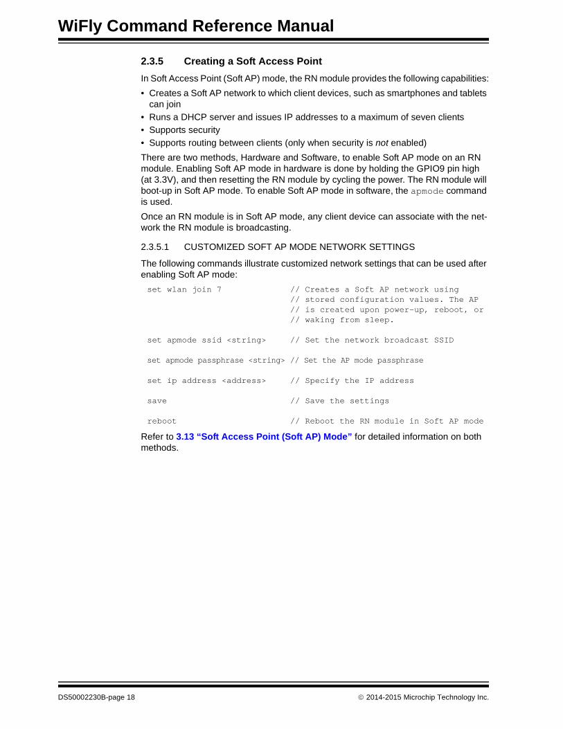
2.3.5 Creating a Soft Access Point
In Soft Access Point (Soft AP) mode, the RN module provides the following capabilities:
• Creates a Soft AP network to which client devices, such as smartphones and tablets can join
• Runs a DHCP server and issues IP addresses to a maximum of seven clients
• Supports security
• Supports routing between clients (only when security is not enabled)
There are two methods, Hardware and Software, to enable Soft AP mode on an RN module. Enabling Soft AP mode in hardware is done by holding the GPIO9 pin high (at 3.3V), and then resetting the RN module by cycling the power. The RN module will boot-up in Soft AP mode. To enable Soft AP mode in software, the apmode command is used.
Once an RN module is in Soft AP mode, any client device can associate with the net-work the RN module is broadcasting.
2.3.5.1 CUSTOMIZED SOFT AP MODE NETWORK SETTINGS
The following commands illustrate customized network settings that can be used after enabling Soft AP mode:
set wlan join 7 // Creates a Soft AP network using// stored configuration values. The AP// is created upon power-up, reboot, or // waking from sleep.
set apmode ssid <string> // Set the network broadcast SSID
set apmode passphrase <string> // Set the AP mode passphrase
set ip address <address> // Specify the IP address
save // Save the settings
reboot // Reboot the RN module in Soft AP mode
Refer to 3.13 “Soft Access Point (Soft AP) Mode” for detailed information on both methods.
DS50002230B-page 18 2014-2015 Microchip Technology Inc.

Getting Started
2.3.6 Module Sleep and Wake-up
There are three methods by which an RN module can be placed into Sleep mode.
• The first method is by using the sleep command through the UART interface
• The second method is to use the sleep timer through the internal RTC interface. In this method, the RN module sleeps for the number of seconds specified in the set sys wake <value> command.
• The third method is to drive the GPIO8 pin high. In this method, the RN module sleeps as soon as the GPIO8 pin is set high. To enable this feature, use the set sys trigger 0x20 command.
2.3.6.1 USING TIMERS FOR SLEEP AND WAKE-UP
WiFly-based RN modules have a set of timers that can be used to both put the RN module to sleep and to wake-up the RN module.
While the RN module is sleeping, it consumes only 4 µA of current. During the time the RN module is awake, it can be made to perform any operation the application requires.
The following set of commands illustrate one method of periodically putting the RN module to sleep for a period of time, and then waking up the RN module:
set wlan ssid my_net // Sets the SSID to connect to after// waking up
set wlan passphrase my_pass // Set the connection passphrase
set sys sleep 30 // Set the RN module to sleep after being// awake for 30 seconds
set sys wake 90 // Wakes the RN module after being in// sleep for 90 seconds
save // Save the settings
reboot // Reboot the RN module
Refer to 3.8 “Putting the RN Module to Sleep and Waking It” for more information.
2014-2015 Microchip Technology Inc. DS50002230B-page 19

WiFly Command Reference Manual
NOTES:
DS50002230B-page 20 2014-2015 Microchip Technology Inc.

WiFly COMMANDREFERENCE MANUAL
Chapter 3. Features and Settings
This chapter describes the RN module’s features and settings, including techniques for placing the RN module into sleep mode and waking up the RN module, as well as methods to open a TCP connection when the RN module is awake. In addition, the UART flow control, alternative GPIO functions, and the real-time clock are described.
The following topics are discussed:
• Factory Reset
• Associating to An Access Point
• Making A Connection To the RN Module
• Connecting the RN Module to a Remote Device
• Sending Data To a Remote Host
• Using the HTML Client Feature
• FTP Client Features
• Putting the RN Module to Sleep and Waking It
• GPIO Functions
• Setting Debug Print Levels
• Using the Real-Time Clock Function
• Time Stamping Packets
• Soft Access Point (Soft AP) Mode
• Upgrading Firmware
• Analog Sensor Capability
3.1 FACTORY RESET
Performing a factory reset on an RN module initializes all of the RN module parameters to their factory default state. This is accomplished by first issuing the factory RESET command, immediately followed by the reboot command.
Internal to the RN module, the factory RESET command loads all of the default param-eter settings into RAM, and then writes these settings into a standard configuration file that the RN module maintains. When the RN module is subsequently rebooted, the settings that were saved in the configuration file take effect.
Microchip recommends that before any major operational modes changes are made to an RN module, that a factory RESET and a reboot command be executed. One such example is switching the RN module from operating as a Soft AP to that of a HMTL client. In this instance, the procedure would be to first factory Reset and reboot the RN module, set it up as a HTML client, save the configuration, and then reboot the RN module a second time.
3.1.1 “Default Parameters After Factory Reset” lists all of the default WiFly settings for an RN module.
2014-2015 Microchip Technology Inc. DS50002230B-page 21

WiFly Command Reference Manual
3.1.1 Default Parameters After Factory Reset
TABLE 3-1: SOFT AP MODE PARAMETERS
TABLE 3-2: BROADCAST PARAMETERS
TABLE 3-3: COMM PARAMETERS
TABLE 3-4: DNS PARAMETERS
TABLE 3-5: FTP PARAMETERS
Parameter Default Value Comment
Beacon 102 Time in milliseconds. For Soft AP mode only.
Probe 5 Number of seconds for beacons before declar-ing Soft AP is lost. For Soft AP mode only.
Reboot 0 For Soft AP mode only.
Parameter Default Value Comment
IP address 255.255.255.255 —
Port 55555 —
Interval 7 Time in seconds.
Backup address 0.0.0.0 —
Backup port 0 —
Parameter Default Value Comment
Close string *OPEN* —
Open string *CLOS* —
Remote string *HELLO* —
Flush size 1420 —
Match character 0 —
Flush timer 10 Time in milliseconds.
Idle timer 0 —
CMD char $ —
Parameter Default Value Comment
IP address 0.0.0.0 —
Name dns1 —
Backup rn.microchip.com —
Lease 8640 For Soft AP mode only.
Parameter Default Value Comment
Server address 0.0.0.0 —
File wifly-GSX-<version>.img Firmware for RN131 modules.
wifly-EZX<version>.img Firmware for RN171 modules.
wifly-FZX<version>.img Firmware for RN1723 modules.
wifly3-<version>.mif Firmware and applications for RN131 modules.
wifly7-<version>.mif Firmware and applications for RN171/RN1723 modules.
User roving —
Password Pass123 —
Dir public —
Timeout 200 —
FTP_mode 0x0 —
DS50002230B-page 22 2014-2015 Microchip Technology Inc.

Features and Settings
TABLE 3-6: IP PARAMETERS
TABLE 3-7: OPTIONAL PARAMETERS
TABLE 3-8: SYSTEM PARAMETERS
TABLE 3-9: TIME SERVER PARAMETERS
Parameter Default Value Comment
DHCP ON ‘1’ equals enabled.
IP address 0.0.0.0 —
Net mask 255.255.255.0 —
Local port 2000 —
Gateway 0.0.0.0 —
Host 0.0.0.0 —
Remote port 2000 —
Protocol 2 TCP server and client.
MTU 1524 —
Flags 0x7 —
TCP mode 0x7 —
Backup 0.0.0.0 —
Parameter Default Value Comment
Device ID WiFly-GSX —
Join timer/WPA timer 1000 —
Replacement char $ 0x24
Format 0x00 —
Password “” No password enforced.
Signal 0 —
Average 5 —
Parameter Default Value Comment
Sleep timer 0 —
Wake timer 0 —
Trigger 0x1 SENS0 pin wakes up the device.
Auto connect 0 —
IOfunc 0x0 No alternate functions.
IOmask 0x20F0 For RN131 modules.
0x21F0 For RN171 and RN1723 modules.
IOvalue 0x0 —
Print level 0x1 Print enabled
Debug Register 0x0 Unused parameter for future development. Leave at default value.
LaunchString web_app —
Parameter Default Value Comment
Enable 0 Disabled.
Server address 64.90.182.55 Fixed to Port 123 - SNTP protocol.
Zone 7 Pacific time zone (USA).
2014-2015 Microchip Technology Inc. DS50002230B-page 23

WiFly Command Reference Manual
TABLE 3-10: UART PARAMETERS
TABLE 3-11: WLAN PARAMETERS
3.1.2 String Variable Sizes
Table 3-12 provides the string variable sizes for the following parameters:
Parameter Default Value Comment
Baudrate 9600 —
Flow 0 Disabled.
Mode 0 —
Cmd_GPIO 0 —
Parameter Default Value Comment
SSID roving1 —
Channel 0 Automatic scan.
External antenna 0 Off - use on-board chip antenna. For RN131 modules only.
Join mode 1 Automatically scan and join based on SSID.
0 Automatic scan and join is disabled.
Authentication mode OPEN —
Mask 0x1FFF All channels.
Rate 12 24 Megabit.
Linkmon 0 —
Passphrase rubygirl —
TX Power 0 Implies 12 dBm. For RN171 modules only.
TABLE 3-12: STRING VARIABLE SIZES
Parameter Type Parameter Value (Bytes)
FTP file 32
user 16
pass 16
dir 32
wlan ssid 32
phrase 64
DNS DNS host name 64
DNA back-up host name 64
comm open 32
close 32
remote 64
deviceid 32
DS50002230B-page 24 2014-2015 Microchip Technology Inc.

Features and Settings
3.1.3 Restoring Default Configuration Settings
3.1.3.1 RESTORING THROUGH SOFTWARE AND HARDWARE
The default factory configuration settings can be restored in software and hardware.
• Software – In Command mode, use the factory RESET command to restore the default settings. This command automatically loads the default settings and exe-cutes a save command. Next, send the reboot command so that the RN module reboots with the default configuration.
• Hardware – Set the GPIO9 pin high on power-up to enable the factory reset func-tion. Then, toggle GPIO9 five times, which restores the configuration to the factory reset. The GPIO9 pin is sampled at approximately 1 Hz; therefore, if a CPU is used to generate the signal, ensure that GPIO9 transitions (high-to-low or low-to-high) for a period of at least one second.
3.1.3.2 USER CONFIGURATION FILE
A user configuration file can be specified and then used to restore a custom set of fac-tory reset settings. For example, if the configuration file named user is found on the RN module’s file system, the RN module reads it as the factory default instead of using the factory hardcoded defaults. If no user configuration file is present, the RN module uses the hardcoded factory defaults.
The user configuration file is created using the save user command, which saves the current configuration settings into a file named user.
Even if a user configuration file exists, enabling and toggling the GPIO9 pin seven times overrides the user settings and restores the RN module to the factory hardcoded defaults. This bypass mechanism allows the factory defaults to be restored in the event that an invalid parameter was saved in the user-defined configuration file.
Issuing the factory RESET command while in Command mode restores the RN module to a factory default state.
3.1.4 Boot-up Timing Values
Table 3-13 shows the boot-up timing values.
Note: The user configuration file can be specified based on firmware version, as follows:
• RN131 and RN171 modules with firmware version 2.45 and later
• RN1723 modules with firmware version 1.0 or later
Note: The RN module must be rebooted or Reset for the new settings to take effect.
TABLE 3-13: BOOT-UP TIMING VALUES
Function Description Time (ms)
Power-up Power-up time from reset high or from the time of power-up to when boot code is loaded from Flash to RAM.
70
Initialization Initialize ECOS. 50
Ready Load configuration and Initialize application. 30
2014-2015 Microchip Technology Inc. DS50002230B-page 25

WiFly Command Reference Manual
Join Associate using channel = 0 (full channel scan, mask = 0x1FFF).
80
Associate using channel = 0 (primary channel scan, mask = 0x421)
15
Associate using channel = X (fixed channel)
5-20
Authentication Authenticate using WPA1 or WPA2 (highly dependent on access point response)
50-250
Acquire IP DHCP obtain IP address (highly dependent on DHCP server response time)
Soft AP Dependent
TABLE 3-13: BOOT-UP TIMING VALUES
Function Description Time (ms)
DS50002230B-page 26 2014-2015 Microchip Technology Inc.

Features and Settings
3.2 ASSOCIATING TO AN ACCESS POINT
Configuring the RN module to make connections involves associating with an Access Point and opening a connection. Before the RN module can be configured over the Wi-Fi link, the RN module must be associated with a network and the network settings must be programmed. Therefore, the best method is to configure the RN module is by using the UART. This section describes how to configure the RN module over the UART using the RS-232 connector or an evaluation board. For this mode, open a ter-minal emulator on the COM port associated with the RN module. The default baud rate is 9,600, 8 bits, and No parity.
3.2.1 Associate With an Access Point
From within the terminal window, place the RN module into Command mode by typing $$$. The RN module responds with CMD, indicating that it is in Command mode. Type show net to display the current network settings, as shown in Figure 3-1.
FIGURE 3-1: DISPLAY CURRENT NETWORK SETTINGS
Find all available networks with the scan command, as shown in Figure 3-2.
FIGURE 3-2: FIND AVAILABLE NETWORKS
To connect to an open network, use the join command to associate with the access point. The scan list in Figure 3-2 shows that roving1 is an open access point. Type join roving1 (or join # 1) to associate with the network, as shown in Figure 3-3.
CMDshow netSSid=TheLoftChan=6Assoc=OKDHCP=OKTime=FAILLinks=1<2.03>
CMDscan<2.03>SCAN:Found 6Num SSID Ch RSSI Sec MAC Address Suites 1 roving1 01 -64 Open 00:1c:df:4f:45:9e 104 4 2 NETGEAR 01 -58 Open 00:22:3f:6b:95:42 104 0 3 07FX12018434 06 -73 WEP 00:18:3a:7e:71:d7 1104 0 4 TheLoft 06 -51 WPA2PSK 00:0c:41:82:54:19 AESM-AES 1100 0 5 airlink-11 11 -53 WPAv1 00:18:02:70:7e:e8 TKIPM-TKIP 3100 ac 6 sensor 11 -52 Open 00:1c:df:cc:aa:d8 100 1
2014-2015 Microchip Technology Inc. DS50002230B-page 27

WiFly Command Reference Manual
FIGURE 3-3: JOIN THE NETWORK
If the access point is secure, the passphrase must be set prior to issuing the join command. The RN module attempts to inquire and determine the access point’s security protocol which means the authentication mode does not need to be set. To set the WPA passphrase use the set wlan passphrase <string> command. For WEP, set the key using the set wlan key <value> command.
Once the RN module has joined the network successfully, it stores the access point’s SSID. The SSID and the passphrase can be saved to the configuration file so that the RN module can associate with the access point each time it boots.
3.2.2 Wi-Fi Protected Setup (WPS)
Wi-Fi Protected Setup (WPS) protocol created by the Wi-FI Alliance is a standard for easy and secure establishment of a wireless home network.
The goal of the WPS protocol is to simplify the process of configuring security on wireless networks. The protocol is meant to allow home users who know little of wireless security and may be intimidated by the available security options to configure Wi-Fi Protected Access, which is supported by most Wi-Fi certified devices that are available for purchase today.
The most common mode of WPS is the Push Button (PBC) mode, in which the user simply pushes a button on both the access point and the wireless client (e.g., the RN module), as shown in Figure 3-4.
FIGURE 3-4: PUSH BUTTON WPS
<2.03> join roving1Auto-Assoc roving1 chan=1 mode=OPEN SCAN OK
<2.03> Associated!DHCP in 1ms: Renew: 86400 sIF is UPDHCP=ONIP=10.20.20.62:2000NM=255.255.255.0GW=10.20.20.20HOST=0.0.0.0:2000PROTO=2MTU=1460bind=-10listen FAIL
DS50002230B-page 28 2014-2015 Microchip Technology Inc.

Features and Settings
Depending on the firmware version, the RN module supports the WPS feature.
FIGURE 3-5: CONFIRMING WPS APPLICATION INSTALLATION
Note: Use the ls command to confirm whether the RN module supports the application, as shown in Figure 3-5.
2014-2015 Microchip Technology Inc. DS50002230B-page 29

WiFly Command Reference Manual
3.2.2.1 LAUNCHING A WPS APPLICATION
There are two ways to run a WPS function:
• Using the run wps command in the console
• Using GPIO9
To run a WPS function using the factory reset (GPIO9) mode:
1. Enable the WPS function on GPIO9 using the set sys launch wps_app command. WPS on GPIO9 is disabled by default to avoid accidentally running the WPS function.
2. The WPS application is started when GPIO9 asserted.
When the WPS application launches, it negotiates the SSID and passphrase with the Soft AP and reboots the RN module to associate with the WPS-enabled access point.
By default, during the WPS process, the RN module prints messages on the UART as it scans channels, detects access points, and tries to complete WPS. These messages are disabled using the set sys print 0 command.
Note: Depending on the firmware version, if the GPIO9 pin is high, the RN module boots in Soft AP mode. Care must be taken to drive GPIO9 low before the RN module reboots. A good indicator is the red LED on the RN171 evaluation board. When this LED flashes, indicating the RN module is scanning for a WPS-enabled access point, the GPIO9 pin should be driven low.
DS50002230B-page 30 2014-2015 Microchip Technology Inc.

Features and Settings
3.2.3 Configuration Web Server
This section describes how to use the RN module’s configuration Web server to associate an RN module to an access point.
RN modules can operate in one of two modes: Infrastructure and Soft AP.
• Infrastructure mode
In this mode, the RN module can join a network created by an access point.
• Soft AP mode
In this mode, the RN module behaves as an access point with limited functionality.
A key challenge when using any embedded device in Infrastructure mode is to provision it so that it can associate with a Soft AP. This process requires storing the Soft AP’s settings, such as the SSID and passphrase, in the embedded device.
Embedded Wi-Fi modules can be configured or provisioned to join an infrastructure network in several ways:
• Sending ASCII commands to the RN module over a UART
• Sending ASCII commands remotely while the RN module is in Soft AP mode
• Using Wi-Fi Protected Setup (WPS)
• Sending commands to the RN module remotely using a web interface
3.2.3.1 USING THE CONFIGURATION WEB SERVER
Configuring the embedded RN module to associate with an Soft AP in Infrastructure mode involves the following process:
1. Start the RN module’s configuration Web Server.
2. Connect the client device (i.e., PC, smartphone, tablet, etc.) to the RN module’s Soft AP network.
3. Access the RN module’s configuration web page from the client device’s web browser.
4. Save the settings (SSID and passphrase) in the web browser and exit.
Note: Depending on the firmware version, the Web Server application is available for use in configuring the RN module, as follows:
• RN131 and RN171 modules with firmware version 4.0 and later
• RN1723 modules with firmware version 1.0 or later
2014-2015 Microchip Technology Inc. DS50002230B-page 31

WiFly Command Reference Manual
3.2.3.1.1 Start the Configuration Web Server
The Web Server can be enabled in one of two ways: hardware or software. When the configuration Web Server is started, it creates a Soft AP network with the settings shown in Table 3-14.
3.2.3.1.2 Starting the Configuration Web Server in Hardware
The Web Server can be started through hardware using GPIO9. To use GPIO9, specify that the web application should launch using the command set sys launch_string web_app (default configuration).
With the launch string set, drive the GPIO9 pin high any time after power-up to start the Web Server. The RN module creates a Soft AP network with the parameters previously described in Table 3-14.
3.2.3.1.3 Starting the Configuration Web Server in Software
If GPIO9 is not accessible using a push button or a jumper, an embedded microcontroller can start the configuration Web Server mode in software using the command run web_app. This command runs the configuration Web Server application and creates a Soft AP network to which devices can join and configure the RN module from a web browser.
TABLE 3-14: SOFT AP NETWORK SETTINGS
Setting Soft AP Mode Default
SSID • WiFly-GSX-XX (RN131 module)• WiFly-EXZ-XX (RN171)• WiFly-FXZ-XX (RN1723)Where ‘XX’ is the last byte of the RN module’s MAC address.
Channel 1
DHCP server Enabled
IP address 192.168.1.1
Netmask 255.255.255.0
Gateway 192.168.1.1
Note: The Soft AP network’s SSID uses the RN module’s device ID parameter. If the device ID parameter is changed using the set opt device_id <string> command, the RN module uses this new device ID as the Soft AP network’s SSID. The device ID parameter is not set to a default if a factory reset is performed.
Note 1: Do not drive GPIO9 high upon power-up. Doing so starts Soft AP mode and does not launch the Web Server.
2: When using an evaluation kit, GPIO9 is accessible using a jumper or push button.
DS50002230B-page 32 2014-2015 Microchip Technology Inc.

Features and Settings
3.2.3.2 STATUS LEDS IN CONFIGURATION WEB SERVER MODE
The status LEDs provide a visual indication of the RN module’s state while using the configuration Web Server feature, as shown in Table 3-15.
3.2.3.3 USING THE WEB SERVER TO CONFIGURE THE RN MODULE
This section describes how to use the Web Server to configure the RN module with the SSID and passphrase of the Soft AP. The example uses the Internet Explorer web browser running on a Windows 7 personal computer; however, the same concepts apply to any device with a Wi-Fi interface, such as an iPhone, Android smartphone, tablet, or PCs, running a web browser such as Chrome, Firefox, or Safari.
To configure the RN module using a web browser, perform the following steps:
1. Associate a PC to the RN module’s Soft AP network, as shown in Figure 3-6.
FIGURE 3-6: MODULE’S NETWORK NAME
2. Launch a web browser.
TABLE 3-15: STATUS LEDS
Event LED Action
Launch Soft AP mode Red, green Blink alternately
Yellow, blue Off
Client associated with the Soft AP network
Green Solid on
Yellow Blinks fast (twice per second)
Web browser launched on the client
Blue Solid on
Green Solid on
Yellow Blinks fast (twice per second)
2014-2015 Microchip Technology Inc. DS50002230B-page 33

WiFly Command Reference Manual
3. Type http://config to go to the home page of the Web Server running on the RN module. The page has two tabs displayed by default, as shown in Figure 3-7:
• Network Configuration
This tab is used to set the Soft AP’s SSID and passphrase.
• Information
This tab displays the following information about the RN module:
- RN module’s MAC address
- Module type (RN131 or RN171/RN1723)
- List of files on the file system
- Battery strength
FIGURE 3-7: NETWORK CONFIGURATION TAB
DS50002230B-page 34 2014-2015 Microchip Technology Inc.

Features and Settings
4. Select the Network Configuration tab, as shown in Figure 3-7. The RN module’s network settings (SSID and passphrase) are configured using this tab. Configure these settings as follows:
a) Enter the network’s SSID in the Access Point SSID field.Alternatively, click Refresh List. The RN module scans for networks and dis-plays a list of found networks. Select your network from the Available Access Points list or enter it in the Access Point SSID box. Clicking an SSID displays a drop-down menu with more information about that network, such as channel, RSSI, security mode (WEP, WPA, WPA2), capabilities, WAP configurations, WPS configuration, and the Soft AP’s MAC address (also called BSSID). If the desired access point is not in the list, click Refresh List to scan again.
b) Enter the Soft AP’s security passphrase in the Passphrase field.
c) (Optional) The RN module uses DHCP by default. To assign the RN module a static IP, turn off the Check to enable DHCP option and enter the static IP, subnet mask, and gateway.
d) Once the network settings have been configured, click Save Configuration to save the settings to the RN module.
5. Exit the Web Server by clicking Exit Web Configuration App. The RN module reboots in Infrastructure mode and joins the wireless network.
Note: If the wireless network is hidden (i.e., not broadcasting an SSID), it does not display in the scan output. In this case, the SSID must be manually entered.
2014-2015 Microchip Technology Inc. DS50002230B-page 35

WiFly Command Reference Manual
3.2.3.4 USING THE ADVANCED TABS
Turning on the Display Advanced Tabs option (bottom right corner of the application window) opens the Terminal and Module Configuration tabs.
3.2.3.4.1 Terminal Tab
Click the Terminal tab (see Figure 3-8). In this tab, ASCII commands can be issued to configure any of the RN module’s parameters. The Web Server includes a Help utility that guides the user through the RN module configuration. To use this feature, type help in the terminal.
FIGURE 3-8: TERMINAL TAB
DS50002230B-page 36 2014-2015 Microchip Technology Inc.

Features and Settings
3.2.3.4.2 Module Configuration Tab
Click the RN module Configuration tab (see Figure 3-9). In this tab, the RN module’s frequently used parameters such as device ID, UART baud rate, and flow control are configured. Other parameters can be configured using ASCII commands in the Terminal tab.
FIGURE 3-9: MODULE CONFIGURATION TAB
3.2.3.5 WEB SERVER TIMERS
The application includes two timers to ensure that the Web Server runs smoothly:
• Idle timer• Browser disconnect timer
3.2.3.5.1 Idle Timer
The idle timer ensures that the client associated with the RN module’s Soft AP network is not lost or unresponsive. If there is no interaction between the configuration Web Server and the client’s web browser for five minutes (default value), the RN module reboots to the boot image. To restart the configuration Web Server, it must be started in software or hardware as described in 3.2.3.1.1 “Start the Configuration Web Server”.
The time-out defaults to five minutes (300 seconds) and is configurable via the following command:
set comm idle <seconds>
3.2.3.5.2 Browser Disconnect Timer
This timer is used to recover from an unexpected situation in which the configuration Web Server on the RN module becomes unresponsive to the requests sent out by the web browser.
The web browser periodically sends requests to the configuration Web Server. If the RN module does not receive a request within 60 seconds, it assumes that the configu-ration Web Server has become unresponsive and it reboots itself into configuration Web Server mode. Then, the device must be reassociated with the RN module’s Soft AP network and the web page must be refreshed.
2014-2015 Microchip Technology Inc. DS50002230B-page 37

WiFly Command Reference Manual
3.3 MAKING A CONNECTION TO THE RN MODULE
To connect to the RN module from a remote device, open an IP socket and connect to the RN module’s IP address. Telnet can be used to test the connection by typing open <address> <port> in a Telnet window. After the connection is open, characters can be typed in the UART window and viewed in the Telnet window or vise versa.
EXAMPLE 3-1: OPEN A CONNECTION
To make a connection from the RN module the server application’s IP address and port number must be known. A COM port redirector is a simple program that can be used to test this functionality. This software opens an IP port and transfers all data it receives to a specified COM port on a user’s personal computer. A free COM port redirector program for Windows is available from Pira at: http://www.pira.cz/eng/piracom.htm.
In the COM port redirector program, note the IP address of the personal computer by typing the ipconfig command in the Microsoft Command Window. From the terminal emulator, place the RN module into Command mode, and then type the open <address> <port> command. The server reports that the connection is open and characters can be typed into the UART window and viewed on the server window or vice versa.
3.4 CONNECTING THE RN MODULE TO A REMOTE DEVICE
Some applications require the RN module to connect to a remote server, send data, and then disconnect automatically upon power-up (or wake-up). The RN module can be configured to perform this functionality automatically.
Set the network SSID and security, and set auto-join to ‘1’. When the RN module wakes up or is powered on, the auto-connect timer causes the RN module to attempt a con-nection to the stored remote IP address and port. The sleep timer does not decrement while this connection is open, and the idle timer does not decrement while data is flow-ing. When data stops for five seconds, the connection is closed, and the sleep timer places the RN module in Deep Sleep mode. The wake timer begins the cycle again one minute later.
EXAMPLE 3-2: AUTOMATIC CONNECTION
open 10.20.20.62 2000 // Open the Host (see Figure 3-3)
set ip host <address> // Set up the IP address of the// remote machine’s IP address
set ip remote_port <value> // Set up the IP port of the// remote machine
set sys autoconn 1 // Automatically connect when readyset com idle 5 // Disconnect after 5 seconds with no
// data activityset sys sleep 2 // Sleep 2 seconds after the
// connection is closedset sys wake 60 // Wake up after 1 minute of sleepset uart mode 2 // Use UART data trigger mode, which
// causes the RN module to make a // TCP/HTTP connection upon incoming // UART data
DS50002230B-page 38 2014-2015 Microchip Technology Inc.

Features and Settings
3.4.1 Controlling Connections using GPIO5 and GPIO6
The GPIO5 pin can be used to control the TCP connection. After configuring the pin with the set sys iofunc command, the RN module attempts to connect to the stored IP address and port when GPIO5 goes high and disconnects when GPIO5 goes low.
Similarly, the connection status can be monitored by reading the GPIO6 pin. When it goes high, the connection is open, and when it goes low, the connection is closed. Use the command set sys iofunc command to enable GPIO6.
EXAMPLE 3-3: USE GPIO5 AND GPIO6 TO CONTROL CONNECTIONS
3.4.2 Using DNS Settings
The RN module contains a built-in DNS client. If the IP address of the Host is not specified (i.e., it is set to 0.0.0.0), the RN module uses the DNS protocol. When the Host name is set using the set dns name <string> command, the RN module automatically attempts to resolve the Host address. When the address is resolved, the RN module automatically connects.
Use the lookup <string> command to manually look up a Host’s IP address, where <string> is the host name.
EXAMPLE 3-4: USE DNS
3.4.3 Using the Back-up IP Address/Connect Function
The RN module contains a feature for auto-retry and redundancy. If the host’s first IP address connection fails, the RN module uses the back-up IP (if set). If this fails (or is not set), the RN module uses the first DNS name. If this fails (or is not set), the RN module uses the back-up DNS name (if set).
EXAMPLE 3-5: SET THE BACK-UP IP ADDRESS
EXAMPLE 3-6: SET THE BACK-UP DNS NAME
set sys iofunc 0x20 // Enable GPIO5 set sys iofunc 0x40 // Enable GPIO6
set dns name my_server // Set the DNS Host name to my_server
set ip backup <address> // Set the back-up IP address
set dns backup <string> // Set the back-up Host name
2014-2015 Microchip Technology Inc. DS50002230B-page 39

WiFly Command Reference Manual
3.5 SENDING DATA TO A REMOTE HOST
3.5.1 Controlling Connections with GPIO Pins
In embedded applications it is useful to monitor and control the status of the TCP/IP connection. To monitor and control the RN module’s connection status, enable the alternate function of GPIO4-GPIO6. Using the alternate function for these GPIO pins, the RN module connects to the stored remote Host IP address and port when GPIO5 is driven high, and disconnects when driven low. The TCP/IP connection status can be monitored by reading GPIO6; it is high when connected, and low when not connected.
To configure the RN module to connect using GPIO5 and GPIO6, use the following commands:
set ip host <address> // Set the IP address of the remote hostset ip remote <value> // Set the IP port of the remote hostset sys iofunc 0x70 // Set alternate function for GPIO4-GPIO6save // Store configurationreboot // Reboot the RN module
After executing these commands, run the application or other software on the remote Host that opens and listens on the specified port. Then, connect GPIO5 to the embed-ded processor or other control signal. When GPIO5 is driven high, the RN module attempts to connect. When GPIO5 is driven low, the connection is closed.
If the connection to the remote Host is successful, GPIO6 goes high. If the COMM OPEN and REMOTE strings are set, the UART displays *OPEN* and the remote Host displays *HELLO*. Figure 3-10 shows the process of controlling connections with the GPIO pins.
FIGURE 3-10: CONTROLLING CONNECTIONS WITH THE GPIO PINS
WARNING
Do not drive the GPIO pin with more than 3.3V DC or permanent damage to the RN module will occur.
DS50002230B-page 40 2014-2015 Microchip Technology Inc.

Features and Settings
3.5.2 System and Auto-Connect Timers
The RN module uses a Real-Time Clock (RTC) to generate timers. The RTC is active even when the RN module is asleep, allowing the RN module to be put to sleep and woken based on timer intervals.
The RN module has the following timers:
• Sleep timer
This timer is used to put the RN module to sleep. It is a 32-bit number, which corresponds to a maximum 1.19 million waking hours. The sleep timer is set with the set sys sleep <value> command, where <value> is a decimal number representing seconds.
• Wake timer
This timer is used to wake the RN module. It is a 22-bit number, which corresponds to a maximum sleep time of 1,165 hours. The wake timer is set with the set sys wake <value> command, where <value> is a decimal number representing seconds.
• Auto-connect timer
This timer is used to automatically open a TCP connection.
• Idle timer
This timer is used to automatically close a TCP connection.
The sleep and wake timers are responsible for putting the RN module to sleep and waking up the RN module. If the sleep timer is enabled, the RN module automatically goes into Deep Sleep Low-Power mode once the timer counts down to zero. The sleep timer is disabled if the RN module has an IP connection or is in Command mode.
For example, to wake the RN module, join a network, and have the RN module available to accept TCP connections for 30 seconds every two minutes, the timers would be set, as shown in Example 3-7.
EXAMPLE 3-7:
Figure 3-11 shows the transitions between the sleep and awake state based on the sleep and wake timer settings in the previous example.
FIGURE 3-11: SLEEP AND AWAKE STATE TRANSITIONS
set wlan ssid my_net // Set the Host nameset wlan passphrase my_pass // Set the passphraseset sys sleep 30 // Module sleeps after being awake
// for 30 secondsset sys wake 90 // Module wakes after sleeping for
// 90 secondssave // Save the settingsreboot // Reboot the RN module
Awake State
Sleep State
Sleep Timer30 s
Wake Timer90 s
Sleep Timer30 s
2014-2015 Microchip Technology Inc. DS50002230B-page 41

WiFly Command Reference Manual
3.5.3 Using TCP To Send Data
After the RN module wakes, a TCP connection to a remote host can be opened in a number of ways, as described in Table 3-16. The remote Host is set using the following commands:
set ip host <address> // Sets the IP address of the Host
OR
set dns name <string> // Sets the URL of the Host
set ip remote <value> // Sets the port number on which the // host is listening
save // Save the settings in the config file reboot // Reboot the RN module so that the
// settings take effect
3.5.3.1 TCP CONNECTION TIMERS
The TCP connection timers control when the RN module opens or closes a socket.
3.5.3.1.1 Opening a TCP Connection
In TCP Client mode, the auto-connect timer controls the establishment of a socket con-nection. When set, the device periodically attempts to establish a connection when the timer expires.
The set sys autoconn <value> command causes the RN module to connect to the Host periodically. The timer <value> determines how often to connect to the stored remote host. If set to ‘1’, the RN module makes one attempt to auto-connect upon power-up. If set to ‘2’ or higher, auto-connect reopens the connection after the connection is closed. The default value of ‘0’ disables the timer.
TABLE 3-16: METHODS OF CONNECTING TO A REMOTE HOST
Method Type Description
Auto connect Internal RTC timer Connect to the Host at specific time intervals based upon the set sys autoconn <value> command setting.
Open UART In Command mode, issue the open command.
Connect on UART data
UART mode 2 This mode is designed for the HTML client feature. Use the set uart mode 2 command to connect the to Host automatically when UART data is received.
GPIO5 Alternative GPIO functions
Set the alternative functions for GPIO4, GPIO5, and GPIO6, as described in Section 3.13.2.6 “Alternative GPIO4/GPIO5/GPIO6 Functions”. Set GPIO5 high to trigger a TCP connection, and low to disconnect.
Note: The remote Host’s IP address and port number must be specified in the RN module’s configuration file for the auto-connect timer to work.
DS50002230B-page 42 2014-2015 Microchip Technology Inc.

Features and Settings
3.5.3.1.2 Closing the TCP Connection
The RN module supports a disconnect timer in both TCP Client and Server mode (default mode). This timer can be used to close a TCP connection automatically after a specified number of seconds of no transmit or receive data. To set the disconnect timer, use the set comm idle <value> command, where <value> is the number of seconds. The default comm idle timer value is ‘0’, which means the RN module never disconnects when idle.
For example, to close the TCP connection after 5 seconds of inactivity, use the set comm idle 5 command.
3.5.4 Using UDP To Send Data
UDP is a connectionless protocol where there is no initial handshaking between the hosts to set up the UDP connection, and the receiver does not send an acknowledg-ment when it receives UDP packets. Therefore, UDP is an unreliable protocol because there is no guarantee that the data will be delivered correctly. However, because it is connectionless, UDP is suited for applications that cannot tolerate too much latency, but can tolerate some errors in the data, such as video transmission.
To use UDP with the RN module, the UDP protocol must be enabled using the set ip proto 1 command. The remote host’s IP address and the local and remote port num-ber to be used for UDP communications must also be specified. Example 3-8 and Example 3-9 show the commands to enable UDP data transfer.
EXAMPLE 3-8: ASSOCIATE WITH A NETWORK
EXAMPLE 3-9: SET UP THE PROTOCOL AND PORT NUMBER
Because UDP is a connectionless protocol, data begins flowing as soon as the RN module is rebooted. Unlike TCP, it is not necessary to send a set comm open command to establish the connection. The RN module acts like a data pipe where the UART data is sent over the Wi-Fi link via the UDP protocol (in this case) and the data coming from the Wi-Fi link (via UDP protocol in this case) is sent to the UART.
set wlan ssid <string> // Set the network nameset wlan phrase <string> // Set the passphrase for WPA & WPA2 modes
set ip proto 1 // Enable UDP as the protocolset ip host <address> // Set the IP address of the remote Host set ip remote <value> // Set the remote port on which the Host listensset ip local <value> // Set the port number on which the RN module
// listenssave // Save the settings in the config filereboot // Reboot the RN module
Note: Attempting to send data by typing characters on the keyboard or if the microcontroller is not sending data fast enough, the RN module sends out packets with fewer data bytes. To avoid this issue, set the flush timer to a higher value. By default, it is set to 10 ms. Forwarding can be disabled based on the flush timer (set comm time 0) or set it to a higher value (set comm time 2000).
2014-2015 Microchip Technology Inc. DS50002230B-page 43

WiFly Command Reference Manual
3.5.4.1 UDP AUTO-PAIRING
With the UDP auto-pairing feature, the RN module temporarily stores the Host IP address of the first remote device that sends a UDP packet to the RN module. This Host IP address is stored in the RN module’s RAM, which is cleared when the RN mod-ule sleeps or power cycles. This feature allows the RN module to echo to any client that sends a UDP packet.
EXAMPLE 3-10: TURN ON AUTO PAIRING
3.5.4.2 UDP RETRY
This feature adds a level of reliability to the UDP protocol without adding the complete overhead of the TCP protocol. When enabled, the RN module waits for a response on every UDP packet that is sent (any UDP packet coming back in). If the RN module does not receive the response packet by approximately 250 ms, the same UDP packet is sent out. This process continues until either a UDP response is seen or a new UDP packet is sent from the RN module and is acknowledged.
Refer to “set ip flags <mask>” for information on the bit to set to enable this feature.
3.5.4.3 UDP BROADCAST
The RN module can be set up to generate UDP broadcast packets automatically, which is useful for the following reasons:
• Some access points disconnect devices that are idle. UDP broadcast informs the access point that the RN module is alive and wants to stay associated.
• Applications can use this feature to automatically discover and configure the RN module. If an application is listening for the UDP broadcast, a number of useful parameters are present in the package that can be used for auto-discovery. For example, the RN module’s IP address and port number are part of the packet, thus an application can connect to the RN module and remotely configure it.
• The associated access point’s MAC address, channel, and RSSI value are also available in this packet, enabling a simple location and tracking function.
By default, the RN module sends out a UDP broadcast to 255.255.255.255 on port 55555 at a programmable interval. The broadcast address, port, and interval are set using the set broadcast commands.
set ip host 0.0.0.0 // Set the IP Host to 0.0.0.0set ip flags 0x40 // Set the IP flags to 0x40
Note: The RN module’s sensor data out can be sent via UDP broadcast. The analog-to-digital converter is 14 bits on a 400 mV signal, which translates to about 24 microvolts (0x61A80 in hex). Using the show q command in Command mode, the RN module displays the raw readings. However, for HTTP web posting and UDP broadcast packets, the RN module shifts the reading by four bits (which is a divide by 16) resulting in a 16-bit number. Therefore, to obtain the actual voltage sampled, the 16-bit number must be shifted left by four bits to get the number of microvolts. If the value in millivolts is known (and high accuracy is not needed), right shift by another six bits, which is the same as dividing by approximately 1K.
DS50002230B-page 44 2014-2015 Microchip Technology Inc.

Features and Settings
The packet is 110 bytes of data, as shown in Figure 3-12.
FIGURE 3-12: UDP BROADCAST PACKET BYTE FORMAT
3.5.4.4 UDP SLEEP AND CONNECTION TIMERS
In UDP Only Protocol mode (set with the set ip proto 1 command), the auto-connect timer is used as an auto-sleep timer. When the RN module begins to transmit the first UDP data packet, this timer begins counting down. When it reaches zero, the RN module sleeps.
The UDP auto-sleep timer can be set using two commands: set sys autosleep and set comm timer. The timer interval is a product of the auto-sleep value and the com-munication flush timer (in ms). The timer is decremented every “product” millisecond.
For example, for a UDP sleep timer of 40 ms, use the following commands:
set sys autosleep 4 // Set auto-sleep value to 4set comm timer 10 // Set comm timer to 10 ms (default value)
The resulting UDP sleep timer is four times 10 ms or 40 ms. To achieve the same effect, set autosleep = 2 and comm timer = 20.
Note: To add sensor data to the UDP broadcast message, the sensors must be enabled using the sensor mask. The set q sensor 0xff command enables all sensors.
0 - 5 6 7 8 - 9 10 - 13 14 - 15 16 - 17 18 - 31 32 - 59 60 - 91 92 - 93 94 - 110
Version String with Date Code (2 Bytes) Programmable
ASCII Time (1 ytes)
GPIO Pin Value (2 ytes)
Access Point’s MAC Address (6 ytes)
Channel (1 yte)
RSSI (1 yte)
Local TCP Port (2 ytes)
RTC Value, MSB to LSB (4 ytes)
Battery Voltage in mV, e.g., 2755 (2 ytes)
Position
Sensor 0 - 7 Voltage Readings Enabled with (16 Bytes)
Device ID Set with (32 ytes)
Note: It is recommended to use a minimum value of 2 (when the default flush time is 10 ms) to ensure that the UDP packet is transmitted. For larger packets, the value should be increased.
2014-2015 Microchip Technology Inc. DS50002230B-page 45

WiFly Command Reference Manual
3.6 USING THE HTML CLIENT FEATURE
The RN module has a built-in HTML client. When enabled, the RN module can get or post data to a Web Server. For example, the HTML client can be used to post serial and/or sensor data to the host Web Server. This feature makes it possible to provide Wi-Fi capabilities to applications such as GPS units, remote sensors, and weather stations, among others.
3.6.1 Retrieve Web Server Data
In this example, data is retrieved from the Web Server with the format:
http://www.webserver.com/ob.php?obvar=WEATHER
To perform this function, use the following settings:
set ip proto 18 // Enable the HTML clientset dns name www.webserver.com // Set the Web Server nameset ip address 0 // Turn on DNSset ip remote 80 // Set the Web Server port,
// 80 is standardset com remote 0 // Turn off the REMOTE string so
// that it does not interfere with// the post
To make the connection, use the open command or use open www.webserver.com 80. The user’s microprocessor writes the following string to the UART:
GET /ob.php?obvar=WEATHER \n\n
Where the \n is the line feed character (decimal 10 or hex 0xA). Two line feeds are required for the Web Server to know that the page is complete.
3.6.2 Built-In HTML Client Modes
The RN module can be set up to post data to and get data from a Web Server automat-ically without an external host CPU. These advanced web features are enabled using the set opt format <flag> command, where <flag> represents a bit-mapped reg-ister. Refer to “set opt format <flag>” for the bit function descriptions. Table 3-17 describes the wake reason values.
EXAMPLE 3-11: HTML CLIENT MODES
Note: Some Web Servers require a carriage return and a line feed to indicate the page is complete. In this case, use \r\n at the end of the string instead of \n\n.
TABLE 3-17: WAKE REASON VALUES
Value Wake Reason
0 Undefined
1 Power on or hardware reset (battery install or power-up)
2 Sleep (wake when the sleep timer is expired)
3 Sensor
4 Undefined
5 Undefined
6 Software reboot
7 Watchdog
set option format 1 // Automatically send HTML data headerset option format 7 // Append sensor data in ASCII hex formatset option format 11 // Append all key value pairs to the sensor data
DS50002230B-page 46 2014-2015 Microchip Technology Inc.

Features and Settings
3.6.3 Connect to a Web Server Automatically
The RN module can be configured to post data to a Web Server automatically using the set sys auto <value> command, where <value> is a decimal number representing seconds. For example, the RN module can be configured to connect to the Web Server every 10 seconds with the set sys auto 10 command.
When HTTP mode is set, the RN module automatically appends two line feeds (\n\n) to the end of the packet.
As shown in the example, use the following commands to configure the RN module to connect to a Web Server every 30 seconds.
EXAMPLE 3-12: CONNECT TO WEB SERVER EVERY 30 SECONDS
3.6.4 Connect to a Web Server Automatically when UART Data Is Received
The RN module supports a mode in which it can connect to the Web Server when it receives UART data.
EXAMPLE 3-13: CONNECT TO WEB SERVER WHEN UART DATA IS RECEIVED
When the serial UART data comes in after issuing the commands shown in Example 3-13, the RN module automatically connects to the Web Server, and sends:
GET /userprog.php?DATA= <users serial data> \n\n
Note: If the HTML header contains spaces, the dollar sign ( $ ) character must be used to indicate spaces in the string (a space is the command delimiter). When the RN module’s command parser sees the $, it converts it to a space character.
set com remote GET$/ob.php?obvar=WEATHER // Set up the HTML stringset sys auto 30 // Auto-connect every 30 seconds.set option format 1 // Send header automatically when the
// connection is openset ip proto 18 // Turn on HTTP mode = 0x10 + TCP mode = 0x2
Note: When attempting to send data by typing characters on the keyboard or if the microcontroller is not sending data fast enough, the RN module sends out small packets of data (it sends out many packets of small MTU size). To avoid this issue, set the flush timer to a higher value, such as set comm time 5000. By default, it is set to 10 ms.
set ip proto 18 // Turn on HTTP mode = 0x10 // and TCP mode = 0x2
set dns name www.webserver.com // Set the Web Server nameset ip host 0 // Turn on DNSset ip remote 80 // Set the Web server port,
// 80 is standardset com remote GET$/userprog.php?DATA= // Sample server application set uart mode 2 // Automatically connect
// using data trigger mode
2014-2015 Microchip Technology Inc. DS50002230B-page 47

WiFly Command Reference Manual
3.6.5 Post Binary Data
Web Servers expect ASCII data. If the user data is binary, the RN module can convert the data to ASCII format before sending it to the Web Server.
EXAMPLE 3-14: CONVERT DATA FROM BINARY TO ASCII
If the incoming UART data is six bytes of binary data with hex values 0x01, 0xAB, 0x03, 0xFF, 0x05, and 0x06, the RN module sends this string to the Web Server:
GET /userprog.php?DATA=01AB03FF0506\n\n
3.6.6 Post Sensor Data Automatically
The RN module can send the value of the GPIO and sensor pins to the Web Server automatically. The data arrives as 18 bytes of ASCII hex data in the format:
<2 bytes GPIO><channel 0 through 7 sensor data>.
EXAMPLE 3-15: POST SENSOR DATA TO WEB SERVER
The resulting string sent to the server is:
GET /userprog.php?DATA=0F3000001111222233334444555566667777\n\n
The data format for this example is:
set ip proto 18 // Turn on HTTP mode = 0x10 // and TCP mode = 0x2
set dns name www.webserver.com // Set the Web server nameset ip host 0 // Turn on DNSset ip remote 80 // Set the Web server port,
// 80 is standardset com remote GET$/userprog.php?DATA= // Sample server applicationset option format 1 // Convert binary data to
// ASCII hex format
Note: The analog-to-digital converter is 14 bits on a 400 mV signal 400, which translates to about 24 microvolts (0x61A80 in hex). When the show q command is used in Command mode, the RN module displays the raw readings. However, for HTTP web posting and UDP broadcast packets, the RN module shifts the reading by four bits (which is a divide by 16) resulting in a 16-bit number. Therefore, to obtain the actual voltage sampled, the 16-bit number must be shifted left by four bits to get the number of microvolts. If the value in millivolts is known and high accuracy is not needed, right shift the number by another six bits, which is the same as dividing by approximately 1K.
2 Bytes GPIO
Channel
0 1 2 3 4 5 6 7
0F30 0000 1111 2222 3333 4444 5555 6666 7777
set ip proto 18 // Turn on HTTP mode = 0x10 // and TCP mode = 0x2
set dns name www.webserver.com // Set the Web server nameset ip host 0 // Turn on DNSset ip remote 80 // Set the Web server port,
// 80 is standardset com remote GET$/userprog.php?DATA= // Sample server applicationset q sensor 0xff // Module samples all eight
// sensor channelsset sys auto 30 // Connect every 30 seconds set option format 7 // Send the header plus the
// sampled binary data// converted to ASCII format
DS50002230B-page 48 2014-2015 Microchip Technology Inc.

Features and Settings
3.6.7 HTML Client Example: Posting Sensor Data Automatically
In this example, the RN module connects to the Web Server at the URL, www.rovingnetworks.com/server.php?value=, and posts the sensor data to the Web Server every 60 seconds. Set the network connections as previously described, and set the following additional parameters.
set ip proto 18 // Turn on HTTP mode = 0x10 // and TCP mode = 0x2
set dns name www.rovingnetworks.com // Set the Web Server nameset ip host 0 // Turn on DNSset ip remote 80 // Set the Web server port,
// 80 is standardset com remote GET$/server3.php?value= // Set up the server
// application stringset sys auto 10 // Automatically connect every 10 secondsset option format 7 // Send the header and sampled binary
// data converted to ASCIIset q sensor 0xFF // Set the sensor mask to sample all channelssave // Save the configuration to the config filereboot // Reboot so that the settings take effect
After issuing these commands, the Web Server returns a 200 OK message, as shown in Figure 3-13.
FIGURE 3-13: SERVER RESPONSE
2014-2015 Microchip Technology Inc. DS50002230B-page 49

WiFly Command Reference Manual
3.6.8 HTML Client Example: Posting UART Data to a Web Server
The RN module can post serial UART data in ASCII or binary format automatically. In this example, when the serial UART data comes in, the RN module connects and sends data to the Web Server in the following format:
GET /server.php?value=<user serial data> \n\n
Use the following commands to set the parameters:
set ip proto 18 // Turn on HTTP mode = 0x10// and TCP mode = 0x2
set dns name www.rovingnetworks.com // Set the Web Server nameset ip host 0 // Turn on DNSset ip remote 80 // Set the Web Server port,
// 80 is standardset com remote GET$/server3.php?value= // Set up the server
// application stringset sys auto 10 // Automatically connect every
// 10 secondsset option format 1 // Send a HTML headerset uart mode 2 // Connect automatically using data trigger modesave // Save the configuration to the config filereboot // Reboot so that the settings take effect
With these settings enabled, the RN module connects to the Web Server every time it receives data on the RX line. Serial data is sent to the host Web Server according to the flush timer and the flush size.
Note: The sampled sensor data cannot be appended to the UART data. Enabling option format 7 with set uart mode 2 results in erroneous data.
DS50002230B-page 50 2014-2015 Microchip Technology Inc.
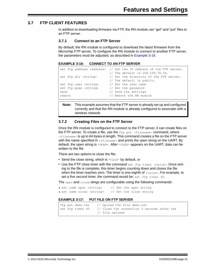
Features and Settings
3.7 FTP CLIENT FEATURES
In addition to downloading firmware via FTP, the RN module can “get” and “put” files to an FTP server.
3.7.1 Connect to an FTP Server
By default, the RN module is configured to download the latest firmware from the Microchip FTP server. To configure the RN module to connect to another FTP server, the parameters must be adjusted, as described in Example 3-16.
EXAMPLE 3-16: CONNECT TO AN FTP SERVER
3.7.2 Creating Files on the FTP Server
Once the RN module is configured to connect to the FTP server, it can create files on the FTP server. To create a file, use the ftp put <filename> command, where <filename> is up to 64 bytes in length. This command creates a file on the FTP server with the name specified in <filename> and prints the open string on the UART. By default, the open string is *OPEN*. After *OPEN* appears on the UART, data can be written to the file.
There are two options to close the file:
• Send the close string, which is *CLOS* by default, or
• Use the FTP close timer with the command set ftp timer <value>. Once writ-ing to the file is complete, this timer begins counting down and closes the file when the timer reaches zero. The timer is one-eighth of <value>. For example, to set a five second timer, the command would be: set ftp timer 40.
The open and close stings are configurable using the following commands:
• set comm open <string> // Set the open string• set comm close <string> // Set the close string
EXAMPLE 3-17: PUT FILE ON FTP SERVER
set ftp address <address> // Set the IP address of the FTP server.// The default is 208.109.78.34.
set ftp dir <string> // Set the directory of the FTP server. // The default is public.
set ftp user <string> // Set the user name set ftp pass <string> // Set the passwordsave // Save the settingsreboot // Reboot the RN module
Note: This example assumes that the FTP server is already set up and configured correctly and that the RN module is already configured to associate with a wireless network.
ftp put demo.txt // Upload the file demo.txtset ftp timer 40 // Close the connection 5 seconds after the
// file uploads
2014-2015 Microchip Technology Inc. DS50002230B-page 51

WiFly Command Reference Manual
3.7.3 Retrieving Files from the FTP Server
The RN module can retrieve files from the FTP server. The retrieved file is not stored in the RN module’s Flash memory. Instead, the RN module acts as a transporter and passes the file over the UART interface as the file is being transferred.
To retrieve a file from the FTP server, issue the ftp get <filename> command. The RN module prints the open string on the UART and the file begins transferring from the FTP server to the RN module. When the file transfer is complete, the RN module prints the close string indicating the file was transferred and the FTP connection was closed.
EXAMPLE 3-18: RETRIEVE FILE FROM FTP SERVER
ftp get demo.txt // Download the file demo.txt from the FTP server
DS50002230B-page 52 2014-2015 Microchip Technology Inc.

Features and Settings
3.8 PUTTING THE RN MODULE TO SLEEP AND WAKING IT
Table 3-18 describes the methods for putting the RN module to sleep.
Table 3-19 describes the methods for waking the RN module.
3.8.1 Determining When the RN Module is Ready to Accept Data
When the RN module wakes up from sleep, it takes time (in milliseconds) to initialize the internal hardware. During this time, any data that is sent to the RN module over the UART is not processed. Signals that indicate the RN module is ready to accept data can be monitored, as described in Table 3-20.
TABLE 3-18: METHODS FOR PUTTING THE RN MODULE TO SLEEP
Method Interface Description
Sleep Command UART Enter into Command mode using $$$ and issue the sleep command.
Sleep Timer Internal RTC The RN module sleeps based on the set sys sleep <value> command setting.
Drive GPIO8 high GPIO8 The RN module sleeps as soon as GPIO8 is held high (4 µs latency). To enable this feature, use the set sys trigger 0x20 command setting.
TABLE 3-19: METHODS FOR WAKING THE RN MODULE
Method Interface Description
Sensor Input(1.2V DC only)
Sensor pins Wake the RN module using sensor pins 0-3 (1.2V DC ONLY). Use the set sys trigger <value> command to enable the sensors.
RX pin(3.3V DC only)
RX pin via sensor 0 The RX pin on the RN134 and the RN174 evaluation boards is tied to sensor pin 0 via a resistor divider network. Use the set sys trigger 1 command to wake the RN module when it receives RX data.
Note: With this method, the RN module may drop the first UART data byte. A better method is to wake the RN module using the CTS pin.
CTS pin(3.3V DC only)
CTS pin via sensor 1 The CTS pin on the RN134 and the RN174 evaluation boards is tied to sensor pin 1 via a resistor divider network. Use the set sys trigger 2 command to wake the RN module using the CTS pin.
Wake Timer Internal RTC The wake timer wakes the RN module based on the set sys wake <value> command setting.
Force Awake FORCE AWAKE pin An input pulse of at least 31 µs (3.3V) wakes the RN module.
TABLE 3-20: SIGNALS INDICATING THE RN MODULE CAN ACCEPT DATA
Method Interface Description
RTS Transition RTS pin When the RN module wakes up, the RTS pin goes high. Once the RN module is ready, the RTS pin is driven low. This pin can be monitored with a microcontroller.
Monitor GPIO4 Alternative GPIO functions
Set the alternative functions for GPIO4, GPIO5, and GPIO6 (see Section 3.13.2.6 “Alternative GPIO4/GPIO5/GPIO6 Functions”). When the RN module wakes up and connects to an access point, GPIO4 goes high, indi-cating the RN module is ready to receive data over the UART. A microcontroller can monitor GPIO4.
Sensor Power Sensor power pin
The RN module can be configured to output VBAT, or 3.3V or 1.2V on the sensor power pin when it wakes from sleep, indicating it is ready to accept data.
2014-2015 Microchip Technology Inc. DS50002230B-page 53
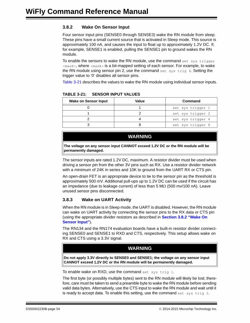
WiFly Command Reference Manual
3.8.2 Wake On Sensor Input
Four sensor input pins (SENSE0 through SENSE3) wake the RN module from sleep. These pins have a small current source that is activated in Sleep mode. This source is approximately 100 nA, and causes the input to float up to approximately 1.2V DC. If, for example, SENSE1 is enabled, pulling the SENSE1 pin to ground wakes the RN module.
To enable the sensors to wake the RN module, use the command set sys trigger <mask>, where <mask> is a bit-mapped setting of each sensor. For example, to wake the RN module using sensor pin 2, use the command set sys trig 4. Setting the trigger value to ‘0’ disables all sensor pins.
Table 3-21 describes the values to wake the RN module using individual sensor inputs.
The sensor inputs are rated 1.2V DC, maximum. A resistor divider must be used when driving a sensor pin from the other 3V pins such as RX. Use a resistor divider network with a minimum of 24K in series and 10K to ground from the UART RX or CTS pin.
An open-drain FET is an appropriate device to tie to the sensor pin as the threshold is approximately 500 mV. Additional pull-ups up to 1.2V DC can be used if the circuit has an impedance (due to leakage current) of less than 5 M (500 mv/100 nA). Leave unused sensor pins disconnected.
3.8.3 Wake on UART Activity
When the RN module is in Sleep mode, the UART is disabled. However, the RN module can wake on UART activity by connecting the sensor pins to the RX data or CTS pin (using the appropriate divider resistors as described in Section 3.8.2 “Wake On Sensor Input”).
The RN134 and the RN174 evaluation boards have a built-in resistor divider connect-ing SENSE0 and SENSE1 to RXD and CTS, respectively. This setup allows wake on RX and CTS using a 3.3V signal.
To enable wake on RXD, use the command set sys trig 1.
The first byte (or possibly multiple bytes) sent to the RN module will likely be lost; there-fore, care must be taken to send a preamble byte to wake the RN module before sending valid data bytes. Alternatively, use the CTS input to wake the RN module and wait until it is ready to accept data. To enable this setting, use the command set sys trig 2.
TABLE 3-21: SENSOR INPUT VALUES
Wake on Sensor Input Value Command
0 1 set sys trigger 1
1 2 set sys trigger 2
2 4 set sys trigger 4
3 8 set sys trigger 8
WARNING
The voltage on any sensor input CANNOT exceed 1.2V DC or the RN module will be permanently damaged.
WARNING
Do not apply 3.3V directly to SENSE0 and SENSE1; the voltage on any sensor input CANNOT exceed 1.2V DC or the RN module will be permanently damaged.
DS50002230B-page 54 2014-2015 Microchip Technology Inc.

Features and Settings
3.8.3.1 UART RECEIVER AND RTS/CTS HARDWARE FLOW CONTROL
The UART receive buffer is approximately 1,500 bytes. At lower baud rates (less than 115K), the system can send data over TCP/IP without flow control.
Depending on the frequency and quantity of the data being sent, the comm parameters optimize Wi-Fi performance by specifying when the system sends IP packets. To min-imize latency and TCP/IP overhead, use the flush size or match character to send data in a single IP packet. In most cases, set the flush timer to a large number to avoid fragmentation. For high throughput, increase the UART baud rate, set the flush size to 1,460, and set the flush timer to a large value so that full IP packets are sent.
Control packet forwarding can be controlled in the following ways:
• set comm match <value> sets the value of the packet terminator. Each time the RN module sees the match character it sends an IP packet. For example, set comm match 0xD forwards a packet when the RN module sees a 0xD hex character.
• set comm size <value> sets the flush size, where <value> is the number of bytes received before forwarding. The maximum is 1,460 bytes, which is the size of a single Ethernet frame.
• set comm time <value> sets the flush timer, which is used to flush any partial data sitting in the RX buffer if no additional data is received for <value> ms. For example, the set comm time 1000 command causes the RN module to wait for 1 second after no data was sent.
If the RN module will be sending more than a few hundred thousand bytes in a single transaction, hardware flow control should be enabled. The hardware must actively monitor the CTS pin. Flow control is not enabled by default and is set with the set uart flow 1 command.
It is possible to operate higher baud rates (i.e., greater than 115K) without flow control if the packets are uniform and an application protocol is used to ensure that the packet data is delivered on the remote side before the next packet is sent. However, given the uncertainty of packet delays in a TCP/IP network and the effects of interference and retries inherent in wireless networks, flow control is typically required whenever large, contiguous quantities of data are being written to the UART to ensure no data is lost.
2014-2015 Microchip Technology Inc. DS50002230B-page 55

WiFly Command Reference Manual
3.9 GPIO FUNCTIONS
This section provides information on GPIO functions.
3.9.1 Setting GPIO Direction, Alternate Functions, and Disabling LEDs
The GPIO pin direction and function are controlled using these two commands:
set sys maskset sys iofunc
3.9.1.1 CONTROL GPIO DIRECTION WITH SET SYS MASK
The GPIO pin direction can be controlled with the GPIO mask using the set sys mask <value> command, where <value> is entered as a hex number. The hex number rep-resents a bitmask that controls each pin, where 1 = output and 0 = input. For example:
set sys mask 0x0 // Sets all pins as inputsset sys mask 0xc0 // Set only GPIO6 and GPIO7
To set only one bit in the mask, it is necessary to read, mask, and set the value. Otherwise, any previous GPIO settings will be overwritten.
The default mask for the RN131 module is 0x20F0, which sets GPIO13, GPIO7, GPIO6, GPIO5, and GPIO4 as outputs.
The default mask for the RN171/RN1723 module is 0x21F0, which corresponds to the following settings:
• GPIO0-GPIO3 are used internally on the RN module
• GPIO4-GPIO6 are LEDs
• GPIO9 is reserved as the factory reset/Soft AP mode (read at power-up) and otherwise general purpose input detect pin
• GPIO10-GPIO11 are the UART RX and TX pins; TX does not need to be masked as an output
• GPIO12 is CTS (input), if used
• GPIO13 is RTS (output), if used
The RN134 evaluation board’s LEDs are connected to GPIO4-GPIO6. To disable the LEDs, enable the alternative functions of the LEDs (use the set sys iofunc 0x7 command).
The blue LED on the RN174 evaluation board is connected to GPIO7, which is output by default. The board does not drive this LED because the default power-up state of GPIO7 is low.
The get sys command shows the setting of the GPIO mask, as shown in Example 3-19.
EXAMPLE 3-19: GPIO MASK SETTING
Note: To set the GPIO pins as inputs or outputs instantly, use the set sys mask 0xABCD 1 command, which does not require a reboot.
Note: It is possible to turn OFF the yellow, red, or green LEDs. However, the blue LED on the RN134 evaluation board serves as the power indicator and cannot be turned OFF.
<2.21> get sysSleepTmr=……IoFunc=0x0IoMask=0x21f0
DS50002230B-page 56 2014-2015 Microchip Technology Inc.

Features and Settings
Figure 3-14 shows the bits corresponding to the GPIO pins and Table 3-22 shows the GPIO pin usage, their default state, and functionality.
FIGURE 3-14: GPIO PIN BITMASK
14 13 12 11 10 9 8 7 6 5 4 3 2 1 0GPIO0
GPIO1
GPIO2
GPIO3
GPIO4
GPIO5
GPIO6
GPIO7
GPIO14
GPIO13 UART RTS
GPIO12 UART CTS
GPIO11 UART RX
GPIO10 UART TX
GPIO9
GPIO8
TABLE 3-22: GPIO PIN USAGE, DEFAULT STATE, AND FUNCTIONALITY
Bit Signal NameRN131 Default
StateRN171/RN1723 Default State
Default Function
0 GPIO0 N/A N/A Not used by RN modules, but can be used as a sensor input.
1 GPIO1 N/A Input Not used by RN modules, but can be used as a sensor input.
2 GPIO2 N/A Input Not used by RN modules, but can be used as a sensor input.
3 GPIO3 N/A Input Not used by RN modules, but can be used as a sensor input.
4 GPIO4 Output Output Green LED
5 GPIO5 Output Output Yellow LED
6 GPIO6 Output Output Red LED
7 GPIO7 Output Output Blue LED(1)
8 GPIO8 Input Output This pin can be used to place the RN module into sleep mode.
9 GPIO9 Input Input Soft AP/Multi-purpose GPIO(2)
10 GPIO10 Output Output UART TX
11 GPIO11 Input Input UART RX
12 GPIO12 Input Input Throttles the transmitter if hardware flow control is enabled. Driving this pin low enables transmitter; driving this pin high disables it.
13 GPIO13 Output Output This pin goes high on power-up and goes low when the system is ready. If hardware flow control is enabled, this pin toggles to high to indicate the RX buffer is full.
14 GPIO14 N/A Input Not used by RN modules, but can be used as a sensor input.
Note 1: On the RN174 evaluation board, the blue LED is connected to GPIO7. The blue LED is not connected to GPIO7 on the RN134 evaluation board. It is not possible to power off the blue LED on the RN134 evaluation board because it is connected directly to power.
2: The GPIO9 pin can be used for factory Reset, Soft AP mode, or Web Config mode.
2014-2015 Microchip Technology Inc. DS50002230B-page 57

WiFly Command Reference Manual
3.9.1.2 SETTING THE ALTERNATE GPIO FUNCTIONS
The default functionality of GPIO4, GPIO5, and GPIO6 is to control the LEDs. The default can be overridden to allow user programmable I/O or alternate I/O functionality by using the set sys iofunc <mask> command, where <mask> is entered as a hex number. The hex value represents a bitmask that controls each bit in the <mask> and represents a particular GPIO pin. If a bit is ‘0’, the corresponding GPIO pin is driven/read by the firmware per the default function. The I/O function <mask> is encoded, as shown in Table 3-23.
If the LEDs are disabled using bits 0, 1, and 2, the show i command can be used to read these GPIO pins. For example, the show i command might return Port=30.
To use the alternate LEDs functions, use the following commands:
set sys iofunc 0x70 // Enable alternate function for GPIO4-GPIO6save // Store configurationreboot // Reboot the RN module
Example 3-20 shows how to control the LEDs on the evaluation boards.
EXAMPLE 3-20: TOGGLE RED AND GREEN LEDS
TABLE 3-23: GPIO PIN ALTERNATE FUNCTION BITMASK
Bit(1) Signal Name
Direction Function
0 GPIO4 Output Disable the LED function so the I/O can be used as a GPIO pin.
1 GPIO5 Output Disable the LED function so the I/O can be used as a GPIO pin.
2 GPIO6 Output Disable the LED function so the I/O can be used as a GPIO pin.
3 Unused — —
4 GPIO4 Output This pin goes high after the RN module has associated/authenticated and has an IP address.
5 GPIO5 Input Set this pin high to trigger a TCP connection and low to disconnect.
6 GPIO6 Output This pin goes high when the RN module is connected over TCP and low when disconnected.
Note 1: Bits 0-3 are mutually exclusive with bits 4-6 (i.e., 0x77 is an illegal value).
Green LED:set sys iofunc 0x01 // Mask GPIO4 from WiFly functionalityset sys output 0x10 // Toggle the state of GPIO4
Red LED:set sys iofunc 0x04 // Mask GPIO6 from WiFly functionalityset sys output 0x40 // Toggle the state of GPIO6
Green and Red LEDs:set sys iofunc 0x05 // Mask GPIO4 and GPIO6 from WiFly
// functionalityset sys output 0x50 // Toggle the state of GPIO 4 and GPIO6
DS50002230B-page 58 2014-2015 Microchip Technology Inc.

Features and Settings
3.10 SETTING DEBUG PRINT LEVELS
The print functions can be enabled to assist with debugging the operation and status of the RN module. The set sys printlvl <value> command controls these additional print functions, where <value> is a bit-mapped register that controls which printout messages are sent to the UART. See “set sys printlvl <value>” for more information.
3.10.1 Scan Output Format
The scan output format shown in the following example can be enabled using the set sys printlvl 0x4000 command.
Where:
Table 3-24 shows the security modes.
Table 3-25 describes the capabilities bit mask values.
Index Channel RSSISecurity
ModeCapabilities
WPA Configuration
WPS Mode
MAC Address
SSID
Field Value
Index 2 character, decimal
Channel 2 character, decimal
RSSI 2 character, decimal (negative number)
Security mode 2 bytes (see Table 3-24)
Capabilities Bit-mapped 4 hex bytes (see Table 3-25)
WPA Configuration Bit-mapped 2 hex bytes (see Table 3-26)
WPS Mode Bit-mapped 2 hex bytes (see Table 3-24)
MAC address Address
SSID Up to 32 characters
Note: The string END is added at the end of the scan data.
TABLE 3-24: SECURITY MODES
Number Description
0 OPEN
1 WEP (64 or 128)
2 WPA1
3 MIXED
4 WPA2
5 Enterprise WEP
6 Enterprise WPA1
7 Enterprise WPA mixed
8 Enterprise WPA2
9 Enterprise NO security
TABLE 3-25: CAPABILITIES BIT MASK VALUES
Bit Mask Value Description
0004 Short slot time
0100 ESS (Infrastructure mode)
1000 Privacy (secure with WEP or WPA)
2000 Short preamble
2014-2015 Microchip Technology Inc. DS50002230B-page 59

WiFly Command Reference Manual
Table 3-26 describes the WPA bit mask values.
Table 3-27 describes the WPS bit mask values.
3.10.2 UART Heartbeat Messages
The RN module can output UART heartbeat messages. The bit-mapped message is output periodically while the RN module is in Data mode and not connected to a remote Host. Messages are not output while in Command mode. The heartbeat message encodes the RN module’s state for the embedded microprocessor. Based on the heart-beat message, the microprocessor can choose to change the configuration by going into Command mode.
To enable the UART heartbeat messages, use the set sys printlvl 0x10 command. The output of this mode is: *8b30*8b30*8b30….
Table 3-28 shows the output bit format.
TABLE 3-26: WPA BIT MASK VALUES
Bit Mask Value Description
04 WPA_UNICAST_TKIP
08 WPA_UNICAST_AES_CCMP
10 WPA_BROADCAST_TKIP
20 WPA_BROADCAST_AES_CCMP
TABLE 3-27: WPS BIT MASK VALUES
Bit Mask Value Description
02 WPS_PushButton_ACTIVE
40 WPS_SUPPORTED
80 WPS_PushButton_SUPPORTED
Note: For Soft AP mode, the UART heartbeat message reflects the number of client devices associated with the RN module. In this case, the number 8 in the output is incremented according to the number of devices currently associated to the Soft AP network.For example:*81xx indicates no associated client devices, *91xx indicates one associated client device, and*a1xx indicates two associated client devices, etc.
TABLE 3-28: OUTPUT BIT FORMAT
Bit 15...14 13...12 11...8 7...6 5 4 3...0
Function Fixed Reserved Channel Reserved Authentication Association TCP status
Value
2 = Soft AP mode
Unused 0-13 Unused 1 = OK 1 = OK 0 = Idle1 = Connected3 = No IP4 = Connecting5 = Challenge for password
DS50002230B-page 60 2014-2015 Microchip Technology Inc.

Features and Settings
3.11 USING THE REAL-TIME CLOCK FUNCTION
The RN module’s real-time clock keeps track of the number of seconds since the RN module was powered on and the actual time when the RN module synchronized with the SNTP time server. By default, the RN module keeps track of up-time but does not synchronize with the time server because this synchronization requires the RN module to be associated with a network that can access the SNTP server. The real-time clock reads the time in seconds since 1970, which corresponds to the UNIX time.
The RTC value in seconds can be set using the set time rtc <value> command.
The default SNTP server is:
ADDR=129.6.15.28:123ZONE=7 (GMT -7)
Use the show time command to see the current time and up-time, as follows:
<2.23> show tTime=08:43:10UpTime=10 s
To set the time, use the time command:
<2. 23> show tTime NOT SETUpTime=8 s<2. 23> time<2. 23> show tTime=08:51:31UpTime=15 s
The RN module can also be configured to get the time whenever it powers up using the set time enable 1 command. If time enable is set to a value greater than ‘1’, the RN module pulls the time continuously every <value> minutes.
To configure the RN module to get time upon power-up, see the following example:
<2. 23> set time enable 1AOK<2. 23> get timeENA=1ADDR=129.6.15.28:123ZONE=7
To view a complete listing of the time variable, use the following command:
<2. 23> show t tTime=09:02:10UpTime=653 sRTC=1293567548Restarts=1Wake=6RAW=2345ab
Note: The RN module must be associated with a network for the RN module to contact the SNTP server.
Note: The RAW value is the 64-bit hex RAW value of the RTC, which counts at 32,768 Hz.
2014-2015 Microchip Technology Inc. DS50002230B-page 61

WiFly Command Reference Manual
3.12 TIME STAMPING PACKETS
The time stamping feature can be used to append 8 bytes to a TCP or UDP packet automatically. The set ip flags 0x87 command enables the time stamp and keeps other default settings). The time stamp bits from MSB to LSB are as follows:
The eight bytes represents the 64-bit raw value of the real-time clock register. The data is appended before calculating the TCP checksum so that the data passes through the TCP stack correctly. This register counts at 32,768 Hz. If the timeserver function is enabled, the RTC should accurately reflect the real time. This register also counts when the RN module is in Sleep mode.
User’s TCP or UDP packet data
63...56 55...48 47...40 39...32 31...24 23...16 15...8 7...0
DS50002230B-page 62 2014-2015 Microchip Technology Inc.

Features and Settings
3.13 SOFT ACCESS POINT (SOFT AP) MODE
RN modules support several methods for accessing Wi-Fi networks. In addition to Infrastructure mode, RN modules support Soft Access Point (Soft AP) mode.
In Soft AP mode:
• The RN module creates a Soft AP network to which Android devices (smartphones and tablets) can join
• The RN module runs a DHCP server and issues IP addresses to seven clients
• The RN module supports security
• The RN module supports routing between clients
The following sections describe how to use Soft AP mode with an RN module, including configuring the RN module to act as an access point, enabling Soft AP mode in hardware and software, and sending data to the RN module from a remote Host.
3.13.1 Enabling Soft AP mode
There are two methods for enabling Soft AP mode: hardware and software. These methods are described in the following sections.
3.13.1.1 ENABLE SOFT AP MODE IN HARDWARE
To enable Soft AP mode in hardware, hold the GPIO9 pin high at 3.3V, and then reset (i.e., power cycle) the RN module. The RN module will then boot-up in Soft AP mode with the DHCP server enabled.
Table 3-29 shows the default Soft AP mode settings.
When the RN module boots up in Soft AP mode, other Wi-Fi enabled devices, such as PCs, iPhones, iPads, and Android tablets, should be able to see the RN module when they scan for access points.
Note: Depending on the firmware version, Soft AP mode is available for use by RN modules, as follows:
• RN131 and RN171 modules with firmware version 2.45 and later
• RN1723 modules with firmware version 1.0 or later
TABLE 3-29: DEFAULT SOFT AP MODE SETTINGS
Setting Soft AP Mode Default
SSID WiFly-XXX-yy, where ‘XXX’ is:• GSX (RN131 module)• EZX (RN171 module)• FZX (RN1723 module)and ‘yy’ is the LSB byte of the RN module’s MAC address
Channel 1
DHCP server Enabled
IP address 192.168.1.1
Netmask 255.255.255.0
Gateway 192.168.1.1
Note: Microchip recommends setting the RN module as the gateway when creating a point-to-point network between devices (Wi-Fi network only).
2014-2015 Microchip Technology Inc. DS50002230B-page 63

WiFly Command Reference Manual
3.13.1.2 ENABLE SOFT AP MODE IN SOFTWARE
Soft AP mode can be enabled in software using the set wlan join 7 command. Net-work settings such as the SSID, channel, and IP address can be customized in software to create a custom Soft AP mode. For example, the following commands create a custom Soft AP mode in software:
set wlan join 7 // Enable Soft AP modeset wlan channel <value> // Specify the channel to create networkset apmode ssid <string> // Set up network broadcast SSID (BSSID)set apmode passphrase <string> // Set the Soft AP mode passphraseset ip dhcp 4 // Enable DHCP serverset ip address <address> // Specify the IP addressset ip net <address> // Specify the subnet maskset ip gateway <address> // Specify the gatewaysave // Store settings reboot // Reboot the RN module in Soft AP mode
After rebooting, the RN module is in Soft AP mode with the custom settings (SSID, channel, IP address, netmask, and gateway).
A quick method of creating a Soft AP network is to use the apmode <bssid> <channel> command, where <bssid> is the broadcast SSID and <channel> is the channel on which the Soft AP network is created. The <bssid> and <channel> parameters are optional. If no parameters are specified, the RN module:
• Uses the string stored with the set opt device_id <string> command and appends -xy, where ‘xy’ is the last byte of the RN module’s MAC address as the SSID
• Creates the Soft AP network on channel 1
Example
apmode MyNetwork 11 // Creates a Soft AP network on channel 11// with the SSID MyNetwork
3.13.2 Using Soft AP Mode
This section describes how to use Soft AP mode, including connecting to the RN module, checking for the last device connected over TCP, viewing associated devices, enabling the link monitor, and routing data between clients.
3.13.2.1 CONNECT TO THE RN MODULE
Once the RN module boots up in Soft AP mode, any client device can associate with the network the RN module is broadcasting. Once associated, the RN module’s DHCP server assigns an IP address to the client device.
The default lease time is 1 day (i.e., 86,400 seconds). The lease time can be configured using the set dhcp lease <value> command, where <value> is the time in seconds. To view a list of devices associated with the RN module, use the show lease command. The command output is in the following format with commas delimiting the fields:
Note: This command does not survive power cycling. After a power cycle, the RN module behaves according to the wireless join policy determined by the set wlan join <value> command.
IP address assigned Client MACaddress
Remaining lease time(in seconds)
Host name
DS50002230B-page 64 2014-2015 Microchip Technology Inc.

Features and Settings
Example 3-21 shows output from the show lease command.
EXAMPLE 3-21: SHOW LEASE COMMAND OUTPUT
Once a client is associated to the network, it can open a TCP connection to the RN module. After successfully opening a TCP connection, the client receives a *HELLO* message. The RN module prints *OPEN* on the UART, indicating an open TCP connection.
3.13.2.2 CHECK FOR THE LAST CONNECTED DEVICE OVER TCP
In some cases, it is beneficial to know the IP address of the last device that connected to the RN module over TCP or the last device to which the RN module connected over TCP. To find this address, use the show z command. Please note that this command does not survive a power cycle or reboot.
Upon power-up, if no device is connected over TCP, the show z command returns 0.0.0.0.
3.13.2.3 VIEW ASSOCIATED DEVICES
To see a list of devices associated with the RN module, use the show associated com-mand. The command output is in the following format with commas delimiting the fields:
Example 3-22 shows output from the show associated command.
EXAMPLE 3-22: SHOW ASSOCIATE COMMAND OUTPUT
The “Seconds since last packet received” output can be used to check for stale connections.
<2.42> show lease1.2.3.10,f0:cb:a1:2b:63:59,153,*1.2.3.11,00:00:00:00:00:00,0,1.2.3.12,00:00:00:00:00:00,0,1.2.3.13,00:00:00:00:00:00,0,1.2.3.14,00:00:00:00:00:00,0,1.2.3.15,00:00:00:00:00:00,0,1.2.3.16,00:00:00:00:00:00,0,<2.42>
Note: In Soft AP mode, the RN module can assign a DHCP lease to seven clients. However, not all clients report the Host name. In this case, the RN module reports the Host name as an asterisk (*).
Connection number
Host MAC address
Received byte count
Transmitted byte count
Seconds since last packet received
<2.42> show associated1,f0:cb:a1:2b:63:59,36868,0,72,00:24:8c:31:e5:27,76168,0,23,98:4b:4a:6b:e0:0f,1992,0,0<2.42>
2014-2015 Microchip Technology Inc. DS50002230B-page 65

WiFly Command Reference Manual
3.13.2.4 ENABLE THE LINK MONITOR
Soft AP mode supports a link monitor feature to detect whether or not individual client devices are active and in range of the RN module. The link monitor is a timer (in seconds) that checks to see if any packets are received from an associated device. If the timer expires, the access point module deauthenticates the client(s). This feature is useful for aging out clients that do not send any traffic over Wi-Fi.
The link monitor is enabled using the set wlan fmon <value> command, where <value> is a decimal number representing the number of seconds of client inactivity (i.e., no data received from the client device). This command sets the Soft AP mode link monitor time-out threshold for each associated client device. When this timer expires, the RN module deauthenticates that particular client.
Setting this timer to a lower value, such as 10 seconds, may result in frequent deauthentications for client devices if they do not send data before the timer expires.
To disable the link monitor timer, set <value> to zero (0). The default is 3600.
Example
set wlan fmon 1000 // Set the fmon timer to 1,000 seconds
3.13.2.5 ROUTE DATA BETWEEN CLIENTS
Soft AP mode supports routing between clients. Clients can ping each other via Soft AP mode and can also send data to each other over TCP and UDP.
3.13.2.6 ALTERNATIVE GPIO4/GPIO5/GPIO6 FUNCTIONS
GPIO4, GPIO5, and GPIO6 have alternative functions in Soft AP mode, as described in 3.13.2 “Using Soft AP Mode”. The alternative functions are enabled using the following command:
set sys iofunc 0x70 // Enables alternative functions
The link monitor feature must be enabled to turn on the alternative functions in Soft AP mode only. Table 3-30 shows the GPIO alternative functions.
Note: Routing data between clients is not supported when WPA2-PSK encryption is enabled.
TABLE 3-30: ALTERNATIVE GPIO FUNCTIONS
GPIO Description
GPIO4 High when the first client associates; low when all clients leave the network.
GPIO5 The RN module can drive GPIO5 high to open a TCP connection to a stored host. When the RN module drives GPIO5 low, it closes the TCP connection.
GPIO6 The RN module drives GPIO6 high when a TCP connection is open and low when a TCP connection is closed.
DS50002230B-page 66 2014-2015 Microchip Technology Inc.

Features and Settings
3.14 UPGRADING FIRMWARE
3.14.1 Upgrading Firmware Via FTP
The RN module has a file system for storing firmware and configuration files. Use the ls command to view files. The file size is displayed in sectors and the active boot image is identified in the final message. For example:
FL# SIZ FLAGS 11 18 3 WiFly_GSX-2.21 29 1 10 config190 Free, Boot=11, Backup=0
It is possible to store multiple firmware images and configuration files in the file system of the RN module.
The RN module contains a built-in FTP client for downloading files and updating the firmware. The client uses passive mode FTP, which allows operation through firewalls and the Internet. To connect to Microchip to obtain the latest released firmware, use the settings shown in Table 3-31.
3.14.1.1 UPGRADING WITH MULTIPLE IMAGE FORMAT (MIF) FILES
The MIF (.mif) files contain the firmware image (.img) and associated applications and files to support all of the features of the installed firmware. RN modules that support the MIF file format can unpack the .mif file and install the applications and files into the RN module’s Flash memory.
Download the .mif file using one of the following commands:
• ftp update wifly3-400.mif (RN131 module)
• ftp update wifly7-400.mif (RN171 module)
• ftp update wifly7-100.mif (RN1723 module)
Note: The RN module’s Flash file system only is used to store firmware and configuration files. The file system cannot be used to store data files.
TABLE 3-31: FTP SETTINGS
Setting Description
FTP server rn.microchip.com (set FTP server using the set dns backup <string> command)
FTP username roving
FTP password Pass123
FTP filename Refer to the following sections for the filename used in different versions of firmware.
FTP directory ./public (this parameter cannot be modified)
Note: Before using FTP to upgrade the firmware, the RN module must first be associated with an access point that is connected to the Internet.
Note: Upgrading using the MIF file description, is only available for the following RN modules:
• RN131 and RN171 modules with firmware version 4.0 and later
• RN1723 modules with firmware 1.0 or later
2014-2015 Microchip Technology Inc. DS50002230B-page 67

WiFly Command Reference Manual
After downloading the .mif file, the RN module unpacks it and automatically reboots into the new boot image with all of the associated files installed into the RN module’s Flash memory. Table 3-32 describes these files.
The firmware image, applications, and associated files in the Flash memory can be verified using the ls command, as shown in Example 3-23.
EXAMPLE 3-23: ls COMMAND EXAMPLE OUTPUT
TABLE 3-32: FIRMWARE AND ASSOCIATED APPLICATIONS
File Name Description Comments
wifly_EZX-2.45wifly-EZX-307wifly-EZX-400wifly-FZX-100
Firmware image files (.img)
Filenames beginning in wifly are typically firmware images.
wps_app-EZX-131eap_app-EZX-101web_app-EZX-105web_app-FZX-112
Application files These application files are used for specific module features.
web_config.htmllink.html
HTML files These files are used for the configuration Web Server feature.
logo.png Logo file Logo displayed on web pages. Used for the configuration Web Server feature.
config Configuration file The config file stores the RN module’s boot-up parameters.
<3.07> lsFL# SIZ FLAGS
2 83576 3 WiFly_EZX-2.45 23 -1 10 config 25 85512 3 wifly-EZX-307 26 46624 3 wps_app-EZX-131 27 66248 3 eap_app-EZX-101 28 74280 3 web_app-EZX-105 29 37014 0 web_config.html 30 512 0 link.html 31 1609 0 logo.png149 Free, Boot=25, Backup=2
<3.07>
DS50002230B-page 68 2014-2015 Microchip Technology Inc.

Features and Settings
3.14.1.2 UPGRADING FIRMWARE TO VERSION 4.0
To update the firmware from a version prior to 4.0, follow this process:
1. Update the firmware .img file to version 4.xx using one of the following commands:
• ftp update wifly3-400.img (RN131 module)
• ftp update wifly7-400.img (RN171 module)
2. Remove the old configuration using the following command:
del config
3. Reboot the RN module to boot into the new image.
4. Download the .mif file using one of the following commands:
• ftp update wifly3-400.mif (RN131 module)
• ftp update wifly7-400.mif (RN171 module)
After the RN module downloads the .mif file, the RN module automatically reboots into the boot image with all of the associated files installed into the RN module’s Flash memory. Refer back to Table 3-32 for a description of these files. The firmware image, applications, and associated files in Flash memory can be verified using the ls com-mand (see Example 3-23).
3.14.1.3 UPGRADING FIRMWARE PRIOR TO VERSION 4.0
To update the firmware to a version prior to 4.0 (e.g., from version 2.45 to 3.07), issue the command ftp update <filename>, where <filename> is an optional file name (use the optional name to bypass the default firmware file name).
The RN module retrieves the file and switches the boot image to the new file, resulting in the following messages:
<2.20> ftp update<2.20> FTP connecting to 208.109.78.34FTP file=30......................................................................FTP OK.
Note: Upgrading firmware to version 4.0 is only applicable to the RN131 and RN171 modules.
NOTICE
It is mandatory that the RN module be reset to the factory default settings at this point using the factory RESET and reboot commands.
Note: Upgrading firmware to a version prior to 4.0 is only applicable to the RN131 and RN171 modules.
CAUTION
After the RN module reboots with the new firmware, it is recommended to reset the RN module to the factory default parameters using the factory RESET command. Failure to do so may result in some variables being initialized with random values.
2014-2015 Microchip Technology Inc. DS50002230B-page 69

WiFly Command Reference Manual
The previous firmware becomes the back-up image. The following example shows the file system after a successful update:
FL# SIZ FLAGS 11 18 3 WiFly_GSX-2.20 29 1 10 config 30 18 3 WiFly_GSX-2.21208 Free, Boot=30, Backup=11
After downloading, the firmware checks the image and compares it to the stored values in the file before committing the image to Flash and updating the boot record. If the checksum fails, the RN module displays UPDATE FAILED=x and deletes the image.
For example, issue the following command to boot the previous image using the previous example:
<2.20> boot image 11Set Boot Image 11, =OK
3.14.1.4 OPTIONAL FTP UPDATE COMMAND PARAMETERS
The optional FTP update command parameter options are:
ftp <option>update <filename>
where <option> is:
u – download firmware and set as boot image <filename> is the name of the firmware (.img or .mif file)
c – clean the file system option before performing firmware update over FTP. This will delete all the files on the Flash file system (including user-defined configuration files) except the current boot image and the factory default boot image (sector 2).
Note: It is necessary to reboot or power cycle the RN module to use the new firmware. To boot with different firmware, use the command boot image <value>, which sets the current boot image as <value>.
Note: After changing the boot pointer to the new image, the RN module must be rebooted to boot up with the new image. Once the RN module boots up with the new image, perform a factory reset on the RN module to initialize all the parameters to the factory default settings. Then, the parameters can be reinitialized as required.
Note: The optional FTP update command parameters apply to:
• RN131 and RN171 modules with firmware version 4.40 and later
• RN1723 modules with firmware 1.0 or later
DS50002230B-page 70 2014-2015 Microchip Technology Inc.

Features and Settings
3.14.1.4.1 FTP Update Procedure Example
Step 1: Issue the FTP update command.
ftp cupdate wifly7-440.mif
After a successful firmware update, the RN module will automatically boot into the new image.
Step 2: Perform a factory reset and reboot the RN module.
factory RESETreboot
During the process, the UART console echoes the status of the FTP update:
<4.40> ftp cupdate wifly7-440.mif del 4 wifly-EZX-405 del 5 config del 6 reboot del 8 logo.png del 13 wps_app-EZX-131 del 14 eap_app-EZX-105 del 15 web_app-EZX-112 del 16 web_config.html del 17 link.htmlFTP connecting to 198.175.253.161
FTP file=4:..................................................................FTP file=5:..................................FTP file=6:.................................................FTP file=8:..........................................................FTP file=9:......................................FTP file=10:...FTP file=11:.......UPDATE OK*Reboot*.wifly-EZX Ver: 4.40 Build: r1018, Oct 31 2013 09:45:31 on RN171MAC Addr=00:06:66:71:0f:d4
*READY*
Note 1: If the RN module does not have Internet access or is unable to contact the FTP server, it will still perform the file system clean.
2: To prevent file system clean-up prior to the FTP update, do not specify the clean-up in the ftp update command.
3: It is recommended to initialize the RN module with factory default settings after a successful FTP update in order to avoid the *BAD-CONFIG* message due to a configuration file mismatch between old and new firmware versions.
WARNING
When updating an RN131 or RN171 module image from version 4.40 to an earlier version, it is required to use the ftp cu <filename> command to delete the existing configuration file prior to downloading the new image. Alternatively, the del config command can be used followed by the ftp u <filename> command.Failure to delete the configuration file using one of the these two methods may result in the RN module being unresponsive after downloading the new firmware image. Restoring the RN module to factory defaults using GPIO9 will recover from this state.
2014-2015 Microchip Technology Inc. DS50002230B-page 71

WiFly Command Reference Manual
3.14.2 Firmware Update over UART via XMODEM 1K Protocol
Firmware updates over UART using the XMODEM 1K protocol is supported by RN131 and RN171 modules with firmware 4.40 and later or RN1723 modules with firmware version 1.0 or later.
Prerequisites:
• Must have a local copy of a .img or .mif firmware file. The .img file always contain a single module firmware application. The .mif file may contain module firmware and other application(s) such as web_app, wps_app and/or custom files.
• Software application capable of sending files over serial port via the XMODEM-1K protocol (e.g., Tera Term for Windows or CoolTerm for Mac)
3.14.2.1 UPDATING FIRMWARE USING THE TERA TERM TERMINAL OVER XMODEM 1K PROTOCOL
1. Connect the RN module to the PC and open Tera Term.
2. To increase download speeds, set the baud rate to 230400 by sending the WiFly commands: set uart baud 230400 //set baud rate to 230400set uart flow 1 //enable UART flow controlsavereboot
3. Set the baud rate to 230400 and enable Hardware flow control).
4. Enter the following WiFly command to enable Xmodem mode: xmodem <option> <filename>
where <option> is:
u – download firmware and set as boot image <filename> is the name of the firmware (.img or .mif file)
c – clean the file system before performing firmware update over FTP or the XMODEM 1K protocol. This will delete all the files on the Flash file system (including user defined configuration files) except the current boot image and the factory default boot image (sector 2)
Example:
xmodem cu wifly7-400.mif
Once the command is entered, output similar to the following should appear.
<4.40> xmodem cu wifly7-400.mif del 4 wifly-EZX-405 del 5 config del 6 reboot del 8 logo.png del 13 wps_app-EZX-131 del 14 eap_app-EZX-105 del 15 web_app-EZX-112 del 16 web_config.html del 17 link.html
xmodem ready...<4.40>
Note: The RN In-System Programmer (RN-ISP) is not required to update the firmware.
Note: The RN module deletes all files from the Flash file system, except the current boot image and the factory default boot image.
DS50002230B-page 72 2014-2015 Microchip Technology Inc.

Features and Settings
5. Once XMODEM is ready on the UART, proceed to the XMODEM file transfer option in Tera Term by selecting the File > Transfer > XMODEM > Send option.
FIGURE 3-15:
6. Select the 1K option, enter the .img or .mif file path, and click Open.
FIGURE 3-16:
7. The new firmware and/or web files will download to the RN module. If everything was successful, a message similar to the following should appear: <4.40> XMOD OK.
8. At this point, the firmware should be downloaded to the RN module. Issue an ls command to ensure everything worked properly.
Note: There is a default 30 second timeout from when the xmodem command is issued. To disable this time-out, enter the command: set ftp timeout 0
2014-2015 Microchip Technology Inc. DS50002230B-page 73

WiFly Command Reference Manual
3.15 ANALOG SENSOR CAPABILITY
The RN module has eight analog sensor inputs that can be driven between 0V to 1.2V DC. The analog inputs can be sampled and the digital value read using the show q <value> command, where <value> is a decimal number representing the channel. See “show q <value>” for more information.
The channel is the analog sensor input from 0 to 7. The value for the analog sensor input is measured in microvolts and is returned as 8xxxxx, where the beginning 8 is a start marker.
Multiple channels can be sampled using a bit mask through the show q 0x1 <mask> command, where <mask> is a bit mask of the channels. See “show q 0x1<mask>” for more information.
EXAMPLE 3-24: READ CHANNELS 0, 1, AND 7
The results of the read are in the following format:
8<channel 0>, 8<channel 1>, 8<channel 7>\r\n
The analog input hardware specification is:
• Input voltage range: 0V-1.2V (the ADC saturates at 400 mV)
• Resolution: 14 bits = 12 µV
• Sampling frequency: 35 µs
• Accuracy: 5 percent uncalibrated
The accuracy of each analog sensor reading can be offset by up to 5 percent due to variations in devices. To improve accuracy, it is recommended to use a precision reference voltage on one of the analog inputs to calculate the offset. The offset is the same for all analog inputs. For example:
• Drive precision 200 mV reference on analog input 4
• Read analog input 4 and compute the offset
If 210 mV is read, this indicates that the offset is +10 mV. If input 5 is read, subtract 10 mV from the result.
3.15.1 Sampling Sensor Pins Automatically
The sensor pins can be sampled automatically and data forwarded in two modes:
• The UDP broadcast packet can contain the sample values.
• In HTTP mode, the sampled pin data can be forwarded to a remote server
To enable these modes, use the set q sensor <mask> command.
EXAMPLE 3-25: SAMPLE ALL SENSOR INPUTS
WARNING
Driving these inputs above 1.2V can permanently damage the RN module.
show q 0x183 // Read channels 0, 1, and 7
set q sensor 0xff // Sample all sensor inputs
DS50002230B-page 74 2014-2015 Microchip Technology Inc.

Features and Settings
3.15.2 Using the Built-In Sensor Power
The RN modules contain an on-board sensor power pin, which is controlled by the set q sensor <mask> command, where <mask> is a bit mask value that determines which sensor pins to sample when sending data using the UDP broadcast packet or the HTTP auto-sample function. See “set q sensor <mask>” for information.
Use the set q power <value> command to set the set the power value. See “set q power <value>” for information on using this command.
2014-2015 Microchip Technology Inc. DS50002230B-page 75

WiFly Command Reference Manual
NOTES:
DS50002230B-page 76 2014-2015 Microchip Technology Inc.

WiFly COMMANDREFERENCE MANUAL
Chapter 4. Command Reference
This chapter lists and describes the WiFly commands that can be used to configure an RN module.
Topics include:
• Command Syntax
• Command Organization
• Set Commands
• Get Commands
• Status Commands
• Action Commands
• File I/O Commands
4.1 COMMAND SYNTAX
To issue WiFly commands to an RN module, a keyword is sent followed by optional parameters. The following syntax rules apply:
• Commands are case sensitive
• Hex input data can be uppercase or lowercase
• String text data, such as the SSID, is case sensitive
• Spaces cannot be used in parameters. Instead, a dollar sign character, $, is used to indicate a space. For example, the parameter MY NETWORK should be written as MY$NETWORK
• Shorthand can be used for the parameters. For example, the following commands are equivalent:- set uart baudrate 115200- set uart b 115200- set u b 115200
• Numbers can be entered in either decimal or hexadecimal. The syntax to enter a number in hex is 0x<value>. For example, the hex value, FF, would be entered as 0xFF
Note: Shorthand cannot be used for command keywords. For example, abbreviating the command keyword ‘set’ to ‘s’ is invalid.
2014-2015 Microchip Technology Inc. DS50002230B-page 77

WiFly Command Reference Manual
4.2 COMMAND ORGANIZATION
There are five command categories, as listed in Table 4-1.
When the system boots, all configuration data is loaded into RAM variables from the configuration file. The Set commands only modify the RAM copy of the system variables. In general, the IP, WLAN, and UART settings require a save and reboot before they take effect because they operate upon power-up. For example, associating, setting the channel, and obtaining an IP address only once at power-up. Most of the other commands, such as the set comm series of commands and timers, take effect immediately, allowing parameters to be changed on-the-fly, minimizing power usage, and saving Flash rewrite cycles.
Once configuration is complete, the settings must be saved to store the configuration data; otherwise, they will not take effect upon reboot or reset. Multiple configurations can be stored using the save <filename> command, and can be loaded using the load <filename> command.
TABLE 4-1: COMMAND TYPES
Command Type Description
Set commands Set commands take effect immediately and are stored to memory when the save command is issued.
Get commands These commands retrieve and display the stored information.
Status commands These commands display the interface status, IP status, etc.
Action commands Use these commands to perform actions such as scanning, connecting, disconnecting, etc.
File I/O commands Use these commands to upgrade, load and save a configuration, delete files, etc.
Note: Any changes made must be saved using the save command or the RN module will load the previous settings upon reboot or power-up.
DS50002230B-page 78 2014-2015 Microchip Technology Inc.

Command Reference
4.3 SET COMMANDS
The Set commands begin with the set keyword and include the parameter categories listed in Table 4-2.
Table 4-3 lists and describes all WiFly Set commands, which are grouped by function. Detailed descriptions of each command, which are grouped by function follow the table.
TABLE 4-2: SET COMMAND PARAMETER CATEGORIES
Parameter Description
apmode Controls the Access Point (Soft AP) parameters.
broadcast Controls the broadcast hello/heartbeat UDP message.
comm Sets the communication and data transfer, timers, and matching characters.
dns Sets the DNS host and domain.
ftp Sets the FTP host address and login information.
ip Specifies the IP settings.
option Supports optional and infrequently used parameters.
sys Sets system settings such as sleep and wake timers.
time Sets the timer server settings.
uart Specifies the serial port settings such as baud rate and parity.
wlan Sets the wireless interface settings, such as SSID, channel, and security options.
TABLE 4-3: SET COMMANDS
Command Default Description
APMODE Commands
set apmode beacon <value> 102 Sets the Soft AP beacon interval in milliseconds.
set apmode link monitor <value> 3600 This command is used in Soft AP mode to detect if the individual client devices are active and in range of the RN module.
set apmode passphrase <string> NULL This command sets the Soft AP mode passphrase to be used for WPA2-AES encryption.
set apmode probe <value> 5 Sets the Soft AP mode probe time-out in seconds.
set apmode reboot <value> 0 Sets the reboot timer.
set apmode ssid <string> NULL This command sets the Soft AP network name (SSID) to be broadcast where <string> is the SSID.
BROADCAST Commands
set broadcast address <address> 255.255.255.255 Sets the address to which the UDP hello/heartbeat message is sent.
set broadcast backup <address> 0.0.0.0 Sets the secondary broadcast back-up address.
set broadcast interval <mask> 7 Sets the interval (in seconds) at which the hello/heartbeat UDP message is sent.
set broadcast port <value> 55555 Sets the port to which the UDP hello/heartbeat message is sent.
set broadcast remote <port> 0 Sets the secondary broadcast port.
2014-2015 Microchip Technology Inc. DS50002230B-page 79

WiFly Command Reference Manual
COMM Commands
set comm $ <char> $ Sets character used to enter command mode to <char>.
set comm close <string> *CLOS* Sets the ASCI string that is sent to the local UART when the TCP port is closed.
set comm idle <value> 0 Sets the idle timer value in seconds.
set comm match <value> | <hex> 0 Sets the match character in hex or decimal.
set comm open <string> *OPEN* Sets the ASCI string that is sent to the local UART when the TCP port is opened.
set comm remote <string> *HELLO* Sets the ASCI string that is sent to the remote TCP client when the TCP port is opened.
set comm size <value> 64 Sets the flush size in bytes.
set comm time <value> 5 Sets the flush timer.
DHCP Command
set dhcp lease <value> 86400 Sets the Soft AP mode DHCP lease time in seconds.
DNS Commands
set dns address <address> 0.0.0.0 Sets the IP address of the DNS sever.
set dns backup <string> rn.microchip.com Sets the name of the back-up host for TCP/IP connections to <string>.
set dns name <string> server1 Sets the name of the host for TCP/IP connections to <string>.
FTP Commands
set ftp addr <address> 0.0.0.0 Sets the FTP server’s IP address of the FTP server.
set ftp dir <string> public Sets the starting directory on the FTP server.
set ftp filename <filename> See description Sets the name of the file that is transferred when issuing the ftp u command, where <filename> is the name of the firmware image.
The firmware version 4.0 defaults are:• wifly3-<version>.img (RN131)• wifly7-<version>.img (RN171/RN1723)
The firmware prior to version 4.0 defaults are:• wifly-GSX-<version>.img (RN131)• wifly-EZX-<version>.img (RN171)
set ftp pass <string> Pass123 Sets the password for accessing the FTP server.
set ftp mode <mask> 0x0 Sets the FTP mode, where <mask> indicates active or passive mode. Default is passive.
set ftp remote <value> 21 Sets the FTP server’s remote port number.
set ftp time <value> 200 Sets the FTP timeout value, where <value> is a decimal number that is five times the number of seconds required.
set ftp user <string> roving Sets the user name for accessing the FTP server.
TABLE 4-3: SET COMMANDS (CONTINUED)
Command Default Description
DS50002230B-page 80 2014-2015 Microchip Technology Inc.

Command Reference
IP Commands
set ip address <address> 0.0.0.0 Sets the IP address of the RN module.
set ip backup <address> 0.0.0.0 Sets a secondary host IP address.
set ip dhcp <value> 1 Enables/disables DHCP mode.
set ip flags <mask> 0x7 Sets the TCP/IP functions.
set ip gateway <address> 0.0.0.0 Sets the gateway IP address.
set ip host <address> 0.0.0.0 Sets the remote host’s IP address.
set ip localport <value> 2000 Sets the local port number.
set ip netmask <address> 255.255.255.0 Sets the network mask.
set ip protocol <flag> 2 Sets the IP protocol.
set ip remote <value> 2000 Sets the remote host port number.
set ip tcp-mode <mask> 0x0 Controls the TCP connect timers, DNS preferences, and remote configuration options.
OPT Commands
set opt average <value> 5 Sets the number of RSSI samples used to calculate the running RSSI average.
set opt deviceid <string> WiFly-XXX Sets the configurable device ID, where ‘XXX’ is GSX for the RN131 and EZX for the RN171/RN1723.
set opt format <flag> 0x00 Sets the HTTP Client/Web Server information.
set opt jointmr <value> 1000 Sets the join timer, which is the length of time in milliseconds that the join function waits for the access point to complete the association process.
set opt replace <char> $ (0x24) Sets the replacement character to use for indicating spaces in the SSID and passphrases, where <char> is a single character.
set opt password <string> “” (no password required)
Sets the TCP connection password.
set opt signal <value> 0 Configures the threshold level for the RSSI value in infrastructure mode.
Q Commands
set q power <value> 0 Automatically turns on the sensor power.
set q sensor <mask> 0 Specifies which sensor pins to sample when sending data using the UDP broadcast packet or the HTTP auto sample function.
TABLE 4-3: SET COMMANDS (CONTINUED)
Command Default Description
2014-2015 Microchip Technology Inc. DS50002230B-page 81

WiFly Command Reference Manual
SYS Commands
set sys autoconn <value> 0 Sets the auto-connect timer in TCP mode.
set sys autosleep <value> 0 Sets the auto-sleep timer in UDP mode.
set sys iofunc <mask> 0x0 Sets the I/O port alternate functions.
set sys launch_string <string> web_app Sets the application to launch when the GPIO9 pin is high after power-up.
set sys mask <mask> 0x20F0 (RN131) 0x21F0 (RN171/RN1723)
Sets the I/O port direction.
set sys printlvl <value> 0x1 Controls the debug print messages printed by the RN module on the UART.
set sys output <mask> <mask> None sets the output GPIO pins high or low. The optional <mask> sets a subset of the pins.
set sys sleep <value> 0 Sets the sleep timer.
set sys trigger <flag> or <mask>
0x1 With this parameter setting, the RN module wakes from sleep state using the sensor input 0, 1, 2, and 3.
set sys value <mask> 0x0 Sets the default value of the GPIO pins’ outputs upon power-up.
set sys wake <value> 0 Sets the automatic wake timer in seconds.
set sys z <value> 0 Sets the minimum CPU doze time in milliseconds (only available on RN1723-based modules).
Time Commands
set time address <address> 64.90.182.55 Sets the time server address.
set time enable <value> 0 Tells the RN module how often to fetch the time from the specified SNTP time server in minutes.
set time port <value> 123 Sets the time server port number.
set time raw <value> None Enables setting the RTC raw value in seconds from the console.
UART Commands
set uart baud <value> 9600 Sets the UART baud rate, where <value> is 2400, 4800, 9600, 19200, 38400, 57600, 115200, or 230400.
set uart cmdgpio <value> 0 Allows the GPIO1 pin to be used to enable (1) or disabled (0) Command mode (only available on RN1723-based modules).
set uart flow <value> 0 Sets the flow control mode and parity.
set uart instant <value> Not applicable Immediately changes the baud rate, where <value> is 2400, 4800, 9600, 19200, 38400, 57600, 115200, or 230400.
set uart mode <mask> 0 Sets the UART mode register.
set uart raw <value> Not applicable Sets a raw UART value.
set uart tx <value> Not applicable Disables or enables the UART’s TX pin (GPIO10), where <value> is 1 or 0.
TABLE 4-3: SET COMMANDS (CONTINUED)
Command Default Description
DS50002230B-page 82 2014-2015 Microchip Technology Inc.

Command Reference
WLAN Commands
set wlan auth <value> 0 Sets the authentication mode.
set wlan channel <value> <flag> 0 Sets the WLAN channel, where <value> is a decimal number from 1 to 13 representing a fixed channel and <flag> is the optional character ‘i’ (meaning immediate).
set wlan ext_antenna <value> 0 Determines which antenna is active, where <value> is 0 (use the chip antenna) or 1 (use the U.FL connector).
set wlan fmon <value> 3600 Sets the Soft AP mode link monitor timeout threshold for the associated client device.
set wlan id <string> Not applicable Reserved for future use.
set wlan hide <value> 0 Hides the WEP key and WPA passphrase, where <value> is 0 or 1.
set wlan join <value> 1|0 Sets the policy for automatically associating with network access points.
set wlan key <value> Not applicable Sets the 128-bit WEP key, where <value> is exactly 26 ASCII chars (13 bytes) in hex without the preceding 0x.
set wlan linkmon <value> 0 (disabled) Sets the link monitor timeout threshold, where <value> is a decimal number representing the number of failed scans before the RN module declares “Soft AP is Lost” and deauthenticates.
set wlan mask <mask> 0x1FFF (all channels)
Sets the WLAN channel mask, which is used for scanning channels with auto-join policy 1 or 2.
set wlan phrase <string> rubygirl Sets the passphrase for WPA and WPA2 security modes.
set wlan number <value> 0 Sets the WEP key number.
set wlan rate <value> 12 Sets the wireless data rate.
set wlan ssid <string> roving1 Sets the SSID with which the RN module associates.
set wlan tx <value> 0 Sets the Wi-Fi transmit power, where <value> is a decimal number from 1 to 12 that corresponds to 1 to 12 dBm.
set wlan user <string> Not applicable Reserved for future use.
TABLE 4-3: SET COMMANDS (CONTINUED)
Command Default Description
2014-2015 Microchip Technology Inc. DS50002230B-page 83
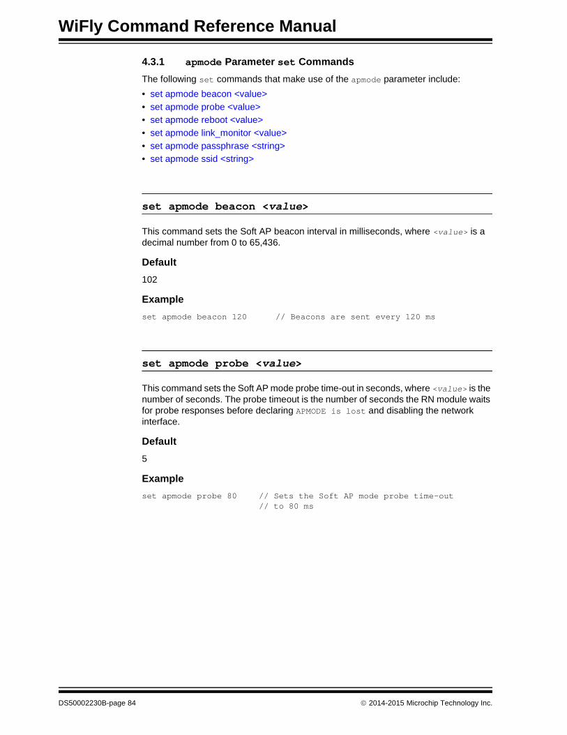
WiFly Command Reference Manual
4.3.1 apmode Parameter set Commands
The following set commands that make use of the apmode parameter include:
• set apmode beacon <value>
• set apmode probe <value>
• set apmode reboot <value>
• set apmode link_monitor <value>
• set apmode passphrase <string>
• set apmode ssid <string>
set apmode beacon <value>
This command sets the Soft AP beacon interval in milliseconds, where <value> is a decimal number from 0 to 65,436.
Default
102
Example
set apmode beacon 120 // Beacons are sent every 120 ms
set apmode probe <value>
This command sets the Soft AP mode probe time-out in seconds, where <value> is the number of seconds. The probe timeout is the number of seconds the RN module waits for probe responses before declaring APMODE is lost and disabling the network interface.
Default
5
Example
set apmode probe 80 // Sets the Soft AP mode probe time-out // to 80 ms
DS50002230B-page 84 2014-2015 Microchip Technology Inc.

Command Reference
set apmode reboot <value>
This command sets the reboot timer to reboot the RN module periodically every <value> seconds.
Default
0
Example
set apmode reboot 600 // Sets the reboot timer to 600 seconds
set apmode link_monitor <value>
This command is used in Soft AP mode to detect if the individual client devices are active and in range of the RN module.
This command sets the Soft AP mode link monitor timeout threshold for the associated client device, where <value> is a decimal number representing the number of seconds of client inactivity (i.e., no data received from the client device). When this timer expires, the RN module deauthenticates the inactive client.
Setting this timer to a low value (i.e., 10 seconds) can result in client devices frequently deauthenticating if they do not send data before the timer expires.
Setting the <value> to zero (0) disables the Soft AP mode link monitor.
Default
3600
Example
set apmode link_monitor 1000 // Sets the Soft AP mode link// monitor timer to 1,000 seconds
set apmode passphrase <string>
This command sets the Soft AP mode passphrase to be used for WPA2-AES encryption. When set, the RN module will broadcast a network in Soft AP mode with WAP2-AES encryption enabled. The allowable length of <string> is between 8 and 64 characters
Default
NULL
Example
set apmode passphrase my_passphrase // Sets the passphrase to // my_ passphrase
Note: <value> must be greater than 60 secs. To enable the automatic reboot fea-ture, the reboot timer must be used in conjunction with the debug register (set system debug 0x80).
2014-2015 Microchip Technology Inc. DS50002230B-page 85
WiFly Command Reference Manual
set apmode ssid <string>
This command sets the Soft AP mode network name (SSID) to be broadcast where <string> is the SSID. The maximum length of SSID can be up to 32 characters long.
Defaults
NULL
Example
set apmode ssid my_network //Sets the SSID to// my_network
DS50002230B-page 86 2014-2015 Microchip Technology Inc.

Command Reference
4.3.2 broadcast Parameter set Commands
The following set commands that make use of the broadcast parameter include:
• set broadcast address <address>
• set broadcast backup <address>
• set broadcast interval <mask>
• set broadcast port <value>
• set broadcast port <value>
• set broadcast port <value>
• set broadcast remote <value>
set broadcast address <address>
This command sets the primary address to which the UDP hello/heartbeat message is sent, where <address> is an IP address in the form <value>.<value>.<value>.<value>, where <value> is a number between 0 and 255.
Default
255.255.255.255
Example
set broadcast address 192.168.1.50 // Sets the broadcast// address to 192.168.1.50
set broadcast backup <address>
This command sets the secondary address to which the UDP hello/heartbeat message is sent, where <address> is an IP address in the form <value>.<value>.<value>.<value>, where <value> is a number between 0 and 255.
The secondary broadcast is also a UDP packet sent after the primary broadcast and is of 120 bytes. The secondary broadcast contains the primary broadcast (110 bytes) plus the RN module’s MAC address (6 bytes) and IP address (4 bytes), for a total of 120 bytes.
Default
0.0.0.0
Example
set broadcast backup 192.168.1.5 // Sets the broadcast address// to 192.168.1.5
2014-2015 Microchip Technology Inc. DS50002230B-page 87

WiFly Command Reference Manual
set broadcast interval <mask>
This command sets the interval at which the hello/heartbeat UDP message is sent and is specified in seconds. The value is a mask that is logically ANDed with a free-running seconds counter; if the result is all zeros, a packet is sent. For example:
• If the interval is 0x1, the RN module sends one packet every 2 seconds
• If the interval is 0x2, the RN module sends two packets every 4 seconds
• If the interval is 0x3, the RN module sends one packet every 4 seconds
• If the interval is 0x6, the RN module sends two packets every 8 seconds
• If the interval is 0x7, the RN module sends one packet every 8 seconds
The minimum interval value is 1 (every 2 seconds) and the maximum value is 0xFF (every 256 seconds). Setting the interval value to zero disables UDP broadcast messages.
Default
7
Example
set broadcast interval 6 // Sets the heartbeat UDP message// interval to 6 seconds
set broadcast port <value>
This command sets the port to which the UDP hello/heartbeat message is sent, where <value> represents the port number.
Default
55555
Example
set broadcast port 55555 // Sets the port to which the UDP// heartbeat is sent to 55555
set broadcast remote <value>
This command sets the port to which the back-up UDP hello/heartbeat message is sent, where <value> represents the port number.
Default
0
Example
set broadcast port 4444 // Sets the port to 44444
DS50002230B-page 88 2014-2015 Microchip Technology Inc.

Command Reference
4.3.3 comm Parameter set Commands
The following set commands that make use of the comm parameter include:
• set comm $ <char>
• set comm close <string>
• set comm open <string>
• set comm remote <string>
• set comm idle <value>
• set comm match <value> | <hex>
• set comm size <value>
• set comm time <value>
set comm $ <char>
This command sets the character used to enter Command mode to <char>. An exam-ple of when the default character, $, must be changed is when the default string of $$$, which is used to enter Command mode, is a possible data string. It is imperative that the new character be noted. After changing and saving this setting, upon every subsequent reboot, the RN module ignores $$$ and looks for <char><char><char> to enter Command mode.
Default
$
Example
set comm $ w // Sets the string to enter command mode to www
set comm close <string>
This command sets the ASCII string that is sent to the local UART when the TCP port is closed, where <string> is one or more characters up to a maximum of 32 (32 bytes). To prevent the use of a string, use a zero (0) as the <string> parameter.
Default
*CLOS*
Example
set comm close *port closed* // Set the string to *port closed*
2014-2015 Microchip Technology Inc. DS50002230B-page 89

WiFly Command Reference Manual
set comm open <string>
This command sets the ASCII string that is sent to the local UART when the TCP port is opened, where <string> is one or more characters up to a maximum of 32 (32 bytes). To prevent the use of a string, use a zero (0) as the <string> parameter.
Default
*OPEN*
Example
set comm open *port open* // Set the string to *port open*
set comm remote <string>
This command sets the ASCII string that is sent to the remote TCP client when the TCP port is opened, where <string> is one or more characters up to a maximum of 32 (32 bytes). To prevent the use of a string, use a zero (0) as the <string> parameter.
Default
*HELLO*
Example
set comm remote *welcome* // Set the string to *welcome*
set comm idle <value>
This command sets the idle timer value, where <value> is a decimal number representing the number of seconds. The idle timer value is the number of seconds during which no data is transmitted or received over TCP before the connection is closed automatically. Setting the timer to 0 (the default) means the RN module never disconnects when idle.
Default
0
Example
set comm idle 25 // Set the idle timer value to 25 seconds
DS50002230B-page 90 2014-2015 Microchip Technology Inc.

Command Reference
set comm match <value> | <hex>
This command sets the match character, where <value> is a decimal number from 0 to 127 or a hex number from 0 to 7F. When this configuration option is set, the RN module sends an IP packet each time the match character appears in the data. The <value> is entered either as the decimal (13) or hex (0xd) equivalent of the of the ASCII character. Setting the match character to ‘0’ disables matching.
A match character is one of three available methods that can be used to control TCP/IP packet forwarding. The other two methods are set comm size and set comm time.
For more information refer to 3.8.3.1 “UART Receiver and RTS/CTS Hardware Flow Control”.
Default
0
Example
set comm match 1 // Set the match character to a carriage return
set comm size <value>
This command sets the flush size in bytes, where <value> is a decimal number from 0 to 1,420 (at 9600 baud). When this configuration option is set, the RN module sends an IP packet each time <value> bytes are received. It is recommended that this value be as large as possible to maximize TCP/IP performance.
Flush size is one of three available methods that can be used to control TCP/IP packet forwarding. The other two methods are set comm match and set comm time.
For more information refer to 3.8.3.1 “UART Receiver and RTS/CTS Hardware Flow Control”.
Default
1420
Example
set comm size 1420 // Set the flush size to 1,420 bytes
2014-2015 Microchip Technology Inc. DS50002230B-page 91
WiFly Command Reference Manual
set comm time <value>
This command sets the flush timer, where <value> is a decimal number representing milliseconds. When this configuration option is set, the RN module sends an IP packet if no additional bytes are received for <value> in milliseconds. Setting this value to ‘0’ disables forwarding based on the flush timer.
The flush timer is one of three available methods that can be used to control TCP/IP packet forwarding. The other two methods are set comm match and set comm size.
For more information refer to 3.8.3.1 “UART Receiver and RTS/CTS Hardware Flow Control”.
Default
5
Example
set comm time 20 // Set the flush timer to 20 milliseconds
DS50002230B-page 92 2014-2015 Microchip Technology Inc.

Command Reference
4.3.4 dhcp Parameter set Commands
The following set command that makes use of the dhcp parameter is:
• set dhcp lease <value>
set dhcp lease <value>
This command sets the Soft AP mode DHCP lease time to <value>, where <value> is the number of seconds. The RN module uses this value when offering the DHCP lease to each client associating with the RN module in Soft AP mode.
Default
86400
Example
set dhcp lease 2000 // Sets the DHCP lease to 2,000 seconds
2014-2015 Microchip Technology Inc. DS50002230B-page 93

WiFly Command Reference Manual
4.3.5 dns Parameter set Commands
The following set commands that make use of the dns parameter include:
• set dns address <address>
• set dns name <string>
• set dns backup <string>
set dns address <address>
This command sets the IP address of the DNS sever, where <address> is an IP address in the form <value>.<value>.<value>.<value>, where <value> is a number between 0 and 255. This address is automatically set when using DHCP; however, the DNS IP address must be set for static IP or automatic IP modes.
Default
0.0.0.0
Example
set dns address 169.64.1.1 // Set the DNS server address to // 169.64.1.1
set dns name <string>
This command sets the name of the host for TCP/IP connections to <string>, where <string> is up to 32 characters (32 bytes).
Default
server1
Example
set dns name roving1 // Set the DNS host name to roving1
set dns backup <string>
This command sets the name of the back-up host for TCP/IP connections to <string>, where <string> is up to 32 characters (32 bytes). The FTP client uses the backup string to download the firmware via the ftp update command.
Default
rn.microchip.com
Example
set dns backup roving2 // Set the DNS host name to roving2
DS50002230B-page 94 2014-2015 Microchip Technology Inc.
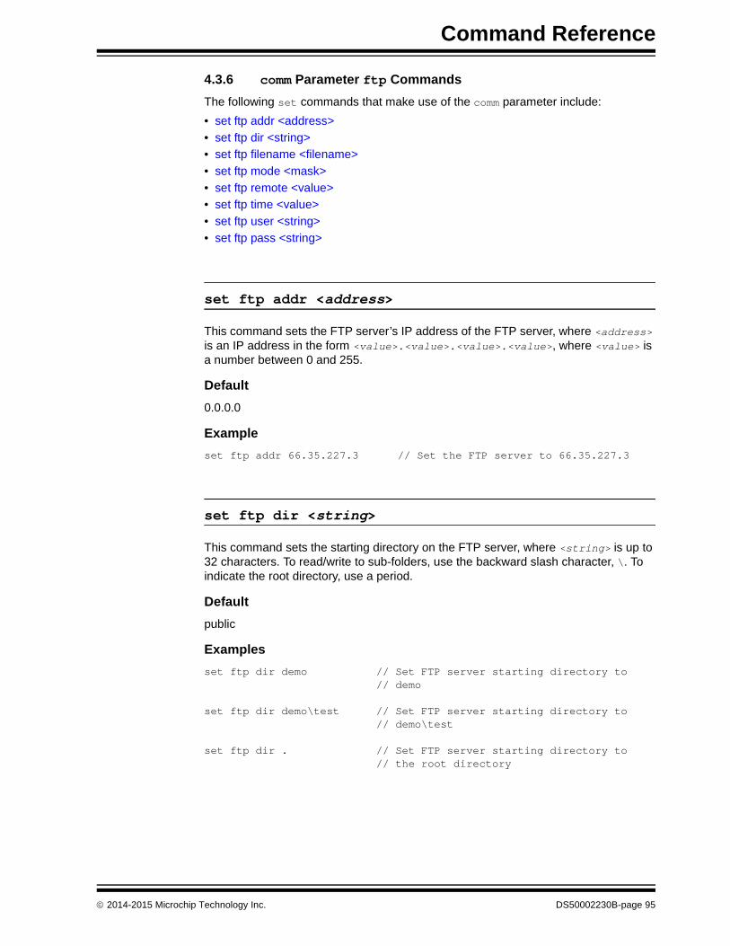
Command Reference
4.3.6 comm Parameter ftp Commands
The following set commands that make use of the comm parameter include:
• set ftp addr <address>
• set ftp dir <string>
• set ftp filename <filename>
• set ftp mode <mask>
• set ftp remote <value>
• set ftp time <value>
• set ftp user <string>
• set ftp pass <string>
set ftp addr <address>
This command sets the FTP server’s IP address of the FTP server, where <address> is an IP address in the form <value>.<value>.<value>.<value>, where <value> is a number between 0 and 255.
Default
0.0.0.0
Example
set ftp addr 66.35.227.3 // Set the FTP server to 66.35.227.3
set ftp dir <string>
This command sets the starting directory on the FTP server, where <string> is up to 32 characters. To read/write to sub-folders, use the backward slash character, \. To indicate the root directory, use a period.
Default
public
Examples
set ftp dir demo // Set FTP server starting directory to// demo
set ftp dir demo\test // Set FTP server starting directory to// demo\test
set ftp dir . // Set FTP server starting directory to// the root directory
2014-2015 Microchip Technology Inc. DS50002230B-page 95
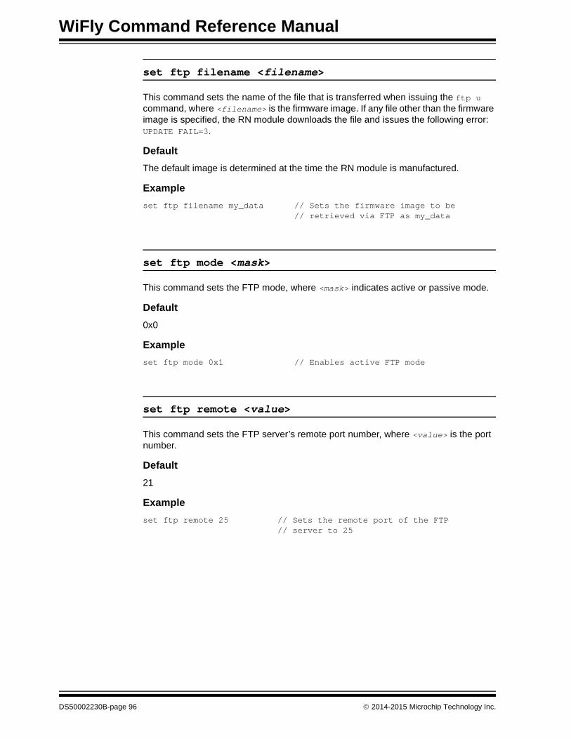
WiFly Command Reference Manual
set ftp filename <filename>
This command sets the name of the file that is transferred when issuing the ftp u command, where <filename> is the firmware image. If any file other than the firmware image is specified, the RN module downloads the file and issues the following error: UPDATE FAIL=3.
Default
The default image is determined at the time the RN module is manufactured.
Example
set ftp filename my_data // Sets the firmware image to be// retrieved via FTP as my_data
set ftp mode <mask>
This command sets the FTP mode, where <mask> indicates active or passive mode.
Default
0x0
Example
set ftp mode 0x1 // Enables active FTP mode
set ftp remote <value>
This command sets the FTP server’s remote port number, where <value> is the port number.
Default
21
Example
set ftp remote 25 // Sets the remote port of the FTP// server to 25
DS50002230B-page 96 2014-2015 Microchip Technology Inc.

Command Reference
set ftp time <value>
This command sets the FTP timeout value, where <value> is a decimal number that is five times the number of seconds required. The RN module uses this timer to close the FTP connection automatically after the specified time.
Default
200
Examples
set ftp timer 40 // Sets a 5-second timer
set ftp timer 80 // Sets a 10-second timer
set ftp user <string>
This command sets the user name for accessing the FTP server, where <string> is up to 16 characters (16 bytes).
Default
roving
Example
set ftp user my_username // Sets the user name to my_username
set ftp pass <string>
This command sets the password for accessing the FTP server, where <string> is up to 16 characters (16 bytes).
Default
Pass123
Example
set ftp user my_password // Sets the user name to my_password
2014-2015 Microchip Technology Inc. DS50002230B-page 97

WiFly Command Reference Manual
4.3.7 ip Parameter set Commands
The following set commands that make use of the ip parameter include:
• set ip address <address>
• set ip backup <address>
• set ip dhcp <value>
• set ip flags <mask>
• set ip gateway <address>
• set ip host <address>
• set ip localport <value>
• set ip netmask <address>
• set ip protocol <flag>
• set ip remote <value>
• set ip tcp-mode <mask>
set ip address <address>
This command sets the RN module’s IP address, where <address> is an IP address in the form <value>.<value>.<value>.<value>,where <value> is a number between 0 and 255. If DHCP is turned on, the IP address is assigned and overwritten when the RN module associates with an access point. IP addresses are “.” delimited.
Default
0.0.0.0
Example
set ip address 10.20.20.1 // Sets the RN module’s IP// address to 10.20.20.1
set ip backup <address>
This command sets a secondary host IP address, where <address> is an IP address in the form <value>.<value>.<value>.<value>, where <value> is a number between 0 and 255. If the primary host IP is unreachable, the RN module attempts to reach the secondary IP address (if set).
Default
0.0.0.0
Example
set ip backup 10.20.20.2 // Sets the RN module’s secondary// IP address to 10.20.20.2
DS50002230B-page 98 2014-2015 Microchip Technology Inc.

Command Reference
set ip dhcp <value>
This command enables/disables DHCP mode, where <value> is a decimal number shown in Table 4-4. If this parameter is set, the RN module requests and sets the IP address, gateway, netmask, and DNS server upon association with an access point. Any previously set IP information is overwritten.
Using DHCP cache mode can reduce the time the RN module requires to wake from deep sleep, which saves power. The RN module checks the lease time; if it is not expired, the RN module uses the previous IP settings. If the lease has expired, the RN module attempts to associate and uses DHCP to obtain the IP settings. The DHCP cached IP address does not survive a power cycle or reset.
Default
1
Example
set ip dhcp 0 // Turns DHCP off
TABLE 4-4: DHCP MODES
Mode Protocol
0 Turns DHCP off. The RN module uses its stored static IP address.
1 Turns DHCP on. The RN module attempts to obtain an IP address and gateway from the access point.
2 Enables automatic IP, which is generally used on networks that do not have a DHCP server.
3 Turns on DHCP cache mode. The RN module uses a previously set IP address if the lease is not expired (or the lease survives reboot).
4 Enables DHCP server in Soft AP mode.
2014-2015 Microchip Technology Inc. DS50002230B-page 99

WiFly Command Reference Manual
set ip flags <mask>
This command sets the TCP/IP functions, where <mask> is a hex number referring to a bit-mapped register. See Figure 4-1.
FIGURE 4-1: SET IP FLAGS COMMAND BIT-MAPPED REGISTER
If bit 0 is set (default), TCP connections are kept open when the connection to the access point is lost.
If bit 0 is cleared by sending set ip flags 0x6, and if the RN module loses the access point connection while TCP is connected, the connection is closed.
Default
0x7
Example
set ip flags 0x6 // Clear bit 0
set ip gateway <address>
This command sets the gateway IP address, where <address> is an IP address in the form <value>.<value>.<value>.<value>, where <value> is a number between 0 and 255. If DHCP is turned on, the gateway IP address is assigned and overwritten when the RN module associates with the access point.
Default
0.0.0.0
Example
set ip gateway 169.254.1.1 // Sets the IP gateway to// 169.254.1.1
1234567 0
TCP connection status. See .
Bypass Nagle algorithm and use TCP_NODELAY.
TCP retry enabled (for a total of 96 packet retries).
UDP RETRY (attempts retry if no ACK from UDP).
DNS host address caching enabled.
ARP table caching enabled.
UDP auto pairing enabled.
Add 8-byte timestamp to UDP or TCP
Note 1: If the RN module loses the link to an associated access point while a TCP connection is active, the TCP connection may hang or be in an inconsis-tent state. In some cases, the TCP connection will not recover.
DS50002230B-page 100 2014-2015 Microchip Technology Inc.

Command Reference
set ip host <address>
This command sets the remote host’s IP address, where <address> is an IP address in the form <value>.<value>.<value>.<value>, where <value> is a number between 0 and 255. This command can be used to make connections from the RN module to a TCP/IP server with the IP address <address>.
Default
0.0.0.0
Example
set ip host 137.57.1.1 // Sets the remote host’s IP address to // 137.57.1.1
set ip localport <value>
This command sets the local port number, where <value> is a decimal number representing the port.
Default
2000
Example
set ip localport 1025 // Sets the local port to 1025
set ip netmask <address>
This command sets the network mask, where <address> is an IP address in the form <value>.<value>.<value>.<value>, where <value> is a number between 0 and 255. If DHCP is turned on, the netmask is assigned and overwritten when the RN module associates with the access point.
Default
255.255.255.0
Example
set ip netmask 255.255.0.0 // Sets the netmask to 255.255.0.0
2014-2015 Microchip Technology Inc. DS50002230B-page 101

WiFly Command Reference Manual
set ip protocol <flag>
This command sets the IP protocol, where <flag> is a bit-mapped register as shown in Figure 4-2. To connect to the RN module over TCP/IP (for example using Telnet), bit 2 of the IP protocol register must be set. For the RN module to accept both TCP and UDP, set bits 1 and 2 (value = 3).
FIGURE 4-2: SET IP PROTOCOL COMMAND BIT-MAPPED REGISTER
Default
2
Example
set ip protocol 18 // Enables TCP and HTTP client mode
set ip remote <value>
This command sets the remote host port number, where <value> is a decimal number representing the port.
Default
2000
Example
set ip remote 1025 // Sets the remote host port to 1025
1234 0
UDP.
TCP server and client (default).
Secure mode (only receive packets fr m IP address that matches the stored ost IP).
TCP client only.
HTTP client mode.
DS50002230B-page 102 2014-2015 Microchip Technology Inc.

Command Reference
set ip tcp-mode <mask>
This command controls the TCP connect timers, DNS preferences, and remote configuration options. <mask> is a hex number referring to a bit-mapped register, as shown in Figure 4-3.
FIGURE 4-3: SET IP TCP MODE COMMAND BIT-MAPPED REGISTER
Default
0x0
Examples
set ip tcp-mode 0x4 // Forces the RN module to use DNS
set ip tcp-mode 0x10 // Disables remote configuration
1234 0
Shorten the TCP connect timer (use with bit 1).
Shorten the TCP connect timer (use with bit 0).
Forces the module to use DNS first to resolve the IP address even if the ost IP is set
Reserved.
Disables remote configuration for security purposes.
2014-2015 Microchip Technology Inc. DS50002230B-page 103

WiFly Command Reference Manual
4.3.8 opt Parameter set Commands
The following set commands that make use of the opt parameter include:
• set opt jointmr <value>
• set opt format <flag>
• set opt replace <value>
• set opt deviceid <string>
• set opt password <string>
• set opt average <value>
• set opt signal <value>
set opt jointmr <value>
This command sets the join timer, which is the length of time (in ms) the join function waits for the access point to complete the association process. <value> is a decimal number representing the number of ms. This timer is also used as the time-out for the WPA handshaking process.
Default
1000
Example
set opt jointmr 1050 // Sets the join timer to 1,050 ms
DS50002230B-page 104 2014-2015 Microchip Technology Inc.

Command Reference
set opt format <flag>
The command sets the HTTP Client/Web Server information, where <flag> is a bit-mapped register as shown in Figure 4-4. Refer to Section 3.6 “Using the HTML Client Feature” for details.
FIGURE 4-4: SET OPT FORMAT COMMAND BIT-MAPPED REGISTER
Default
0x00
Example
set opt format 0x7 // Module sends sensor values
set opt replace <value>
This command sets the replacement character used to indicate spaces in the SSID and passphrase’s string, where <value> is the ASCII value of the character. Each occurrence of the replacement character is changed into a space. Only the WiFly command parser uses this replacement character.
For example, to change the replace character to the percent sign, %, use the set opt replace 0x25 command (the ASCII value of % is 0x25).
Default
0x24
Example
set opt replace 0x25 // Sets the replacement character to %
4 3 2 1 0
Automatically send an HTML header-based broadcast intervalSend binary data (converted to ASCII hex)
Sample the GPIO and ADC pins and format to ASCII hex
Appends &id=<value>, where <value> is the device ID string set using
Appends the following key/value pairs to the HTTP message:set opt device <string>
• &rtc=<time>• &mac=<address>• &bss=<access point address>• &bat=<battery voltage>• &io=<GPIO in hex>• &wake=<wake reason>• &seq=<sequence value>
where, <time> is the real-time clock value in the message of a 32-bit hex value in the format aabbccddeeff and <sequence value> is a rolling counter of how many web posts have been sent.
2014-2015 Microchip Technology Inc. DS50002230B-page 105

WiFly Command Reference Manual
set opt deviceid <string>
This command sets the configurable device ID, where <string> can be up to 32 bytes in length. The <string> can be used for serial numbers, a product name, or to show other device information. The RN module sends the device ID as part of the UDP broadcast hello packet. The current device ID value can be viewed using either the get option or show deviceid commands.
Default
WiFly-GSX
Example
set opt deviceid my_wifly // Sets the device ID to my_wifly
set opt password <string>
This command sets the TCP connection password, where <string> can be up to 32 bytes in length. This setting provides minimal authentication by requiring any remote device that connects to the RN module to send and match the challenge <string>. When a connection is opened, the RN module sends the string PASS? to the remote host. The remote host must reply with the exact characters that match the stored password in one TCP packet; otherwise, the RN module closes the connection. To disable the password feature, use ‘0’ (the default).
Default
“” (no password required)
Example
set opt password my_password // Sets the TCP connection// password to my_password
set opt average <value>
This command sets the number of RSSI samples used to calculate the running RSSI average for the set opt signal command.
Default
5
Example
set opt average 10 // Sets the average to 10 RSSI readings
DS50002230B-page 106 2014-2015 Microchip Technology Inc.

Command Reference
set opt signal <value>
This command enables the configuration of the threshold level for the RSSI value in Infrastructure mode. If the signal strength (RSSI) falls below <value> dB, the RN module declares Soft AP is lost and deauthenticates itself from the network. Thereafter, the RN module associates with the network based on the join policy.
This command is useful for applications in which the Wi-Fi module is in a mobile environment and frequently enters and leaves the Soft AP’s range.
The recommended range for <value> is between 50 and 80. As <value> is lowered, the RN module more frequently deauthenticates itself from the Soft AP.
Default
0
Example
set opt signal 70 // Sets the RSSI threshold to -70 dBm. If // the RSSI average falls below -70 dBm, // the RN module deauthenticates itself
Note: This command applies in infrastructure mode only. It is not applicable in Soft AP mode. For this feature to work properly, the link monitor must be enabled by the user.
2014-2015 Microchip Technology Inc. DS50002230B-page 107

WiFly Command Reference Manual
4.3.9 q Parameter set Commands
The following set commands that make use of the q parameter include:
• set q sensor <mask>
• set q power <value>
set q sensor <mask>
This command specifies which sensor pins to sample when sending data using the UDP broadcast packet or the HTTP auto sample function, where <mask> is a bit-mapped register.
Default
0
Example
set q sensor 0xff // Enables all sensor inputs
DS50002230B-page 108 2014-2015 Microchip Technology Inc.

Command Reference
set q power <value>
This register automatically turns on the sensor power, where <value> is shown in Table 4-5. This parameter sets an 8-bit register with two 4-bit nibbles. If the top nibble is set, power is applied upon power-up and removed upon power down or sleep. If the bottom nibble is set, power is applied when a sampling event occurs such as:
• UDP broadcast
• Automatic web posting of sensor data
• Power is removed immediately after sampling is complete
Default
0
Examples
set q power 0x20 // Sets power to 1.2V automatically // upon power-up
set q power 0x02 // Sets power to 1.2V when a // sampling event occurs
set q power 0x40 // Sets power to 3.3V automatically // upon power-up
set q power 0x04 // Sets power to 3.3V when a // sampling event occurs
TABLE 4-5: SET Q POWER COMMAND SENSOR PIN VOLTAGE SETTINGS
Value Sensor Pin Voltage
0 Turn off the sensor power.
1 Ground the sensor pin.
2 1.2V internal regulated reference.
3 VBATT input pin.
4 3.3V output of on board regulator.
2014-2015 Microchip Technology Inc. DS50002230B-page 109

WiFly Command Reference Manual
4.3.10 sys Parameter set Commands
The following set commands that make use of the sys parameter include:
• set sys autoconn <value>
• set sys iofunc <mask>
• set sys launch_string <string>
• set sys mask <mask>
• set sys printlvl <value>
• set sys output <mask> <mask>
• set sys sleep <value>
• set sys trigger <flag> or <mask>
• set sys value <mask>
• set sys wake <value>
• set sys z <value>
set sys autoconn <value>
This command sets the auto-connect timer in TCP mode, where <value> is a decimal number from 0 to 255, as shown in Table 4-6. Setting this parameter causes the RN module to connect to the stored remote host periodically as specified by <value>.
Default
0
Example
set sys autoconn 5 // The RN module connects to the host// every 5 seconds
Note: To use the auto-connect timer, the remote host’s IP address and port must be stored in the RN module using the set ip host <address> and set ip remote <value> commands.
TABLE 4-6: AUTO-CONNECT TIMER SETTINGS
Value Description
0 Disable the auto-connect timer (default).
1 Connect to the stored remote host immediately upon power-up or when waking from sleep.
2-254 Connect to a stored remote host every <value> seconds.
255 Connect to a stored host immediately upon power-up or when waking from sleep and go back to sleep immediately as soon as the TCP connection closes.
DS50002230B-page 110 2014-2015 Microchip Technology Inc.
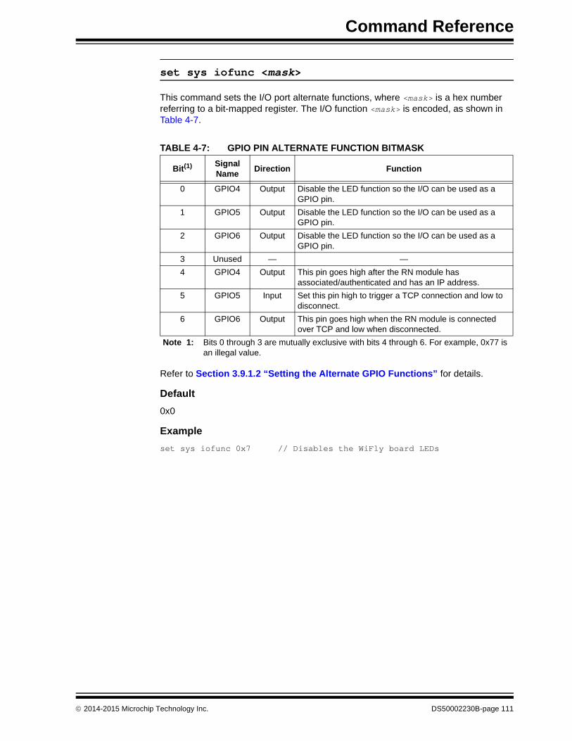
Command Reference
set sys iofunc <mask>
This command sets the I/O port alternate functions, where <mask> is a hex number referring to a bit-mapped register. The I/O function <mask> is encoded, as shown in Table 4-7.
Refer to Section 3.9.1.2 “Setting the Alternate GPIO Functions” for details.
Default
0x0
Example
set sys iofunc 0x7 // Disables the WiFly board LEDs
TABLE 4-7: GPIO PIN ALTERNATE FUNCTION BITMASK
Bit(1) Signal Name
Direction Function
0 GPIO4 Output Disable the LED function so the I/O can be used as a GPIO pin.
1 GPIO5 Output Disable the LED function so the I/O can be used as a GPIO pin.
2 GPIO6 Output Disable the LED function so the I/O can be used as a GPIO pin.
3 Unused — —
4 GPIO4 Output This pin goes high after the RN module has associated/authenticated and has an IP address.
5 GPIO5 Input Set this pin high to trigger a TCP connection and low to disconnect.
6 GPIO6 Output This pin goes high when the RN module is connected over TCP and low when disconnected.
Note 1: Bits 0 through 3 are mutually exclusive with bits 4 through 6. For example, 0x77 is an illegal value.
2014-2015 Microchip Technology Inc. DS50002230B-page 111

WiFly Command Reference Manual
set sys launch_string <string>
This command sets the name of the application (indicated by <string>) that is launched when GPIO9 toggles from high-to-low after power-up (by pressing the FN button on an evaluation kit). This mechanism is used to launch valid applications, as shown in Table 4-8.
Setting the <string> to an invalid string such as test results in the following error message when the GPIO9 pin is toggled: *test not Found*
Default
web_app
Example
set sys launch_string wps_app // Sets the launch application// to WPS
TABLE 4-8: VALID APPLICATION STRINGS
<string> Description
web_app Launches the configuration Web Server.
wps_app Launches the WPS application.
Note: Do not set <string> to the configuration filename or the boot firmware image. Otherwise, the RN module configuration may become corrupted and the RN module will reboot.
Note: Disable this error message by setting the print level to zero using the set sys print 0 command.
DS50002230B-page 112 2014-2015 Microchip Technology Inc.

Command Reference
set sys mask <mask>
This command sets the I/O port direction, where <mask> is a hex number referring to a bit-mapped register. Figure 4-5 shows the bits corresponding to the GPIO pins and Table 4-9 shows the GPIO pin usage, their default state, and functionality.
FIGURE 4-5: GPIO PIN BITMASK
TABLE 4-9: GPIO PIN USAGE, DEFAULT STATE AND FUNCTIONALITY
BitSignal Name
Module Default State Default Function
RN131RN171/RN1723
0 GPIO0 N/A N/A Unused.
1 GPIO1 N/A Input Unused.
2 GPIO2 N/A Input Unused.
3 GPIO3 N/A Input Unused.
4 GPIO4 Output Output Green LED.
5 GPIO5 Output Output Yellow LED.
6 GPIO6 Output Output Red LED.
7 GPIO7 Output Output Blue LED.
8 GPIO8 Input Output Unused.
9 GPIO9 Input Input Soft AP mode and factory reset.
10 GPIO10 Output Output UART TX.
11 GPIO11 Input Input UART RX.
12 GPIO12 Input Input Throttles the transmitter if hardware flow control is enabled. Driving this pin low enables transmitter; driving this pin high disables it.
13 GPIO13 Output Output This pin goes high on power-up and goes low when the system is ready. If hardware flow control is enabled, this pin toggles to high to indicate the RX buffer is full.
14 GPIO14 N/A Input Unused.
14 13 12 11 10 9 8 7 6 5 4 3 2 1 0GPIO0
GPIO1
GPIO2
GPIO3
GPIO4
GPIO5
GPIO6
GPIO7
GPIO14
GPIO13 UART RTS
GPIO12 UART CTS
GPIO11 UART RX
GPIO10 UART TX
GPIO9
GPIO8
Note: On the RN174 evaluation board, the blue LED is connected to GPIO7. The blue LED is NOT connected to GPIO7 on the RN134 evaluation board. It is not possible to power off the blue LED on the RN134 board because it is connected directly to power.
2014-2015 Microchip Technology Inc. DS50002230B-page 113

WiFly Command Reference Manual
Refer to Section 3.9.1 “Setting GPIO Direction, Alternate Functions, and Disabling LEDs” for details.
Default
0x20F0 (RN131 module)
0x21F0 (RN171/RN1723 module)
Example
set sys mask 0x0 // Sets all pins as inputs
set sys printlvl <value>
This command controls the debug print messages printed by the RN module on the UART, where <value> is one of the values shown in Table 4-10. Refer to Section 3.10 “Setting Debug Print Levels” for more information.
Default
0x1
Example
set sys printlvl 2 // Sets the debug print messages to only // critical network connection status
Note: To set the GPIO pins as inputs or outputs instantly, use the set sys mask 0xABCD 1 command, which does not require a reboot.
TABLE 4-10: DEBUG PRINT MESSAGE SETTINGS
Value Description
0 Quiet mode. Messages are not printed when the RN module wakes up or powers up.
1 Print all status messages.
2 Print only critical network access point connection level status. For example, Associated! or Disconnect from <SSID>.
4 Print the DHCP and IP address status information. After verifying the RN module’s configuration, this option can be turned off so that the messages do not interfere with the data.
0x4000 Change the scan format output to a MCU-friendly format.
0x10 Enables the UART heartbeat message. Refer to Section 3.10.2 “UART Heartbeat Messages” for details.
DS50002230B-page 114 2014-2015 Microchip Technology Inc.

Command Reference
set sys output <mask> <mask>
This command sets the output GPIO pins high or low, where <mask> is a hex number referring to a bit-mapped register. The optional <mask> sets a subset of the pins.
Default
None
Example
To toggle GPIO8, use the following commands:
set sys mask 0x21f0 // Set GPIO8 as outputset sys output 0x0100 0x0100 // Drives GPIO8 highset sys output 0x0000 0x0100 // Drives GPIO8 low
set sys sleep <value>
This command sets the sleep timer, where <value> is a decimal number. The sleep timer is the time (in seconds) after which the RN module goes to sleep. This timer is disabled during an open TCP connection. When the TCP connection is closed, the RN module counts down and puts the RN module to sleep after <value> seconds. Setting the value to ‘0’ disables the sleep timer, and the RN module will not go to sleep based on this counter.
Refer Section 3.5.2 “System and Auto-Connect Timers” for more information on using system timers.
Default
0
Example
set sys sleep 5 // Module sleeps 5 seconds after the TCP // connection closes
Note: Be sure to set the wake timer before issuing the sleep timer if an external wake-up signal is not used; otherwise, the RN module will never wake up.
2014-2015 Microchip Technology Inc. DS50002230B-page 115

WiFly Command Reference Manual
set sys trigger <flag> or <mask>
With this parameter setting, the RN module wakes from the sleep state using the sensor input 0, 1, 2, and 3, where <flag> is a decimal number referring to a bit-mapped register as shown in Table 4-11 and <mask> is a hex number. Either <flag> or <mask> can be used with this parameter setting. This command sets the sensor input(s) to wake on (0 to 3). Setting <flag> to ‘0’ disables wake on sensor inputs.
Table 4-12 describes how to wake the RN module using sensor input.
Setting the trigger value to 0x20 (i.e., using <mask>) puts the RN module to sleep when GPIO8 is pulled high. To enable this feature, use the set sys trigger 0x20 command. This command makes GPIO8 an interrupt pin and puts the RN module to sleep as soon as it is pulled high, regardless of the RN module’s state; the RN module goes to sleep even if it is associating with a network or has an open, active TCP connection.
This command is useful for when the RN module is failing to associate with network because it is out of range (or for any other reason), or if the RN module must be put to sleep quickly.
Default
0x41
Example
set sys trigger 0x8 // Enable wake on sensor input 3
TABLE 4-11: SET SYS TRIGGER COMMAND BIT-MAPPED REGISTER
Bit Position Description
0 Trigger sensor input 0.
1 Trigger sensor input 1.
2 Trigger sensor input 2.
3 Trigger sensor input 3.
5 Enable sleep on GPIO8.
TABLE 4-12: SENSOR INPUT TRIGGER VALUES
Wake on Sensor Input Value Command
0 1 set sys trigger 1
1 2 set sys trigger 2
2 4 set sys trigger 4
3 8 set sys trigger 8
Note: The GPIO8 pin must be low on power-up and remain low until the time the RN module is to be put to sleep.
DS50002230B-page 116 2014-2015 Microchip Technology Inc.

Command Reference
set sys value <mask>
This command sets the default value of the GPIO pins’ outputs upon power-up, where <mask> is a hex number representing a bit-mapped register. The GPIO pins that are configured as outputs can be driven high or low on power-up or when the RN module wakes from sleep. The default power-up states can be set ONLY for the GPIO pins that are set as outputs. Setting the value to ‘1’ makes the default power-up state high; setting the value to ‘0’ makes the default power-up state low.
To configure GPIO pins as outputs, use the set sys mask <value> command.
Default0x0
Example
To configure power-up states of GPIO8 (output by default):
set sys value 0x0100 // Sets GPIO8 high upon power-upset sys value 0x0000 // Sets GPIO8 low upon power-up
set sys wake <value>
This command sets the automatic wake timer, where <value> is a decimal number representing the number of seconds after which the RN module wakes from sleep. Setting <value> to ‘0’ disables it. Refer to Section 3.5.2 “System and Auto-Connect Timers” for additional information.
Default
0
Example
set sys wake 5 // The RN module wakes after 5 seconds
set sys z <value>
This command sets the minimum doze time for the CPU when there is no work to be done. This is power-saving feature that enables the RN module to consume less power whenever there is no data to process.
Default
0
Example
set sys z 5 // Set the minimum processor doze time to 5 ms
Note: GPIO pins 4, 5, and 6 are used by the firmware to blink the status LEDs. To set the default power-up states for these GPIO pins, their use must first be disabled by the firmware using the set sys iofunc 0x7 command.
Note: This command is only available on RN1723 modules.
2014-2015 Microchip Technology Inc. DS50002230B-page 117

WiFly Command Reference Manual
4.3.11 time Parameter set Commands
The following set commands that make use of the time parameter include:
• set time address <address>
• set time port <value>
• set time enable <value>
• set time raw <value>
set time address <address>
This command sets the time server address, where <address> is an IP address in the form <value>.<value>.<value>.<value>, where <value> is a number between 0 and 255. This command applies to SNTP servers.
Default
64.90.182.55
Example
set time address 208.109.78.52 // Sets the time server// address to 208.109.78.52
set time port <value>
This command sets the time server port number, where <value> is a decimal number. The default value of 123 is typically the SNTP server port.
Default
123
Example
set time port 1052 // Sets the time server port to 1052
set time enable <value>
This parameter tells the RN module how often to fetch the time from the specified SNTP time server, where <value> is a decimal number representing minutes. The default (0) disables time fetching. If <value> is ‘1’, the RN module fetches the time only once on power-up. If <value> is greater than ‘1’, the RN module fetches the time every <value> minutes.
Default
0
Example
set time enable 5 // The RN module fetches the time every // 5 minutes
DS50002230B-page 118 2014-2015 Microchip Technology Inc.

Command Reference
set time raw <value>
This parameter setting enables the RTC raw value to be set from the console, where <value> is a decimal number in seconds. The RTC counts at 32,768 Hz.
Default
None
Example
set time raw 1 // Set the RTC raw value to 1 second
2014-2015 Microchip Technology Inc. DS50002230B-page 119

WiFly Command Reference Manual
4.3.12 uart Parameter set Commands
The following set commands that make use of the uart parameter include:
• set uart baud <value>
• set uart cmdgpio <value>
• set uart flow <value>
• set uart instant <value>
• set uart mode <mask>
• set uart raw <value>
• set uart tx <value>
set uart baud <value>
This command sets the UART baud rate, where <value> can be: 2400, 4800, 9600, 19200, 38400, 57600, 115200, or 230400.
Default
9600
Example
set uart baud 19200 // Sets the baud rate to 19,200
set uart cmdgpio <value>
This command allows the RN module to be placed into Command mode by asserting the GPIO1 pin.
Default
0
Example
set uart cmdgpio 1 // Enables GPIO1 pin asserts to enter the // RN module into Command mode
Note: The RN174 evaluation board’s RS-232 interface cannot exceed 230,400 baud.
Note: This command is only available on RN1723 modules.
DS50002230B-page 120 2014-2015 Microchip Technology Inc.

Command Reference
set uart flow <value>
This command sets the flow control mode and parity, where <value> is a hex number. The setting is in the upper nibble of the hardware flow control setting. The default is flow control disabled with parity set to None/No parity. Figure 4-6 shows the bit-mapped register.
FIGURE 4-6: SET UART FLOW BIT-MAPPED REGISTER
Default
0
Examples
set uart flow 0x21 // Even parity with flow control
set uart flow 0x20 // Even parity without flow
set uart flow 0x31 // Odd parity with flow control
set uart flow 0x30 // Odd parity without flow control
Flow control:
0 = Disabled1 = EnabledParity:
00 = None01 = Illegal10 = Even11 = Odd
1234567 000 00 0
Note: Once flow control is enabled, it is important to drive the CTS pin properly (i.e., active-low enabled). If CTS is high, the RN module does not send data through the UART and further configuration in Command mode is problematic because no response is received.
2014-2015 Microchip Technology Inc. DS50002230B-page 121

WiFly Command Reference Manual
set uart instant <value>
This command immediately changes the baud rate, where <value> can be: 2400, 4800, 9600, 19200, 38400, 57600, 115200, or 230400. This command is useful when testing baud rate settings or when switching the baud rate “on-the-fly” while connected over TCP via Telnet. Using this command does not affect configuration. The RN module returns the AOK response, and then the RN module exits Command mode.
If used in Local mode, the baud rate changes and the RN module sends AOK using the new baud rate. If the host switches to the new baud rate immediately, the host may see the AOK string at the new baud rate. Depending on the baud rate, it takes at least ten times the bit rate for the RN module to issue the first character.
Default
Not applicable
Example
set uart instant 19200 // Sets the baud rate to 19,200
Note: The RN module does not return an AOK over Telnet before exiting Command mode.
DS50002230B-page 122 2014-2015 Microchip Technology Inc.

Command Reference
set uart mode <mask>
This command sets the UART mode register, where <mask> is a hex number masking a bit-mapped value as shown in Figure 4-7.
FIGURE 4-7: SET UART MODE COMMAND BIT-MAPPED REGISTER
Default
0
Example
set uart mode 0x10 // Enable the UART data buffer
Command echo:
0 = Enabled1 = Disabled
Data trigger:
0 = Disabled1 = Make TCP connection upon UART RX data
1234567 000 0
Sleep on RX break signal:
0 = Disabled1 = Enabled
UART RX data buffer:
0 = When TCP connection closes, buffer is flushed1 = When TCP connection closes, buffer holds data until: - If more data is received, buffer is flushed - If no data is received and a new connection is made, buffer is transmitted
Command prompt:
0 = Version string <x.xx>1 = Replacement character
2014-2015 Microchip Technology Inc. DS50002230B-page 123

WiFly Command Reference Manual
set uart raw <value>
This command sets a raw UART value, where <value> is a decimal number representing the baud rate. This command can be used to set non-standard baud rates. The lowest possible baud rate is 2,400.
Using non-standard raw baud rates with hardware flow control can be more useful at high speeds as the microcontroller interfaced to the RN module may be able to better match the UART speed and get better results. Table 4-13 shows the supported raw baud rates.
Default
Not applicable
Example
set uart raw 7200 // Sets the baud rate to 7,200
set uart tx <value>
This command disables or enables the UART’s TX pin (GPIO10), where <value> is ‘1’ or ‘0’. Disabling the pin (<value> = 0) sets GPIO10 as an input with a weak pull-down.
Default
Not Applicable
Example
set uart tx 1 // Enable the UART’s TX pin
TABLE 4-13: SUPPORTED RAW BAUD RATES
Raw Baud Rate Comment
458,333 This is 460,800.
500,000 Raw baud rate.
550,000 Raw baud rate.
611,111 Raw baud rate.
687,599 Raw baud rate.
785,714 Raw baud rate.
916,667 This is 921,600.
1,100,000 Raw baud rate.
DS50002230B-page 124 2014-2015 Microchip Technology Inc.
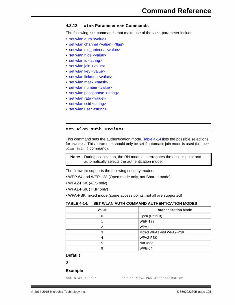
Command Reference
4.3.13 wlan Parameter set Commands
The following set commands that make use of the wlan parameter include:
• set wlan auth <value>
• set wlan channel <value> <flag>
• set wlan ext_antenna <value>
• set wlan hide <value>
• set wlan id <string>
• set wlan join <value>
• set wlan key <value>
• set wlan linkmon <value>
• set wlan mask <mask>
• set wlan number <value>
• set wlan passphrase <string>
• set wlan rate <value>
• set wlan ssid <string>
• set wlan user <string>
set wlan auth <value>
This command sets the authentication mode. Table 4-14 lists the possible selections for <value>. This parameter should only be set if automatic join mode is used (i.e., set wlan join 2 command).
The firmware supports the following security modes:
• WEP-64 and WEP-128 (Open mode only, not Shared mode)
• WPA2-PSK (AES only)
• WPA1-PSK (TKIP only)
• WPA-PSK mixed mode (some access points, not all are supported)
Default
0
Example
set wlan auth 4 // Use WPA2-PSK authentication
Note: During association, the RN module interrogates the access point and automatically selects the authentication mode.
TABLE 4-14: SET WLAN AUTH COMMAND AUTHENTICATION MODES
Value Authentication Mode
0 Open (Default)
1 WEP-128
2 WPA1
3 Mixed WPA1 and WPA2-PSK
4 WPA2-PSK
5 Not used
8 WPE-64
2014-2015 Microchip Technology Inc. DS50002230B-page 125

WiFly Command Reference Manual
set wlan channel <value> <flag>
This command sets the WLAN channel, where <value> is a decimal number from 1 to 13 representing a fixed channel and <flag> is the optional character i (meaning immediate). If the channel is set to ‘0’, the RN module performs a scan using the SSID for all of the channels set in the channel mask. The i flag allows the creation of a temporary Soft AP mode setup without having to reboot or save the settings (see Example 2).
Default
0
Example 1
set wlan channel 2 // Set the WLAN channel to 2
Example 2
set wlan channel 1 iset wlan join 7set ip address 1.2.3.4set ip gateway 1.2.3.4set ip netmask 255.255.255.0set ip dhcp 4 // Use DHCP serverjoin <SSID> // Module goes into Soft AP mode
set wlan ext_antenna <value>
This command determines which antenna is active, where <value> is ‘0’ (use the chip antenna) or ‘1’ (use the U.FL connector). Only one antenna is active at a time and the RN module must be power cycled after changing the antenna setting.
Default
0
Example
set wlan ext_antenna 1 // Use the U.FL antenna
Note: This command applies only to the RN131 module; it is not applicable to the RN171/RN1723 module. Sending this parameter to the RN171/RN1723 module results in the error message: ERR: Bad Args.
DS50002230B-page 126 2014-2015 Microchip Technology Inc.

Command Reference
set wlan hide <value>
This command hides the WEP key and WPA passphrase, where <value> is ‘0’ or ‘1’. If this parameter is set to ‘0’, the passphrase or pass key is displayed. If this parameter is set to ‘1’, the RN module shows ****** for these fields when displaying the WLAN settings. To show the passphrase or pass key, re-enter the key or passphrase using the set wlan key or set wlan passphrase command.
Default
0
Example
set wlan hide 1 // Hide the passphrase or pass key
set wlan id <string>
This command sets the EAP ID. This command is reserved for future development and is unused.
set wlan join <value>
This command sets the policy for automatically associating with network access points, where <value> is one of the options shown in Table 4-15. the RN module uses this policy on power-up, including waking up from the sleep timer.
Default
0
Example
set wlan join 7 // Create a Soft AP network
TABLE 4-15: SET WLAN JOIN COMMAND OPTIONS
Value Policy
0 Manual. Do not try to associate with a network automatically.
1 Try to associate with the access point that matches the stored SSID, pass key, and channel. If the channel is set to ‘0’, the RN module will scan for the access point. (default)
2 Associate with ANY access point that has security matching the stored authentica-tion mode. the RN module ignores the stored SSID and searches for the access point with the strongest signal. The channels that are searched can be limited by setting the channel mask.
3 Reserved.
7 Create a Soft AP network using the stored SSID, IP address, netmask, channel, etc. This mode applies only to firmware versions supporting Soft AP mode.
2014-2015 Microchip Technology Inc. DS50002230B-page 127

WiFly Command Reference Manual
set wlan key <value>
This command sets the WEP-64 or WEP-128 key, where <value> is exactly 26 ASCII chars (13 bytes) in hex without the preceding 0x. Hex digits greater than none can be either uppercase or lowercase. If WPA or WPA2 is used, enter a passphrase with the set wlan passphrase command.
The WEP key length depends on the WEP security used (WEP-64 or WEP-128):
• WEP-64 uses a 10-character key
• WEP-128 uses a 26-character key
Default
00 00 00 00 00
Example
set wlan key 112233445566778899AABBCCDD // Sets the WEP key
set wlan linkmon <value>
This parameter is used in Infrastructure mode to detect whether the RN module is associated and in range of the access point.
This command sets the infrastructure mode link monitor timeout threshold, where <value> is a decimal number representing the number of failed scans before the RN module declares Lost-Soft AP and deauthenticates (e.g., when the RN module goes out of the access point’s range). Setting this parameter to ‘1’ or more causes the RN module to scan once per second for the access point with which it is associated.
If the RN module deauthenticates itself from the access point using the link monitor, it reattempts the association based on the join policy setting.
Microchip recommends setting the threshold to 30 attempts, because some access points do not always respond to probes. If this parameter is not set, there is no way to detect that an access point is no longer present until it becomes available again (if ever).
To disable the link monitor, set <value> to zero (0).
Default
30
Example
set wlan linkmon 5 // Set the number of scan attempts to 5
DS50002230B-page 128 2014-2015 Microchip Technology Inc.

Command Reference
set wlan mask <mask>
This command sets the WLAN channel mask, which is used for scanning channels with auto-join policy 1 or 2, where <mask> is a hex number (bit 0 = channel 1). Reducing the number of channels scanned for association increases battery life. This setting is used when the channel is set to ‘0’.
Default
0x1FFF (all channels)
Example
set wlan mask 0x0421 // Scans for channels 1, 6, and 11
set wlan number <value>
This command sets the WEP key number. The WEP key number must match the key number on the router or access point. It is only necessary to set this parameter when using the WEP-64 or WEP-128 security modes. This setting is not required if the WPA security mode is being used.
Default
0
Example
set wlan number 1 // Sets the WEP key number to 1
set wlan passphrase <string>
This command sets the passphrase for WPA and WPA2 security modes, where <string> is 1 to 64 characters (64 bytes). The passphrase is alphanumeric, and is used with the SSID to generate a unique 32-byte Pre-Shared Key (PSK), which is then hashed into a 256-bit number. When either the SSID or the passphrase is changed, the RN module recalculates and stores the PSK.
If exactly 64 characters are entered, the RN module assumes that the passphrase is an ASCII hex representation of the 32-byte PSK, and the value is simply stored.
For passphrases that contain spaces, use the replacement character $ instead of spaces. For example, my pass word becomes my$pass$word. The replacement character can be changed using the set opt replace command.
Default
rubygirl
Example
set wlan passphrase my_password // Sets the passphrase to// my_password
2014-2015 Microchip Technology Inc. DS50002230B-page 129

WiFly Command Reference Manual
set wlan rate <value>
This command sets the wireless data rate, where <value> is one of the options shown in Table 4-16. Lowering the data rate increases the effective range of the RN module.
Default
12
Example
set wlan rate 13 // Set the data rate to 36 Mbps
set wlan ssid <string>
This command sets the SSID with which the RN module associates, where <string> is 1 to 32 characters (32 bytes).
Default
roving1
Example
set wlan ssid my_network // Set the SSID to my_network
TABLE 4-16: SET WLAN RATE COMMAND OPTIONS
Value Wireless Data Rate (Mbits/second)
0 1
1 2
2 5.5
3 11
4-7 Invalid
8 6
9 9
10 12
11 18
12 24 (default)
13 36
14 48
15 54
Note: The <string> cannot contain spaces. If the SSID has spaces, use the dollar sign character, $, to indicate the space. For example, an SSID of Data Server, becomes Data$Server. When using the get wlan command to view the SSID, the RN module will properly displays it as: SSID=data server.
DS50002230B-page 130 2014-2015 Microchip Technology Inc.

Command Reference
set wlan tx <value>
This command sets the Wi-Fi transmit power, where <value> is a decimal number from 1 to 12 that corresponds to 1 to 12 dBm. The default, 0, corresponds to 12 dB, which is the maximum TX power. Setting the value to ‘0’ or ‘12’ sets the TX power to 12 dBm.
Default
0
Example
set wlan tx 11 // Set the TX power to 11 dBm
set wlan user <string>
This command is reserved for future development and is unused.
Note: This command applies only to the RN171 and RN1723 modules, and is not applicable to the RN131. The transmit power on the RN131 is fixed to 18 dBm. Sending this parameter to the RN131 results in the error message: ERR: Bad Args.
2014-2015 Microchip Technology Inc. DS50002230B-page 131

WiFly Command Reference Manual
4.4 GET COMMANDS
These commands begin with the keyword get and they display the RN module’s current values. Except where noted, the get commands do not have any parameters. Table 4-17 lists and briefly describes each command.
get apmode
This command displays the Soft AP mode settings.
Example
get apmode // Show Soft AP mode settings
get broadcast
This command displays the broadcast UPD address, port, and interval.
Example
get broadcast // Show broadcast UDP information
get com
This command displays the communication settings.
Example
get com // Show communication settings
TABLE 4-17: GET COMMANDS
Command Description
get apmode Displays the Soft AP mode settings.
get broadcast Displays the broadcast UPD address, port, and interval.
get com Displays the communication settings.
get dns Displays the DNS settings.
get everything Displays all of the configuration settings, which is useful for debugging.
get ftp Displays the FTP settings.
get ip <char> Displays the IP address and port number settings, where <char> is the optional parameter ‘a’. Using <char> returns the current IP address.
get mac Displays the device’s MAC address.
get option Displays the optional settings such as the device ID.
get sys Displays the system settings, sleep and wake timers, etc.
get time Displays the time server UDP address and port number.
get wlan Displays the SSID, channel, and other WLAN settings.
get uart Displays the UART settings.
ver Displays the firmware version.
DS50002230B-page 132 2014-2015 Microchip Technology Inc.

Command Reference
get dns
This command displays the DNS settings.
Example
get dns // Show the DNS information
get everything
This command displays all of the configuration settings, which is useful for debugging.
Example
get everything // Show all configuration settings
get ftp
This command displays the FTP settings.
Example
get ftp // Show the FTP settings
get ip <char>
This command displays the IP address and port number settings, where <char> is the optional parameter a. Using <char> returns the current IP address.
Example
get ip a // Display the current IP address
get mac
This command displays the device’s MAC address.
Example
get mac // Show the MAC address
2014-2015 Microchip Technology Inc. DS50002230B-page 133

WiFly Command Reference Manual
get option
This command displays the optional settings such as the device ID.
Example
get option // Show the optional settings
get sys
This command displays the system settings, sleep and wake timers, etc.
Example
get sys // Show the system settings
get time
This command displays the time server UDP address and port number.
Example
get time // Show the time server information
get wlan
This command displays the SSID, channel, and other WLAN settings.
Example
get wlan // Show the WLAN settings
get uart
This command displays the UART settings.
Example
get uart // Show the UART settings
ver
The command displays the firmware version.
Example
ver // Show the firmware version
DS50002230B-page 134 2014-2015 Microchip Technology Inc.

Command Reference
4.5 STATUS COMMANDS
These commands begin with the keyword show and return the current values of the sys-tem variables. In some cases, for example IP addresses, the current values are received from the network and may not match the stored values. Except where noted, the show commands do not have any parameters.
Table 4-18 lists and briefly describes each status command. Detailed descriptions of each command follow the table.
show connection
This command displays the connection status in the hex format 8<XYZ>, where 8<XYZ> is a bit-mapped register providing the information shown in Figure 4-8.
FIGURE 4-8: SHOW CONNECTION COMMAND BIT-MAPPED REGISTER
TABLE 4-18: STATUS COMMANDS
Command Description
show connection Displays the connection status in the hex format 8<XYZ>.
show io Displays the GPIO pins’ level status in the hex format 8<ABC>.
show net <char> Displays the current network status, association, authentication, etc., where <char> is the optional parameter ‘n’. Using the ‘n’ parameter displays only the MAC address of the access point with which the RN module is currently associated.
show q <value> Displays the value of the analog interface pin, where <value> is 0 to 7.
show q 0x1 <mask> Displays multiple analog interface values simultaneously.
show rssi Displays the last received signal strength.
show stats Displays the current statistics, packet RX/TX counters, etc.
show time Displays the number of seconds since the RN module was last powered up or rebooted.
4567 3..0
TCP status. 0 = idle; 1 = connected; 3 = No IP; 4 = connecting
Association. 1 = OK.
Authentication. 1 = OK.
DNS server. 1 = server is contacted.
DNS found. 1 = DNS is resolved.
12..9
Channel. Value = 1 - 13.
16..13
Fixed. Value = 8.
2014-2015 Microchip Technology Inc. DS50002230B-page 135

WiFly Command Reference Manual
show io
This command displays the level status of the GPIO pin in the hex format 8xxx. For example, 8103 indicates GPIO0, GPIO1, and GPIO8 are high.
Example
show io // Show the GPIO level status
show net <char>
The command displays the current network status, association, authentication, etc., where <char> is the optional parameter n. Using the n parameter displays only the MAC address of the access point with which the RN module is currently associated.
Example
show net n // Show the access point’s MAC address
show q <value>
This command displays the value of the analog interface pin, where <value> is 0 to 7. The analog-to-digital reading is 14 bits with a range of 0 to 400 mV (therefore, the resolution is 24 µV). The output is in µV (1,000 millivolts). the RN module returns a value in the format 8xxxxx, where ‘xxxxx’ is the voltage in microvolts sampled on the requested channel.
Example
show q 0 // Show the voltage on channel 0
show q 0x1<mask>
This command displays multiple analog interface values simultaneously, where <mask> is a bit-mask representing the channels. For example, to read channels 0, 1, and 7, use the command: show q 0x183. The RN module returns 8<chan0>, 8<chan1>, 8<chan7>.
Example
show q 0x183 // Show values for channel 0, 1, and 7
Note: If a web post or UDP broadcast samples the data, the data is shifted, as described in Section 3.5.4.3 “UDP Broadcast”.
Note: If a web post or UDP broadcast samples the data, the data is shifted, as described in Section 3.5.4.3 “UDP Broadcast”.
DS50002230B-page 136 2014-2015 Microchip Technology Inc.

Command Reference
show rssi
This command displays the last received signal strength.
Example
show rssi // Show signal strength
show stats (Only available on RN131 and RN171 modules)
This command displays the current statistics, packet RX/TX counters, etc. The command returns the statistics shown in Table 4-19.
Example
show stats // Show the statistics
show time
This command displays the number of seconds since the RN module was last powered up or rebooted.
Example
show time // Show the number of seconds elapsed since// the last power-up
TABLE 4-19: DISPLAY STATISTICS
Statistic Description
Conns The number of TCP connections.
WRX Number of bytes received by the RN module over TCP.
WTX Number of bytes transmitted by the RN module over TCP.
RTRY Total number of TCP retries.
RTRYfail Total number of TCP retries failed.
URX Total number of bytes received over the UART.
UTX Total number of bytes transmitted over the UART.
RXdrop Total number of bytes dropped by the UART.
RXerror Total number of UART bytes received in error (parity, framing).
FlwSet Total number of set software flow controls.
FlwClr Total number of cleared software flow controls.
Netbuffs Total number of dropped TCP packets.
Evt Total number of unknown events.
Boots Total number of module restarts.
Wdog Total number of watchdogs.
TXon Unused.
2014-2015 Microchip Technology Inc. DS50002230B-page 137
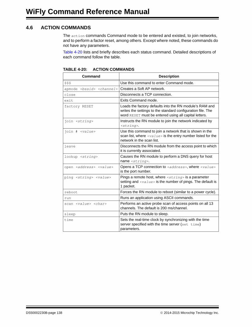
WiFly Command Reference Manual
4.6 ACTION COMMANDS
The action commands Command mode to be entered and existed, to join networks, and to perform a factor reset, among others. Except where noted, these commands do not have any parameters.
Table 4-20 lists and briefly describes each status command. Detailed descriptions of each command follow the table.
TABLE 4-20: ACTION COMMANDS
Command Description
$$$ Use this command to enter Command mode.
apmode <bssid> <channel> Creates a Soft AP network.
close Disconnects a TCP connection.
exit Exits Command mode.
factory RESET Loads the factory defaults into the RN module’s RAM and writes the settings to the standard configuration file. The word RESET must be entered using all capital letters.
join <string> Instructs the RN module to join the network indicated by <string>.
join # <value> Use this command to join a network that is shown in the scan list, where <value> is the entry number listed for the network in the scan list.
leave Disconnects the RN module from the access point to which it is currently associated.
lookup <string> Causes the RN module to perform a DNS query for host name <string>.
open <address> <value> Opens a TCP connection to <address>, where <value> is the port number.
ping <string> <value> Pings a remote host, where <string> is a parameter setting and <value> is the number of pings. The default is 1 packet.
reboot Forces the RN module to reboot (similar to a power cycle).
run Runs an application using ASCII commands.
scan <value> <char> Performs an active probe scan of access points on all 13 channels. The default is 200 ms/channel.
sleep Puts the RN module to sleep.
time Sets the real-time clock by synchronizing with the time server specified with the time server (set time) parameters.
DS50002230B-page 138 2014-2015 Microchip Technology Inc.

Command Reference
$$$
Use this command to enter Command mode. Three dollar sign characters ($$$) must be entered sequentially with no additional characters before or after each $ character. Also, do not enter a carriage return (<cr>) after typing $$$ to enter Command mode. Once the three dollar sign characters are entered, the RN module replies with CMD to indicate it is in Command mode. There is a 250 ms buffer before and after the $$$ escape sequence. If characters are sent before or after the escape sequence within this 250 ms interval, the RN module treats them as data and passes them over the TCP or UDP socket, and the RN module will not enter Command mode.
To use a different character to enter Command mode (i.e., not $$$), use with the set comm $ <char> command to assign a different character.
Example
$$$ // Enter Command mode
apmode <bssid> <channel>
This command creates a custom Soft AP network where <bssid> is the broadcast SSID and the <channel> is the channel on which the Soft AP network is created. Please note that the <bssid> and <channel> parameters are optional.
If no parameters are specified, the RN module does the following:
• Uses the string stored with the set opt device_id <string> command and appends -xy, where ‘xy’ is the last byte of the RN module’s MAC address as the SSID
• Creates the Soft AP network on channel 1
Example
apmode MyNetwork 11 // Creates a Soft AP network on channel // 11 with SSID MyNetwork
close
This command disconnects a TCP connection.
Example
close // Close the TCP connection
Note: This command does not survive power cycling. After a power cycle, the RN module behaves according to the wireless join policy determined by the set wlan join <value> command.
2014-2015 Microchip Technology Inc. DS50002230B-page 139

WiFly Command Reference Manual
exit
This command exits command mode. After leaving Command mode, the RN module responds with EXIT.
Example
exit // Leave command mode
factory RESET
This command loads the factory defaults into the RN module’s RAM and writes the settings to the standard configuration file. The word RESET must be entered using all capital letters. After typing this command, the RN module must be rebooted for the settings to take effect.
Example
factory RESET // Reset the configuration settings to the // factory defaults
join <string>
This command instructs the RN module to join the network indicated by <string>. If the network has security enabled, the passphrase must first be set using the set wlan passphrase command prior to issuing the join command.
Example
To join an unsecure network:
join roving1 // Join the network roving1
To join a secure network:
set wlan pass rubygirl // Set the password to rubygirljoin roving1 // Join the network roving1
Note: The <string> must not contain spaces. If the network SSID contains spaces, use a $ instead of the space. For example, MY$NETWORK to represent My Network.
DS50002230B-page 140 2014-2015 Microchip Technology Inc.

Command Reference
join # <value>
Use this command to join a network that is shown in the scan list, where <value> is the entry number listed for the network in the scan list. If the network is security enabled, the passphrase must first be set using the set wlan passphrase command prior to issuing the join command
Example
join # 1 // Join the network indicated by a 1 in the // scan list
leave
This command disconnects the RN module from the access point to which it is currently associated.
Example
leave // Disconnect from the access point
lookup <string>
This command causes the RN module to perform a DNS query, where <string> is the host name to search.
Example
lookup roving1 // Search for the host roving1
open <address> <value>
This command opens a TCP connection to <address>, where <value> is the port num-ber and <address> is an IP address in the form <value>.<value>.<value>.<value>, where <value> is a number between 0 and 255. If the <address> and <value> param-eters are not used, the RN module attempts to connect to the stored remote host IP address and remote port number. The <address> parameter can also be a DNS host name that the RN module attempts to resolve.
Default
Stored remote IP address and port number.
Example
open 10.20.20.62 2000 // Open a connection to 10.20.20.62 // on port 2000
2014-2015 Microchip Technology Inc. DS50002230B-page 141

WiFly Command Reference Manual
ping <string> <value> (Only available on RN131 and RN171 modules)
This command pings a remote host, where <string> is one of the parameters shown in Table 4-21 and <value> is the number of pings to send. By default, the RN module sends 1 packet. The optional <value> sends <value> pings, at 10 per second.
Default
1 packet
Example
ping 10.20.20.12 10 // Ping 10.20.20.12 10 times
ping d<domain>
This command uses Domain Name Service (DNS) to resolve the domain name during a ping.
Default
NULL
Example
ping google.com // Resolves google.com to an IP address // and pings
reboot
This command forces the RN module to reboot (similar to a power cycle).
Example
reboot // Reboot the RN module
TABLE 4-21: PING COMMAND PARAMETER OPTIONS
Option Description
g This option pings the gateway. The gateway IP address is loaded if DHCP is turned on; otherwise, it must be set using the set ip gateway <address> command.
h This option pings the stored host IP address. The host IP address can be set using the set ip host <address> command.
i This option pings a known Internet server, www.neelum.com, by first resolving the URL. This option is useful to demonstrate that DNS is working and that the device has Internet connectivity.
0 This option terminates a previously issued ping command.
<address> Ping a remote host where <address> is an IP address in the form <value>.<value>.<value>.<value>, where <value> is a number between 0 and 255.
DS50002230B-page 142 2014-2015 Microchip Technology Inc.

Command Reference
run <string>
This command is used to run an application using ASCII commands, where <string> is web_app or wps_app.
Examples
run web_app // Runs the configuration Web Server
run wps_app // Runs the WPS application
scan <value> <char>
This command performs an active probe scan of access points on all 13 channels, where <value> is an optional parameter representing the time in milliseconds per channel. The parameter <char> represents the optional parameter P, which causes the RN module to perform a passive scan, and list all access points it can see in passive mode.
When using this command, the RN module returns the MAC address, signal strength, SSID name, and security mode of the access points it finds. The default scan time is 200 ms per channel or approximately three seconds. Refer to Section 3.10.1 “Scan Output Format” for more information on the format of the scan command output.
Default
200 ms/channel
Example
scan 30 // Scan for 30 ms/channel
sleep
This command puts the RN module to sleep. The RN module can be woken by sending characters over the UART or by using the wake timer.
Example
sleep // Put the RN module to sleep
time
This command sets the real-time clock by synchronizing with the time server specified with the time server (set time) parameters. This command sends a UDP time server request packet.
Example
time // Set the real-time clock
2014-2015 Microchip Technology Inc. DS50002230B-page 143

WiFly Command Reference Manual
4.7 FILE I/O COMMANDS
The file I/O commands can be used to save, load, delete, and update configurations and other files.
Table 4-22 lists and briefly describes each status command. Detailed descriptions of each command follow the table.
del <string> <value>
This command deletes a file, where <string> is the filename and <value> is an optional number that overrides the name and uses the sector number displayed by the ls command.
Example
del my_old_config // Delete the file my_old_config
load <string>
This command reads in a new configuration file, where <string> is the file name.
Example
load my_config // Load the file my_config
ls
This command displays the files in the system.
Example
ls // Display the files in the system
TABLE 4-22: FILE I/O COMMANDS
Command Description
del <string> <value> Deletes a file.
load <string> Reads in a new configuration file.
ls Displays the files in the system.
save <string> Saves the configuration settings to a file.
boot image <value> Makes a file represented by <value> the new boot image.
ftp update <string> Deletes the back-up image file, retrieves a new image file, and updates the boot pointer to the new image.
xmodem cu <filename> Updates the boot image using the xmodem 1K protocol over UART.
DS50002230B-page 144 2014-2015 Microchip Technology Inc.

Command Reference
save <string>
This command saves the configuration settings to a file, where <string> is an optional filename. If a file name is not specified, the RN module saves the settings to a file named config (default).
Default
config
Examples
save // Saves the configuration settings to the // config file
save my_config // Saves the settings to the my_config file
boot image <value>
This command makes a file represented by <value> the new boot image.
Example
boot image 55 // Set the new boot image to a file // represented by filename 55
ftp update <string>
This command retrieves a new image file, and updates the boot pointer to the new image, where <string> is the new image file to retrieve. Refer to Section 3.14.1 “Upgrading Firmware Via FTP” for more information.
Example
ftp update wifly3-400.img // Retrieve version 4.0 firmware (RN131)
Note: After changing the boot pointer to the new image, the RN module must be rebooted to boot up with the new image. After the RN module boots up with the new image, a factory reset must be performed on the RN module to initialize all of the parameters to the factory default settings. Once reset, the parameters can be reinitialized as required.
2014-2015 Microchip Technology Inc. DS50002230B-page 145

WiFly Command Reference Manual
xmodem <option>update <string>
This command adds the capability to update the firmware over UART using the xmodem 1K protocol, where <option> is:
• u – Download firmware and set as boot image <filename> is the name of the firmware (.img or .mif file)
• c – Clean the file system option before performing a firmware update over FTP. This will delete all the files on the Flash file system (including user-defined configuration files) except the current boot image and the factory default boot image (sector number 2)
Prerequisites
• The RN module must have the following firmware version:
- RN131 and RN171 (4.40 or later)
- RN1723 (1.00 or later)
• The personal computer must have a local copy of a.img or .mif firmware file. The .img file always contains a single RN module firmware application. The .mif file may contain module firmware and other application(s) such as web_app, wps_app and/or custom files
Default
NULL
Example
xmodem cupdate wifly7-440.mif // Clean file system and upload// upload wifly7-440.mif firmware// over UART
DS50002230B-page 146 2014-2015 Microchip Technology Inc.

WiFly COMMAND
REFERENCE MANUALIndex
Aaccess point
associating........................................................ 27scan for ........................................................... 143
action commands................................................... 138alternate functions.................................................. 111alternate GPIO functions.......................................... 58analog interface pin value ...................................... 136analog interface values, show multiple .................. 136analog sensor .......................................................... 74analog-to-digital converter ....................................... 48auto-connect timer ................................................. 110auto-connect timers ................................................. 41automatic connections ............................................. 38auto-pairing, UDP .................................................... 44auto-wake timer ..................................................... 117
Bbaud rates .............................................................. 124bit ............................................................................. 24bit-mapped register
ip flags ............................................................ 100ip protocol ....................................................... 102ip tcp-mode ..................................................... 103opt format........................................................ 105show connection ............................................. 135sys trigger ....................................................... 116uart mode........................................................ 123
boot image ............................................................. 145broadcast, packet byte format.................................. 45broadcast, UDP........................................................ 44browser disconnect timer ......................................... 37
Cchannel mask......................................................... 129clock, real-time......................................................... 61close....................................................................... 139close string............................................................... 89command mode ..................................................... 139
command character setting .............................. 89exit .................................................................. 140
commandsoverview............................................................ 78reboot after ....................................................... 78set ..................................................................... 79shorthand.......................................................... 77syntax ............................................................... 77types ................................................................. 78
configuration ............................................................ 19using a configuration Web Server..................... 33
configuration Web Serverconfigure module .............................................. 33
configuration Web server ......................................... 32start in hardware ............................................... 32start in software................................................. 32
configuration web server .......................................... 31LED status ........................................................ 33set sys launch_string ...................................... 112using ................................................................. 31
connect to module in AP mode ................................ 64connection
automatic .......................................................... 38display status .................................................. 135making .............................................................. 38open .................................................................. 38timer .................................................................. 45to FTP server .................................................... 51to Web server.................................................... 47
connectionsmaking .............................................................. 27
controlling connections............................................. 40CTS pin .................................................................. 121Customer Notification Service.................................... 8Customer Support ...................................................... 8
Ddebug messages.................................................... 114debug print levels ..................................................... 59debug print message.............................................. 114debugging ................................................................ 59del .......................................................................... 144device ID setting..................................................... 106DHCP modes ........................................................... 99display
all settings ....................................................... 133analog pin value.............................................. 136broadcast settings........................................... 132communication settings .................................. 132connection status ............................................ 135firmware version.............................................. 134multiple analog interface values...................... 136network status................................................. 136optional settings .............................................. 134signal strength................................................. 137statistics .......................................................... 137system settings ............................................... 134time server settings......................................... 134
DNSdisplay settings ............................................... 133name setting ..................................................... 94name setting, back-up....................................... 94query command .............................................. 141server setting .................................................... 94using settings .................................................... 39
2014-2015 Microchip Technology Inc. DS50002230B-page 147

WiFly Command Reference Manual
documentationconventions......................................................... 6layout .................................................................. 5
Eenabling soft AP mode ............................................. 63escape buffer ($$$) .................................................. 14evaluation board
RN134............................................53, 54, 57, 120RN134, blue LED .............................................. 56RN174....................................................53, 54, 57RN174, blue LED .............................................. 56
exit.......................................................................... 140
Ffactory reset ........................................................... 140file
boot image ...................................................... 145delete .............................................................. 144ftp update ........................................................ 145load ................................................................. 144ls ..................................................................... 144save ................................................................ 145
file I/O commands .................................................. 144files
create on FTP server ........................................ 51get from FTP server .......................................... 52
firmwaredisplay version ................................................ 134
firmware upgrade ..................................................... 69flow control ....................................................... 55, 121flush size setting....................................................... 91flush timer setting ..................................................... 92FTP
client.................................................................. 51connect to ......................................................... 51create files on server......................................... 51display settings ............................................... 133filename setting................................................. 96get files form server .......................................... 52mode setting ..................................................... 96password........................................................... 97remote port number setting............................... 96server setting .................................................... 95starting directory ............................................... 95timeout setting................................................... 97update ............................................................. 145upgrading firmware ........................................... 67username setting .............................................. 97
Gget
broadcast ........................................................ 132com ................................................................. 132dns .................................................................. 133everything ....................................................... 133ftp .................................................................... 133ip ..................................................................... 133mac ................................................................. 133option .............................................................. 134sys................................................................... 134
time ................................................................. 134uart .................................................................. 134wlan................................................................. 134
get commands........................................................ 132GPIO
alternate functions..................................... 56, 111controlling connections with .............................. 40default power-up value setting ........................ 117disable LEDs ..................................................... 56output setting................................................... 115pin bitmask ................................................ 57, 113pin usage................................................... 57, 113set as inputs or outputs instantly..................... 114setting alternate functions ................................. 58setting direction ................................................. 56show pin level status ....................................... 136soft AP mode alternative functions.................... 66
GPIO10 .................................................................. 124GPIO4 .................................................................... 117GPIO5 .............................................................. 39, 117GPIO6 .............................................................. 39, 117GPIO8 .................................................................... 116GPIO9
invoking configuration Web server .................... 32
Hhardware
start configuration Web server .......................... 32hardware flow control ............................................... 55heartbeat, UART ...................................................... 60hello string ................................................................ 90home network........................................................... 28HTML
built-in modes.................................................... 46client example ............................................. 49, 50connect to server............................................... 47post binary data................................................. 48post sensor data................................................ 48retrieve data ...................................................... 46using client ........................................................ 46
HTTP Client/Web server setting............................. 105
II/O alternate functions ............................................ 111I/O port direction setting ......................................... 113idle timer............................................................. 37, 41inputs, sensor ........................................................... 74IP
address setting.................................................. 98address setting, back-up ................................... 98DHCP setting .................................................... 99display settings................................................ 133gateway setting ............................................... 100host setting...................................................... 101local port setting .............................................. 101netmask setting ............................................... 101protocol setting................................................ 102remote port setting .......................................... 102TCP settings.................................................... 103TCP/IP functions ............................................. 100using back-up.................................................... 39
DS50002230B-page 148 2014-2015 Microchip Technology Inc.

Index
Jjoin ......................................................................... 140join # ...................................................................... 141join timer ................................................................ 104
Llast device connected in AP mode........................... 65launch
web application ............................................... 112WPS application ........................................30, 112
leave ...................................................................... 141LEDs
configuration web server................................... 33disable .............................................................. 56
link monitor............................................................. 128load ........................................................................ 144load configuration file ............................................. 144lookup .................................................................... 141ls ............................................................................ 144
MMAC, display settings ............................................ 133making connections ............................................27, 38match character setting............................................ 91module
accepting data .................................................. 53connect to remote host ..................................... 42disconnect from AP......................................... 141factory reset .................................................... 140reboot.............................................................. 142sleep ................................................................. 53wake ................................................................. 53
Module Configuration tab......................................... 37
NNetwork Configuration tab ....................................... 35network status, show ............................................. 136network, join........................................................... 140network, joining ........................................................ 27
Oopen ....................................................................... 141open connection....................................................... 38open string ............................................................... 90optional settings, display........................................ 134
Ppackets, time stamping ............................................ 62parity ...............................................................121, 124passphrase ............................................................ 129passphrase, show or hide ...................................... 127ping ........................................................................ 142pin-level status, show............................................. 136power, sensor .......................................................... 75power-up, GPIO default setting.............................. 117print functions........................................................... 59print messages, setting .......................................... 114
Rraw baud rates ....................................................... 124real-time clock.....................................................41, 61real-time clock setting ............................................ 143
reboot ..................................................................... 142Recommended Reading ............................................ 7replacement character ........................................... 105RN modules
comparing ......................................................... 11features ............................................................. 12
RN131 module ................................................. 11, 126antenna ............................................................. 12data sheet ........................................................... 7default FTP parameter ...................................... 22default GPIO state ............................................ 57default mask...................................................... 56default system parameter ................................. 23default wlan parameter ..................................... 24evaluation kit user’s guide................................... 7GPIO pins ......................................................... 12SSID............................................................ 32, 63ultra-low power.................................................. 12
RN171 module ................................................. 11, 126antenna ............................................................. 12data sheet ........................................................... 7default FTP parameter ...................................... 22default GPIO state ............................................ 57default mask...................................................... 56default system parameter ................................. 23evaluation kit user’s guide................................... 7GPIO pins ......................................................... 12SSID............................................................ 32, 63ultra-low power.................................................. 12
RN1723 module ............................................... 11, 126antenna ............................................................. 12data sheet ........................................................... 7default FTP parameter ...................................... 22default GPIO state ............................................ 57default mask...................................................... 56default system parameter ................................. 23evaluation kit user’s guide................................... 7GPIO pins ......................................................... 12SSID............................................................ 32, 63
RSSIset sample number ......................................... 106set threshold ................................................... 107
RSSI, show ............................................................ 137RTC.............................................................41, 61, 119RTS/CTS.................................................................. 55
Ssample sensor pins .................................................. 74save........................................................................ 145scan........................................................................ 143security modes ....................................................... 125sensor ...................................................................... 74
input trigger values.......................................... 116pin voltage settings ......................................... 109post data to web................................................ 48post data to web example ................................. 49power ........................................................ 75, 109sample pins....................................................... 74setting pins to sample ..................................... 108wake on input.................................................... 54
set
2014-2015 Microchip Technology Inc. DS50002230B-page 149

WiFly Command Reference Manual
broadcast address ............................................ 85broadcast backup.............................................. 87broadcast interval.............................................. 88broadcast port ................................................... 88broadcast remote .............................................. 88comm $ ............................................................. 89comm close....................................................... 89comm idle.......................................................... 90comm match ..................................................... 91comm open ....................................................... 90comm remote .................................................... 90comm size......................................................... 91comm time ........................................................ 92dns address ...................................................... 94dns backup........................................................ 94dns name .......................................................... 94ftp addr .............................................................. 95ftp dir ................................................................. 95ftp filename ....................................................... 96ftp mode ............................................................ 96ftp pass ............................................................. 97ftp remote.......................................................... 96ftp time .............................................................. 97ftp user .............................................................. 97ip address ......................................................... 98ip backup........................................................... 98ip dhcp .............................................................. 99ip flags............................................................. 100ip gateway....................................................... 100ip host ............................................................. 101ip localport....................................................... 101ip netmask....................................................... 101ip protocol ....................................................... 102ip remote ......................................................... 102ip tcp-mode ..................................................... 103opt average ..................................................... 106opt deviceid ..................................................... 106opt format ........................................................ 105opt jointmr ....................................................... 104opt password................................................... 106opt replace ...................................................... 105opt signal......................................................... 107q power ........................................................... 109q sensor .......................................................... 108sys autoconn................................................... 110sys autosleep .................................................. 111sys iofunc ........................................................ 111sys launch_string ............................................ 112sys mask ......................................................... 113sys output........................................................ 115sys printlvl ....................................................... 114sys sleep ......................................................... 115sys trigger ....................................................... 116sys value ......................................................... 117sys wake ......................................................... 117time address ................................................... 118time enable ..................................................... 118time port .......................................................... 118time raw .......................................................... 119uart baud......................................................... 120
uart flow........................................................... 121uart instant ...................................................... 122uart mode ........................................................ 123uart raw ........................................................... 124uart tx .............................................................. 124wlan auth......................................................... 125wlan channel ................................................... 126wlan ext_antenna ............................................ 126wlan hide ......................................................... 127wlan join .......................................................... 127wlan key .......................................................... 128wlan linkmon ................................................... 128wlan mask ....................................................... 129wlan phrase..................................................... 129wlan rate.......................................................... 130wlan ssid ......................................................... 130wlan tx ............................................................. 131
set commands .......................................................... 79settings, debug print message ............................... 114shorthand ................................................................. 77show
connection....................................................... 135io ..................................................................... 136net ................................................................... 136q ...................................................................... 136q 0x1 ............................................................... 136rssi................................................................... 137stats................................................................. 137time ................................................................. 137
show signal strength............................................... 137signal strength, show.............................................. 137sleep................................................................. 53, 143
UDP................................................................... 45sleep timer........................................................ 41, 115SNTP................................................................ 61, 118soft AP mode............................................................ 63
apmode command .......................................... 139beacon .............................................................. 84connect to module............................................. 64default settings .................................................. 63display settings................................................ 132enable in hardware............................................ 63enable in software ............................................. 64enabling............................................................. 63GPIO alternative functions ................................ 66last device connected........................................ 65link monitor........................................................ 66link_monitor....................................................... 85passphrase........................................................ 85probe ................................................................. 84reboot ................................................................ 85route data between clients ................................ 66view associated devices.................................... 65
softwarestart configuration Web server .......................... 32
SSIDreplacement character .................................... 105setting.............................................................. 130
statistics, show ....................................................... 137status commands ................................................... 135
DS50002230B-page 150 2014-2015 Microchip Technology Inc.

Index
supported access points .......................................... 12system settings, display ......................................... 134system timers ........................................................... 41
TTCP
close connection ........................................43, 139connection password ...................................... 106connection timer ............................................... 42open connection ............................................... 42open connection command............................. 141
Terminal tab ............................................................. 36time ........................................................................ 143time server, display settings................................... 134time since mode was last powered or booted........ 137time stamping........................................................... 62timer
auto-connect ................................................... 110auto-wake ....................................................... 117browser disconnect ........................................... 37configuration web server................................... 37connection ........................................................ 45idle .................................................................... 37sleep ............................................................... 115TCP connection ................................................ 42transitions ......................................................... 41
timer server port setting ......................................... 118timers ....................................................................... 41trigger, wakeup setting........................................... 116
UUART
baud setting .................................................... 120connect to web server....................................... 47display settings ............................................... 134flow control.................................................55, 121GPIO10........................................................... 124heartbeat messages ......................................... 60instant baud change setting............................ 122mode setting ................................................... 123posting data to web example ............................ 50raw setting ...................................................... 124TX pin setting.................................................. 124wake on activity ................................................ 54
UDPauto-pairing....................................................... 44broadcast .......................................................... 44retry................................................................... 44sending data ..................................................... 43
sleep ................................................................. 45UDP heartbeat ................................................... 87, 88
port setting ........................................................ 88secondary address............................................ 87
using configuration web server ................................ 31using GPIO9............................................................. 32
Vver .......................................................................... 134view associated devices, soft AP mode ................... 65voltage, sensor pins ............................................... 109
Wwake......................................................................... 53wake timer................................................................ 41wake, on sensor input .............................................. 54wake, on UART activity ............................................ 54web application
launch ............................................................. 112web server
connect automatically ....................................... 47post binary ........................................................ 48retrieve data ...................................................... 46
web server, configuration ......................................... 31WEP key ................................................................ 128WEP-128................................................................ 125Wi-Fi protected setup ............................................... 28Wi-Fi, transmit power setting.................................. 131wireless data rate, setting ...................................... 130WLAN
authentication setting ...................................... 125channel mask setting ...................................... 129channel setting................................................ 126display settings ............................................... 134external antenna setting.................................. 126hide WEP key setting...................................... 127join setting....................................................... 127link monitor setting .......................................... 128passkey setting ............................................... 128passphrase setting.......................................... 129SSID setting .................................................... 130Wi-Fi transmit power setting ........................... 131wireless data rate setting ................................ 130
WPA1 ..................................................................... 125WPA2-PSK............................................................. 125WPE-64.................................................................. 125WPS ......................................................................... 28
launch application ..................................... 30, 112
2014-2015 Microchip Technology Inc. DS50002230B-page 151

WiFly Command Reference Manual
NOTES:
DS50002230B-page 152 2014-2015 Microchip Technology Inc.

2014-2015 Microchip Technology Inc. DS50002230B-page 153
NOTES:

DS50002230B-page 154 2014-2015 Microchip Technology Inc.
AMERICASCorporate Office2355 West Chandler Blvd.Chandler, AZ 85224-6199Tel: 480-792-7200 Fax: 480-792-7277Technical Support: http://www.microchip.com/supportWeb Address: www.microchip.com
AtlantaDuluth, GA Tel: 678-957-9614 Fax: 678-957-1455
Austin, TXTel: 512-257-3370
BostonWestborough, MA Tel: 774-760-0087 Fax: 774-760-0088
ChicagoItasca, IL Tel: 630-285-0071 Fax: 630-285-0075
ClevelandIndependence, OH Tel: 216-447-0464 Fax: 216-447-0643
DallasAddison, TX Tel: 972-818-7423 Fax: 972-818-2924
DetroitNovi, MI Tel: 248-848-4000
Houston, TX Tel: 281-894-5983
IndianapolisNoblesville, IN Tel: 317-773-8323Fax: 317-773-5453
Los AngelesMission Viejo, CA Tel: 949-462-9523 Fax: 949-462-9608
New York, NY Tel: 631-435-6000
San Jose, CA Tel: 408-735-9110
Canada - TorontoTel: 905-673-0699 Fax: 905-673-6509
ASIA/PACIFICAsia Pacific OfficeSuites 3707-14, 37th FloorTower 6, The GatewayHarbour City, Kowloon
Hong KongTel: 852-2943-5100Fax: 852-2401-3431
Australia - SydneyTel: 61-2-9868-6733Fax: 61-2-9868-6755
China - BeijingTel: 86-10-8569-7000 Fax: 86-10-8528-2104
China - ChengduTel: 86-28-8665-5511Fax: 86-28-8665-7889
China - ChongqingTel: 86-23-8980-9588Fax: 86-23-8980-9500
China - DongguanTel: 86-769-8702-9880
China - HangzhouTel: 86-571-8792-8115 Fax: 86-571-8792-8116
China - Hong Kong SARTel: 852-2943-5100 Fax: 852-2401-3431
China - NanjingTel: 86-25-8473-2460Fax: 86-25-8473-2470
China - QingdaoTel: 86-532-8502-7355Fax: 86-532-8502-7205
China - ShanghaiTel: 86-21-5407-5533 Fax: 86-21-5407-5066
China - ShenyangTel: 86-24-2334-2829Fax: 86-24-2334-2393
China - ShenzhenTel: 86-755-8864-2200 Fax: 86-755-8203-1760
China - WuhanTel: 86-27-5980-5300Fax: 86-27-5980-5118
China - XianTel: 86-29-8833-7252Fax: 86-29-8833-7256
ASIA/PACIFICChina - XiamenTel: 86-592-2388138 Fax: 86-592-2388130
China - ZhuhaiTel: 86-756-3210040 Fax: 86-756-3210049
India - BangaloreTel: 91-80-3090-4444 Fax: 91-80-3090-4123
India - New DelhiTel: 91-11-4160-8631Fax: 91-11-4160-8632
India - PuneTel: 91-20-3019-1500
Japan - OsakaTel: 81-6-6152-7160 Fax: 81-6-6152-9310
Japan - TokyoTel: 81-3-6880- 3770 Fax: 81-3-6880-3771
Korea - DaeguTel: 82-53-744-4301Fax: 82-53-744-4302
Korea - SeoulTel: 82-2-554-7200Fax: 82-2-558-5932 or 82-2-558-5934
Malaysia - Kuala LumpurTel: 60-3-6201-9857Fax: 60-3-6201-9859
Malaysia - PenangTel: 60-4-227-8870Fax: 60-4-227-4068
Philippines - ManilaTel: 63-2-634-9065Fax: 63-2-634-9069
SingaporeTel: 65-6334-8870Fax: 65-6334-8850
Taiwan - Hsin ChuTel: 886-3-5778-366Fax: 886-3-5770-955
Taiwan - KaohsiungTel: 886-7-213-7828
Taiwan - TaipeiTel: 886-2-2508-8600 Fax: 886-2-2508-0102
Thailand - BangkokTel: 66-2-694-1351Fax: 66-2-694-1350
EUROPEAustria - WelsTel: 43-7242-2244-39Fax: 43-7242-2244-393
Denmark - CopenhagenTel: 45-4450-2828 Fax: 45-4485-2829
France - ParisTel: 33-1-69-53-63-20 Fax: 33-1-69-30-90-79
Germany - DusseldorfTel: 49-2129-3766400
Germany - KarlsruheTel: 49-721-625370
Germany - MunichTel: 49-89-627-144-0 Fax: 49-89-627-144-44
Italy - Milan Tel: 39-0331-742611 Fax: 39-0331-466781
Italy - VeniceTel: 39-049-7625286
Netherlands - DrunenTel: 31-416-690399 Fax: 31-416-690340
Poland - WarsawTel: 48-22-3325737
Spain - MadridTel: 34-91-708-08-90Fax: 34-91-708-08-91
Sweden - StockholmTel: 46-8-5090-4654
UK - WokinghamTel: 44-118-921-5800Fax: 44-118-921-5820
Worldwide Sales and Service
07/14/15