winbox 350winbox-350 descriptive specifications 1. general characteristics the winbox cassette...
TRANSCRIPT
Page - Copyright Llaza, S.A. - May 2012
WINBOX-350
Technical Manual
WINBOX-350

Page 2 - Copyright Llaza, S.A. - May 2012
WINBOX-350

Page 3 - Copyright Llaza, S.A. - May 2012
WINBOX-350
Contents
Descriptive specifications 4-7
Cutting, selection, and classification tables 8
Annotated cross-sectional diagrams 9-10
Assembly instructions 11-15
Installation instructions 16-17
Examples of installations 18-19

Page 4 - Copyright Llaza, S.A. - May 2012
WINBOX-350

Page 5 - Copyright Llaza, S.A. - May 2012
WINBOX-350
Descriptive specifications
1. GENERAL CHARACTERISTICS
The WINBOX cassette awning features an advanced design and cutting-edge technology to cover large
dimensions with only two arms. Its rounded lines also mean that it goes well with surroundings of any type.
The tension transmission components required for the operation of the WINBOX awning are concealed
from view inside the articulated extendible arms, giving the system a clean, compact look and making it a
very modern awning that fits perfectly with the latest architectural styles.
2– DESCRIPTION OF THE SYSTEM
The advanced technology applied to the LLAZA-WIN system provides a series of advantages which guar-
antee that the awning performs at peak efficiency:
■ Improved durability of the fabric and the system as a whole
■ Enhanced strength in the arm sections
■ Ease of installation: the BOX system significantly reduces on-site installation time
The patented LLAZA-WIN system deserves special mention. It involves a double tensioning system, which
is able to apply stronger and more uniform forces along the entire range of the arm's opening. The results
of this are seen in the fabric, which is held more uniformly taut during the entire process. The arm joint fea-
tures a double bearing, which means that the rotating components are subjected to less wear and that the
system generates less noise due to friction. The WIN arm is the only one on the market with this set of pa-
tented characteristics.
As with any sun protection system, this product also seeks to achieve the greatest suitability in terms of two
intrinsic necessities:
■ Dimensions
■ Exposure to the elements (sun, wind, rain)
To address these factors, the materials chosen in the manufacture of this product have taken on vital importance.
3. DESCRIPTION OF THE PARTS THAT MAKE UP THE WINBOX-300
This system offers advanced adjustment thanks to the bracket’s rack-based
system designed by LLAZA. The system can inclined quickly, easily and very
accurately.
An allen-head bolt allows the desired degree of inclination to be set from the
bottom of the cassette.

Page 6 - Copyright Llaza, S.A. - May 2012
WINBOX-350
Descriptive specifications
4. THE LLAZA-WIN SYSTEM ARMS
The articulation of the WIN arm keeps the tension transmission system
entirely hidden from view, giving it a highly innovative and elegant appear-
ance. Two stainless steel bearings are also used to provide improved du-
rability and to eliminate noise during operation.
The LLAZA-WIN System's arms consist of profiles, an internal double ten-
sioning system (elongation and compression), and a system for transmis-
sion of the longitudinal difference by means of a patented flexible tape system. This ensures that the prod-
uct performs well above the applicable European EN 13561 standard.
Given the dimensions and forces associated with this type of articulation, the rotational motion of the rolling
tube during extension-retraction of the fabric is always provided by an electric motor, which is located inside
one end of the rolling tube.
The other end of the rolling tube turns on a stainless steel ball-bearing system that ensures technically cal-
culated support so the system operates smoothly and perfectly every time.
The forward profile that serves as a guiding element for opening and closing of the system has been de-
signed with carefully calculated dimensions, in order to allow its use with extended widths, and also to fur-
ther lend an ideal aesthetic appearance to the system. This profile has a concave interior area that incorpo-
rates as series of polyamide strips, which cushion the parts of the arms that make contact. It also features a
pivot system to ensure a perfect fit when the front profile joins with the cassette profile.
The side covers that enclose the inclination system are made of injected aluminium, and give the cassette
strength, rigidity, and a high-quality finish. An interior tightening bolt ensures firm attachment of these co-
vers.
To make installation more practical and to save time, the attachment components have been simplified, and
final assembly can now be performed using only two spanners for the entire process.
The cassette assembly is anchored to the lower part of the bracket plates, in order to facilitate access to
them. These bracket plates remain partly uncovered by the side covers, which allows the inclination of the
system to be adjusted even after the entire assembly process has been completed.
The maximum dimensions for an installation with this model is 6 metres of width by 3.5 metres of projec-
tion.
Its inclination can be adjusted from 6° to 60°.
5. FINAL CONSIDERATIONS
■ Our manufacturing processes and the corresponding management controls have allowed us to be grant-
ed the ISO-9001:2008 certification for design and manufacturing.
■ Our compliance with the requirements of the European EN 13561 standard allows us to issue the State-
ment of Conformity for the CE marking.
■ Application of the conditions required by EAA/Qualicoat standards allow us to offer a 3-year guarantee on
lacquer finishes.

Page 7 - Copyright Llaza, S.A. - May 2012
WINBOX-350
Descriptive specifications
6. COMPONENT SPECIFICATIONS
GEOMETRIC PROPERTIES
Geometry Section (mm2) Mt (cm4)
Structure
Wall support (1000 mm) - 1804,281 Ixx = 484.085 Iyy = 7.201
Cassette profile - 1262,306 Ixx = 175.07 Iyy = 314.291
Weather cover profile - 808,567 Ixx = 21.34 Iyy = 191.78
Front drop bar profile - 1029,784 Ixx = 260.635 Iyy = 82.62
WIN-350 model arms
Structural components - -
Front aluminium profile - 335 Ixx= 4.24 Iyy = 16.21
Rear aluminium profile - 514 Ixx = 9.86 Iyy = 27.04
TECHNICAL CHARACTERISTICS
Structure Process Desig. Material A* B* C* D*
Components Gravity moulding Aluminium 170 80 5 55
Wall support Extrusion Aluminium 270 225 6 -
Ceiling bracket Sand moulding Aluminium 80 140 2 55
Cassette profile Extrusion Aluminium 175 130 6 -
Weather cover profile Extrusion Aluminium 175 130 6 -
Front drop bar profile Extrusion Aluminium 175 130 6 -
Extrusion comp. Extrusion Aluminium
WIN-350 model arms
Components Pressure moulding Aluminium 180 90 2,5 55
Front alum. Aluminium Extrusion Aluminium 175 130 6 -
Rear alum. Aluminium Extrusion Aluminium 270 225 6 -
DESCRIPTION
A* Resistance to traction Rm (Mpa)
B* Elastic limit Rp 0,2 (Mpa)
C* Elongation A50 mm (%)
D* Brinell Hardness HBS
MAXIMUM DIMENSIONS MAXIMUM WIDTH MAXIMUM PROJECTION
600 350
ANGLE OF INCLINATION WALL CEILING
6° to 60° 6° to 60°

Page 8 - Copyright Llaza, S.A. - May 2012
WINBOX-350
Cutting, selection, and classification tables
Distance between joints 4 cm
CUTTING OF PROFILES AND FABRIC (in mm)
SOMFY MOTOR
UPPER CASSETTE PROFILE W-153
CASSETTE HOUSING W-155
FRONT DROP BAR PROFILE W-165
80 mm ROLLING TUBE W-123
PROTECTOR PROFILE W-157
FABRIC W-190
WINBOX-350 WIND CLASSIFICATION
WIDTH 200 250 300 350 400 450 500 550 600
PROJECTION
150 3 3 3 3 3 3 3 3 3
200 3 3 3 3 3 3 3
250 3 3 3 3 3 3
300 3 3 3 2 2
350 2 2 2 2
MOTOR SELECTION TABLE (in Nw/m)
PROJECTION 150 200 250 300 350
ROLLING TUBE Ø 80 70 Nw/m 85 Nw/m
EN 13561 STANDARD – WIND CLASSIFICATION TABLE
CLASS RANGE (Km/h) BEAUFORT
CLASS 0 0 to 19 1-3 Beaufort Leaves and small twigs constantly moving.
CLASS 1 20 to 28 4 Beaufort Dust and loose paper raised. Small branches begin to move.
CLASS 2 29 to 38 5 Beaufort Branches of a moderate size move. Small trees in leaf begin to
sway.
CLASS 3 39 to 49 6 Beaufort Large branches in motion. Umbrella use becomes difficult.
MINIMUM WIDTH
No. of ARMS ARM PROJECTION
2 150 200 250 300 350
195 245 295 345 395

Page 9 - Copyright Llaza, S.A. - May 2012
WINBOX-350
Annotated cross-sectional diagrams
FACE MOUNTING
CROSS-SECTIONAL DIMENSIONS

Page 10 - Copyright Llaza, S.A. - May 2012
WINBOX-350
Annotated cross-sectional diagrams
CEILING MOUNTING
CROSS-SECTIONAL DIMENSIONS

Page 11 - Copyright Llaza, S.A. - May 2012
WINBOX-350
Assembly instructions
1. ASSEMBLY OF THE CASSETTE
A
Insert the fabric protector profile (A) into the lodg-ing points in the cassette for this purpose. This prevents the fabric from rubbing against the alu-minium when being extended or retracted.
The rack system and the arm fork attach-
ment point are on the inside of the brack-
et. Attach one of these interior parts to
one side to the cassette profile using the
DIN 7982, 4.2x45 screws (C).
Once one side has been screwed on,
place the rolling tube inside the cassette
profile, with the fabric already rolled onto
it (D). Next, attach the interior part of the
side bracket to the other side as done
with the first one, using the three DIN
7982, 4.2x45 screws.
D
B
Separate the two parts of the side brackets by remov-
ing the DIN 912 allen-head bolts (B) .
C

Page 12 - Copyright Llaza, S.A. - May 2012
WINBOX-350
Assembly instructions
Now install the front fabric profile,
fitting it onto the cassette profile
and attaching it to the sides using
the DIN 7982, 4.2x45 screws (E).
Pieces of adhesive draft excluder
strip can be attached to the front
interior of this profile to prevent
noise when the cassette closes. E
F
IMPORTANT
Prior to re-joining the two elements of the bracket, insert the DIN 933, M6x35 bolts (F) with the
heads on the inside, and use the plastic washers to hold them in position while the two components
are assembled.
Now re-attach the outside of the
side bracket, using the bolts that
were previously removed.
To couple these two components
properly, the teeth of the racks on
both sides must be at the same lev-
el, according to the inclination of the
awning, which can later be adjusted
after final installation.

Page 13 - Copyright Llaza, S.A. - May 2012
WINBOX-350
Assembly instructions
2. INSTALLING THE END BRACKET AND MOTOR BRACKET
Once the bearing end of the rolling tube is inserted, position the bracket plate along with the bear-
ing (G), and attach it using the bolts previously inserted and the self-locking M6 nuts (H).
G
J
K
H
Attach the HiPro bracket (I) to
the bracket plate using the DIN
7991, M6x12 bolts (J) (kit refer-
ence 11002035050).
Remember to attach the motor
to the bracket using the clip (K).
Next, insert the motor assembly
with the drive wheel and the
adaptor crown into the inside of
the rolling tube, then attach the
bracket plate using the bolts
previously inserted and the oth-
er three self-locking nuts (H).
IMPORTANT
In order to ensure perfect clo-
sure of the WINBOX system,
the motor power selection cal-
culations must be respected.
H
I

Page 14 - Copyright Llaza, S.A. - May 2012
WINBOX-350
Assembly instructions
3. INSTALLING THE ARMS
L
O
M
Remove the arm bracket pins and place them on
the corresponding side.
Now re-insert the pins, inserting the M6x12 tight-
ening stud (L), but do not tighten it all the way.
Use the groove in the lower part of the pin to turn
it, until the other M6x25 stud (M) can be inserted
to the point at which it gives slight resistance.
4. INSTALLING THE ARM END PIECES
Insert the end pieces into the end of the arm, attaching them
using the DIN 7991, M10x60 bolt (N). Also position the plate
(O) for attachment to the drop bar profile.
The position of each end piece must correspond with the letter
marked on it.
(L = left, R = right) N
By tightening or loosening this stud (M) and opening
and closing the arm manually, the level of the arm
joints can be adjusted so that they are exactly equal,
preferable slightly inclined towards the top. Once the-
se positions are adjusted, firmly tighten the upper stud
(L).
PIN

Page 15 - Copyright Llaza, S.A. - May 2012
WINBOX-350
Assembly instructions
5. INSTALLING THE FRONT PROFILE
Slide the front drop bar profile
onto the fabric, by inserting the
hem rod into the slot in the pro-
file.
Secure the fabric into the profile
using the spreader and screw
on each end.
From the side, slide the plates
(O) attached to the arm end
pieces into the drop bar profile.
O
P After inserting the Mikalor thread-
ed plates (P) into their slots, at-
tach the aluminium side caps to
the front drop bar profile.
Before doing this, remember to
insert the polyamide strips (Q)
into the profile interior.
There are two of these strips for
each side, so that one will match
up with each of the arm forks and
arm joints. Q
Page 16 - Copyright Llaza, S.A. - May 2012
WINBOX-350
Installation of the awning
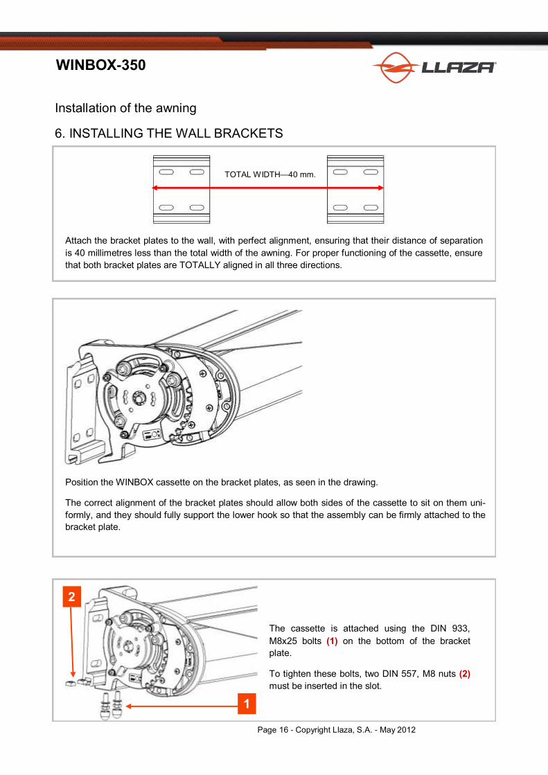
6. INSTALLING THE WALL BRACKETS
R
Attach the bracket plates to the wall, with perfect alignment, ensuring that their distance of separation
is 40 millimetres less than the total width of the awning. For proper functioning of the cassette, ensure
that both bracket plates are TOTALLY aligned in all three directions.
Position the WINBOX cassette on the bracket plates, as seen in the drawing.
The correct alignment of the bracket plates should allow both sides of the cassette to sit on them uni-
formly, and they should fully support the lower hook so that the assembly can be firmly attached to the
bracket plate.
2
1
The cassette is attached using the DIN 933,
M8x25 bolts (1) on the bottom of the bracket
plate.
To tighten these bolts, two DIN 557, M8 nuts (2)
must be inserted in the slot.
TOTAL WIDTH—40 mm.

Page 17 - Copyright Llaza, S.A. - May 2012
WINBOX-350
Installation of the awning
7. FINAL ADJUSTMENT OF THE INCLINATION
3
B
4
By using the allen key (3) inserted into the rack
bolt, the height of each arm can be adjusted in
order to obtain the desired and accurate level.
To work correctly, the bolts (B) must first be
slightly loosened. It is essential that these are re-
tightened once the adjustment process is com-
pleted.
As a final step in the installation, use pressure to
attach the side covers for the cassette (4).
For the exit point for the motor's power cord, drill
through the cover, always from the bottom, and
insert the rubber insulating cable grommet.
IMPORTANT
To prevent accidental detachment of the side caps,
an attachment screw is included (5), which screws
into a threaded tower (6) in the cap.
This screw is made of polyamide, so that if the mo-
tor malfunctions with the cassette closed, the cap
can be pried off to provide access to the motor for
replacement.
6
5

Page 18 - Copyright Llaza, S.A. - May 2012
WINBOX-350
Photos
8. EXAMPLES OF INSTALLATIONS

Page 19 - Copyright Llaza, S.A. - May 2012
WINBOX-350
Photos
NOTE: LLAZA S.A. owns the copyrights to the photographs, illustrations, and text in this publication, and these may
not be used, copied, or reproduced in any form, nor by any means, without prior permission from LLAZA, S.A. The
company reserves the right to take legal action in cases of unauthorised usage.

Page 20 - Copyright Llaza, S.A. - May 2012
WINBOX-350
LLAZA WORLD, S.A. - Tramuntana, 1- Polígono Ind. Roques Roges IV (P.O. Box 11) - 43460 - ALCOVER
Tel. +34 977 990 600 - Fax +34 977 990 610 [email protected] - [email protected] www.llaza.com