winch launch manual
TRANSCRIPT

THE GLIDING FEDERATION OF AUSTRALIA
WINCH LAUNCHING MANUAL INCORPORATING AUTO-TOWING
GFA Winch Launching Manual Issue 1, 1998

GFA Winch Launching Manual Issue 1, 1998
WINCH LAUNCHING MANUAL
Issue 1, 1998
Published by:
The Gliding Federation of Australia Building 130, Wirraway Road,
Essendon Airport, Victoria 3014, Australia
ABN 99 008 560 263
Phone: (03) 0379 7411
Fax: (03) 9379 5519 Email: [email protected]
© Copyright – Gliding Federation of Australia, 2007

i
Table of Contents 1. INTRODUCTION ................................................................................................. 1 2. BASIC WINCH LAUNCH PRINCIPLES .............................................................. 1
2.1 The stages of a winch launch ....................................................................... 1 3. GLIDER CONSIDERATIONS ............................................................................. 3
3.1 Hook positions and launching characteristics .............................................. 3 3.1.1. The “shoulder” release hook .................................................................... 3 3.1.2. The “belly” release hook ........................................................................... 4 3.1.3. Unwanted pitching moments .................................................................... 4 3.1.4. “Porpoising” on the launch ....................................................................... 5 3.1.5. Other unwanted moments ........................................................................ 6 3.1.6. Automatic back-release ............................................................................ 6 3.1.7. Predicting likely launch characteristics ..................................................... 7 3.1.8. Useful tips ................................................................................................ 7 3.1.9. Final reminders ..................................................................................... 8
3.2. Winch-launching loads and launch-speed boundaries ................................. 8 3.2.1. Winch-launching loads .......................................................................... 8 3.2.2. Wing bending relief ............................................................................... 9 3.2.3. The relevance of bending relief to winch-launching .............................. 9 3.2.4. The purpose of the weak-link .............................................................. 10 3.2.5. Launch-speed boundaries .................................................................. 11
4. PILOT CONSIDERATIONS .............................................................................. 13 4.1. Correct launch technique ........................................................................... 13
4.1.1. Ground-run and separation ................................................................. 13 4.1.2. Initial climb .......................................................................................... 14 4.1.3. The maximum speed placard and the initial climb .............................. 15 4.1.4. Full climb ............................................................................................. 16 4.1.5. The maximum speed placard and the full climb .................................. 17 4.1.6. The effect of the weight of the wire ..................................................... 17 4.1.7. The release ......................................................................................... 17 4.1.8. Winch-launching in crosswinds ........................................................... 17 4.1.9. Launch speed signals ......................................................................... 18 4.1.10. Kiting ................................................................................................... 18
4.2. Incorrect launch techniques ....................................................................... 18 4.2.1. Holding the glider down ...................................................................... 18 4.2.2. Allowing the glider to “self-rotate” ....................................................... 19 4.2.3. The “Kavalierstart” .............................................................................. 20
4.3. Launch failures - Philosophical and training considerations ....................... 20 4.3.1. Introduction ......................................................................................... 20 4.3.2. The mental approach to launch failures .............................................. 20
4.4. The physical characteristics of launch-failures ........................................... 22 4.4.1. Cable breaks ....................................................................................... 22 4.4.2. Land ahead or circuit? ........................................................................ 25 4.4.3 Inertial factors ..................................................................................... 26 4.4.4. Preference for landing ahead .............................................................. 27 4.4.5. Briefing versus training ....................................................................... 27 4.4.6. The non-manoeuvring area ................................................................. 27 4.4.7. Engine failures .................................................................................... 28
5. WINCH DESIGN CONSIDERATIONS .............................................................. 28
GFA Winch Launching Manual Issue 1, 1998

ii
5.1 General ...................................................................................................... 28 5.2. How much power? ..................................................................................... 29
5.2.1. Low-powered winches ........................................................................ 29 5.2.2. High-powered winches........................................................................ 29
5.3. Car retrieve or self-lay? .............................................................................. 30 5.4. Protection of personnel .............................................................................. 31
6. AIRFIELD REQUIREMENTS FOR WINCH-LAUNCHING ................................ 32 6.1 Strip length ................................................................................................. 32 6.2 Strip surroundings ...................................................................................... 32 6.3. Strip layout and cable safety ...................................................................... 33 6.4. Diagram - Recommended strip layout and safety precautions ................. 34
7. CABLES AND ANCILLARY EQUIPMENT ........................................................ 34 7.1. Cable types ................................................................................................ 34
7.1.1. Solid wire ............................................................................................ 34 7.1.2. Stranded cable (wire rope) .................................................................. 36 7.1.3. Polypropylene rope ............................................................................. 36
7.2. The cable end ............................................................................................ 37 7.2.1. Trace ................................................................................................... 37 7.2.2. Drogue parachute ............................................................................... 38 7.2.3. Weak link ............................................................................................ 38 7.2.4. Types of weak-link .............................................................................. 39 7.2.5. Rings ................................................................................................... 41
8. SIGNALLING SYSTEMS .................................................................................. 42 8.1. Visual signalling systems ........................................................................... 43
8.1.1. Lamp signals ....................................................................................... 43 8.1.2. Bat signals .......................................................................................... 43 8.1.3. Wing-waggling .................................................................................... 44
8.2. Aural signalling systems ............................................................................ 44 8.2.1. Field telephone ................................................................................... 44 8.2.2. Radio .................................................................................................. 45 8.2.3. Particular requirement when using radio for launch signals ................ 45 8.2.4. Special precaution for operators of all winch-launch signalling systems 45
9. WINCH-DRIVER TRAINING ............................................................................. 46 9.1. Selection of suitable winch-drivers ............................................................. 46
9.1.1. Mechanical aptitude ............................................................................ 46 9.1.2. Solo pilot or not? ................................................................................. 46
9.2 The training syllabus - normal procedures ................................................. 47 9.2.1. Preparing for launching ....................................................................... 47 9.2.2. Safety precautions and emergency equipment ................................... 50 9.2.3. Laying the cables ................................................................................ 51 9.2.4. Launching ........................................................................................... 51
9.3. Abnormal procedures ................................................................................. 55 9.3.1. Cable breaks ....................................................................................... 55 9.3.2. Engine failures .................................................................................... 56 9.3.3. Excessive drift on the launch .............................................................. 57
10. AUTO-TOWING ................................................................................................ 58 10.1 Pilot technique - table of differences .......................................................... 58 10.2. Driver technique - table of differences .................................................... 59 10.3 Auto-tow vehicle requirements ................................................................... 59
GFA Winch Launching Manual Issue 1, 1998

GFA Winch Launching Manual Issue 1, 1998
iii
10.4 Auto-tow variations .................................................................................... 60 10.4.1. Pulley launching, 1st variation ............................................................ 61 10.4.2. Pulley launching, 2nd variation ........................................................... 61
10.5 Auto-tow safety .......................................................................................... 62 10.5.1. Pilot safety .......................................................................................... 62 10.5.2. Driver and ground-crew safety ............................................................ 62 10.5.3. Overall safety ...................................................................................... 62

1
1. INTRODUCTION The aerotowing of gliders is only permitted by pilots whose competence for the task has been assessed and who hold a Glider Towing Permit. The Permit is subject to certain recency requirements.
A Glider Towing permit is issued by a Delegate of the Civil Aviation Safety Authority (CASA) under Civil Aviation Regulation (CAR) 149 only when the delegate has assessed the pilot as competent in glider towing operations.
2. BASIC WINCH LAUNCH PRINCIPLES The basic principle of a winch launch is simple. The glider is attached to a cable which is wound back into the winch at such a speed that it provides the glider with flying speed. Most winches are fitted with powerful V8 petrol engines and automatic transmissions. Although popular in Europe, diesel winches are rare in Australia, as are manual transmissions in this application.
As the winch accelerates the glider toward its safe launching speed, the glider is flown in such a way that it follows a gradually steepening flight path, gaining height rapidly until it is almost overhead the winch, whereupon the cable is released and the glider goes on its way.
This is simplified description, but it will suffice for a starting point. For those to whom a picture is worth a hundred words, the following diagram may help.
Minimum strip length (GFA requirement) 1200 metres.
2.1 The stages of a winch launch
The guideline given in the diagram, that a glider should achieve about one-third to one-half of the strip length as its launch height, is notional. The exact height will vary with pilot and winch driver technique, as well as with wind velocity and aircraft characteristics.
GFA Winch Launching Manual Issue 1, 1998

2
Referring to the winch launch diagram, it will be noted that the flight path followed by the glider in the early stages is progressively steepened as height is gained. This should be a smoothly-executed process, with the accent on the word “progressive”. There should be no “steps” in the process of transitioning from the separation into the full climb and no sudden changes of climb-angle at any time.
This “graduated” early stage of a winch launch is a crucial point and a gross deviation from a graduated profile, either in the form of climbing too steeply too close to the ground or making a sudden change to climb-angle, is the biggest single cause of winch launch accidents all over the world.
That said, the profile does not have to be followed with millimetre accuracy. There is a built-in tolerance to enable pilots to make the minor errors which are inevitable in learning a new skill, without them being at risk. Provided that the recommended climb profile is followed in principle, and the glider is never allowed to climb too steeply at a height from which recovery from a failure cannot be made, there is no reason why winch launching should demonstrate a higher accident rate than any other kind of launching.
Sometimes a launch is criticised for going too EARLY into a steep climb, when what was really meant was that it was too LOW into the climb. If a launch accelerates rapidly, the glider will attain climb speed rapidly and will transition through the early stages quickly. In this case the glider may indeed be early into the climb, but because it achieves a safe height quickly, it is quite safe provided the “progressive” principle is followed. If it is allowed to enter the full climb at too low a height, the “progressive” principle is violated and the process tends to become unsafe.
To put a figure on it, a glider should not be established in the full climb below 200 feet, but should still be in the progressively changing process below that height.
Apart from this early stage, which must be managed properly in order to ensure safety, there is no other significant risk attached to launching by winch.
Safe winch-launching results from successful collaboration between the pilot and the winch-driver, the methods outlined in this manual representing good practice leading to such collaboration and thus to safe and successful launching.
Winch and autotow launching have been used for the launching of gliders in Australia since the late 1920s. The use, practices and technology have evolved by experience in those early years to become standardised. This manual reflects the standardisation and expertise developed over something like 5,000,000 winch launches in Australia over a period of 60 years
GFA Winch Launching Manual Issue 1, 1998
3
3. GLIDER CONSIDERATIONS
3.1 Hook positions and launching characteristics
When winch-launching a glider, an ideal situation is that the glider’s attitude should be able to be controlled accurately by the pilot without any unwanted pitching moments from the glider, or from a combination of the glider and the cable pull.
3.1.1. The “shoulder” release hook
Some years ago, designers sought to place the release hook as close as possible to the glider’s centre of gravity (CG), in order to avoid unwanted pitching moments. The CG is somewhere just below the wing roots of most gliders, a most inconvenient place for mounting a tow-hook.
It is obviously impossible to mount a tow-hook on the centreline of the glider in such a place (unless the pilot held the cable in his teeth!), so the designers arranged for two hooks to be fitted, one each side of the fuselage. This in turn necessitated a V-shaped trace from the launching cable, dividing on each side of the nose and attaching to the hooks on each side of the fuselage.
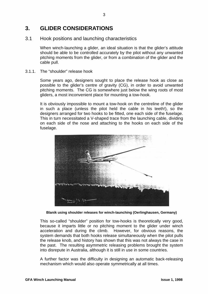
Blanik using shoulder releases for winch-launching (Oerlinghausen, Germany)
This so-called “shoulder” position for tow-hooks is theoretically very good, because it imparts little or no pitching moment to the glider under winch acceleration and during the climb. However, for obvious reasons, the system demands that both hooks release simultaneously when the pilot pulls the release knob, and history has shown that this was not always the case in the past. The resulting asymmetric releasing problems brought the system into disrepute in Australia, although it is still in use in some countries.
A further factor was the difficulty in designing an automatic back-releasing mechanism which would also operate symmetrically at all times.
GFA Winch Launching Manual Issue 1, 1998

4
3.1.2. The “belly” release hook
Instead of using shoulder releases for winch-launching, the accepted method is a single hook placed under the belly of the glider. As a general principle, winch launching should only be carried out using the “belly” hook, never the nose hook. The position of belly hooks varies from one glider type to another, some being way back under the pilot, others being further forward.
3.1.3. Unwanted pitching moments
Any belly-mounted hook must of necessity be displaced some distance underneath the glider’s CG. Therefore, unlike the shoulder-release system, a belly-mounted hook will, due to the glider’s inertia, impart a nose-up pitching moment about the glider’s CG under winch acceleration during the time when the glider is substantially level and not in a climbing attitude (e.g. during the ground-run and initial separation). The factors affecting the amount of pitch-up which will be imparted to the glider, and the extent to which any such pitch-up will be able to be controlled by the pilot, are :-
1. How far in front of the glider’s CG the hook is mounted. The further back the hook, the more the pitch-up tendency.
2. How far underneath the glider’s CG the hook is mounted. High-wing gliders, with high CG positions, tend to be the worst offenders.
3. The rate at which the glider is accelerated at the start of the launch. The greater the acceleration, the greater the tendency to pitch up.
The diagram above (reproduced with acknowledgement to “Sailplane and Gliding”) shows the effect of winch pull at the start of the launch. The line of the pull is very low with respect to the glider’s CG, imparting a strong pitch-up moment.
GFA Winch Launching Manual Issue 1, 1998

5
This diagram (again with acknowledgment to “Sailplane and Gliding”) shows the situation in the climb. The line of the winch pull now passes much closer to the CG and the pitch-up tendency is considerably reduced. In addition, acceleration has now ceased and the glider is at a steady speed, therefore inertia is no longer a factor.
Any pitching moment which may be present is resisted by a lift force from the horizontal stabilizer. A short tail-arm lessens the effectiveness of the horizontal stabilizer in controlling any pitch-up which does occur. Winch-drivers launching gliders like this (Ka8, Pirat, Junior and plenty of others) should be briefed to take it easy and not accelerate too rapidly.
Some degree of pitch-up tendency imparted by a belly-hook is not necessarily a bad thing, as the pilot will need quite a lot of down elevator to control the glider’s initial launch profile. Therefore if the cable breaks or the engine fails, the pitch-up moment is removed and the pilot already has down elevator to restore the glider to its normal nose attitude for a safe landing. However, it is important that the hook is not placed so far back that the pitch-up tendency is uncontrollable. It is also important that pilots realise the implications of their weight on pitch-up tendencies. The lighter the pilot, the more marked the pitch-up tendency.
If the belly hook is mounted a long way forward, there will be little or no pitch-up as the launch accelerates. In this situation the pilot may well have to use some “up” elevator to obtain the required launch profile. If a failure occurs, the glider will be in a nose-up attitude, but this time with the elevator up instead of down. The pilot will need to react very quickly if the glider is to be restored to the required attitude for a safe landing.
3.1.4. “Porpoising” on the launch
Mounting a belly hook too far forward creates another problem. From about the half-way point of the launch onwards, as the cable pull becomes increasingly downward, the pilot needs a lot of back stick to keep the nose up. The horizontal stabilizer reaches a critical angle and stalls the “wrong” way round (i.e. inverted) in the downwash from the wing. This sets up a pitching oscillation, or “porpoising”, which grows progressively more violent if
GFA Winch Launching Manual Issue 1, 1998

6
the pilot keeps the stick back. It is a most unpleasant phenomenon, but can be fixed immediately by easing the stick forward a little. Some gliders (e.g. Slingsby T31, Schneider Boomerang and Super Arrow) do this sort of thing all the time and such gliders are known for not getting much height on winch-launches. This has led to a modification to move the hook back a little in some designs. Naturally such a modification should not be done without airworthiness approval.
Both extremes of hook position should be avoided by basic design. A hook mounted too far back (especially on a deep fuselage) could result in such a strong nose-up pitch that it would be uncontrollable and the glider would be pulled into a steep climb near the ground whether the pilot wanted it or not. Too far forward and it might not want to climb at all and would leave the pilot exposed to the risk of having a lot of up elevator applied if a failure occurred near the ground.
A designer chooses the belly hook position carefully and the glider is flight-tested on the winch in all permissible CG positions. It will only obtain a Certificate of Airworthiness for winch launching if it shows no dangerous tendencies over the entire range of CG positions and launching speeds.
3.1.5. Other unwanted moments
Some gliders are fitted with a nose-skid as part of the main undercarriage assembly. In this case the belly-hook has to be offset to one side, as the skid occupies the space where the hook would normally be mounted. Examples of this kind of glider are short-wing Kookburra, K7, K8 and ASK13.
Even though the hook may be only about 10cms off the centreline of the glider, a surprisingly large swing can be produced if the winch accelerates very rapidly at the start of the launch. Although this is usually quite manageable, many pilots will recall leaving the ground with quite a lot of left rudder in a Kookaburra when being launched by a ham-fisted winch-driver. Pilots flying gliders with offset hooks are advised to be well prepared to put some effort into keeping straight on take-off.
3.1.6. Automatic back-release
There is an important design feature built into belly hooks. This is an automatic over-ride, or “back-release” mechanism, which will function if the glider flies too far overhead the winch. Thus, even if the main release mechanism is disabled inside the glider (for example, if the connection between the release knob and the belly hook should break, not entirely unknown), the back-release mechanism will function and automatically release the launching cable when the glider gets overhead or nearly-overhead the winch. If there is such a thing as a foolproof device, the back-release mechanism is as close as we are going to get.
Nose-mounted aerotowing hooks generally do not have back-release mechanisms, although there are exceptions such as the Blanik and IS28B2. It is best to assume that a back-release is not fitted to ANY nose hook and
GFA Winch Launching Manual Issue 1, 1998
7
on that basis to ensure that you never attempt a winch launch using one of these hooks. If you do, your last line of defence against a defect in the hook or its installation is removed.
3.1.7. Predicting likely launch characteristics
A pilot can predict the likely launch characteristics of a glider by standing back from it and eyeballing its general shape and hook position. A deep fuselage (implying a rather high centre of gravity) and aft-mounted hook equals a strong pitch-up on launch. Check out the tail-arm too - a short-coupled glider like a Pirat, which also has a deep fuselage and a very aft-mounted hook, is likely to be quite a handful on a winch take-off, especially with a lightweight pilot aboard. Make sure winch-drivers are briefed not to give such gliders very rapid acceleration. A shallow fuselage and hook not so far back will not produce so strong a pitch-up on take-off.
3.1.8. Useful tips
Use of soft cushions
Ensure that no soft cushions are placed behind pilots for winch-launching. Under acceleration, such cushions compress and allow the pilot to move back in the cockpit. This has three effects:
4. It moves the CG back, maybe only slightly but enough to cause trouble.
5. The pilot may involuntarily move the stick back as he/she moves back.
6. The pilot may be unable to reach the release knob after moving back.
Minimum pilot weight
If a pilot is on or near the minimum permissible weight to fly the glider, it is wise to add some extra cockpit ballast, especially if the glider is known to be demanding in its pitching characteristics.
Careful attention to seating position
Choose the seating position carefully. There is merit in positioning the pilot one notch further forward than appears to be necessary, anticipating a small amount of movement under acceleration. Similarly the rudder pedals could be brought back one notch.
Awareness of poor harness design
Some gliders (e.g. Std Cirrus and its variants) may allow the pilot to slide backwards and upwards along the seat once the glider is established in the full climb. This is a function of the very smooth seat and the particular design of the seat harness. The effects are the same as for compressible seat cushions. A simple modification, such as fitting some Velcro to the seat pan to increase friction, may help to prevent this disturbing tendency.
GFA Winch Launching Manual Issue 1, 1998
8
3.1.9. Final reminders
Attempting a winch launch on the nose (aerotow) hook forfeits the safety-net of the automatic back-release mechanism and needs considerable up elevator to maintain a climb. The pilot is very vulnerable if a cable or winch failure should occur in the early stages. Don’t try it.
It is the PILOT’S responsibility to ensure that the launching cable is attached to the correct towhook. Pilots should not try to blame the ground-crew if an error is made.
Take care in setting up the cockpit exactly as required to ensure safety in winch-launching.
Talk to the Instructor’s Panel and Committee about throwing out any soft cushions which have been used as cockpit padding.
3.2. Winch-launching loads and launch-speed boundaries
Winch launching is potentially stressful for a glider’s structure. The reason is not particularly obvious and needs a detailed explanation.
We start by considering a glider about to carry out an aerobatic manoeuvre in free flight, in this case a loop.
3.2.1. Winch-launching loads
In free flight, when a glider is pulled up into a looping manoevre, the wings produce much more lift than they usually do. This is at the command of the pilot, who firstly dives the glider for excess speed (thus producing more lift by increasing the airflow over the wings) then eases the stick back to pull the nose up (thus producing even more lift by increasing the angle of attack of the wings). The glider therefore has a good supply of lift to enable it to fly around the curved manoeuvre without stalling.
As the wings produce this greatly increased amount of lift, they naturally bend upwards under its influence. This places considerable stress on all components in the wings, but especially at the wing roots, where all the forces generated in flight accumulate. The bending stresses at the wing roots of a glider during aerobatics are considerably higher than in non-aerobatic flight.
In the situation described, the pilot feels “G” loads as the manoeuvre develops. This feeling is normal in all aerobatic manoeuvres and the values of G typically felt by a glider pilot will be in the order of 2 to 3. This means the pilot is feeling 2 to 3 times his/her own weight (we are all at 1 G in normal circumstances). Anything more than 2 to 3 is usually unnecessary and G values of over 4 may be regarded as somewhat excessive in gliders.
GFA Winch Launching Manual Issue 1, 1998

9
3.2.2. Wing bending relief
It follows that, if the pilot feels 2 to 3 times his or her own weight during a manoeuvre, so does every component of the glider. Every part of the wings, fuselage and tail of the glider experiences this G force.
As the wings are bent upwards by the increased lift, the G forces (pulling in the opposite direction) try to straighten them out again as the manoeuvre develops. Thus the G forces produce a measure of bending relief for the wings, which is very useful in protecting the structure from being overstressed.
With lift pulling in one direction and being directly opposed by G forces pulling in the other direction, it will be seen that aerobatics, although more stressful than non-aerobatic flight, are quite capable of being absorbed by the glider, as G forces tend to prevent the glider’s wings from being bent beyond their limit. This is obviously only true if the glider is rated for aerobatics and is flown within its placarded limitations.
3.2.3. The relevance of bending relief to winch-launching
What has all this to do with winch-launching? Well, there are two similarities between a winch-launch and a glider doing aerobatics. One is the excess speed (over and above, say, min sink speed), the other is a higher than normal angle of attack (again relative to the min. sink situation). On a winch-launch the speed is at least 1.3 Vs and is usually higher than that, and the angle of attack in the full-climb phase of the launch may be as high as 9 or 10 degrees. The combination of the two produces plenty of lift, enough to give a peak rate of climb during the full climb part of somewhere between 2,000 and 3,000 feet per minute (20 to 30 knots).
During a winch-launch, a glider is tethered by its belly, being attached to the launching cable by the belly hook. Tethering the glider prevents it from moving into a curved “looping” manoeuvre, which it would naturally want to do if it were untethered. As the glider is not following a curved path around a loop, there are no G forces being produced and this is borne out by the fact that a pilot feels no G during a winch launch.
If there is no G, there is no bending relief for the wings. They are producing about the same amount of lift as they would for a 2 to 3 G looping manoeuvre, but the looping manoeuvre is being prevented by the cable and the glider follows a more or less straight climbing path. Thus the wings bend, and are not being straightened out again by any G forces.
The net result of this is twofold :-
1. The bending moment around the wing roots is unrelieved and is therefore rather high.
2. The pilot feels no additional G forces and tends not to realise that the wings are being subjected to these higher bending moments.
GFA Winch Launching Manual Issue 1, 1998

10
Refer to the two diagrams overleaf.
3.2.4. The purpose of the weak-link
Because of these two points, it would not be difficult for the pilot to produce bending moments about the wing roots which are higher than those intended by the designer. Excessive bending moments may be produced by flying the glider in excess of its placarded maximum launch speed or by pulling back excessively hard on the stick, or by a combination of the two.
To guard against this eventuality, it is a feature of the certification of gliders that a “weak link” be fitted in the launching cable for the protection of the glider against overstress. The maximum breaking strength of the weak link is placarded in the cockpit and repeated on an external notice near the belly hook. Failure to use a weak leak of the specified maximum breaking strength compromises the certification of the glider and, more importantly, puts the pilot at risk through overstressing of the glider to the point of structural failure. The weak link fulfils the same function as a fuse in an electrical system.
Free flight, pulling up into a looping manoeuvre. About 2½Gs-worth of lift being produced, tending to bend the wings upwards. 2½Gs-worth of wing-weight, creating
a relieving force tending to straighten wings out again.
GFA Winch Launching Manual Issue 1, 1998

11
In full climb on a winch-launch. About 2½ Gs-worth of lift tending to bend wings upward. Because glider is tethered by its belly and thereby prevented from entering a looping manoeuvre, there is only 1Gs-worth of wing-weight trying to straighten them out again. In addition, the cable is being pulled into the winch, creating a downward force which is acting centrally on the fuselage and is reacted by “up” elevator. The
overall result is a more severe bending moment about the wing roots.
3.2.5. Launch-speed boundaries
3.2.5.1. Maximum speed
The permissible maximum speed for winch-launching is quite restricted and is usually the lowest of all the speed limitations imposed on the glider. The reason, as explained in the previous section, is because the glider is tethered by its belly, thus allowing more wing-bending to take place than in normal flight. Limiting the maximum speed during winch-launching puts an upper limit on the amount of wing-bending which is likely to occur. The maximum winch-launch speed (known as Vw) is placarded in the glider cockpit.
A word of clarification is appropriate in relation to the maximum speed limit. We know that this limit is imposed for structural reasons, specifically wing-bending. The conditions conducive to wing-bending are at their worst in the second half of the launch, where cable-pull is added to gravity and the pilot may need a lot of back stick to produce enough lift to counteract the combination of the two forces and keep the glider climbing. If the maximum placard speed is exceeded at this point, enough force will be generated to break the weak link. If a weak link stronger than specified is being used, or even worse if no weak link at all is fitted, the glider can easily be overstressed. The maximum placard speed must never be exceeded once the glider has passed about the half-way mark of a launch.
There is a bit more freedom lower down. At the beginning of a launch, with the cable-pull almost parallel with the ground, there is very little extra load on the wings over and above the loads applied in normal flight. Even at cable-
GFA Winch Launching Manual Issue 1, 1998
12
to-ground angles up to about 25º and the glider in full climb, it can be shown that the loads remain acceptable. Exceeding the maximum placard speed is really not very harmful during these stages and it is acceptable to tolerate a small excess (say 10%), progressively steepening the climb angle while the winch-driver sorts himself out and adjusts the speed. If excess speed remains when the full climb has been attained, the standard “too fast” signal can be given or the launch abandoned if it appears to be really getting out of hand.
Glider pilots sometimes (too often?) climb steeply close to the ground, offering as an excuse one of three reasons, viz:-
1. “I had plenty of speed, so it was safe to climb steeply”. WRONG!
2. “I am experienced and current, and would instantly recognize a failure. WRONG!
3. “I had too much speed, so I pulled back to try to kill it”. WRONG!
Climbing excessively steeply near the ground is never acceptable, whatever the excuse. It is much safer to allow small inroads into the maximum launch speed in the early stages, while controlling the climb angle so that it steepens progressively in the normal way, than to pull the nose up close to the ground.
History shows that pilots do not recognize launch failures as quickly as they think they do. The known delay in realising that a failure has occurred can prove fatal if the nose is so high, and the ground so close, that recovery cannot be made in time.
3.2.5.2. Minimum speed
The permissible minimum speed for winch-launching is not placarded and is based on a value of 1.3 times the stall speed (1.3 Vs). The stall speed to be used is the one applicable in the configuration in which the glider is being launched. As well as varying with glider weight, stall speed also varies with flap settings in the case of gliders fitted with these devices.
Going back for a moment to the cable-pull discussion in the previous section, this has an effect on the minimum speed too. In the early stages of the launch, with the cable-pull nearly parallel with the ground, the wings are not loaded much above normal flight and the stalling speed is pretty much the same as in normal flight too.
As the launch progresses and the cable pull approaches closer and closer to the vertical, the loads on the wing increase and the stalling speed increases accordingly. Near the top of the launch the increase can be as much as 30%, which takes the stall speed to 1.3 Vs. This just happens to be the speed we choose as our minimum speed to fly a winch-launch.
It follows that the logical action to take is to reduce the back-pressure on the stick as the top of the launch is approached. In fact we go even further and
GFA Winch Launching Manual Issue 1, 1998

13
modern winch-launch training calls for a gradual forward movement on the stick towards the top of the launch. This is in contrast to the “stick back in the guts” technique of past years, where it was considered the right thing to do to get the last inch of height out of the launch. In reality, it is probably only an inch that will be gained, because the biggest proportion of the total height obtained on a winch-launch is gained in the early stages, immediately after the full climb has been attained. This is not an argument for excessively early rotations into full climb, but for trying to persuade pilots that clutching the stick back in the guts at the top of the launch will not make a jot of difference to the height gained.
For those pilots who might still be tempted to use this old-fashioned technique, think about this. Even if the risk of stalling on the wire is considered to be worth taking at that height, and even if you don’t really believe that you won’t get a bit of extra height out of it, think about the poor old winch-driver when the glider breaks the weak link and sends hundreds of metres of very badly-behaved spring-steel wire hurtling downwards. Even if the winch’s protective devices work and the driver is unharmed, it is likely that he will spend the next hour sorting out the mess the pilot created. He will almost certainly nominate you for the club’s pain-in-the-arse award after that experience.
4. PILOT CONSIDERATIONS
4.1. Correct launch technique
The correct launch technique allows the glider to separate from the ground in a natural flying attitude and then (provided the speed is above the minimim 1.3Vs) to enter a graduated climb profile, becoming steeper as height is gained.
4.1.1. Ground-run and separation
The “natural flying attitude” on the ground varies from type to type, as does the means by which the pilot uses the controls to adopt that attitude.
4.1.1.1. “Taildragger” gliders
Most gliders of “taildragger” layout are already at or very close to the natural flying attitude on the ground and the only action needed by the pilot is to be ready for separation to occur and anticipate any minor corrections that may be needed to either prevent an excessively steep climb developing or give some assistance to the glider to enter a gentle climb, depending on a number of factors such as rate of acceleration, etc.
Some pilots prefer to raise the tail off the ground during the ground run, then use a small back movement of the stick to get the glider into the natural flying attitude, following which it will usually lift off cleanly. The advantage of doing this is that enables the pilot to feel at what point during the ground-run the elevator becomes effective. The disadvantage is that it requires a fair degree of finesse to return the glider to the natural flying attitude. It can also,
GFA Winch Launching Manual Issue 1, 1998

14
if mishandled only slightly by a pilot who over-reacts to the nose going down too far, cause the glider to “over-rotate” into an excessively steep climb at too low a height, especially if the acceleration is rapid.
The essential point is that the glider should leave the ground in a natural attitude and should not be allowed to steepen its climb until the speed is confirmed to have risen to the minimum safe value.
4.1.1.2. “Nosedragger” gliders
Gliders of nose-heavy layout, will usually “self-rotate” into a tail-down attitude under winch acceleration. If the acceleration is fierce, the tail might bang down very hard. The pilot should anticipate this and start the take-off run with the stick well forward in this type of glider. When the actual accleration starts and the pilot has felt what it is like, the control actions can be refined to get the glider into the natural flying attitude.
The same comments apply to the nosedragger as for the taildragger, with respect to the glider leaving the ground in a natural attitude and only being allowed to steepen once the speed has increased to the minimum 1.3Vs.
4.1.2. Initial climb
Once the glider is clear of the ground, differences in undercarriage layout are no longer relevant and all gliders are treated identically for the remainder of the launch.
In the initial climb phase the pilot controls the glider in such a way that the climb angle progressively increases as height is gained, the speed being somewhere between the minimum of 1.3 Vs and the maximum placarded value.
The natural tendency of the glider at this stage of the launch will vary depending on its design features, the CG position (mainly a pilot weight consideration), the rate of winch acceleration and whether or not there is a wind-gradient. Some gliders will try to “self-steepen”, in which case the pilot will need to resist this tendency and restrain the climb angle to achieve the necessary graduated profile. Other designs may be more reluctant to steepen and such gliders may need a little help from the pilot to steepen the climb in order to achieve the required profile.
The main point is that the initial climb profile must be positively controlled by the pilot, unless by happy coincidence the glider is following exactly the correct profile of its own accord. This is not often the case, but unfortunately too many pilots allow the glider to “do its own thing” without exercising the required amount of control over it.
The more height you have, the steeper you can afford to be. If the pilot steepens the climb progressively as height increases, and if the speed remains at a safe value, the initial climb technique is correct. Keep doing it this way.
GFA Winch Launching Manual Issue 1, 1998

15
Glider attitude accurately controlled. Do not climb steeply at too low a height. Make changes to climb angle smoothly and progressively, gradually steepening the climb as height builds up.
Speed greater than 1.3Vs, permissible to exceed the placarded maximum by about 10% at this point in the launch
Correct initial climb
4.1.3. The maximum speed placard and the initial climb
Previous sections of this manual referred to the maximum placarded winch/auto speed (Vw) and the fact that this speed is intended to protect the structure against being overstressed on the launch. The point was made that the loads on the glider during the early part of the launch are not much more than in level, untethered, flight.
If too much speed is noted during the initial climb, it is better to continue graduating the climb until the glider is established in the full climb at a safe height than to climb the glider too steeply near the ground in an attempt to “load up” the winch engine. When the glider is safely established in the full climb, the pilot can then take stock and see whether action (e.g. signals, abandoning the launch) is then necessary. The only proviso here is that the speed has not become intolerably high during the initial climb, say more than 10% higher than Vw. If the speed does get intolerably high, the decision has to be made whether to give a “too fast” signal before the full climb or abandon the launch there and then.
If the launch is abandoned during the initial climb phase, two things apply:
1. The winch/car driver may not be able to “feel” the glider on the end of the wire in the early stages of the launch before the full climb has been reached. If the launch is abandoned, the driver may not realise it straight away and may not cut the power promptly. Drogue parachutes (if fitted) can become quite unstable under these conditions and their behaviour is unpredictable. If the drogue decides to oscillate, the glider may become entangled.
2. The winch/car driver may not be able to see the glider because of ground clutter and/or strip curvature. This adds to the lack of feel and offers another opportunity for entanglement in a cable drogue.
GFA Winch Launching Manual Issue 1, 1998
16
All things considered, it is best to stay on the wire if possible (provided of course that the speed is not trending towards too SLOW, or is not outrageously fast), and grade the climb carefully until the driver can see and feel the glider’s presence, then assess the options and act accordingly.
4.1.4. Full climb
The full climb presents no great difficulties. Direction is monitored by looking each side of the glider’s nose (clouds are handy for this too), climb angle is determined by looking under the wing and the wingtips are checked in turn to see if the glider is level laterally (but see 4.1.8).
It is quite safe to climb steeply once the glider is properly established in the full climb. The principal height gains are made in this early part of the full climb, so get the maximum benefit out of it by optimum utilisation as soon as you safely can. You won’t be able to make up for any losses higher up the launch.
Speed should be kept between the minimum (1.3Vs) and the placarded maximum, the region known as the “working speed band”. Glider speed is basically determined by the winch-driver, pilot technique making relatively little difference. There are exceptions to this, such as a very low-powered winch, where pulling back on the stick results in engine revs decreasing and the speed decaying. However, there are not many low-powered winches left nowadays and it is a mistake to think that launch speed can be controlled in this way.
Rather, the opposite is the case. Pulling the stick further back in the full climb when being launched by a powerful winch can result in the speed actually increasing. This is the “arc of a circle” argument familiar to water-skiers, where following a line outside that taken by the ski-boat will cause the skier to increase speed because of the longer distance which has to be travelled.
It is good practice on the part of the pilot to develop the habit of relaxing the back-pressure on the stick if the speed falls, and increasing the back-pressure if the speed rises, provided of course the speed remains within the working speed band.
As height is gained and we pass the half-way point of the launch, we enter the region where there is an increasing downward pull on the cable. This results in an increase in stalling speed and an increasing amount of stress on the wings. From this point onwards, we need to be more conscious of the loads applied to the glider and ensure that speed limits are conscientiously observed.
When approaching the top of the launch, it is prudent to start relaxing any back-pressure on the stick, translating this into a forward movement as the nose is pulled level with the horizon by the cable. This ensures a clean release and minimises any chance of breaking the weak link and/or cable.
GFA Winch Launching Manual Issue 1, 1998
17
The top of the launch is the most likely place to break the cable or weak link. Cable pull combines with gravity to maximise the strain in the wire. Faulty pilot technique, in the form of keeping the stick right back, will very likely cause a break at this point. This is the kind of break which is very hazardous to winch-drivers as the spring-steel wire descends upon him.
4.1.5. The maximum speed placard and the full climb
There is no leeway in the maximum winch-launch speed in the full climb.
4.1.6. The effect of the weight of the wire
The nominal mass of 3.15mm range 2 spring steel wire is 0.0611 kgs per metre. The weight of a 1500 metre length of wire is therefore 92 kgs. By the time the glider is near the top of the launch, there will be somewhere between 500 and 700 metres of wire hanging from its belly, which amounts to an extra weight of 31 to 43 kgs added to the fuselage.
The figures for the slightly thinner 2.8mm range 2 spring steel wire are between 24 and 34 kgs for the same wire lengths. For 5mm 7 x 19 wire rope (stranded cable), the figures are between 48 and 67 kgs.
4.1.7. The release
At the top of the launch the winch driver will close the throttle quite noticeably and at this time, one of two things will happen. Either the cable will back-release or the launch will become noticeably “slack”, with a fall-off in speed and no more upward progress. In both cases, the pilot’s action is to establish a normal flying attitude and pull the release twice.
Use of the back-release in normal launching is quite acceptable. However, pilots must ALWAYS be taught to pull the release twice, to be certain the cable has gone.
4.1.8. Winch-launching in crosswinds
The maximum height on a winch-launch is obtained if no correction is made for crosswinds and the glider is allowed to drift with the wind. However, this technique will earn the pilot no friends and may be dangerous if there are powerlines in the vicinity. It is normal practice to make some kind of correction for crosswinds.
This can be done in one of two ways. The glider’s wing can be lowered into the wind and a touch of opposite rudder applied, thus effectively sideslipping the glider into the wind. The alternative is to lower the wing and apply the same rudder, altering the glider’s heading so as to offset the drift. The second one is probably the tidier of the two and it is usually more effective, especially in strong crosswinds.
Crosswind correction should be applied as soon as the glider is clear of the ground. If you wait until the full climb, it will usually be too late and the cable
GFA Winch Launching Manual Issue 1, 1998

18
will probably drift outside the airfield after release, the winch-driver being powerless to prevent it.
4.1.9. Launch speed signals
Too slow
If the speed falls below the optimum but has still not fallen to the 1.3Vs minimum, the “too slow” signal may be given by lowering the nose of the glider and rocking the wings from side to side with coordinated aileron and rudder. If speed does not increase, release.
Too fast
If the speed is showing an upward trend and does not appear to be stabilising, a “too fast” signal may be given by yawing the glider from side to side, taking care not to let the secondary effect of rudder produce any roll which may confuse the winch driver.
4.1.10. Kiting
Because of the hazard to the general public, the “kiting” of gliders on a winch launch (i.e. the paying out of cable in order to increase launch height) is prohibited.
4.2. Incorrect launch techniques
4.2.1. Holding the glider down
We know that a good launch starts by climbing gently away from the ground after separation, the glider’s climb angle (or flight path, if you prefer) being progressively steepened as height is gained.
We have discussed the pitfalls inherent in climbing too steeply too close to the ground. There is no need to labour that point any further here.
Another common fault in learning the winch launch is to separate normally, then hold the glider’s nose down in an excessively flat attitude immediately after separation. This is usually done in error, while a pilot develops the “feel” for the correct attitude and how to achieve it. Such errors in learning are quite understandable and instructors and winch-drivers have no great problem in overcoming them.
However, there are some pilots who genuinely think that holding the glider down, then “rotating” into the climb, is the correct technique to use. This is a mistake, for the following reasons:-
1. The winch-driver cannot feel the glider in the early stages of the launch, because negligible load is being applied to the winch. He/she therefore does not know whether too much or too little power has been applied.
GFA Winch Launching Manual Issue 1, 1998

19
2. The winch-driver usually cannot see the glider because it has not risen above ground clutter. This is especially true if the background consists of high ground or trees or in the “mirage” effect typical of summer conditions.
3. In most cases, it will almost certainly guarantee that the glider will grossly overspeed.
4. If a climb is then suddenly commenced, the excessive speed and consequent sensitive elevator control will make it very difficult for the pilot to control the glider’s attitude accurately and a very steep climb may occur very suddenly, especially if the glider is known to be pitch-sensitive and/or has a very aft-mounted hook.
5. A combination of 3 and 4 above will probably result in a low-level cable break due to the sudden application of load to the cable.
It will therefore be obvious that a smooth, progressive transition into the full climb is preferable to the stepped technique, from both the pilot’s and the winch-driver’s viewpoint.
4.2.2. Allowing the glider to “self-rotate”
Another common problem relates to the tendency of some gliders to pitch-up of their own accord under the influence of winch acceleration. We know the reasons for this from the first section on glider considerations.
A pilot who fails to counteract this tendency, by “restraining” the climb angle with forward pressure or even a definite forward movement on the stick, will find the glider climbing more and more steeply as speed builds up. This will often occur before sufficient height has been gained for a steep climb angle to be considered safe.
The tender trap here is that it feels so natural for the glider to be entering the climb of its own accord that the pilot may not smell a rat and take some action to restrain it. Some of these “self-steepenings” are rather subtle and must be monitored very carefully by the pilot. Others are very obvious and you would have to be an idiot not to detect that things are getting out of hand.
Each launch is a little bit different from the one before. Winch-driver technique, wind velocity, wind-gradient are just some of the factors making for variety in launches. There is no alternative but to closely monitor the climb profile of EVERY winch take-off and not assume that the next one will be similar to the last one.
The tendency to allow the glider to take charge of the pilot during this critical phase of flight is known to have been responsible for a number of accidents, some of them fatal, in Australia and overseas. The Germans, the most experienced winch-launch pilots in the world, call this particular error “letting the winch take-off happen to the pilot”.
GFA Winch Launching Manual Issue 1, 1998

20
4.2.3. The “Kavalierstart”
We look to the Germans again for an apt expression to describe excessively steep winch take-offs. The “Kavalierstart” term was coined after a very bad run of winch-launch accidents in Germany in 1995, during which there were 32 accidents in this phase of flight, 12 of which were fatal.
A Kavalierstart means simply treating the winch take-off in a cavalier (= arrogant, or “an accident can’t happen to me”) manner.
The remedial treatment for pilots who do this kind of winch take-off is to bring the matter to their attention. This should be repeated, ad nauseam if necessary, until the pilot gets the message. It doesn’t matter who brings it to the pilot’s attention. It doesn’t have to be an instructor, in fact it is probably more effective coming from a pilot’s peers. It is a serious mistake to let these things go without comment.
If the pilot does not get the message and persists in using the Kavalierstart technique, that pilot is living on borrowed time and will eventually have an accident which will probably be serious or fatal.
If it proves impossible to reason with the pilot and neither advice nor check flights do the trick, it is kinder to refuse to launch that pilot until he/she sees reason than to turn a blind eye and run the risk of a terrible accident.
4.3. Launch failures - Philosophical and training considerations
4.3.1. Introduction
No system is foolproof. Aircraft engines fail, pilots run aircraft out of fuel and they also make simple errors of judgement or skill. Similarly winch problems of various kinds occur from time to time.
Winch cables break from time to time. Winch engines also run out of fuel, just like aircraft engines do. Such occurrences should not in themselves result in a serious accident, as all the failure cases are well-known and training strategies are in place to deal with them. Nevertheless accidents do occur and we are forced to ask why.
The answer is twofold. Part of it lies in human factors, the “nut behind the wheel”. The other part lies in the training system itself and whether this provides an adequate level of protection for a pilot when something abnormal occurs.
In this section, the philosophical approach to launch failures will be examined, as will all aspects of the training of pilots.
4.3.2. The mental approach to launch failures
In the early days of light aircraft, when aero engines were rather unreliable, there were many failures, but the good side of the story was that almost every forced landing was successful because the pilots got plenty of
GFA Winch Launching Manual Issue 1, 1998

21
practice. A similar pattern emerged with the advent of ultralight aircraft, the original unreliable two-strokes giving pilots ample forced-landing practice and resulting in a relatively low injury and fatality rate.
Nobody would seriously argue that poor, unreliable equipment forms the basis for a high level of safety. Unfortunately there used to be some people who appeared to believe this. Such people would argue that, because their club had quite a lot of cable breaks in any one year, they did not need to formalise the training of launch failures, despite the random distribution of such breaks, one pilot getting seven or eight in a period of time, others getting none at all. Some of these clubs thought they really were doing a good job.
Nevertheless, when equipment is of a good standard and breakdowns are few, there is a temptation to avoid deliberately inducing failures, as they cause inconvenience and some would say they negate the effort put into making it reliable in the first place.
The ideal training system consists of reliable equipment which is used in a sensible way to create realistic simulations of failures. Pilots then get used to the idea that all the failure cases will be covered during training and revisited during periodic check flights.
There is another aspect of launch-failure training. It is possible to partially simulate the behaviour of a glider following a launch-failure by diving to gain excess speed, pulling up to a simulated winch-launch angle, say 40 degrees, then pushing over and (a) seeing how long it takes to achieve a safe speed after the pushover and (b) how readily the glider spins if an attempt is made to manoeuvre at this point.
Valuable as this exercise it in its own right, it is not a complete simulation of all aspects of launch-failures. It is a GFA requirement (Ops Manual, white pages, section 22.1.9.) that launch-failures are simulated DURING THE LAUNCH, and reliance must not be placed on the dive-pullup-pushover exercise alone.
4.3.2.1. Detecting a failure
One of the most common excuses given by a pilot to justify a very steep take-off is the fact that he/she is experienced and in current flying practice. This is translated in the pilot’s mind into an automatic ability to detect any failure the very instant it occurs and produce the correct response to it, thus saving the situation.
In reality most pilots do not react as quickly as they think they will to emergencies such as launch failures. The human “computer” is rather slow, 1975 simulator studies showing that the average time from engine failure to brake application in an aborted take-off situation is between 4 and 5 seconds (GFA Instructor’s Handbook, Part 1, page 7). This time is taken up by mental realisation, physical reaction and control response. It takes no account of aircraft inertia, which is covered on page 28.
GFA Winch Launching Manual Issue 1, 1998

22
The time taken to recognise a launch failure can be readily confirmed by check flight, where the failure can be contrived under controlled conditions. Without going into detail of all the various failure cases, which are the subject of another section of this manual, it is sufficient to say here that, to be safe, pilots must accept that there will be a delay between a failure occurring and the pilot realising that it has occurred.
4.3.2.2. Expecting a failure
This is a key point. A skilled pilot always EXPECTS a failure on each take-off. Nowadays this extends to incorporating the expectation of a launch failure into the pre-take off check, the “O” in CHAOTIC standing for “Options” as well as “Outside”.
Expectation of a failure on each launch creates a mental preparedness to deal with it, the primary action and the various options having been considered before take-off. If the failure occurs, there is no mental barrier to overcome; if it doesn’t occur, the pilot can feel pleased with a successful launch.
Only if a pilot is expecting a launch failure can the reaction time be reduced to manageable proportions. This is known as defensive flying and it is the answer to safety management in winch-launching.
Expecting a failure is a key point. Always be prepared for a launch failure. No-one is immune from the time delay inherent in detecting a
failure and reacting to it.
4.4. The physical characteristics of launch-failures
Launch-failures fall into two main categories, cable-breaks and engine-failures. They both rather obviously result in termination of the launch, the cable-break being an abrupt occurrence, the engine-failure perhaps being more subtle.
4.4.1. Cable breaks
Regardless of the type of wire, cable or rope being used, breaks can occur suddenly and randomly. Solid wire is prone to fatigue due to constant bending and straightening and gives no warning of impending failure. Stranded cable (wire rope) gives a bit more of a hint by revealing loose strands or an incipient bird’s nest, but this can only be of use as a warning if it happens to occur where someone on the field can see it. The suddenness of cable failure, together with the lack of warning, accounts for why the mental approach to launch failures places so much emphasis on always being prepared and never assuming that it won’t happen to you.
The other aspect to consider is that the weak link may break. This is designed to protect the structure, but the result is a sudden failure of the launch which is identical in all respects to a cable-break.
GFA Winch Launching Manual Issue 1, 1998

23
Because the speed margin above the stall is small and the climb angle may be steep, the pilot must react promptly to a cable-break and lower the nose smartly to at least the “approach to land” attitude and allow the speed to build up to a safe value. The two types of cable-break to consider are as follows:
Low-level
If the failure occurs low down, below say 200 feet, the climb angle will not be (or should not be) very steep and the lowering of the nose is not an extreme manoeuvre. The speed should not decay very much during the “pushover” from the climb to approach attitude and there is no great inertial problem to overcome, as the glider does not have to climb to the apex of a steep “hill” then come down the other side to build up speed. This is the very reason the glider is not allowed to climb steeply during this phase. There is, however, one fly in the ointment, which is wind-gradient.
If there is a wind blowing, there will be a wind-gradient, the severity depending on the wind-strength. As the glider climbs, it enters an increasing wind strength and this effectively adds to the airspeed on the launch. This is a good bonus at this stage of the launch. However, if the cable breaks at this point and the glider’s nose is lowered, it has to descend through the wind-gradient and the speed will start to fall again. The pilot will need to control the glider’s attitude very carefully to strike a balance between maintaining an adequate margin of airspeed, yet not diving into the ground. Do not open the airbrakes until an adequate speed has been regained and they should not be opened at all if the glider is very low, or you will be rewarded with a heavy landing.
WHAT THE WIND-GRADIENT GIVETH ON THE WAY UP, IT TAKETH AWAY ON THE WAY DOWN.
High-level
The full climb stage of the launch is characterised by a very high climb rate, typically in excess of 2,000 ft/min (20 knots). Height is obviously gained very rapidly and it is quite safe to climb steeply during this phase, provided of course that the speed is safely within the working band.
If a cable-break occurs during this phase, the bad news is that the pilot has to take prompt and positive action to ensure that the glider’s nose attitude is changed from the steep climb attitude to the “approach to land” attitude necessary for re-establishing a safe speed. The good news is that there is sufficient height to do this safely, so there is no need to rush things. Prompt and positive is not the same thing as panic-stricken.
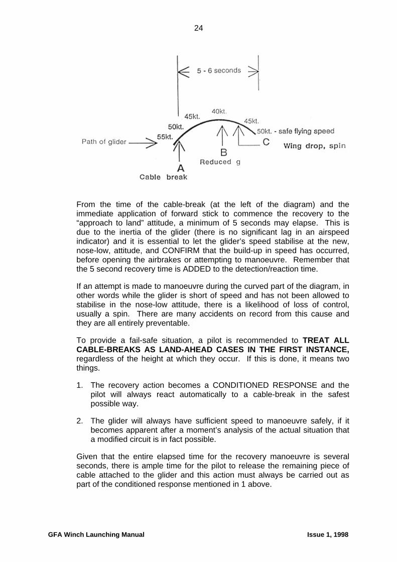
There are however two additional factors, jointly the most important of all and persistently responsible for causing winch-launch accidents year after year. The factors are inertia and time. Study the diagram below.
GFA Winch Launching Manual Issue 1, 1998
24
From the time of the cable-break (at the left of the diagram) and the immediate application of forward stick to commence the recovery to the “approach to land” attitude, a minimum of 5 seconds may elapse. This is due to the inertia of the glider (there is no significant lag in an airspeed indicator) and it is essential to let the glider’s speed stabilise at the new, nose-low, attitude, and CONFIRM that the build-up in speed has occurred, before opening the airbrakes or attempting to manoeuvre. Remember that the 5 second recovery time is ADDED to the detection/reaction time.
If an attempt is made to manoeuvre during the curved part of the diagram, in other words while the glider is short of speed and has not been allowed to stabilise in the nose-low attitude, there is a likelihood of loss of control, usually a spin. There are many accidents on record from this cause and they are all entirely preventable.
To provide a fail-safe situation, a pilot is recommended to TREAT ALL CABLE-BREAKS AS LAND-AHEAD CASES IN THE FIRST INSTANCE, regardless of the height at which they occur. If this is done, it means two things.
1. The recovery action becomes a CONDITIONED RESPONSE and the pilot will always react automatically to a cable-break in the safest possible way.
2. The glider will always have sufficient speed to manoeuvre safely, if it becomes apparent after a moment’s analysis of the actual situation that a modified circuit is in fact possible.
Given that the entire elapsed time for the recovery manoeuvre is several seconds, there is ample time for the pilot to release the remaining piece of cable attached to the glider and this action must always be carried out as part of the conditioned response mentioned in 1 above.
GFA Winch Launching Manual Issue 1, 1998

25
When the above actions have been carried out, the glider is as ready to land safely as it ever will be. It is now time to refine the judgemental aspects of the launch-failure to determine just where it is most appropriate to land it.
4.4.2. Land ahead or circuit?
This is one of the most crucial decisions a pilot will ever be called upon to make. However, the fact that it is crucial does not mean that it must be difficult. It is purely a function of training. Refer back to section 4.3, philosophical and training considerations.
Many accidents result from a decision to turn immediately after a cable-break, with the intention of joining some kind of circuit. The glider, short of speed because of its own inertia, does not have enough energy to attempt such a manoeuvre unless the correct recovery action has been taken and enough time has elapsed for it to take effect. The pilot, who may be under a fair bit of stress at this time, turns the glider as a kind of reflex action before the required amount of time has elapsed. It is worth examining how this reflex action became embedded in the pilot’s mind, to come to the surface at the worst possible moment.
There are several possibilities, any or all of which may be relevant.
1. An obsession with getting back to the launch point, based either on a feeling of shame associated with landing anywhere else on the field (“real pilots always get back to their take-off point”) or an underlying feeling that the launch point is familiar and safe, anywhere else being strange and threatening.
2. A feeling that landing down the field will cause much inconvenience and will prevent launching another glider for some considerable time.
3. The pilot lacks confidence that he/she can safely land ahead in the space available.
4. The pilot may feel that, although a landing ahead might be possible, it will need full airbrake and he/she has never done that before.
With respect to the first two points, a feeling of shame at landing anywhere other than at the launch-point is often a function of peer-pressure. People who ridicule any pilot for putting safety before convenience have a lot to answer for. Apart from remonstrating with the pilot’s “friends” who apply this kind of pressure, the only way to proof a pilot against behaving in this way under pressure is through correct and conscientious training. It is important to realise that it may take more training than we have traditionally allocated to this sequence.
The third point, lack of confidence to land ahead in the space available, is purely a function of training. If a pilot has never had to do this exercise during training, it is not surprising that confidence will be lacking when the
GFA Winch Launching Manual Issue 1, 1998

26
real thing occurs. The answer is obvious and again depends on proper and conscientious training. Convenience does not enter into it.
The fourth point, fear of using full airbrake, is more common than might be thought. It is again a function of proper and conscientious training.
Both the lack of confidence in landing in the space available and the fear of full airbrake can be covered in a useful simulation exercise, not related to launch failures but providing the necessary background to create confidence and remove fear. The simulation can be carried out during an ordinary routine circuit, where the instructor will define a space to be landed in, with particular emphasis on defining the end-of-roll, and then require the pilot to approach as closely to this area as he/she dares on final approach, without using any airbrake. It will get to the stage of looking impossibly high and steep, to the extent that a gross overshoot seems inevitable. It is at this point that the approach looks remarkably similar to what a pilot sees when a cable breaks in the full climb at, say, 400 feet, and the pilot has just pitched the nose down.
The airbrakes are now fully opened and the nose lowered to counteract the increased drag, whereupon the rate of descent builds up to the extent that a task which initially looked impossible is now looking much more feasible. As the exercise is completed and is preferably repeated a number of times, the pilot finds that he/she can in fact land in spaces previously thought unavailable. And all because the pilot had never done a full airbrake approach before, or at least not within recent memory.
It should be stressed to pilots that they are not expected to carry out every approach this way. It is another string to their bow if they should ever need it in an abnormal situation. As well as launch-failure, it could be beneficial in an outlanding, for example.
Although this exercise is very successful in most gliders, there are a few types (e.g. Salto, early Kookaburras) which have such feeble airbrakes/spoilers that its effectiveness is not as great. Briefing on this point should be a function of type conversion.
4.4.3 Inertial factors
The notion that airspeed indicating systems have a significant built-in lag is a fallacy. On a Daily Inspection, if someone blows gently into the pitot head, the effect on the ASI needle is instantaneous. The lag in speed indications during the recovery from a cable-break is not caused by the instrument, it is caused by the glider. Provided there is no slip or skid present (these can cause pitot/static errors), if the airspeed indicator says you are slow, you ARE slow. Do not manoeuvre, or open the airbrakes, until you have the correct indication.
GFA Winch Launching Manual Issue 1, 1998

27
4.4.4. Preference for landing ahead
Numerous accidents have occurred over the years because pilots have elected to make a turn immediately following a cable-break. There are no accidents on record which have been caused by pilots choosing to land ahead.
This record speaks for itself. It is always preferable to land ahead if possible and it is possible on more occasions than pilots think. The answer lies in proper training, so that a pilot has the confidence to land ahead and avert an accident, rather than turn and lose control.
4.4.5. Briefing versus training
When a fatal spin off a 400 ft cable-break occurred in 1990, the Bureau of Air Safety Investigation (BASI) contacted a number of winch-launch clubs to discuss their launch-failure training procedures. It had a very surprising outcome. Half the clubs questioned in this survey admitted that they did not carry out “live” simulations of cable-breaks on the launch, but relied on the “dive - pullup - pushover” exercise described earlier. There was no evidence that the club involved in the accident was in this category, but the information was startling nonetheless.
It has already been stressed (section 4.3.2.) that “live” training is necessary for proper coverage of this exercise and is in fact a GFA requirement. The same principle applies to the use of words instead of actions during a launch.
To explain this “words instead of actions” phrase, some instructors say to their students during a launch “where would you go if the cable broke now” or “tell me the last time you would be able to land ahead”. This technique might seem to work quite well, but this is often because the student is telling the instructor something he knows he wants to hear. The technique in fact has no training value whatsoever unless the pilot has experienced some real or simulated failures and can relate to what the glider can actually achieve. It is unfair to pilots to have them believe that words are as effective as actions in preparing them for possibilities like launch-failures. It is probable that pilots supposedly trained in this way harbour an underlying fear of launch-failure throughout their lives and they are likely to perform poorly when it happens to them in earnest.
4.4.6. The non-manoeuvring area
Although not strictly a failure case, a similar judgemental problem may confront a pilot who gets caught in this area. The non-manoeuvring area (NMA) is an area of sky which, if entered by the glider during a launch, results in the glider being unable to land ahead within the airfield if a launch-failure occurs, but the glider is also too low to make a safe turn-back into a circuit. In practice this means that a launch with very poor acceleration, taking a glider a long way down the field without much height being gained, is the likely cause of such a situation.
GFA Winch Launching Manual Issue 1, 1998

28
The obvious answer to the NMA is not to let the glider get into it. If a launch is not accelerating quickly enough, get off before there is any risk of entering the NMA.
The shorter the strip, the more acute the NMA problem. The GFA strip minimum of 1200 metres is designed specifically to prevent NMA problems from occurring.
4.4.7. Engine failures
When a cable breaks, the pilot does not have to make a decision on whether a failure has occurred - the launch stops dead and that’s that. An engine failure may be like that too, but it is also possible for it to be quite different. A vapour-lock in the fuel system on a hot day, for example, may cause coughing and spluttering of the engine, giving the pilot a slow decay of airspeed and forcing a decision on whether this is the early stage of a failure or a misjudgement of speed by the winch-driver. In the full climb, with the nose pointing up at about 40º, it is essential that a pilot is trained to fly defensively to counteract this kind of problem.
“Flying defensively” means (a) detecting that a problem has occurred and (b) reacting correctly to the problem, erring on the side of conservatism and safety if there is any doubt. We know that most pilots do not detect a problem as quickly as they think they will, and this introduces a delay which can be critical if the problem is itself difficult to detect. Engine failures often fall into this category.
Referring back to the curved-line time/speed diagram; it was based on a sudden failure, which forced the issue very clearly in the pilot’s mind. Imagine how much more difficult it would be if the failure is slow and difficult to detect. In the slow engine-failure case, more than any other, a pilot has to be alert, suspicious and pessimistic in order to stay safe in winch-launching.
Expect the worst and you won’t be disappointed when it happens.
YOU SHOULD FEEL PLEASANTLY SURPRISED WHEN YOU REACH THE TOP OF EACH LAUNCH
5. WINCH DESIGN CONSIDERATIONS
5.1 General
Most Australian winches are designed to the NTA* standard. They come in all shapes and sizes, single-drum, double-drum, petrol, diesel, automatic and manual. There is no standard Australian winch, just as there is no standard German or British winch.
The tendency in recent years has been towards a steady increase in the size of winch engines and the amount of power they produce. This is no surprise, because we have seen a comparable increase in the weight of gliders over the same period. It stands to reason that a six-cylinder side-
GFA Winch Launching Manual Issue 1, 1998

29
valve Dodge is going to have more trouble launching a Twin Astir than it did launching the old Kookaburra.
5.2. How much power?
5.2.1. Low-powered winches
In the early days of winching, low-powered engines were common, mainly because they were readily available. Gliders tended to be light at that time, single-seaters grossing at about 300 kgs and two-seaters at about 400 kgs. These gliders also had old-fashioned wing-sections and low stalling-speeds, all of which suited them to being launched at relatively low speeds. Low-powered winches had little trouble launching such gliders.
As glider weights increased (the Blanik, for example, has a gross weight of about 500 kgs and later two-seaters are much heavier than this), these winches started to groan a bit as they launched them. Modern laminar-flow wing sections and higher stalling-speeds worsened the problem. It was found that the glider pilot could control the speed of the launch - pulling back on the stick reduced the speed, easing off a bit allowed the speed to increase.
From the driver’s point of view, there was not much skill or finesse attached to driving these winches, as much of their time was spent running flat-out and all the driver did was open the throttle and wait for the glider to appear above the horizon.
The low-powered winch was responsible for instilling in pilots and winch-drivers some habits which were found to be quite inappropriate when applied to the higher-powered winches which were a logical development to cope with the increasing glider weights.
Low-powered winches have nothing going for them. It is to be hoped that the last of these devices went to the scrap-heap years ago.
*No Two Alike
5.2.2. High-powered winches
As more and more high-capacity V8 engines found their way into wrecker’s yards and had plenty of life left in them after they were removed from pranged vehicles, they started to appear in winches, in most cases with automatic transmission. They transformed the launching capacity of the average club winch, in particular their ability to handle heavy gliders in light wind conditions.
They also cope with the density-altitude problems which occur on hot summer days. For example, Bond Springs, NT, the site of the Alice Springs Gliding Club, is 2,400 feet above sea-level. A 35º summer day increases the effective altitude of the strip to just over 5,000 feet. At that altitude, gliders gobble up a little more distance before getting airborne (slightly higher true
GFA Winch Launching Manual Issue 1, 1998

30
airspeed) and the engine’s power output is down a bit. The higher powered engines have enough in reserve to handle this sort of thing, which is a fact of life at many Australian clubs during the summer.
The biggest problem with high-powered winches occurs when the power is misused to produce too much acceleration at the start of the launch. Of course, this is not the fault of the winch. Just because there is plenty of power on tap, it doesn’t have to be used all at once.
Problems which may occur due to excessive acceleration are:-
1. Uncontrollable nose-up pitch, due to a combination of glider inertia and hook position.
2. Sideways swing on gliders with an offset hook.
3. Backward movement of the pilot, especially if soft cushions are in use.
4. Banging of the tail in “nosedragger” gliders, risking structural damage.
The power of the winch should be applied in such a way that the glider does not have an excessively long ground-run, but is not accelerated so rapidly that any of the above-listed problems occur. This is a function of winch-driver training.
When full climb is established, the old-fashioned technique of controlling the speed from the cockpit no longer applies in the same way. It is still true that, if the speed falls, easing the stick forward a little will cause it to rise again. This is the correct initial response to a falling speed on any winch launch. However, if the speed is too high, pulling the stick back will not have the same effect as it had on a low-powered winch.
On a high-powered winch, pulling the stick back is likely to cause an increase in speed, because of the “water-ski” phenomenon mentioned in section 4.1.4. Pilots and winch-drivers should clearly understand this.
There is every reason to fit a powerful engine to a winch, provided that it is used properly. If a change has been made from low to high power, some education of winch-drivers and pilots will be necessary to ensure a continued safe operation.
5.3. Car retrieve or self-lay?
If a double-drum winch is in use (there are no more than two drums on any Australian winch at present), there is a choice of how the cables are laid between launches.
Some clubs use a vehicle to pull the cables back to the launch-point from the winch after each pair of launches. This is effective and is the only method which can be used if the ground is a bit rough.
GFA Winch Launching Manual Issue 1, 1998

31
If the ground is smooth enough for a heavy vehicle to be driven on it, a self-laying winch can be used and is popular in some clubs, mostly in SA and the NT. After each pair of launches, the winch is driven to the launch-point, both cables securely anchored and the winch driven back to its own end. This method has the advantage that there is no wear of the cables during the retrieve. The downside is that it is slower in operation than using retrieve cars. Clubs which use two self-laying winches report very high launch-rates while benefiting from the advantage of the self-laying system.
There is probably no point in using the self-laying system with a single-drum winch, as it will be too slow for anything but the smallest clubs with only one or two gliders. However, if car retrieve is used, a single-drum winch can be almost as quick in operation as a two-drum winch.
5.4. Protection of personnel
We have on record the death of a winch-driver due to the wire coming into the winch cab through the cage when a cable-break occurred. We have learned the lesson that a cage alone may not be sufficient to protect the driver when things go wrong - in some winch designs the additional protection of polycarbonate or safety glass is needed too.
The more the wire can be isolated from the occupants of the winch (by basic design), the better. The German “Tost” winch, for example, is completely enclosed, the drums being underneath the bodywork and the wires not seeing the light of day after they enter the front of the winch via the rollers. It is not difficult to provide some covering for the wire in most winch designs, but plenty of them are wide open, with the end of a broken wire able to flail around causing all kinds of trouble.
A means of cutting the cable in an emergency must be provided. With effect from 1st January, 1999, this must be some form of guillotine capable of being operated from inside the cab. Until that date, as an absolute minimum, a pair of large bolt-cutters must be provided, to enable the winch driver to cut the cable in the very unlikely event of it failing to release from the glider. The winch must not go out on the field without means of cutting the cable.
An earthing spike is a useful, if not essential, item of equipment. If a thunderstorm approaches a winch-launch site, flying should cease before the storm gets too close. There is no point in repeating an exercise already carried out over a hundred years ago by Benjamin Franklin, who flew a kite into the base of a thunderstorm, a key being carried by the kite, a wire passing the current back to the ground. It proved the point that there’s sparks in them thar clouds. As a storm approaches, a surprising amount of static electricity can build up in the winch and it is prudent to earth this static build-up. The alternative is to use the winch-driver for the purpose when climbing in and out of the winch, a function he/she will not enjoy performing. An earth spike is a much better idea.
GFA Winch Launching Manual Issue 1, 1998
32
If the winch is to be used for training, both occupants of the cab should have:-
(a) equally good protection against the ingress of flying cable and other odds and ends; and
(b) equally good visibility from the cab to enable the glider to be kept directly in sight by driver and tutor during the entire launch. It is not good enough to rely on rear-view mirrors to attempt to train new drivers, as some clubs have done in the past.
6. AIRFIELD REQUIREMENTS FOR WINCH-LAUNCHING
6.1 Strip length
The minimum strip length for winch-launching is 1,200 metres (3,940 feet). The purpose of this minimum length is to minimise the effects of the non-manoeuvring area (NMA), to create a buffer against density altitude problems in summer and to discourage any tendency to enter excessively steep climbs while too low.
Although the Regional Technical Officer/Operations (RTO/Ops) in each region has discretionary power to permit winch operations on a shorter strip than the permitted minimum, it is difficult to imagine a logical case for it and there are no known examples of such a concession anywhere in Australia.
6.2 Strip surroundings
The most hazardous obstacle in the vicinity of a winch-launching strip is a powerline. In spite of this, some clubs have operated safely for years with a powerline close at hand. In some cases, very careful drift correction has kept clubs out of trouble. In other cases, wire-rope has been chosen instead of solid wire, thus enabling a drogue chute to be eliminated and thereby minimising the chances of a cable drifting into a powerline after release.
There is one club using polypropylene rope on a winch. This material can also be used without a drogue chute and has the additional advantage of being non-ferrous and therefore less dangerous if it does contact a powerline.
When assessing a strip’s surroundings for suitability as a winch-launch site, it pays to be imaginative and take all possibilities into account, on the approaches, behind the winch and to each side in all useable wind directions. It is not unknown for an RTO/Ops to refuse operations on a site which met the minimum length requirements but had too many potential hazards for reasons such as powerlines too close to one edge of the strip or turbulence in the lee of a hill in the most common wind directions.
GFA Winch Launching Manual Issue 1, 1998
33
6.3. Strip layout and cable safety
If more than one cable is in use, there is the possibility that the cables may become crossed on the ground. This is usually because the driver of the retrieve car has not driven in an absolutely straight line between the winch and launch-point.
Crossed cables can be extremely dangerous, because it is possible for a glider to take off on one cable and pick up the second cable during the take-off run or early climb. This can result in a variety of problems, from simple crossing of the wires to entanglement with the aircraft. A typical case occurred a few years ago, where a Boomerang took off and the second wire became entangled with the first wire. The wire slid towards the glider and the drogue chute caught up in the tailskid, whereupon it deployed. The resultant drag made it rather difficult to control the glider and the pilot did a good job of landing the glider safely. It was a problem he could have done without!
It is virtually unknown for cables to become crossed when self-laying winches are used. Almost all the problems occur where vehicles are used for retrieving cables and are driven by untrained, inexperienced or careless drivers. Retrieve drivers need to be trained for their task just like any other member of a gliding crew. They should not be allowed to just jump in and retrieve cables without knowing what is expected of them
As gliding fields vary in the shapes and sizes, hard and fast rules are difficult to formulate. However, recommendations based on hard-won experience are easy to make and it is strongly suggested that the recommendations illustrated on the diagram overleaf are adhered to in principle, only being altered in detail to suit the characteristics of individual strips.
GFA Winch Launching Manual Issue 1, 1998

34
6.4. Diagram - Recommended strip layout and safety precautions
7. CABLES AND ANCILLARY EQUIPMENT
7.1. Cable types
7.1.1. Solid wire
This is the most common type of wire used for launching gliders in Australia. Many different types have been used over the years, some of which have become somewhat discredited in recent years.
The recommended wire to be used for glider-launching is range 2 spring steel. Fencing wire, even of the high-tensile type, is no longer
GFA Winch Launching Manual Issue 1, 1998
35
recommended for the launching of gliders. Range 2 spring steel wire is strong, durable, has good abrasion resistance and is impervious to dust. It is somewhat prone to fatigue and is sensitive to the diameter of drums, pulleys and rollers around which it passes. The bigger the drum and other rotating devices used to control the wire, the less problem will be experienced with fatigue. It is difficult and awkward to repair when it breaks, the normal methods being to tie a knot of either the “figure 8” or “reef” type or to use a steel ferrule with the ends of the wire passed through it. See also Section 9.2.1.2 “Cable inspection”.
Range 2 spring steel wire is readily available from spring manufacturers in two sizes, 2.8mm or 3.15mm diameter. It is usually sold by weight, a 300 kg reel of 2.8mm wire easily providing over 4,500 metres, or well over three drum’s worth. A 300 kg reel purchased in Melbourne costs about $850 (1997 price). Naturally you will get a bit less length if you order 3.15mm wire, as its mass per metre is about 15-20% higher than 2.8mm.
Range 2 spring steel wire is not easy to handle. It never forgets the coils in which it was born and it must be kept constantly under tension when in service. If it breaks, both ends recoil away from each other and they can take much effort to locate and retrieve. If even mild tension (such as pulling by hand) is applied to this type of wire without checking very carefully that all loops are out of it, the wire will kink. One of the few certainties in this life is that, if more tension is then applied (such as attempting to carry out a launch), it will definitely break.
When sorting out a tangle following a breakage of solid wire, the crew absolutely MUST carry out a full kink check over the entire length of the wire. It is false economy and potentially dangerous to take a chance on it. Kink checks are time-consuming, but it is even more time-consuming to spend the whole afternoon involved in a kink-break, kink-break cycle because the job wasn’t done properly in the first place.
The life of solid wire (measured as a function of how many breaks occur before it is no longer a safe proposition to keep repairing it) varies from less than 1,000 launches at a club operating on a rough, flinty surface to over 1,500 on a smoother, more forgiving surface. This results in the “wire” element of winch-launch costs varying from about 25 cents to about 35 cents per launch.
The arguments for and against this kind of wire can be summed up as follows:-
For - good cost-effectiveness, ready availability, unaffected by dust, good durability and strength/weight ratio.
Against - difficult to handle, potentially dangerous to bystanders when a break occurs, needs expert handling to avoid kinks, awkward to repair but the technique is effective once it is learned.
GFA Winch Launching Manual Issue 1, 1998

36
7.1.2. Stranded cable (wire rope)
Very few clubs in Australia use stranded cable. Its biggest enemy (apart from cost) is dust, which works itself between the strands and destroys the cable from the inside out. It therefore only works at clubs which have a predominantly grass surface. Such clubs are in the minority in Australia. It is at its best when used on a self-laying winch.
It is very expensive, about four to five times the cost of solid wire. Unfortunately it does not seem to last any longer than solid wire. The cost per launch of operating with stranded wire is therefore considerably higher.
Stranded cable tends to fail progressively, warning the operators of impending failure by producing “bird’s nests” of failed individual strands. However, the two important points to keep in mind are (i) the impending failure will only be spotted if regular inspections are carried out during the day and (ii) internal failure due to ingress of dust is not so obvious and in this respect it offers no more warning than solid wire.
Joins are usually made by swaging with alloy or copper ferrules, compressed in a pair of special pliers or a small hydraulic press. These joins are virtually as strong as the original cable and the ferrules pass through winch rollers without causing havoc. In emergency, stranded cable can be joined with a reef knot, the ends being taped with electrical insulating tape.
Stranded cable does not return to coils when not under tension. It lays quite flat and is much easier to handle than solid wire, provided industrial gloves are worn, as there can be invisible spikes sticking out in all directions and these can cause nasty cuts and scratches.
Because of its more predictable behaviour, it is possible to launch with stranded cable without using one of the usual drogue chutes at the glider end. This can be an advantage if the airfield is close to public roads or other hazards such as powerlines, as the cable does not drift in the same way that a drogue-equipped cable does.
7.1.3. Polypropylene rope
One Australian club (South Gippsland Soaring Club, Vic) has pioneered the use of 10mm polypropylene rope (aerotowing rope) for winch-launching and has built up a number of years of successful use of the material.
Advantages of poly rope for winch-launching are as follows:-
1. It is much easier to handle than any kind of wire.
2. It is considerably safer for all concerned than any kind of wire.
3. It is readily available via marine suppliers at reasonable prices.
4. It needs no drogue and no swivel.
GFA Winch Launching Manual Issue 1, 1998
37
5. It is very easy and quick to repair, provided the club members have splicing skills. If necessary, to keep things going during a day’s operations, a reef knot is quite acceptable until the rope can be spliced later in the day.
6. It gives a particularly smooth launch, with none of the bumps and grinds typically associated with wire-launching.
Disadvantages of poly rope are:-
1. The large diameter of the rope means that much less of it can be accommodated on the drum than is the case with wire. Considerable modification to the drum(s) and associated equipment may be necessary to get it all on board. This is not an insurmountable problem.
2. There is some stretch in the rope when it is first used. This can cause a “bungy” effect at the start of the launch, resulting in a loss of speed when the stretch is taken up at about 100 feet AGL. It seems that the stretch goes out of the rope after about a dozen launches and the behaviour of the rope is normal from then on.
The South Gippsland club reports that the cost of the rope component of total launching cost is comparable with that of wire. They also report that the material is surprisingly resistant to abrasion and the life of a length of rope also compares favourably with that of wire. They operate on a public aerodrome, the rope crossing a bitumen strip in some directions.
7.2. The cable end
7.2.1. Trace
The so-called “trace”, known in UK as the “strop” and in Germany as the “safety cable”, is the piece of material connecting the weak link to the rings which attach to the glider.
The purpose of the trace, apart from the obvious one stated above, is to give some clearance between the drogue and the glider, in case of premature deployment of the drogue during a launch-failure in the early stages of the take-off. If the drogue is too close to the glider, it could result in entanglement and all sorts of problems.
Traces should not have any elasticity at all, otherwise weak-link failure will result in catapulting the trace and any attachments back through the glider. We have an average of about one per year of such occurrences. Polypropylene rope is useless, ordinary sisal rope is better and very strong stranded cable is ideal.
To minimise the risk of the trace wrapping itself around an axle during an overrun on take-off, it should either be very thick itself or (in the case of cable) be covered with garden hose or similar material to build up its thickness. This helps to prevent it getting up alongside the wheel.
GFA Winch Launching Manual Issue 1, 1998

38
The minimum distance between the drogue parachute and the glider is 5 metres. It can with advantage be considerably longer than this.
7.2.2. Drogue parachute
The purpose of the drogue is to stabilise the cable after release from the glider. It is an essential item on solid wire, optional on stranded cable and poly rope.
Additional requirements of a drogue are that it should fall away from the glider initially before opening (not pop open immediately the winch throttle is closed), that all its shroud-lines should be load-bearing to ensure that the drogue does not deploy during the take-off and still provides a controlled descent after release. The latter point is not easy to achieve and demands careful design. Cases have occurred where glider canopies have been completely obscured by a poorly-designed drogue following a launch failure with the glider just off the ground.
Most drogues are home-made (the “NTA” standard again). However it is sometimes possible to locate some ex-RAAF ejection-seat stabilising drogues or supply parachute pilot-chutes in disposals stores. These are excellent for the purpose, but are not as easy to find as they used to be.
Home-made drogue designs are numerous, most of them using superphosphate bags or woolpacks. Most of them work quite well, but some are a bit too large, which can cause problems. The drogue should be only just large enough to provide stabilisation but not so large that entanglement with the glider is possible if the launch fails shortly after take-off or a student pilot does not follow a correctly-graded take-off profile.
A further problem with a large drogue, this time in the full climb, may be disturbance of the airflow over the glider’s tailplane with the possibility of causing a tailplane stall. There have been cases of this reported overseas, but it is not known whether there have been similar cases in Australia.
7.2.3. Weak link
A weak-link is a necessary part of winch-launching equipment and is installed to protect the glider from overstressing on the launch. The airworthiness certification of the glider depends on the use of a weak-link which falls within the specified range of breaking loads on the glider’s cockpit placard.
For some reason, there is reluctance on the part of some operators to fit a weak-link. Whether this is based on a genuine belief that a figure-8 knot is weaker than the specified weak-link or whether it is just rugged individualism at work, it is not the way to go.
The only basis on which the above belief may be considered acceptable is if a formal breaking test has been carried out, the results recorded and retained by the club. Useful sources for such tests are TAFE Colleges. By
GFA Winch Launching Manual Issue 1, 1998

39
the time a club has gone to this much trouble, bearing in mind that the test must be repeated every time the cable is changed or added to, a proper weak-link might as well have been acquired and put into service
Different gliders require different weak-link strengths. It does not take much imagination to realise that trying to use one figure-8 knot in a piece of 2.8 mm wire as a substitute for a range of specified weak-link strengths is unlikely to either do the job properly or stand up to legal scrutiny in the event of an accident.
Many of our clubs realise this and keep a range of weak-links (in some cases already attached to their traces and rings) ready at the launch-point to cater for the various types in the fleet.
If an accident occurs, a responsible person from within a club may be asked to account for why a weak-link was not used in the launching cable. This may occur whether the lack of a weak-link contributed to the accident or not. The person asking the question is likely to be a coroner. Fitting a weak-link is a small price to pay for peace of mind in all respects, whether it is the actual safety of the operation or meeting the legal requirements.
7.2.4. Types of weak-link
These vary from lengths of poly rope, through some very effective shear-pin designs, to the “Tost” series of purpose-built weak-links from Germany.
Polypropylene rope.
Lengths of poly rope are subject to the vagaries of quality-control suffered by this material. A piece of, say, 8 mm poly rope (commonly used as an aerotow weak-link) may vary in its breaking strength by up to 100 kgs from one batch to the next. Almost always it is stronger than specified. This material is not recommended for weak-link use.
Shear-pin weak-links.
A shear-pin weak-link consists basically of two concentric pieces of cylindrical steel, a solid inner sliding in and out of a hollow outer. A hole is drilled right through the entire assembly at right-angles to the direction of sliding. A pin is then inserted into the hole. When the specified breaking load is reached, the pin shears, the inner core slides out of the outer shell and the link is broken. There are suitable brackets at each end for attaching to shackles which connect to the cable.
The most common material used for the shear pins is welding-rod. Black gas-welding rod of 1/8” diameter breaks at 500 kgs in double shear. High-tensile gas-welding rod (copper-coloured) breaks at 710 kgs in double shear. In both cases the breaking load is independent of the rate of load application.
If material different from the above is used, it must be tested. In all cases, whatever material is used, the links must be suitably marked and the facts
GFA Winch Launching Manual Issue 1, 1998

40
recorded within the club for future reference. There is advantage in colour-coding weak links in accordance with the international practice established by the Tost company (see next page). Alternatively it is easy to stamp the breaking load on the body of the weak-link.
One advantage of the shear-pin weak-link is robustness, being able to withstand being constantly dropped to the ground from great heights without distortion occurring. A further advantage is that the pin may be partially sheared and the weak-link will still hold, the barrels pulling apart slightly to enable the next person attaching a cable to a glider to detect it and replace the pin.
The main disadvantage of this type of weak-link is that even minor burrs on the inside of the concentric barrels of metal can greatly increase the load required to break the link. Corrosion can also affect the breaking load and this type of weak-link has to be deliberately broken open at regular intervals (say, once a month) to relubricate and ensure freedom of operation.
The Tost system.
This system, manufactured by the Richard Tost company in Germany (the well-known maker of release hooks) uses two metal fish-plates in parallel, mounted to the cable and trace by a shackle at each end. There is usually a protective metal sheath over the fishplates, but this is optional. See diagram.
One of the fishplates has oval holes at each end, the other has round holes. If the weak-link is taken very close to its breaking strength, but does not exceed it, the fish-plate with the round holes will break, the system falling back on the fishplate with the oval holes to hang in there. When the cable is inspected prior to the next launch, the person attaching the cable will notice the two ends of the first fishplate hanging down and will realise that the system has been somewhat strained but did not break fully. The broken fishplate is then replaced. Of course, if the system is taken right to its limit, both fishplates break and the glider is protected.
There is one very serious warning with Tost weak-links. Care is needed to replace the broken fishplate with EXACTLY the same item as the one that broke. If it is replaced with one the same as the one that is left, instead of the one that broke, the breaking load of the weak-link is doubled, completely
GFA Winch Launching Manual Issue 1, 1998

41
defeating its purpose. Check that the replacement fishplate is of the same colour but has DIFFERENT end-holes from the remaining one.
Tost weak-links are colour-coded according to breaking load. The complete range is listed below, together with the Tost part-numbers of the various components of the system.
Recommended Cable Set-Up
The following set-up places the weak-link in an intermediate position between the drogue-chute and the glider, minimising the mass of material on the glider side of the weak-link. The system is known to work well in practice.
An optional extra is a brightly-coloured flag attached to the trace to assist in finding it after a weak-link break during a launch.
7.2.5. Rings
The cable terminates in two linked rings, one large, one small. The reason for using two rings, instead of just one, is to ensure that the force applied to the hook by the pull of the cable is always as close as possible to a straight pull, with no sideload. This is achieved by the larger of the two rings bearing up against the “cage” of the belly-hook.
GFA Winch Launching Manual Issue 1, 1998

42
The only rings approved for the launching of gliders in Australia are those of the “Tost” design, as described in Airworthiness Advice Notice (AN) 75, available from the GFA Secretariat. At the time of publication of this manual the only rings which meet this specification are the Tost rings themselves, available from the GFA Sales Department. Rings of the older “Ottfur” design are not permitted on gliders, as they may cause some types of releases to jam under certain conditions.
Tost rings are not cheap, but they are absolutely reliable and are therefore good insurance against launching problems. As such, they are very cost-effective.
8. SIGNALLING SYSTEMS Because of the distance between the glider and the winch, a clear and unambiguous signalling system is essential. There must be no doubt about the exact signal being given and no possibility of confusion.
Conventional take-up-slack/all-out/stop hand signals are given by the wing-tip holder, a system common to all launch methods. These are passed on to the winch by the chosen method of long-range signalling in use by the club.
Signalling systems may be visual or aural. There are pros and cons for both types.
GFA Winch Launching Manual Issue 1, 1998
43
8.1. Visual signalling systems
8.1.1. Lamp signals
These may take the form of car headlights or a separate system such as an Aldis signalling lamp. The signals are as follows:-
Take up slack. Morse dashes of about two to three seconds duration, separated by similar intervals.
All out (full power in some regions). Morse dots of about one second duration, separated by similar intervals.
Stop. Lamp(s) continuously illuminated.
Pro - The system is simple and a member’s car can easily be used for the purpose. Little or no training is required, beyond knowing the actual signals.
Con - The “mirage” effect during summer can make it difficult to distinguish which signal is which. A continuous light can appear to shimmer and could be mistaken for “all out”. Some clubs counter this by varying the number of lights (e.g. one light for take-up-slack, two lights for all-out).
It is not a “fail-safe” system, the Stop signal demanding a continuous light. This means that winch-drivers MUST be trained to automatically stop the launch if signalling stops for any reason (lead falling off battery, blown bulb, etc). No assumptions can afford to be made.
Lamp signals obviously do not work at sites where strip curvature prevents the winch from being seen from the launch-point. The problem can be overcome by using a mid-field signaller to relay signals to the winch, but it adds too much complication to what should be a simple system and is not recommended.
8.1.2. Bat signals
This is still popular in some regions and is more satisfactory than lights, because it is less susceptible to mirage effect. There are two types of bat signals, as follows:-
GFA Winch Launching Manual Issue 1, 1998

44
Single bat
Take up slack All out (full power) Stop
Two bats
Take up slack All out (full power) Stop
8.1.3. Wing-waggling
This is sometimes used in the absence of any alternative. For “take-up slack”, the wings are rocked by the wingtip holder over as big an arc as possible, for “all out” the wings are held level and for “stop” the wingtip is placed on the ground and left there (the pilot having released the cable, of course).
8.2. Aural signalling systems
8.2.1. Field telephone
Pro - Reasonably foolproof method of communication, provided all the connections are properly made and decently looked after.
Con - Engine noise can drown out speech during take-off and it is usually necessary to provide a loudspeaker or headset to ensure the driver hears a “stop” signal.
Can be maintenance-intensive after a few years, especially if a fence-wire or earth-return are used to complete the circuit. This can erode the inherent reliability of the basic system.
GFA Winch Launching Manual Issue 1, 1998
45
8.2.2. Radio
27 Mhz CB radio
This is the most commonly used radio system for launching gliders.
Pro - Cheap to buy, easy to install, reliable in operation.
Con - Prone to interference by (a) legitimate CB traffic such as truckies and (b) hooligans who listen and mimic launch transmissions for fun. It may be necessary to shop around on any given day to find an interference-free channel. Generally not a big problem away from the main highways.
The same comments about the need for headset or loudspeaker apply as to telephones.
As with any radio, people using it should know the technique, terminology and protocol and should never vary it.
Aeronautical band VHF radio
Pro - as for CB.
Con - Only the glider frequencies may be used for launching gliders. We have no right to use any other aeronautical frequency for this purpose. Use of the glider frequencies should be confined to those areas where interference with other gliding operators will not occur. Remember that gliders may hear ground VHF transmissions at up to 200 kms range if they are at 8,000 feet and of course vice-versa. This may rule out the use of VHF radio for launching gliders everywhere except the most remote areas.
Comments on technique, etc, as for CB radio.
8.2.3. Particular requirement when using radio for launch signals
If radio is used for launch-point signalling, it must be EXTERNAL to the glider. Use of radio directly from the glider to the winch is not permitted (MOSP 22.1.5). The reason for this is to cover the situation where an emergency occurs and the pilot may not have seen it develop. Such a case might be an overrun, where the trace has become entangled with the wheel or skid, or a small child escaping from a parent’s supervision and suddenly running out behind the wing and in front of the tail. These things have happened.
8.2.4. Special precaution for operators of all winch-launch signalling systems
After the “all-out” (“full power”) signal has been given and the launch has commenced, the signaller should watch the glider at least until it is established in the full climb, standing by to give a “stop” signal if necessary. The reason for this precaution is to guard against an emergency occurring during the early part of the launch.
GFA Winch Launching Manual Issue 1, 1998

46
The most likely occurrence is, in multiple cable operations, the glider picking up the “dead” cable, which becomes entangled somewhere in the airframe. This is a potentially hazardous situation, which the pilot may not know about, and the launch must be stopped. The habit of closely observing every take-off and stopping the launch if necessary is a very real contribution to safety in winch-launching.
9. WINCH-DRIVER TRAINING People are not born with any special talent for launching gliders - as with any skilled task, they have to be trained. The programme outlined here is designed to ensure an adequate level of understanding of all the factors which need to be considered when launching gliders.
9.1. Selection of suitable winch-drivers
Winch-drivers come in all shapes, sizes, genders and ages. There are no special requirements for selecting a winch-driver, but a few guidelines might come in handy.
Some clubs require a person to be solo pilot before being allowed to drive the winch. Others take the opposite view, that a person cannot go solo until he/she has mastered winch-driving. Some say there should be a lower limit in the age for winch-drivers, other clubs would grind to a halt if the kids who drive the winch were shooed away.
Out of this incredibly diverse range of personalities, it is not surprising that some difficulty arises in trying to establish some guidelines. However, it should not stop us trying.
9.1.1. Mechanical aptitude
There would probably be general agreement that there are some people who should not be allowed near a winch. These are the people who seem to cause endless fumbles, never get the speed right and usually bang the glider’s tail down on every take-off. Perhaps these are the people who lack this hard-to-define quality of “mechanical aptitude”. On the other hand, they may just be the kind of people who deliberately drop the dishes during washing-up so they don’t get asked to do it again.
In the context of driving a winch, mechanical aptitude has less to do with the ability to wield a spanner or probe the mysteries of an internal (infernal?) combustion engine than to have some appreciation of events on both ends of the wire and an aptitude for smooth, competent handling.
9.1.2. Solo pilot or not?
If it is true that some appreciation of both ends of the wire is helpful, it would appear that being a solo pilot is a reasonable requirement for winch-driver training. However there is no evidence to show that people who are qualified solo pilots are any better at winch-driving than people who aren’t
GFA Winch Launching Manual Issue 1, 1998
47
and there are plenty of people all round the world who drive winches professionally without ever setting foot in a glider. The real answer is proper training.
Note that, if the person driving the winch is not a GFA member, the protection of the Broad-Based Liability and Contingent Liability insurance policies will not apply.
9.2 The training syllabus - normal procedures
9.2.1. Preparing for launching
A winch-driver should be trained to properly carry out a daily inspection of the winch, its cable and attachments, as required by the GFA Manual of Standard Procedures (MOSP) in section 22.1.1.
9.2.1.1. The winch inspection
The MOSP requires that the winch be checked for sufficient fuel, oil and water. More than one accident has been caused by the winch running out of fuel shortly after take-off. If a fuel gauge is not fitted, or is unserviceable, a dipstick must be used to check fuel contents and kept in the winch for periodic checks during the day.
To start the winch daily inspection, the basic “POWER” mnemonic, used to check a vehicle before going out on the road, works just as well on a winch. The items are:-
Petrol - Contents sufficient. Top up the tank if necessary.
Oil - Contents sufficient. Top up the tank if necessary.Check auto-trans fluid when engine hot.
Water - Contents sufficient. Top up the tank if necessary.
Electrics - Check electrolyte level in battery, condition and security of connections, condition of ignition harness and connections to coil, distributor and spark plugs.
Rubber - Check tyres for serviceability.
Some of these items will not apply if the winch has a diesel engine, but the basic principle of using a mnemonic is sound and should be used in preference to relying on the vagaries of human memory.
A means of cutting the cable in an emergency must be provided. This should be in the form of some kind of guillotine operated from inside the cab, but as a minimum a pair of large bolt-cutters must be provided. The winch must not go out onto the field without some means of cutting the cable if it should fail to release from the glider.
GFA Winch Launching Manual Issue 1, 1998

48
The condition of driver protection items must be checked. This includes the protective cage for the winch occupants and any additional polycarbonate or armoured glass panels which should be in place. There has been one winch-driver death in Australia due to ingress of wire into the cage following a cable-break. We don’t need another. Remember that, if a winch is used for training, BOTH occupants need the same high level of protection from the wire.
WHEN INSPECTING A WINCH, NEVER NEGLECT ITEMS OF IMPORTANCE TO THE SAFETY OF THE OCCUPANTS - IT IS FOOLISH
TO TAKE A CHANCE ON SOMEONE’S LIFE
9.2.1.2. The cable inspection
The cable(s) should be pulled out from the winch (or the winch driven down the field with the cable-ends anchored) and each cable checked for serviceability over its entire length at the beginning of each day’s operations. This entails either driving along the cables or winching them in slowly, inspecting the general integrity of the wire for signs of wear and/or work-hardening and inspecting knots or suspect parts as they come in. There is no short cut to this - it just has to be done.
9.2.1.3. Checking and re-making joins in cable
Swages in stranded cable and knots in solid wire are easy to inspect. In both cases, if there is any doubt as to their integrity, cut them out and remake them. It is time-consuming, but well worth it in terms of safety and convenience.
Stranded cable (wire rope) - standard swage
Knots may deteriorate in one of two ways, abrasion or fatigue, or a combination of both. Abrasion is detectable by obvious “flats” where the knots run along the ground. Fatigue is a little more awkward, the most obvious sign being a narrowing or “waisting” of the wire at the stress-points of the knot.
According to Australian Wire Industries P/L, the figure-8 knot in solid wire is a little less prone to fatigue failure than the reef knot.
Reef knots are made by passing the ends of the wire through each other in a “left over right - right over left” sequence, then tightening as much as possible. The ends are then wrapped around the wire up to about six times. Trim the ends as close as possible to the wire.
GFA Winch Launching Manual Issue 1, 1998

49
Figure 8 knots require no wrapping after they are made, but it will be necessary to trim any protruding ends after the first launch on the new knot has taken place. Otherwise the ends may catch on the rest of the cable on the drum.
Solid wire - sequence of making figure 8 knot (acknowledgements to Brian Bannister, Central Queensland Gliding Club). The knot is shown before final tensioning.
GFA Winch Launching Manual Issue 1, 1998

50
An alternative method of joining solid wire is to use a steel ferrule, through which the wires are passed and then wrapped around several times on each side. The advantage of this kind of joint is that the ferrule protects the wire from abrasion and the joints have proved to be longer lasting than knots for this reason.
However, the internal dimensions of the ferrule are critical, otherwise the wires will pull through. It is necessary to drill out the ferrule to exactly twice the wire diameter, then partially counter-bore from each end to produce a taper. The ferrule may then be squashed, to allow the two wires to lay alongside each other when they are passed through.
Solid wire - the “Whyalla/Port Augusta” ferrule system
The ferrules are small enough to pass through roller and pulley systems and if each end of the ferrule is chamfered, there is no tendency to catch on any fittings. Because there are no “tails” sticking out from the knots, snarl-ups during cable-retrieves do not occur.
9.2.1.4. Polypropylene rope
If polypropylene rope is used for winch-launching, all the same principles of inspection apply. The only difference is that joins are made by splicing, so the club needs to have as many people as possible who are proficient in this dying art. To keep things going during a day’s operations or until the resident splicing expert can be found, a reef knot is quite satisfactory, but a watchful eye needs to be kept on wear due to abrasion.
9.2.1.5. Cable-end fittings
The integrity of the weak link assembly, drogue-chute, trace and rings must be checked during the inspection. Don’t launch a glider if there is any doubt about any component - fix it or replace it. If you are worried about the cost of replacing bits which look as if they might keep going a bit longer, remember the old saying “if you think preventative maintenance is expensive, try having an accident”.
When the winch and all items of launching equipment have been inspected and are satisfactory, the system is ready for launching.
9.2.2. Safety precautions and emergency equipment
The winch is then taken to the required position for launching for the day. The guidelines for positioning the winch, which will be found in section 6.3, should be followed. Recommended additional precautions are as follows:-
GFA Winch Launching Manual Issue 1, 1998

51
1. If possible, position the winch in such a way that it poses no threat to members of the public who approach it out of curiosity. If this is not possible, for example if the winch needs to be very close to a public road in order to provide enough length to meet the GFA requirement, or if the club wishes to encourage members of the public to view winching activities, there must be some means of warning them that the operation is potentially dangerous outside of the protection of the winch-cab. This may take the form of a notice or the winch-driver must herd the people back to a safe distance before carrying out any launching. It is imperative that people who are not GFA members, and are therefore not acquainted with the risks, are protected as far as possible. Anyone who has seen the antics of a length of spring-steel wire when it breaks will appreciate the need for such precautions.
2. Ensure the brakes are applied to the winch wheels, or chocks are placed under them. There are plenty of cases on record where the winch has commenced a launch, only to go careering down the field when the glider starts climbing. As well as being embarrassing for the winch-driver, the launch usually needs to be terminated as soon as the glider is at a safe height, thus giving the pilot a completely unnecessary launch failure.
3. If the winch is not equipped with a built-in cable guillotine, ensure that the alternative means of cutting the cable is able to be accessed easily and QUICKLY by the driver if it is needed. In other words, don’t leave the bolt-cutters locked in the toolbox.
9.2.3. Laying the cables
Unless a self-laying system is in use, the winch driver should keep in mind that safety of bystanders is just as important while the cables are being towed out as it is during launching. Tangles and snarl-ups on the winch can (and do) occur during towing-out and these sometimes achieve epic proportions if the tow-out speed has been too fast. In such circumstances, injury due to flying ends or broken pieces of cable is quite possible and the driver is primarily responsible for the prevention of such injury. Keep people well clear.
Opinions vary as to the best tow-out speed, some clubs using 30 km/hr as a basic guideline, others being enthusiastic about speeds considerably higher than this. Although towing cables out at high speeds often seems to work quite well, problems caused by snarl-ups at the winch end get rapidly worse as the speeds increase and the risk of personal injury increases proportionally.
9.2.4. Launching
9.2.4.1 Pre-launch
Ensure that the signalling system in use is serviceable and, in the case of a radio or telephone system, test it before launching.
GFA Winch Launching Manual Issue 1, 1998

52
Note the wind speed and direction and anticipate whether there is likely to be any wind gradient.
Make sure the engine has been properly warmed up before launching. Launching a glider with a cold engine could result in a completely unnecessary launch failure at a critical stage.
9.2.4.2 Taking up slack
When the “take up slack” signal has been given, select the auto transmission to “drive” (or the most appropriate gear, depending on glider type and wind velocity) and commence taking up the slack. This should be done at not more than idle speed, as taking up slack at any speed higher than this often results in the glider over-running the cable. This is potentially dangerous, because the cable can back-release and wrap itself around the glider’s wheel or other protuberance. If the launch is continued, the pilot is unable to release the cable and a serious accident is a real possibility. Drum speeds must be kept low when taking up slack, to the extent that the brake may have to be used to keep it under control if the engine’s idle speed is on the high side.
Note: The assumption has been made here that the winch has automatic transmission, which is the case with almost all winches in Australia. If manual transmission is fitted, the same principle, of keeping the drum speed low when taking up slack, must be adhered to, if necessary slipping the clutch to achieve this objective.
9.2.4.3 All out (full power)
This is the most critical part of winch-driver training and the one with the most potential to cause problems which lead to serious accidents. This is especially the case with high-powered winches, and such machines are the rule rather than the exception nowadays.
There are in fact two critical points to be considered in the safe and efficient launching of a glider. They both demand a degree of pre-planning on the part of the winch-driver, who must carefully note the wind speed and direction immediately prior to the launch and who should be informed as to the glider type by the signaller at the launch point.
The first critical point is the rate at which the throttle is opened. There is nothing whatsoever wrong with high-powered winches, provided the rate at which the power is applied is spread over a reasonable time-span. Three to four seconds between idle and launch power is probably close to the mark, this giving good acceleration and enabling the glider to achieve flying speed without a long ground run.
Applying power too quickly (anything less than 3 - 4 seconds) does not significantly improve the glider’s acceleration to flying speed. All it achieves is to cause a massive nose-up pitch (remember the glider has considerable inertia), which gives the pilot far less control over the nose attitude at the most critical stage of the launch. In the case of “nose-dragger” gliders, it
GFA Winch Launching Manual Issue 1, 1998

53
also bangs the tail down hard, which must cause cumulative damage to the structure. There is every reason to apply the power smoothly and progressively over a 3 - 4 second period and there is no valid reason to shorten that period.
So much for the rate of power application. The second critical point is how much power to apply. Full power may not be needed, depending on glider weight, speed limitations and wind conditions. It is at this point that the expression “full power”, common all over the northern part of Australia, proves itself to be a misnomer, “all out” being the better expression (meaning “all the slack is out of the wire”). If the power required is known by experience, open the throttle smoothly and progressively to the known point and wait for the glider to appear in the climb. If the exact power required is not known, and in any case in a training situation, keep opening the throttle to a point which common sense suggests should be sufficient, based on the wind conditions and the known glider characteristics. If common sense does not seem to work, this may be the first indication that you have the wrong candidate for winch-driver training.
From the foregoing it will be obvious that the old days of training on low-powered winches are gone forever. In those days it did not matter how much power was applied or at what rate. It was almost always good enough to whack the throttle wide open and wait until the glider appeared. Now we are dealing with a different beast altogether and this demands a different and much more carefully considered approach.
Having dealt with the problems associated with excessive acceleration, the opposite case should be considered, that of taking too long to apply the power on take-off. If power is applied too slowly, there are two undesirable effects,
1. The glider suffers unnecessary wear and tear on the long ground run and may suffer stone damage from the drogue chute.
2. More importantly, the pilot may become frustrated with the low rate of acceleration and use a lot of back stick to try to make the glider fly. When flying speed eventually builds up, the glider leaves the ground at the absolute minimum speed and enters a rather steep climb with the stick a long way back. In such circumstances the glider is extremely vulnerable to an accident caused by even a minor hiccup at the winch or, just as likely, a departure from controlled flight due to the excessive angle of attack.
9.2.4.4 The full climb
Once the glider has arrived safely in the full climb and provided there are no signals from the glider indicating the pilot is unhappy with the speed, as a general rule the driver maintains pretty much the same throttle setting until the glider is about half-way up the launch, in other words at about a 45º cable angle estimated from the winch-cab, although this will vary somewhat with wind conditions. No two launches are exactly the same.
GFA Winch Launching Manual Issue 1, 1998

54
Once the glider is in the full climb, its speed can be estimated by the winch-driver by observing the amount of droop in the wire. If the glider does not appear to be climbing very well and there is a noticeable droop in the wire, the launch is almost certainly too slow and this situation is usually confirmed by the pilot lowering the nose and starting to give a “too slow” signal (rocking the wings). If the glider seems to be climbing really rapidly and the wire is obviously very tight, the chances are that the launch is getting a bit fast and this will be confirmed by a “too fast” signal (glider yawing). The driver should react to these signals smoothly but positively, otherwise the pilot may be forced to release.
From the halfway point on, the throttle is progressively closed, otherwise the glider will get faster and faster as it approaches the top of the launch. “Too fast” signals are common towards the top of the launch and failure to reduce the power in the winch is likely to result in one of the following:-
1. The pilot releases the cable under tension in response to a rising speed. Although the pilot is correct in abandoning an excessively fast launch, releasing under tension often causes problems at the winch, such as the cable jumping over the side of the drum and wrapping itself around the axle. This is not usually a five-minute job to unravel.
2. The weak-link breaks and gives the winch-driver a face-full of wire. Provided the driver-protection is satisfactory, this usually causes no risk to life and limb, although once again it is likely to be messy and take some time to fix.
Accurate grading of the power as the launch progresses past the halfway point is an essential skill which a winch-driver must have. This means a good standard of training to instil that skill into a driver.
9.2.4.5 The release
Only on a strong wind day will the throttle be anything like fully closed at the top of the launch. Such days are relatively rare. In all other circumstances the winch-driver should terminate the launch by fully closing the throttle when the glider has reached an angle estimated at about 70º upwards from the winch. Once the throttle is closed, the cable goes slack and the pilot feels that the launch has come to an end. At this point one of two things will occur.
1. The pilot will lower the nose slightly below the horizon and pull the release twice to release the cable, or
2. The cable will back-release of its own accord when the throttle is closed. In this case the pilot always pulls the release in any case, as a precaution.
When it has released, the cable will fall clear of the glider and the drogue chute (if fitted) will deploy.
GFA Winch Launching Manual Issue 1, 1998

55
9.2.4.6 Post-release
When the driver is certain that the cable is clear of the glider, the throttle may be progressively opened to maintain tension and bring in the cable as rapidly as possible.
The driver must monitor any tendency of the cable to drift with the wind. If there is a crosswind and the pilot’s correction has not been adequate, the cable will drift quite a long way. In this case the driver will need to make the effort to increase the speed of the cable to keep it within the airfield.
If it is apparent that the cable is going to fall outside the airfield, the driver will need to stop the cable completely if he/she cannot see where the cable is actually going to fall. It may, for example be obscured by tall trees and it may not be possible to determine whether the cable has fallen on or close to persons or property. The cable must not be moved until someone has checked that it is safe to do so and has communicated that fact to the winch-driver.
In any case, even if the cable can be clearly seen when it falls outside the airfield, it is often necessary to call for help to lift the drogue chute over barbed-wire fences, etc, to avoid the possibility of shredding it (or wrecking the fence) as it is winched over.
9.3. Abnormal procedures
9.3.1. Cable breaks
In the old days of winches with manual gearboxes, the standard reaction from a winch-driver to a cable-break was “both feet out”, in other words, declutch and apply the brake. This stopped the drum in the minimum amount of time and allowed the maximum chance of the cable dropping clear of the glider.
The same principle applies to automatic winches. The brake should be applied and the transmission selected to neutral.
Once the transmission, manual or automatic, has been disconnected from the engine and the cable is no longer being winched in, the exact rate at which the brake is applied is not really critical. It is probably better to apply the brake progressively than suddenly, because the momentum of the cable spooling onto the drum could cause quite a mess if the drum were abruptly stopped under it.
The important thing is to terminate the launch as soon as you reasonably can to ensure that, if the glider should become entangled with the cable for any reason, the cable is stationary or nearly so. Otherwise there is a strong chance that the cable could pull the glider into an attitude from which it might be difficult or impossible to recover. This has happened on more than one occasion in recent years.
GFA Winch Launching Manual Issue 1, 1998

56
A particular problem is the cable going over the wing of the glider after a cable-break. This usually occurs if the climb has been very steep and the pilot pitches down very quickly after the cable-break. If this coincides with the winch-driver not removing power quickly, or the drum brake is not very efficient, the drogue deploys and oscillates. When the winch-driver eventually slows things down, the glider catches up with the oscillating drogue and flies underneath it. It may not cause too much of a problem if the winch driver is in the process of bringing the cable to complete stop, as the glider will probably be able to be landed safely, even with a cable draped over it, unless the pilot is really unlucky and the cable snags on an obstacle on the ground.
However, if the winch-driver continues to winch the cable in, even at reduced speed, the cable can pull tight and either it or the drogue may catch in part of the glider structure, limiting the pilot’s control and contributing to an unnecessary accident. Typical parts of the glider’s structure which have been targets for cables in this situation in recent years are tail-skids, nose-skids, aileron gaps and, on Blaniks, wingtip fairings.
9.3.2. Engine failures
Engine failures may be abrupt or progressive. A Blanik accident occurred some years ago because the ignition coil fell off the engine, the high-tension lead becoming disconnected in the process. This resulted in a sudden silence and a Blanik without visible means of support. Certainly the glider pilot should have reacted differently and the glider should not have crashed, but it did and the first event which led to the accident was a sudden and abrupt failure of the engine. With the advantage of hindsight, it is easy to say that the loose coil should have been detected and fixed on the daily inspection.
Vapour locks in the fuel lines are common in summer. They tend to produce a progressive type of engine failure which is more difficult to detect than a sudden failure. The existence of vapour-lock will often not be apparent during the take-up-slack, but will only appear under conditions of high fuel-flow when the throttle is opened. The glider will be at a rather critical stage of the launch when the engine begins to falter and the pilot has to decide whether to abandon the launch or sit it out and hope it improves. The correct decision if in doubt is to abandon the launch, but unfortunately some pilots hang on until it is too late to recover from the serious loss of speed and subsequent loss of control.
From the winch-driver’s perspective, if a progressive failure occurs it is better to stop the launch than to try to keep it going. A properly trained pilot can be expected to take the appropriate recovery action from a failed launch and it is not the winch-driver’s fault if that pilot fails to do so.
If the winch-driver tries to keep things going despite evidence that all attempts are not succeeding, it could in fact be encouraging the pilot to hang on and thus contribute to the eventual accident. Furthermore, if the pilot does decide to abandon the launch and the winch-driver is busy trying to
GFA Winch Launching Manual Issue 1, 1998

57
trouble-shoot the problem instead of stopping the launch, it could lead to the glider becoming entangled with the cable as described previously.
Apart from cable-breaks, which are quite common, the most likely occurrence is engine failure due to fuel exhaustion. Not fuel starvation, but fuel exhaustion, which means nothing in the tank. Running a winch out of fuel is about as excusable as running a tug aircraft out of fuel and just about as common. The result may be anywhere between a sudden total stop and a slow death of the engine. Of all the causes of failed launches, this one has to be the most easily preventable.
Remember the three most useless thing to an aircraft on take-off:-
(i) the sky above
(ii) the runway behind
(iii) the fuel in the bowser.
After any kind of launch failure, always bring the drum to a complete stop and disconnect the drive from the engine. Do not recommence
spooling the cable in until cleared to do so by someone who has physically checked that it is clear.
9.3.3. Excessive drift on the launch
If the glider pilot makes no attempt to correct for drift during a crosswind launch, the winch-driver may have to make a decision to terminate the launch in the interests of the safety of third parties.
Such a decision will not be taken lightly. Nobody actually wants to engineer a deliberate launch-failure, unless asked for one as a training exercise by an instructor. However, in the case of a winch-launch site close to a public road or power-line, it may not be possible for the winch-driver to prevent the cable drifting outside the airfield after it has been released and this could place members of the public at risk from physical injury due to falling cables or electrocution if the cable falls across a power-line.
The decision to deliberately terminate a launch is not an easy one to make. Naturally the winch-driver will want to give the glider pilot a safe height, rather than stop the launch at low-level. There is no doubt that this is a good decision from the glider pilot’s point of view. The difficulty is that the higher the launch is allowed to go, the greater will be the problem in getting the cable back inside the airfield if the pilot is careless about drift correction.
Most clubs are lucky enough to have sufficient space each side of their operations to make deliberate stopping of the launch a remote probability. Clubs operating at sites with more cramped surroundings must give some thought to the strategy to be used if the glider drifts excessively during the launch and drivers must be trained to have a definite cut-off point in mind and to use the option if necessary.
GFA Winch Launching Manual Issue 1, 1998

58
10. AUTO-TOWING Auto-towing is a method of launching a glider by means of towing it with a powerful vehicle. It is a simple and straightforward method of launching, provided a smooth strip of at least 1,600 metres is available.
10.1 Pilot technique - table of differences
From the pilot’s point of view, the basic principle of auto-towing is similar to winching. The same hook is used, the same number of launch stages exist and the same principle is followed of progressive steepening of the climb as height is gained, until the full climb is achieved. There are however some significant differences in detail and these are covered in the table below.
WINCH AUTO-TOW
Ground run Rapid acceleration, flying speed reached very quickly. Some tendency to pitch nose-up, banging the tail down on “nosedragger” types.
Ground run Less acceleration, because tow-vehicle has to accelerate its own weight as well as that of the glider. Pilot needs to make a conscious effort to keep the glider straight, balance it on the wheel and maintain wings level.
Separation Separation occurs after quite a short ground-run. Because of continuing rapid acceleration, there may be a tendency for the glider to pitch up too steeply at this stage.
Separation Much longer ground run, pilot must guard against any tendency to premature separation and ensure that glider lifts off only when flying speed has been gained. Little or no tendency to pitch up steeply.
Initial climb Careful control needed to ensure correct graduation of initial climb, especially to ensure glider does not become too steep at too low a height.
Initial climb Equally careful control needed, but this time to ensure there is no tendency to enter the climb at too low an airspeed. Initial climb feels more leisurely and covers more ground in comparison with a winch-launch.
Full climb As steep as the pilot wishes to climb, within the working speed band.
Full climb No point in climbing very steeply, as wire/rope length is fixed and there is no benefit in “pole-bending”.
GFA Winch Launching Manual Issue 1, 1998

59
10.2. Driver technique - table of differences
WINCH AUTO-TOW
Crew requirements Provided driver is trained and qualified, only one crew member is necessary to conduct winch-launching, although a second person is useful if an emergency occurs, especially if there is injury caused by the winch or cable.
Crew requirements Because the driver of an auto-tow vehicle is facing in the opposite direction to the glider, a second person is essential to watch the glider during the launch and relay any signals to the driver. Auto-towing should not be carried out without someone riding “shotgun” on every launch.
Strip length Because the winch is stationary, strip length is not a factor, provided it meets minimum GFA requirements.
Strip length The driver must keep a careful eye on remaining strip length during the launch, as it is necessary to terminate the launch while there is still enough strip to keep tension on the wire during its fall to the ground. The distance required for this purpose can be as much as 300 metres, although this can be considerably reduced if polypropylene or Parafil* rope is used instead of wire. *Parafil = a trade name, standing for parallel filaments of terylene.
Acceleration Accleration limited only by available engine power. Training needed to ensure power is applied at the correct rate and adjusted for each glider type.
Acceleration Regardless of available engine power, acceleration tends to be limited by wheelspin and care is needed to get the power to the wheels without losing traction. See also section on auto-tow vehicle requirements.
10.3 Auto-tow vehicle requirements
Although winches are constructed for the sole purpose of launching gliders, the same is not true of auto-tow vehicles, all of which are some kind of adaptation of a vehicle designed for an entirely different purpose.
The requirements for an ideal auto-tow vehicle are to some degree conflicting, because there is an obvious need for as high a power/weight
GFA Winch Launching Manual Issue 1, 1998

60
ratio as possible but also a need to get as much weight as possible onto the driving wheels in order to minimise wheelspin.
The best compromise seems to be somewhere along the following lines:-
• A light truck or ute is better than a sedan or panel van, because of the need to add weight over the driven wheels, usually the rear wheels. Although there is no engineering reason to exclude front-wheel-drive vehicles (if one can be found with sufficient power), adding weight over the wheels might be difficult.
• Provision must be made for the release of the cable from the vehicle and this must be possible without the driver having to stop the vehicle and leave the cab.
• The attachment point for the release should be as close as possible to the centre of the vehicle. Rear-mounted releases are no good, because the pull of the glider in full climb will reduce the traction of the driven wheels. Immediately behind the cab of a light truck or ute is a recommended attachment point as this fulfils the traction requirements and also enables a simple mechanism to be made for the release of the cable from inside the cab.
• Assuming rear-wheel drive and a sealed surface for auto-towing, the normal road tyres should be removed from the rear wheels and treadless “slicks” substituted, preferably of wider than normal profile. This results in a significant increase in traction, but good luck if it rains!
• Weight should be added over the rear wheels to increase traction during the critical period of initial acceleration. Concrete blocks or sandbags are useful for this purpose.
• Consideration should be given to turning the passenger seat back-to-front to enable the “shotgun” rider to easily keep the glider in view during the launch. It may also be necessary to cut a panel out of the roof to improve visibility of the glider, but this should not be done unless protective material such as polycarbonate is inserted into the panel to protect the occupants of the cab from the ingress of flailing wire in the event of a cable-break.
Additional note: Rather than start the launch by driving straight down the strip, it has been found best to train drivers to start off at 45º to the launch direction, gradually lining up with the strip as speed builds up. This seems to combine a satisfactory rate of acceleration without causing wheelspin, although care is always needed to maintain traction during the take-off, especially if the vehicle is very powerful.
10.4 Auto-tow variations
All the descriptive material in the section so far has concerned “straight” auto-towing, in other words the tow-vehicle maintaining a straight path
GFA Winch Launching Manual Issue 1, 1998
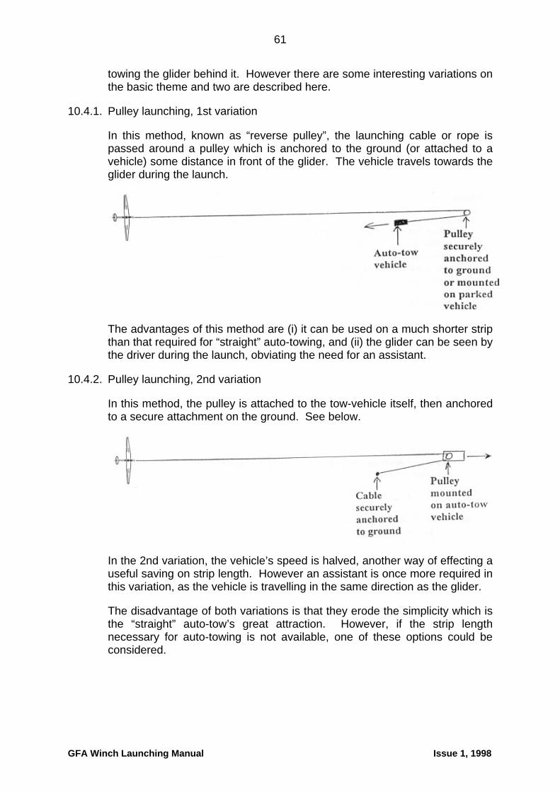
61
towing the glider behind it. However there are some interesting variations on the basic theme and two are described here.
10.4.1. Pulley launching, 1st variation
In this method, known as “reverse pulley”, the launching cable or rope is passed around a pulley which is anchored to the ground (or attached to a vehicle) some distance in front of the glider. The vehicle travels towards the glider during the launch.
The advantages of this method are (i) it can be used on a much shorter strip than that required for “straight” auto-towing, and (ii) the glider can be seen by the driver during the launch, obviating the need for an assistant.
10.4.2. Pulley launching, 2nd variation
In this method, the pulley is attached to the tow-vehicle itself, then anchored to a secure attachment on the ground. See below.
In the 2nd variation, the vehicle’s speed is halved, another way of effecting a useful saving on strip length. However an assistant is once more required in this variation, as the vehicle is travelling in the same direction as the glider.
The disadvantage of both variations is that they erode the simplicity which is the “straight” auto-tow’s great attraction. However, if the strip length necessary for auto-towing is not available, one of these options could be considered.
GFA Winch Launching Manual Issue 1, 1998
62
10.5 Auto-tow safety
10.5.1. Pilot safety
Although it might be thought that the leisurely rate of acceleration of the auto-tow would result in accidents caused by low-speed loss of control in the critical stages near the ground, the record shows that such is not the case.
At the time of publication of this manual there is only one club in Australia still using auto-tow for launching (RAAF East Sale, Victoria), but there have been many more in past years. The record indicates that launch safety of all auto-tow operators over the last 20 years has been considerably better than that of winch clubs over the same period.
Although the exact reason for this is not easy to determine, it probably has a lot to do with the fact that auto-tow pilots are better than winch pilots at correctly managing the climb profile during the early stages of the launch. This is a matter of necessity, because the speed does not increase at such a rate as to encourage “kavalierstart” take-offs, but it is still to the credit of past and present auto-tow operators that the level of safety has remained so consistently high. Long may this continue.
Winch-launch clubs might ponder the difference in safety levels between auto-tow and winching and maybe learn something about management of flight profiles during the early stages of the launch, as well as taming any rapid-acceleration enthusiasts that might exist among the ranks of their winch-drivers.
10.5.2. Driver and ground-crew safety
Due to the absence of whirling machinery and high-speed wire entering a stationary device, the safety of drivers and ground-crew is much higher with auto-towing compared with winch-launching.
Protection must still be provided for drivers and operators, as the behaviour of spring-steel wire is unpredictable. It goes without saying that nobody should be permitted to ride on the vehicle outside the safety of the cab when a launch is in progress.
10.5.3. Overall safety
Because auto-towing lends itself so readily to the use of rope, which is much better behaved than wire, the safety of all persons involved in the operation is higher than with winch-launching (apart from the one club using rope on a winch).
As far as outsiders are concerned, their safety is enhanced if rope is used. Being non-ferrous, it is much safer if accidentally dropped over a powerline. However, whatever material is used for auto-towing, the same precautions against dropping it outside the airfield must be observed as for winch-launching, in the interests of protecting innocent bystanders who are not
GFA Winch Launching Manual Issue 1, 1998

GFA Winch Launching Manual Issue 1, 1998
63
involved in our sport and who do not wish to be involved via the medium of a hospital visit or, worse, a funeral.