wind driven well pump team 1 - pennsylvania state university
TRANSCRIPT

Wind Driven Well Pump Team 1
Patrick McBride
Brian Cherewka
Anna George
Abdulaziz Zainal
Hunter Most
The Pennsylvania State University - ENGR 493 April 27, 2015

Wind Driven Well Pump Team 1: Final Report
1
Executive Summary The goal of this project is to assist developing communities in Africa with their
growing concern for the lack of their usable water. Our solution to this problem is
creating a wind turbine that will generate energy to power a well pump in order to acquire
water from their underground wells. With this, we will be harnessing the wind’s power
by transforming rotational energy of the turbine to the translational/linear energy of the
well pump. The gearbox system of this device is where such a transformation will occur,
and this is where the focus of our project lies.
Looking into the options for the gearbox system, our team debated over electrical
and mechanical power. Extensive research led us to conclude in choosing a mechanical-
powered gearbox system for the well pump, understanding that maintaining an electric
well pump would be difficult in the given conditions and climate of our clients.
After ruling out the electric method of power, our team heavily researched various
mechanical routes for the well pump. This led us to develop designs for the gearbox
system. Our ideas led us to create three unique designs, which we compared by
measuring the performance of each design with regard to a series of weighted priorities.
The priorities used to make the decision were efficiency, simplicity, sustainability,
maintenance, and cost.
Following our designs, we were able to construct a prototype of the gearbox
system, based on the third design. The design features a box that encloses the end of the
drive shaft (moving rotationally from the wind), which is connected through a series of
gears to a lever pump moving in a linear fashion. This lever arm connects to the pump,
thus successfully transforming the initial rotational energy into linear energy. After
building the prototype, the team was able to test the gearbox for its proof of concept and
power output performance.
Wind Driven Well Pump Team 1: Final Report
2
Table of Contents
1. Introduction ------------------------------------------- 3 1.1 Our Purpose………………………………………....…3
1.2 Client Needs ……………………………...………….…3 1.3 Background Information…………………..…….…….3 1.3.1 Wind Power History………………….4
1.3.2 The Vertical Axis Wind Turbine………4 1.3.3 The Horizontal Axis Wind Turbine……4 1.3.4 Wind Power Theory Basics……………5 1.3.5 Water pumping background…………..5 1.3.6 Piston Pump………………………….6
2. Team Collaboration ---------------------------------- 7 2.1 Our Team……………………………………………..…8 2.2 The Capstone Team…………………………………..…8 2.3 Division of Roles…………………………………………8
3. Design Process ---------------------------------------- 9 3.1 Design Iteration 1…………………………………..…9 3.2 Design Iteration 2……………………………………10 3.3 Design Iteration 3………………………...………….11
4. Decision Making Process -------------------------- 13 5. Building Process ------------------------------------- 14
5.1 Stage 1: Building the Gear Hub……………………14 5.2 Stage 2: Installing the Gears…………………...…...14
6. Building Challenges -------------------------------- 15 7. Results ------------------------------------------------- 16 8. Conclusion ------------------------------------------- 18 9. Further Areas of Interest ------------------------- 18
9.1 Efficiency……………………………………………18 9.2 Simplistic build…………………………..…………18 9.3 Build Changes………………………………….…...18
10. Appendix ---------------------------------------------19 11. References ------------------------------------------- 25
Wind Driven Well Pump Team 1: Final Report
3
1. Introduction
1.1. Our Purpose In our collaborative effort, our team’s mission is as follows: “The Wind Driven Well Pump Team 1 will assist in the creation of a prototype for
a wind-powered turbine to be utilized by a well pump.” As a team, our core ideologies are subjected into three categories: research,
quality, and opportunity. We value providing cutting edge research that will not only give an excellent background of our objectives, but also give the best solution to our clients. This guarantees the best quality and efficiency for acquiring water in the wells. Our collaboration with the capstone team (also referred to as the 496 team) will offer new opportunities to obtain useable water for the communities in Africa.
Our values can be summed up in the following statement: “To enhance the lives of citizens in developing countries by making water more
attainable.” Here, our values envelope into sustainability and inexpensive technology. By
focusing on sustainability, we wish to follow eco-friendly actions and utilize green materials. This will reduce harm done towards the environment. Inexpensive technology is equally important due to the fact of making the water more attainable for those people in these developing communities. 1.2. Client Needs
Our team is asked to design a mechanical gearbox system that will connect the water pump and the wind turbine. This system will convert the rotational energy of the wind turbine into translational energy that will pump water out of the underground wells. The upper end will be attached to an axial rod of the turbine, while the lower part will be attached to the handle of a siphon well pump. The turbine and pump system are going to be designed by the Capstone team. Preliminarily, the whole system needs to produce 50 Watts of power in order to pump the water at five GPM.
1.3. Background Information
Many developing communities in Africa struggle to obtain safe, natural water from their underground wells. These communities are lacking one of the most essential elements for human life, and are negatively affecting their daily activities and health.
Our team is tasked to solve this issue. We were asked to find a solution in creating
a device to allow this underground water to be more attainable. We are challenged to create a well pump that is driven by wind power. This is an environmental approach in order to solve the task. Essentially, we are combining a wind turbine and well pump into one sound, functional device for these developing communities. We will be designing

Wind Driven Well Pump Team 1: Final Report
4
and building a prototype for a system to convert the rotational energy of a turbine into the linear motion needed to operate a water pump. 1.3.1. Wind Power History
Harnessing wind to further the advancement of mankind dates back to as far as 5000 BC, when wind was first utilized to propel boats across the Nile. As time went on, different uses of wind began to emerge. In the Middle East, they used wind turbines to power a system that grinded grain. There are even records of the Persians harnessing the wind in order to pump water as far back as 200 BC.1 If you fast-forward to 1970, wind turbines are beginning to be used for the generation of electricity. 40 years later, in 2010, there are enough wind turbines in the US to power 15 million homes per year.8
1 Figure 1.3.1. Early Persian Wind Turbine
1.3.2. The Vertical Axis Wind Turbine
The vertical axis wind turbines, or VAWT, are known for their ability to harness wind from all directions. They also are quitter in comparison to horizontal axis turbines. However, not all VAWTs are able to self-start, so they must rely on a motor to ensure they start.
There are two main types of VAWTs: the Savonius and the Darrieus. The
Darrieus, sometimes referred to as the “eggbeater” was invented in 1931 bye Georges Darrieus. The Savonius turbine was invented by Finnish Engineer Sigurd Johannes Savonius. The main difference between the two is that the Darrieus turbine relies on lift force from the pressure differential caused by the wind, while the Savonius turbine relies on drag force from the wind.3
1.3.3. The Horizontal Axis Wind Turbine
The HAWTs are generally more efficient at converting wind power into energy. They also have the ability to generate power at lower wind speeds. They have to been tested to work optimally at wind speeds of 5m/s, but average annual speeds of 3-4m/s are adequate for water pumping. For these reasons, the HAWT design was selected for our wind turbine.4

Wind Driven Well Pump Team 1: Final Report
5
One of the disadvantages of the HAWTs is that they rely on the direction of the wind. They must be placed perpendicular to the direction of the wind or have the ability to rotate. This is accomplished by connecting a wind vane to a yaw drive to rotate the turbine to face perpendicular to the wind.4 If they do not have the ability to rotate, they will only capture 21% of the energy available.5
Figure 1.3.3. Basic Diagram of a HAWT
1.3.4. Wind Power Theory Basics The equation for the maximum amount of power produced by wind be expressed as pWind=.5ρAV3. In this equation, ρ is the density of air, A is the area swept by the blades, and V is the speed of the wind.6 However, no design can operate at 100% efficiency. The maximum efficiency is limited to 59% according to the Betz law. Therefore, a power coefficient of Cp must be added into the equation, making the final equation pwind=.5 ρAV3Cp. The coefficient varies for each design and as it comes down to how efficiently, the system converts the energy. The average coefficient ranges from .35-.45.6 1.3.5. Water pumping background There are two main categories of pumps in regards to small water systems. There are dynamic pumps and displacement pumps. Dynamic systems add energy into the water at constant rates and water pumps out in no volume; while, displacement pumps add energy periodically into the water with set volumes of water pumped out.7

Wind Driven Well Pump Team 1: Final Report
6
1.3.6. Piston Pump The piston pump we bought was the model HWP-E HandyWellPump. This pump
develops 50-60psi and can generate 24-28 fl. oz. per stroke.9
Figure 1.3.6. The HWP-E Model Pump

Wind Driven Well Pump Team 1: Final Report
7
2. Team Collaboration
Table 2.1. ENGR 493 Team
Name Year Major Contribution
Hunter Most
Senior Industrial Engineering
• Strategic Planning
• Construction • Documentation
Abdulaziz Zainal
Junior Petroleum & Natural Gas Engineering
• Construction • Research • Documentation
Patrick McBride
Sophomore Mechanical Engineering
• Design • Construction • Documentation
Brian Cherewka
Freshman Industrial Engineering
• Research • Documentation • Design
Anna George
Freshman Civil Engineering
• Strategic Planning
• Documentation • Research

Wind Driven Well Pump Team 1: Final Report
8
2.1. ENGR 493 Team Our team consisted of five members with various backgrounds. This variation lends itself nicely to a division of labor in which each task was managed by a subgroup. Hunter and Anna focused on strategic planning and helped to keep the team on track with progress. With the project schedule organized, the team began extensive research. The major contributing research was completed by Brian, Anna, and Abdulaziz. The design effort was spearheaded by Patrick, with contributions from Hunter and Abdulaziz. After the design and materials decisions were made, Aziz and Hunter began the implementation process construction. Patrick was also vital to the construction process. Each member was additional fundamental in the documentation of each respective section, as required by updates, plans, and presentations. 2.2. Capstone Team Our team worked collaboratively with another team of engineers working on a capstone project. The capstone team was made up of three seniors in the college of engineering who had a strong background in chemical engineering. 2.3. Division of Roles Though both teams worked collaboratively on the entire project, there was a specific division of labor. After it was decided that the pump for the prototype would be manual and purchased, the teams split up the remaining work. The capstone team focused on the creation of the turbine itself, the ENGR 493 team focused on creating a system that converted the rotational energy caused by the turbine into linear energy to power the pump.
Wind Driven Well Pump Team 1: Final Report
9
3. Design Process
Through an iterative design process, the three main ideas created all have similar aspects but overall different designs. The main goal with this project was to pump water out of a well by harnessing the power of the wind through a wind turbine. Most wind turbines achieve this action by using an alternator to convert wind power into electricity and then use this electricity to operate an electric water pump. However, there are limitations regarding the available use of electricity and having to use a mechanical water pump. These offered many difficult design challenges and building constraints. Each iteration of the design offered a solution, which was measured against the set constraints. With extensive research, the attempt to improve each design guided the creation of the next.
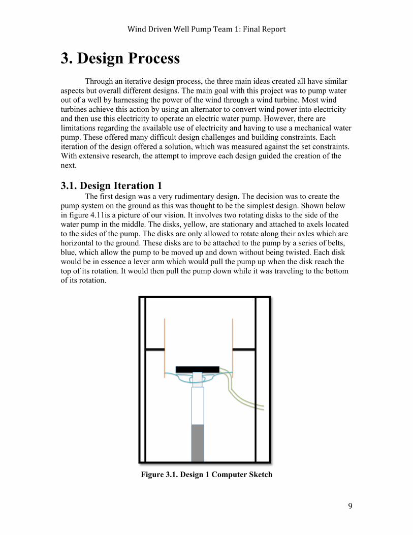
3.1. Design Iteration 1 The first design was a very rudimentary design. The decision was to create the pump system on the ground as this was thought to be the simplest design. Shown below in figure 4.11is a picture of our vision. It involves two rotating disks to the side of the water pump in the middle. The disks, yellow, are stationary and attached to axels located to the sides of the pump. The disks are only allowed to rotate along their axles which are horizontal to the ground. These disks are to be attached to the pump by a series of belts, blue, which allow the pump to be moved up and down without being twisted. Each disk would be in essence a lever arm which would pull the pump up when the disk reach the top of its rotation. It would then pull the pump down while it was traveling to the bottom of its rotation.
Figure 3.1. Design 1 Computer Sketch
Wind Driven Well Pump Team 1: Final Report
10
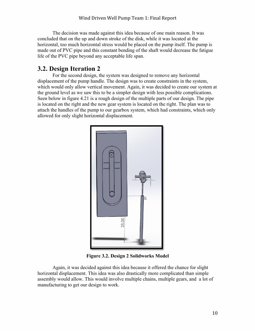
The decision was made against this idea because of one main reason. It was concluded that on the up and down stroke of the disk, while it was located at the horizontal, too much horizontal stress would be placed on the pump itself. The pump is made out of PVC pipe and this constant bending of the shaft would decrease the fatigue life of the PVC pipe beyond any acceptable life span. 3.2. Design Iteration 2 For the second design, the system was designed to remove any horizontal displacement of the pump handle. The design was to create constraints in the system, which would only allow vertical movement. Again, it was decided to create our system at the ground level as we saw this to be a simpler design with less possible complications. Seen below in figure 4.21 is a rough design of the multiple parts of our design. The pipe is located on the right and the new gear system is located on the right. The plan was to attach the handles of the pump to our gearbox system, which had constraints, which only allowed for only slight horizontal displacement.
Figure 3.2. Design 2 Solidworks Model
Again, it was decided against this idea because it offered the chance for slight
horizontal displacement. This idea was also drastically more complicated than simple assembly would allow. This would involve multiple chains, multiple gears, and a lot of manufacturing to get our design to work.

Wind Driven Well Pump Team 1: Final Report
11
3.3. Design Iteration 3 The final design is what was decided to put into practice and prototype. This design varies from the previous two designs because it is located at the top of the turbine instead of on the ground. This design would utilize two chains on a gear train, which would give the correct speed and torque required to pump water.
Figure 3.3.1. Front View
Figure 3.3.2. Rear View

Wind Driven Well Pump Team 1: Final Report
12
Figure 3.3.3. Front Close-Up (Supports)
Figure 3.3.4. Bottom View (Turntable)

Wind Driven Well Pump Team 1: Final Report
13
Figure 3.3.1. shows the front of the design. The turbine blade shaft is coming in from the left and enters the gearbox system. It has a sprocket on the end of it, which is connected by chain to the rest of the system. Seen in Figure 3.3.2. is the back of the gearbox system. On the right, you can see the part of the system, which moves the pump up and down. It is a system of two lever arms that cause a torque, which moves the pump in a vertical motion. Figure 3.3.3.is an up-close view of the front of the gearbox system. Figure 3.3.4. shows the bottom of our gearbox system. Seen in the picture is a turntable which will allows both the gearbox system and the turbine blades to always face the wind.
This design also had many challenges associated with it. First, in order to have an axle that rotates with little resistance, there was a need to make sure that they were perfectly aligned. Another design challenge was going to be creating lever arms strong enough to not bend or break under the stress required to operate the pump. The final challenge was how this was to be designed resistant enough to be placed in a harsh environment while also being light enough to rest on top of a metal structure of the wind turbine.
4. Decision Making Process In order to choose the most optimal design, each design was ranked on a
weighted-priority scale. The priorities used to make the decision were efficiency, simplicity, sustainability, maintenance, and cost. Each priority was assigned a weight that represents the comparative importance to the overall success of the project. Following the weight assignment, each design was scored on its performance with regard to each of the priorities. The scores (1-5) were then multiplied by the respective weight, to receive a weighted score. The total weighted scores for each design were calculated and compared resulting in a 2.65, 2.0, and 3.4 respectively. This data supports the selection of Design 3 for implementation.
Table 4.1. Weighted Priority Scoring

Wind Driven Well Pump Team 1: Final Report
14
5. Building Process
We started our building process by choosing the right materials that will work perfectly with our prototype design. As a result, we ended by choosing MDF plywood, PVC pipes and 2x4” whitewood stud as a main materials. nevertheless, we decided to breakdown the building process into two stages. 5.1. Stage 1: Building the Gear Hub
1. Using the automatic saw, cut three pieces of the MDF plywood in order to create the base, front and the back face of the gear hub.
2. Cut 3 foot long pieces from the whitewood stud to create the drive shaft support and the side walls of the gear hub.
3. Drill 3 ¾” holes in both the front face of the gear hub and a hole the drive shaft supporter in order to insert the drive shaft through the hub.
4. To create the gear hub, place the base piece of plywood (previously cut) horizontally to start creating the gear hub. Place the front and the back faces vertically on the base and connect the three plywood pieces by L-brackets.
5. Connect the drive shaft supporter to the base using L-brackets 6. Assemble the Head bar (H-bar) by cutting small pieces from the PVC pipe to
create elbow joints that connect the four 45⁰ elbows with the 2 PVC pipes. 7. Enclose the gear hub by placing the two stud pieces left on the sides and connect
them to the base with L-brackets. This creates the sidewalls of the hub. 8. Cut a piece from the plywood to create a lid for the hub. 9. Drill 2” holes in the lid and in the base of the hub.
5.2. Stage 2: Installing the Gears
1. Drill six holes with ⅝” bearings to allow a perfect movement for the driving shafts
2. Insert the driving shaft we have and plug the sprockets to the shafts. To prevent the shafts from sliding, lock them with shaft collars.
3. Place one small sprocket on the end of the turbine drive shaft. Also, place a large sprocket at the front of the right shaft as well as a small sprocket at the back of it. Place a small sprocket at the back of the left shaft as well as a large sprocket at the front of it.
4. Make a lever arm out of plywood and we attach it to the back of the left shaft. Attach it to the drive bar restraint.
5. Use the chain breaker tool to break the chain so that they fit the gears at a perfect length.
6. With these chains, place them around each of the sprockets and re-attach the chains by using roller chain connectors.

Wind Driven Well Pump Team 1: Final Report
15
6. Building Challenges The most critical challenges we faced during the building process was the lack of
time, as the project itself needed a lot of attention with limited time granted. In addition, the equipment and tools were not efficient enough to provide the upmost design of our project, as our model proportions were relatively oversized for using the tools in the workshop, which as a result delayed the building process. One of the remarkable challenges we faced in the building process was drilling holes with the specific sizes needed for the PVC pipes to run the gear hub as well as the drive shafts holes, the reason why was because almost all the tools we need for drilling the required holes, were either broken or unavailable.
In addition, the fact that we only have four hours in the weekdays to use the workshop as it opens from 7pm until 11pm was a major problem we faced by itself, which made the building process very slow. Another challenge we faced during the building process was due to the fact that we were collaborating with another team to build the complete wind turbine, as each team worked separately which made it hard for us to visualize the final design. However, as a team we were successful on working with what we had and provided the best alternative for our design.
Figure 6.1. Fitting MDF onto Drill Press
Wind Driven Well Pump Team 1: Final Report
16
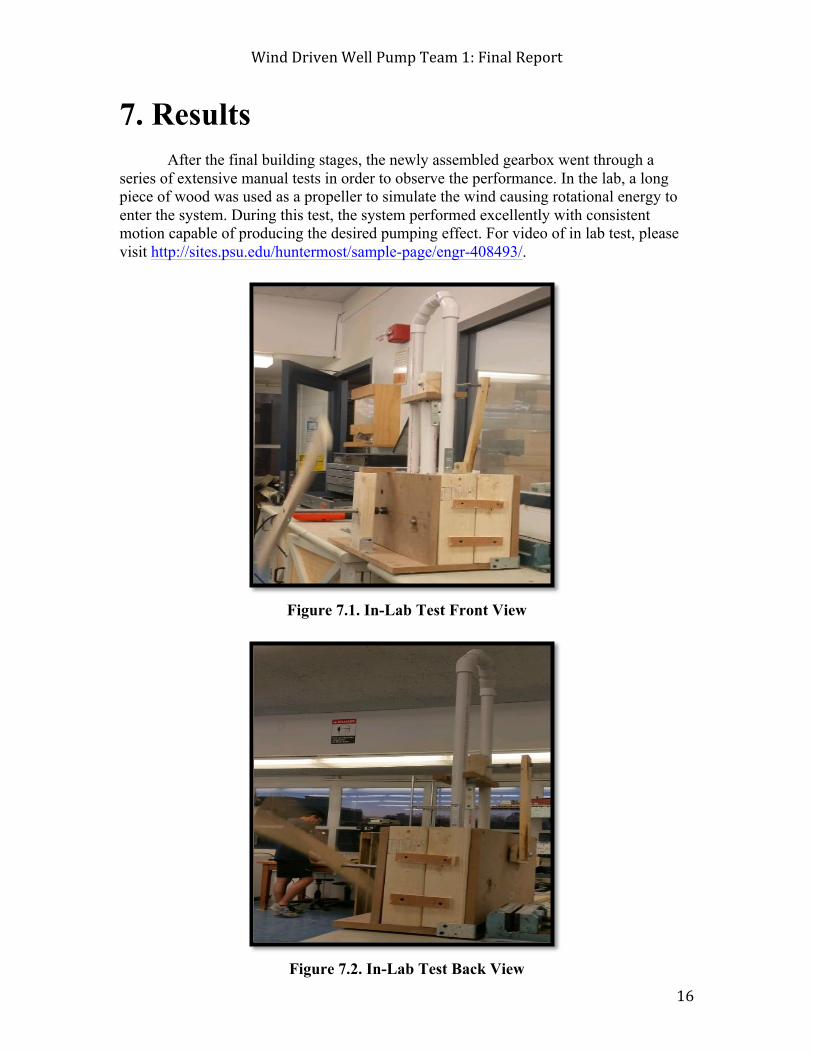
7. Results After the final building stages, the newly assembled gearbox went through a
series of extensive manual tests in order to observe the performance. In the lab, a long piece of wood was used as a propeller to simulate the wind causing rotational energy to enter the system. During this test, the system performed excellently with consistent motion capable of producing the desired pumping effect. For video of in lab test, please visit http://sites.psu.edu/huntermost/sample-page/engr-408493/.
Figure 7.1. In-Lab Test Front View
Figure 7.2. In-Lab Test Back View

Wind Driven Well Pump Team 1: Final Report
17
In the end, the prototype worked and excellently demonstrated proof of the design concept. After the completion of the gearbox, the turbine system was assembled to test the final product. Though an imperfect model, the final system was shown to spin with wind and convert that energy to a pumping motion.
Figure 7.3. Full System Test (Gearbox, Support System, Pump, Propeller Blades)

Wind Driven Well Pump Team 1: Final Report
18
9. Conclusion This project required tangible skill in both engineering and leadership. For many
the group members, this was the first such project encountered. Working in a team for an entire semester can create extreme leadership challenges, which must be overcome in order to have a successfully engineered final result. Through an immense amount of cooperation and collaboration, the team was able to overcome such challenges as ineffective communication and division of labor. This success made it possible for the creation of a final design that was feasible for a working prototype.
10. Further Areas of Interest 10.1. Efficiency As we spent the semester trying to design and build the gearbox for this turbine, most of our effort was put towards producing a model that was simply functional. We didn’t have any previous designs to go tweak for our benefit, so everything was very basic. Since there is now a working model in place for future groups, they have the ability to make small adjustments to continue to increase the efficiency. 10.2. Simplistic build Due to the limitations of our budget and the limited resources we had in small wood-workshop we had in Hammond, our design had to be extremely simple. As future groups are able to take advantage of the equipment in the learning factory and other workshops, the building process can be more exact to improve efficiency. 10.3. Build Changes The future groups working on this project can also work on the aesthetic aspect of the gearbox. Again, most of our effort went into making sure our design was simply functional; we were not able to spend as much time making the gearbox visually appealing.

Wind Driven Well Pump Team 1: Final Report
19
10. Appendix
Gearbox System Construction Manual
Patrick McBride Brian Cherewka
Anna George Abdulaziz Zainal
Hunter Most
Wind Driven Well Pump Team 1: Final Report
20
Introduction Our Purpose
In our collaborative effort, our team’s mission is as follows: “The Wind Driven Well Pump Team 1 will assist in the creation of a prototype for
a wind-powered turbine to be utilized by a well pump.” As a team, our core ideologies are subjected into three categories: research,
quality, and opportunity. We value providing cutting edge research that will not only give an excellent background of our objectives, but also give the best solution to our clients. This guarantees the best quality and efficiency for acquiring water in the wells. Our collaboration with the capstone team (also referred to as the 496 team) will offer new opportunities to obtain useable water for the communities in Africa.
Our values can be summed up in the following statement: “To enhance the lives of citizens in developing countries by making water more
attainable.” Client Needs
Our team is asked to design a mechanical gearbox system that will connect the water pump and the wind turbine. This system will convert the rotational energy of the wind turbine into translational energy that will pump water out of the underground wells. The upper end will be attached to an axial rod of the turbine, while the lower part will be attached to the handle of a siphon well pump. The turbine and pump system are going to be designed by the Capstone team. Preliminarily, the whole system needs to produce 50 Watts of power in order to pump the water at five GPM.
CAUTION
Please be aware of the use of POWER TOOLS, SHARP TOOLS, as well as HEAVY LIFTING.

Wind Driven Well Pump Team 1: Final Report
21
Materials Stage 1 Materials:
Stage 2 Materials:
2x4” wood
¾” MDF Plywood
PVC
Drive Shaft
Sprockets
Rotating Table

Wind Driven Well Pump Team 1: Final Report
22
Stage 1: Building the Gear Hub
1. Using the automatic saw, cut three pieces of the MDF plywood in order to create the base, front and the back face of the gear hub.
2. Cut 3 foot long pieces from the whitewood stud to create the drive shaft support and the side walls of the gear hub.
3. Drill 3 ¾” holes in both the front face of the gear hub and a hole the drive shaft supporter in order to insert the drive shaft through the hub.
4. To create the gear hub, place the base piece of plywood (previously cut) horizontally to start creating the gear hub. Place the front and the back faces vertically on the base and connect the three plywood pieces by L-brackets.
5. Connect the drive shaft supporter to the base using L-brackets. (See Figure 1 from this point)
6. Assemble the Head bar (H-bar) by cutting small pieces from the PVC pipe to create elbow joints that connect the four 45⁰ elbows with the 2 PVC pipes. (See Figure 2)
7. Enclose the gear hub by placing the two stud pieces left on the sides and connect them to the base with L-brackets. This creates the sidewalls of the hub. (See Figure 3)
8. Cut a piece from the plywood to create a lid for the hub.
9. Drill 2” holes in the lid and in the base of the hub.
Wind Driven Well Pump Team 1: Final Report
23
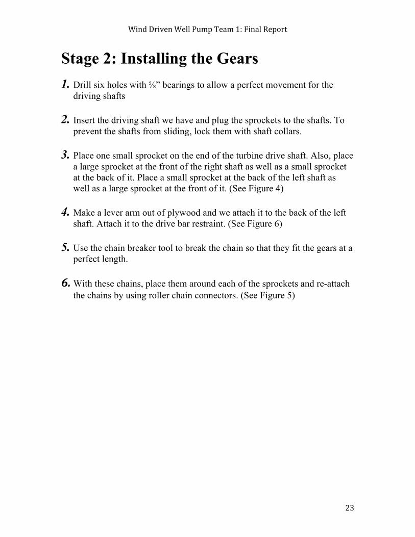
Stage 2: Installing the Gears
1. Drill six holes with ⅝” bearings to allow a perfect movement for the driving shafts
2. Insert the driving shaft we have and plug the sprockets to the shafts. To prevent the shafts from sliding, lock them with shaft collars.
3. Place one small sprocket on the end of the turbine drive shaft. Also, place a large sprocket at the front of the right shaft as well as a small sprocket at the back of it. Place a small sprocket at the back of the left shaft as well as a large sprocket at the front of it. (See Figure 4)
4. Make a lever arm out of plywood and we attach it to the back of the left shaft. Attach it to the drive bar restraint. (See Figure 6)
5. Use the chain breaker tool to break the chain so that they fit the gears at a perfect length.
6. With these chains, place them around each of the sprockets and re-attach the chains by using roller chain connectors. (See Figure 5)

Wind Driven Well Pump Team 1: Final Report
24
Visual of Construction
Figure 4
Figure 1 Figure 2
Figure 3
Figure 5 Figure 6

Wind Driven Well Pump Team 1: Final Report
25
11. References
1. "History Of Wind Energy." Wind Energy Foundation, n.d. Web. 25 Apr. 2015.
<http://www.windenergyfoundation.org/about-wind-energy/history>.
2. "Horizontal Wind Axis Turbine." Turbineinfo.com. Turbine Info, 05 July 2011. Web.
25 Apr. 2015.
3. "HWP-E." Handywellpump.com. Handy Well Pemps, n.d. Web. 25 Apr. 2015.
4. "Introduction to Pumping Systems." Journal (Water Pollution Control Federation)
59.3, Part I (1987): 162-70. Dec.alaska.gov. Alaska Department of Environmental
Conservation. Web. 25 Apr. 2015.
5. Sutherland, Herbert J. "A Retrospective of VAWT Technology." American Libraries
41.1/2 (2010): 9-20. Energy.gov. Sandia National Labraories. Web.
6. "The Development of Wind Power." For the Wind. N.p., 08 May 2012. Web. 25 Apr.
2015.
7. "Wind Turbine Power Calculations." Raeng.org. The Royal Academy Of
Engineering, n.d. Web. 25 Apr. 2015.
8. "Wind Farm Growth Through The Years." Energy.gov. US Deprtment of Energy, n.d.
Web. 25 Apr. 2015.
9. Wortman, Andrze J. Introduction to Wind Turbine Engineering. Boston: Butterworth,
1983. Print.