wind turbine aerodynamics research needs assessment/67531/metadc... · wind turbine aerodynamics...
TRANSCRIPT
DoE/ER/30075-Hl
qq,~(’y]$[ j“1
WIND TURBINE AERODYNAMICSRESEARCH NEEDS ASSESSMENT
January 1986
Prepared by:F. S. Stoddard, Principal Investigator
B. K. Porter, Project Coordinator
Washington Consulting GroupWashington, D.C. 20006
Contract No. DE-ACOI -85 ER30075
U.S. Department of EnergyOffice of Energy ResearchOffice of Program Analysis

Cover photograph furnished courtesy ofCermak/Peterka & Associates Inc.,Fort Collins, Colorado, March 1986.

DISCLAIMER
This report was prepared as an account of work sponsoredby an agency of the United States Government. Neitherthe United States Government nor any agency thereof, norany of their employees, make any warranty, express orimplied, or assumes any legal liability or responsibility forthe accuracy, completeness, or usefulness of anyinformation, apparatus, product, or process disclosed, orrepresents that its use would not infringe privately ownedrights. Reference herein to any specific commercialproduct, process, or service by trade name, trademark,manufacturer, or otherwise does not necessarily constituteor imply its endorsement, recommendation, or favoring bythe United States Government or any agency thereof. Theviews and opinions of authors expressed herein do notnecessarily state or refiect those of the United StatesGovernment or any agency thereof.

DISCLAIMER
Portions of this document may be illegiblein electronic image products. Images are
produced from the best avaiiable originaldocument.

TABLE OF CONTENTS
Executive Summary . . . . . . . . . . . . . . . . . . . . . . . . . . . . ...0 .. 0.0..= . . . iv
List of Figures . . . . . . . . . . . . . . . . . . . . . . . . . . . . . . . . . . . . . . . . . . . . . . . xi
Introduction...
. . . . . . . . . . . . . . . . . . . . . . . . . . . . . . . . . . . . . . . . . . . . . . . . XIII
CHAPTERS
1.
2.
3.
4.
5.
6.
7.
8.
Technical Assessment Panel and Procedure . . . . . . . . . . . . . . . . . . . . . . . . .
Research Needs Assessment Methodology . . . . . . . . . . . . . . . . . . ...= . . . . .
Wind Turbine Aerodynamic Study Areas . . . . . . . . . . . . . . . . . . . . . . . . . .
Airfoil andRotor Behavior . . . . . . . . . . . . . . . . . . . . . . . . . . . . . . . . . .Steady Aerodynamics . . . . . . . . . . . . . . . . . . . . . . . . . . . . . . . . . .Unsteady Aerodynamics . . . . . . . . . . . . . . . . . . . . . . . . . . . . . . . . . .
Inflow Models . . . . . . . . . . . . . . . . . . . . . . . . . . . . . . . . .* .*.... . ..-Interface Topics . . . . . . . . . . . . . . . . . . . . . . . . . . . . . . . . . . ...*... . .
Aeroelasticity . . . . . . . . . . . . . . . . . . . . . . . . . . . . . . . . . . . . . . . . .Control Systems . . . . . . . . . . . . . . . . ● . . ...*. . . . . . . . . . . . . . . . .Shutdown Systems . . . . . . . . . . . . . . . . . . . . . . . . . . . . . . . . . . . . .Interference . . . . . . . . . . . . . . . . . . . . . . . . . . . . . . . . . . . . . . . . . .
Wind Turbine Aerodynamic Research Needs and Priorities . . . . . . . . . . . .=..
Specific Aerodynamic Research Needs by Priority . . . . . . . . . . . . . . . . . . . .Unsteady Aerodynamics . . . . . . . . . . . . . . . . . . . . . . . . . . . . . . . . . .Inflow Models . . . . . . . . . . . . . . . . . . . . . . . . . . . . . . . . . . . . . . . .Interface Topics . . . . . . . . . . . . . . . . . ...* . . . . . . . . . . . . . . . . . .Steady Aerodynamics . . . . . . . . . . . . . . . . . . . . . . . . . . . . . . . . . . . .
The Need forBasic Research. . . . . . . . . . . . . . . . . . . . . . . . . . . . . . . . . . .
The Need for Aerometeorology . . . . . . . . . . . . . . . . . . . . . . . . ...* . . . . .
Applications Studies . . . . . . . . . . . . . . . . . . . . . . . . . . . . . . . . . . . . . . . . .
Noise . . . . . . . . . . . . . . . . . . . . . . . . . . . . ...* . . . . . . . . . . ..*...**Rotor Size, Productivity, and Economy of Scale . . . . . . . . . . . . . . . . . . . . . .Variable Speed Rotors . . . . . . . . . . . . . . . . . . . . . . ...=. .- ==...=. ● **Advanced Concepts . . . . . . . . . . . . . . . . . . . . . . . . . . . . . . . . . . . . . . . . .New Descriptors . . . . . . . . . . . . . . . . . . . . . . . . . . . . . . . . . . . . . . . . . . . .
Recommended DOE Wind Turbine Unsteady Aerodynamics R&DProgram . . . . . . . . . . . . . . . . . . . . . . ...*.. . . . . . . . . ● ..****. ● . . .
List of References . . . . . . . . . . . . . . . . . . . . . . . . . . . . . . . . . . . . . . . . . . . .
-ii-
1
4
9
99
11
202222223030
31
3333394650
54
56
60
6064707176
78
83
—
APPENDICES
1. Technical Assessment Panel and Procedures . . . . . . . . . . . . . . . . . . . . . . . . . . . . . . .
2.
3.
4.
A Tutoriak The Influence of Aerodynamics onWind Turbine Design . . . . . . . . . . . . . . . . . . . . . . . . . . . . . . . . . . . . . . . . . . . . . . . .
Rotor Characteristics . . . . . . . . . . . . . . . . . . . . . . . . . . . . . . . . . . . . . . . . . . . . . . . . .Rotor Aerodynamic Design . . . . . . . . . . . . . . . . . . . . . . . . . . . . . . . . . . . . . . . . . . . .Wind Turbine Comparison . . . . . . . . . . . . . . . . . . . . . . . . . . . . . . . . . . . . . . . . . . . .
Summary of Generic Design Approaches . . . . . . . . . . . . . . . . . . . . . . . . . . . . . . . . .
Wind Turbine Industry Representativesand Sites Visited, July 1985 . . . . . . . . . . . . . . . . . . . ...4>.... . . . . . . . . . . . . . . . .
89
99
99100109
116
125
. . .-111-

EXECUTIVE SUMMARY
Wind energy is a potentiallyviable technology, but one that nowneeds carefully planned research inorder that pressing design problemscan be solved. Wind turbine designtools must be improved for theadequate prediction of performanceand reliability. This is due in partto the severe environmental demandsfor wind energy systems, and inpart to a lack of understanding ofwind turbine aerodynamics.
TECHNICAL ASSESSMENT PANELAND PROCEDURE
The Wind Turbine AerodynamicsTechnical Assessment Panel (“Panel”)was formed by the Washington Consult-ing Group under the sponsorship ofthe Office of Energy Research ofthe U. S. Department of Energy,and was directed to define the highestpriority research needs relating tothe aerodynamics of wind turbines.
In addition to its own meetingsand deliberations, the Panel attendeda DOE-sponsored seminar on theaerodynamics of wind turbines atSandia National Laboratory in Albu-querque, NM, in March 1985, abriefing by wind turbine industryrepresentatives in Oakland, Cali-fornia, in July 1985, and conductedan inspection of a number of windfarm installations at Altamont Passand the Boeing/PGE Mod-II windturbine in Fairfield, California.The Panel also reviewed a substantialnumber of technical reports document-ing the research on the aerodynamicsof wind turbines.
The Panel’s goal was to developa prioritized list of wind turbine
aerodynamic research needs andopportunities which could be usedby the Department of Energy programmanagement team in detailing theDOE Five-Year Wind Turbine ResearchPlan. The focus of the Assessmentwas the basic science of aerodynamicsas applied to wind turbines, includ-ing all relevant phenomena, suchas turbulence, dynamic stall, three-dimensional effects, viscosity,wake geometry, and others whichinfluence aerodynamic understandingand design.
The study was restricted towind turbines that provide electricalenergy compatible with the utilitygrid, and included both horizontalaxis wind turbines (HAWT) andvertical axis wind turbines (VAWT).Also, no economic constraints wereimposed on the design concepts orrecommendations since the focus ofthe investigation was purely scientific.
RESEARCH NEEDS ASSESSMENTMETHODOLOGY AND WIND TURBINEAERODYNAMICS STUDY AREAS
The Panel established a methodto identify the present researchneeds: first a hierarchy of aero-dynamic study areas relevant tothe engineering design of windturbines was established. Thestudy areas ranged from simple,steady-state, two-dimensional(2-D) airfoil studies, to the verycomplex stochastic representationof unsteady turbulence of thewind. Each of these was furtherbroken down into specific subcate-gories, developed in order of comp-lexity.
-iv-

The first category is the inter-action between the airflow and theairfoil. This includes steady aero-dynamics, on which most classicalaerodynamics and most presentdesign tools for wind turbines arebased, and unsteady aerodynamics,which is concerned with airfoil androtor behavior under time-varyingconditions.
Each concept was then discussedand evaluated for each aerodynamictopic, and a numerical researchopportunity priority was establishedfor each.
WIND TURBINE AEROD~JAMICRESEARCH NEEDS AND PRIORITIES
The second major aerodynamictopic is the inflow to the rotor,which consists ofi
wind speed and directionfluctuations,
terrain-induced fluctuations,and
interference-inducedfluctuations,
all of which are unsteady.
In the third and last categoryof aerodynamic study are interfacetopics, for which the aerodynamicsplays a major role through theunsteady airloading, but whichdepend also on other disciplines.These are aeroelasticity, controlsystems, shutdown systems, andinterference.
Next, having established a frame-work of topics for discussion, thePanel chose seven generic designapproaches for wind turbines whichare the most significant and in thePanel’s view, represent the bestpotential for improving the costand reliability of wind energy systems.
These were
o Stall controlo Pitch controlo Variable speed HAWTo Darrieus VAWTo Straight blade VAWTo High tip speed HAWTo Free Yaw HAWT
The highest priority research wasidentified as those topics whichare common to all design approaches,that cut across design and configu-ration boundaries, and will enhancethose approaches and others yetto be identified.
The Panel agreed that the followingthree subject areas and specificsubdiscipline are the highestpriority aerodynamic researchareas and opportunities for futuredevelopment of the wind-powerindustry
Unsteady Aerodynamics
Dynamic Stall Understanding--
Develop an understandingof the 2-D and 3-D hysteresiseffects of dynamic stall.
Testing Methodology for UnsteadyFlow--
Stimulate complex unsteadyflows in wind tunnel andtotal system (field) tests inorder to exploit dynamicstaIl effects.
Airfoil Development Studiesfor Unsteady Flow--
Initiate a design processwhich will yield airfoilsspecifically suited for unsteadyflow, and which considersthe significance ofi
-v-

o
00
000
dynamic stall repeat-ability and insen-sivityairfoil roughnessdelayed stall and softstall
performance and predictionrotor stability; andairfoil control devices.
Wind Inflow Models The Develop-ment of Aerometeorology
Establish a new study termedaerometeorology, which will attemptto develop realistic inflow modelsfor the assessment of unsteadyeffects, including the specificcases ofi
o
0
0
0
unsteady, uniform inflow- -or representation of theuniform gust front;unsteady nonuniform inflow--or representation of frozenturbulence;steady, nonuniform inflow--or representation of steadyinflow fronts; andstochastic inflow--or representation ofinflow in the frequency/wavenumber domain.
Interface Topics
Aeroelasticity --
Develop a methodology fordefining the unsteady airloads
. which must be included in thestructural dynamic models.
Control Systems- -
Investigate the performanceand reliability benefits to beobtained with external controlactions, such as ailerons, insteady and unsteady flow.
Wake Model Interference Develop-ment--
Develop and verify a modelfor the structure and decayof the unsteady wind tur-bine rotor wake.
Component Wake InterferenceDevelopment--
Develop and verify modelsfor the structure and decayof the unsteady wakes causedby turbine components suchas towers.
Shutdown (Emergency) Systems--
Develop an understandingof the behavior of airfoilsunder extreme conditions,and at very high angles ofattack, such as a movingaileron in separated flow.
In addition, further steady-stateaerodynamics studies should becontinued in order to provide asuitable data base for the aboveinvestigations and lend insightinto the new physical and mathe-matical models and design toolswhich must be used.
Steady Aerodynamics
Three-Dimensional Flow--
Assess the degree of 3-Dor spanwise flow whichoccurs under typical conditions,and relate that to the inflowand turbine wake geometry.
Wake Modeling--
Develop and verify a modelof the turbine vortex wakegeometry suitable for perfor-mance and stability studies.,.
-vi-

Effect of Roughness in SteadyState--
Develop an understanding ofenvironmentally-induced airfoilsurface roughness on airfoiltransition and separation insteady flow.
Airfoil Mechanisms--
Investigate the effect ofairfoil mechanisms, such asvortex generators, on delayingturbine rotor stall andseparation,
Two-Dimensional Airfoil Develop-ment--
Develop a verified methodologyfor tailored wind turbineairfoil design in steady stateto establish a database forfuture unsteady airfoil design.
Testing Methodology for SteadyFlow- -
Continue steady-state windturbine testing in wind tunnelsand in the field, to acquirelong-term performance dataand to investigate the benefitsof new airfoils.
THE NEEDS FOR BASIC RESEARCHAND AEROMETEOROLOGY
The Panel determined that the majorwork should be in unsteady aerody-namics and rotor inflow and recom-mends that the emphasis be onbasic research rather than on appliedresearch. The basic research whichis called for here must establish atechnology base strong enough sothat design decisions can be madewith confidence and not by trialand error as is often the case now.The Panel believes that very sign-ificant improvement in the perfor-
mance, reliability, and economics ofwind turbines is possible given aproper unsteady aerodynamics tech-nology base. This basic researchprogram should include a strongexperimental emphasis from thebeginning.
The Panel also calls for thedevelopment of a new branch ofaerodynamic study, termed aerometeor -ology, which combines the unsteadyaerodynamics of the wind turbinedesign community and the unsteadyphysics of the meteorologists.The center of expertise for thestudy of unsteady rotor inflow isthe atmospheric physics community.However, sufficient guidelines donot exist since the wind turbinecommunity cannot yet adequatelyassess airfoil response to fluctua-tions. A better understanding ofunsteady aerodynamics and newattempts to relate the extensivebody of micrometeorological dataon turbulence structure to engi-neering applications are needed.Therefore, the basic goal of aero-meteorology is:
To define a disciplinary areaof collaboration between thewind turbine engineering com -munity and the micrometeor-ology community, both experi -mental and theoretical.
In aerometeorology, the emphasiswill be on representing realisticunsteady inflows to the aerody -namicists who will be assessingvarious wind turbine design concepts.For example, two of the immediateprojects that could be undertakenby aerometeorologists would be thedetermination of effective rotorinflow length scales and micro-siting, or the representation ofterrain interference inflow effectson distributions of mean inflowvelocities.
- vii-

DIFFICULTY OF THE PROBLEM
The nature of the basic researchgoals makes it difficult to estimatethe time or cost needed for therecommended research study areas.Innovations and discovery of newapproaches and solutions will modifyany set of strategic goals or milestonesadopted. The most that can bedone is to define the higher payoffdirections which are clear now, andwill eventually bear fruit. Weexpect that these directions willalso change in the future as knowledgeis gained.
This course of action is not ashort-term strategy, but a majorpatient, continuing long-term commit-ment. It depends on substantialdirected resources and talent thatcarefully constructs theoreticalprograms coupled with strong experi-mental support, and is allowed togain momentum over a span ofyears, probably decades.
APPLICATIONS STUDIES
Additional studies that meritattention are in the area of applica-tion.x noise, rotor economy ofscale, advanced concepts, and newdescriptors.
Rotor noise, especially blade tipnoise due to high tip speed, will bean important siting criterion. Thecapability to predict aerodynamicnoise is well in hand provided theunsteady airloads can be determined.For wind turbines, the technologyneed is to provide these unsteadyloads to the prediction programs.
An economy of scale is possiblewith larger wind turbine rotors.However, it is clear that the effects
are not simple. Clearly, moreneeds to be known about the unsteadyperformance of large rotors and therepresentation of the unsteadyinflow, before a definitive conclusioncan be made about economy ofscale of large wind turbines.
A variable speed rotor whichoperates at constant tip speedratio is attractive since the rotoroperates at maximum power coefficient(efficiency) when it is at constanttip speed ratio. Another advantagethat is not so easily quantified isthe equilibrium of operation.Simply stated, for constant tipspeed ratio the aerodynamic andinertial rotor blade loads are inbalance for all inflow wind speeds.A technology applications need isto determine the benefits of this.
There is potential for large improve-ment in output of wind turbines byusing advanced aerodynamic concepts.The ducted turbine is one exampleof a family of advanced conceptsall of which have the potential toexceed the Betz limit (based onrotor swept area) on power coefficient(0.5926), which is generally heldto be the ideal maximum for conven-tional rotors.
Lastly, new descriptors or non-dimensional parameters need to beadopted which are relevant towind turbines, both in the aero-dynamics and in the system analysis.The most valuable historical use ofnon-dimensional aerodynamic quantitieshas been in the scaling and similarity
.. .-vlll-

studies necessary for small-scalecontrolled testing. However, theseparameters are also useful in comparingvarious design concepts for perfor-mance reliability.
RECOMMENDED WIND TURBINEAERODYNAMICS R&D PROGRAM
A national R&D program forimplementing the wind turbineunsteady aerodynamics researchneeds put forth in this Report canoccur within the present frameworkof the current DOE wind energyprogram as stated in the currentFive-Year Wind Energy ProgramPlan. The three major parts to thepresent DOE program are
1. to sponsor basic research,2. to conduct research on advanced
components and systems, and3. to transfer the research results
to industry.
The current DOE plan thus placesincreased emphasis on improvedunderstanding of the basic physicalphenomena involved in convertingthe wind to useful energy.
The (draft) November 1985 RevisedComprehensive Program ManagementPlan goes further in this regard toestablish specific objectives:
o
0
0
“Improve the understanding offundamental sources of windvariability --local windflowvariability and shear, and turbine-to-turbine interactions.”
“Increase basic understanding ofthe interactions between windinput and structural responseand the resulting effects onperformance and loads.”
“Investigate, through generic,proof-of-concept activities, the
-ix-
potential for improved performanceusing advanced components andsubsystems.”
o “Develop an advanced multi-megawatt wind turbine.
The Panel Assessment has providedthe proper focus for specific taskswhich meet the first two objectivesabove, namely improving the under-standing of fundamental sources ofwind variability, and increasingthe basic understanding of theinteractions between the wind, thestructural response, and the per-formance of wind energy systems.Further, the recommended workwill eventually result in adequateand confident design tools, thuspermitting major improvements inproductivity and reliability offuture wind energy systems.
The specific goals of the indi-vidual investigations cannot bedescribed in detail until additionalwork is done. The most that canbe said here is that an effectiveplan will incorporate the followingaspects
o Stressing basic research,o Striving for better understanding
of the physical phenomena,o Maintaining a patient, long-term
attitude,o Keeping distance from the commer-
cial uses, ando Coordinating knowledge from
disciplines related to aerodynamicsand affecting wind turbine design,
The bulk of the R&D investigationsshould ideally occur at a facilitywhich would include both analyticaland experimental researchers topermit frequent and informal com-munication. In-house funding andtechnical staffing should allow awide degree of investigative freedom,but care should be taken to discour-

age proprietary, closed, or near-termcommercializable projects.
A first-rate wind tunnel withunsteady flow and turbulence-generating capability is needed.Also, a sophisticated data-processingcenter is required to permit accuratestorage of data, generation of tur-bulence statistics, verification ofanalytical codes, and manipulationof large datasets. An associatedfield installation should have rotorswith full aerodynamic and dynamicinstrumentation.
Given that the above will bevery difficult to achieve, the Panelrecommends a next-best approach ofsubcontracting for the wind tunnel,and keeping the rest of the efforttogether at a common facility.
-x-

LIST OF FIGURES
1.
2.
3.
4.
5.
6.
7.
8.
9.
10.
11.
12.
13.
14.
15.
16.
17.
18.
19.
20.
21.
22.
23.
24.
Aerodynamic Study Areas for Wind Turbines . . . . . . . . . . . . . . . . . . . . . . .
Wind Turbine Rotor Generic Approaches . . . . . . . . . . . . . . . . . . . . . . . . . .
Wind Turbine Research Needs and Priorities . . . . . . . . . . . . . . . . . . . . . . . .
Airfoil Stall Selection Chart [4] . . . . . . . . . . . . . . . . . . . . . . . . . . . . . . . .
Rotor Wake Geometry [7] . . . . . . . . . . . . . . . . . . . . . . . . . . . . . . . . . . . .
Separation Control Devices [8] . . . . . . . . . . . . . . . . . . . . . . . . . . . . . . . . .
Dynamic Stall of NACAO012Airfoil [9] .. . . . . . . . . . . . . . . . . . . . . . . . . .
Delayed Stall and Soft Stall . . . . . . . . . . . . . . . . . . . . . . . . . . . . . . . . . . .
Dynamic Stall Variation . . . . . . . . . . . . . . . . . . . . . . . . . . . . . . . . . . . . .
Airfoil Surface Roughness Effects in Steady State [11] . . . . . . . . . . . . . . . .
Aircraft Gust
Wind Inflow:
Wind Inflow.
Model . . . . . . . . . . . . . . . . . . . . . . . . . . . . . . . . . . . . . . . .
Uniform Front, Steady and Unsteady . . . . . . . . . . . . . . . . . .
Nonuniform Front, Steady . . . . . . . .. .
Atmospheric Inflow Fluctuations . . . . . . . . . . . .,, .
Wind Inflow Nonuniform Front, Unsteady . . . . . . .
Stochastic Wind Inflow . . . . . . . . . . . . . . . . . . . .
Wind Turbine General Control Regions . . . . . . . . . .
High Tip Speed Rotors Effect of Inflow Fluctuations
Effect of Roughness on Power Curve . . . . . . . . . . .
Yaw Stability . . . . . . . . . . . . . . . . . . . . . . . . . . .
Concept of Frozen Turbulence . . . . . . . . . . . . . . . .
Total System (Field) Test Arrangement . . . . . . . . . .
Effect of Shear Front on Angle-of-Attack DistributiorA
Rotor Harmonics in the Inflow Power Density Spectrum
-xi-
. . . . . . . . .. . . . . . . .
. . . . . . . . . . . . . . . . .
. . . . . . . . . . . . . . . . .
. . . . . . . . . . . . . . . . .
. . . . . . . . . . . . . . ,,. .
. . . . . . . . . . . ...!.. .
. . . . . . . . . . . . . . . . . .
. . . . . . . . . . . . ...!. .
. . . . . . . . . . . . . . . . .
. . . . . . . . . . . . . . . . .
. . . . . . . . . . . . . . . .
[28] . . . . . . . . . . . . .
5
6
8
10
12
13
14
16
17
19
21
23
24
25
26
28
29
35
37
40
42
43
44
45

25.
26.
27.
28.
29.
30.
31.
32.
33.
34.
35.
36.
37.
38.
39.
A-1.A-2.A-3.A-4.A-5.A-6.A-7.A-8.A-9.
Complete Wind Inflow Representation . . . . . . . . . . . . . . . . ● . . . . . . . ● .0. 47
Pitch Control vs. Constant Tip Speed Ratio (Variable Speed) . . . . . . . . . . . . 49
Aerometeorology . . . ...*.. . . . . . . . . . . . . . . . . . ...* . ..*.... . . . 57
Rotor Noise Effect of Tip Speed [52] . . . . ...* . ..*.... . . . . . . . . . . . 61
Rotor Noise Typical Comparison [52,53] . ...*... . . . . . . . . ...*... . 62
Rotor Noise Effect of Disk Loading [52,53] . . . . . . . . . . . . . . . . . . . . . . . 63
Economy of Scale Land use Efficiency and Profile Effect [54] . . . . . . . . ..* 65
Specific Productivity vs. Diameter . . . . ...* . . . . . . . . . . ...*. . . . . . . . . 66
Wind Turbine Energy Productivity (Est.) [55] . . . . . . . . . . . . . . . . . . . . . . 67
Specific Productivity vs. Rotor Area . . . . . . . . . . . . . . . . . . . . . . . . . . . . . 6S
Economy of Scale Drivers for Large Wind Turbine Rotors . . . . . . . . . . . . . . . 69
Shrouded Wind Turbine Rotor . . . . . . . . . . . . . . . . . . . . . . . . . . . . . . . . . 72
Average Mass Flow Increase Through an Annular Wing [15] . . . . . . . . . . . . . 73
High Lift Coefficients from Flaps [58] . . . . . . . . . . . . . . . . . . ...*. . . . . 74
Tip Vane Rotor [59] . . . . . . . . . . . . . . . . . . . . . . . . . . . . . . . ...*... ●75
Blade Element Diagrams in Various Rotor States [31] . . . . . . . . . . . . . . . . . 102Rotor Wake States [63] . . . . . . . . . . . . . . . . . . . . . . . . . . . . . . . . .* .*.* 103Various Coefficients vs. Tip Speed Ratio . . . . . . . . . . . . . . . . . . ...*.. . . 105Dynamic Stall Events on a NACA 0012 Airfoil [Ref. 9] . . . . . . . . . . . . . . . . 107Dynamic Stall Flow Events [Ref. 62] . . . . . . . . . . . . . . . . . . . . . . . . . . . . 108Rotor Comparison Thrust and Power Coefficient . . . . . . . . . . . . . . . . . . . . I I 1Rotor Comparison: Power Curves . . . . . . . . . . . . . . . . . . . . . . . . . . . ...112Performance of Example Pitch-Control Rotor . . . . . . . . . . . . . . . . . . . . . . 115Nibe Aand BWind Turbines 1301 . . . . . . . . . . . . . . . . . . . . . . . . . . -...117
-xii-
A-10. Nibe A Turbinw Stall-Induce~ vibrations [30] . . . . . . . . . . . . . . . . . . . . . 118A-11. Nibe B Turbine High Aerodynamic Braking Load [69] . . . . . . . . . . . . . . . 120A-12. Darrieus Wind Turbine Rotor . . . . . . . . . . . . . . . . . . . . . . . . . . . . . . ...122A-13. Straight B1ade Vertical Axis Wind Turbine . . . . . . . . . . . . . . . . . . . . . . . . 123

INTRODUCTION
GOALS OF CURRENT WIND TURBINES
The design goals for cost-effectivewind turbines are simply to increasecaptured energy and to extend usefullifetime. Current wind turbinesneed a2 to 3 factor increase inenergy production, or alternatively,2 to 3factor decrease incest, or acombination of both [1].
All wind turbines, bothhorizontal axis (HAWT) and verticalaxis (VAWT), have the two resultingengineering design concerns ofperformance andreIiability. Theengineering challenge is to satisfythese two aims within the economicconstraints. The economic potentialof wind turbines is also thus stronglydependent on the available windresource, the site conditions, andlocal competing energy cost.
ROLE OF AERODYNAMICS
A wind turbine system consistsof interrelated mechanical andelectrical parts, each having itsown complexity and industrialpractice. However, the rotor isundeniably the most complex, leastunderstood, and most vulnerablepart of the system. It is theprincipal component in extractingenergy from the wind. It mustperform its function efficiently andreliably for very long periods withlittle attention. Therefore, theaerodynamics of wind turbine rotorsis a crucial technology area forattainment of these goals.Aerodynamics research which canimprove performance and reliabilityis the principal subject of thisTechnical Needs Assessment.
Appendix 2 is a brief introduction to the influence of aerody-namics on wind turbine rotordesign. That Section can bereferred to by readers who areunfamiliar with the wind turbineor aerodynamic concepts used inthe body of this Technical Assess-ment.
WIND TURBINE AERODYNAMICSPROBLEM
Improving wind turbine aerodynamicdesign requires state-of-the-artaerodynamic knowledge, and for arange of readily identified circum-stances, requires knowledge notpresently available. In some areas,the wind turbine problems presentmore severe demands than classicalflight vehicle aerodynamic design,It is not an overstatement to saythat some aspects of wind turbineaerodynamics are on the frontiersof fluid dynamics.
The environment of the windturbine is more complex and moredifficult to quantify than theenvironment for flight vehicles.Essentially all the operating timeis spent in unsteady flow, with itsassociated potential for dynamicstall and airloading uncertainties.Extreme aerodynamic limit conditionsare relatively common experiences.Wind turbines have a very widearray of possible dynamic conditions,and unlike flight vehicles, includinghelicopters, spend a great deal, ifnot a majority, of their design lifein transient motions.
Wind turbine rotor response towind fluctuations is not well under-
. . .-xlll-

stood. In normal operation, turbulentshear flow interacts with the windturbine rotor to create unsteadyflow and forces on the airfoils.The result is wind turbine systemresponse which is complex anddynamic. Adequate response predictionis necessary for reliable structuraldesign.
Therefore, successful wind turbinedevelopment and efficient deploymentare now limited by insufficientunderstanding of the unsteadyaerodynamics of the blades and anincomplete description of atmosphericfluctuations. This results in theinability to describe the phenomenamathematically, and then predictthe aerodynamic and dynamicresponse. Current wind turbinedesign codes include significantempirical portions, and progressthe hardware has often been bytrial and error. The greatest
in
significance of this is the presentinability to predict the blade loadingand performance adequately.
DEFINITION OF THE SYSTEMSRESEARCH PROBLEM AND CONTEXTOF THIS TECHNICAL ASSESSMENT
Nevertheless, the foundations ofwind turbine aerodynamics are thesame as those of aerodynamic analysisand design of flight vehicles. Asatisfactory physical and mathematicalmodel is sought which reproducesall important aspects of the windturbine behavior. The ultimatemathematical model of the flowwould be based on the classicalfoundation of fluid mechanics (theNavier-Stokes equations), withboundary conditions providing acomplete geometric description ofthe rotor, whose motion would bedetermined though a coupled
solution of the structural equations.The shaft loading which determinesthe torque as a function of shaftspeed would be included, as wouldbe the constraints implemented bycontrol systems. The incidentinflow field would be unsteady andnonuniform, with propertiesparticular to the expected site.
This ultimate system model islogically decomposed into threeparts which interact with oneanother to yield the systembehavio~
Structural Modek describes thegeometric shape and how it moves,
Electrical Model: provides the loadtorque as a function of shaft speed,and
Aerodynamic Model describesrotor response to inflow fluctua-tions.
The rotor aerodynamic responseto inflow fluctuations is the mostcritical for future development ofwind turbines. Such a solution ofthe Navier-Stokes equations for areasonable model of a wind turbine,under a reasonable unsteady nonuni-form wind environment, is well beyondthe state-of -the-art. It is thereforenecessary to break the aerodynamicproblem down into a collection ofsubproblems which have some degreeof tractability, so that progress canbe made. It is imperative also thatappropriate experimental checks bemade on all of the proposed subsolu-tions.
The context of this TechnicalAssessment is the identification ofthis particular list of subproblems,and those which have the highestpriority for future improvement inwind energy system performanceand reliability.
-xiv-

PRESENT FEDERAL WIND TURBINEAERODYNAMICS R&D ACTIVITY
Wind turbine aerodynamics isjust one of a number of generaltopics in the DOE wind turbineprogram, which also includes structuraldynamics, advanced components,multimegawatt systems, and supportingresearch. Aerodynamics and atmo-spheric fluid dynamics, which arethe subjects of this study, arecurrently being studied in the DOEprogram within the following arrayof subtopicx
1.2.
\
3.
4.
5.6.
7.
Airfoils (2-D steady)Unsteady Aerodynamics (2-Dunsteady)Unsteady Aerodynamics (3-Dusing some 2-D models)Steady-State Rotor PerformanceModelingThree-Dimensional FlowsRotor Performance Improve-ments(steady-state)Rotor Control and Braking withAilerons
8. Structural/AerodynamicInteraction
9. Stochastic Wind Effects
The specific programs in thesesubtopics were presented by theDOE research groups, and werereviewed by the Panel, at the initialaerodynamics program review meetingand seminar at Sandia NationalLaboratory in March [3].
The DOE uses five laboratory/centers around the country toaccomplish these studies. Someuniversity and subcontractor workis funded through these labora-tories, and some work is donein-house. The program includesboth analytical and experimental.work, the bulk of the latter beingdone on the test-bed wind turbineswhich were erected in the earlieryears of the DOE pwram (seetable below). The DOE FY 1985resource requirements for windturbine research was $31.6 million;the budget peaked in 1979 at $60.7million.
LABORATORY/CENTER PROGRAM SCOPE TEST BED _
Sandia National Lab. VAWT 17-meter VAWT
NASA Lewis Res. Center Large HAWT MOD-O 125 KWMOD-OA 200 KWMOD-2 2500 KW
Battelle Pacific NW Lab. Wind & Siting None
Solar Energy Res. Inst. Small HA WT Numerous systems up(formerly Rocky Flats) Generic Research to 100 KW, 15-meter
And Basic Wind diameter at theEnergy Science field test site;
Controlled VelocityTest Facility
-xv-
PRESENT WIND TURBINE INDUSTRYACTIVITY
The present wind turbine industryconsists of about 30 US and 20 foreignmanufacturers of commercial windturbines. The bulk of these aresized in the 10-20 meter diameter “class, corresponding to roughly25-250 KW rated output. Some aredesigned for the remote power,agricultural, supplemental-energymarkets, but the majority are designedfor the centralized utility windfarms.There is much worldwide interestat present in stand-alone, diesel-assist,decentralized turbines, but littlemarket activity or sales in thatmarket as yet.
The utility-connected windfarmsin California are by far the largestinstallation of present productionwind turbines. This has occurredas a result of federal and statelegislation which established twofavorable conditions
1. Federal wind energy tax creditof 250/oplus California’s additional25% total tax credit for commercialwind turbines (expiring in 1986).
2. Favorable utility participationin utility power purchase agree-ments of Qualifying Facilitiesunder PURPA (Public UtilitiesRegulatory Policy Act of 1978)legislation by the largestCalifornia private utilities,Southern California Edison andPacific Gas & Electric Co.
In 1981 there were a total of only142 interconnected turbines in twowindfarms in the Altamont Pass,California, and they comprised theextent of the commercial deployment.By the end of 1985 there were over10,000 utility-interconnected turbinesin California representing roughly$1.5 billion total financing through
limited partnerships usuallyemploying tax shelters. Theaverage capacity per machine in1981 was 50 KW, and in 1984 was97 KW. The average annualoutput per operating machine was35,000 KWh in 1981, and 120,000KWh in 1984. The cumulativetotal installed capacity is nowover 1000 Megawatts in California,which represents about 2.5% of thetotal capacity of the state. Thewind turbines have produced over800 million Kilowatt-hours ofelectricity, and have long sincepassed the milestone of havingdisplaced the first one millionbarrels of oil equivalent.
The growth of the industry hasbeen very rapid since the enactmentof the tax credits. There are atpresent in California three majorsites (Altamont Pass, Tehachapi Pass,and San Gorgonio Pass) with over100 windfarm projects. About halfof these wind machines are frommanufacturers located in foreigncountries, principally Denmark,who have aggressive wind energydevelopment and export policies.
ORGANIZATION OF THIS REPORT
Chapter 1 describes the TechnicalAssessment Panel, and its proceduresand goals. Chapter 2 discusses themethodology adopted by the Panelfor establishing the wind turbineaerodynamic research needs. Thegeneral wind turbine aerodynamicstudy areas are defined and describedin Chapter 3. The Panel’s prioritizedresearch needs and specific recom-mended programs in each study areaare given in Chapter 4. The needfor basic reseach in the federalprogram is discussed in Chapter 5,and the need for a new field of
-xvi-

aerodynamic study, which the Panelhas termed aerometeorology, isdiscussed in Chapter 6. Otherengineering applications studieswhich are important are given inChapter 7. Finally, aspects of therecommended federal R&D programare described in Chapter 8.
Appendix 1 contains the technicalreferences reviewed by the Panel inthe course of discussions, Appendix2 is a short tutorial on the influenceof aerodynamics on wind turbineengineering design, and Appendix 3describes the generic wind turbineengineering concepts which wereconsidered by the Panel. In Appendix4 is a list of the wind industryrepresentatives who made formalpresentations, and a list of thewind turbine sites visited by the Panel.
-xvii-
CHAPTER 1. TECHNICAL ASSESSMENT PANEL AND PROCEDURE
The Wind Turbine AerodynamicsTechnical Assessment Panel (“Panel”)was formed by the Washington Con-sulting Group under the sponsorshipof the Office of Energy Researchof the U. S. Department of Energy,and was directed to define the highestpriority research needs relating tothe aerodynamics of wind turbines.We list the Panel members below,and also describe the procedure andgoals of this effort. The panelconsisted of nationally-recognizedaerodynamacists who have theindividual and combined expertiseto provide an objective and profoundevaluation of wind turbine aero-dynamics and the present R&Dprograms.
In order to acquaint the Panelmembers with research activities todate relating to the aerodynamicsof wind turbines, the Panel attendeda Department of Energy-sponsoredseminar on the subject at SandiaNational Labor New Mexico, March26-28, 1985 [3], and also received abriefing by wind turbine industryrepresentatives held in Oakland,California, July 10-12, 1985. Atthat meeting, the Panel inspected anumber of the private wind farminstallations at Altamont Pass,California, and the Boeing/PGEMod-II wind turbine in Fairfield,California. The industry participantsof the Oakland meeting and thesites visited are listed in Appendix4.
In addition to the meetings, thePanel reviewed a number of reportsincluding the Department of EnergyFive Year Plan for Wind Energydocument summarizing the
Development [1] and a DOE plann-ing DOE-sponsored activities in thefield of wind energy which wereundertaken during 1984 [2]. Othertechnical reports documenting theresearch on the aerodynamics ofwind turbines were made availableby DOE and were reviewed (seeAppendix 1).
GOAL
The Panel’s goal was to developa prioritized list of wind turbineaerodynamic research needs andopportunities which could be usedby the Department of Energy programmanagement team in refining andupdating the DOE Five Year WindTurbine Research Plan [1].
FOCUS
The focus of the Panel Assessmentwas the basic science of aerodynamicsas applied to wind turbines, includingall relevant phenomena, such asturbulence, dynamic stall,three-dimensional effects, viscosity,wake geometry, and any otherswhich influence aerodynamic under-standing and design,
OBJECTIVES
The specific objectives of thisPanel Assessment were to
1. Identify and prioritizeresearch needs and opport-unities.
2. Identify those for which agovernment role is necessary.
3. Identify current researchwhich is of lower priority.
-1-

DESIRED OUTPUT
The final technical assessmentreport was specified to include:
1. Research needs by topic andactivity.
2. Relative priority of researchneeds and opportunities,with rationale.
3. Options for performing neededresearch.
4. Cost and duration of proposedR&D activities.
5. Activities underway deemedto be of lower priority.
WORKING PLAN
The working plan of the Panelwas to develop guidelines thatcould be used by the Department ofEnergy, along with the Five YearPlan, for a wind energy technologyR&D program which would leadultimately to a viable wind turbineindustry. The assessment was tospecifically look ahead in time toidentify R&D areas that should bestarted now in order to strengthenthe turbine industry in the future.The Panel was instructed to look atthe present program only insofar asnecessary to appreciate the complexityand scope of work to date.
CRITERIA FOR PANEL SELECTION
The individuals on this TechnicalAssessment Panel were chosenspecifically for their range anddepth of expertise in the variousareas of aerodynamics. The Panelis qualified to research, describe,and plan any program in aerodynamicsof any degree of sophistication ortechnical objective, The range ofspecific aerodynamic expertiserepresented on the Panel wasdetermined by the needed study of
wind turbines and atmosphericinteraction. An additional requirem-ent for the Panel was that noneof them be presently under contractto the U.S. DOE Wind EnergyProgram.
WIND TURBINE AERODYNAMICSTECHNICAL ASSESSMENT PANEL
Barnes W. McCormick, Panel ChairmanDepartment of Aerospace EngineeringPenn. State University
Jewel B. BarlowGlenn L. Martin Wind TunnelUniversity of Maryland
Lawrence W. CarrU.S. Army AeroflightmechanicsLaboratoryNASA/Ames Research Center
Jack E. CermakFluid Mechanics and Wind EngineeringColorado State University
David R. EllisAircraft DivisionCessna Aircraft Company
Stan J. MileyDepartment of Aerospace EngineeringTexas .A&M University
John C. WyngaardNational Center forResearch
PROJECT TASKS
Atmospheric
1. Assess the State-of -the-Artof wind turbine aerodynamics research.
2. Conduct two workshops toreview the research and develc~pmentactivities now underway. Theseworkshops were to include responsesto the research review and Paneldiscussion of perceived researchneeds and opportunities.
-2-

3. Prepare a final report givingthe Panel’s recommendations andfulfilling the objectives of thetechnical assessment study.
SCHEDULE
Albuquerque, NM, March 25-28,1985, DOE Wind Turbine AerodynamicsResearch Program Review and Seminar
June 1985, Draft Report“State of the Art/Expertise” WorkingDocument reviewed by the Panel
Oakland, CA, July 10-12, 1985Wind Turbine Industry Briefing
Altamont Pass, CA, July 12, 1985,Wind Turbine Site Visits
Washington, DC, September 26-27,1985, Final Panel Meeting
-3-

CHAPTER2. RESEARCH NEEDS ASSESSMENT METHODOLOGY
The Panel, having reviewed andgained an appreciation for thegovernment and industry wind turbineaerodynamics research activities,decided on a method to identify thepresent research needs. First, ahierarchy of aerodynamic studyareas was established (see Figure1). These study areas were chosento be relevant to the engineeringdesign of wind turbines, and werediscussed in depth by the Panel.The study areas range from simple,fundamental two-dimensional (2-D)airfoil studies, to the very complexstochastic representation of unsteadyturbulence of the wind. Thesestudy areas are described in Chapter3, and represent the historicalsequence of aerodynamics development.
Next, having established a frame-work of topics for discussion, thePanel chose seven generic designapproaches for wind turbines, which,in the Panel’s view, are the mostsignificant and present the bestpotential for improving cost andreliability of wind turbines. Theseare described fully in Appendix 3,and are Iisted in Figure 2. Eachconcept was discussed and evaluatedfor each aerodynamic topic, and anumerical research opportunitypriority was established for each.In this way, the particular researchneeds and opportunities were estab-lished for each concept. The highestpriority research was then identifiedas those topics which were mostsignificant and presented the mostopportunity across the board.These are identified and discussedin Chapter 4.
AREAS OF AERODYNAMIC STUDY
The aerodynamic study of windturbines was logically categorizedby the Panel into three broad areas:
1. The airfoil and rotor behavior,2. The inflow to the rotor, and3. Interfaces with other
disciplines.
Airfoil behavior is the steadyand unsteady (i.e., constant andvarying) response of the airfoil 10changes in its flowfield. Mostaircraft aerodynamics work restson steady-state analysis, and allthe present wind turbine designtools assume steady-state airflowover the rotor blade. The inflowto the rotor consists of unsteadycomponents due to a myriad offactors including wind fluctuations,terrain effects, and interferencefrom other aerodynamic wakes.Other wind turbine research disciplinesdepend intimately on the rotorresponse aeroelastic analysis isboth structural and aerodynamic,controls response analysis includesaerodynamic loading, and interferenceis the aerodynamic influence of eitherwakes.
WIND TURBINE GENERICAPPROACHES
The wind turbine aerodynamicresearch needs depend on thedesign approach taken. There isa large variety of rotor types, eachwith its own set of specific desig~requirements and characteristics,
-A-

FIGURE 1. AERODYNAMIC STUDY AREAS FOR WIND TURBINES
STEADY AERODYNAMICS -
AIRFOIL STIJDIES:TWO-DIMENSIONALTHF.EE-DIMENSIOI$ALEFFECT OF ROUGHNESSAIR.FOIL DEVELOPMENT
t?AKE ANALYSIS?fEcHANIsMs :
HIGH LIFT DEVICESSEPARATION CONTROL DEVICES
TESTING METHODOLOGY
UNSTEADY AERODYNAMICS
DYNAMIC STALL UNDERSTANDING:TTA?O-DIMENSIONAL HYSTERESISTHREE-DIMENSIONAL HYSTERESIS
AIR.FOIL DEVELOPMENT STLTDIES:DELAYED STALLSOFT STALLR.EDEATAJ3LE STALLINSENSITIVE ST.AJ~LEFFECT OF ROUGHNESS
AIRFOIL DEVICES
TESTING METHODOLOGY:WIND-TUNNEL TESTINGTOTAL SYSTEM (FIELD) TESTING
PREDICTION OF PERFOP.?lAlJC13ROTOR STABILITY
WIND INFLOW MODELS
STEAEY , UNIFOR.MSTEADY , NONUNIFORMUNSTEADY, UNIF~R~{
UNSTEADY, NONUNIFORM?!STOCHASTIC
INTERFACE TOPICS
AEFOELASTICITYCONTROL sy$jTE~[s
SHUTDOWN SYSTEMSINTFRFER.ENCE :
WAKE ~foDEL DEVELOJ?lJENT
co~fPoNENT INTERFEl?ENCll DEVELOPMENT
5

FIGURE 2. WIND TURBINE ROTOR GENERIC APPROACHES
ATITuBu’ms CHARACTEF.ISTICS CHIEF UNKNOWNS KNOWN LIMITS
FIXED PITCH, CONSTANT RPMROTOR MUST SHED LOAD
STALL CONTROL AIRFOILS AT HIGH CL’S
LOW ROTOR RPM
VARIABLE PITCHCONSTANT RPM
PITCH CONTROL PITCHING SHEDS LOADROTOR AT LOW C ‘S
HIGH RPM FOR CkNTRIF.RELIEF
VARIABLE ROTOR RPMVARIABLE SPEED (HAWT) MUST CONTROL DRIVEN LOAD
NEEDS LOAD CONTROLABOVE RATED
[
TROPOSKEINSHAPE ROTOR BLADESFIXED PITCH
DARRIEUS (VAWT) CONSTANT RPMROTOR AIRFOIL SHEDS LOAD
[
BEEFY BLADENEAR STALL MUCH OF THE TIMEPROBABLY TRAILING EDGE STALLHIGH SOLIDITY
LOW SOLIDITYPOSSIBLEBELOW STALL, BUT STILLGUST SENSITIVE
VARIOUS AIRFOILS ARE POSSIBLE
ROTOR INERTIA DETERMINESGUST RESPONSE
LOW SOLIDITYPOSSIBLF.AERO & INERTIALLOADS BALANCE
GINDEPENDENTOF WIND DIRECTION
UNSTEADY AIRLOADSSTALL PREDICTIONROUGHNESS EFFECTS
UNSTEADY AIRLOADSTRANSIENTAIRLOADS DUETO PITCH RATE, ETC.
ROUGHNESSEFFECTS
RANGE OF EFFECTIVE LOADCONTROL BEFORE RATED
UNSTEADY AIRLOADSEFFECT OF ROUGHNESS
FPITCH CONTROL DEGREE OF Fl?EEDO
sTRfuGHTBLADE (vAwT) STRAIGHT ROTOR BLADESVARIABLE SPEED POSSIBLE
VERY SENSITIVE TO PITCHANGLE CHANGES
CAN EXPLOIT DYNAMIC STALLIF PITCH DOF, NO YAW INDEP.
UNSTFADY AEI?ODYNAMICS
LOW SOLIDITYHIGH TIP SPEED (HAWT) HIGH TIP SPEED
LOW ROTOR CL’S
ROTOR DYNAMIC STABILITYNECESSARY
FREE YAW (HAWT) NO MECHANICAL OR AERODYNAMICYAW DEt71CES
HIGH TIP NOISETHIN AIRF~ILs, BETTER ReLOW DRAG AIRFOIL POSSIBLELOWER GUST SENSITIVITY
YAW DAMPER ONLY
UNSTEADY AIRLOADSEFFECT OF ROUGHNESS
YAW STABILITYDERIVATIVEEFFECT OF STALLUNSTEADY AIRLOADS
STALL FLUTTER IBET7,LIMIT
BETZ LIMIT
BETZ LIMIT
BETZ LIMITMAY NOT APPLY
BETZ LIMITMAY NOT i!?PLY
TIP MACH NO.BETZ LIMIT
BETZ LIMIT
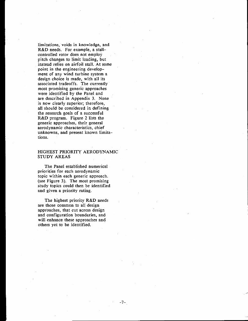
limitations, voids in knowledge, andR&D needs. For example, a stall-controlled rotor does not employpitch changes to limit loading, butinstead relies on airfoil stall. At somepoint in the engineering develop-ment of any wind turbine system adesign choice is made, with all itsassociated tradeoffs. The currentlymost promising generic approacheswere identified by the Panel andare described in Appendix 3. Noneis now clearly superior; therefore,all should be considered in definingthe research goals of a successfulR&D program. Figure 2 lists thegeneric approaches, their generalaerodynamic characteristics, chiefunknowns, and present known limita-tions.
HIGHEST PRIORITY AERODYNAMICSTUDY AREAS
The Panel established numericalpriorities for each aerodynamictopic within each generic approach.(see Figure 3). The most promisingstudy topics could then be identifiedand given a priority rating.
The highest priority R&D needsare those common to all designapproaches, that cut across designand configuration boundaries, andwill enhance these approaches andothers yet to be identified.
-7-

3210
gTJ:
Highest PriorityHigh PriorityI.Ow Prioritybes N& Apply
STEADY AERODYNAMICS
1. AIRFOIL STUDIES:2-D3-DEFFECT OF ROUGHNESSAIRFOIL DEVELOPMENT
2. WAKE ANALYSIS
3. MECHANISMS :HIGH LIFT DEVICESSEPARATION CONTROL DEL71CES
4. TESTING METHODOLOGY
UNSTEADY AERODYNAMICS
1.
7-.
3.
4.
5.
6.
DYNAWCSTALL:2-D HYSTERESIS3-D HYSTERESIS
AIRFOIL DEVELOPMENTSTUDIES:DELAYED STALLSOFT STALLREPEATABLE STALLINSENSITIVE STALL
EFFECT OF ROUGHNESS
AIF.FOIT.DEVICES
TESTING METHODOLOGY:
WIND TUNNEL TESTINGTOTAL SYSTEM (FIELD) TESTING
PREDICTION Ol?PERFORMANCE
ROTOR STABILITY
INFLOW MODELS:
1. STEADY, UNIFORM2. STEADY, NONUNIFORM3. UNSTEADY, UNIFORM4. UNSTEADY, NONUNIFORM5. STOCHASTIC
INTERFACE TOPICS:
1. AEROELASTICITY2. CONTROL SYSTEMS3. SHUTDOWN SYSTEMS4. INTERFERENCE:
WAKE MODEL DEVELOPMENTCOMPONENT lNTERFERENCT? DEVELOPMENT
AolxHzE
dolxi+g
v
nwmr?
0110011122001211100211110011
1110012
11 1’ 0 0 0 11110001
1110011
3 3333233333323
22233122223322333332333333233333323
2223312
33333333333323
2223323
2220023
111331122211233 33113333311332221122
333333313313231011001
22222221111111
FIGURE 3. WIND TURBINE RESEARCH NEEDS AND PRIORITIES
CHAPTER 3. WIND TURBINE AERODYNAMIC STUDY AREAS
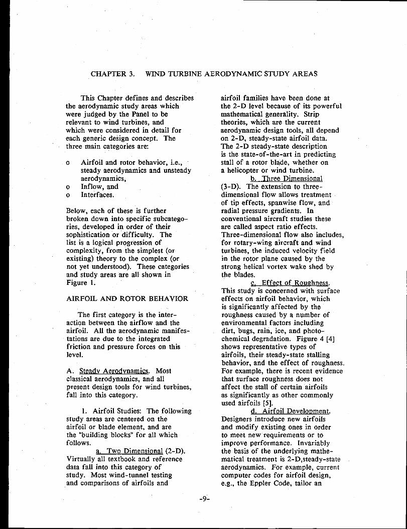
This Chapter defines and describesthe aerodynamic study areas whichwere judged by the Panel to berelevant to wind turbines, andwhich were considered in detail foreach generic design concept. Thethree main categories are
o Airfoil and rotor behavior, i.e.,steady aerodynamics and unsteadyaerodynamics,
o Inflow, ando Interfaces.
Below, each of these is furtherbroken down into specific subcatego-ries, developed in order of theirsophistication or difficulty. Thelist is a logical progression ofcomplexity, from the simplest (orexisting) theory to the complex (ornot yet understood). These categoriesand study areas are all shown inFigure 1.
AIRFOIL AND ROTOR BEHAVIOR
The first category is the inter-action between the airflow and theairfoil. All the aerodynamic manifes-tations are due to the integratedfriction and pressure forces on thislevel.
A. Steadv Aerodynamics. Mostclassical aerodynamics, and allpresent design tools for wind turbines,fall into this category.
1. Airfoil Studies The followingstudy areas are centered on theairfoil or blade element, and arethe “building blocks” for all whichfollows.
a. Two Dimensional (2-D).Virtually all textbook and referencedata fall into this category ofstudy. Most wind-tunnel testingand comparisons of airfoils and
airfoil families have been done atthe 2-D level because of its powerfulmathematical generality. Striptheories, which are the currentaerodynamic design tools, all dependon 2-D, steady-state airfoil data.The 2-D steady-state descriptionis the state-of-the-art in predictingstall of a rotor blade, whether ona helicopter or wind turbine.
b. Three Dimensional(3-D). The extension to three-dimensional flow allows treatmentof tip effects, spanwise flow, andradial pressure gradients. Inconventional aircraft studies theseare called aspect ratio effects.Three-dimensional flow also includes,for rotary-wing aircraft and windturbines, the induced velocity fieldin the rotor plane caused by thestrong helical vortex wake shed bythe blades.
c. Effect of Roughness.This study is concerned with surfaceeffects on airfoil behavior, whichis significantly affected by theroughness caused by a number ofenvironmental factors includingdirt, bugs, rain, ice, and photo-chemical degradation. Figure 4 [4]shows representative types ofairfoils, their steady-state stallingbehavior, and the effect of roughness.For example, there is recent evidencethat surface roughness does notaffect the stall of certain airfoilsas significantly as other commonlyused airfoils [5].
d. Airfoil Development.Designers introduce new airfoilsand modify existing ones in orderto meet new requirements or toimprove performance. Invariablythe basis of the underlying mathe-matical treatment is 2-D,steady-stateaerodynamics. For example, currentcomputer codes for airfoil design,e.g., the Eppler Code, tailor an
-9-

Thin airfoil SaII, Laminar separation bubble
0.9
Contributirm factors Sal! characteristics—-1. Low RN I 1. Gradual lift stall2. Sharp nosa I 2. Abrupt moment stall1. No LE roughness 3. .IOQ below stall
4. Hysteresis
-TE?cl-
—Trailing edge stall
Contributing factors Stall characteristics.
1. Large TE angleI
1. Gradual lift stall2. Thick, turb EL 2. Gradual moment stall3. Blunt”nose I 3. NO hyssemai$
Leading edga stall
Laminar wparation bubbleRaiw RN
+Increase tb,ckoess
~ Bubble explodes
Droop noseI
*
10
Raise RN
!
FIGURE 4. AIRFOIL STALL SELECTION CHART [4]
. --
~ Increase thickne. ~-

airfoil shape to a given table ofdesired conditions and parameters[6]. Inthepast, much airfoildevelopment (e.g., the NACA 4- and5-digit series foils) was done empiri-cally in wind tunnels.
2. Wake Analysis: This is thestudy of the vortex wake of arotor or propeller, in order toassess the induced velocity causedby this wake; see Figure 5 [7].This induced velocity results inangle of attack changes along theblade which must be accounted forin order to predict loading. Agood approximation of the vortexwake geometry and induced velocityis essential for good performanceanalysis.
3. Mechanisms: Mechanisms areadded to otherwise clean aerodynamicdevices in order to extend theoperating envelope or improveperformance for certain conditions.For example, fixed-wing aircrafthave trailing-edge flaps whichgenerate large lift to allow veryslow landing and takeoff speeds,without stall. Devices are alsoused to increase performance inother areas.
a. Hi~h-Lift Devices. Asmentioned above, these are used toextend the flight envelope of wingsand (sometimes) rotor blades, toallow flight in conditions beyondnormal operations, which is simplycruise in the case of fixed-wingaircraft.
b. Se~aration Control Devices,These include vortex generators,flow energizers, attachment promoters,and any other devices which attemptto delay the stalling or separationof a given aerodynamic surfacewhich would normally otherwise bestalled or separated; see Figure 6[8]. Again, these are used to extendthe envelope of flight, and areusually used to enhance controlla-bility or consistency rather thandirectly increase lift or speed.
4. Testing Methodology Practic-ally all steady-state aerodynamictesting is done in wind tunnels.These wind-tunnel data are usuallytime series results or compilationsof average data. Some flight dataare used under conditions where agreat deal of effort is expended toproduce as close to steady stateas possible.
B. Unsteadv Aerodynamics. Unsteadyaerodynamics is concerned withairfoil and rotor behavior undertime-varying conditions. Unsteadyeffects have been recognized sincethe early days of airfoil investigation.Often an unsteady aerodynamicphenomenon, for example, a humming-bird’s flight, can be described andexplained qualitatively, but cannotbe described mathematically.Without a sensible mathematicaldescription, the effects, bothdetrimental and beneficial, cannotbe assessed. The study of airfoilsin unsteady conditions is importantfor aircraft, but is essential forwind turbines.
1. Dynamic Stalk Dynamicstall is described in Appendix 2[9]. Its associated loss of lift andimpulsive pitching moment occuras a result of many factors, includingairfoil shape, starting angle ofattack, rate of change of angle ofattack, and the starting point ofthe cycle (that is, the time historyof the motion). The resultingstall is usually represented as ahysteresis loop on the traditional2-D lift and moment airfoil curves;see Figure 7. When dynamic stalloccurs, it is almost always unexpected,abrupt, and inconsistent, and hassignificant effects on rotors andaircraft.
a. Two-Dimensional Hvste--. The most basic level ofstudy of dynamic stall assumes ablade of “infinite aspect ratio”
-11-

FIGURE 5. ROTOR WAKE GEOMETRY [7]
FRONT VIEW APPROACHING
(LOOKING DOWNWJND) SIDE VIEW FLOW

FIGURE 6. SEPARATION CONTROL DEVICES [8]
,C5==scoop
e////’
//
/“+/
Tapered Fin
-13-
,4 ,<,.’..4 .
ShieJded Plow
Twist Interchanger
Dome
/sip‘+
Finite Wing

(5Z
FIGURE 7. DYNAMIC STALL OF NACA 0012 AIRFOIL [9]
CY=15°+lQ0 sin ~j ‘= ’0.15.k=zum Re=2 5X10⁶
CNMAX
BEGIN ~\/(
II\ 1 -z;
MOMENTSTALL
//+sTATc““-1t“
I
. .:*.,,1A /I I
o 5 10 15 20 25
\
;,
INCIDENCE , CY, kg .
-14-

i.e., 2-D) oscillating under controlledconditions in a wind tunnel. Thisis an attempt to produce conditionswhich are identical along the testblade, or truly two-dimensional.Such studies are usually concernedwith determining what set of condi-tions and time histories producewhat hysteresis effects for a givenairfoil.
b. Three-Dimensional Hvste-&. As in steady-state work, thenext step is to introduce finitespan, or radial pressure gradients.Again, three-dimensional studiesattempt to assess the effects ofphenomena such as spanwise flow,sweepback, and tip effects on dynamicstall.
2. Airfoil Development Studies:When sufficient work is done to under-stand, describe and sensibly predictdynamic stall, it should be possibleto design airfoils and blades whichexploit dynamic stall effects. Thereappears to be a large amount ofmanipulation possible, judging fromrecent tests [10]. Some effectsmay be possible with simple airfoilgeometry modifications, while othersmay require devices such as flaps‘or slats.
One of the interesting featuresof dynamic stall is that all airfoilsseem to behave the same once thedynamic stall events have reachedan irreversible point, but theybehave very differently up to thatpoint. It is also very important inwind turbine applications that theunsteady effects described belowhave no associated drag penaltysince that would significantly reducethe output torque of the wind turbine.
a. Delayed Stall. The firsttwo categories, delayed stall andsoft stall, avoid the hysteresis ofthe irreversible dynamic stall event.Both approaches cause airfoil liftand moment to exceed static valuesfor a short time and then return to
the static values, with no otherpenalty. Delayed stall is depictedon the curve in Figure 8. It hasbeen reproduced in wind tunneltests [10], wherein the static stallpoint was greatly exceeded duringa dynamic airfoil pitching cycle (alsoshown on the curve). The associatedpitching moment curve also didnot contain the large impulsivemoment hysteresis. If this airfoilmodification is used, lift coefficientswill reach very high momentary valuesand the lifting flow will remainintact. Essentially, the lift-curveslope stays constant, as can beseen in Figure 8. A consequenceof this for rotors is that theaerodynamic damping in flappingmotion is dependent on this beingtrue.
b. Soft Stall. Soft stall,also depicted in Figure 8, is moredifficult to achieve than delayedstall. Here the lifting flow is notcompletely lost, since the valuesreturn to the static values afterthe cycle just as above; the liftcoefficient does not continue torise, but levels off instead, leadingto the term “soft stall.” The largeimpulsive airloads present in delayedstall will not occur, but aerodynamicdamping will be affected since thelift-curve slope has been changed.
c. Re~eatable Stall. Oneof the most difficult aspects ofunsteady aerodynamics is the widevariation of response under appar-ently identical conditions. Anexample is the stall-spin event infixed wing aircraft; even underthe apparently same conditions ofstall entry, one time the left wingmight break, and another time theright one might. Present consensusabout this is that the outcome isvery sensitive to flow details suchas microturbulence. Similarly,even under apparently identicalwind-tunnel conditions dynamicstall hysteresis results may have a
-15-

FIGURE 8. DELAYED STALL AND SOFT STALL
DELAYED STALL
SOFT STALL
./
,/I 1 1 1 1
ANGLE OF ATTACK
---- STATIC VALUE
FULL DYNAMIC STALL
DELAYED STALLSOFT STALL
-16-

FIGURE 9. DYNAMIC STALL VARIATION
~—
/’ ‘\
/
II\
/ \
/ \
\
\
I/
ISTATIC
/
VALUE
UNSTEADY RANGE
ANGLE OF ATTACK
-17-

wide variation, this is depicted inFigure 9. The study of repeatablestall in unsteady conditions shouldreveal more about these subtleaerodynamic effects.
d. Insensitive Stall. Oncethe unsteady “repeatability” hasbeen described, it is possible todesign it into the performance of arotor blade or wing. Insensitive stallmeans simply that the airfoil willshow the same hysteresis under awide range of conditions and timehistories of motion.
e. Effect of Roughness.Airfoil surface roughness has animportant effect in the steady-statecase, as depicted in Figure 10 [11].In the unsteady case, roughness islikely to have a much more signif-icant effect, especially in view ofthe subtle behavior modificationwhich may be attempted in unsteadyairfoil development.
3. Airfoil Devices Unsteadyaerodynamic devices include flaps,slats, and high lift devices. Theirlikely uses will be to foster delayedstall, soft stall, repeatable stall, andinsensitive stall. The examplegiven under delayed stall [1O] wasachieved in wind-tunnel tests witha leading edge slat modification tothe airfoil.
4. Testing Methodology Allthe aircraft and wind turbinesoperating in the unsteady environmentare potential testbeds for unsteadyaerodynamics. In fact, aggravatingfluctuating airloads caused by dynamicstall are usually discovered first inflight testing (e.g., retreating bladestall on helicopters in forwardflight). Systematic study usuallythen follows. To achieve understand-ing, controlled experimentation isrequired, and variation of a singleparameter is the objective. This isfrequently difficult in wind tunnelsand impossible in system testing inthe field.
a. Wind Tunnel Testing.Wind tunnels are being used increas-ingly in the study of unsteadyaerodynamics. A very clean (lowturbulence) tunnel can be used for2-D studies of dynamic stallhysteresis, for example. Othertunnels use 3-D models of terrainand buildings and simulate unsteadyatmospheric flow [12]. Wind -tumnelstudies of the airfoil are doneunder 2-D circumstances, andstudies of blades and rotors in3-D circumstances. This field iscalled wind engineering, and anyadvances in exploiting unsteadyaerodynamics will probably be seenin these tests before they will bedescribed mathematically.
b. Total Svstem (Field)m. There must eventuallyexist the capability to do completesystem testing, in the field, forunsteady aerodynamics. Existingsystems will be useful if adequateand effective instrumentation andconditions can be maintained.
5. Prediction of Performance:It is clear that the logical progressionof aerodynamics work is to studyand develop the airfoil (1), thenthe rotor (2), and finally theperformance prediction code (3).In steady flow, rotor performanceis largely determined by the vortexwake, and to date a premium ha~sbeen thus placed on the study ofthe fixed. wake. In unsteady flow,the wake strength and geometryvary, making the problem morecomplex.
However, describing the wakeeffect on the rotor is not a largestep, since the analysis methodsare well in hand to describe varying,nonuniform inflow effects on theangle of attack distribution of theblade. Performance includes bothproductivity and reliability. Athree-dimensionally varying wakegeometry will place vorticity nearenough to the blade that impulsive
-18-

FIGURE 10. AIRFOIL SURFACE ROUGHNESS EFFECTS IN STEADY STATE [11]
2.0
1.6
1.2
0.8I
m. .......................
1 1 I I I7x 105 106 3XI06 6x 10⁶
REYNOLDS NUMBER, RN
AIRFOILSNACA 0012 NACA4415NACA 4412 NACA 23012
NACA 23015
K●..*:*:O:*:O:O . . . . ..*..**O>OO** .
●.,.*.*. . . . . . ..< . . . . . . . . . . . . . . . . . . . . . ● .
.................................................................................................. ,. ............................................................................. ... ................................................................................................ ................................................................................................................. ..““ “‘ ..-.................................................
‘ SMOOTH
ts 1 I I I I
-19-
—7X 10⁵ 106 3X10⁶ 6X10⁶
REYNOLDS NUMBER, RN

airloads will result. This unsteadyeffect, also seen in steady-statetests where the wake is fixed,decreases the fatigue life of the biades.
6. Rotor Stability Stability ofaircraft is complex, involving sixdegrees of freedom even for anassumed rigid flight vehicle; bycontrast, wind turbines have only oneequivalent degree of freedom, yaw.Using momentum/blade elementtheory (e.g., the PROP code) [13],it can be shown theoretically thatin steady state, no aerodynamic yawingmoment is produced by a windturbine rotor [14]. A static yawingmoment will be produced only inthe presence of nonuniform inducedvelocity and blade motion. Inunsteady conditions, yaw stability ismore complex, Again, the unsteadygeometry and strength of the wakeare of crucial importance.
INFLOW MODELS
The second major aerodynamictopic is the inflow to the rotor,which causes the unsteady effectsdescribed above. An adequatemathematical description of the inflowwill allow a variation in angle ofattack of the rotor. This factordominates the unsteady response.The inflow consists ofi
o
0
0
all
by
wind speed and directionfluctuations,terrain-induced fluctuations,andinterference-inducedfluctuations,
of which are unsteady.
Each component can be representeda non-stationary, 3-dimensional
vector quantity, which is non-sta-tionary. This means that it is notsimply characterized by an averagevalue and a complete set of momentsof fluctuations about that mean;
e.g., the average wind speed dependson the integration time and dc~esnot reach a constant even for largetime [15].
The specification of these compo-nents in a form suitable for inflowcalculations is far beyond presentcapability. One simplifying assumptionis to specify only the horizontalcomponent of inflow (wind), whichis primarily responsible for angle ofattack variation; this can be donevia linear superposition. Thismakes the problem sensible an(dtractable for the present. A newfield of study must be developedto go furtheq the Panel callsthis aerometeorology, and discussesit in Chapter 6 of this Report.
An example of how unsteadyfluctuations in the atmosphere arepresently studied is given in Figure11 for the simple case of a verticalwind gust on an aircraft in cruise.Isotropic turbulence, and a VonKarman power spectral density,are assumed. A simple cosine gustprofile with a certain longitudinalwavelength is extracted from themodel, and its effect on the aircraftis estimated in the following waythe atmosphere, exclusive of thegust, is assumed to be steadystate for a short time. The equationof motion of the aircraft, whichin general involves three spacevariables (x,y,z) and time, is simplifiedby assuming simple time-dependentrectilinear flight. An effectivepitching rate is calculated fromthe gust profile, and the resultingangle of attack change is calculatedfrom that. Finally, the airload iscalculated from the transfer functionof the “point model” of the rigiclaircraft dynamics.
For wind turbines, the descriptionmust be able to go far beyondthis. The inflow is inherentlynonuniform and unsteady. A logical
-20-

FIGURE 11. AIRCRAFT GUST MODEL
1“I
—
I
I
t●
z
t
AIRCRAFT WING
BENDING
MOMENT
ANGLE OF
DISTANCE TRAVELED THROUGH GUST
-21-

way to proceed is to build a hierarchyof descriptors of these components,of increasing complexity and realism,leading eventually to an ability todescribe both spatial and temporalvariations of the inflow. In thefollowing descriptions of such ahierarchy, steady and unsteadyrefer to the time variation of theinflow, and uniform and nonuniformto the spatial variation.
A. Steadv. Uniform. Steady, uniforminflow is depicted in Figure 12.This is the classical wind-tunnelflow, and admits no variation ineither time or space.
B. Steady. Nonuniform. Steady,nonuniform inflow, shown in Figure13, has an inflow “front” whichtravels along with the horizontalflow. Linear wind shear might bethe first term in a series repre-sentation of such a field, and aparabolic profile might be another.Any mathematical function withparametric frequency or wavelengthmight be used in such a seriesrepresentation. Practically allpresent inflow modeling is at thislevel of description.
C. Unsteadv. Uniform. Unsteady,uniform inflow is simply defined atpresent within the community as a“rotor gust front”. The profile isuniform (constant), but the valuechanges with time. Hence the gusthas “shape” and duration, as shownin Figure 12, and envelops therotor uniformly. However, a givenatmospheric turbulence eddy mayappear nonuniform to a large diameterrotor, and uniform to a small diameterone (see Figure 14); this illustratesthe need for an adequate (i.e.,wavelength) description of spatialvariation in the inflow.
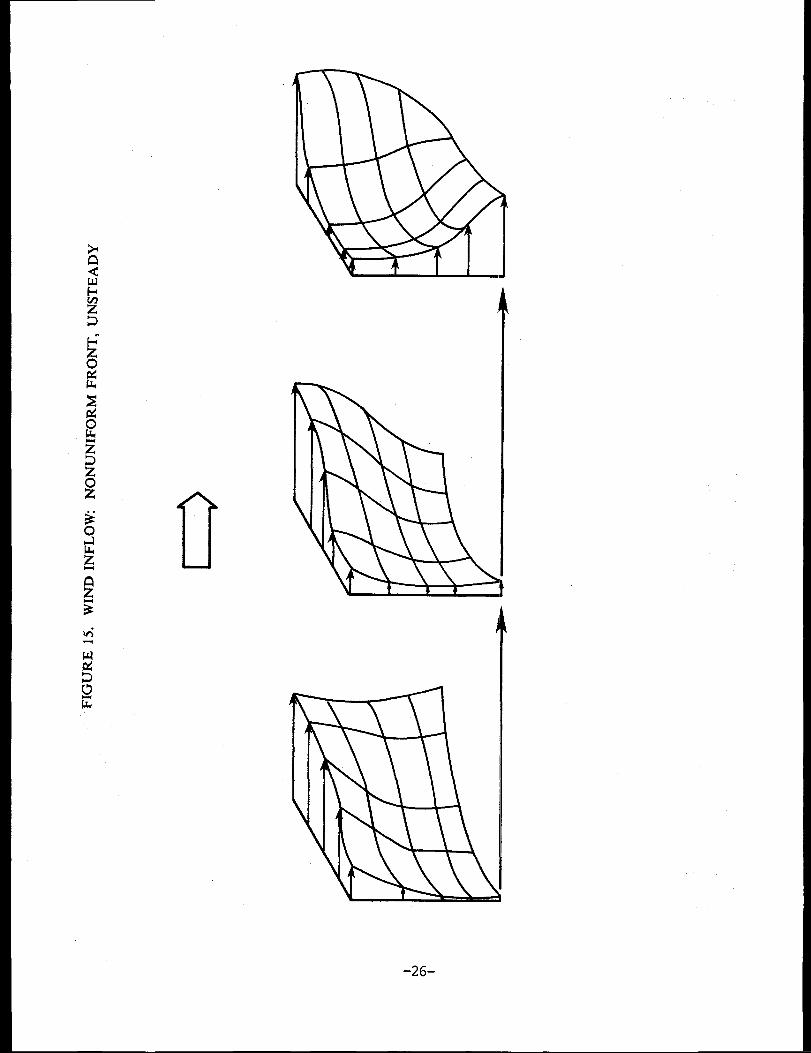
D, Unsteadv. Nonuniform. Theactual inflow is both unsteady and
-22-
nonuniform,15. To firstinflow frontto have 2-D
as depicted in Figureapproximation, themay perhaps be takenshape similarity cm
symmetry; in general, variationswill affect the front shape as ‘wellas magnitude.
E. Stochastic. Up to thispoint, the discussion has concerneddeterministic descriptions of inflow.If a more general stochastic represent-ation is successfully developecl, thepowerful tools of frequency analysisand statistical methods can be used(Figure 16). Stochastic methodsare the most effective way ofstudying these. Most turbulencework to date in the atmosphericphysics community has been accomp-lished in the frequency/wave numberdomain with statistical methods.
INTERFACE TOPICS
The third and last category ofaerodynamic study concerns topicsin which the aerodynamics plays amajor or contributing role throughthe unsteady airloading, but whichdepend also on other disciplines.
A. Aeroelasticitv. Here the majorinterface is with structures, whichintroduce both inertial and elasticforces which may lead to instabilities.Mass and motion are introduced.,and depend on aerodynamic forces.The resulting feedback is alsoimportant to aerodynamic performancecalculations, since blade motionsaf feet angle of attack distributicmsand time variations.
B. Control Svstems. Controlsystems are used to extend the opera-tional envelope by decreasingloads, and to capture more energyby improving efficiency. The fourcontrol regions of wind turbinesare discussed in Appendix 2 andshown in Figure 17; they are (1)

FIGURE 12. WIND INFLOW UNIFORM FRONT, STEADY AND UNSTEADY
STEADY
--1
Y_
UNSTEADY
Iv’’’’”●
WTloN~
-23-

la--I
Pmt-7f–1/l——
/
/’/’
LINEAR
FIGURE 13. WIND INFLOW. NONUNIFORM FRONT, STEADY
I
PARABOLIC COMPLEX

Ly-i
FIGURE 14. ATMOSPHERIC INFLOW FLUCTUATIONS
vi
-26-

NONUNIFORM FRONT, UNSTEADY (CONT’D)FIGURE 15. WIND INFLOW
-’7‘.
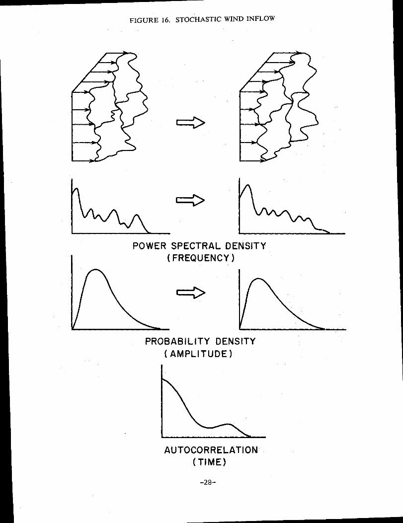
FIGURE 16. STOCHASTIC WIND INFLOW
POWER SPECTRAL DENSITY
( FREQUENCY)
PROBABILITY DENSITY
(AMPLITUDE)
AUTOCORRELATION(TIME)
-28-

FIGURE 17. WIND TURBINE GENERAL CONTROL REGIONS
@
II
II
CUT-IN1
SHUT DOWN
I
IIII
II
\ - A v /
RISING CONTROLpOWER ON POWER
WINDSPEED
WINDSPEED
-29-

cut-in, (2) rising power, (3) loadlimiting, and (4) shutdown. Loadlimiting and power limiting are notnecessarily the same; load limitingmay occur first, in which case thecontrol system extends the envelopeof operation by decreasing theexpected limit loads. A controlsystem adds additional degrees offreedom and feedback paths, andhence allows new instabilities andpotential resonances.
C. Shutdown (Emer~encv) Svstems.Shutdown systems are the specialcontrol systems used in controlregion (4). They are intended tolimit the exposure to high wind speeds(e.g., hurricanes), loss of drive load(overspeed), or adverse environmentalconditions such as icing. Thesystem loads are primarily aerodynamicexcept for overspeed conditions,where inertial (centrifugal) loadsmay be as high as aerodynamicloads. Most such systems of interestfunction aerodynamically; examplesinclude pitch feathering devices,ailerons, blade tip tabs, and spoilers.
D. Interference. By “interference”is meant the aerodynamic interferencewith other bodies. This categoryincludes wakes from other turbinesas well as wakes from componentssupporting the turbine.
1. Wake Model DevelopmentModeling of the wake structure anddecay is important for array designand siting plans. It involves describingmathematically the wake of theturbine, and assessing the blockageand velocity decrements in thedownstream turbine inflow.
2. Component InterferenceDevelopment Components whichproduce aerodynamic wakes includetowers, guys, stays, nacelles, androtor hubs. These wakes also influencethe inflow to the turbine.
-30-

CHAPTER 4. WIND TURBINE AERODYNAMIC RESEARCH NEEDS AND PRIORITIES
In the previous Chapter, theaerodynamic study areas which arerelevant to wind turbines weredescribed. In this Chapter, theseareas are discussed in relationshipto the generic design approachesconsidered by the Panel, andprioritized in order of generalimportance to the goals of thefederal R&D program.
The generic design approachesare discussed in detail in Appendix3. They represent the mostprobable configuration choicesavailable now, although newapproaches will appear as researchis done and new products aredeveloped. These are given inFigure 2, which shows the attri-butes, aerodynamic characteristics,chief unknowns and known limitations.
With the approaches defined, thePanel was able to construct amatrix of aerodynamic study areasvs. the generic approaches. Asummary chart was then constructedwhich prioritized the aerodynamicstudy areas for each genericapproach. This chart is given inFigure 3.
A rating scale of O to 3 wasplaced on each topic, to depict therelative need for that approach.The ratings should be interpretedas followx
Rating OInterpretation Does not apply
to this approach; or advancement inthis area will not result inimprovements to this approach.
Rating: 1Interpretation Work should be
done in this area, but it should be
low priority.
Rating 2Interpretation:
done in this area,high priority.
Rating: 3Interpretation:
Work must beand should be
Work shouldstart in this area, must be done,and will result in major improvementto this approach; the highest priority.
For each generic designapproach, the rankings indicatethe order of importance for effortin each study area. This can beseen by referring to Figure 3. Inthe opinion of the Panel, substantialeffort in the highest priorityareas, as indicated, can result inthe greatest improvement inperformance and reliability foreach approach.
The aerodynamic study areas,summarized in order of priority are:
Unsteady Aerodynamics
Dynamic Stall Understanding--
Develop an understandingof the 2-D and 3-Dhysteresis effects ofdynamic stall.
Testing Methodology forUnsteady Flow--
Stimulate complex unsteadyflows in wind tunnel andtotal system (field) testsin order to exploit dynamicstall effects.
-31-

Airfoil Development Studies forUnsteady Flow--
Initiate a design process whichwill yield airfoils specifi-cally suited for unsteadyflow, and which considersthe significance ofi
o
00
dynamic stall repeat-ability and insensi-tivityairfoil roughnessdelayed stall and softstall
o performance and predictiono rotor stability, ando airfoil control devices.
Wind Inflow Models:of Aerometerology
The Development
Establish a new study termedaerometerology, which willattempt to develop realisticinflow models for the assessmentof unsteady effects, includingthe specific cases ofi
o unsteady, uniform in-flow--or representation ofthe uniform gust front;
o unsteady nonuniforminflow- -or representation offrozen turbulence;
o steady, nonuniforminflow--or representation ofsteady inflow fronts;and
o stochastic inflow--or representation ofinflow in the frequency/wave number domain.
Interface Topics
Aeroelasticity--
Develop a methodology fordefining the unsteadyairloads which must beincluded in the structuraldynamic models.
Control Systems--
Investigate the performanceand reliability benefits tobe obtained with externalcontrol actions, such asailerons, in steady andunsteady flow.
Wake Model InterferenceDevelopment--
Develop and verify a modelfor the structure and decayof the unsteady wind turbinerotor wake.
Component WakeDevelopment--
Interference
Develop and verify mo{ielsfor the structure and decayof the unsteady wakescaused by turbine componentssuch as towers.
Shutdown (Emergency) Systems--
Develop an understandingof the behavior of airfoilsunder extreme conditions,and at very high angles ofattack, such as a movingaileron in separated flow.
In addition, further steady-state aerodynamics studies shouldbe continued in order to provide asuitable data base for the above
-32-

investigations and lend insight intothe new physical and mathematicalmodels and design tools which mustbe used.
Steady Aerodynamics
Three-Dimensional Flow--
Assess the degree of 3-Dor spanwise flow whichoccurs under typicalconditions, and relate thatto the inflow and turbinewake geometry.
Wake Modeling- -
Develop and verify amodel of the turbine vortexwake geometry suitablefor performance andstability studies.
Effect of Roughness in SteadyState--
Develop an understandingof environmentally-induced airfoil surfaceroughness on airfoiltransition and separationin steady flow.
Airfoil Mechanisms--
Investigate the effect ofairfoil mechanisms, suchas vortex generators, ondelaying turbine rotorstall and separation.
Two-Dimensional AirfoilDevelopment--
Develop a verifiedmethodology for tailoredwind turbine airfoil designin steady state to establisha database for futureunsteady airfoil design.
Testing Methodology for SteadyFlow--
Continue steady-statewind turbine testing inwind tunnels and in thefield, to acquire long-termperformance data and toinvestigate the benefits ofnew airfoils.
SPECIFIC AERODYNAMIC RESEARCHNEEDS BY PRIORITY
The highest priority researchareas are the ones which “cutacross the board”, i.e., are highpriority for each approach. Studyin these areas is discussed furtherin Chapter 5, The Need for BasicResearch. The research needs aredescribed here in order of theirpriority ranking, from the highestpriority to the lowest.
Work in all the areas shouldcontinue in order to provideacross-the-board progress, sincethat is what is required. Thelower priority items must havereached a level of maturity suchthat the more complicated, higherpriority items, can be sensiblydone. The key indicator of thismaturity is the existence ofeffective mathematical design tookwhich have been adequatelyverified by experiment. None ofthe wind turbine aerodynamicresearch areas can be said to haveachieved this level of maturity.
A. Unsteadv Aerodynamics.
1. Dynamic Stall Understanding(2-D and 3-D Hysteresis): This isthe highest priority with all theapproaches (with the exception ofhigh tip speed turbines, which arediscussed below). Both 2-D and3-D studies are essential to assess
-33-

the present HAWT turbines, anddesign tools must be much better ifmajor improvements are to be madelater. The situation is particularlyimportant for VAWT where verylittle is now known about theunsteady performance.
For VAWT turbines, the Panelbelieves that major improvement inperformance is possible if unsteadyflow can be exploited. 2-Ddynamic stall hysteresis studies willbe directly applicable to these turbines.
For HAWT turbines, the unsteadyairloads which now cause unexpectedfailure and fatigue are of primaryimportance. For stall-controlledturbines, dynamic stall must beunderstood and sensibly quantifiedbefore any major airfoil improvementdevelopment can take place.Pitch-controlled turbines aresubject to the same dynamic stallevents as are the stall-controlledmachines, and probably at a worseplace in the operating regime froma gust turbulence point of view,i.e., in the high wind load controlregion 3 [16]. There is alsoevidence from recent studies thatthe pitching rate (of a pitch-controlmachine) can greatly influenceunsteady airloading and gustresponse [17, 18].
Knowledge of the effect ofReynolds number on dynamic stallis necessary for both HAWT andVAWT in the large sizes.
The high tip speed ratio turbineis a special case. It is likely to beless susceptible to dynamic stallthan the others, since it operatesat lower lift coefficients which arefurther from the stall boundary. Also,inflow fluctuation causes correspondinglysmaller angle of attack variationfor high tip speed turbines (see Figure18). Nevertheless, this turbine will
still be vulnerable to inflow eventswhich lead to unsteady aerodynamics.
2. “resting MethodologyUnsteady aerodynamic testingmethodology should be developedin parallel with theoreticaldevelopment. Simulating complex,difficult-to-quantif y events willlikely be the source of most initialadvances in exploiting unsteady effects.
a. Wind Tunnel. Thecapability to do unsteady testingin wind. tunnels exists now, andoffers the chance to see andexplain an unsteady event beforeit can be quantified. However,much remains to be learned on theboundary layer level before wind-tunnel studies can be routinelyequated to free flight condition~s(see for example, Ref. [19]). Workin this area is of crucial importancesince the best chance for understandingunsteady boundary layer behaviorlies in carefully-controlled wind-tunnelstudies.
b. Total System (Fieldl.Total system tests are important,just as with aircraft, and will bemuch more difficult than wind -tunnel tests. The rotor behaviorand flow must be recorded, butthe fielcl inflow must also berecorded in sufficient detail topermit inflow modeling; this isdiscussed further in the sectionbelow on inflow. One attribute ofwind turbines is the relative easewith which a small-scale rotor canbe used in field testing. This ispossible since the range of Reynoldsnumber from convenient test sizeto actual rotor size, even withmultimegawatt machines, isrelatively small.
3. Airfoil Development Stuciies:a. Re~eatabilitv and Insensi ~
-. Once the repeatability Ofdynamic stall has been determinedand quantified, design process will
-34-

FIGURE 18. HIGH TIP SPEED ROTORS: EFFECT OF INFLOW
LOW TIP SPEED RATlO
Acz ANGLE OF ATTACK
DUE TO GUST
FLUCTUATIONS
CHANGE
AVv
HIGH TIP SPEED RATIO
v
AV
tWIND GUST
-35-
yield new airfoils and blades whichare insensitive to their fluctuatingtime history, These new airfoilswill dynamically stall in a predictableway, hopefully under a wide varietyof conditions. This characteristicis of paramount importance withstall-controlled wind turbines,which operate at high lift coefficientson the edge of dynamic stall formuch of their lifetime. It isimportant for this rotor to stall thesame way each time, since stall isthe only ioad control available.
Essentially none of a windturbines’ lifetime is spent in steadyflow, and this is particularly trueof VAWT, so the repeatability ofdynamic stall is a starting point forimproving its aerodynamics.Currently, not enough is knowneven to decide whether delayedstall or soft stall is needed forVAWT. Field tests show that thestraight-bladed VAWT is verysensitive to its collective pitchangle, which probably determineswhether the irreversible point ofthe dynamic stall hysteresis curveis met or exceeded [20].
b. Effect of Rou~hness.All wind turbines accumulatesurface roughness. Their degree ofexposure and accumulation is muchhigher than for conventionalaircraft, and wind turbines shouldideally require less surface maintenancethan aircraft. It is clear fromsteady-state tests that most airfoilsare sensitive to roughness.However, these steady-state testsare likely to apply with confidenceonly to the high tip speed ratiowind turbine, which operatesfurther from unsteady aerodynamicseffects than other designs. Thusunsteady tests must be done.
Field experience with stall-controlledHAWTS and VAWTS has shown theprofound effect of roughness on
-36-
energy output and m~(power rating) [21]. 1gives an extreme exalwherein the approxilcurves from field testdiameter stall-controlunder smooth and ro~conditions are given.state stalling behaviorexposed to varying dtroughness has receivecurrently receiving, aattention by the sailplwind turbine engineel[22, 23, 24]. It is notthe unsteady behaviolThis makes it imperalunsteady tests be donif they are to be conswind turbines.
c. Delayed S1~. When unsteadyhas been sufficientlymodifications to the tcharacteristic can be :deliberate design in oimprove performanceturbines. Soft stall mthe fatigue exposure :of increased output; cmight permit more exat the cost of high pe
Any improvementstall for VAWT affecoperating, envelope ofand not simply extrelturbulence bands, asfor HAWT. Therefo~stand to gain a greatdynamic stall can befor them,,
The uncertainty adesired dynamic stallshape for VAWTS alsstall-controlled rotorsHAWT or VAWT. Dthe advantage of higllift (and torque) forc[disadvantage of highairloads. Soft stall ha

FIGURE 19. EFFECT OF AIRFOIL ROUGHNESS ON POWER CURVE
CEu
30Q
o
CLEAN
!?
BLADES
DIRTY ‘
4 BLADES*
WIND SPEED
* This represents an extreme exanple
-37-
advantage of no increase infatigue loading, but the disadvantageof loss of beneficial aerodynamicdamping to motion and increased torque.
The same arguments for delayedstall and soft stall apply topitch-control and high tip speedrotors. However, the high tipspeed rotor has a lower priority byvirtue of its lower exposure todynamic stall conditions.
5. Rotor Stability: Of nextimportance is the stability of therotor system, which can beanalyzed when the unsteady wakehas been adequately assessed.This is clearly important for freeyaw HA WTS, which have aprofound requirement for dynamicstability of the operating rotorunder unsteady conditions. Onlyslight off-tracking in yaw canresult in loss of up to half aturbine’s annual output [26, 72].
4. Prediction of Performance:The next logical priority iscombining the rotor simulation andthe unsteady aerodynamics airloadcalculation to predict the unsteadyrotor performance. This includesprimarily analysis of the unsteadyvortex wake and its feedback effecton the induced velocity field whichdetermines rotor angle of attack.
For HAWT, the mathematicalmodel, and code, will generally bedifferent for the stability calculationthan the performance calculation,since the stabilizing airloads arein the flapping (lift) direction, andthe power-producing airloads arein the lead-lag (torque and drag)direction.
For the VAWT, the distorted,unsteady vortex wake probably hasa much greater influence on therotor performance than otherinflow perturbations. Initial testdata tend to confirm this [25]. Itis unlikely that confident performance,either unsteady airloading or torqueoutput, will be successfullypredicted for VAWT until theunsteady aerodynamics is muchfurther developed. In contrast withHAWT, there is no mathematicalcoordinate reference frame forVAWT in which the flow can beapproximated as steady state. Theprogressions of wake models, fromthe simplest to the complex, arevery different for VAWT andHAWT, and probably differentmathematical tools will be needed.
For HAWT, the study of theunsteady wake will enhanceperformance prediction, and alsoallow mathematical description ofthe wake physics for wake interferencedevelopment study.
It is generally agreed that it ispossible for any HAWT to be madeyaw-stable in steady flow, eitherupwind or downwind of the yawaxis, with proper blade design[27]. However, unsteady flow cancause selective dynamic stall onopposite sides of the rotor disk,creating a destabilizing yawmoment (see Figure 20). Yawdamping used to limit yaw ratesfor blade load control mightaggravate the yaw stability underthese unsteady stall conditions.Such behavior has been observedon operating wind turbines [26].
For tlhe VAWT, yaw stability isnot a concern since the VAWT isinsensitive to wind direction. Onepossible exception is the straighl-bladedVAWT with cyclic pitch control,which requires an inflow directionor stagnation locator to phase thecyclic pitch input properly (FigureA-13). This should be classifiedin the controls category below.
-38-

6. Airfoil Control Device~are distinguished from thedevices which will probably
These
beemployed in the airfoil de~elop-ment studies above, in which aleading edge slat, for example, maybe used to create tailored dynamicstall. Those devices are consideredpassive since they will likely be inuse during most of the operatingtime. Here we are concerned withactuating devices which are usedonly in certain conditions, such asflaps on conventional aircraftduring takeoff and landing, and canbe called active in terms ofdeployment.
The clearest applications ofadd-on airfoil devices, such as flapsand slats, are for increasing VAWTperformance and exploiting smallextensions of the operatingenvelope on low tip speed ratioHAWTS which have large blades. Itis not clear which devices will beuseftd or under which operatingconditions a high lift or stall delaydevice might be employed.
B. Inflow Models. The prioritizingof the levels of complexity ininflow models is straightforward.All the HAWTS have the same needfor a realistic inflow representation.This must be done before the unsteadyeffects can be assessed for eachoperating approach. Then therelative importance of dynamic stallcan be determined. Probably theinflow frequency ranges, forinstance, between large and smalldiameter rotors, will vary, butnothing can be said at this stagewith confidence about those ranges.
The situation differs for theVAWT, which is probably an orderof magnitude more vulnerable to itsown self-generated unsteady effectsthan to the unsteady effects of inflow.
This discussion can be thoughtof as the first level, or first orderinvestigation in a new field ofstudy which the Panel has termedaerometeorology, and which isdiscussed further in Chapter 6.
1. Unsteady, Uniform Thehighest priority is for study in thesimplest unsteady frame, that is, auniform gust front. Atmosphericturbulence can be intuitivelydecomposed into high-frequencyevents which are “smaller” thanthe rotor and result in degradingairloads over part of the rotordisc, and low-frequency eventswhich are “larger” than the rotorand represent potential capturableenergy. This is depicted in Figure14.
The “large” fluctuations are tofirst approximation in thisunsteady, uniform category. It isclear that the rotor diameter isimportant, but the relevant scaleparameter of the inflow cannot bedetermined until more is knownabout the conditions which precip-itate dynamic stall. It is likelythat rate of change of angle ofattack will have a dominantinfluence: it is directly propor-tional to the initial shape of theuniform gust front (sometimescalled rise time or slope in theliterature; see Figure 12).Obviously, the duration of thegust, along with the dynamics ofthe rotor and the frequencyresponse of any pitch change,determine whether the event willcause momentary airload changesor result in increased energy captured.
2. Unsteady, Nonuniform:The concept of frozen turbulenceallows spatial and time variationof the inflow front. Taking oneidealized eddy or fluctuation, andfollowing it through the rotor
-39-

FIGURE 20. YAW STABILITY
HI
B——
INFLOW
-1
WINDTURBINE
.—
180° /
6%T
Y-——
IVa,
GH BLADE ANGLE
ROTOR DISC ANGLE OFATTACK DISTRIBUTION
I0°
-40-
LOW BLADE
a,
ANGLE

plane, Figure 21 depicts theincrease of blade angle of attackon one side of the fluctuation(advancing side) and the decreaseof angle of attack on the other(retreating side). It is clear thatthe slope of the angle of attackcurve (rate of change), and the“static” value at the initiation ofthe fluctuation, determine whetherunsteady effects will occur.Instead of the entire rotor beingsubject to the unsteady effectequally, as with a uniform front,here only part of the rotor is vulnerable.
To differentiate between a“uniform” gust front which envelopsthe entire rotor and the “nonuniform”front which selectively affects therotor disk, the Panel suggests thatfield testing employ concentricrings of suitable anemometers.Figure 22 depicts such a fieldtesting arrangement. Inflow datataken simultaneously at manystations and heights on theconcentric rings will describe thescale of the fluctuations which passthrough the rotor plane, causingunsteady airloading or capturedturbulent energy at the windturbine. Both the spatial variation(nonuniformity) and time variation(unsteadiness) must be recorded.
3. Steady, Nonuniform Thearea of inflow investigation of nexthighest priority is steady, nonuniformflow. The simplest example of thisis linear inflow shear. There is nochange of the inflow front withtime; but there is, however,unsteady flow relative to therotating blade and its componentairfoil sections. Consider a simplelinear shear inflow. It is clearthat the normal shear flow can berepresented as an average uniformcomponent with a superimposedlinear shear (Figure 23). The shearinduces a once-per-revolution sinusoidal
variation in blade angle of attack,which can be verified in the bladeelement diagrams of the figure.The unsteady flow observed in therotating frame of reference on theairfoil occurs at the rotor passagefrequency, which is in turn the firstharmonic of a Fourier series.
It is an easy extension ofthought to visualize the otherinteger harmonics of the rotorfrequency, namely 2-per-revolu-tion, 3-per-revolution, etc., beingcaused by more complex inflowfronts. This is the mechanism bywhich the rotational harmonicspikes appear in the turbulencespectral density curve as seen bya rotating blade; see Figure 24[28]. It is simply a manifestationof the change in referencecoordinate system from stationaryto rotating. The importance ofthis to the aerodynamic investigationof wind turbine blades is thateven in steady inflow, unsteady airloadson the airfoil will result. It isnot yet clear which inflow frontsor harmonics are most likely toprecipitate unsteady aerodynamicevents on the blade.
Steady, nonuniform flow may bethe most practical representationof terrain and interference effects.It is possible that the variation incomplex terrain flow and inter-ference wakes will often be soslow as to be steady-state relativeto normal atmospheric fluctuations.The first-order yaw stability offree yaw turbines may be reducibleto a tractable steady flow problemif the inflow can be defined in thisway.
4. Stochastic: It is clear thatstochastic evaluation techniquescan be very powerful tools whenthe inflow is suitably mathematicallymodeled. A frequency or harmonic
-41-

FIGURE 21. CONCEPT OF FROZEN TURBULENCE
v –--3kflR
.
%———
4aR
I
‘mQR

FIGURE 22. TOTAL SYSTEM (FIELD) TEST ARRANGEMENT
\ \
\
.
\
\
\\4 )
\\
ANEMOMETERfinnAu-HKKAla
-43-

FIGURE 23. EFFECT OF SHEAR FRONT ON ANGLE OF ATTACK DISTRIBUTION
F?lBLADE ELEMENTI
aANGLE
——1
II
ILr’1.
a
2706
–/—— —
2II a—
160”I
u
0° 90° 180° 270° 360°
ROTOR AZIMUTH ANGLE
-44-
/
/
90°

FIGURE 24. ROTOR HARMONICS IN THE INFLOW POWER DENSITY SPECTRUM [27]
D=130m, rpm=15, Z=80m, D=lOOm. rom=17.5, Z=61m.U=ll.9m/S, L=522m U = 11.2/S,’L = 384m
Io’r— ROTATIONAL
‘--VON KARMAN?
k~c
:10-’ —
I,0-2 I,0-3 ,0-2 ,/-.l 10” 10
n,Hz
l—ROTATIONAL
n, Hz
D = 10m. rpm = 60, Z --20111,
U=lOOm,, S, L=155m
1o~ — ROTATIONAL
‘-- VON KARMANm
D L4m, rpm :
U=9m,S,L=
D = 40rn, rpm = 40. Z = 30m,U=103m/S, L=217rnr—ROTATIONAL
‘-- VON KARMAN
10:’ 102,..1 1@l 10’n,Hz
240,Z l!im,117M
W\\\\\\10-2 ,.-1 10“ 10’
n, Hz
Theoretical spectra for rotationally sampled wind speed for five sizes of windturbine. The dashed curves represent Eulerian spectra. The smallest turbine is 4 m indiameter; the largest is 130 m.
-45-

seems the most productive long-rangemathematical strategy to use in theinflow (aerometeorology) study,since it also allows frequencydomain analysis. Stochasticanalysis can be invaluable in anumber of specific ways since it permits:
o Representation of many datapoints taken in field tests.
o Rapid evaluation of fatigueloading.
o Comparison of hypothetical resultswith historical field data.
The Method of Bins [29] is asimple application of stochasticmethods to wind turbine fieldperformance. In order to be effec-tive, stochastic methods must berelated to theoretical predictivemodels as well as to field data.Only in so doing can general con-clusions be drawn, and anythingmore than an ornate description ofcomplex unsteady events be accom-plished.
A possible early application of astochastic approach will be inrepresenting the timewise variationof the inflow, that is, the unsteadi-ness of the flow as the fronttravels along. This could be aprobability distribution, or thelikelihood of experiencing a givenspatial nonuniformity in the inflow.In this example the spatial variation,e.g., the shape of the front, wouldstill be deterministic, perhaps aFourier series since the frequencyand wavelength concepts are sophysically valuable. In short, thecharacter of a time function wouldbe superimposed on a spatialrepresentation written in harmonicseries. This is depicted in Figure 25.
5. Steady, Uniform It couldbe argued that steady, uniforminflow is not relevant to thisdiscussion, and that this category
represents the stereotypicalthinking which must be abandonedin order that the rest of theinflow studies can bear fruit.
The only wind turbine approachfor which steady uniform inflow isconsidered presently adequate isVAWT, which requires considerablymore e:mphasis on the unsteadyinflow caused by its own motion.Clearly, the above discussion c~funsteady inflow also bsars onVAWT, and should eventually beconsidered after the more pressingstudies are done.
C. ~erface To~ics. These arethe wind turbine aerodynamicresearch needs for interdiscipli-nary studies involving windturbine systems.
1. ,Aeroelasticity As winclturbines become more structurallyefficient and lighter, the importanceof aerodynamic loading relative toinertial and gravity loading will behigher. At present, most successfulturbines operate at low tip speedratio and are intentionally heavy andstiff so that inertia and gravitydominate the load spectrum. Inthis way they minimize the impactof the unsteady aerodynamics towhich the y are subjected (seeAppendix 2). When inertial,structural elastic, and aerodynamicloads all enter, aeroelastic studiesbecome important, and there existsmore opportunity for instabilitiesand adverse resonance. The highestpriority research need in the areaof aeroelasticity is the definitionof the unsteady airloads whichforce the dynamic mathematical model.
For stall-controlled rotors themost likely phenomenon is stallflutter, which has been documentedin a large wind turbine [30]. It islikely tlhat stall flutter defines an
-46-

E1-Cn
FIGURE 25. COMPLETE WIND INFLOW REPRESENTATION
MODE
/
TIMEWISE
/
Idn31-
a
WAVELENGTH
SPATIAL
--47-

upper limit for the size of stall-controlled rotors with stiff,cantilevered blades [30, 31], and thatuse an airfoil that exhibits anormal loss of lift at stall. Partlyfor this reason, there is interestcurrently in the design of windturbine airfoils which do not havethis normal drop in CL-max atstall, but instead maintain a nearlyconstant lift coefficient after stall[32].
2. Control Systems Here theconcern is with external controlactions, such as pitch change,which can be programmed andactuated according to a presetstrategy or algorithm. Thisresearch area interfaces withautomatic control technology, and againthe research need is to provideunsteady airloading for the systemcontrol algorithms. Controlsystems add complicating degrees offreedom in damping, and instabil-ities to the system dynamics.Control actions also result ininduced unsteady airloads whichfeed back into performance androtor stability.
The ultimate control systemwould be an airfoil shape whichautomatically optimized theunsteady flow and shed unwantedloading. Some of this mayultimately be achievable for certainrestricted applications, such asmight be possible with soft stallfor stall-controlled rotors.
Control systems for pitch-controlledrotors (including partial span pitch)determine the proper average angleof attack for given conditions.Thus the operating envelope can beextended, and performance consequentlyimproved. Pitch change on aconstant speed rotor can be viewedas a method for maintainingconstant angle of attack on the
blade. Variable speed turbines,which use load control to operateat constant tip speed ratio, also maintainconstant angle of attack byadjusting their speed. This isshown in Figure 26. It is clearthat, given unsteady inflow, thletime required to readjust bladeconditions to the optimum dependson the pitching rate for theconstant speed rotor, and rotorinertia for variable speed. It isnot clear which “readjustment”approach results in higherperformance or reduced momentaryloading,, Research is needed tc~define the unsteady behavior wellenough that such design questionscan be answered.
Aileron control surfaces, as aweak substitute for blade pitchchange, can be used to controlaerodynamic load by spoiling, (orto delay stall [33]. The study ofsuch aerodynamic control motionsmust include unsteady flowconditicms as well as steady flow.Thus, there is a current need forinvestigations of control surfacemotions superimposed on theunsteady airfoil, and theircombined behavior.
3. Wake Model InterfaceDevelopment Modeling thestructur~e and decay of theunsteady turbine wake is of highpriority for array siting. Theliterature [34] shows a testexample where, in a low-turbu-lence wind tunnel, the powerdecrement at 10 diametersdownstream in steady flow was 40%for a representative turbine. Fieldexperience in arrays has not beenas severe [26]. This topic wasgiven a moderately high priorityby the Panel since the sitingbenefits could be large.
-48-

Ay) yj
Av
FIGURE 26. PITCH CONTROL VS. CONSTANT TIP SPEED RATIO (VARIABLE SPEED)
VARIABLE PITCH VARIABLE SPEIZD’
/
N/

Independent theoretical [35] andexperimental [36] studies ofturbine wakes should continue.The critical step, however, is thedevelopment of a suitable mathematicaldescription of the wakes within theconstraints of sensible unsteadynonuniform inflow methodology.Only in so doing can the effects ofturbine wakes be confidently assessed.
4. Component Wake InterfaceDevelopment Modeling of otheraerodynamic wakes is important,but probably not as important asthe turbine wake interferenceproblem. It is imperative here alsoto describe the component interferencein mathematical terms which arecompatible with the other mathematicalmodels.
The most important interferencewakes to study are those whichappear as unsteady inflow in therotating system. The most obviousexample is the tower wake for allVAWT and for downwind HAWTrotors. This wake has been shownto be a significant source offatigue on large downwind turbines[37], and this may ultimately limittheir size. As understanding andconfidence in the prediction of yawstability of rotors improves, thereshould be less incentive for placingrotors downwind of their towers.
5. Shutdown (Emergency)Systems The aerodynamic shutdown(e.g., high inflow, overspeed,out-of -balance) systems fall intothis category. The technology needis to understand the behavior ofairfoils under extreme unsteadyconditions and at very high anglesof attack, such as a moving aileronin separated flow. There is recentevidence that ambient turbulencelevels of the inflow can affect eventhe performance of airfoils in fullyseparated flow [38], which makes
this problem even more clifficult.
Pitch-controlled rotors areusually considered to have automaticshutdown capability by virtue ofblade pitching (feathering).
For :most stall-controlledrotors, however, blade pitch isfixed, so a loss of driven load willcause the turbine rotor tooverspeed until it reaches the“zero-slip” zero torque condition(see Appendix 2). Since the pitchangle is fixed at a relatively flatposition for reasonable performancein normal flow, the thrust (lift)on the blade under overspeed conditionsis very high. The turbine will bein Turbulent Wake State or VortexRing State, in which very highthrust coefficients are produced.This condition is the most difficultto analyze, and probably representsthe extreme aerodynamic loadingfor any rotor. An aerodynamic overspeedprotection or shutdown system maybe nearly impossible to analyze inthese conditions.
No estimate can be made atthis time of the likelihood ofshutdown conditions occurring forany particular turbine genericapproach. The most that can besaid is that the fixed-pitch,usually low tip speed ratio,stall-controlled, HAWT and VA”WTrotors are more dependent onthese control systems, and someimprovement in their understandingis possible.
D. -V Aerodynamics. Thelower priority topics are in steaclyaerodynamics. They have lowestpriority for VAWT turbines, sincethe flow never even approachessteadiness. However, there aresteady-state study areas that willlbenefit HAWT rotors. Largelybecause these areas are understood
-50-

in the traditional sense, and aretractable mathematically, substantialwork in all those areas is currentlyunderway, and should be continued.But major payoffs in performanceand reliability will not come untilsensible progress is made in theunsteady areas. Developments herein these steady-state areas willfacilitate that by providing adatabase for comparison and newattempts at mathematical modelingand design tools.
1. 3-D Flow. 3-D rotor flow insteady state has moderate importancefor conventional rotors, such aspitch control, variable speed, andlow tip speed ratio, especially withairfoil devices.
HAWT rotors operating at highlift coefficients and especially ifinboard blade sections are alreadyfully stalled, will have radialpressure gradients which can causespanwise flow. This has often beenobserved on low speed wind turbinesand is currently receiving attention[39, 40].
In steady state the effect of 3-D flow is to delay stall; inunsteady flow the effects areunknown. Therefore, a technologyneed is to assess the degree ofspanwise flow which occurs undertypical conditions, and relate thatto the inflow. It is likely that thesteady-state approximation will nothinder this study at first, since fewfield tests or wind-tunnel studieshave been done on the subject (seebelow). It is clear that the degreeof spanwise flow will have someinfluence on the unsteady airfoileffects, but the spanwise flowstudies must quickly turn tounsteady effects to be realistic.
Stall hysteresis (steady state) ofa candidate wind turbine airfoil has
been recently shown in a wind-tunnel test to be dependent onaspect ratio [41]. It is also clearfrom the body of literature of lowReynolds number airfoil workstemming from sailplane studiesthat Reynolds number is also astrong parameter that affects stallbehavior in a 3-D flow.
3-D flow on a blade can alsobe caused by a wake vortex stand-ing near the airfoil. Again, itseffects on the induced velocitydistribution should probably bemodeled in steady state first forexpediency, before the unsteadywork is done. This study areamost clearly affects turbines withstrong vortex wakes (low tip speedratio types) and those vulnerable towake stability (free yaw types).
2. Wake Modeling Of moderateimportance is the modeling of thewake in steady flow. Some workmust be done here before the unsteadywake modeling can begin. Confidentprediction of performance cannotoccur, however, until the wake isadequately modeled in unsteadyconditions. It is often suggestedthat lifting surface theory be usedto improve performance calculationsover the current blade element/liftingline approach [42], but clearly, thisapproach due to its steady-stateassumptions, may not improveperformance calculations forunsteady flow.
Modeling the steady-state wakewill also facilitate the stabilitystudy of free yaw turbines. It islogical to predict the staticaerodynamic yaw stabilizingmoment first. before more comt)licatedunsteady wake stability isattempted. Work on this hasalready been started, towardscalculation of the free wakegeometry [43, 44].
the
-51-
3. Effect of Roughnes~ Thereal technology need here is tounderstand the effect of environ-mentally induced airfoil surfaceroughness on airfoil transition andseparation. This is clearly a highpriority unsteady aerodynamicstopic. However, in steady state,work is still necessary as well toprepare a database for the unsteadydynamic stall studies.
Historical tests have shown theprofound effect of airfoil roughnesson the transition of the boundarylayer from laminar to turbulent andultimately on separation, but thesedata have not been fully applied tothe wind turbine field test results[11]. There is qualitative evidencethat the extreme roughness sensitivityof the NACA 230XX airfoil experiencein the field (see Figure 19) may bedue to simple underestimation ofthe sensitivity of the region of uppersurface high pressure to leading edgeroughness. That is, the “clean”airfoil in the field was able tosupport a high pressure distribution,and a corresponding high maximumlift coefficient, but the onlyslightly “dirty” airfoil had thisdrastically reduced. This is nodoubt partially due to the vulnerabilityof the “droop nose” of the 230XXto bug buildup [26].
Thus, there is a technology needto study the steady roughnesseffects from the field tests and inwind tunnel tests in order to beginto understand the effect ontransition of the boundary layerand incipient stall. In addition, thebenefits of steady vs. unsteadystudies of roughness cannot beassessed until proper inflow workhas been done to quantify thedegree of unsteadiness of the flow.
For very high tip speed ratioturbines, the flow is closer to
steady state because of the loweroperating lift coefficients andlessened fluctuations in angle ofattack (see Appendix 2). Here,the effect of roughness on rotorperformance can probably becon~ldently assessed with 2-Danalysis. Another compellingreason to study roughness effectsfor these rotors is that the hightip speed rotor will likely be verylow solidity and employ thinairfoils for higher L/D’s and lowernoise, and it is well known thatthin airfoils are much morevulnerable to vagrant roughnessthan thick airfoils.
4. Mechanisms This categoryincludes high Iif t devices, vortexgenerators, flow energizers,separated flow controllers, andattachment promoters. For flightvehicles, all are an attempt toextend the flight envelope slightlyby delaying stall and separation,usually cm a control surface, andall carry a slight drag or performancepenalty in some other part of theoperating envelope. Currently thedesign of these components isusually done for a steady flowcondition. Therefore, for wind turbines,which operate in unsteady flow,the steady-state analysis of thesedevices must be considered of Ic)wimportance, and might properly bereserved for the blade geometry(twist and taper) compromise stageof the industry design studies, andnot appear as a separate researchitem.
Studies of these devices mayhave application to turbines whichoperate at high lift coefficientsand which could benefit from smallextensions of lift during certainconditions [45]. The most obviouscandidate for this study is the lowtip speed ratio, high solidityturbine that has adequate chord
-52-

and structure to accommodate suchdevices. However, the degree ofpotential improvement cannot beassessed until the unsteady inflowis better known.
5. 2-D Airfoil Development Itis difficult to justify major further2-D steady-state airfoil studies,either theoretical or experimental,before more is known about theunsteady behavior of the newairfoils. However, it is clear thatproductive work is going on, andwill prove to be valuable. Currentlines of development in wind turbineairfoil R&D are
1. the fixed-wing airfoilapplications (e.g., LS- 1series [5]),
2. the empirical low Reynoldsnumber airfoil families (e.g.,Wortmann FX84W seriesfor stall-controlled windturbines [32]), and
3. the DOE-sponsored theoreticallyderived wind turbineairfoiI families (e.g.,Tangier-Somers Eppler codefamilies [6]).
Leaving aside the roughness questionfor a moment, the latter twodirections both show major possibleimprovements over the presentcommon wind turbine airfoils, theNACA 230XX and 45XX series. Itis not clear that their predicted
-53-
steady-state benefits will carryover into unsteady flow. Work shouldcontinue in the above airfoildevelopment directions in order toestablish a steady-state databasefrom which to understand andcompare the unsteady behavior yetto come.
Therefore, the straightforwardextension of fixed-wing airfoildesign technology one step furtherby varying the type of airfoil alongthe blade, and studies on theapplications of laminar andsupercritical conventional fixed-w~ng steady airfoils to windturbines are premature untilunsteady effects are betterunderstood,
6. Testing MethodologySteady-state testing shouldcontinue in order to acquirelong-term average data on
the
more
performance, and to investigatethe high angle of attack and stallbehavior of the candidate airfoils.Recent wind tunnel work [24] haspointed out the inconsistent andpoorly understood stall behavior ofa NACA 23024 airfoil at representativewind turbine Reynolds numbers,even in steady-state. Thus,candidate airfoils should be testedin wind tunnels and in the field toacquire a steady-state database tosupport the more crucial unsteadystudies which will eventually yieldthe best payoff.
CHAPTER 5. THE NEED FOR BASIC RESEARCH
The preceding Chapters havedealt with specific aerodynamicstudy areas and high priorityresearch needs for improvement inwind turbines. The Panel determinedthat the major work should be inunsteady aerodynamics and unsteadyrotor inflow. The Panel recommendsthat in these areas the emphasis beon basic research, rather than onapplied research.
DEFINITION OF BASIC RESEARCH
Basic research must be contrastedwith applied research, which isstrategic and is generally tied to aspecific configuration. Appliedresearch is also defined by itspertinence to a system rather thanan entire range of systems. Thebasic research which is called forhere must ultimately establish atechnology base strong enough thatdesign decisions can be made withconfidence and not by trial anderror as is often the case now.The Panel believes that verysignificant improvement in theperformance and economics of windturbines is possible given anadequate unsteady aerodynamicstechnology base.
PRESENT CONFIGURATIONSTUDIES
Configuration studies, designs,uses, and market bias, are thepurview and necessary concern ofindustry. But, in the opinion ofthe Panel, present wind turbineconfiguration and design studies inboth the government and industryprograms have yielded about asmuch as they can. It is now timeto turn to more basic studies. Asin the example of 2-D steady vs.unsteady airfoil design, there is
insufficient technology base andphysical understanding to plantests, to evaluate the results or tobuild adequate design tools. Designbias is common, and perhaps necessary,in configuration studies (i.e., HAWTvs. VAWT), especially in theabsence of compelling physical andtest evidence; however, design biasinhibits the process of understandingthe underlying physics.
Furthermore, the industryhardware--the aerodynamic technologywhich is being applied--is notmature enough to be used to framerealistic cost and technology goalsfor a strategic (applied research)plan. The industry R&D base isshallow, and has not pursuedlong-term unsteady aerodynamicsgoals. Organizations which havethe depth to undertake the complexunsteady aerodynamics studies arenow neecied. Such groups mightbe universities, national laboratories,or established research arms ofprivate industry. These R&Dorganizations remain aloof fromthe configuration and marketpressures, which are short term,and expend their effort on longterm programs.
THE NEED FOR UNSTEADYAERODYNAMICS EXPERIMENTALSTUDIES
Wind turbine theoreticaldevelopment has been seriouslyhampered. by a lack of credibleunsteady aerodynamics test data.Also, the generally-used HAWTprediction methods are heavilydependent on variations of steady-statemomentum theory [13], and theVAWT theories depend on steady-statestreamtube models, which largelyignore the unsteady effects [46].
-54-

For these reasons, the basicresearch program should include astrong experimental emphasis fromthe beginning. Tests need notnecessarily be performed on windturbine systems in the field, butunder carefully controlled conditionswhich lend description to theunsteady events, and allow qualitativeunderstanding. Turbines in thefield are too complex for thisprocess, but wind tunnels are not.
The initial advances in unsteadyaerodynamics will undoubtedly comefrom the wind-tunnel tests; forexample, terrain effects on sitingcan be studied this way. Thesetests, if done properly, can allowunsteady events to be describedand sensible empirical design toolsput into practice even before theycan be described mathematically.Historical examples are the NACA4- and 5-digit series of airfoils,which were developed empiricallyand have proved to be verysuccessful in aviation design. It isinteresting to note that up to thispoint the most common airfoils inuse on wind turbines are fromthese empirical families. Now, someof the promising new airfoils forwind turbine, the Wortmann FX84Wseries, are derived from morerecent empirical studies [32].
Experimental studies can alsohelp to define the proper directionsfor theoretical studies. An examplehere is the substantial wind-tunnelwork done on dynamic stall priorto any attempts to describe itmathematically [9]. The unsteadyaerodynamics capability to modelthe unsteady inflow is already wellin hand with boundary-layer windtunnels, which have been usedextensively in the field of windengineering, and will have muchmore application in aerometeorology.
The traditional scaling concerns ofReynolds number and Mach number,and wind-tunnel wall effects, arealready used routinely in wind-tunnelmodeling, even in unsteady flow.This is not to say the task isstraightforward, but rather, thatfruitful directions exist and arebeing researched [19].
Undoubtedly new scalingparameters will appear when theexperimental studies begin to bearfruit. These will likely concern thescale parameters of the inflowfluctuations and parameters at theairfoil surface, such as reducedfrequency. Field testing can alsobe productive, but only if theparameters are measured withenough care to extract theunsteady information.
DIFFICULTY OF THE PROBLEM
The nature of the basic researchgoals makes it difficult to estimatethe time or cost needed for therecommended research study areas.Innovations and discovery of newapproaches and solutions willmodify any set of strategic goalsor milestones adopted. The mostthat can be done is to define thehigher payoff directions which areclear now, and will eventuallybear fruit. We expect that thesedirections will also change in thefuture as knowledge is gained.
This course of action is not ashort-term strategy, but a major,patient, continuing long termcommitment. It depends onsubstantial directed resources andtalent that carefully constructstheoretical programs coupled withstrong experimental support, and isallowed to gain momentum over aspace of years, probably decades.
-55-
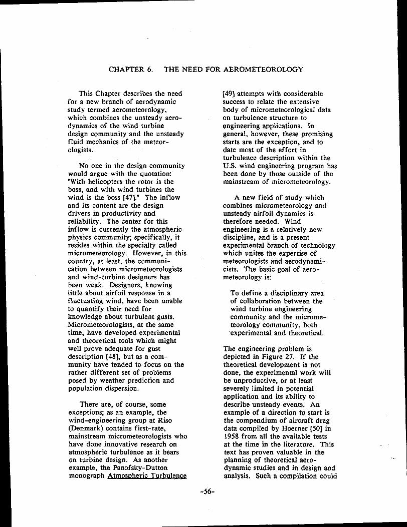
CHAPTER 6. THE NEED FOR AERONIETEOROLOGY
This Chapter describes the needfor a new branch of aerodynamicstudy termed aerometeorology,which combines the unsteady aero-dynamics of the wind turbinedesign community and the unsteadyfluid mechanics of the meteor-ologists.
No one in the design communitywould argue with the quotation’“With helicopters the rotor is theboss, and with wind turbines thewind is the boss [47].” The inflowand its content are the designdrivers in productivity andreliability. The center for thisinflow is currently the atmosphericphysics communitX specifically, itresides within the specialty calledmicrometeorology. However, in thiscountry, at least, the communi-cation between micrometeorologistsand wind-turbine designers hasbeen weak. Designers, knowinglittle about airfoil response in afluctuating wind, have been unableto quantify their need forknowledge about turbulent gusts.Micrometeorologists, at the sametime, have developed experimentaland theoretical tools which mightwell prove adequate for gustdescription [48], but as a com-munity have tended to focus on therather different set of problemsposed by weather prediction andpopulation dispersion.
There are, of course, someexceptions; as an example, thewind-engineering group at Riso(Denmark) contains first-rate,mainstream micrometeorologists whohave done innovative research onatmospheric turbulence as it bearson turbine design. As anotherexample, the Panofsky-Duttonmonograph Atmos~ heric Turbulence
[49] attempts with considerablesuccess to relate the extensivebody of micrometeorological dataon turbulence structure toengineering applications. Ingeneral,, however, these promisingstarts are the exception, and todate mc)st of the effort inturbulence description within theU.S. wind engineering program hasbeen done by those outside of themainstream of micrometeorology.
A new field of study whichcombines micrometeorology andunsteady airfoil dynamics istherefore needed. Windengineering is a relatively newdiscipline, and is a presentexperimental branch of technologywhich unites the expertise ofmeteorologists and aerodynami-cists. The basic goal of aero-meteorology ix
To define a disciplinary areaof collaboration between thewind turbine engineeringcommunity and the microme-teorology community, bothexperimental and theoretical.
The engineering problem isdepicted in Figure 27. If thetheoretical development is notdone, the experimental work willbe unproductive, or at leastseverely limited in potentialapplication and its ability todescribe unsteady events. Anexample of a direction to start isthe compendium of aircraft dragdata compiled by Hoerner [50] in1958 from all the available testsat the time in the literature. Thistext has plroven valuable in theplanning of theoretical aero-dynamic studies and in design andanalysis. Such a compilation could
,,,,
-56-

FIGURE 27. AEROMETEOROLOGY
ATMOSPHERICFLUID MECHANICSCOMMUNITY :
EWEFWWPJTALI$TS
-57-

be started now in the windturbine community for terraineffects, wake effects, gust loading,and yaw dynamics, to name just afew.
This Technical Assessmentsuggests the inflow model describedin Chapter 3 for the first mathe-matical constraints of aerometeo -rology. This inflow model simplydefines the linear fluctuation of aninflow front in a way that isunderstandable to both aero-dynamicists and micrometeorolo-gists. It could be the first steptowards the interface between thetwo and the first construct ofaerometeorology. The linearunsteady model could be used firstin the studies of dynamic stall, andreplaced by more complex models asunderstanding progresses.
In aerometeorology, theemphasis should be on representingrealistic unsteady inflows to theaerodynamicists who will beassessing various design concepts.The initial burden may well be onthe field measurement of fluctu-ations impinging on the test rotor,to represent them in enough detailto retrieve the key unsteadyparameters. One approach has beensuggested in Chapter 4 (Figure 22):the use of concentric rings ofinflow sensors to “track” thenonuniform fronts through therotor plane. A new type of fieldanemometer, which has thecapability to remotely monitor boththe mean and fluctuating compo-nents of the inflow, may also benecessary, and certainly complexreal-time information retrieval andstorage will be required. Ananalogy is the FAA use of towerswith anemometers at airports toroutinely measure turbulencesignificant to aircraft landing andtakeoff. Another example, in ocean
engineering, is the statisticalassessment of ocean wave forceson a hull design [51]. Buoys areused at sea to measure and recordwave motions in the frequencydomaim model ship response isalso measured for various wave-lengths in a wave tank and atransfer function is constructecl;the resulting forces aredetermined by superposition.
Two projects that could beundertaken immediately byaerometeorologists are thedetermination of effective roto:rinflow length scales, and micro-siting, or the representation ofsteady terrain interference inflc)weffects on distributions of meaninflow velocities.
~r Length Scale Inflowfluctuations can be divided intcttwo main group~ large-wave-length, low-frequency, repre-senting potentially capturableenergy, and short-wavelength,high-frequency, causing fluctua~-ting airloads. What is thedividing line? Likely candidateson the rotor side are thediameter, the rate of change ofangle of attack, and the durationof the fluctuation. On theatmospheric side are thelongitudinal coherence, gustfrequency, covariance, etc. Thechallenge clearly is to developunsteady airfoil dynamics to thepoint where it can reveal thegoverning parameters on the rotorside, and to use the existing toolkand techniques of micrometeo-rology to provide appropriatedescriptors of the turbulent windfield on the rotor.
Micrositin~. Terrain andInterferen~ The turbulencecaused by complex terrain iscomplicated in that it varies in
-58-

both space and time and interactswith the mean wind shear as well.The wakes of the machines them-selves can also be troublesome,since they expose downstream unitsto additional turbulence and to avelocity deficit which can reducepower appreciably [26].
Progress toward a micrositingcapability in complex terrain wouldseem also to require the combinedskills of the micrometeorology andaerodynamics communities.Boundary-layer wind tunnels haveproven useful to simulating avariety of complex flows in thelower atmosphere, and should beimmediately useful for studyingwake effects. Micrometeorologistshave made good progress recentlyin studying the modulation ofsurface-layer turbulence by complexterrai!y that work, carried out inconnection with turbulent disper-sion programs, could provide abasis for a parallel effort here.Again, however, we feel that long-term progress in this topic requiresthat aerometeorologists establish asensible theoretical frameworkwhich will allow these studies toproceed systematically and inconcert with related studies inmircometeorolog y and in aerodynamics.
-59-

CHAPTER 7. APPLICATIONS STUDIES
There are a number of othertopics of wind turbine engineeringstudy in which aerodynamics playsa major role, but which do not fallinto the category of basic research.These studies, although of lowerpriority, are important nonetheless:
o Noiseo Rotor Size, Productivity and
Economy of Scaleo Variable Speed Rotorso Advanced Conceptso New Descriptors
NOISE
Rotor noise, especially blade tipnoise at high speed, will be animportant siting criterion. Themore efficient high tip speed ratiodesigns will likely be needed forthe low-to-moderate wind resourceareas which are marginal forpresent design approaches (seeAppendix 2). In rotorcraft,perceived noise is correlated withtip speed, disc loading, and rangeto the rotor; see Figures 28-30[52]. Present stall-controlled windturbines employ low tip speeds inpart to reduce perceived noise.However, it is clear that benefits
could be obtained in the largerrotor sizes by increasing tipspeed.
Perceived noise correlated withtip speefi for helicopters is plottedin Figure 28 [52]. The Machnumber dependency of generatednoise can be seen. The tablebelow gives the design rotor tipspeeds for some present windturbines. It can be seen that thewind turbine tip speeds are muchlower than helicopter tip speeds,
Figure 29 [52] compares aircraftand present wind turbine noiselevels [53] to typical freeway andurban street noise, as a functionof distance to the source. Therapid attenuation of noise withdistance can be seen. The lastdiagram, Figure 30, shows noiselevels of aircraft and windturbines at a range of 400 feet vs.the disc loading (the thrust forcedivided by the rotor area). It canbe seen that the disc loadingrange of wind turbines is largerthan for helicopter rotors andpropellers, since the wind turbinesoperate in a much wider varietyof thrusting conditions. The wind
WIND TURBINE DESIGN TIP SPEEDS
Turbine Diameter Desire Tici Sueed
MOD-O 38 m 264 ft./see.MOD- 1 61 m 366 (lowered to 241)MOD-2 91 m 275WTS 4 79 m 340MOD-5 98 m 293Typical Danish 15 m 150Petten (Dutch) 25 m 310Nibe (Danish) 41 m 215Growian (German) 100 m 270
-60-

105
95
FIGURE 28. ROTOR NOISE EFFECT OF TIP SPEED [52]
9500 FT.
77777XXSERVER
ROTOR-TIP SPEED
FEET PER SECOND
600
850 50 100 [50
BLADE LOADING, POUNDS PER SQUARE FOOT
HE LlCOPTER ROTOR NOISE LEVELS

FIGURE 29. ROTOR NOISE: TYPICAL COMPARISON [52, 531
1401 I I I [ I
I30
120
110
100
90
80
70
60
50
‘1%, T’+HELICOPTER
...........................-
WIND TUR81NES
‘loo 200 500 I000 2000 5000 10,000
DISTANCE TO SOURCE , FEET
-“52-
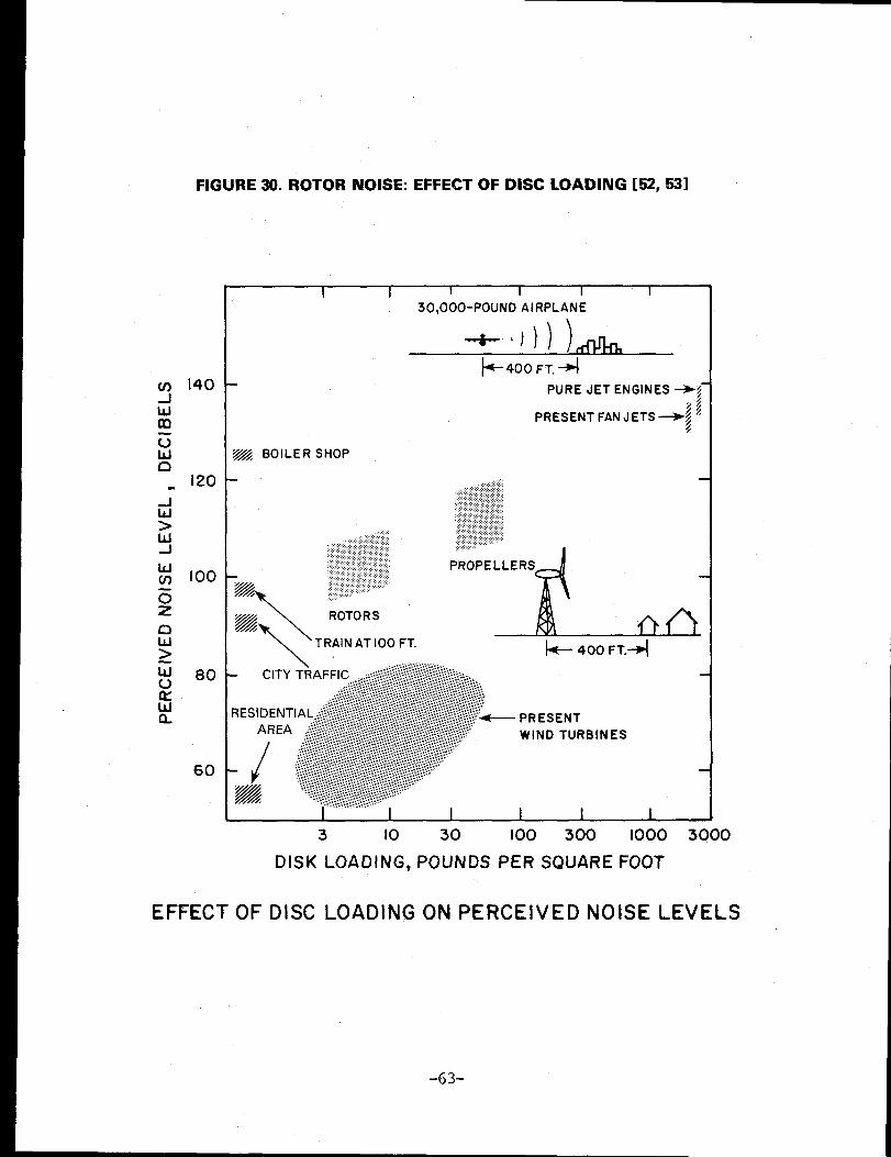
FIGURE 30. ROTOR NOISE: EFFECT OF DISC LOADING [52, 531
20
60
1
30,000-POUND AIRPLANE
~400FT.~
PURE JET ENGINES +;-
~~, BOILER SHOP
@\
ROTORS
\TRAIN AT 100 FT.
3 10 30 I00 300 1000 3000
DISK LOADING, POUNDS PER SQUARE FOOT
EFFECT OF DISC LOADING ON PERCEIVED NOISE LEVELS
-63-

turbine noise at the higher discloadings appears to be largelymasked by the ambient wind noiseitself.
We caution that these windturbine noise data are onlyapproximate and the results remaininconclusive. More acoustic testsare necessary before the noiseboundaries can be refined. Tipnoise is one of the first measurableenvironmental effects of windturbines, and prediction analysismust be developed early in order tosatisfy siting constraints.
The aeroacoustic predictioncodes have been extensivelydeveloped for the very generalrotorcraft cases. The capability topredict aerodynamic noise is,therefore, well in hand providedthe unsteady airloads can bedetermined. For wind turbines, thetechnology need is to provide theseunsteady loads to the predictionprograms. Additionally, new noisefield (pattern) descriptors, and“quality” parameters will likely beneeded, since perceived noise hasalways been a partly subjectivestudy (e.g., pulsed vs. continuous)[54].
ROTOR SIZE, PRODUCTIVITY,AND ECONOMY OF SCALE
An aerodynamic economy ofscale is possible with larger windturbine rotors. Large turbines aremore land efficient (see Figure 31[54]), are higher in the atmosphericboundary layer thus are usuallysubject to higher winds, and havelarger blade chords leading topotentially more desirable Reynoldsnumbers and a higher lift/dragratio. As a result, specific outputper swept area can be expected toincrease with rotor diameter. This
trend is shown in Figure 32,which presents the calculationscompiled by le Gourieres [55] anda number of other turbines. Thetheoretical annual output wasestimated by assuming a Weibullwind speed distribution with anannual average of 6 m./sec. (13.4MPH) 10 meter height and usingthe 1/7 power law for hub heightscaling. The curve shows esti-mated KWh/square foot of rotorarea/year vs. rotor diameter forwind turbines from 6 feet (1.8meters) to 329 feet (100 meters)in diameteq these are also listedin Figure 33.
At the lower diameters, thebulk of the machines follow aclear economy of scale. However,this is not a clear cut trend asevidenced by the outlying turbines.
Also, the curve is misleading,since the ability to produce energyincreases as the square of thediameter. Therefore, a truercomparison is a plot of specificoutput vs. rotor area, Figure 34.By looking at this graph andconsidering the outliers, it is clearthat the economy of scale argu-ment is not simple. If there wereno influence of size on economy,this plot ‘would show a horizontalline.
Figure 35 is a pictorial repre-sentation of the aerodynamiceffects which change the straight‘line ideal, and the direction oftheir expected effect, for largewind turbine rotors (200 ft. [61meters] diameter and larger). TheReynolds number, wind shear, andwind turbulence effects are shownschematically. Another beneficialeffect is the lower rotor soliditylikely with large rotors, and theresulting lower disk loading neces-sary to produce the same torque,
-64-

FIGURE 31. ECONOMY OF SCALE LAND USE EFFICIENCY AND PROFILE EFFECT [54]
SPECIFIC ANNUAL ENERGY PERROTOR DISC AREA, Eyr, ~p= f (H)
HUB HEIGHT, H (actual WECS output)200
I I oH*lmreI 1
L--P-Lower ‘ 1
limit ~practical
$;
100 4’
iInferior
inland sites
--L!--o bbo Soo 1000 1s00 MJxoo
SPECIFIC ANNUAL ENERGY . Eyr, sp, kWh/m2. Year
‘-z”’@m 7 + +GROUP STATION A17EA5 [WEpA ] FOR IGO MWNEAR COASTAL SITES : CLASS WEC-3 }
1],-~:~;s -+.--. .. ..-+-+-., .!.
-+-+-., .!.. . ..L -
%0=U.:----------+-:+::+:~:,! .,.
+:~;
x;?;:: :~e~:,..!.!.:.
;~;~~x; 2 :$8;:.........-+-+-●---.!.,.,.,. -+-+--t-?-*-,-......... 5.524:;:-+-+-+.+- ● ,.$..........+.+-?-,- -+-+-..........,-+-,.,..1.67~~:......!.
TOTALOUTPUT
Effect of WECS.Unit Size,P = 1-10 MW,on Group Station Land Area.PreliminaryTrend Estimate for Example-100 MWGroup Station
-65-

FIGURE 32. SPECIFIC PRODUCTIVITY VS. ROTOR DIAMETER
160
QCARTER 250
MOD IQWTS 4 (MAGLARP)
A
“ 0“/
6ROWIAN
-f
MOD 24 b
/
/&GOTLAND
/
NIBE
b/
/5-YEAR PLAN
TECHNICAL GOALS [11
MOD OAQ /
/
ESI 80U /
/O-DWT\VOLUND
CART~R 25 /w
/
ICURRENT
I / TECHNOLOGY [11
NORDTANK .f
J&40 ~ &WINDMATIC, so
ENAG ~ t yvESTASAEROWATT
SENCENBAUGHPOULSEN
20 t%KURIANT
~/DUN! ::~Hw’ND’plNsON
NEBJERG
I‘WINCO
o ~~L50 100 150 200 250 :300
DIAMETER (FT)
-66-
.

FIGURE 33. WIND TURBINE ENERGY PRODUCTIVITY (ESTIMATED) [55]
DIAMETER PRODUCTIVITY AREA SPECIFIC OUTPUT
11.8
13.5
16.4
16.4
30.2
19.7
33
36
36
39.4
39.4
43
49
65
80
95
125
135
200
246
256
300
329
TURBINE . m ft. Kw KWh\yr. ft. KWh\ft -’yrWINCO 1.8 6 0.2 300 28 10.7
SENCENBAUGH 3.6
DUNLITE 4.1
NORTH WIND 5
PINSON 5
AEROWATT 9.2
ENAG 6
CARTER 25
KURIANT
NORDTANK
WI17DMATIC
SONEBJERG
U. POULSEN
VESTAS
CARTER 250
ESI 80
VOLUND/DWT
MOD-OA
NIBE
MOD1
10
10.9
11
12
12
13
15
20
24.4
29
38
41
61
GOTLAND 75
WTS 4 78
MOD 2 91.5
GROWIAN 100.4
1.0
2
2
5
4.1
6
25
15
7.5/22
30
45
5.5/30
5/45
250
260
260
200
630
2000
2000
3000
2500
3000
2,500
3,000
5,000
5,000
20,000
10,000
55,000
28,000
30,000
45,000
45,000
40,000
60,000
550,000
400,000
500,000
1,200,000
1,500,000
5,000,000
6,000,000
8,000,000
10,000,000
12,000,000
109
143
211
211
716
305
855
1018
1018
1219
1219
1452
1886
3318
5025
7088
12272
14314
31416
47529
51472
70686
85012
22.9
21
23.7
23.7
27.9
32.8
64
27.5
29.5
36.9
36.9
27.5
31.8
166
79.6
70.5
97.8
104.8
159
126.2
155.4
141.2
141.2
-67-
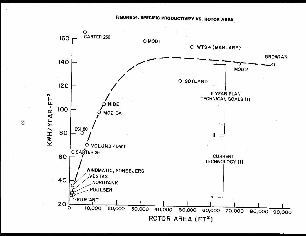
160
140
120
OJ
1-IA
& 100
60
40
FIGURE 34. SPECIFIC PRODUCTIVITY VS. ROTOR AREA
_ %WER 2500 MOD I
O WTS4 (MAGLARP)
GROWIAN
/-~—~~——
/
~m—~
1
~oMOD 2
/
/
0 GOTLAND
/5-YEAR PLAN
TECHNICAL GOALS [11
/’ NIBE
O MOD OA/
ESI 80 /-“-o--I -1
I~ VOLUNDi D”wT
ICA~’TER 25 ICURRENT
/TECHNOLOGY [11
I WINDMATIC, SONEBJERG
yVESTAS
&
NOR DTANKp~uL~EN
I ‘KU RIANT-
200 I 1 1 I 1 I I 110,000 20,000 30,000 40,000 S0,000 60,000 70,000 80,000 90,000
ROTOR AREA (FT2)
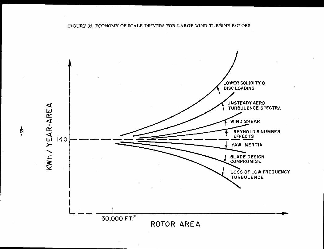
auClz
II
FIGURE 35. ECONOMY OF SCALE DRIVERS FOR LARGE WIND TURBINE ROTORS
—— —
LOWER SOLIDITY BIDISC LOADING
UNSTEADY AEROTURBULENCE SPECTRA
WIND SHEAR
REYNOLDS NUMBER
—— —. .— —. —— .—
YAW INERTIA
BLADE DESIGNCOMPROMISE
LOSS OF LOW FREQUENCYTURBULENCE
L —— I30,000 FT.*
ROTOR AREA
called the “CT/sigma effect”.Stated another way, a low-solidity,high tip speed ratio wind turbinehas a higher usable powercoefficient (efficiency) and operatesat lower average angles of attack.
Effects which could degrade theeconomy of large scale performanceare higher yaw inertia off-tracking, blade aerodynamiccompromise due to structuralrequirements, and the loss oflow-frequency “capturable energy”wind fluctuations. Clearly, moreneeds to be known about theunsteady performance of the rotorsand the representation of theunsteady inflow, before a definitiveconclusion can be made aboutaerodynamic economy of scale ofwind turbines.
VARIABLE SPEED ROTORS
A variable speed rotor whichoperates at constant tip speed ratiois attractive. Its most significantadvantage is that the rotoroperates at constant power co-efficient when it is at constant tipspeed ratio, and this can bedesigned to be the maximum powercoefficient (rotor efficiency) forthe rising power range (region 2),and steadily lower power coeffi-cients for the load control range(region 3; see Fig. 17). Additionally,the variable speed rotor uses aconstant pitch angle to maintain aconstant power coefficient, so nopitch change is required.
Another advantage of a constanttip-speed ratio rotor, but onewhich is not so easily quantified, isthe equilibrium of operation.Simply stated, the aerodynamic andinertial rotor blade loads are inbalance for all inflow wind speeds.This can be seen by referring toFigure 26. As wind speed
increases, RPM increasesproportionally; aerodynamic loadsincluding rotor thrust and torqueincrease as the square of windspeed, and the offsetting inertialcentrifugal forces balance sincethey increase as the square ofRPM as well. Therefore, theaverage coning angle of a constanttip-speed ratio turbine is constant.It is not clear what performanceimprovements this could eventuallybring, but potentially beneficialaspects are:
1.
2.
3.
4.
As
The variable speed, con,-:stant tip speed ratiooperation is a true “point(design”, with all f luctu -:itions occurring around thesame, specified operationalcharacteristic.
The wake state and loaclequilibrium are constant.
Aerodynamic equilibrium ismaintained; therefore, anybeneficial unsteadyaerodynamic conditionwhich is specified, such asal standing tip vortex, willbe maintained.
By allowing a utilitygrid-connected turbine toc~perate at variable speed,the rotor is effectivelycle-coupled from the load,and is therefore less vulne-rable to power griddiscontinuities, and hasbeneficial aerodynamicdamping to variations intlhe rotor inflow.
rotor size increases thesearguments continue to hold ident-ically, therefore, tip speed ratio isa powerful scaling parameter. Toa first approximation, the tipspeed ratio is just proportional to
-70-

the angle of attack of the turbinedecreasing the tip speed ratiouniformly increases angle of attack[56], and vice-vers& this also canbe seen by referring to Figure 26.The size limitation of variablespeed turbines is apparentlystructural, since gravity loads donot scale or stay in equilibrium asdo aerodynamic and inertial loads[57].
Therefore, we perceive a needfor the study of constant tip speedratio turbines, particularly underunsteady conditions.
ADVANCED CONCEPTS
There is potential for largeimprovement in specific output ofwind turbine rotors by usingadvanced aerodynamic concepts,An example is the shrouded turbine,Figure 36. Possible aerodynamicbenefits which could be achievedare increased mass flow thuspower augmentation; lowersensitivity to yaw off-tracking;lower fluctuations in torque due todamping of inflowq and higherturbine speed and efficiency.Whether these benefits wouldoutweigh the disadvantages ofcomplexity, cost and weight remainsa question for design study. Thisstudy cannot be effectivelyaccomplished until the unsteadyinflow has been sufficientlydescribed, but the other designtools are well in hand. Forexample, a duct lift coefficient of3.0, which is achievable withstandard leading-edge devices suchas triple-slotted or Fowler flaps,will theoretically give a power fluxincrease by a factor of five (seeFigures 37 [15] and 38 [58]).
The ducted turbine is just oneexample of a family of advancedconcepts, all of which have the
potential to exceed the Betz limiton power coefficient (0.5926)based on rotor swept area; this isgenerally held to be the maximumfor conventional HAWT rotors [15,55]. The physical interpretationof the Betz limit for VAWT is notclear, and this is complicated bythe added unsteadiness of theaffected streamtube and turbinewake.
Another example is the tipvane, Figure 39 [59]. Powercoefficients based on rotor sweptarea above 2.0 have been demon-strated in wind-tunnel tests. Theaerodynamic mechanism appears tobe a standing vortex ring producedby winglets at the tips, sopositioned that they induce aconvecting pair of tip vortices inthe wake flow which interfereconstructively to produce a weakaerodynamic equivalent of a solidduct. Increased mass flow thenresults as long as the geometry ismaintained. The wake state andgeometry must be preserved byoperating at constant tip speedratio, and the inflow must besteady. Substantial augmentationhas not yet been achieved in fieldtests [60], but we believe it islikely that it eventually will bedemonstrated. Again the researchneed is for proper unsteady flowdescription and testing.
Other advanced concepts whichmight obtain higher performancethan conventional systems arevariable geometry rotors, includingvariable twist, variable diameter,and variable chord.
The potential improvementsoffered by these concepts aretempting to exploit, but mucheffort may be wasted if realistic,unsteady conditions are notconsidered at the very outset of a
-71-

FIGURE 36. SHROUDED WIND TURBINE ROTOR
CIRCULATION DUE TO SHROUD
u
/ -H /--
//
//
0/
———_ 0-
}
‘FORCE ACTINGON SHROUD
—.— . .—. —. —. —~--. —” —.—. —
-72-

FIGURE 37. AVERAGE MASS FLOW INCREASE THROUGH AN ANNULAR WING [15]
,,
K)
‘1
c’F“
0.I
,, w .—-+1 I
O.O1110 /2 /4 ~’6 ,18 *10 J2 J4. . . . , ● . .VELOCITY INCREASE THROUGH RING U@J
-73-

FIGURE 38. HIGH SECTION LIST COEFFICIENTS FROM FLAPS [58]
E3asic section
Plain flap Split flap
@zzzzzz--=-
\
Slotted flap Fowler flap
---
~1
Effect on section lift and dragcharacteristics of a 25% chord
flap deflected 30°
3.0Fowler
y
Slotted
Split
/
/-,/ Plain
/
/
Basic
section
-
3.01-
–10–5051015 200 0.05
- Basic
eection
Fowler
0.10 0.15
Section angle of attack Section drag coefficienta (deg) cd
-74-

FIGURE 39. TIP VANE ROTOR
—
[59]
TILT-ANGLE V\.I TIPVAhIE
-75-

development program. The tech-nology base is very embryonic forthese rotors as contrasted with themore conventional HAWT rotors oreven the existing VAWT rotors.
NEW DESCRIPTORS
Non-dimensional parametershave been valuable in the designdevelopment of aircraft and rotor-craft. The most valuable use ofnon-dimensional aerodynamic quan-tities has been in the scaling andsimilarity studies necessary forsmall-scale controlled field andwind tunnel testing. However,these parameters are also useful incomparing various design conceptsfor performance and reliability.
Aerodynamic research has tendedto use these traditional non-dimen-sional quantities to frame itsplanning and judge its own pro-gress. Some are general, and arepresently used for wind turbines aswell (e.g., Reynolds number, Machnumber). Wind turbine studies havealso generated some quantitiesspecific to wind turbines, forexample, thrust coefficient, powercoefficient, and tip speed ratio.(Refer to Appendix 2 for the
difference between the windturbine and helicopter definitions.)
Additional descriptors need tobe adopted which are relevant towind turbines, both in the aero-dynamics and in the systemanalysis. Some possibilities are:a plant/capacity factor of therotor thalt would be useful tocompare with other competingpower plants [61]; a non-dimensional installed torque vs.produce(i torque, to be used forthe comparison of differentturbines with varying installedpower-to-rotor size ratios; and adesign rotor “lift coefficient” thatincludes the expected moments ofinflow fluctuation around theequilibrium condition, to judge thepercentage of off-design availa-bility.
We believe that the search forthese should properly begin in theexamination of test data, wherevarious trials can be made todiscover generality, and in basicstudies olf unsteady airfoilbehavior and unsteady rotorinflow. An example is the reducedfrequency, which is one of thedriving (but maybe not the mostsignificant) conditions for dynamicstall.


CHAPTER8. RECOMMENDED DOE WIND TURBINEUNSTEADY AERODYNAMICS R&ll PROGRAM
PRESENT FEDERAL WIND ENERGYPROGRAM
This Chapter outlines aspects ofa national R&D program for implem-enting the wind turbine unsteadyaerodynamics research needs putforth in this Report. This effortmust and can occur within thepresent framework of the currentDOE wind energy program, which isdescribed below.
A description of the presentfederal wind energy program isquoted below from the Five YearWind Energy Program Plan [1]. Thethree major parts to the presentDOE wind energy program are (1)sponsor basic research, (2) conductresearch on advanced componentsand systems, and (3) transfer theresearch results to industry
“Federal policy on energy researchand development (R&D) is to sponsoractivities that are unlikely to becarried out by private industrybecause of the technical and financialrisks involved. Accordingly, thegoal of the Federal Wind EnergyProgram is to conduct research toestablish a technology base and tosupport industry in confirming theviability of wind energy as anenergy supply alternative. Thisresearch will complement and supportprivate sector efforts to developwind systems that are safe, reliable,and cost-effective.
The Federal Wind Energy Program’sR&D strategy has three main elements.First, the program will sponsorbasic research on the science ofwind turbine dynamics. This researchmust be conducted to understandthe random nature of the wind
resource itself, its complex inter-action with the wind turbine, andthe effects of this interaction cmperformance and reliability. Second,advanced components and systemsresearch will be conducted. Thisresearch will establish the technologyfor advanced components such ashigh-performance airfoils designedspecifically for wind turbine operation.The program will verify researchresults through testing on DOEtest beds and through cooperativefield test programs on commercialmachines. Finally, the programwill transfer the research resultsto industry for use in developingcost-effective wind turbines.
Successful implementation ofthis R&D strategy requires aneffective partnership betweengovernment and industry. Thefederal role in the development ofwind energy technology mustcomplennent and support industryresearch and development. FecleralR&D activities are aimed at support-ing the general advancement ofthe technology by providing thescientific knowledge that industrycan then apply in the developmentof improved machines. To ensurethe efficient use of public re-sources, the federal governmentfocuses its efforts on activitiesthat industry is not expected toundertake on its own because ofthe cost, risks, or developmenttime involved. In general, theprogram~ takes primary responsibilityfor worlking with industry to determinelong-term research needs, sponsoringthe research needed to addressthose priorities, and disseminatingresearch results. The federalprogram then relies upon industryto apply the technology base in
-78-

order to improve the cost, performance,and lifetime of future wind machines[1].”
The current DOE plan thusplaces increased emphasis on animproved understanding of the basicphysical phenomena involved inconverting the wind to useful energy.The (draft) November 1985 RevisedComprehensive Program ManagementPlan [62] goes further in this regardto establish objectives in specificareas in which technical advancesare required
o
0
0
0
“Improve the understanding offundamental sources of windvariabilityy--local windflowvariability and shear, and turbine-to-turbine interactions.
“Increase basic understandingof the interactions betweenwind input and structural responseand the resulting effects onperformance and loads.
“Investigate, through generic,proof -of -concept activities, thepotential for improved performanceusing advanced components andsubsystems.
“Develop an advancedmulti-megawatt wind turbine[62].”
ROLE OF PRESENT AERODYNAMICSTECHNICAL ASSESSMENT
The wind turbine aerodynamicsR&D programs recommended by thePanel in this Technical Assessmentaddress the first two objectivesstated above. The specific sub-problems that properly delineatethe two objectives are the researchneeds recommended by the Panel inChapter 4
Unsteady Aerodynamics
Dynamic Stall Understanding--
Develop an understandingof the 2-D and 3-D hysteresiseffects of dynamic stall.
Testing Methodology for UnsteadyFlow--
Stimulate complex unsteadyflows in wind tunnel andtotal system (field) tests inorder to exploit dynamicstall effects.
Airfoil Development Studies forUnsteady Flow--
Initiate a design processwhich will yield airfoilsspecifically suited for unsteadyflow, and which considersthe significance ofi
o dynamic stall repeat-ability and insensivity
o airfoil roughness
o delayed stall and softstall
o performance and prediction
o rotor stability, and
o airfoil control devices.
Wind Inflow Models: The De-velopment of Aerometeorology
Establish a new study termedaerometeorology, which willattempt to develop realisticinflow models for theassessment of unsteadyeffects, including thespecific cases of
-79-

o
0
0
0
Interface
unsteady, uniform inflow--or representation of theuniform gust fron~
unsteady nonuniform inflow--or representation of frozenturbulence;
steady, nonuniform inflow--or representation of steadyinflow fronts; and
stochastic inflow--or representation of inflowin the frequency/wavenumber domain.
Topics
Aeroelasticity--
Develop a methodologydefining the unsteadyairloads which must beincluded in the struc-tural dynamic models.
Control Systems--
Investigate the per-
for
formance and reliabilitybenefits to be obtainedwith external control actions,such as ailerons, in steadyand unsteady flow.
Wake Model InterferenceDevelopment--
Develop and verify amodel for the structureand decay of the unsteadywind turbine rotor wake.
Component Wake InterferenceDevelopment--
Develop and verify modelsfor the structure anddecay of the unsteadywakes caused by turbinecomponents such as towers.
-80-
Shutdown (Emergency) Systems- -
Develop an understandingof the behavior of airfoilsunder extreme conditions,and at very high angles ofattack, such as a movingaileron in separated flow.
In addition, further steady-state aerc~dynamics studies shouldbe continued in order to provide asuitable data base for the aboveinvestigations and lend insightinto the new physical and mathe-matical models and design toolswhich must be used.
Steady Aerodynamics
Three-Dimensional Flow--
Assess the degree of 3-Dor spanwise flow whichoccurs under typical conditions,and relate that to the inflowand turbine wake geometry.
Wake Modeling--
Develop and verify a modelof the turbine vortex wakegeometry suitable for performa-nce and stability studies.
Effect of Roughness inSteady State--
Develop an understandingof environmentally-inducedairfoil surface roughness onairfoil transition and separationin steady flow.
Airfoil Mechanisms--
Investigate the effect ofairfoil mechanisms, such asvortex generators, on delayingturbine rotor stall andseparation.

Two-DimensionalDevelopment--
Airfoil
Develop a verified method-ology for tailored windturbine airfoil design insteady state to establish adatabase for future unsteadyairfoil design.
Testing Methodology forSteady Flow--
Continue steady-statewind turbine testing inwind tunnels and in thefield, to acquire long-term performance dataand to investigate thebenefits of new airfoils.
The Technical Assessment hasthus provided the proper focusfor specific tasks to meet theDOE objectives of improving theunderstanding of fundamental sourcesof wind variability, and increasingthe basic understanding of theinteractions between the wind, theair flow response, and the performanceof wind energy systems. Further,the recommended work will eventuallyresult in adequate and confidentdesign tools for configuration studies,thus permitting major improvementsin productivity and reliability offuture wind energy systems.
DIFFICULTY IN ESTABLISHINGSPECIFIC TASK GOALS
The specific goals of the in-dividual investigations cannot andshouId not be described in detailhere. Additional work must bedone. The most that can be saidat this time is that an effectiveplan will incorporate the followingaspects, which are described morefully in Chapter 5:
00
0
0
0
Stressing basic research,Striving for better understandingof the physical phenomena,Maintaining a patient, long-termattitude,Keeping distance from the commer-cial uses, andCoordinating knowledge fromdisciplines related to aerociy-namics and affecting wind turbinedesign.
MANAGEMENT OF INVESTIGATIONS
The bulk of the R&D investigationsshould ideally occur at a facility- ~.which would include both analyticaland experimental (testing) studies.Subproblems properly defined bythe overall R&D plan could besubcontracted to capable outsidecontractors, but their supervision,as well as the inhouse R&D manage-ment, should be kept centralized.If the management planning is doneby incorporating the aspects describedabove, there should be a minimumof program competition and conflictof interest since the scientificcenter of expertise for each taskwill be obvious in each case.
The reporting would be verticalin all cases; that is, a clear centraladministrative and decision-makingoffice would control all aspects ofthe wind turbine program.
The experimental facility forfield- and wind-tunnel testingshould also ideally be located nearthe analysis facility to permitfrequent and informal communicationamong researchers. A wide rangeof engineering and scientific disci-plines characteristic of basic researchwould also be required.
Inhouse funding and technicalstaffing should be large enough to
-81-
allow a wide degree of investigativefreedom, but care should be takento discourage proprietary, closed,or near-term commercializableprojects. In summary the characteristicsof the recommended R&D managementwould be
1. Vertical reporting andaccountability.
2. Close proximity of theoreticaland experimental efforts.
3. Close cooperation of testand analysis researchers.
4. Central accountability ofoutside subcontractors.
5. Scheduled central review ofR&D goals and progress.
6. Scheduled frequent reportingof results to the technical communityand industry.
7. Particular effort to keep awide range of technical disciplinesinhouse.
8. Maintenance of distance fromthe commercial interests, but encour-agement of the cooperation of industryR&D efforts.
FACILITY
The best facility would ideallybe a first-rate wind tunnel and afield test installation in closeproximity. The wind tunnel wouldhave unsteady flow andturbulence-generating capability.The field installation would
have a sophisticated, permanentspatial array of sensors to recordthe atmospheric inflow statistics.Instrumentation for the wind tunneland field site would be determinedso as tc! accurately and completelyrecord the variables needed to havegood experimental control and anaccurate frame of reference.
A sophisticated data-processingcenter would be required for bothinstallations to permit accuratestorage of data; real-time generationof turbulence statistics necessaryfor stochastic analysis; verificationof state-of-the-art analyticalcodes; building up of a field testdatabase for future retrieval; andmanipulation of large data sets,,
The field installation wouldhave rotors with full aerodynamicand dynamic instrumentation whichincludesc blade spanwise andchordwise pressure transducers;,blade strain transducers; rotorthrust and torque transducers;rotorblade motion and positionindicators; and flow visualizationcapability. Collective and cyclicpitch pc)sitioning and recordingwould be required also, with thenecessary frequency responsedetermined by the appropriateunsteady aerodynamics test plan.
Aware that the above will bevery difficult to achieve, thePanel recommends a next-bestapproach of subcontracting for thewind tunnel, and keeping the restof the effort together at a commonfacility.
-82-
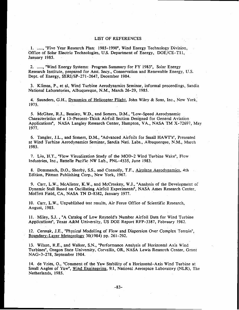
LIST OF REFERENCES
1. ...... “Five Year Research Plan 1985-1990”, Wind Energy Technology Division,Office of Solar Electric Technologies, U.S. Department of Energy, DOE/CE-Tl 1,January 1985.
2. ...... “Wind Energy Systems: Program Summary for FY 1983”, Solar EnergyResearch Institute, prepared for Asst. Secy., Conservation and Renewable Energy, U.S.Dept. of Energy, SERI/SP-271 -2647, December 1984.
3. Klimas, P., et al, Wind Turbine Aerodynamics Seminar, informal proceedings, SandiaNational Laboratories, Albuquerque, N.M., March 26-29, 1985.
4. Saunders, G. H., Dvnamics of Helico~ter Flight, John Wiley & Sons, Inc., New York,1975.
5. ~cGhee, R.J., Beasley, W.D., and Somers, D.M., “Low-Speed AerodynamicCharacteristics of a 13-Percent-Thick Airfoil Section Designed for General AviationApplications”, NASA Langley Research Center, Hampton, VA., NASA TM X-72697, May1977.
6. Tangier, J.L., and Somers, D.M., “Advanced Airfoils for Small HAWT’S”, Presentedat Wind Turbine Aerodynamics Seminar, Sandia Natl. Labs., Albuquerque, N.M., March1985.
7. Liu, H.T., “Flow Visualization Study of the MOD-2 Wind Turbine Wake”, FlowIndustries, Inc., BattelIe Pacific NW Lab., PNL-4535, June 1983.
8. Dommasch, D.O., Sherby, S.S., and Connolly, T.F., Airrdane Aerodynamics, 4thEdition, Pitman Publishing Corp., New York, 1967.
9. Carr, L.W., McAlister, K.W., and McCroskey, W.J., “Analysis of the Development ofDynamic Stall Based on Oscillating Airfoil Experiments”, NASA Ames Research Center,Moffett Field, CA, NASA TN D-8382, January 1977.
10. Carr, L.W., Unpublished test results, Air Force Office of Scientific Research,August, 1985.
11. Miley, S.J. , “A Catalog of Low Reynold’s Number Airfoil Data for Wind TurbineApplications”, Texas A&M University, US DOE Report RFP-3387, February 1982.
12. Cermak, J.E., “Physical Modelling of Flow and Dispersion Over Complex Terrain”,Boundarv-Laver MeteorologyV 30(1984) pp. 261-292.
13. Wilson, R.E., and Walker, S.N., “Performance Analysis of Horizontal Axis WindTurbines”, Oregon State University, Corvallis, OR, NASA Lewis Research Center, GrantNAG-3-278, September 1984.
14. de Vries, O., “Comment of the Yaw Stability of a Horizontal-Axis Wind Turbine atSmall Angles of Yaw”, Wind Emzineering, 91, National Aerospace Laboratory (NLR), TheNetherlands, 1985.
-83-

15. de Vries, O., “Fluid Dynamic Aspects of Wind Energy Conversion”, AGARDographNo. 243, National Aerospace Laboratory (NLR), The Netherlands, 1979.
16. Lundsager, P., “On the Power Regulation of Small Wind Turbines Based onExperience with Small Danish Wind Turbines”, Riso National Laboratory, Denmark,pres. at 5th Biennial Wind Energy Conference, Washington, D.C., October 1981.
17. Montgomerie, B., “Unsteady Aerodynamics Applied to the Horizontal Axis WindTurbine Disk”, National Aeronautical Laboratory, Sweden, FFA Memo, November 29,1984.
18. Hirschbein, M.S., “Dynamics and Control of Large Horizontal-Axis AxisymmetricWind Turbines”, Ph.D. Thesis, Univ. of Delaware, University Microfilms 8006484, June,1979.
19. Ericsson, L.E., “Is Any Free Flight/Wind Tunnel Equivalence Concept Valid forUnsteady Viscous Flow?”, Lockheed Co. Inc., Sunnyvale, CA, Journal of Aircraft, Vol.22, No. 10, October 1985, also AIAA Paper 85-0378.
20. Drees, H.M., FloWind Corp., Private testimony to the Wind Turbine AssessmentPanel, Oakland, CA, August 1985.
21. Nelson, V. , Alternative Energy Institute, West Texas State Univ., Privatetestimony to the Wind Turbine Assessment Panel, Oakland, (CA, August 1985.
22. Payne, F.M., and Nelson, R.C., “Aerodynamic Characteristics of An Airfoil in aNonuniform Wind Profile”, Univ. of Notre Dame, Notre Dame, IN, Journal of Airc@t,Vol. 22, No. 1, January 1985, also AIAA Paper 82-0214.
23. Mueller, T.T., “The Influence of Laminar Separation and Transition on LowReynolds Number Airfoil Hysteresis”, Univ. of Notre Dame, Notre Dame, IN, Journal ofAircraft, Vol. 22, No. 9, September 1985, also AIAA Paper 84-1617.
24. Staples, D.L., and Cao, H.V., “Summary of Wind Tunnel Results for the NACA23024 Airfoil”, Wichita St. Univ. Wichita, KS, prepared for NASA-Lewis Res. Center,Grant No. NSG-3277, WER-36, September 1985.
25. Akins, R,E., “Pressure Distributions on an Operating VAWT”, Presented at WindTurbine Aerodynamics Seminar, Sandia Natl. Labs., March 1.985.
26. .....Private comments shared, Windfarm Site Visits, Wind Turbine Assessment PanelMeeting, Oakland, CA, August 1985.
27. Bundas, D. and Dugundji, J., “Some Experiments on Yaw Stability of Wind Turbineswith Various Coning Angles”, MIT ASRL Report TR 197-2, July 1981.
28. Connell, J.R., and George, R.L., “Scaling Wind Characteristics for Designing Smalland Large Wind Turbines”, Battelle Pacific NW Lab., Presented at 6th Biennial WindEnergy Conference and Workshop, Minneapolis, MN, June 1-3, 1983.
-84-

29. Hausfeld, T.E., and Hansen, A.C., “A Systematic Approach to Using theMethod-of -Bins”, U.S. Dept. of Energy, Small Wind Turbine Test Center, Rocky Flats,CO, 1983.
30. Lundsager, P., Petersen, H., and Frandsen, S., “The Dynamic Behavior of theStall-Regulated Nibe A Wind Turbine Measurements and a Model for Stall-InducedVibrations”, Riso Report M-2253, Riso National Laboratory, Denmark, November 1981.
31. Eggleston, D.M., and Stoddard, F.S., ~, VanNostrand Reinhold, New York, to be published.
32. Althaus, D., “Polarenmussungen An Den Profilen Wortmann FX 84-W’, Univ. ofStuttgart, FRG, Presented at 12th Meeting of Aerodynamic Experts for CalculationMethods for WECS, Technical Univ. of Denmark, International Energy Agency IEA,ISSN 0343-7639, March 1985.
33. Wentz, W., and Snyder, M., “Wind Tunnel Tests of Spoilers and Ailerons for WindTurbine Power Control and Braking”, Presented at Wind Turbine Aerodynamics Seminar,Sandia Natl. Labs., Albuquerque, NM, March 1985.
34. Vermeulen, P., “A Wind Tunnel Study of the Wake of a Horizontal-Axis WindTurbine”, Netherlands Organization for Applied Sciences, Research TNO Report No.78-09674, September 1978.
35, Lissaman, P.B.S., Gyatt, G.W., and Zalay, A.D., “Numeric Modeling SensitivityAnalysis of the Performance of Wind Turbine Arrays”, AeroVironment, Inc., Pasadena,CA, prepared for Battelle Pacific NW Lab., PNL-4183, June 1982.
36. Vermeulen, P., “An Experimental Analysis of Wind Turbine Wakes”, Presented at3rd International Symposium on Wind Energy Systems, Copenhagen, Denmark, 1980.
37. Murtha, S.J., “Loads and Fatigue Evaluation of the Hamilton Standard WTS-4 WindTurbine”, Presented at WindPower ’85, Conference of the American Wind EnergyAssociation and U.S. Dept. of Energy, San Francisco, August 27-30, 1985.
38. Ardebili, M., Hazaraka, B.K., and Raj, R., “The Separated and Non-separated AirfoilWake Behavior in the Presence of Free Stream Turbulencew, C.C.N.Y., New York, Pres.at 3rd AppIied Aerodynamics Conference, Colorado Springs, CO, October 14-16, 1985,AIAA Paper 85-5027.
39. Wentz, W., “Effects of Spanwise Flow on the Section Properties of a StalledAirfoil”, Presented at Wind Turbine Aerodynamics Seminar, Sandia Natl. Labs.,Albuquerque, NM, March 1985.
40. Klimas, P.C., “A Spanwise Flow Estimation Model”, Presented at Wind TurbineAerodynamics Seminar, Sandia NatI. Labs., Albuquerque, NM, March 1985.
41. Marchman, J.F., Abtant, A.A., Sumantrau, V., and Sun, Z., “Effects of Aspect Ratioon Stall Hysteresis for the Wortmann Airfoil”, V.P.I., Blacksburg, VA, AIAA Paper 85-1770, October 1985.
-85-

42. Im, B.J., “Advanced Method for Modeling Airfoil Surfidce and Wake Panels inUnsteady Flow”, Texas Tech University, Presented at Wind Turbine AerodynamicsSeminar, Sandia Natl. Labs., Albuquerque, NM, March 198!;.
43. Miller, R.H., et al, “Free Wake Analysis of Wind Turbine Aerodynamics”, VolumeVIII, MIT ASRL TR- 184-14, “Wind Energy Conversion”, Prepared for U.S. Dept. ofEnergy, Sept. 1978.
44. Kocurek, J.D., “Lifting Surface Performance Analysis for Wind Energy ConversionSystem Rotors”, Presented at Wind Turbine Aerodynamics Seminar, Sandia Natl. Labs.,Albuquerque, NM, March 1985.
45. Miller, G.E., “The Effect of Vortex Generators on the Section Properties of aModified NACA 23024 Airfoil”, Boeing Aerospace Company, Presented at Wind TurbineAerodynamics Seminar, Sandia Natl. Labs., Albuquerque, NM, March 1985.
46. Berg, D.E., “An Improved Double-Multiple Streamtube Model for the Darrieus-TypeVertical Axis Wind Turbine”, Presented at 6th Biennial Wind Energy Conference andWorkshop, U.S. Dept. of Energy, Minneapolis, MN, June 1-3, 1983.
47. Cheney, M.C., Windtech, Inc., Private comments at the Wind Turbine AssessmentPanel Meeting, Oakland, CA, August 1985.
48. Powell, D.C., and Connell, J.R., “Definition of Gust Model Concepts and Review ofGust ModeIs”, Battelle Pacific NW Laboratory, PNL-3 138, June 1980.
49. Panofsky, H.A., and Dutton, J.A., Atmos~heric Turbule~, John Wiley & Sons, NewYork, 1984.
50. Hoerner, S.F., Fluid-Dynamic Drag, Published by the author, 1958.
51. Rawson, K.J., and Tupper, E.C., Basic Shit) Theorv, American Elsevier PublishingCo., Inc., New York, 1968.
52. Lindenbaum, B.L., et al, “Beyond The Horizon Flight in the Atmosphere,1975-1985”, Volume 111,“Vertical Takeoff and Landing”, USAF Air Force SystemsCommand, AFSC Task Force, January 1967.
53. Martinez, R., Widnall, S.E., and Harris, W.L,, “Predictions of Low Frequency andImpulsive Sound Radiation from Horizontal Axis Wind Turbines”, NASA CR 2185,February 1981.
54. Ljungstrom, O., “Large Scale Wind Energy Conversion System (WECS) Design andInstallation as Affected by Site Wind Energy Characteristics, Grouping Arrangement,,and Social Acceptance”, Wind Engineering 1:1, 1977.
I55. Le Gourieres, D., Wind Power Plants: Theorv and Desi~g, Pergamon Press, Oxford,UK, 1982.
56. Rasmussen, F., “Blade and Rotor Loads for Vestas 15“, Riso-M-2402, Test Plant forSmall Windmills, Riso National Laboratory, Denmark, June 1983. I
-86-

57. Ormiston, R. A., “Rotor Dynamic Considerations for Large Wind Power GeneratorSystems”, Presented at 1st Workshop Proceedings, Wind Energy Conversion Systems,National Science Foundation/RANN, Washington, D.C., June 11-13, 1973.
58. Hurt, H.H., Aerodynamics for Naval Aviators, Navair 00-80T-80, Revised January1965.
59. van Holten, T., “Performance Analysis of a Windmill with Increased Power Outputdue to Tipvane Induced Diffusion of the Airstream”, Memorandum M-224, TechnischeHogeschool Delft, The Netherlands, November 1974.
60. Lissaman, P.B.S., Zalay, A.D., and Hibbs, B.H., “Advanced and Innovative WindEnergy Concept Development Dynamic Inducer Systems”, Executive Summary,AeroVironment, Pasadena, CA, May 1981.
61. Steeley, W., Hillesland, T., Ilyin, M, and Smith, D., “PGE’s Wind Energy ProgramResults”, Pacific Gas and Electric Company, Presented at Windpower ’85, Conference ofAmerican Wind Energy Association and U.S. Dept. of Energy, San Francisco, CA,August27-30, 1985.
62. ...... “Federal Wind Energy Program, 5th Annual Revised Comprehensive ProgramManagement Plan”, draft November 1985, Office of Solar Electric Technologies,Conservation and Renewable Energy, US Dept. of Energy, Washington, DC.
63. Stoddard, F.S., “Momentum Theory and F1OWStates for windmills”, mTechnolo~v Journal, 1:1, Spring 1977.
64. Walker, S.N., and Wilson, R.E., “Performance Analysis Program for Propeller TypeWind Turbines”, Oregon State University, Corvallis, OR, October 1976.
65. Wilson, R.E., and Lissaman, P.B.S., “Applied Aerodynamics of Wind PowerMachines”, Oregon State University, Corvallis, OR, NTIS PB 238594, July 1974.
66. Dugundji, J., and Wendell, J.H., “General Review of the MOSTAS Computer Codefor Wind Turbines”, MIT ASRL Report 197-1, NASA Lewis Research Center, NASACR-165385, June 1981.
67. McCormick, B.W., Aerodynamics of V/STOL Flight, Academic Press, New York,1967.
68. Mehta, U. B., “Dynamic Stall of an Oscillating Airfoil”, Proceedings AGARD FluidDynamics Panel Symposium on Unsteady Aerodynamics, AGARD CPP-227, September1977.
69. Nielsen, P., et al, “Measurements on the Nibe Wind Turbines January 1980 toMarch 198l“, Research Assn. of the Danish Electricity Supply Undertakings, DEFUReport No. EEV 81-04, May 1981.
-87-

70. Cromack, D.E., et al, “Investigation of the Feasibility of Using Windpower forSpace Heating in Colder Climates”, Final Report, Energy Alternatives Program, Univ. ofMass., Amherst, MA, UM-WF-PR-78-5, July 1978.
71. Lynette, R., et al, “Wind Power Station~ 1984 Performance and Reliability”,Electric Power Research Institute, Palo Alto, CA, Res. Proj. 1996-2, Interim Report,January 1985.
72. Glasglow, J.C., Corrigan, R.D. and Miller, D.R., “The Effect of Yaw on HAWTLoading and Performance” NASA-Lewis Research Center, DOE/NASA/20320-35, NASATM-82778, presented at 5th Biennial Wind Workshop, Washington, D.C. October 5-7,1980.
-88-

APPENDIX 1. LIST OF REPORTS REVIEWED
1985
Hibbs, B.D., “HAWT Performance with Dynamic Stall”, AeroVironment, Inc., Pasadena,Calif., SERI, March 1985.
Swift, A.H.P., Editor, ‘Proceedings of Fourth ASME Wind Energy Symposium”, EighthAnnual Energy Sources Technology Conference and Exhibition, Dallas, Texas, Feb.17-21, 1985, American Society of Mechanical Engineers, 345 East 47th St., New York100170
Thresher, R.L., and Hershberg, E.L., “Development of an Analytical Model and Code forthe Flapping Response of a HAWT Rotor Blade”, Oregon State University, Corvallis,Oregon, SERI, February 1985.
Kelley, N.D., et al, “Acoustic Noise Associated with the MOD-1 Wind Turbine: ItsSource, Impact, and Control”, SERI/TR-635- 1166, February 1985.
1984:
Anon ......... “Wind Energy for a Developing World”, Wind Energy Program Office, U.S.DOE, International Trade Administration, U.S. Dept. of Commerce, and American WindEnergy Association, DOE/CE-T12, 1984.
Honey, W.E., Thresher, R.W., and Lin, S.R., “Atmospheric Turbulence Inputs forHorizontal Axis Wind Turbines”, Oregon State University, Corvallis, Oregon, SERI,—October 1984.
—
Wilson, R.E., and Walker, S.N., “Performance Analysis of Horizontal Axis WindTurbines”, Dept. of Mechanical Engineering, Oregon State Univ., Corvallis, Oregon,Sept. 1984; work performed for NASA/Lewis Research Center, Grant NAG-3-278.
Anon ...... “MOD-5A Wind Turbine Generator Program Design Report, Volumes I, II, andIII Executive Summary, Conceptual & Preliminary Design, and Final Design & SystemDescription”, General Electric Company, DOE/NASA/01 53-1,2, and 3, NASA CR-174734,5, & 6, 84AEPDO04, August 1984.
Miller, D.R., and Puthoff, R. L., “Aileron Controls for Wind Turbine Applications”,DOE/NASA/20320-60, NASA TM-86867, August 1984.
McCabe, T.F., “Analysis of Wind Energy Systems for Selected Electric Utilities”, SolarEnergy Research Institute, Golden, Colorado, SERI/TR-2379, July 1984.
Sullivan, T.L., “Effect of Vortex Generators on the Power Conversion Performance andStructural Dynamic Loads of the MOD-2 Wind Turbine”, NASA Lewis Research Center,DOE/NASA/20320-59, NASA TM-83680, June 1984.
Flaim, T., and Hock, S., “Wind Energy Systems for Electric Utilitiex A Synthesis ofValue Studies”, SERI, Golden, Colorado, SERI/STR-211 -2318, May 1984.
-89-
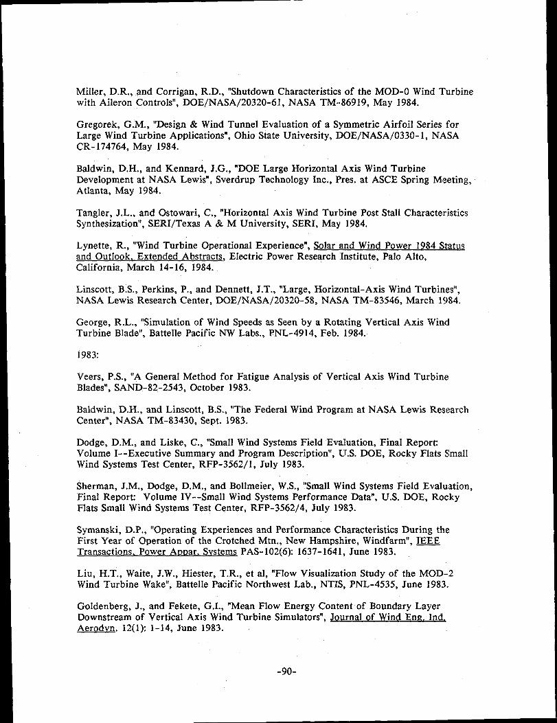
Miller, D.R., and Corrigan, R.D., “Shutdown Characteristics of the MOD-O Wind Turbinewith Aileron Controls”, DOE/NASA/20320-6 1, NASA TM--86919, May 1984.
Gregorek, G.M., “Design & Wind Tunnel Evaluation of a Symmetric Airfoil Series forLarge Wind Turbine Applications”, Ohio State University, DOE/NASA/0330- 1, NASACR- 174764, May 1984.
Baldwin, D.H., and Kennard, J.G., “DOE Large Horizontal Axis Wind TurbineDevelopment at NASA Lewis”, Sverdrup Technology Inc., I%es. at ASCE Spring Meeting,Atlanta, May 1984.
Tangier, J.L., and Ostowari, C., “Horizontal Axis Wind Turbine Post Stall CharacteristicsSynthesization”, SERI/Texas A & M University, SERI, May 1984.
Lynette, R., “Wind Turbine Operational Experience”, solar and Wind Power 1984 S@@and Outlook. Extended Abstracts, Electric Power Research institute, Palo Alto,California, March 14-16, 1984.
Linscott, B.S., Perkins, P., and Dennett, J.T., “Large, Horizontal-Axis Wind Turbines”,NASA Lewis Research Center, DOE/NASA/20320-58, NASA TM-83546, March 1984.
George, R.L., “Simulation of Wind Speeds as Seen by a Rotating Vertical Axis WindTurbine Blade”, Battelle Pacific NW Labs., PNL-4914, Feb. 1984.
1983:
Veers, P.S., “A General Method for Fatigue Analysis of Vertical Axis Wind TurbineBlades”, SAND-82-2543, October 1983.
Baldwin, D.H., and Linscott, B.S., “The Federal Wind Program at NASA Lewis ResearchCenter”, NASA TM-83430, Sept. 1983.
Dodge, D.M., and Liske, C., “Small Wind Systems Field Evaluation, Final ReporCVolume I--Executive Summary and Program Description”, U.S. DOE, Rocky Flats SmallWind Systems Test Center, RFP-3562/l, July 1983.
Sherman, J.M., Dodge, D.M., and Bollmeier, W.S., “Small Wind Systems Field Evaluation,Final ReporK Volume IV--Small Wind Systems Performance Data”, U.S. DOE, RockyFlats Small Wind Systems Test Center, RFP-3562/4, July 1983.
Symanski, D.P., “Operating Experiences and Performance Characteristics During theFirst Year of Operation of the Crotched Mtn., New Hampshire, Windfarm”, IEEETransactions. Power Atmar. Svstems PAS-102(6} 1637-1641, June 1983.
Liu, H.T., Waite, J.W., Hiester, T.R., et al, “Flow Visualization Study of the MOD-2Wind Turbine Wake”, Battelle Pacific Northwest Lab., NTIS, PNL-4535, June 1983.
Goldenberg, J., and Fekete, G.I., “Mean Flow Energy Content of Boundary LayerDownstream of Vertical Axis Wind Turbine Simulators”, ~nal of Wind En~, Ind.Aerodvn. 12(1} 1-14, June 1983.
-90-

Miller, D.R., and Ensworth, C.B.F., “Analytical Model for Predicting EmergencyShutdown of a Two-Bladed Horizontal Axis Wind Turbine”, Pres. at Wind Workshop VI,American Solar Energy Society, Minneapolis, June 1-3, 1983, DOE/NASA/20320-50,NASA TM-83472.
Beans, F. W., “Approximate Aerodynamic Analysis for Horizontal Axis Wind Turbines”, ~- 7(31 243-249, MaY-JUne1983.
Shepherd, K.P., and Hubbard, H.H., “Measurements and Observations of Noise from a 4.2MW (WTS-4) Wind Turbine Generator”, Bionetics Corp., NASA Contractor Report 166124,May 1983.
Connell, J.R., and George, R. L., “Scaling Wind Characteristics for Designing Small andLarge Wind Turbines”, Battelle Pacific Northwest Lab., PNL-SA- 10860, CONF-830622-21,NTIS, May 1983.
Hadley, D.L., and Renne, D.S., “Status of Wind Turbine Wakes Research in the FederalWind Energy Program”, Battelle Pacific NW Lab., PNL-SA- 10999, CONF-830622- 16, May1983.
Kirchoff, R.H., and Kaminsky, F.C., “Empirical Modelling of Wind-Speed Profiles inComplex Terrain”, Univ. of Mass., Amherst, Mass., DOE/ET/10374-82/l, April 1983.
Anon ......... “Fiscal Year 1982 Annual Report Rocky Flats Wind Energy ResearchCenter”, U.S. DOE, Rocky Flats Small Wind Systems Test Center, RFP-3612, April 1983.
Tu, P.K.C., and Kertesz, V., “SEACC. The Systems Engineering & Analysis ComputerCode for Small Wind Systems”, Rocky Flats Small Wind Systems Test Center, RockwellInternational, RFP-35 10, March 1983,
Sullivan, T.L., “Structural Qualification Testing and Operational Loading on a FiberglassRotor Blade for the MOD-OA Wind Turbine”, NASA Lewis Research Center,DOE/NASA/20320-44, NASA TM-83309, March 1983.
Lissaman, P.B.S., Zambrano, T.G., and Gyatt, G. W., “Wake Structure Measurements atthe MOD-2 Cluster Test Facility at Goodnoe Hills”, AeroVironment, Inc., Pasadena,Calif., PNL-4572, March 1983.
Tangier, J.L., et al, “Horizontal Axis Wind System Rotor Performance ModelComparison A Compendium”, U.S. DOE, Rocky Flats Wind Systems Test Center,Rockwell International, RFP-3508, February 1983.
Velkoff, H.R., “Fluid Dynamics Panel Specialists’ Meeting on Prediction of AerodynamicLoads on Rotorcraft”, AGARD-AR- 189, NTIS, Feb. 1983.
Nell, R.B., and Ham, N.D., “Dynamic Stall of Small Wind Systems”, Aerospace Sciences,Inc., Burlington, Mass., RFP-3523, Feb. 1983.
Bossanyi, E.A., “Windmill Wake Turbulence Decay A Preliminary Theoretical ModeF,SERI/TR-635- 1280, NTIS, Feb. 1983.
-91-

lvlei-Kao, L,, Yocke, M.A., and Myers, T.C., “Mathematical Model for the Analysis ofWind Turbine Wakes”, Journal of Energy 7(1} 73-78, Jan. -Feb. 1983.
Vaschon, W.A., “Wind-Turbine Performance Assessment Technology Status Report No.5“, A.D. Little, Inc., Prepared for Electric Power Research Institute, Palo Alto,California, EPRI-AP-2796, Jan. 1983.
Corrigan, R.D., and Ensworth, C.B.F., “Performance Comparison Between NACA 23024and NACA 64(3)-618 Airfoil Configured Rotors for Horizontal Axis Wind Turbines”,NASA Lewis Research Center, NASA TM-83471, 1983.
.lanetzke, D.C., and Kaza, K.R.V., “Whirl Flutter Analysis of a Horizontal-Axis WindTurbine with a Two-Bladed Teetering Rotor”, NASA Lewis Research Center, ~_ 31(2): 173-182, 1983.
Berg, D.E., “Improved Double-Multiple Streamtube Model for the Darrieus-TypeVertical-Axis Wind Turbine”, SAND-82 -2479C, CONF-830622-8, 1983.
Jones, C,N., “Blade Element Performance in Horizontal Axis Wind Turbine Rotors”, Wind~ 7(3): 129-137, 1983.
1982:
Hubbard, H.H., and Shepherd, K.D., “Noise Measurements for Shgle and MultipleOperation of 50 KW Wind Turbine Generators”, College of William and Mary, BionicsCorp., NASA CR- 166052, December 1982.
Jeng, D.R., Keith, T.G., Jr., and Aliakbarkhanafjeh, A., “Aerodynamic Analysis of aHorizontal Axis Wind Turbine by Use of Helical Vortex Theory, Volume I Theory”,University of Toledo, Toledo, Ohio, NASA CR-168054, Dee, 1982.
Thresher, R. W., Honey, W.E., Hershberg, E.L., and Lin, S.R., “Response of the MOD-OAWind Turbine Rotor to Turbulent Atmospheric Wind”, NTIS, DOE/RL/10378-82/ 1, Dec.1982.
Connell, J.R., and George, R.L., “Wake of the MOD-OA1 Wind Turbine at Two RotorDiameters Downwind on 3 December 198l“, Battelle Pacific NW Labs., PNL-42 10, Nov.1982.
Doran, J.C., and Packard, K. R., “Comparison of Model and Observations of the Wake ofa MOD-OA Wind Turbine”, Battelle Pacific NW Labs., PNL-4433, Oct. 1982.
Schefter, J.L., “Capturing Energy From the Wind, NASA Scientific and TechnicalInformation Branch, Washington, D.C., 1982, NASA SP-455.
Dixon, J.C., “Wind Turbine Array Performance The Influence of Wind Speed andDirection”, Pres. at the 4th International Symposium on Wind Energy Systems,Stockholm, Sweden, Sept. 21, 1982, Bedford, England, BHRA Fluid Engineering, 1982,Volume 2, CONF-820922-2.
Builtjes, P.J.H., and Vermeulen, P.E.J., “Turbulence in Wind-Turbine Clusters”, Ibid.
-92-

Dugundji, J., “Summary Technical Report on NASA Grant No. NSG-3303, ‘Developmentof a Methodology for Horizontal Axis Wind Turbine Dynamic Analysis’”, MIT,Cambridge, Mass., ASRL TR- 197-5, DOE/NASA/3303-4, NASA CR-168110, Sept. 1982.
Wendell, J.H., “Simplified Aeroelastic Modeling of Horizontal Axis Wind Turbines”, MIT,Cambridge, Mass., ASRL TR- 197-4, DOE/NASA/3303-3, NASA CR-168109, Sept. 1982.
Anon ......... Boeing Engineering and Construction, “MOD-2 Wind Turbine SystemDevelopment Final Report, Volume I: Executive Summary, and Volume II DetailedReport”, DOE/NASA/OO02-82/l and 2, NASA CR-NOS. 168006 and 168007, Sept. 1982,
Viterna, L.A., and Janetzke, D.C., “Theoretical and Experimental Power from LargeHorizontal Axis Wind Turbines”, DOE/NASA/20320-41, NASA TM-82944, Sept. 1982.
Anon ...... “Prediction of Aerodynamic Loads on Rotorcraft”, AGARD Fluid DynamicsPanel Specialists’s Meeting, London, May 17-18, 1982, AGARD-CP-334, NTIS, Sept. 1982.
Kamoulakos, A., “Stability Analysis of Flexible Wind Turbine Blades Using FiniteElement Method”, MIT, Cambridge, Mass., ASRL TR- 197-3, DOE/NASA/3303-2, NASACR-168107, August 1982.
Kristensen, L., and Frandsen, S., “Model for Power Spectra of the Blade of a WindTurbine Measured From the Moving Frame of Reference”, J. Wind En~. and. Aerodvn.10(2} 249-262, August 1982.
Miller, R.H., “Simplified Free Wake Analysis for Rotors”, MIT, Cambridge, Mass.,ASRL-TR- 194-3, NTIS, FFA-TN- 1982-07, August 1982.
Sherman, J.M., et al, “Wind Systems Life Cycle Cost Analysis, A Description and UsersManual”, Rocky Flats Small Wind Systems Test Center, Rockwell International, July1982.
Vaschon, W.A., “Wind-Turbine’ Performance Assessment Technology Status Report No.4“ A.D. Little, Inc., Prepared for Electric Power Research Institute, Palo Alto,C&ifornia, EPRI-AP-2456, June 1982.
Raab, A., Winzell, B., and Hjorth, U., “Fatigue Evaluation of Wind Turbines Part 1,Theoretical Background”, NTIS, FFA-TN- 1982-09, June 1982.
Migliore, P.G., and Fritschen, J.R., “Darrieus Wind-Turbine Airfoil Conf iguratians”,SERI/TR- 11045-1, June 1982.
Lissaman, P.B.S., Gyatt, G.W., and Zalay, A.D., “Numeric Modelling Sensitivity Analysisof the Performance of Wind Turbine Arrays”, AeroVironment, Inc., Pasadena, Calif.,Report PNL-41 83, SERI ENTR 1982-0027, June 1982.
Anon ......... Technical Assessment Guide, Electric Power Research Institute, Palo Alto,Calif., EPRI-P-241O-SR, May 1982.
Van Bussel, G. J.W., Van Holten, T., and Van Kuik, G. A.M., “Aerodynamic Research onTip Vane Wind Turbines”, VTH-LR-355, NTIS, N83-I 1603, April 1982.
-93-
Schuler, S.A., “Wind Systems Technical Notes 1981”, U.S. DOE, Rocky Flats WindSystems Test Center, RFP-3383, March 1982.
Bielawa, R. L., “Development of an Oscillating Vane Concept as an Innovative WindEnergy Conversion System”, UTRC, Hartford, Connecticut, SERI/TR-98085-2, NTIS,March 19S2.
Sullivan, R. L., Flaim, T., and Percival, D., “WECS Value Analysis: A ComparativeAssessment of Four Methods”, SERI/TR-211 -1563, March 1982.
Percival, D., and Harper, J., “Electric Utility Value Determination for Wind Energy”,Volumes 1 & 2, SERI/TR-732-604R, January 1982.
Corrigan, R. D., Glasgow, J.C., and Sirocky, P.J., “Measured Performance of aTip-Controlled, Teetered Rotor with an NACA 64(3)-618 Tip Airfoil”, NASA LewisResearch Center, Cleveland, Ohio, DOE/NASA/20320-40, NASA-TM-82870,CONF-820423-2, 1982.
Sullivan, T.L., “A Review of Resonance Response in Large, Horizontal-Axis WindTurbines”, NASA Lewis Research Center, Solar Enem Y 29(5): 377-383, 1982.
Snyder, M.H., “Further Investigations of Near-Field Wakes of Circular and 12-SidedCylinders and Effects of Shrouds and Strakes”, Wichita State University, Grant No.NSG-3277, DOE/NASA/3277-3, NASA CR-168169, 1982.
1981:
Batesole, W.R., and Gunsallus, C.T., “Design & Fabrication of Composite Blades fcjr theMOD- 1 Wind Turbine Generator”, Kaman Aerospace Corp,,, Bloomf ield, Connecticut,DOE/NASA/0131 -1, NASA CR-167987, NOV. 1981.
Hofer, K.E., and Bennett, L.C., “Fatigue Testing of Low-Cost Fiberglass Composite WindTurbine Blade Materials”, HT Research Institute, DOE/NA!3A/O 182-1, NASA CR-165566,NOV. 1981.
Connell, J.R., “Spectrum of Wind Speed Fluctuations Encountered by a Rotating Bladeof a Wind Energy Conversion System: Observations and Th~eory”,Battelle Pacific NWLab., PNL-4083, NTIS, Nov. 1981.
Thomas, R. L., and Baldwin, D.H., “The NASA Lewis Large Wind Turbine Program”, Pres,at Fifth Biennial Wind Energy Conference and Workshop, Washington, D.C., Oct. 5-7,1981, DOE/NASA/20305-7, NASA TM-82761, NTIS N82- 16495.
Tangier, J.L., “Comparison of Wind Turbine Performance Prediction and Performance”,Ibid.
Weingart, O., “Design, Evaluation, and Fabrication of Low-Cost Composite Blades forIntermediate-Size Wind Turbines”, Structural Composite Industries, Inc., Special Report81520, DOE/NASA CR- 165342, NTIS, N82- 18693, Sept. 1’381.
Sforza, P.M., Sheerin, P., and Smorto, M., “Three-Dimensional Wakes of Simulated WindTurbines”, AIAA Journal 19(9) 1101-107, Sept. 1981.
-94-

Higashi, K.K., “UTRC 8-KW Prototype Wind System Final Test Report”, U.S. DOERocky Flats Small Wind Turbine Test Center, RFP-3294, Sept. 1981.
Thresher, R. W., Honey, W.E., et al, “Modeling the Response of Wind Turbines toAtmospheric Turbulence”, DOE/ET/23144-8 1/2, NTIS, August 1981.
Jesch, L.F., Editor, “Proceedings of the International Colloquium on Wind Energy198l“, BHRA Fluid Engineering, Brighton, England, Aug. 27-28, 1981, SERI ENTR1981-0581,
Viterna, L. A., and Corrigan, R.D., “Fixed Pitch Rotor Performance of Large HorizontalAxis Wind Turbines”, NASA Lewis Research Center, NASA/DOE Workshop, July 28-30,1981, NASA Conference Pub. 2230.
Birchenough, A.G., et al, “Operating Experience with Four 200-KW MOD-OA WindTurbine Generators”, Ibid.
Spera, D.A., and Janetzke, D.C., “Performance and Load Data from MOD-OA and MOD-1Wind Turbine Generators”, Ibid.
Glasgow, J.C., and Corrigan, R.D., “Stall Induced Instability of a Teetered Rotor”, Ibid.
Seidel, R.C., and Pfanner,’ H.G., “Tests of an Overrunning Clutch in a Wind Turbine”,NASA Lewis Research Center, DOE/NASA/20320-32, NASA-TM-82653, July 1981.
Milhail, A.S., “Wind Power for Developing Nations”, SERI/TR-762-966, July 1981.
Bundas, D., and Dugundji, J., “Some Experiments on Yaw Stability of Wind Turbineswith Various Coning Anglex Final Report”, MIT, Cambridge, Mass., Grant NSG-3303,ASRL TR-197-2, DOE/NASA/3303-1, NASA-CR- 168108, July 1981.
Dugundji, J., and Wendell, J.H., “General Review of the MOSTAS Computer Code forWind Turbines”, MIT, Cambridge, Mass., ASRL TR- 197-1, DOE/NASA/3303-1, NASACR- 165385, June 1981.
Lissaman, P.B.S., Zalay, A.D., and Hibbs, B.H., “Advanced and Innovative Wind EnergyConcept Development Dynamic Inducer System, Executive Summary”, AeroVironment,Pasadena, Calif., SERI/TR-8085- 1-T1, May 1981.
Thresher, R.W., and Honey, W.E., “The Response Sensitivity of Wind Turbines toAtmospheric Turbulence”, DOE/ET/23 144-8 1/1, NTIS, May 1981.
Senior, T.B.A., and Sengupta, D.L., “Large Wind Turbine Siting Handbook TelevisionInterference Assessment”, Univ. of Michigan, Tech. Report No. 4, 014438-4-T, April1981.
Nell, R. B., and Ham, N.D., “Study of Dynamic Stall as it Affects Small Wind EnergySystems Design”, Aerospace Systems, Inc., Burlington, Mass., DOE Contract No.DE-AC04-76DP03533, April 1981.
Anon ........ “Technical Description of the Nibe Wind Turbines”, Test Station for SmallWind Turbines, Rise, Denmark, EEV-81 -02, NTIS, April 1981.
-95-
Cheney, M.C., “UTRC 8-KW Wind Turbine Tests”, J. Energy 5(2) 12-128, March-April19{1.
Kareem, A., Lissaman, P.B.S,, and Zambrano, T.G., “Wind Loading Definition for theStructural Design of Wind Turbine Generators”, AeroVironlment, Inc., Pasadena,California, J. Ener~v 5(2X 89-93, March-April 1981.
McCrosky, W.J., “The Phenomenon of Dynamic Stall”, NASA TM-81264, March 1981.
Wentz, W.H. Jr., and Calhoun, J.T., “Analytical Studies of New Airfoils for WindTurbines”, Wichita State University, Pres. at Wind Turbine Dynamics Conference, Feb.24-26, 1981, NASA Conference Publication 2185.
Egolf, T.A., and Landgrebe, A.J., “The UTRC Wind Energy Conversion SystemPerformance Analysis for Horizontal Axis Wind Turbines (WECSPER)”, UnitedTechnologies Research Center, East Hartford, Connecticut, Ibid.
Paraschivoiu, I., “Double-Multiple Streamtube Model for Darrieus Wind Turbines”, Ibid.
Glasgow, J.C., Miller, D.R., and Corrigan, R. D., “Comparison of Upwind and DownwindRotor Operations of the DOE/NASA 1OO-KW MOD-O Wincl Turbine”, Ibid.
Van Holten, T., “Concentrator Systems for Wind Energy, With Emphasis on Tipvanes”,Wind Engineering 5(1): 29-45, 1981.
1980
Hirschbein, M.S., and Young, M.I., “Stability of Large Hor~zontal-Axis AxisymmetricWind Turbines”, NASA Lewis Research Center, Pres. at 3rd Miami International Ccmf.on Alternative Energy Sources, December 15-17, 1980, NASA TM-81623.
Powell, D.C., and Connell, J.R., “Definition of Gust Model (Concepts and Review of GustModels”, Battelle Pacific NW Laboratory, PNL-3 138, June 1980.
Wentz, W.H., Jr., Snyder, M.H., and Calhoun, J.T., “Feasibility Study of Aileron andSpoiler Control Systems for Large Horizontal Axis Wind Turbines”, Wichita StateUniversity, Grant No. NSG 3277, DOE/NASA/3277-1, WER- 10, NASA CR-15985(5, May1980.
Gustafsson, A., Lundgren, S., and Frisk, B., “Application of a Method for AerodynamicAnalysis and Design of Horizontal Axis Wind Turbines”, Sweden, NTIS, FFA-AU-:1 499,NE-VIND-80-11, May 1980.
Glasgow, J.C., and Miller, D.R., “Teetered, Tip-Controlled Rotoc Preliminary TestResults from MOD-O 100-Kw Experimental Wind Turbine”, NASA Lewis Research Center,NASA TM-81445, April 1980.
Klimas, P.C., “Possible Aerodynamic Improvements for Future VAWT Systems”, VA,WTDesign Technology Seminar for Industry, Albuquerque, N.M., Proceedings SAND-80-0984,April 1-3, 1980.

Andersen, P.S., Lundsager, P., Peterson, H., and Krabbe, U., “Basic TheoreticalCalculations of Wind Turbines”, in Danish, Test Site for Small Windmills at Rise,Denmark, RISO-M-2153, NTIS, Jan. 1980.
Sexton, J.H., “North Wind Eagle 3 Wind Turbine Generator: Final Test Report”, U.S.DOE Rocky Flats Small Wind Turbine Test Center, Rocky Flats Report RFP-3071, Jan.1980.
Ly, K.H., and Chasteau, V.A.L., “Experiments on an Oscillating Airfoil and Applicationsto Wind Energy Converters”, AIAA Paper 80-0524, 1980.
1979
Gewehr, H.W., “Design, Fabrication, Test, and Evaluation of a Prototype 150-Foot LongComposite Wind Turbine Blade”, Kaman Aerospace Corp., Bloomfield, Corm.,DOE/NASA/0600-79/l, R-1575, NASA CR-159775, NTIS, N80-1 7548, Sept. 1979.
Lynette, R., and Poore, R., “MOD-2 Failure Mode and Effects Analysis”, BoeingEngineering and Construction Co., Contract DEN3-2, DOE/NASA/OO02-79/l, NASACR-159632, July 1979.
Ramler, J.R., and Donovan, R.M., “Wind Turbines for Electric Utilities DevelopmentStatus and Economics”, Pres. at Terrestrial Energy Systems Conference, AIAA, Orlando,Florida, June 4-6, 1979, DOE/NASA/1028-79/23, NASA TM-79170, NTIS, N79-30719.
Robbins, W.H., and Thomas, R.L., “Large Horizontal Axis Wind Turbine Development”,Pres. at Wind Energy Innovative Systems Conference, SERI, Colorado Springs, Colorado,May 23-25, 1979, DOE/NASA/1059-79/2, NASA TM-791 74, NTIS, N79-26504.
1978:
Gohard, J.C., “Free Wake Analysis of Wind Turbine Aerodynamics”, MIT, Cambridge,Mass., ASRL-TR-184-14, NTIS, Sept. 1978.
Miller, R.H., Dugundji, J., Chopra, I., et al, “Dynamics of Horizontal Axis WindTurbines Wind Energy Conversion”, MIT, Cambridge, Mass., ASRL-TR- 184-9,COO-4131 -T1(VO1. 3), Sept. 1978.
Sengupta, D.L., and Senior, T.B.A., “Electromagnetic Interference by Wind TurbineGenerators: Final Report”, University of Michigan, TID-28828, March 1978.
Senior, T. B.A., “Wind Turbine Generator Siting and TV Reception Handbook”, Universityof Michigan, COO-2846-1, Jan. 1978.
Previou~
Hoff man, J.A., “Coupled Dynamics Analysis of Wind Energy Systems”, Paragon Pacific,Inc., El Segundo, Calif., Contract NAS 3-19767, NASA CR-135152, February 1977.
Tryon, H., and Richards, T., “Installation and Initial Operation of a 4100 Watt WindTurbine”, NASA Lewis Research Center, ERDA/NASA 1004-77/1 O, NASA TM X-71831,December 1975.
-97-
. . . . .

Eldridge, F.R., “Wind Machines”, Prepared for National Science Foundation, RANN,Grant No. AER-75- 12937, MITRE Corp., NSF-RA-N-75-0~51, Library of Congress, U.S.Government Printing Office 1976,0-204-143, October 197.5.
Wilson, R.E., et al, “Rigid Body Model for Analysis of Aerogenerator Rotor Dynamics”,Preprint No. S991, Pres. at 31st Annual Forum, American Helicopter Society,Washington, D.C., May 1975.
McCloud, J.L., and Biggers, J.C., “How Big is a Windmill? Glauert Revisited”, Ibid.
Rohrbach, C., and Worobel, R., “Performance Characteristics of AerodynamicallyOptimum Turbines for Wind Energy Generators”, Ibid.
Savino, J.M., Editor, “Wind Energy Conversion Systems”, A ‘Workshop Sponsored byNSF, RANN, and NASA, ERDA/NASA 4010-77/1, NASA TM X-69788, December 1973.
Wheatley, J.B., and Bioletti, C., “Wind Tunnel Tests of a 10-Foot Diameter GyroplaneRotor”, NACA TR-536, 1935.
Wheatley, J.B., and Hood, M.J., “Full-Scale Wind-Tunnel Tests of a PCA-2 AutogyroRotor”, NACA TR-515, 1934.
Lock, C.N.H., and Townend, H.C.H., “Wind Tunnel Experiments on a Model Autogyro atSmall Angles of Incidence”, British Aeronautical Research Ccwncil Reports andMemoranda, No. 1154, March 1928.
-98-

APPENDIX 2. A TUTORIAL THE INFLUENCE OF AERODYNAMICSON WIND TURBINE DESIGN
This Appendix is a brief introduction on the influence of aerodynamics to windturbine design, and can be referred to by readers who are unfamiliar with the windturbine concepts and definitions used in the body of the Technical Needs Assessment.
ROTOR CHARACTERISTICS
The rotor is the prime mover of the system and everything else is sIaved to it.The rotor is often the weight, control, and stiffness design driver for the rest of thedesign. Typically, save 1 lb. of rotating blade weight, and you’ll save 10 lb. of towerand supporting structure. The function of the rotor is to produce rotational shaftenergy from the fluid momentum of the wind, but this rotational energy, and itsparticular torque/speed characteristic, is adjustable by design over a wide range ofpossibilities in both the horizontal (HAWT) and vertical axis (VAWT) wind turbineapproaches.
Since the flow is turbulent, the dynamics of the rotor dominate the activity of thesystem. The design environment is the classic aeroelastic triangle inertial loads aredue to mass and motion, aerodynamic loads are the driving and damping forces, and the~ are due to structural stiffnesses and control system programming.
The inertial loads are the best understood. Basic mechanics is well described byNewtonian principles, with a large body of knowledge and history. The elasticrestraints are also well described by theory and proven experimentation. However, theaerodynamic loads are not well understood. Aircraft design methodology, especially forrotary-wing aircraft, depends still in large part on empirically-determined aerodynamicloads. The infinitesimal friction effects dominate, rather than the mass effects, andthe nonlinearities of viscosity and compressibility are significant. These are inherentlymore complex, more difficult to measure, and more dif~lcult to understand.
Aerodynamic forces are linear only within a small operating range, and then only insteady-state conditions. Aircraft generally operate within this linear range. Windturbines must operate outside this linear range as well as within to be cost effective.The hysteresis effects of unsteady aerodynamics are not yet well described. Unsteadyaerodynamic forces are dependent on their time histories as well as amplitudes. Pilotsuse the familiar delayed stall and increased dynamic lift to extend their performance inmaneuvers. Wind turbine rotors see these unsteady events in a frequent, aggravating manner.
The wind turbine rotor is vulnerable to its environment. Compared to aircraft, thewind turbine mission envelope is very wide. The set of input conditions is more likean ocean-going sailing ship than a helicopter, Ocean engineering design methodshistorically have emphasized stochastic (statistical) descriptions rather than deterministic,in order to account for the extreme variety and randomness of conditions to be expected.
The turbulence of the wind flow is the most significant environmental driver for thewind turbine rotor. But other environmental conditions also drive the reliabilitystorms, high winds, precipitation, humidity, dust, temperature extremes, lightning, andice combine with turbulence to present a formidable “input” to the rotor.
-99-

The rotor can be thought of as having an “equilibrium” condition which is driven bythe “input”. For aircraft the “equilibrium” condition is at or near stable equilibrium.For a wind turbine, this condition may be far from stable equilibrium, at a conditionwhich is closer to a superposition in mid-cycle of many large transient events.
Dynamic instabilities have been observed, and some have been duplicated in fieldtesting with wind turbines, given the same “input” condition. The inertial and elasticparts of the formulation have even been done in some instability cases, but theunsteady aerodynamics is much more complex, and its development has Iagged behind.
ROTOR AERODYNAMIC DESIGN
This Section examines the elementary aerodynamic theory and physics of theconventional rotor in steady state. The true equilibrium aerodynamic state of therotor, though a fiction in field practice as pointed out above, is necessary to build anunderstanding of the more complex effects. Design practice, as in the aircraftindustry, begins at this point to describe the equilibrium conditions and then adds theperturbations of the mission spectrum turbulence, control inputs, and motion transients.
Rotor Flow States
The wind turbine rotor is usually described by the nondimensional parameters thrustcoefficient, torque coefficient, and power coefficient, CT, CQ, CR
Thrust Coefficient = Rotor Thrust(d (A)
Torque Coefficient = Rotor Toraue(d (JW (R)
Power Coefficient = Rotor Power(q) (A) (Vo)
Where A = Rotor Areaq = Dynamic Pressure = 1/2 (Rho) V(,2V* = Free Stream Wind SpeedR = Rotor Radius
These are defined differently from the normal helicopter usage since the referencevelocity for wind turbines is Vo, the free stream velocity, and for helicopters thereference velocity is tip speed. Therefore:
CT =2XCT X (Tip Speed Ratio)2(Windmill) (Helicopter)
CQ =2XCQ X (Tip Speed Ratio)2(Windmill) (Helicopter)
CP =2XCP X (TipSpeed Ratio)3(Windmill) (Helicopter)
-1oo-

WhereTip Speed Ratio = (Rotor speed in Rad/sec)x(Radius)/ V.
A rotor has a number of possible flow states, which determine whether it is adriving rotor (propeller) or a driven rotor (windmill). When the rotor in steady flow iscompletely uncoupled from its shaft load, it will speed up until the blade element anglehas positive angle of attack with the incident velocity vector (see Figure A-1 [31]).The lift vector is providing just enough forward component to produce just enoughtorque to overcome friction in the system. This is the Zero Sli~ Case. It is clearfrom the diagram that increasing blade pitch angle will reduce the RPM necessary, andthe lift necessary, to produce zero slip. The fully-feathered, slightly rotating, rotorwould also be in zero slip with much smaller dynamic pressure, rotor lift, and thrustthan shown in the diagram.
Referring to the blade element diagram, if the RPM is slightly reduced, angle ofattack increases, lift on the blade increases, induced velocity increases, and torque alsoincreases. This is the Normal Working Statg where the turbine produces power to itsload. In the helicopter literature this is called the JVindmill State.
If RPM speeds up, angle of attack reverses, the induced velocity and thrust are nowin the upwind direction, and power is required to drive the rotor. This is the~ where rotary wing aircraft operate (see Figure A-1).
Helicopter rotors operate in Propeller State when in vertical climb, and slightly inWindmill Brake State for vertical descent, where the power required can be very low,or zero or even negative in the case of autogiros. Wind turbines operate strictly inWindmill State at very high “rates of descent” and relatively low thrust, compared tohelicopters and autogiros.
As seen in Figure A-2 [63], the Turbulent Wake State is another possibility, whichoccurs when the induced velocity and rotor thrust become very large. This occurs inautogiros and in autorotating helicopters which are attempting tb increase thrust toslow descent.
-1o1-
.-.. ,. . . . .

PROPELLER
STATE
I
\/, “k v
~.
DRIVING TORQUE REQ’DTHRUST IS UPWIND
ZERO SLIPCASE
1(
4E5KZIV”
NO INDUCED VELOCITYNO THRUSTNO TORQUE
WINDMILL TURBULENT WAKE
a L-$v
r ‘o
W
LIFT
THRUST DOWNWINDTORQUE 1SPRODUCEO
STATE “vu
1
u.
LARGE “THRUSTTORQUE IS SMALLOR ZERO
FIGURE A-1. BLADE ELEMENT DIAGRAMS lN VARIOUS ROTOR WAKE STATES

TCT = —–—
112PAV02
2.0
.0
Zero SlipCase
\
r/’+/TV
\/ /
Propeller State
w
FIGURE A-2. ROTOR WAKE STATES [63]
I )/’
nc.imill Brake State i /1
i ‘i“/$%1 Fv’
/\i “; ‘%/v ...
/-&\ “i% Y % !/L’
0
v
I ! I I 10.5II I 1 i I
i I &s@j*
I
I,
/
Gessow & Myers(1952)
Lock et al
(1926)
i
-1.0
I
iv”
Ivortex Rinq State
-1o3-

Momentum Theorv
If the blade element description is replaced by a uniform “actuator disc” whichproduces uniform induced velocity over the rotor plane (see Figure A-2), the mathematicalinterpretation is called momentum theory. At zero slip, thrust = O, and CT = O asbefore. Thrust is produced by the induced velocity, which is described nondimensionallyas
nondimensional induced velocitya= induced =
velocity free stream, V.
The general results of momentum theory for the rotor are familiar to rotary wingdesigners, and momentum theory remains very useful in the analysis of steady flow
1.
2.
3.
4.
5,
Zero slip is at the origiq Propeller State is to the left, where thrust andpower coefficients are negative, and Windmill State is to the right, wherethrust and power coefficients are positive.
The torque and power maximum occurs at induced velocity = 1/3 X free streamvelocity, or a = 1/3.
The thrust maximum occurs at induced velocity = 1/2 X free stream, or a :=1/2. The physical interpretation of this is that the induced velocity is thenhigh enough to bring the free stream convection to a complete stop in thewake behind the rotor. This physical effect is often observed in wind turbines.
When induced velocity a is low, angle of attack, thrust and power are low;when a is increased, these also increase.
When a reaches 1/2, momentum theory no longer applies since the far wakevelocity has vanished, hence streamlines have vanished.
Blade Element Theorv
The most widely used predictors for wind turbine rotor performance and aerodynamicload specification are the blade element theories, which simply stated, are approximatemethods usually in the form of computer codes which are used to predict the rotorperformance using reference airfoil data [64, 65]. Sophistication of these strip theoriesvaries according to the complexity with which the blades, airfoil characteristics, and inducedvelocity are accounted for. The most sophisticated strip theories take into account thlepitch control and aeroelastic blade motions, and those additional effects on instantaneousblade section angles of attack [66]. None presently include substantial modeling of3-dimensional (e.g., spanwise flow) effects, and none include significant estimation of unsteadyaerodynamics. These simulations are normally used to estimate steady loads andperformance first, and are then used to build rotor specifications based on estimatedperturbations to the equilibrium conditions.
Some example results can be seen in Figure A-3. These were generated by a striptheory using reference 2-D airfoil data and the Goldstein approximation to the vortex,wake and tip effects [67]. The results are generally more accurate than the momentumtheory, and generally come close to the average measured performance and loads ofwind turbines, with the crucial exceptions of performance in stall and in transients. It
-1o4-

FIGURE A-8. PERFORMANCE OF EXAMPLE P}TCH CONTROL ROTOR
PITCH ANGLE:
I
WIND SPEED (MPH)
-M5-

should be pointed out that the nondimensional coefficients shown in the figures areindependent of rotor diameter, rotor speed, and wind speed, and thus depict thephysics of both large and small rotors.
The various rotor aerodynamic flow states can be identified on the graphs. TheZero Slip Case is represented by CQ = O, at tip speed ratio (TSR) = 11.5, and thePropeller State is below the abscissa, where CQ is negative (must provide power to therotor). If the rotor is slowed down slightly, the angle of attack increases and theoutput power and thrust increase. The point where power is a maximum, i.e., [torque XRPM] is a maximum, occurs where the induced velocity is about 1/3. The idealmomentum theory CP at this point is 0.5926 which is sometimes called the Betz limitfor wind turbine power coefficien~ in this example graph the actual CP is about 0.45at a tip speed ratio of about 7.
If angle of attack is increased beyond this by decreasing RPM further, the inflowincreases on the blade until the airfoil stalls. Power and thrust fall off, power fallingfaster.
Dvnamic Stall
This Section presents a short description of dynamic stall, from “Analysis of theDevelopment of Dynamic Stall Based on Oscillating Airfoil Experiments”, by Carr,McAlister, and McCroskey, NASA-TN-D-8382, January 1977 [9].
“Dynamic stall is a phenomenon associated with an airfoil moving beyond itsstatic stall angle while experiencing a rapid change in angle of attack. Insteady flow, the angle of stall is essentially fixed for any given airfoil geometryat most, it is a weak function of Reynolds number. However, when an airfoil ismoved rapidly through an angle of attack range that includes the static stallangle, the angle of maximum lift can be greatly increased, and becomes stronglydependent on the rate and amplitude of oscillation. This dynamic overshoot of thestatic stall angle occurs with no detectable change in the loading trend until astrong vortex appears near the airfoil leading edge. The pitching moment isthen radically altered [see Figure 7], beginning with a large negative pitchingmoment which occurs as the vortex moves over the airfoil; when the vortexleaves the airfoil, the lift abruptly drops. The flow over the airfoil then becomesquiescent for a portion of the oscillation cycle, with a fully developed separatedwake region appearing. Flow separation will usually persist for the remainder ofthe cycle, thus causing large hysteresis loops to develop in both the lift andpitching moment curves when viewed as a function of angle of attack (seeFigures A-4 [9] and A-5 [68]).”
-106-

FIGURE A-4. DYNAMIC STALL EVENTS ON A NACA 0012 AIRFOIL [9]
THE EVENTS OFDYNAMIC .STALL ON
THE NACA 0012 AIRFOIL
k’- 1 I I I I
(k)
(a)( 1
——— ——— ..—
~(i)-1 I I I
0 5 10 15
INCIDENCE, a, @
20 25
(a) STATIC STALL ANGLE EXCEEDED ~
(b) FIQST APPEARANCE OF FLOW
REVERSAL ON SURFACE
(c) LARGE EDDIES APPEAR INBOUNDARY LAYER
( d ) FLOW REVERSAL SPREADS OV~MUCH OF AIRFOIL CHORD
%
...,~;\
.:\ .-.. -.
(e) VORTEX FORMS NEARLEADING EDGE
\
.... .
..
(f) LIFT SLOPE INCREASES
(g) MOMENT STALL OCCURS
(h) LIFT STALL BEGINS
(i) MAXIMUM NEGATIvE MOMENT
(j) FULL STALL
w. ‘—“A...,-..
..- .<..-.,
(k) BOUNDARY LAYER REATTACHESFRONT TOREAR
(1) RETURN TO UNSTAPLED VALUES
-1o7-
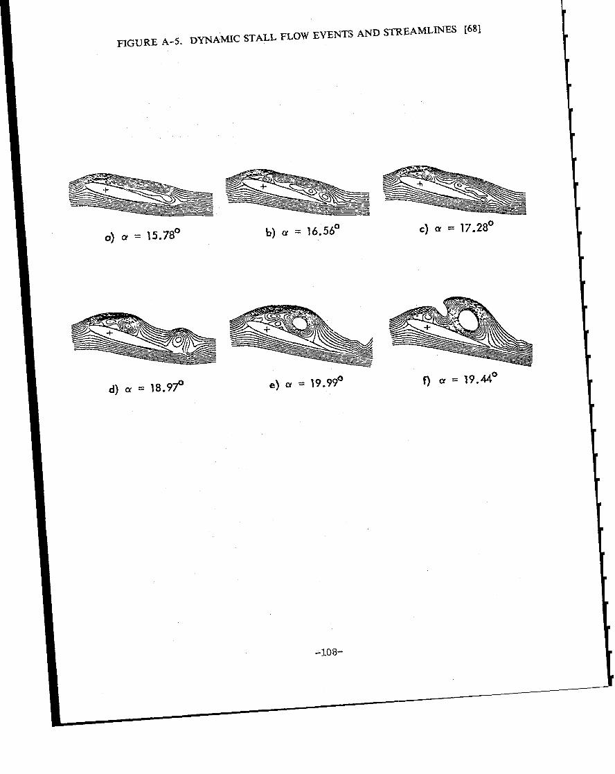
FIGURE A-5. DYNAMIC STALL FLOW EVENTS AND STREAMLINES [68]
(y) (x = 15.78°
d)cx= 18.97
.----- -’.
-=
~~z -~.--=-——.=b) ~ = 16.56°
e) a = 19.99°
-108-
C) a = 17.28°
f)cr = 19.44°

WII’W3TURBINE CON4PAR1SON
The rotor largely determines the performance, reliability, and especially weight ofthe rest of the system. This Section presents two examples in the 15-meter diameterclass, of horizontal axis wind turbines which illustrate this. These turbines representtwo production machines with similar cost and output. They should be viewed as twodemonstrated design approaches to rotor aerodynamic design, even though they have verydifferent deployment, operating, and development histories.
The example contrasts a high tip speed ratio approach with a low tip speed ratioapproach. Both are stall-controlled rotors. The aerodynamic ranges of the airfoils onthese two rotors are very different, as are the weights.
Table 1. Rotor Comparison
Manufacturer Storm Master Bonus—-. .
Diameter 40 ft. 50 ft.Number of blades 3 3Design Speed 133 RPM 50.3 RPMTip Speed 279 ft/sec 132 ft/secSolidity 3.2% 1o%Optimum Tip Speed Ratio 9.5 5.5
KW-design power output 50 @ 35 MPH 55 @ 28 MPHAnnual Productivity 125,000 KW-h/yr 140,000KW-h/yr
Rotor Weight 420 lb. 2645 lb.Aloft Weight 2100 lb. 10748 lb.Tower Weight 2900 lb. 15211 lb.
Blade Mass Moment, I 140 Slug-ftz 2573 slug-ft2Lock number 11.4 5Airfoil NACA 4415 NACA 4415Flap frequency, p 1.05 3.46Max. transient tip deflection 4.5 ft. 0.5 ft.
Thrust @ rated 2000 lb. 2500 lb.Blade loading @ rated 49.7 lb/ft2 12.7 lb/ft2Disc loading @ rated 1.6 lb/ft2 1.3 lb/ft2Gravity cyclic, # cycles/yr 40 X 106 15 X 106
-1o9-

Steaclv Aerodynamics
In the previous discussion the free stream V.. was constant and RPM was variecl tochange ?ngle of attack. The two turbines of this example are constant speed, fixed-pitchdesigns. The angle of attack varies only with wind speed. ‘Thus, the operating pointon the nondimensional coefficient characteristic is determined by the wind speed alone.The CT and CP curves from the strip theory are given for these two rotors in FigureA-6.’
At low wind speed, the tip speed ratio is high, so cut-in wind speed occurs at theX-intercept where CP is just positive. This is very close to the Zero Slip Case, and ascan be seen in the Bonus example, thrust coefficient is already high at this pointowing to the flat blade angle. As wind speed increases, tip speed ratio decreases, angleof attack on the blades increases, and output power and thrust increase. The inducedvelocity is increasing from nearly zero at cut-in, to about 1/3 at maximum CP.
Increasing wind speed further, increases angle of attack and induced velocity untilstall is reached on some part of the blade. Actually the points of maximum CP forboth the Bonus and Storm Master have substantial stall already on the inboard bladesections. With increased free stream Vp and deepening stall, comes Turbulent WakeState, and CP falls off rapidly, CT falling more slowly. Even though CT is falling,dimensional thrust is increasing due to the V-squared effect. As can be seen in thenext curves, dimensional power actually stays about constant for both turbines, droppingoff in a controlled way with increasing wind speed. This is precisely the designphilosophy termed “stall control” for fixed-pitch wind turbines. It means the bladesstall as tip speed ratio decreases, so output power is limited. Thrust, on the otherhand, actually continues to increase for both these turbines.
The power curves are given in Figure A-7. These are just the dimensional plots ofsteady output power vs. steady wind speed. The power curve is the most significantcomparator at present in the wind turbine industry since ideal yearly income is foundby simply integrating this characteristic over the expected site annual wind speeddistribution. The Method of Bins experimental technique is widely used at present in theindustry to obtain the power curve.
As can be seen in the curves, both turbines continue to produce close to ratedpower in extremely high winds, by design. The rotors have actually become “dragdevices” with very low power coefficients.
The point of maximum CP is also seen to occur at about 11/2of the range betweencut-in and rated speed. This is accomplished by deliberate sizing of the drivetrain andgenerator, since some analytical studies have shown optimum productivity for such apower curve characteristic when integrated with an ideal wind speed distribution.Variations in this optimum load matching point are now known to be significantlydependent on the site average wind conditions a high wind site having a largeinstalled power to rotor area ratio, and a low wind site just the reverse.
-11o-

FIGURE A-6. ROTOR COMPARISON: THRUST AND POWER COEFFICIENT
I .0
0.8
0.6
1
CT
BONUS
STORM MASTER
0.4 –
0.2 “
o- 1 I I I 1 I I I I I I I0 2 4 6 8 10 12
TIP SPEED RATIO ~o
0.6 rBONUS
0.4 —
CpSTORM MASTER
0.2 —
o0 2 4 6 0 10 12
TIP SPEED RATlO

FIGURE A-7. ROTOR COMPARISON: POWER CURVES
KW80
70
Cp 600.5 50
I0.4 40
[
0.3 30
0.2 20
0.1 10
00
Cp
0.5
0.4
0.3
0.2
0.1
0 I
- Cp
I“o 10 20 30 40 50 60 70 80
WIND SPEED (MPH)
KW80 —
70 —
60 —
50 —
40 –
30 –
20 –
10 —
0’0 10 20 30 40 50 60 70 80
WIND SPEED (MPH)
-112-

For the two example rotors the following table is given for the 3/4-span airfoilsection at rated conditions. A single inflow gust is superimposed a l/4-second gustfrom 30 to 40 MPH.
Table 2. Airfoil Comparison r/R = 0.75
Storm Master Bonus
Chord 0.667 ft. 2.2 ft.Local speed (Omega X r) 210 ft/sec 99 ft/secAirfoil type NACA 4415 NACA 4415Blade loading 50 lb/ft2 12.7 lb/ft2
or 75 lb/span ft. or 5.8 lb/span ft.
Lift coefficient 1.20 .20Angle of attack 8 deg. -2 deg.
Due to sharp-edged gust (1/4 see gust from 30 to 40 MPH)
Delta angle of attack 4 deg. 8.4 deg.Rate of change of alpha 16 deg/sec 33 deg/secReduced frequency .001 .012
Same gust effect at r/R = 0.25 span station inboard:
Delta angle of attack 12 deg. 25 deg.Rate of change 48 deg/sec 100 deg/secReduced frequency .008 .116
The reduced frequency is a nondimensional measure of the time to convect a perturbationacross the airfoil from leading to trailing edge. A value of 1.0 indicates a pitch excursionevent, [d/dt (alpha) X chord], which has the same period as the local section streamconvection, [(rotor speed) X (span station radius)]. A reduced frequency of 0.1 or greater,coupled with high angle of attack, or high CL, indicates dynamic stall.
As can be seen in Table 2 above, the Bonus wind turbine is susceptible to dynamic stallon the inboard sections for the example axial gust. The high solidity, low-RPM approachreduces the free stream convection to the point where this relatively common gust willcause unsteady lift effects on the inboard portion of blade. The integrated effect of thison blade loading and performance is still open for investigation.
Fixed Pitch vs. Variable Pitch
The above example dealt with relatively small turbines, of the 15-meter diameter class.These were fixed-pitch, stall-controlled, constant RPM turbines, and the aerodynamicvariations and perturbations were caused by variation in the incident wind speed only. It isobvious that the fixed-pitch design, though simpler mechanically, has the great disadvantageof aerodynamic compromise the pitch angle must be chosen for a single rotor flow
-113-

condition, power coefficient, thrust coefficient, and blade angle of attack distribution. Itfollows from the plots of the last Section that the power coefficient is high at really onlyone wind speed. This necessity to compromise performance has led to blade geometric (e.g.,twist and taper) design effort which results in “tip speed ratio-tolerant” rotor designs.Simply stated, such designs have relatively high power coefficients over a wide range of tipspeed ratios, which corresponds to the range expected at the intended site. The Bonuspower curve is an example of this.
Another disadvantage of the fixed pitch approach is vulnerability. The fixed pitch rotormust always present its blades flatwise to high winds, gusts, and precipitation. Lastly, thefixed pitch compromise design point chosen for good performance at rated winds usuallyresults in very poor static torque at low winds; that is, torque coefficient at startup is lowor even negative, as is the case for fixed pitch vertical axis designs. This effect can belargely mitigated by large blade platform (solidity) and twist in the low tip speed ratiodesigns of smaller diameters.
For these reasons very large turbines have usually been pitch-controlled rather thanstall-controlled. Some portion of the blade up to full span has pitching freedom up to thelimit of full feather. The disadvantage of pitching freedom is complexity and associatedcost. However, the pitch-control turbine can always be made to be self-starting and feathered(stable) in extreme conditions. The pitch-controlled machine also can directly alter bladeangle of attack, thereby modulate pitch angle to vary the tolrque and thrust characteristicsto obtain higher performance or lower vulnerability (see Fi{;ure A-8).
The steady aerodynamics of the pitch-controlled turbines are thus very different than forthe fixed-pitch designs. However, the unsteady aerodynamics are much the same. Pitchingmechanisms do not have the capability to “shed loads” because the control pitching rates arenot fast enough. For example, the rotor of the graph (Figure A-8) is a 20-meter design,and the design pitching rate is only 8 degrees/second, which is an order of magnitude lowerthan the unsteady axial gust-induced rate of change in angle of attack. Therefore, the highfrequency turbulence spectrum may cause very similar loading effects on both fixed- andvariable-pitch rotors.
-114-

FIGURE A-3. VARIOUS COEFFICIENTS VS. TIP SPEED RATIO
1.0 r0.8
0.6
0.4
0.2
0 I I I I 1 I I I I I 1 Io 2 4 6 8 10 12
TIP SPEED RATlO
0.08 ~
0.06 –
CQ0.04 –
0.02 “
oI
o 2 4 6 8 10 12
TIP SPEED RATl O &n
Cp
0.6
0.5
0.4 -
0.3 -
0.2 -
00 2 4 6 8 10 12
TIP SPEED RATlO

APPENDIX 3. SUMMARY OF GENERIC DESIGN APPROACHES
This Appendix presents the generic design approaches that were judged by the Panelto be most significant to continuing improvement in wind turbine aerodynamics. Theseapproaches are somewhat indicative of specific hardware configurations, but theremarks are kept as general as possible so as not to be too specific to any certainmechanical design. The approaches, their requirements, characteristics, chief unknowns,known limitations, and possible improvements in performance and reliability, aresummarized in Figure 2.
STALL CONTROL
The approach of stall-controlled rotors specifically means the use of normal airfoilstall, and its normal attenuation of blade lift, to limit load in the control region aboverated wind speed. This approach uses fixed pitch and constant speed (RPM) to achievestalling levels of angle of attack in high winds (see Figure A-7). The aerodynamicrequirements for this approach are that the airfoil have a predictable and repeatablestalling characteristic, with a gentle transition between the rmstalled and stalledoperation. This indicates the need for a trailing edge stalling type airfoil, whichnormally has a thick airfoil section and large leading edge radius (see Figure 4).Additional characteristics are that the rotor operate at low RPM and has large solidity.The thick airfoil sections and large leading edge radius require a large chord, and alow RPM is required to achieve high angles of attack in modlerate winds.
The stall-controlled rotor thus sets up an aerodynamic condition where average liftcoefficient is high at rated power, the load-limiting capability depends on passiveairfoil stall, and large blade areas are exposed to extreme winds. Nevertheless, thistype of rotor has been the most successful to date in the industry, due to the“boilerplate” nature of the rotor.
Currently, the size of stall-controlled rotors is thought to be limited by stall flutter[30], which is the inevitable result of the aerodynamic condition described above beingcombined with a blade stiffness high enough to cause large flapping velocities (seeFigures A-9 and A-10). The historical solution is structural, and involves eithermaking the blade stiffer (push the flutter boundary higher), or considerably less stiflf(articulate or teeter the rotor). A more recently-proposed solution [32] is aerodynamicin which the airfoil is changed to have unique stalling characteristic not common tohistorical airfoils: the lift in this case does not fall after stall is reached, but stayspractically constant, at the level of CL-max. This change removes the drop in CL-maxthat provides a steady-state limit cycle hysteresis, which is the stall flutter mechanism.
-116-
The chief unknowns in current design methodology for stall control are theprediction of unsteady airloads, prediction of the stalled behavior attainment of arepeatable transition through the stalling point, and assessment of the effect ofroughness.

FIGURE A-9. NIBE A AND B WIND TURBINES [30]
B
L-NIBE
—
/.
d
u
D
NIBE B
I
4
e
+“ .—. — . .—. — .—. — .
*NIBE A
II
-k,/ sm~lzm ------J
FIBER GLASS SPARSTEEL SPAR ‘ I
.
+● �✎� ✎�✎ � ✎�✎ � ✎
✼
NIBE B
-117-

,..0 ,.,, ~. i ~ ~ : ‘,-,.:--: :,.
,.——. —. ;.-...-------....- .-.:. ...----; ‘ @&@AWkk2;2z?x.
..... .. ..- +*.J_.+ ... :____ .:[
...----- ...... . . . .. . ...-.... . ----:-4 .. .....------------1.
...... .. . .. ... .. .... .. . .. .. . . ... .... . . . .... ....... .. .. ..... -, , ..- ._ :._ ... . 1-.-- :._. . . . . . . -.
,.. !Vr, ;!; :, I .:
-~.:. .;:: :. :.. :.-—. - —.-.—- ... .....— -----
.——. . :. .:.-—. -. --;;:
——.---—— -. -... —.. .- ... .--- .—.—.----- .- f?’f’fW+e%’; ;--”-y--j: ~-— — ::-. . . ..;.......------............ .---- ......—-.-——.-------—- ——.-—----.-....—-.-+_#2iEii.
. . .. ... ... ..... . ... . . ...~. ...,.i.: . .. ...;.,... .. ......
.. . . .. ... . . 1 . . . . . . . .
a ●
.+
‘ ‘.-L-i.-: ‘ 44iMe!k!!k!.ie-._--L_. ._E-—.-u .-—
.. ....+.. ... ......... ..- .+-..:. .. ... . . . ...
.i...L-...L.-L...Li-&_i--_ .-i
FIGURE
Nibe
. . ~ . . ..-. . ... ..==,&~._2: ;.. ~ J......i... ~...:.-—.-—— —- —
A Wind Turbine Chordwiseand Flapwise Blade BendingMoments During Normal Operationand Stall-Induced Vibrations
A-10. NIBE A TURBINE STALL-INDU[;ED VIBRATIONS [30]
-118-

With proper effort expended on the unsteady aerodynamics and inflow as outlined inthis Technical Assessment, about a 25V0improvement in energy capture and significantfurther improvement in fatigue life are possible. This will be possible with a newunsteady aerodynamics technology base which will yield improved knowledge of theunsteady airloads and their fatigue effect, and provide the ability to reduce the weight,cost, and structure needed with improved unsteady airfoils.
PITCH CONTROL
Pitch-controlled rotors simply employ pitch angle changes to control loading. Apitch-controlled rotor can be used with constant speed or variable speed. The pitchdegree of freedom requires a control system and algorithm (strategy), with manyoptions for varying angle of attack in various control regions to improve performance.There is no compelling aerodynamic requirement that the airfoil stall gently, so a widerrange of airfoils with higher performance and thinner sections can be used. Theoperating RPM as well is not constrained in order to produce high angles of attack, sothe pitch-control machine can have a much higher operating tip speed and lowersolidity.
The use of pitch-control allows another degree of freedom with which to extend theenvelope of performance, and is thus not restricted to the load limit region. Pitchcontrol can be used at any time when the average lift coefficient must be reduced. Anexample is the overspeed or shutdown control function (see Figure 17). The pitchingdegree of freedom is similar to the variable speed degree of freedom in that constant(average) angle of attack can be maintained on the blade (see Figure 26). Thedifference is in the unsteady behavior, which is driven by control limits in the formerand rotor inertia in the latter.
The pitch-control machine is vulnerable to large transient airloads during pitchmotions if the pitch rate is too high (see Figure A-11 [69]). In the load controlregion, the pitch control approach may result in higher transient gust loading sincedynamic stalt may force very high momentary lift coefficients, at a rate too high forpitch following.
Possible improvements to the pitch-controlled rotor are the same as for the stall-controlled rotor. It is not likely that either one will be able to avoid dynamic stallentirely.
VARIABLE SPEED
The variable speedoperate at constant tip
wind turbine can be either fixed or variable pitch, but mustspeed ratio in the rising power region (control region 2). The
requirement is that the driven load match the output torque ~ the square of RPM, andthus restrains the rotor to operate at constant tip speed ratio, where the RPM islinear with wind speed. Other variable speed options are possible, but the performancebenefits are clearest with constant tip speed ratio operation. The turbine operates atits single best design point, or rotor efficiency, so the power coefficient is maximized(see Figure A-3). ‘Load co”ntrol isthis is achievable in various ways,
still necessary in the- region above ratedsuch as pitch change and forced yaw.
-119-
power, and

FIGURE A-11 . NIBE B TURBINE: HIGH AERODYNAMIC BRAKING LOAD [69]
.-— — . .I . @ltt* ~~~ ,.- %, . . -----. . .----. . .. ... . .. ..-— . . . ..-..----
93q4+& . . .’. -””.””-=::__z:” ::Hl-”:- ~-==’-’’+’:- ‘- ~-”. . . -
. . .. —-----..-.— ----- -–-..-—.-.-_-+. ------——:.::.”_— - ---- .. .. ...
J ::---- =.--.=---”--”- -:._. .. .----- ----- ...._..:_ .--+: . ._”. .:,:.L-- -
i.-- ——.—----- - .-,-— --—. .—.--...,___ .—- .—--—-. —..-. —. --— . .-— ....- -... -—----- ---- .-
Eepney &k. /&.
&L++-.+ --i ---- - -. .
. ..- -.-: --..— .-—.
[
~~~-
- __LA&b@e:... --—---—-. --.—_A._ :-L n5kzw6r_ -——-A.- . ..-. . ---- .- ----.: —- .— -- .“— .--— . - .-.4----- —.— ----
. . .—. .-. -!. - .- .-. .
.-.
--=-— .— -— —-. .-. —. - -— .--, .. --— —
. ----- -----
( &d&u4d!.28@+Ltin.x: ;.T;7’”++-,__ ,.9R.SNu+- ,,+94 i:. -m UC-* I,4UJZ14-. !“*.-’=”- s>..-O...* - 1.4 .W8..0-r S,*-,e,.-
- /.:.zL-:IAmx2 ----- ——. -.-. ..— .. . — .—------ .------ .. &.-. . ------ -----
--i ‘“””.—------4--... —— . - -. - -
-.—-——— . —---.
1
.— ----- .- -----
—-. — —- ..: ---- -—. . . -
/* . . . . .—. - ------- . .
+# ———- —.- —- .- . .
I“ i“.~-+-2?v2!??!l- -{ZI:”E+i:i~;”z~z<–=; :--:.-1:::-.:””,:——.-.”-. — . . . . . .
-
~ -..=-: -:” .-”-. :_____ - -.--. —..-- —-——— -z ——- —- - --- . . . . . . . . . .-
-. -.-— ——. . . . . . . . . . . . . . . . . . . . . . . . . . .
-- —— --- .-—. - . . . . . .- .
+ . .. ---- —.. Lo “- - ‘“ ‘--: ‘--: -~i---------~~”~--’”
I @p@J.*g-=- Am - ‘“------ . ...- --
i“””-.- -........ --- --------.-.- .4
I e -— — ._::::!F-T’‘:’””’Nibe B Wind Turbine Root BendingMoments, Showing High BrakingTransient Loads Due To HighPitching Rate of Blade Feathering
-120-

One of the characteristics of constant tip speed ratio operation is that the rotoroperates in load equilibrium, with the aerodynamic and inertial (centrifugal) loads inbalance, and the average coning angle constant (see Chapter 7). This similaritycondition holds for large rotors also, but the gravity loads do not scale, and thisprobably limits the large sizes [57]. Variable speed operation maintains constant(average) angle of attack on the rotor, and is comparable to pitch control in this way.Fluctuations about this equilibrium point are determined by the unsteady inflow and therotor inertia.
Limitations of this approach consist mainly of the necessary driven load control.The only type of load which achieves this square-law torque matching exactly is a fluidmechanics device (as the rotor is also) such as a mechanical water pump or churn [70].
The possible improvements for a variable speed rotor, given the technology advancesput forth in this Assessment, are similar to the stall- and pitch-control options.
DARRIEIJS (VAWT)
The Darrieus is a specific design example in the category of vertical axis windturbines. The blades are fixed pitch, rotate about a vertical axis at constant RPM, andhave an approximately troposkein curved shape (see Figure A-12). Compared to HAWTof the same dimensions, the Darrieus has more blade area and weight but due to itslarger “orbit” the rotor may influence a larger free streamtube. For this reason, it isnot clear that the VAWT is restricted to the traditional Betz limit based on swept areafor actuator performance, which is true for HAWT rotors without flow augmenters.
The Darrieus is independent of inflow direction changes, is a stall-control rotor,and operates at constant pitch, hence requires a separate shutdown system. TheDarrieus airfoil can be said to never operate at steady conditions; the rotor is alwaysin unsteady flow, and is vulnerable to all the unsteady effects possible throughout itslife. This is both an advantage and a disadvantage, since the unsteady effects may beboth.
Possible improvements in energy capture over present designs are estimated toamount to 50°h given a well-performing unsteady airfoil. Possible improvements toairload calculation and fatigue life are at least as high as for HAWT rotors, andprobably higher.
STRAIGHT BLADE VAWT
The straight bladed VAWT (Figure A-13) is another vertical axis approach whichadds a possible degree of freedom in blade pitch as well as speed, blade geometry, andairfoil and traces a larger orbit than equivalent dimension HAWTS. It is also true forthis approach that the Betz limit based on swept area may not apply, since theaffected wind streamtube is unknown. It also operates exclusively in unsteady flowand is subject to both the advantages and disadvantages of dynamic stall.
The pitching freedom allows control options in the various regions to exploitdynamic stall. It may be possible to employ advantageous unsteady airfoils, withappropriate devices to tailor dynamic stall, and force them via the pitching system at
-121-
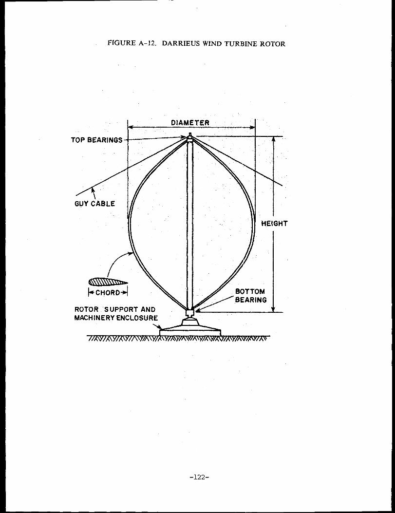
FIGURE A- 12. DARRIEUS WIND TURBINE ROTOR
TOP BEARINGS
4“”GUY C“A8LE
MACHINERYENCLOSURE
—
\
\
‘%
\
—
\\
HEIGHT
/
/
6CNTOM
EAR’”’
‘t-=-l
-122-

A-13. STRAIGHT BLADE
P,
.
AXIS WIND TURBINE
PITCH CHANGE MECHANISM
“’& ~.
-
.,-123-

advantageous frequencies at various points on their orbits to convert their unsteadylift increases into torque without incurring a drag penalty. It is not hard to conceiveof such a VA WT having much higher torque output than present values.
Advances in unsteady load prediction, as for the others,, will also result in adramatic improvement in rotor useful life.
HIGH TIP SPEED RATIO
The high tip speed ratio approach will ljkely be useful for rotors with very lowsolidity and large capture areas that will be used in low to :moderate wind resourceareas where the rotor capture are must be larger for a given installed power output.This approach will become more and more attractive as advances in understandingunsteady airloads and high strength-to-weight structures alllow longer blades and lowerrotor weights.
The high tip speed requires the characteristics of low solidity rotors thin airfoilsfor low profile drag (which determines the upper tip speed limit for all rotors) andoperation at low lift coefficients. The lower lift coefficient and higher speed allowsairfoils to be used which have higher lift/drag ratios and (probably) better (sincehigher) Reynolds number performance. The tip speeds might be high enough thatsupercritical airfoils would be advantageous to delay drag rise at high subsonic Machnumbers. The limitation will be on acceptable noise levels (see Figure 28-30).
Another benefit of high tip speed ratio rotors is the smaller angle of attack cha:ngecaused by inflow turbulence (see Figure 18). The high tip speed ratio turbine is lesssensitive to unsteady aerodynamics effects for two reasons
1. The rotor operates at lower angles of attack.2. Inflow fluctuations induce smaller variation in angle of attack.
An increased burden is placed on aeroelastic analysis and the control functions due tothe more stringent loads and dynamics requirements. Also, the thin airfoils likely tobe used will probably be significantly more sensitive to roughness effects.
Possible improvements over present designs are dramatic. If this approach ispossible, say, with advanced structures, energy capture could be increased by a factorof 2 to 3, which simply represents the larger rotor area which would be possible forthe same cost or weight. Improvements in fatigue life are not as clear, since there isno technology base for comparison.
FREE YAW (HAWT)
The free yaw approach has the benefit of no active yaw sensors, actuators, ormaintenance. The rotor for a free yaw turbine would by itself be stable in theunsteady inflow field, and have no average steady yaw tracking error. Present fieldexperience indicates that active yaw systems are now, and will continue to be, highmaintenance items [71], and that steady yaw tracking errors exist primarily due to theuncertainty of proper unsteady inflow measurement with the external sensors necessary[26].
-124-

The chief unknown in this approach is a detailed parametric knowledge of ‘theaerodynamic yaw stability derivative, which is the restoring yawing moment. It islikely that dynamic stall plays a major role in determining this derivative for any setof unsteady conditions, just as for the unsteady airloads.
The possible improvement will be an increase in captured energy and a decrease incyclic loadin~ both will result from better directional stability in unsteady flow.
-125-
APPENDIX 4. WIND TURBINE INDUSTRY REPRESENTATIVESAND SITES VISITED, JULY 1985
Wind Turbine Industry Briefing, Oakland, California, July 10-12, 1985:
Craig Hansen, University of Utah
Clint Coleman, North Wind Power Company
Jay Carter, Jr., Carter Wind Systems
Glidden Doman, Hamilton Standard
Herman Drees, FloWind Corporation
Jamie Chapman, U.S. Windpower, Inc.
Vaughn Nelson, West Texas State Univ.
Mike Zuteck, Consultant, Gougeon Bros.
M. C. Cheney, Windtech, Inc.
Wind Turbine Site Visits, California, July 12, 1985:
Boeing/PGE Mod-II Wind Turbine, Fairfield
U.S. Windpower, Altamont Pass
Altamont Energy Corp., Altamont Pass
Fayette Manufacturing Corp., Altamont
Howden Wind Parks, Altamont Pass
Pass
-126- .IJ S GOVERNMENT PRINTING OFFICE 1986-491-177 50002