wind turbine design
TRANSCRIPT

Wind Turbine
Design
Win
d T
urb
ine
Des
ign
W
ith E
mp
hasi
s on
Dar
rieu
s C
once
pt
Ion
Par
asch
ivoiu
Wind Turbine Design
www.polymtl.ca/pub
ISBN : 978-2-553-00931-0
9 782553 009310
With Emphasis on Darrieus Concept
With
Em
pha
sis
on D
arri
eus
Con
cep
t
The depletion of global fossil fuel reserves combined with mount-
ing environmental concerns has served to focus attention on the development of
ecologically compatible and renewable «alterna-tive» sources of energy.
Wind energy, with its impressive growth rate of 50% over the last five years, is the fastest growing alternate source
of energy in the world since its purely economic potential is complemented by its great positive environmental impact. The
wind turbine, whether it may be a Horizontal-Axis Wind Turbine (HAWT) or a Vertical-Axis Wind Turbine (VAWT), offers a practical
way to convert the wind energy into electrical or mechanical energy. Although this book focuses on the aerodynamic design and performance
of VAWTs based on the Darrieus concept, it also discusses the compari-son between HAWTs and VAWTs, future trends in design and the inherent
socio-economic and environmental friendly aspects of wind energy as an alternate source of energy.
This book will be of great interest to students in Mechanical and Aero nautical Engineering field, professional engineers, university professors and researchers in
universities, government and industry. It will also be of interest to all researchers involved in theoretical, computational and experimental methods used in wind tur-
bine design and wind energy development.
Dr. Ion Paraschivoiu is J.-A. Bombardier Aeronautical Chair Professor at École Polytechnique de Montréal where he is teaching undergraduate and graduate
courses in Aerodynamics. He has made significant contributions to the theory of the aerodynamic performance of the Darrieus vertical axis wind turbine. His software
programs for these calculations, described in the book, have been used successfully by others for design purposes and to assist in the evaluation of VAWT field tests. His other research interests include application of advanced aerodynamics methods in the study
of aircraft icing, drag prediction and laminar-flow control.
IonParaschivoiu
Excerpt of the full publication
Extrait distribué par Presses Internationales Polytechnique

dedicace.p65 12/11/2009, 09:154

Wind Turbine
DesignW
ith
Em
ph
asis
on
Dar
rieu
s C
on
cep
t
ION
PARASCHIVOIU
Presses internationales
P o l y t e c h n i q u e
Page_titre.p65 12/11/2009, 09:161
Excerpt of the full publication

Wind Turbine Design – With Emphasis on Darrieus ConceptIon Paraschivoiu
Production teamEditorial management and production: Presses internationales PolytechniqueEditing: Stephen SchettiniIllustrations: Farooq SaeedCover Page: Cyclone Design
For information on distribution and points of sale, see our Website: www.polymtl.ca/pubE-mail of Presses internationales Polytechnique: [email protected] of Ion Paraschivoiu: [email protected]
We acknowledge the financial support of the Government of Canada through the Book Pu-blishing Industry Development Program (BPIDP) for our publishing activities.
Government of Québec — Tax credit for book publishing — Administered by SODEC
All rights reserved.© Presses internationales Polytechnique, 2002
Reprinted December 2009.
This book may not be duplicated in any way without the express written consent of the publisher.
Legal deposit: 4th quarter 2002 ISBN 978-2-553-00931-0 (printed version)Bibliothèque et Archives nationales du Québec ISBN 978-2-553-01594-6 (pdf version)Library and Archives Canada Printed in Canada
Excerpt of the full publication

To my daughter Gloriaand my wife Liliana
“When the wind is blowingThe wind turbine is turning
The electricity is flowingThe gas emissions are ceasing
The environment is refreshingAnd people are cheering”
I.P.
dedicace.p65 12/11/2009, 09:153

dedicace.p65 12/11/2009, 09:154

Foreword v
This book is intended to be a good reference for anyone interested in the design ofVertical-Axis Wind Turbine for electricity generation and other applications such as pumpingwater, irrigation, grinding and drying grain, and heating water to name a few.
The book is divided into ten chapters that are presented in a logical manner. The content iseasy to follow and each chapter has its own conclusions. The innovative nature of this book isin its comprehensive review of state of the art in Vertical-Axis Wind Turbine (VAWT),correlation of existing knowledge base and the more recent developments in understanding thephysics of flow associated with the Darrieus type vertical-axis wind turbine. The principaltheories and aerodynamic models for performance calculations are presented with experimentaldata, not only from laboratory measurements but also from real prototypes.
The first chapter presents an introductory topic on the wind characteristics, a brief descrip-tion of the components of both major categories of wind machines: Horizontal-Axis WindTurbine (HAWT) and Vertical-Axis Wind Turbine (VAWT) and an overview of the wind energydevelopment in the world.
The state of the art of vertical-axis wind turbine including Savonius and Giromill rotors aredescribed in Chapter 2.
The scope of Chapter 3 encompasses the mathematical formulation of the equations for thevarious Darrieus rotor configurations as well as geometries including: catenary, parabolic,troposkien and modified troposkien blade and also a practical Sandia type shape.
The aerodynamic performance prediction models are presented in Chapter 4 for: singlestreamtube, multiple streamtube, vortex and local-circulation models. The aerodynamic loads:normal and tangential components and performance, as well as, rotor torque and power coeffi-cient are calculated and the comparisons of different prediction models are shown.
The unsteady aerodynamics of Darrieus type VAWTs is dealt with in detail in Chapter 5. ACFD model based on the streamfunction-vorticity formulation of the Navier-Stokes equations ispresented to study and highlight unsteady effects that may influence design and performance.
The real essence of the book is in Chapter 6 that provides a practical design model for theDarrieus type VAWTs based on the double-multiple streamtube model, originally developed bythe author. Several variants of the software program CARDAAV, for use in performancecalculations, are described. Other important aspects such as rotor geometries, conventional andnatural laminar flow airfoils, dynamic-stall effects, secondary effects and stochastic wind modelare also addressed here.
The subsequent chapters present aerodynamic load and performance data from waterchannel and wind tunnel experiments, the state of the art of innovative aerodynamic devices asapplied to VAWTs and the future trends in the design of Darrieus type wind turbine.
Foreword.p65 19/11/2009, 09:485
Excerpt of the full publication

vi Foreword
A comparison between Horizontal-Axis and Vertical-Axis Wind Turbines is given in Chapter 9.The idea here is to keep in perspective the technical aspects and the global cost of the advanceddesigns for both kinds of machines.
Finally, Chapter 10 deals with the environmental and social aspects of wind energy since itis an emerging environmental technology of great impact and value.
The author is indebted to Research Institute of Hydro-Quebec (IREQ) and to his manygraduate students and researchers: Drs. T. Brahimi, A. Allet, R. Martinuzzi, K. F. Tchon,C. Masson, S. Hallé and L. Surugiu formerly of the J.-A. Bombardier Aeronautical Chair,Department of Mechanical Engineering at École Polytechnique of Montreal, for their help inpreparing this book. The author would like to extend his gratitude to the Department ofMechanical Engineering at École Polytechnique of Montreal, CANMET in Ottawa and NorbertVoutthi Dy, Ph.D. candidate (2009 edition) for all their assistance in preparing this book.
This book has been gracefully translated in Japanese with the help of a team: ProfessorEmeritus Tsutomu Hayashi (leader), and Dr. Yutaka Hara from Tottori University, and ProfessorTetuya Kawamura from Ochanomizu University, Tokyo.
Special contributions in the preparation of this reference book were made by Mr. Jack R.Templin, formerly with the National Research Council of Canada, Dr. Claude Béguier, formerlywith Institute of Research on Phenomena out of Equilibrium (IRPHE) − Marseilles, France, Prof.Raghu S. Raghunathan of Queen’s University of Belfast, Dr. Takao Maeda and Prof. YukimaruShimizu, Mie University, Japan, who provided useful comments and constructive suggestions asreviewers of the manuscript.
The author gratefully acknowledges the advice and valuable remarks of his many friendsfrom Sandia National Laboratories during several meetings and conferences that spanned fortwo decades, as well as Drs. Paul C. Klimas, Jim H. Strickland, Dale E. Berg, Paul G. Migliore,Paul S. Veers, Herbert Sutherland, Williams N. Sullivan, Donald W. Lobitz, Tom Ashwill, etc.
The author would especially like to thank Dr. David Malcolm, Global Energy Concepts,LLC, and Dr. Lawrence Schienbein for providing important experimental data and extensiveinformation on Darrieus wind turbine, Carl Brothers from Atlantic Wind Test Site at PrinceEdward Island (Canada) for helpful discussion on the comparison between horizontal-axis andvertical-axis wind turbines, Prof. Kazuichi Seki of Tokai University, Japan, Prof. GeraldGregorek, Ohio State University, Columbus, USA, for his interesting discussions, Dr. GaneshRajagopalan, Iowa State University, Ames, USA, and Dr. A. Jagadeesh of Nayudamma Centerfor Development of Alternatives, Andhra Pradesh, India, for his discussions specifically on theenvironmental aspects of wind energy. The author would like to acknowledge and thank, ingeneral, the wind energy fraternity and, in particular, to Prof. Holt Ashley, Dr. Al Eggers,Prof. Robert E. Wilson, Mr. Raj Rangi and Dr. Robert Thresher.
The author would like to express his acknowledgments and special thanks to Dr. FarooqSaeed, formerly research associate of J.-A. Bombardier Aeronautical Chair, for his valuableassistance in the preparation of this manuscript. Last but not the least, the author would like tothank Mrs. Diane Ratel and Mrs. Martine Aubry for their skillful editing and typing of thebook and also to Mr. Lucien Foisy and Mrs. Constance Forest (2009 edition) for their help in itspublication by Presses internationales Polytechnique.
Ion Paraschivoiu
Foreword.p65 19/11/2009, 09:486
Extrait distribué par Presses Internationales Polytechnique

Table of Contents vii
Foreword ........................................................................................................................................ vList of Figures ............................................................................................................................. xiiiList of Tables ............................................................................................................................. xxiii
1.1 Wind Definition and Characteristics ................................................................................... 11.2 Wind Turbines ...................................................................................................................... 11.3 Wind Energy Applications ................................................................................................... 51.4 Benefits and Obstacles in Wind Energy Development ....................................................... 61.5 Overview of Wind Energy Development ............................................................................ 81.6 Wind Energy Development in the World ............................................................................ 81.7 Cost of Wind Energy .......................................................................................................... 101.8 Social Cost of Wind Energy .............................................................................................. 11Conclusions .................................................................................................................................. 13References .................................................................................................................................... 13
2.1 The Madaras Rotor Concept .............................................................................................. 152.2 Savonius Rotor ................................................................................................................... 16
2.2.1 Mathematical Model ............................................................................................. 172.2.2 Experimental Study ............................................................................................... 20
2.3 Drag-Driven Device ........................................................................................................... 252.4 Lift-Driven Device ............................................................................................................. 262.5 Giromill .............................................................................................................................. 282.6 Vortex Modeling Cross-Wind Axis Machine .................................................................... 322.7 Aerodynamic Characteristics ............................................................................................. 34References .................................................................................................................................... 34
3.1 Introduction ........................................................................................................................ 373.2 Geometry of the Darrieus Rotor ........................................................................................ 41References .................................................................................................................................... 61
! "#"#$
4.1 Single Streamtube Model ................................................................................................... 664.1.1 Aerodynamic Performance ................................................................................... 70
Table_Contents.p65 19/11/2009, 13:507
Extrait distribué par Presses Internationales Polytechnique

viii Table of Contents
4.1.2 Comparison of Single Streamtube Model with Experiment ................................ 71Conclusions ........................................................................................................................ 76
4.2 Multiple Streamtubes Model ............................................................................................. 774.3 Vortex Models .................................................................................................................... 85
4.3.1 Free-Wake Vortex Model ...................................................................................... 864.3.2 Fixed-Wake Vortex Model .................................................................................... 874.3.3 Comparisons between Vortex Models and Experiment ....................................... 88
4.4 A High-Speed Lifting Line Model .................................................................................... 904.4.1 Results and Discussion ......................................................................................... 94
4.5 Local-Circulation Model .................................................................................................... 97References .................................................................................................................................... 98
% &"−−−−−' $5.1 Introduction ...................................................................................................................... 101
5.1.1 Dynamic-Stall Phenomenon ............................................................................... 1045.1.2 Numerical Simulation of Dynamic Stall ............................................................ 105
5.2 Numerical Procedure ........................................................................................................ 1065.2.1 Governing Equations .......................................................................................... 1065.2.2 Boundary Conditions .......................................................................................... 1085.2.3 Finite Element Discretization ............................................................................. 1095.2.4 Element Influence Matrices ................................................................................ 1105.2.5 Newton Linearization .......................................................................................... 1125.2.6 Algorithm ............................................................................................................ 113
5.3 Turbulence Modeling ....................................................................................................... 1145.3.1 Cebeci-Smith Model ........................................................................................... 1145.3.2 Johnson-King Model ........................................................................................... 118
5.4 Results and Discussion ..................................................................................................... 1205.4.1 Test Cases ............................................................................................................ 1205.4.2 Darrieus Motion Airfoil ...................................................................................... 1275.4.3 Flow Structure ..................................................................................................... 1305.4.4 Aerodynamic Characteristics .............................................................................. 1365.4.5 Discussion ........................................................................................................... 139
5.5 Conclusions and Recommendations ................................................................................ 141References .................................................................................................................................. 141Appendix to Chapter 5 ............................................................................................................... 144A-5.1 Transformation of the Momentum Equation .............................................................. 144A-5.2 Pressure Uniqueness Condition .................................................................................. 145A-5.3 Computation of the Aerodynamic Coefficients .......................................................... 146
( $ "−−−−−# $6.1 Double Actuator Disk Theory ......................................................................................... 1476.2 Double Actuator Disk Momentum Theory ..................................................................... 1486.3 Blade Element Theory ...................................................................................................... 1536.4 Double-Multiple Streamtube Model for Studying Darrieus Turbine ............................. 156
Table_Contents.p65 19/11/2009, 13:508

Table of Contents ix
6.4.1 Aerodynamic Model ........................................................................................... 1586.4.2 Influence of Secondary Effects on the Aerodynamics of the Darrieus Rotor .. 177Conclusion ........................................................................................................................ 1886.4.3 Streamtube Expansion Model ............................................................................. 189Conclusion ........................................................................................................................ 198
6.5 Aerodynamic Analysis of the Darrieus Wind Turbines Including Dynamic-StallEffects ............................................................................................................................... 1996.5.1 Introduction ......................................................................................................... 2006.5.2 Dynamic-Stall Models ........................................................................................ 201
6.6 Darrieus Rotor Aerodynamics in Turbulent Wind .......................................................... 2266.6.1 Aerodynamic Analysis ........................................................................................ 2286.6.2 Wind Model ......................................................................................................... 230Conclusion ........................................................................................................................ 236
6.7 Comparison with Other Computer Code Predictions ..................................................... 2376.7.1 Aerodynamic Performance ................................................................................. 2376.7.2 Structural Dynamics in Connection with Momentum Models .......................... 238Conclusion ........................................................................................................................ 240
6.8 Blade Tip and Finite Aspect Ratio Effects on the Darrieus Rotor ................................. 2416.9 Performance Predictions of VAWTs with SNL Airfoil Blades ...................................... 247
6.9.1 Performance of Conventional and SNL Blades ................................................. 251Conclusion ........................................................................................................................ 253
6.10 CARDAAV Software ....................................................................................................... 2536.10.1 Rotor Geometry ................................................................................................ 2556.10.2 Operational Conditions ..................................................................................... 2566.10.3 Control Parameters ........................................................................................... 2566.10.4 Results ............................................................................................................... 257Conclusion ........................................................................................................................ 259
References .................................................................................................................................. 259
) "*#"
7.1 Water Channel Experiments ............................................................................................. 2667.1.1 Texas Tech University Tests ............................................................................... 2667.1.2 Water Channel Experiments of Dynamic Stall on Darrieus Rotor ................... 277
7.2 Wind Tunnel Experiments ............................................................................................... 2887.2.1 National Research Council of Canada Wind Tunnel Tests ................................ 2887.2.2 Sandia Research Turbines ................................................................................... 2917.2.3 Predicted and Experimental Aerodynamic Forces on the Darrieus Rotor ........ 296
7.3 Field Test of Darrieus Wind Turbines ............................................................................. 3037.3.1 Sandia 5 Meter Research Turbine ...................................................................... 3037.3.2 NRC/Hydro-Quebec Magdalen Islands 24 Meter Research Turbine ................ 3047.3.3 NRC/DAF 6.1 Meter Research Turbine ............................................................. 3057.3.4 Lavalin Eole (64-m) Research Turbine, (Cap-Chat, Québec) ........................... 3067.3.5 Pionier I (15 Meter) Cantilevered Rotor Research Turbine (Netherlands) ...... 3087.3.6 Sandia 17 Meter Research Turbine .................................................................... 308
Table_Contents.p65 19/11/2009, 13:509
Excerpt of the full publication

x Table of Contents
7.4 Commercial Prototype Wind Turbines ............................................................................ 3127.4.1 DOE 100 kW (17-m) Darrieus Wind Turbine ................................................... 3127.4.2 FloWind 17-m and 19-m Commercial Turbines ................................................ 3127.4.3 Indal Technologies 50 kW (11.2-m) and 6400/500 kW (24-m) ........................ 314
7.5 Measurements and Prediction of Aerodynamic Torques for a DarrieusWind Turbine .................................................................................................................... 3157.5.1 Introduction ......................................................................................................... 3157.5.2 Measurements and Data Reduction .................................................................... 3177.5.3 Prediction of Aerodynamic Torque .................................................................... 3217.5.4 Measured and Predicted Aerodynamic Torque .................................................. 322
References .................................................................................................................................. 326
+ ,--" - .
8.1 Natural Laminar Flow (NLF) Airfoils and Tapered Blades ........................................... 3298.2 Aerobrakes ........................................................................................................................ 340
8.2.1 Spoilers ................................................................................................................ 3418.3 Vortex Generators ............................................................................................................. 3428.4 Pumped Spoiling .............................................................................................................. 3458.5 Toe-In-Angle Effects ........................................................................................................ 3468.6 Blade Camber ................................................................................................................... 3498.7 Blade Roughness (Soiling), Blade Icing and Parasite Drag Effects .............................. 351References .................................................................................................................................. 355
/ '
9.1 Wind Turbine Design Parameters .................................................................................... 3599.1.1 Swept Area .......................................................................................................... 3599.1.2 Rotor Aspect Ratio .............................................................................................. 3629.1.3 Blade Airfoil ........................................................................................................ 3649.1.4 Rotor Speed ......................................................................................................... 3659.1.5 Rotor Solidity ...................................................................................................... 3659.1.6 Blade Material and Construction ........................................................................ 3669.1.7 Central Column of Darrieus Rotor ..................................................................... 3679.1.8 Horizontal Struts ................................................................................................. 3689.1.9 Guy Cables .......................................................................................................... 3689.1.10 Cantilever Darrieus Rotor ................................................................................... 3709.1.11 Type and Location of Brakes .............................................................................. 3709.1.12 Gearbox ............................................................................................................... 3719.1.13 Drive Train .......................................................................................................... 3729.1.14 Motor/Generator .................................................................................................. 3739.1.15 Variable Speed ..................................................................................................... 374
9.2 Darrieus Wind Turbine Design ........................................................................................ 3749.2.1 Darrieus Design Issues ........................................................................................ 3749.2.2 Future Design Alternatives ................................................................................. 375
9.3 Comparison Between Horizontal-Axis and Vertical-Axis Wind Turbines .................... 377
Table_Contents.p65 19/11/2009, 13:5010

Table of Contents xi
9.3.1 HAWTs vs VAWTs Technical Aspects ............................................................... 3779.3.2 Taking VAWTs to Viability ................................................................................. 381
References .................................................................................................................................. 382
0 -"
10.1 Introduction ...................................................................................................................... 38710.2 Environmental Aspects .................................................................................................... 388
10.2.1 Human Environment Aspects ............................................................................. 38910.2.2 Natural Environment Aspects ............................................................................. 39110.2.3 Environmental Effects of Wind Turbine Operation ........................................... 393
10.3 Gas Emissions: Wind and Other Energy Sources ........................................................... 39410.4 Public Attitudes in Various Countries ............................................................................. 39610.5 Social Impact .................................................................................................................... 39810.6 Wind Power and Traditional Power Sources .................................................................. 398Conclusions ................................................................................................................................ 401References .................................................................................................................................. 401
Appendix A Aerodynamic Characteristics of Symmetrical Airfoils ................................... 405
Appendix B Canada and Worldwide Wind Energy Production ........................................... 417
Appendix C Wind Energy on the Worldwide Web .............................................................. 425
Index .......................................................................................................................................... 427
Table_Contents.p65 19/11/2009, 13:5011

xii Table of Contents
Table_Contents.p65 19/11/2009, 13:5012

List of Figures xiii
Figure 1.1 Components - Upwind rotor and downwind HAWT rotor [Ref. 1.1] ........................ 2Figure 1.2 VAWT of Darrieus type [Ref. 1.1] .............................................................................. 3Figure 1.3 Types of vertical-axis wind turbines - a) Fixed bladed Darrieus or
articulating blade Giromill; b) Savonius rotor ............................................................ 4
Figure 2.1 The Madaras concept for generating electricity using the Magnuseffect [2.1] .................................................................................................................. 15
Figure 2.2 Savonius rotor - Calculation scheme ........................................................................ 17Figure 2.3 Pressure distribution vs azimuthal angle ................................................................... 18Figure 2.4 Starting torque for a rotation ..................................................................................... 19Figure 2.5 Normalized power coefficient vs bucket tip-speed ratio .......................................... 20Figure 2.6 Two-bucket Savonius rotor ........................................................................................ 21Figure 2.7 Three-bucket Savonius rotor ...................................................................................... 21Figure 2.8 The static torque coefficient as a function of angular position for a
two-bucket Savonius rotor, [2.17] ............................................................................. 23Figure 2.9 The static torque coefficient as a function of angular position for a
three-bucket Savonius rotor, [2.17] ........................................................................... 23Figure 2.10 A comparison of the power coefficients for two- and three-bucket Savonius
rotors with a gap width ratio of 0.15 at Re/m of 8.64 × 10⁵ ................................................ 24Figure 2.11 Normalized turbine power for 1-meter, two-bucket Savonius rotors as a
function of normalized rotational speed for Re/m of 4.32 × 10⁵ ....................................... 25Figure 2.12 Translating drag device .............................................................................................. 26Figure 2.13 Translating airfoil ....................................................................................................... 27Figure 2.14 Power from a translating airfoil vs lift-drag ratio ..................................................... 27Figure 2.15 Translating airfoil with relative wind ........................................................................ 28Figure 2.16 Coordinate system and vortex sheet location for analysis of the Giromill .............. 29Figure 2.17 Streamlines and velocity profile at X = 3, a = 1/3. The velocity profile is
given along the lines x/R = -0.05 and +2.0 ............................................................... 31Figure 2.18 Vortex shedding of cross-wind axis actuator ............................................................. 33Figure 2.19 Vortex system of single bladed cross-wind axis actuator ......................................... 20Figure 2.20 Relative velocity and aerodynamic forces for typical blade element ....................... 34
List_Figures.p65 19/11/2009, 13:2713
Excerpt of the full publication

xiv List of Figures
Figure 3.1 Darrieus vertical-axis wind turbine (DOE/SANDIA 34-m) ..................................... 38Figure 3.2 Catenary shape ........................................................................................................... 43Figure 3.3 Troposkien shape ....................................................................................................... 46Figure 3.4 Length of Troposkien blade vs b and W .................................................................... 50Figure 3.5 Tensions ratio vs blade length ................................................................................... 52Figure 3.6 Sandia shape ............................................................................................................... 55Figure 3.7 Darrieus rotor geometries .......................................................................................... 61
Figure 4.1 Curved blade vertical-axis wind turbine with three blades ...................................... 67Figure 4.2 NACA 0012 Airfoil - Normal force and chordwise thrust coefficients .................. 69Figure 4.3 Comparison of theory and experiment - a) Power coefficient; b) Rotor
drag coefficient .......................................................................................................... 72Figure 4.4 Effect of rotor solidity Nc/R ......................................................................................74Figure 4.5 Effect of blade airfoil Cdo ........................................................................................................................ 75Figure 4.6 Upstream and plan view of typical streamtube ......................................................... 77Figure 4.7 Blade element forces .................................................................................................. 78Figure 4.8 Relative velocity vector ............................................................................................. 79Figure 4.9 Comparison of DART and single streamtube models with Sandia test data
(2m diameter rotor) .................................................................................................... 81Figure 4.10 Variation of streamtube velocities through the rotor (view looking upstream
through the rotor) ....................................................................................................... 82Figure 4.11 The effect of solidity on CP (Re = 3.0 × 10⁶) ........................................................... 83Figure 4.12 Contribution of equatorial band to CP .............................................................................................. 84Figure 4.13 Effect of wind shear on rotor performance ............................................................... 85Figure 4.14 Vortex system for a single blade element .................................................................. 86Figure 4.15 Velocity induced at a point by a vortex filament ...................................................... 86Figure 4.16 Fixed-wake geometry ................................................................................................. 88Figure 4.17 Rotor aerodynamic torque, Sandia 17-m-diameter research turbine, two
blades, NACA 0015 section, 61-cm chord, 50.6 rpm, X = 2.18 ............................... 89Figure 4.18 Fixed-wake theory and test results, Sandia 17-m-diameter research turbine,
two blades, NACA 0015 section, 61-cm chord, 50.6 rpm ........................................ 89Figure 4.19 Schematic of a typical Darrieus turbine .................................................................... 90Figure 4.20 Numerical representation of the Darrieus rotor ........................................................ 92Figure 4.21 Vortex system for a single blade element [Ref. 4.14] ............................................... 93Figure 4.22 Normal force coefficient variation. - Two-dimensional VDART-TURBO,
c/R = 0.135; VDART2, c/R = 0.15 [Ref. 4.14]; Experiment [Ref. 4.14] ......... 94Figure 4.23 Normal force coefficient variation, c/R = 0.135. ----- Three-dimensional
VDART-TURBO; VDART3 [Ref. 4.14] ............................................................... 95Figure 4.24 Tangential force coefficient variation. - Two-dimensional VDART-TURBO,
c/R = 0.135; VDART2, c/R = 0.15 [Ref. 4.14] ...................................................... 95Figure 4.25 Tangential force coefficient variation c/R = 0.135. - Three-dimensional
VDART-TURBO; VDART3 [Ref. 4.14] ............................................................... 95
List_Figures.p65 19/11/2009, 13:2714

List of Figures xv
Figure 4.26 Wake convection velocity as predicted by three-dimensional VDART-TURBO, c/R = 0.135 ................................................................................................. 96
Figure 4.27 Wake geometry as predicted by two-dimensional VDART-TURBO,c/R = 0.135 ................................................................................................................. 96
Figure 4.28 Wake geometry as predicted by VDART3, c/R = 0.135 ........................................... 96Figure 4.29 Aerodynamic torque ................................................................................................... 98
Figure 5.1 Airfoil in Darrieus motion ....................................................................................... 102Figure 5.2 Dynamic-stall events on the Vertol VR-7 airfoil [5.1] ........................................... 104Figure 5.3 Non-inertial frame of reference ............................................................................... 106Figure 5.4 Computational domain ............................................................................................. 107Figure 5.5 Algorithm ................................................................................................................. 113Figure 5.6 Wake definition ........................................................................................................ 116Figure 5.7 Computation of the eddy viscosity .......................................................................... 117Figure 5.8 Stations on the structured zone ................................................................................ 119Figure 5.9 Flat plate shape ........................................................................................................ 121Figure 5.10 Computational mesh for flat plate ........................................................................... 121Figure 5.11 Pressure distribution over flat plate ......................................................................... 122Figure 5.12 Boundary layer velocity profile – Cebeci-Simth .................................................... 122Figure 5.13 Boundary layer velocity profile – Johnson-King .................................................... 122Figure 5.14 Non-inertial frame - Pitching motion ..................................................................... 123Figure 5.15 Computational mesh – NACA 0015 pitching airfoil .............................................. 124Figure 5.16 Transitional function – Pitching motion .................................................................. 124Figure 5.17 Lift coefficient – Cebeci-Smith model .................................................................... 125Figure 5.18 Drag coefficient – Cebeci-Smith model .................................................................. 125Figure 5.19 Lift coefficient – Johnson-King model .................................................................... 126Figure 5.20 Drag coefficient – Johnson-King model .................................................................. 126Figure 5.21 Computational mesh #2 – Darrieus motion ............................................................. 127Figure 5.22 Evolution of the relative velocity and angle of attack for Darrieus motion ........... 128Figure 5.23 Darrieus motion simulation ..................................................................................... 128Figure 5.24 Evolution of the effective Reynolds number ........................................................... 129Figure 5.25 Computed streamlines – Cebeci-Smith model ........................................................ 131Figure 5.26 Evolution of the vorticity field – Cebeci-Smith model ........................................... 132Figure 5.27 Computed streamlines – Johnson-King model ........................................................ 133Figure 5.28 Evolution of the vorticity field – Johnson-King model .......................................... 134Figure 5.29 Dynamic-stall regions – Cebeci-Smith model ........................................................ 135Figure 5.30 Dynamic-stall regions – Johnson-King model ........................................................ 135Figure 5.31 Dynamic-stall regions – Laminar case .................................................................... 135Figure 5.32 Evolution of the normal force – Laminar case ........................................................ 136Figure 5.33 Evolution of the normal force – Cebeci-Smith model ............................................ 136Figure 5.34 Evolution of the normal force – Johnson-King model ............................................ 137Figure 5.35 Evolution of the tangential force – Laminar case ................................................... 137
List_Figures.p65 19/11/2009, 13:2715

xvi List of Figures
Figure 5.36 Evolution of the tangential force – Cebeci-Smith model ....................................... 138Figure 5.37 Evolution of the tangential force – Johnson-King model ....................................... 138Figure 5.38 Evolution of the pitching moment ........................................................................... 139Figure 5.39 Wake convection ...................................................................................................... 139
Figure 6.1 A pair of actuator disks in tandem........................................................................... 147Figure 6.2 Double actuator disks streamlines pattern ............................................................... 149Figure 6.3 Control volumes 1 and 2 .......................................................................................... 149Figure 6.4 Control volumes 3, 4 and 5 ...................................................................................... 150Figure 6.5 Relative velocity and angle of attack ...................................................................... 153Figure 6.6 Force coefficients of a blade element airfoil ........................................................... 154Figure 6.7 Elemental forces on a blade element ....................................................................... 155Figure 6.8 Elemental forces on a blade element airfoil (in a horizontal plane) ...................... 155Figure 6.9 Definition of rotor geometry for a Darrieus wind turbine. Two actuator
disks in tandem......................................................................................................... 159Figure 6.10 Angles, forces and velocity vectors at the equator ................................................. 160Figure 6.11 Comparison between normal force coefficients calculated by the multiple
streamtube theory, and the present model. Sandia 5-m, 162.5 rpm ........................ 165Figure 6.12 Variation of the normal force coefficients with azimuthal angle q, for each
blade, in the upwind and downwind zones ............................................................. 166Figure 6.13 Variation of the normal force coefficients with azimuthal angle q, for two
blades, at three tip-speed ratios ............................................................................... 166Figure 6.14 Comparison between tangential force coefficients calculated by the multiple
streamtube theory and the present model ................................................................ 167Figure 6.15 Variation of the tangential force coefficients with the azimuthal angle q, for
each blade, in the upwind and downwind zones ..................................................... 167Figure 6.16 Variation of the tangential force coefficients with the azimuthal angle q, for
the two blades, at the three tip-speed ratios ............................................................ 168Figure 6.17 Power coefficient as a function of the equatorial tip-speed ratio.
Comparison between analytical model results and field test data [6.17]for the Sandia 5-m, two-blade rotor ........................................................................ 169
Figure 6.18 Power coefficient as a function of the equatorial tip-speed ratio.Comparison between analytical model results and field test data [6.17]for the Sandia-5-m, three-blade rotor ...................................................................... 169
Figure 6.19 Upwind and downwind velocity ratios as functions of tip-speed ratio .................. 170Figure 6.20 Variation of the angle of attack at the equator with the blade position .................. 171Figure 6.21 Blade element normal force coefficients at the equator as a function
of the azimuthal angle q ........................................................................................... 171Figure 6.22 Blade element tangential force coefficients at the equator as function
of the azimuthal angle, q .........................................................................................172Figure 6.23 Upwind and downwind normal force coefficients distribution on the rotor
blades ........................................................................................................................ 172Figure 6.24 Upwind and downwind tangential force coefficients distribution
on the rotor blades .................................................................................................... 173
List_Figures.p65 19/11/2009, 13:2716
Excerpt of the full publication
Extrait distribué par Presses Internationales Polytechnique

List of Figures xvii
Figure 6.25 Rotor torque as a function of the azimuthal angle. Comparison betweenanalytical results and experimental data ................................................................. 174
Figure 6.26 Upwind, downwind and total rotor power coefficients as functions of tip-speedratio ........................................................................................................................... 175
Figure 6.27 Power coefficient vs tip-speed ratio. Comparison between present modelresults and field test data ......................................................................................... 176
Figure 6.28 Darrieus rotor power as a function of the wind velocity at the equator ................. 176Figure 6.29 A typical Darrieus rotor performance characteristic CP as a function of
the tip-speed ratio XEQ ............................................................................................................................ 177Figure 6.30 Power coefficient vs tip-speed ratio ........................................................................ 178Figure 6.31 Performance coefficient vs advance ratio ............................................................... 179Figure 6.32 Power coefficient vs tip-speed ratio for three types of airfoil ................................ 179Figure 6.33 Tower wake-velocity deficit .................................................................................... 181Figure 6.34 Measurement of the distribution of mean velocities and relative turbulence
intensities in the wake of a rotating cylinder .......................................................... 181Figure 6.35 Power coefficient as a function of the tip-speed ratio. Comparison between
experimental data and results predicted by CARDAA, CARDAAV, andVDART3 codes ........................................................................................................ 185
Figure 6.36 Open spoiler effects on the performance of the Magdalen Islands rotor ............... 186Figure 6.37 Aerodynamic power as a function of wind speed at the equator. Comparison
between experimental data and results predicted by CARDAAV code,including secondary effects ..................................................................................... 186
Figure 6.38 Induced velocity variation with blade position ....................................................... 187Figure 6.39 Blade tangential force coefficient as a function of blade position ......................... 187Figure 6.40 Average side-force coefficient as a function of tip-speed ratio .............................. 188Figure 6.41 Simplified physical model of the flowfield in a horizontal slice of the rotor ........ 189Figure 6.42 Reduction of the streamtube in the undisturbed part of the rotor vs the
tip-speed ratio ........................................................................................................... 192Figure 6.43 Curve streamlines through the rotor, calculation and experiments ........................ 194Figure 6.44 Variation of the angle of attack at the equator with the blade position .................. 195Figure 6.45 Performance comparison between theoretical results and experimental data
for the Sandia 17-m turbine ..................................................................................... 196Figure 6.46 Contribution of vertical slices to the power coefficient versus tip-speed
ratio ........................................................................................................................... 197Figure 6.47 Performance comparison of theoretical results and experimental data for
the Sandia 5-m turbine ............................................................................................. 197Figure 6.48 Normal force coefficient as a function of the azimuthal angle .............................. 198Figure 6.49 Tangential force coefficient as a function of the azimuthal angle .......................... 198Figure 6.50 Schematic diagram of the vortex shedding for X = 2.14 ........................................ 204Figure 6.51 Gormont’s model adaptations: Magdalen Islands rotor at 29.4 rpm ......................205Figure 6.52 Gormont’s model adaptations: Sandia 17-m at 42.2 rpm ....................................... 206Figure 6.53 Gormont’s model adaptations: Sandia 34-m at 28.0 rpm ....................................... 206Figure 6.54 VAWT: Angles, forces and velocities at the equator (MIT model) ........................ 208Figure 6.55 Maximum lift and moment coefficients vs rate of change of angle of attack ........ 211
List_Figures.p65 19/11/2009, 13:2717
Extrait distribué par Presses Internationales Polytechnique

xviii List of Figures
Figure 6.56 Normal force coefficient vs angle of attack at the equator for Sandia 17-m,38.7 rpm (experimental data and MIT model) ........................................................ 212
Figure 6.57 Normal force coefficient vs angle of attack at the equator for Sandia 17-m,38.7 rpm (experimental data and Gormont’s model) .............................................. 212
Figure 6.58 Rotor power vs wind speed at the equator for Sandia 17-m, 42.2 rpm.Dynamic-stall effects ............................................................................................... 213
Figure 6.59 Rotor power vs wind speed at the equator for Sandia 17-m, 46.6 rpm .................. 214Figure 6.60 Rotor power vs wind speed at the equator for Sandia 17-m, 50.6 rpm .................. 214Figure 6.61 The indicial functions as they vary with time ......................................................... 216Figure 6.62 Typical curve of the position of the flow separation point function of a ..............218Figure 6.63 Critical normal force coefficient CNI for the onset of leading-edge
separation function of the Mach number ................................................................. 219Figure 6.64 Dynamic-stall vortex lift contribution ..................................................................... 220Figure 6.65 Normal force coefficient vs angle of attack ............................................................ 221Figure 6.66 Aerodynamic torque vs azimuthal angle at low tip-speed ratio ............................. 221Figure 6.67 Power output vs wind velocity ................................................................................ 222Figure 6.68 Blade shape geometry for 34-m wind turbine ......................................................... 223Figure 6.69 Rotor power vs wind speed at equator .................................................................... 224Figure 6.70 Power coefficient vs tip-speed ratio ........................................................................ 224Figure 6.71 Performance coefficient vs advance ratio ............................................................... 225Figure 6.72 Rotor power vs wind speed at equator .................................................................... 225Figure 6.73 Schematic of three-dimensional wind simulation for Darrieus rotor with
5 × 5 grids ................................................................................................................ 231Figure 6.74 Sectional normal force coefficient versus azimuthal angle at the rotor
equator, XEQ = 4.60 and turbulence intensity = (27 percent, 25 percent) .............. 233Figure 6.75 Sectional normal force coefficient versus azimuthal angle at the rotor
equator, XEQ = 2.49 and turbulence intensity = (27 percent, 25 percent).Comparison between CARDAAS-1D & 3D, CARDAAV (0 percentturbulence), and experimental data ......................................................................... 234
Figure 6.76 Sectional tangential force coefficient versus azimuthal angle at the rotorequator, XEQ = 2, and three turbulence intensity levels. Comparisonbetween CARDAAS-1D & 3D, CARDAAV (0 percent turbulence) andexperimental data ..................................................................................................... 235
Figure 6.77 Rotor torque distribution, standard deviation, minimum and maximumvalues at XEQ = 2.87 and turbulence intensity = (27 percent, 25 percent).Comparison between CARDAAS-D and experimental data .................................. 236
Figure 6.78 Performance comparison between theoretical results and experimental datafor the Sandia 17-m wind turbine ............................................................................ 237
Figure 6.79 Normal force coefficient F +N as a function of the azimuthal angle q .....................238
Figure 6.80 RMS vibratory rotor tower stresses for the stiff cable configuration,CARDAA aerodynamic model [Ref. 6.80] ............................................................. 239
Figure 6.81 Structural capabilities using three aerodynamic models for studyingDarrieus rotor ........................................................................................................... 240
Figure 6.82 Velocity field near blade tip ..................................................................................... 242Figure 6.83 Upwind and downwind interference factors vs rotor height for a 6-m
List_Figures.p65 19/11/2009, 13:2718
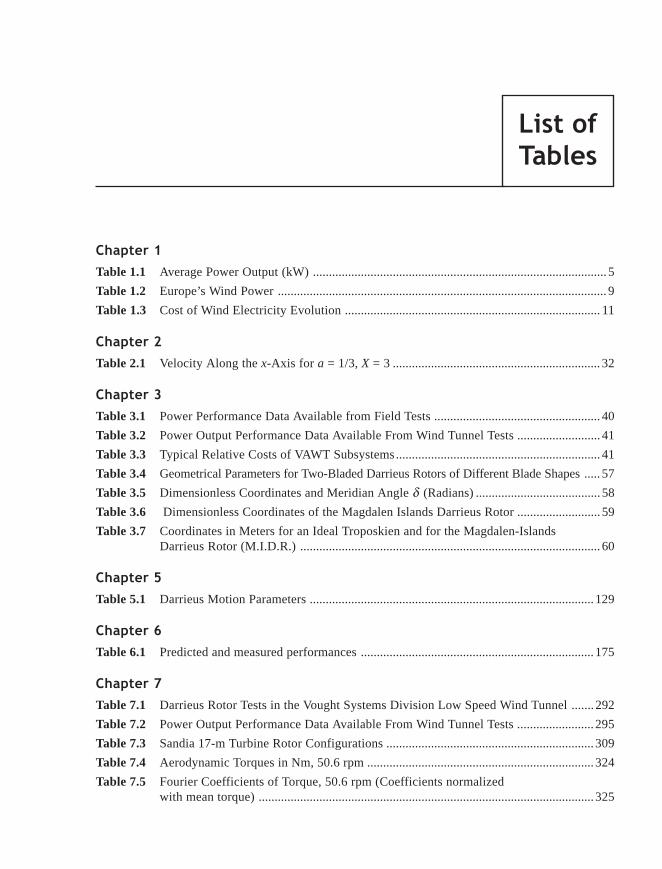
List of Tables xxiii
Table 1.1 Average Power Output (kW) ............................................................................................ 5
Table 1.2 Europe’s Wind Power ....................................................................................................... 9
Table 1.3 Cost of Wind Electricity Evolution ................................................................................ 11
Table 2.1 Velocity Along the x-Axis for a = 1/3, X = 3 ................................................................. 32
Table 3.1 Power Performance Data Available from Field Tests .................................................... 40
Table 3.2 Power Output Performance Data Available From Wind Tunnel Tests .......................... 41
Table 3.3 Typical Relative Costs of VAWT Subsystems................................................................ 41
Table 3.4 Geometrical Parameters for Two-Bladed Darrieus Rotors of Different Blade Shapes ..... 57
Table 3.5 Dimensionless Coordinates and Meridian Angle d (Radians) ....................................... 58
Table 3.6 Dimensionless Coordinates of the Magdalen Islands Darrieus Rotor .......................... 59
Table 3.7 Coordinates in Meters for an Ideal Troposkien and for the Magdalen-IslandsDarrieus Rotor (M.I.D.R.) .............................................................................................. 60
Table 5.1 Darrieus Motion Parameters ......................................................................................... 129
Table 6.1 Predicted and measured performances ......................................................................... 175
Table 7.1 Darrieus Rotor Tests in the Vought Systems Division Low Speed Wind Tunnel ....... 292
Table 7.2 Power Output Performance Data Available From Wind Tunnel Tests ........................ 295
Table 7.3 Sandia 17-m Turbine Rotor Configurations ................................................................. 309
Table 7.4 Aerodynamic Torques in Nm, 50.6 rpm ....................................................................... 324
Table 7.5 Fourier Coefficients of Torque, 50.6 rpm (Coefficients normalizedwith mean torque) ......................................................................................................... 325
List_Tables.p65 19/11/2009, 13:2823

xxiv List of Tables
Table 8.1 Ohio State University Wind Tunnel Tests .................................................................... 330
Table 8.2 34 Meter Wind Turbine Blade Data ............................................................................. 334
Table 8.3 Performance Comparison Between Cam-bered and Symmetrical Blade Sectionof the Sandia 5-Meter Research Turbine ...................................................................... 349
Table 9.1 Rotor Mass and Rotor Size ........................................................................................... 361
Table 9.2 Advantages of Two or Three Blades ............................................................................ 364
Table 9.3 Darrieus Wind Turbine Design Alternatives ................................................................ 375
Table 9.4 Darrieus Wind Turbine Improvements ......................................................................... 376
Table 9.5 Advantages and Disadvantages of HAWTs and VAWTs ............................................. 378
Table 9.6 VAWT Aspect Ratios .................................................................................................... 379
Table 9.7 Area Required for Wind Plants ..................................................................................... 381
Table 10.1 Survey on Energy Research Priority ............................................................................ 388
Table 10.2 Environmental Aspects versus Type of Wind Turbine ................................................. 389
Table 10.3 Carbon dioxide (CO2). The Leading Greenhouse Gas ................................................. 395
Table 10.4 Sulfur Dioxide (SO2). The Leading Precursor of Acid Rain ....................................... 395
Table 10.5 Nitrogen Oxides (NOx), Another Acid Rain Precursor and the LeadingComponent of Smog ..................................................................................................... 395
List_Tables.p65 19/11/2009, 13:2824

Wind Energy 1
WIND is the movement of the air between high pressure and low pressure regions in theatmosphere, caused by the uneven heating of the earth’s surface by the sun. When the air abovehot surfaces is heated, it rises, creating a low pressure zone. The air surrounding higher pres-sure zones flows toward the low pressure area, creating wind. For this reason, sometimes windenergy is called “indirect solar energy.”
Wind varies with time in intensity and direction, and the potential of a wind site isgenerally evaluated as a function of the annual average wind speed. Wind speeds can becalculated for other periods to determine hourly, daily or monthly averages. Winds vary withaltitude and wind speed is also affected by ground features such as hills. The variation of windspeed with altitude is due to friction between air movement and the earth’s surface (theatmospheric boundary-layer). All weather offices report the wind speed at a standard height of10 meters above ground. Wind near the ground gathers speed to climb a hill, then slows (andsometimes becomes very turbulent) on the far side of the hill. The wind speed strength anddirection are measured by anemometers.
The depletion of global fossil fuel reserves combined with mounting environmental concernhas served to focus attention to the development of ecologically compatible and renewablealternative energy sources. The harnessing of wind energy is a promising technology able toprovide a portion of the power requirements in many regions of the world. Wind generators area practical way to capture and convert the kinetic energy of the atmosphere to either mechanicalor, more significantly, electrical energy.
The term WINDMILL is applied to the wind-powered machine that grinds (or mills) grain.Modern machines are more correctly called WIND TURBINES because they can be used for avariety of applications, such as generating electricity and pumping water.
Windmills have a very simple design based on the drag-device that relies on different airresistance on the front and back of the rotor section to cause rotation.
An interesting and well documented survey concerning historical development of windmillsis given in “Wind Turbine Technology” (ASME Press, 1994, D.A. Spera, editor), Ref. [1.1].
The most efficient way to convert wind energy into electrical or mechanical energy isoffered by wind turbines that operate as a lifting-device. Wind turbines are classified into twocategories, according to the direction of their rotational axis: Horizontal-Axis Wind Turbines
Chap_01.p65 18/11/2009, 10:281

2 Chapter 1
(HAWT) and Vertical-Axis Wind Turbines (VAWT). Horizontal-axis wind turbines capturekinetic wind energy with a propeller type rotor and their rotational axis is parallel to the direc-tion of the wind (Fig. 1.1). Vertical-axis wind turbines use straight or curved bladed (Darrieustype) rotors with rotating axes perpendicular to the wind stream. They can capture wind fromany direction (Fig. 1.2). The most popular wind turbine systems are of the “propeller type,” butthe VAWTs have not yet benefited from the years of development undergone by HAWTs. Thesetwo kinds of wind machine are compared in Chapter 9.
Figure 1.1 Components - Upwind rotor and downwind HAWT rotor [Ref. 1.1]
Both HAWTs and VAWTs have about the same ideal efficiency but the horizontal-axis wind tur-bine is more common. It has the entire rotor, gearbox and generator at the top of the tower, andmust be turned to face the wind direction. The VAWT accepts wind from any direction, and itsheavy machinery is at ground level. This is more convenient for maintenance, particularly onlarge units or when operating in potential icing conditions.
Both types of wind turbines have the same general components:
- a rotor to convert wind energy into mechanical power,- a tower to support the rotor,- a gearbox to adjust the rotational speed of the rotor shaft for the electric generator or
pump,- a control system to monitor operation of the wind turbine in automatic mode, including
starting and stopping,- a foundation (sometimes aided by guy wires) to prevent the turbine from blowing over
in high winds.
Chap_01.p65 18/11/2009, 10:282

Wind Energy 3
Upper Bearing
Upper Hub
Central Column
Cables
Lower Hub
Lower Bearing
Support Stand
Power Train
Equipment Station
RotorFoundation
CableFoundation
GroundLevel
Clearance
Tensioner
RotorHeight
RotorDiameter
Figure 1.2 VAWT of Darrieus type [Ref. 1.1]
The size of a wind turbine is measured in terms of swept area, or surface area swept by therotating blades. The swept area of the rotor is calculated from the diameter of the rotor by:S = 0.785 D2 for HAWTs or by S = 1.000 D2 for typical VAWTs with an aspect ratio (height/diameter) of 1.5.
The control system of wind turbines is connected to an anemometer that continuouslymeasures wind speed. When wind speed is high enough to overcome friction in the drive train,the control system allows the turbine to rotate, producing limited power. This is the “cut-in”wind speed, usually about 4 or 5 m/s. Wind turbines normally have a “rated wind speed,”corresponding to maximum output power. Typically, the rated wind speed is about 10-12 m/s.If wind speed exceeds rated wind speed, the control system prevents further power increasesuntil “cut-out” wind speed is reached, at approximatively 25 m/s.
VAWTs are generally classified according to aerodynamic and mechanical characteristics,or the lifting surfaces, or the movement of the blades of the rotor, about a vertical-axis along apath in a horizontal plane. Today, there are four classes of VAWTs (Fig. 1.3):
a) the articulating straight-blade Giromill;b) the Savonius rotor, a mostly drag-driven device;c) the variable-geometry Musgrove, which permits reefing of the blades; and,d) the fixed-blade Darrieus rotor.
Vertical-axis wind turbines (VAWTs) have been studied by various researchers using modernanalysis techniques. Common examples of these vertical-axis wind turbines are the Savoniusand Darrieus turbines. In 1968, South and Rangi, from the National Research Council ofCanada, reintroduced the Darrieus rotor concept. Since then, many analytical models predictingthe aerodynamic performance of this type of wind turbine have been formulated.
Chap_01.p65 18/11/2009, 10:283
Extrait distribué par Presses Internationales Polytechnique

State of the Art of Vertical-Axis Wind Turbines 15
The earliest practical wind machines were the “Panemones” (examples: Persian vertical-axis windmill in Sista n, A.D. 1300 and Chinese vertical-axis windmill, A.D. 1219). These ma-chines were of vertical-axis type driven by drag forces with a multi-bladed rotor operating atvery low tip-speed ratios (much less than unity), which explains their poor efficiency. In spiteof the simple design, the panemones need large amounts of material, are not able to withstandhigh wind loads and thus have not proven cost-effective.
! "!#
This concept was conceived as a “train” of vehicles, each vehicle supporting rotatingcylinders mounted vertically on its flat-bed, moving to work on a circular track; each cylinderbeing driven by an electrical motor [2.1]. The Madaras rotor was designed on the principle ofthe Magnus effect known since the 1850s: the circulation induced around a rotating cylinderresults in a lift force perpendicular to the flow direction as well as to the axis of the cylinder.On the side of the cylinder, where the flow and the cylinder are moving in the same direction,boundary layer separation is completely eliminated while on the opposite side a significant partundergoes separation. In 1933, Madaras conceived a plan for a large-scale test (for a 40 MWplant) that required building a full-scale rotating cylinders of 27.4 m hight and 8.5 m diametermounted on a stationary platform in order to measure the forces due to the Magnus effect (seeFig. 2.1).
Figure 2.1 The Madaras concept for generating electricity using the Magnus effect [2.1]
Chap_02.p65 12/11/2009, 08:5315

16 Chapter 2
The Magnus effect would propel the cars around the track and drive generators connectedto the car axles. The Madaras concept for generating electricity using Magnus effect did notsucceed because of mechanical complexity: the need to reverse direction of the cylinder at eachend of the oval track, poor aerodynamic design (low “tip speed” with low aerodynamic effi-ciency), mechanical losses (high track loads and overturning moments), lower wind speeds nearthe ground and electrical losses.
"$%
Nomenclature
As = Savonius turbine swept area, m2
CP = wQ/(q•V•As ), power coefficientC*
P = wQ/[q•V• (4rH)], normalized power coefficientCQ = Q/(q•V•As), torque coefficientC*
Q = Q/[q• (4rH)(2r)], normalized torque coefficientd = 2r, bucket diameter, mH = rotor height, mN = number of bucketsp• = freestream static pressure, PaQ = turbine torque, N·mQf = friction (tare) torque, N·m (Eq. 2.12)
q• =1
22ρV∞ , freestream dynamic pressure, Pa
R = rotor radius of rotation (see Figs 2.6 and 2.7)(if s/d = 0, R = 2r, see Fig. 2.2)
Re• = rV•/m•, Reynolds number per unit length, m-1
r = bucket radius (see Figs 2.6 and 2.7), ms = bucket gap width (see Figs 2.6 and 2.7), ms/d = gap width ratioV• = V• (1 + x ), freestream velocity, m/sa = azimuthal angle (see Fig. 2.2), degL = Rw/V• , turbine tip-speed ratiol = 2rw/V• , bucket tip-speed ratiox = wind tunnel blockage factorq = bucket angular position (see Figs 2.6 and 2.7), degm• = freestream viscosity, kg/(m·s)r = freestream density, kg/m3
w = turbine rotational speed, rad/s
Subscripts
u = uncorrected for blockage• = freestream conditions
Chap_02.p65 12/11/2009, 08:5316

State of the Art of Vertical-Axis Wind Turbines 17
Another vertical-axis machine based on the low lift-to-drag ratio is the Savonius rotornamed after its Finnish inventor [2.1-2.3]. The Savonius rotor has an “S-shaped” cross-sectionand appears as a vertical cylinder sliced in half from top to bottom. It operates as a cupanemometer with the addition that wind is allowed to pass between the bent sheets (or buckets).The Savonius rotor has been studied using wind tunnel tests by several researchers since the1920s [2.4-2.12]. Generally speaking, Savonius rotors can reach maximum power coefficient of30%. Moreover, it is not efficient with respect to weight/unit power output since it wouldrequire as much as 30 times the surface to output the same power as a conventional windturbine. For this reason, the Savonius machine is only useful and economical for small powerrequirements such as water pumping, driving a small electrical generator, providing ventilation,and providing water agitation to keep stock ponds ice-free during winter. It is also commonlyused as an ocean current meter. The technology required to design and manufacture a Savoniusrotor is very simple and is recommended for applications in developing countries or in isolatedareas without electrical power. A simple Savonius rotor can be manufactured by cutting an oilbarrel in half, inverting one of the halves, and welding the two pieces together in a S-shapedcross-section.
Figure 2.2 Savonius rotor - Calculation scheme
&
A mathematical model based on the pressure drop on each side of the blades was proposedby Chauvin et al. [2.13] to evaluate the power of a two-bucket Savonius rotor with a gap spac-ing s/d = 0. From Fig. 2.2, if
w a= k is the instantaneous rotation vector and, due to the sym-
metry of the Savonius rotor, α ω= = constant, then the torque is given by:
Q OM F ki
i
= × ⋅∑ e j (2.1)
This sum has two components:
a) the first is associated with the retreating blade, a driven component, QM
b) the second is associated with the advancing blade, a resistant component, QD
Q Q QM D= + (2.2)
Chap_02.p65 12/11/2009, 08:5317

The great majority of wind turbines in the world are aerodynamically improved versions ofthe traditional horizontal-axis propeller-type device. Over the past two decades, the Darrieustype vertical-axis wind turbine (VAWT) has undergone considerable research and significantengineering development. However, it did not benefit from R&D as much as propeller-typemachines.
The Darrieus wind turbine was patented by the U.S. Patent Office in the name of G.J.M.Darrieus in 1931 [3.1]. The Darrieus patent states that each blade should “have a streamlineoutline curved in the form of skipping rope.” In other words, the Darrieus rotor has curvedblades that approximate the shape of a perfectly flexible cable, of uniform density and cross-section, hanging freely from two fixed points; under the action of centripetal forces such a shapeminimizes inherent bending stresses. This blade shape is called Troposkien (from the Greekroots: trots, turning and sXOLuLOu, rope; or “turning rope”) pure Troposkien shape (gravityneglected) does not depend on angular velocity. The first known wind tunnel measurementsof Darrieus wind-turbine performance were carried out by R.S. Rangi and P. South of theNational Research Council of Canada, [3.2, 3.3]. Later measurements included fundamentalinvestigations of the number of blades, the rotor’s solidity, and the effects of spoilers andaerobrakes. In the early 1970’s, engineers at the National Research Council of Canada (NRC)independently developed a similar concept of VAWT by assuming an approximate shape of acatenary for the curved blades.
In Great Britain, the H-type or Musgrove rotor VAWT was introduced by Vertical-AxisWind Turbines Limited [3.4]. The Musgrove rotor is straight bladed and can be reefed to providespeed control. Two prototypes of H-type machine were built in 1986: a 25-m rotor sponsoredby the U.K. Department of Energy, and a 14-m machine funded by Tema SpA of Italy. The HM-Rotor-300, another straight-bladed Darrieus rotor, was manufactured by the Heidelberg MotorCompany. An interesting H-Type prototype was tested in 1994 at Kaiser-Wilhelm-Koog WindTest site; this rotor has no gearbox and its low rotor speed reduces noise [IEA 1992].
The Darrieus curved blade rotor has been developed and commercialized mainly in NorthAmerica at institutions such as the National Research Council of Canada and by companies suchas FloWind Corp. and Vawtpower in the U.S. and Indal Technologies Inc., Lavalin Inc. andAdecon Inc. in Canada. A detailed survey and bibliography on the vertical-axis wind turbinesis presented in Ref. [3.5]. Sandia National Laboratories (SNL) deployed considerable effort forthe research and development of the curve-bladed Darrieus rotor. Thus, in 1974 SNL built a5-m diameter research VAWT, followed by a 17-m diameter rated at 60 kW in 1977 [3.6-3.18].
Chap_03.p65 19/11/2009, 15:4137

38 Chapter 3
A significant step in the development of larger and more efficient commercial Darrieus VAWT’swas the installation and operation of 34-m Sandia-DOE VAWT in 1987, rated at 625 kW. TheSandia 34-m turbine (Fig. 3.1) was the first curved-blade Darrieus turbine rotor originallydesigned to incorporate step tapered blades using varying blade-section airfoils and a bladeairfoil section specifically designed for VAWTs. The equator and transition sections of that ro-tor use the SAND 0018/50 airfoil section while the root sections are NACA 0021, [3.19-3.20].The test beds are designed so that configurations can be quickly and easily changed toinvestigate the basic physics of wind turbines. For example, the Sandia 34-m test bed isequipped with a variable speed drive system to permit, among other things, performance testsof new blade airfoils and blade shapes over a wide range of Reynolds numbers. Test beds arenormally operated on a limited basis and only for specific tests.
Figure 3.1 Darrieus vertical-axis wind turbine (DOE/SANDIA 34-m)(Courtesy of Sandia National Laboratories)
Chap_03.p65 19/11/2009, 15:4238

The Darrieus Wind-Turbine Concept 39
The Canadians manufactured the first large-scale Darrieus turbine rated at 230 kW with anestimated average output of 100 kW on Magdalen-Islands in May 1977. An unexpected self-start with no brakes destroyed this prototype, and a similar VAWT was installed in 1978, [3.21].Performance test data for this turbine operating at 29.4 rpm [3.22], are believed to be the firstfield data gathered on large scale Darrieus turbines that clearly show the performance in the poststall regime (at low tip-speed ratios). A complete data set for operation at 36.6 rpm could notbe obtained because high wind operation was limited to about 15 m/s. The performance dataobtained from this turbine were an important element in the design of the Indal 6400-500 kWturbine since the effects of dynamic stall were not included in performance prediction models,and peak power output was seriously underestimated by the models.
Under Sandia technical guidance and DOE support funding, Alcoa constructed four 17-m,100-kW units, two of which were grid-connected. One of these was tested successfully for over10,000 h in storm winds exceeding 120 mph, [3.23-3.25]. The performance testing of the SandiaNational Laboratories 2, 5, 17 and 34-m research turbines resulted in the most rigorous andexhaustive set of performance data and comparisons to theoretical predictions. SNL routinelypresented test and predicted data in non-dimensional form, to facilitate comparison with otherdata, including those for HAWTs.
The greatest power output measured for any Darrieus wind turbine constructed to date hasbeen from the Lavalin Eole (64 m) Research Turbine [3.26]. Built in 1986 in Cap Chat, Quebec,Canada, Eole is a two-bladed NACA 0018 rotor at fixed rotational speeds of 10 and 11.35 rpmrespectively. The maximum power output is in excess of 1.3 MW at 14.7 m/s and correspondsto 11.35 rpm. The Eole wind turbine was designed to operate in a variable speed mode up to arotor speed of 16.3 rpm with the maximum power reaching about 3.6 MW at 17 m/s and thenbeing held constant by decreasing rotor speed at higher wind speeds [3.27]. However, fatiguelife predictions showed that the turbine should be limited to 13.25 rpm with a nominal cut-outof 15 m/s (about 2 MW maximum power output) in order to operate successfully for the fiveyear duration of the energy purchase agreement.
FloWind was a leader in delivering wind generated electricity to U.S. utilities, anddesigned, manufactured and operated wind turbines from 1982 to 1997. They developed aVAWT FloWind 19-m using a two-bladed NACA 0015 operating at 51.8 rpm and producing250 kW at a wind speed of about 20 m/s, [3.28-3.29]. Drawing upon this experience, FloWinddeveloped a new generation advanced vertical-axis wind turbine, with an extended height-to-diameter (EHD) ratio. This class of advanced VAWT maximizes production from any givenwind area. In this case, an optimal balance between aerodynamic efficiency, wake loss andswept area is achieved by varying rotor height and diameter. For example, the three bladedFloWind EHD 17-m wind turbine, using a laminar airfoil SNLA 0021/50, can produce 175 kWat 51.8 rpm operating in a wind of 16 m/s, [3.30].
The power performance data available for Darrieus wind turbines from field tests in severalcountries is summarised in Table 3.1. Table 3.2 shows a few Darrieus wind turbines for whichpower output data are available from wind tunnel tests. In both cases, both the predicted powerand the aerodynamic model used for calculation are indicated.
Chap_03.p65 19/11/2009, 15:4239
Excerpt of the full publication

Aerodynamic Performance Prediction Models 65
a = velocity interference factor (Eq. 4.37)c = chord length of blade, mCDD = disk drag coefficientCN = normal force coefficientCP = average coefficient of powerCPe = elemental coefficient of power (Eq. 4.72)CT = tangential force coefficientc/R = chord-to-radius ratioD = wind turbine drag, NFN = normal force on turbine blade, N
FN* = dimensionless normal force on turbine blade
FT = tangential force on turbine blade, N
FT* = dimensionless tangential force on turbine blade
h = height of streamtube, m2H = rotor height, mL = lift force, NN = number of bladesNc/R = rotor solidity (Eq. 4.15)NLEV = number of vertically spaced blade divisions (see Fig. 4.20)NSTA = number of angular blade positions (Eq. 4.58 and Fig. 4.20)q = local relative dynamic pressure, N/m2
r = local turbine radius, mR = radius of turbine at equator, mS = frontal area of turbine (or disk area), m2
t = time, sTB = total torque, N◊◊◊◊◊m (Eq. 4.20)Te = elemental blade torque, N◊◊◊◊◊m (Eq. 4.70)Te
* = dimensionless blade torque (Eq. 4.71)TS = single blade torque, N◊◊◊◊◊m (Eq. 4.19)
V = fluid velocity, m/sdv = velocity through wind turbine disk, m/sdV = disturbance velocity, m/srV = relative fluid velocity, m/stV = tip-speed, m/sTV = tangential blade velocity at equator, m/swV = wake convection velocity, m/s
Chap_04.p65 12/11/2009, 08:5965

66 Chapter 4
V∞ = freestream velocity, m/s
W = relative velocity, m/s( )
w y = downwash velocity, m/sX = tip-speed ratioz = height with respect to equator, ma = angle of attack, degd = blade slope angle (or meridian angle), degg = vorticity, m2/sgS = shed vorticity, m2/sg t = trailing vorticity, m2/sgw = wake vorticity, m2/sG = circulation, m2/sh = r/Rq = azimuthal angle of turbine blade, degr = fluid density, kg/m3
w = angular velocity, rad-1
z = z/H
SubscriptsEQ = equator• = freestream value
Superscripts(-) = mean value(*) = dimensionless value
!"
The single streamtube model was first developed by Templin [4.1] to calculate theaerodynamic performance of a curved-blade vertical-axis wind turbine. This model is based onthe approach of the propeller or windmill actuator disk theories that assume induced velocityto be constant through the disk and related directly to wind turbine drag. The induced velocityis thus assumed to be the same through upwind and downwind faces of the rotor.
According to Glauert’s theory [4.2], the velocity through a windmill disk VD is thearithmetic mean of the undisturbed velocity V• and the velocity in the wake. The wind turbinedrag is given by
D SV V VD D= −( )∞2ρ (4.1)
where r represents the fluid density and S the disk area.
A disk drag coefficient CDD based on the dynamic pressure and the disk area is defined as:
C
D
V SDD
D
=12
2ρ (4.2)
and from equation (4.1),
CV
VDDD
= −
∞4 1 (4.3)
Chap_04.p65 12/11/2009, 08:5966
Extrait distribué par Presses Internationales Polytechnique

Aerodynamic Performance Prediction Models 67
Hence
V
VC
DDD
∞ = +11
4 (4.4)
For structural design purposes, a more convenient drag coefficient CD is based on the ambientdynamic pressure, where
CD
V SC
V
V
C
CD DD
D DD
DD
= =
=+
∞ ∞1
2 114
2
2
2ρ (4.5)
For a given wind turbine geometry and rotational speed w, the aerodynamic performance,turbine power and rotor drag are calculated using the blade element theory. In general,the curved shape of the vertical-axis wind rotor is that of a skipping rope, spinning about avertical-axis and assuming the gravity forces to be negligible. For a ratio of rotor height torotor diameter of unity, the shape can be approximated by a parabola and the blade shape isgiven by the expression:
r
R
z
H= −
1
2
(4.6)
which in nondimensional form is h = 1 - z 2, with h = r/R and z = z/H, where r is the localrotor radius and z is the height above the equatorial plane. By differentiating the relation (4.6)we can obtain the local blade slope given by angle d (Fig. 4.1).
δ ζ=
−tan 1 1
2 (4.7)
Figure 4.1 Curved blade vertical-axis wind turbine with three blades
Chap_04.p65 12/11/2009, 08:5967
Extrait distribué par Presses Internationales Polytechnique

Unsteady Aerodynamics − CFD Models 101
The environment-friendly nature of wind energy and recent advances in wind turbinetechnology have made this renewable energy source a promising alternative for the future.Although the horizontal-axis wind turbine is the most common device of its type, the Darrieusvertical-axis model has proven one of the most efficient systems of wind energy conversion. Itsmany advantages include its independence of wind direction and its simplicity. Some of themost complex and least understood phenomena in the field of Computational Fluid Dynamics(CFD) are associated with the description of the flow past rotating blades (Fig. 5.1). A majoraspect of the unsteady aerodynamics of the Darrieus rotor is dynamic stall, which occurs at lowtip-speed ratios. Its effects have a significant influence on the overall system design. Accordingto many experimental tests, the feature of dynamic stall that distinguishes it from static stall isthe shedding of significant concentrated vorticity from the leading-edge region. This vortexdisturbance subsequently sweeps over the airfoil surface causing pressure changes and resultingin significant increases in airfoil lift and large nose-down pitching that exceeds static values.
This chapter describes a two-dimensional unsteady flow analysis around an airfoil inDarrieus motion under dynamic-stall conditions (Fig. 5.2). A numerical solver based on thesolution of the Reynolds-averaged Navier-Stokes equations expressed in a streamfunction-vorticity formulation in a non-inertial frame of reference is developed. The governing equationsare solved by the streamline upwind Petrov-Galerkin finite element method (FEM). Temporaldiscretization is achieved by second-order-accurate finite differences. The resulting globalmatrix system is linearized by the Newton method and solved by the generalized minimumresidual method (GMRES) with an incomplete triangular factorization preconditioning (ILU).Turbulence effects are introduced in the solver by eddy viscosity models, namely the algebraicCebeci-Smith model and the nonequilibrium Johnson-King model. To validate the turbulentsolver, a flat plate in pure translation and a pitching NACA 0015 airfoil are used as test cases.The Johnson-King model shows better performance than the Cebeci-Smith or the k-e turbulencemodels for the pitching NACA 0015 airfoil test case. The solver is then used to simulate theflow around a NACA 0015 airfoil in a Darrieus motion (Fig. 5.1). The computed results showclearly some distinctive features of the dynamic stall on an airfoil in Darrieus motion despitethe fact that the generation of the leading-edge vortex typical for dynamic stall is not observed.
chap_05.p65 19/11/2009, 13:41101

102 Chapter 5
Figure 5.1 Airfoil in Darrieus motion
A = cross-section of the body surrounded by Bs, nondimensionalized by c2, (Fig. 5.4)A+ = constant in the law of the wall coordinate (A+ = 26 (CSM), A+ = 17 (JKM), (Eq. 5.48)B• = external boundary of B, (Fig. 5.4)Bs = internal boundary of B, (Fig. 5.4)B = computational domainCM = pitching moment coefficientCN = normal force coefficientCp = pressure coefficientCT = tangential force coefficientc = airfoil chord, me = finite element domain(e1, e2, e3) = ( )1 2 3, ,e e e
, unit vectors along x, y and z directions
FKleb = Klebanoff intermittence functiong = function defined as τ m
−1 2 , (Eq. 5.59)k = turbulent kinetic energyk* = wc/(2u∞), reduced frequencyn n nP
e e e, ,ψ ω = number of nodes associated to finite elementP = perturbation pressure, nondimensionalized by u∞
2 , (Eq. 5.59)p = pressure, nondimensionalized byR = equatorial radius, nondimensionalized by cRe = Reynolds number, Re = u•c/ns, n = unit vectors tangent and normal to boundariest = time, nondimensionalized by c/u•D t = time step, nondimensionalized by c/u•u = velocity vector, nondimensionalized by u•
2uρ ∞
chap_05.p65 19/11/2009, 13:41102

Unsteady Aerodynamics − CFD Models 103
ub = velocity vector of the non-inertial frame of reference, nondimensionalized by u•Vrel = relative velocity, nondimensionalized by u•x, y = cartesian coordinatesx = position vectora = incidence angle, deg.d = boundary layer thickness, nondimensionalized by cd* = displacement thickness, nondimensionalized by ch = normal distance from the wall, nondimensionalized by ch+ = law of the wall coordinatek = von Karman constant (k = 0.41)l = tip-speed ratio (l = WbR/u•)n = kinematic viscosity, nondimensionalized by u•cnt = turbulent eddy viscosity, nondimensionalized by u•cnti = inner eddy viscosity, nondimensionalized by u•cnto = outer eddy viscosity, nondimensionalized by u•cr = density, nondimensionalized by r•s = link parameter, (Eq. 5.57)t = Reynolds shear stressy = perturbation streamfunction, nondimensionalized by u•cY = streamfunction, nondimensionalized by u•cyb = value of the perturbation function on solid wall Bs, nondimensionalized by u•cW = vorticity function, nondimensionalized by u•/cWWWWWb = angular velocity vector of the non-inertial frame of reference,
nondimensionalized by u•/cWb = component in e3-direction of WWWWWb, nondimensionalized by u•/cw = perturbation vorticity, nondimensionalized by u•/cq = azimuthal angle, deg
e = edge of boundary layereq = equilibrium valuei = inner layerm = value at t = tmaxo = outer layert = turbulentw = wall• = freestream value
k = iteration level(¯) = mean value(·) = first total time derivative( )¢ = fluctuating value
chap_05.p65 19/11/2009, 13:41103
Extrait distribué par Presses Internationales Polytechnique

Double-Multiple Streamtube - A Practical Design Model 151
Control Volume 3 (Fig. 6.4)
Continuity equation:
ρ ρ ρ ρa V aV AV a Vw0 ∞ = = ′ = ′′ (6.6)
Momentum equation:
T T AV V Va + = ′ − ′′( )2 ρ (6.7)
Bernoulli’s equations:
from 0 to 1,
p V p V∞ ∞+ = +1
2
1
22
12ρ ρ (6.8)
from 2 to 3,
p V p V22
321
2
1
2+ = + ′ρ ρ (6.9)
from 4 to 5,
p V p V42 21
2
1
2+ ′ = + ′′∞ρ ρ (6.10)
Control Volumes 4 and 5 (Fig. 6.4)
Momentum equation: p p a Ta1 2−( ) = (6.11)
p p A T3 4 2−( ) = (6.12)
Drag Coefficient of the Upstream Actuator Disk
If one combines equations (6.4) and (6.5) one gets
p p V V V1 2− = −( )∞ρ Ω (6.13)
and from equations (6.2) and (6.3)
p p V V1 22 21
2− = −( )∞ρ Ω (6.14)
The combination of equations (6.13) and (6.14) gives
VV V
=+∞ Ω
2(6.15)
One obtaines from equations (6.14) and (6.11)
T V V aa = −( )∞1
22 2ρ Ω (6.16)
Substituting the value of VW from equation (6.15) and the value of a from equation (6.6) oneobtaines
T V V V Aa = ′ −( )∞2ρ (6.17)
Substituting the results obtained in equation (6.6) and knowing that T1 = D1 results in
D A V V V1 2= −( )∞ρ (6.18)
Taking into account (6.6) and (6.11), and substituting (6.17) in (6.5).
chap_06.p65 12/11/2009, 09:06151
Excerpt of the full publication
Extrait distribué par Presses Internationales Polytechnique

152 Chapter 6
Defining the drag coefficient CD1 as
C
D
V AD1
1
212
=∞ρ (6.19)
one obtains
CV
V
V
VD14 1= −
∞ ∞
(6.20)
as the drag coefficient of the upstream actuator disk.
Drag Coefficient of the Down-stream Actuator Disk
If one substitutes equations (6.17), (6.12) and (6.6) into the momentum equation (6.7) ofcontrol volume, (Fig. 6.4), one gets
′′ = ′ ± ′ + − ′ −( ) + ′ +( )[ ]∞ ∞ ∞V V V V V V V V V V2 1 24 2 (6.21)
Knowing that T2 = D2 and combining equations (6.17) and (6.7) one obtains
D AV V V V2 2= ′ − − ′′( )∞ρ (6.22)
defining the drag coefficient CD2 as
C
D
V AD2
2
212
=∞ρ (6.23)
and combining it with equation (6.21) results in
CV
V
V
V
V
V
V
V
V
V
V
V
V
V
V
VD22 2 2 4 1 1 1
2 1 2
= ′ − ′ + ′
+ ′ + − ′ −
+
−
∞ ∞ ∞ ∞ ∞ ∞ ∞ ∞ (6.24)
as the drag coefficient of the down-stream actuator disk.
We thus obtain the drag coefficient for each actuator disk. Note that the drag coefficient ofthe upstream actuator disk, CD1
, is a function of only V/V• and that of the down-stream, CD2,
is a function of V/V• and V ¢/V•.
The overall drag of the wind turbine is the summation of the drag of the upwind anddownwind actuator disks. Thus, in coefficient form:
C C CD D D= +1 2 (6.25)
There are some theoretical limitations to the values of CD1 and V/V•. One can invert
equation (6.20) and obtain the velocity ratio V/V• as a function of the drag coefficient CD1
V
VCD
∞= + −1
2
1
21
1 (6.26)
The maximum theoretical value of CD1 is 1.0 at V/V• = 0.5.
chap_06.p65 12/11/2009, 09:06152
Excerpt of the full publication
Extrait distribué par Presses Internationales Polytechnique

Double-Multiple Streamtube - A Practical Design Model 153
) (!!%"&
For simplicity’s sake, we consider the wind turbine geometry approximated by a parabolaat a diameter/height ratio of unity. Thus the rotor blade shape is given by the expression
η ζ= −1 2 (6.27)
with h = r/R, z = z/H, where r is the local radius and z is the height above the rotor equatorialplane.
The local blade slope d representing the angle between the normal to the blade chord planeand the horizontal plane is found by differentiation of equation (6.27) and is given as
δζ
=
−tan 1 1
2 (6.28)
The local angle of attack is determined from geometric considerations on a blade elementand from a velocity diagram of the local relative velocity (Fig. 6.5). The general expression forangle of attack given in reference [6.5] is
αθ δ α θ α
θ θ δ=
− −( )−( ) +
−sincos cos cos sin sin
sin cos cos
1 0 0
2 2 2
X
X(6.29)
This equation suggests the possibility of on asymmetrical section or a symmetrical sectionwhere the chord line is not tangential to the circle of rotation (or blade flight path), a0 π 0, [6.6].
Wind Turbine Axis
V sin q
r
q
d
Wa
wr 90 - qo
V
V cos cosq d
V cos q
Horizontal Plane
d
Figure 6.5 Relative velocity and angle of attack
Airfoil CharacteristicsWe assume that two dimensional airfoil characteristics can be used for the local blade
element lift and drag coefficients. Care must be taken to use airfoil characteristics appropriateto the wind turbine blade Reynolds number. It is convenient for further calculations to resolvethe respective drag and lift coefficients into a normal force coefficient CN and a thrust forcecoefficient CT as shown in Figure 6.6.
chap_06.p65 12/11/2009, 09:06153

154 Chapter 6
CL
CL cos a
CD sin a
CD
CD cos a
CL sin a
aW
Figure 6.6 Force coefficients of a blade element airfoil
C C CN L D= +cos sinα α (6.30)
C C CT L D= −sin cosα α (6.31)
The thrust coefficient CT is considered positive when directed forward along the airfoil chord.
Drag and Side-Force Coefficients
A blade element of chord c and height dz has a plan area cdz/cosd (Fig. 6.7). This area issubjected to an elemental normal force dN and elemental thrust force dT.
dNC qc
dzN=cos δ
(6.32)
dTC qc
dzT=cos δ
(6.33)
where q is the local relative dynamic pressure given by:
q W= 1
22ρ (6.34)
The instantaneous elemental drag and side-force, when the forces are resolved into direc-tions parallel and perpendicular to the ambient wind direction, (Fig. 6.8) are:
dD V dN dTparallel to cos cos sin∞( ) = ( ) +δ θ θ (6.35)
dL V dN dTperpendicular to cos sin cos∞( ) = − ( ) +δ θ θ (6.36)
Substituting equations (6.32) and (6.33) into equations (6.35) and (6.36) we obtain theelemental drag and side-force:
dD qc C C dzN T= +
cos
sin
cosθ θ
δ (6.37)
dL qc C C dzN T= − +
sin
cos
cosθ θ
δ (6.38)
chap_06.p65 12/11/2009, 09:06154

Aerodynamic Loads and Performance Tests 269
Figure 7.3 Blade force measurement
Normal and Tangential Blade Forces
The experimental data for normal force and tangential force coefficients F+N and F+
Trespectively were compared with VDART2 predictions (Eqs. 4.32) and it became apparent thatthe dynamic effects presented in Ref. [7.2] were significant. At the tip-speed ratio of 2.5,dynamic stall was found to be important. At the highest tip-speed ratio of 7.5, added masseffects and pitching circulation were found to be important, while at the moderate tip-speedratio of 5.0, both effects played a role.
Chap_07.p65 12/11/2009, 09:10269
Extrait distribué par Presses Internationales Polytechnique

270 Chapter 7
Normal blade force coefficient data should be corrected by subtracting the centrifugal for-ces induced in the experiment. This correction is given by Strickland et al [7.2]:
∆Ft
cNB
f
bt
bf
+ = −134 2.ρρ
λ (7.3)
where rB/rf is the blade density to fluid density ratio, t/c is the thickness to chord ratio, andbt/bf is the total blade length to the blade length immersed in the fluid ratio. The numericalcoefficient is equal to twice the airfoil cross sectional area divided by the thickness chordproduct. This correction is insignificant at the lower tip-speed ratios producing a downwardshift in the FN
+ curve of only 0.48 at a tip-speed of 2.5. At a tip-speed ratio of 7.5, the shift isequal to about 4.29.
Figure 7.4 Blade force data for a two-dimensional rotor (Re = 40,000, N = 2, l = 7.5, towtank data, --- quasi-steady model, - dynamic model)
Chap_07.p65 12/11/2009, 09:10270
Excerpt of the full publication
Extrait distribué par Presses Internationales Polytechnique

Aerodynamic Loads and Performance Tests 271
The blade force measurements on two dimensional rotor, having two blades (N = 2), arecompared with analytical prediction and results at a tip-speed ratio of 7.5 are shown in Fig. 7.4.At this tip-speed ratio, only the dynamic effects are present; dynamic stall does not occur. Ascan be noted from this figure, these dynamic effects produce a significant downward shift in theFN
+ curve and an amplification in the FT+ curve. It is apparent that these effects should be
included in the analytical model.
The agreement between the VDART2 model and this experiment is reasonably good inlight of the uncertainties. The hump seen in the experimental curve near 1080 deg + 270 degmay be partially due to misalignment errors in the blade mounting. Errors on the order of 1 deg
Figure 7.5 Blade force data for a two-dimensional rotor (Re = 40,000, N = 2, l = 2.5, towtank data, --- quasi-steady model, - dynamic model)
Chap_07.p65 12/11/2009, 09:10271
Excerpt of the full publication

272 Chapter 7
in the blade angle of attack could cause this level of deviation from the analysis. A slight phaseshift is also apparent between analysis and experiment. The exact cause of this shift is unknown,but may be partially due to the time step size used in the analytical model. Since calculationsare spread over a particular time step which represents about 15 deg of rotor rotation, the shiftdue to this cause could potentially reach 15 deg.
Results at a tip-speed ratio of 2.5 illustrated in Fig. 7.5 show the dominant effects due todynamic stall. It is apparent from Fig. 7.5 that some sort of correction to the quasi-steadyanalysis is required to adequately predict the experimental results. Strict application of themethod yielded values of FT
+ which were on the order of 3.5. The modified Boeing-Vertoldynamic-stall model [7.9] (by adopting the time delay coefficients) does appear to yieldimprovement in prediction of normal and tangential forces, but the results are not totallysatisfying.
At a moderate tip-speed ratio of 5.0 each of the dynamic effects (added mass, pitchingcirculation and dynamic stall) are important. The effects of dynamic stall are strongly relatedto the chord to radius ratio, c/R, as are other dynamic effects which are strongest for large c/Rvalues. The two-dimensional experiment conducted by Strickland represents a rather large c/Rvalue equal to 0.15, as opposed to about 0.05 for most full-scale rotors. Thus this experimentalconfiguration represents a rather severe test with regard to dynamic effects.
Wake StructureResults from the two-dimensional tow tank experiment, as well as results from the wake
measurements behind a three-dimensional Darrieus turbine made by Vermeulen [7.10], will becompared with analytical results. The test conditions at Texas Tech University [7.2] are verydifferent for the two sets of experiments representing a two-dimensional low turbulence levelflow, while the measurements made by Vermeulen represent a three-dimensional high turbu-lence level atmospheric flow.
For two-dimensional rotors, velocity profiles were taken at one and two rotor diametersdown-stream of the rotors used in the tow tank test series. These experimental data werecompared with the VDART computer code, and also with the simple momentum model [7.11].The simple momentum model can be used to estimate the fully developed wake by multiplyingthe velocity defect computed for the "actuator" disk by a factor of two. The wake behind aDarrieus turbine reaches a fully developed condition within about one rotor diameter down-stream of its vertical-axis.
The level of agreement between both numerical and the experimental data is reasonablygood so long as the perturbation velocities are small [7.2]. However, the momentum model isunable to predict a reasonable wake velocity profile for cases where the perturbation velocityapproaches 1.0. It is well known that the momentum model breaks down for these cases.
The vortex model predicts reasonable results for the average streamwise velocity perturba-tions at the higher tip-speed ratios and for larger rotor solidities. This numerical model is alsocapable of predicting both instantaneous streamwise and lateral perturbation velocities asillustrated in Figs 7.6 and 7.7.
Chap_07.p65 12/11/2009, 09:10272

Innovative Aerodynamic Devices for Darrieus Rotor 333
In 1984, Klimas [8.6] from Sandia National Laboratories has performed the first tests ofNLF blades on the Sandia 5-m research wind turbine. The test results on SAND 0015/47 andthe SAND 0018/50 airfoils were compared to results for the NACA 0015 bladed version of5-m turbine. The following conclusions were reached:
a) NLF blade sections reduce the peak power output while maintaining the performance atlower wind speeds (Figs 8.5 and 8.6).
b) The power coefficient was nearly constant over a wide range of tip-speed ratios and the cut-in tip-speed ratio was the same. The unfavourable result (cut-in tip-speed ratio) for SAND0018/50 can be explained by low Reynolds number effect and an excessive flow separation.
Figure 8.5 Performance of the Sandia 5-m turbine with NACA 0015 and SAND 0015/47airfoil sections
Chap_08.p65 12/11/2009, 09:11333

334 Chapter 8
Figure 8.6 Power coefficient versus tip-speed ratio for the Sandia 5 meter diameter test tur-bine with SAND 0015/47 and NACA 0015 blade sections
Further testing was carried out by Sandia using the 17-m research turbine with two bladeshaving chords of 0.61 m, [8.7,8.8]. The blade sections near the root used the NACA 0015 airfoiland the SAND 0018/50 airfoil was used in the centre portion. Figure 8.7 shows the test resultsfor this configuration and for the same turbine equipped with blades having the NACA 0015airfoil only. The stall regulation effect at 50.6 rpm is clearly shown.
The Sandia 34-m turbine [8.9] was the first curved blade Darrieus turbine rotor originallydesigned to incorporate step tapered blades using varying blade section airfoil and a bladeairfoil section specifically designed for VAWTs. The equator and transition sections of thatrotor use the SAND 0018/50 airfoil section while the root sections are NACA 0021. The bladesections were fabricated of multiple aluminium alloy extrusions joined along the span and theblade design details are presented in Table 8.2.
The five blade sections per blade were joined together using external joints. The chordchanges abruptly at the joints (hence the term step tapered blade) along with a slopediscontinuity. Aerodynamic smoothing coumpound was used to cover recessed bolt heads, tofair portions of the external blade-to-blade joints into the blades and to protect surface mountedtransducers and their associated wiring and completion units. The blades were painted.
Table 8.2 34 Meter Wind Turbine Blade Data
Blade Section Length of Section Airfoil Section Airfoil Chord No. of Extrusions
Equatorial, curved 19.1 m, 1 per blade SAND 0018/50 0.91 m 2
Transition, curved 7.5 m, 2 per blade SAND 0018/50 1.07 m 2
Root, Straight 9.2 m, 2 per blade NACA 0021 1.22 m 3
Chap_08.p65 12/11/2009, 09:11334
Excerpt of the full publication

Innovative Aerodynamic Devices for Darrieus Rotor 335
DOE/SANDIA17-m VAWT50.6 rpm
RotorNACA 0015Hybrid
-10
0
10
20
30
40
50
60
70
80
90
0 10 20 30 40 50 60
Pow
er,
(kW
)P
Wind speed, (mph)VEQ
Figure 8.7 Sandia 17 meter research turbine measured performance operating with the SAND0018/50 airfoil section
The first rotor power test results [8.10, 8.11] compared with the predicted performanceusing the double-multiple streamtube approach and a modified Gormont dynamic-stall modelexcept for the NLF sections of the blade. The discrepancy between test data and predictionsmay be explained by several factors, as well as: the use in calculation of 2-D experimental CLand CD obtained in quiet (low turbulence) and in linear flow wind tunnel are questionable. TheSandia SNLA 0021/50 airfoil produces an earlier transition and no laminar separation with alarger drag than expected by 2-D experiment [8.12].
The paint of the blades had flaked at the leading edge of the NLF blade sections, whichcreated forward facing steps near the leading edge with a height of approximately 0.25 mm.These were believed to be very significant boundary layer trips which could be expected todestroy the laminar flow over the blade and result in higher drag and lower lift than predicted.To correct the problem, the paint was removed from the leading edges for a distance of at leastone cm or until an area was reached where the paint adhered well. The bare metal was then fairedsmoothly into the remaining painted surface with emery paper. Power output performancesubsequently improved greatly in high wind and modestly in low wind, as shown in Fig. 8.8(Berg, Klimas and Stephenson [8.11]). The improvement in low wind was due to a decrease inCD0 while the improvement at high winds was due to a decrease in CD0 and an increase in CLmax.
Chap_08.p65 12/11/2009, 09:11335
Excerpt of the full publication

336 Chapter 8
0 5 10 15 20 25 30 35 40 45
Equatorial wind speed, (mph)VEQ
0
50
100
150
200
250
300
CARDAA: 28.0 rpmMeasured: 28.3 rpm
L. E. peelingMeasured: 28.3 rpm
L. E. sanded
DOE/SANDIA 34-mTest bed performance
Po
wer
,(k
W)
P
Figure 8.8 Sandia 34 meter turbine performance before and after clean up of paint flaking
Figure 8.9 34 meter test turbine performance without fairing
Chap_08.p65 12/11/2009, 09:11336

Future Trends Design of Darrieus Wind Turbine 363
Figure 9.3 FloWind Darrieus turbines
Chap_09.p65 12/11/2009, 09:12363

364 Chapter 9
The number of blades and the choice of blade chord can also be influenced by the choiceof blade construction. The largest available single aluminium alloy extrusion is approximately0.76 m, so for machines exceeding 25 m in diameter combined multiple extrusions or anincreased number of blades may be possible. The Adecon SL55 has four blades, partly becauseof the availability of extrusions from earlier machines.
Table 9.2 shows the advantages and disadvantages of two vs three blades. This is anexample of the laws of structural- and aerodynamics combined with overall economics. Therotor with the lowest solidity will usually capture the most energy for the least installed massadds cost. However, structural considerations favour blades with larger chord since the elasticmodule (controlling stress for a given bending moment) increases with the square of the chord.The logical outcome of this would lead to a one-bladed machine which confronts the designerwith rotor balance problems.
The additional complexity of erecting a three-bladed rotor has also favoured the two-bladedrotor. The only circumstances which might lead to a cost-effective three-bladed rotor is thedemonstration that the former has considerably more favorable structural dynamics than thelatter.
In 1978, Ljungstrom [9.26] proposed a series of rotors incorporating double blades con-nected by a number of spacers. The advantage of this concept is that its combined in-planestiffness and strength is many times greater than a single blade and survival wind stability canbe achieved with relatively small blades. Disadvantages are that the second blade does notcontribute to the performance as if it were a single blade; the parasitic loss at the intersectionsof the blades and the spacers can be considerable; and the blades could be costly to manufacture.
Table 9.2 Advantages of Two or Three Blades
Item Three Blades Two Blades
Construction cost Higher Lower
Assembly costs Higher Lower
Choice of fabrication techniques Better Poorer
Strength/weight ratio Poorer Better
Torque ripple Better Poorer
Structural dynamics Better Poorer
& ' '
The most Darrieus rotor blades used a NACA 00XX symmetrical airfoil due to its high lift,good stall characteristics combined with low drag and the ready availability of performancedata. Earlier rotors used mainly the thinner NACA 0012 and NACA 0015 airfoils. However, therequirements of increased flatwise strength has led some manufacturers to choose NACA 0018airfoils.
Chap_09.p65 12/11/2009, 09:12364

Future Trends Design of Darrieus Wind Turbine 365
The cost effectiveness of wind turbines is depending on maximizing energy capture whileminimizing the cost of all components, including the drive train, Kadlec [9.27, 9.28]. Thismeant minimizing the peak low-speed torque by avoiding airfoils with high lift coefficients andled to the development of a family of airfoils at Ohio State University based on laminar flowover the leading section of the blade and earlier stalling [9.29]. These airfoils were tested on theDOE 100 kW rotor and were included in the Sandia/DOE 34-m Test Bed [9.30]. While severalstudies have confirmed the potential improvements to be obtained by using the laminar flow, or“tailored” airfoils [9.31], test results have been mixed. The maximum power appears to havebeen successfully attenuated except in the presence of insect accumulation, when attenuationwas diminished.
The performance of HAWTs has increased considerably over the past decade and, they canreach a power coefficient of 0.49 and, in a 8.04 m/s mean (Rayleigh) wind speed, for an annualelectrical production of 1500 kWh/m2. This resulted from improved airfoils, variable speed ormulti-speed operation and more efficient drive trains.
These levels of performance cannot currently be matched by the Darrieus rotor although thegap is not great. The aerodynamic efficiency of the Darrieus wind turbine may be improved byusing blade airfoils that reduce drag. These might be improvements on the attempt at laminarflow blades designed at Ohio State University [9.29] and used on the Sandia 34-m Test Bed (seeChapter 8).
( #
The rotor speed is mainly controlled by the wind regime, the solidity, and the machinepower rating. It is possible to extract more energy with the least blade area by increasing therotor speed. However, this can lead to blades that will not withstand the aerodynamic andinertial loads; this is the case of the NRC/Hydro-Quebec (Magdalen Islands) 24-m machinewhich was run at speeds of between 28 and 36 rpm. The same configuration ran at 45 rpm andwas rated at 500 kW (to become the Indal 6400). This was satisfactory for developers wishingto increase machine ratings, but was effective in increasing total energy capture only insufficiently high wind regimes.
Increasing rotor speed decreases low-speed torque and hence reduces the cost of thedrive train like in the Adecon SL38 and SL55 designs. Other wind turbines for example, theCENEMESA 23 was designed to use an existing (FloWind 19-m) power module and the rotorspeed was therefore predetermined.
) '*
Rotor solidity is defined as the developed surface area of all blades divided by the sweptarea and represents one of the key design parameters which, as has already been mentioned, hasto be combined and balanced with the other major variables. For minimum cost, solidity shouldbe kept low. However, the lowest values compatible with structural integrity (using existingfabrication techniques such as aluminium alloy extrusion) appear to be about 0.10.
For maximum energy capture the blade chord should ideally vary from a minimum atmid-rotor to a maximum at the roots [9.28]. Such a shape is also good for structural purposes,
Chap_09.p65 12/11/2009, 09:12365
Excerpt of the full publication

366 Chapter 9
and has been incorporated into the Sandia/DOE 34-m Test Bed. However, production of acontinuous taper or even a series of steps greatly increases the rotor cost.
An innovation for the Darrieus rotor was obtained by changing the chord and/or airfoilsection along the blade span. This was done only in a stepwise manner on the 34-m Test Bed.This change depends largely on manufacturing technology (see Section 8.1).
Another new idea was to offset the blade (discussed in Section 8.5). This is equivalent tochanging the pitch of the blade, and was investigated on one of the earlier Sandia test machines[9.31]. The concept showed some promise and deserves more thoroughly exploration.
The disadvantage of nearly all Darrieus configurations is their inability to twist the rotorblades, so as to tune the lift and drag to the angle of attack. In addition, it is difficult toincorporate pitchable tips or ailerons to control peak power output. These are aspects which theDarrieus design must overcome by alternative concepts or by lower capital cost.
+ '!',%
The early blades of Darrieus rotor were made from stretched and formed steel sheets orfrom helicopter-like combinations of aluminium alloy extrusions and fibreglass. The formerwere difficult to shape into a smooth airfoil, while the latter were expensive. Laminated woodwas also tried on early machines in 1977 [9.32]. The use of multi-cell aluminium alloy one-piece extrusions offered a good combination which have been adopted for most machines fromthe DAF 9 kW onwards.
To choose the material of the blade, the designer studied the possibility of manufacturingan inexpensive and fatigue-resistant connection at the roots and spices. Extruded aluminiumalloys, such as 6063-T6, do not have a high fatigue strength compared with aircraft standardalloys or with high strength bolted steel connections. This led to a number of fatigue failures,although most could have been avoided with improved connection details. Thus, the singlecover plates and tight fitting bolts, combined with an epoxy adhesive used on the Indal 6400,has proven successful.
An alternative to mechanically-connected aluminium alloy extrusions with their low fati-gue strength may be adhesive connections. VAWTPOWER [9.33] retrofitted blade splices withbonded aluminium alloy cover plates, and FloWind implemented blade patching and retrofitswith adhesives. Adecon developers used the thinner skin extrusions, bonded together lengthwisewhich results in lower overall weight.
In the case of Sandia/DOE 34-m rotor, the blades are larger than any that could be extrudedfrom a single aluminium alloy die and, two or three extrusions were connected lengthwise by aseries of recessed bolts. The blade splices coincided with a change in chord size that wasachieved by bolting both blades to a common, slightly tapered, aluminium alloy block. For theirL24 design, LavalinTech [9.34] adopted a commercial blind fastener, tight-fitting holes, andmaterial cold working to improve the strength of the connections to aluminium alloy.
The choice of a steel-core blade for the 96-m × 64-m Eole machine [9.35] is due to theproven fatigue strength of high strength bolts in steel construction. This type of blade construc-tion is heavy and accounts for the high mass-to-swept area ratio of the Darrieus rotor.
Chap_09.p65 12/11/2009, 09:12366

Acceptability, Environmental and Social Aspects of Wind Energy 391
The rapid growth of cable TV installations and satellite dishes, at least in Canada and theUSA, may obviate further research in this area.
%*
Visual impact refers to the effect on landscape of turbine disposition, size, number anddesign type. FloWind Corporation painted the blades of its 17-m and 19-m turbines inCalifornia in response to requests or orders from the authorities that granted the installationpermits. The blades were painted dull grey or light brown so as to eliminate “blade flashing”resulting from light reflection and to better blend the turbines into the background colors of thesurrounding terrain.
'"
Observations have been made by L. Schienbein [10.13] on the California wind farms andother installations concerning land disturbance affecting foundations, roadways, power trans-mission lines and transformers and domestic animal behavior. On one wind farm in theAltamont Pass, HAWT and VAWT clusters are intermingled. The following observations havebeen made:
a) Guy cable support reduces the size of the foundation required for the VAWT stub tower orbase structure. Therefore, less excavation is required for a cable supported VAWT than fora cantilever tower supported HAWT of equivalent size. However, about the same amount ofland is cleared in both cases for maintenance access.
b) Cantilever supported VAWTs should exhibit about the same foundation requirements ascantilever supported HAWTs. In both cases, the dimensions of the foundation aredetermined by the chosen tower design.
c) Only a very small area is disturbed for each guy anchor installation, and anchors areinspected by personnel on foot, not in vehicles. Therefore, the land area near the anchors canbe restored and remain relatively undisturbed.
d) Road access requirements are virtually identical for both VAWTs and HAWTs. The widthand path of the roads is generally determined by construction requirements.
e) Water drainage patterns are affected by the network or roads in all wind farms. There is noreason to suppose that the effects will be better or worse for VAWTs versus HAWTs. Theeffects depend upon the location and size of the roads and pads, and the measures taken tomitigate drainage problems in the design of the wind farm.
f) Farm animals such as cattle readily accept VAWTs and HAWTs within their grazingterritories. Cows are often observed resting and grazing under operating wind turbines ofboth types.
$$ *
)
Animal habitat in a wind farm is disturbed mainly by the installation requirements of thewind turbines (including the foundations and leveled pad areas), other wind farm structures,transmission lines, transformers and substations, roads, emissions (such as oil leakage), cons-truction debris and cleared areas, fences and human activity, mainly measured by vehicle
Chap_10.p65 12/11/2009, 09:13391
Extrait distribué par Presses Internationales Polytechnique

392 Chapter 10
movements. The impact of HAWTs and VAWTs in these areas is very similar. Disturbance ofhabitat due to the turbine pads, turbine foundations, transmission lines, transformers andsubstations, wind farm structures (other than the turbines), fences and access roads should beabout the same for a wind farm constructed using HAWTs or Darrieus VAWTs. Turbine struc-tures and power transmission lines do not affect birds of prey and migratory patterns. Landdisturbance and human activity reduce the habitat and availability of prey.
%
Soil contamination due to leakage of fluids such as bearing and gearbox lubricants, orcareless transport and transfer of liquids, is equally possible for both HAWTs and DarrieusVAWTs. HAWTs may pose more of a threat since the power transmission and brake systems aremounted at the top of the tower, and a rupture its brake fluid line could result in wider dispersalof the fluid than would occur for a Darrieus turbine, on which the brake system is located atground level. The impact of wind farm development and operation on soil and vegetation willbe virtually identical for wind farms of the same number of machines and machine size, be theyvertical-axis or horizontal-axis turbines. Soil and vegetation impacts depend mainly on the waythe turbines are distributed, the access requirements for their construction and maintenance, thepower collection system and the construction practices.
There is no evidence to suggest that Darrieus vertical-axis wind turbines affect the naturalenvironment more adversely than HAWTs. The impact on the environment of guy cablessupporting Darrieus rotors is generally insignificant. However, the cables probably do add to thedangers facing birds within a wind farm.
(**
In 1987, Southern California Edison Company conducted a survey [10.14] to assess publicreaction to the vertical-axis wind turbine DAF-500 WT installed nearby at Palm Springs,California. This 32-week survey appears to be the only one of its type ever undertaken for ver-tical-axis wind turbines. Respondents were asked if they preferred the DAF-500 WT more orless to the DAF-50, Howden or WENCO designs. The latter two were horizontal-axis wind tur-bines. All four turbines were installed at the same site and two thirds of the 117 respondentsobserved the turbine in operation.
Between 62% and 75% of the respondents found the DAF-500 WT turbine more accepta-ble than the other three turbine designs and close to three-quarters felt that fewer large VAWTsare preferable to many smaller machines. The majority of respondents felt that the DAF-500 WT turbine was acceptable for its appearance, noise and impact on animals and plants, butdid know how it would affect television reception. The vast majority of miscellaneouscomments were positive. The Southern California Edison public reaction survey appears to bethe only documented study pertaining to the observation of actual horizontal-axis and vertical-axis turbines. Although the results of the survey favor the Darrieus vertical-axis wind turbinedesign over HAWT designs in terms of visual impact, the results may be of limited value sincepublic reaction is now probably most influenced by the impact of wind farms than individualturbines. The study concluded that some bird collisions with the wind turbines may haveoccurred but that overall they were minimal.
Chap_10.p65 12/11/2009, 09:13392
Extrait distribué par Presses Internationales Polytechnique

Acceptability, Environmental and Social Aspects of Wind Energy 393
$, *
The third major environmental aspect of wind turbine operations concerns the effect of tur-bine wake and cold-climate icing effects. The characteristics of the wake downwind of a windturbine are significant since they determine the optimal layout for a turbine array. Energy pro-duction and accumulated rotor fatigue damage can result from interaction with the wake ofupwind turbines. The characteristics of the wake may demand increased structural designrequirements for downwind turbines.
The wake of upwind turbines decreases the energy production of downwind turbinesbecause of the momentum deficit. Furthermore, the performance of downwind turbines may bereduced by gradients in the mean flow, altered turbulence structure and discrete vorticityintroduced by the upwind turbines.
The energy deficit experienced by a downwind wind turbine in an array depends not onlyon its distance downstream of the upwind turbine but also on the incident turbulence, the tip-speed ratio (mid-rotor blade speed divided by ambient wind speed) of the upwind turbine, theeffects of the wakes of other upwind turbines, the effects of adjacent turbines and the annualwind speed distribution. (Energy deficit is defined as the annual energy lost by a turbineoperating within an array, compared to the energy captured by an identical turbine operatingoutside of the array). In order to design turbines to be part of arrays, the wake of individual tur-bines must first be understood, and this has been the thrust of a number of wind tunnel and full-scale field test programs.
In many northern countries, the most promising regions for wind energy development tendto be concentrated in isolated Arctic, sub-Arctic, and very cold coastal communities. Wind tur-bines under such severe atmospheric conditions usually experience heavy icing, particularly inCanada, the Scandinavian countries, polar regions, Germany, Northern parts of UK, large areasof Russia, the high lands of Portugal and Spain, the central European mountains and most of theEastern European countries. In these regions, wind turbines operate frequently under severeicing conditions, in combination with high wind speeds.
In recent years, different programs have been initiated in Europe to investigate wind tur-bine blade problems in natural icing conditions, including the international cooperative researchprogram WECO (Wind Energy in Cold Climates), funded in part by the European Commissionunder JOULE3 Program [10.15,10.16]. This program was launched at the beginning of 1996.In Finland, VVT Energy is investigating arctic wind technology development with a focus onde-icing solutions. The Deutsches Windenergie Institute investigated icing on the 100 kW windturbine and found that the turbine was influenced by rotor imbalance, resulting in energy lossesof 5% per year. In the United States, the Department of Aeronautical and Astronautical Engi-neering at the University of Illinois at Urbana-Champaign has recently begun to analyze windturbine performance under icing conditions. In Canada, many northern wind turbine applica-tions have been investigated, principally at arctic latitudes: a 4 to 25 kW Carter Wind Turbinein the Cambridge Bay area in the North-West Territories, two 10 kW Aérowat wind machinesat Hall Beach in the North-West Territories, a 60 kW Howden wind turbine at Fort Severn inNorthern Ontario, a 65 kW Bonus wind turbine at Kuujjuaq in Northern Quebec, a 150 kW Bo-nus wind turbine at Haeckel Hill in the Yukon and in North Cape, P.E.I., where the AtlanticWind Test Site (AWTS) is testing wind turbines under harsh conditions that promote icing,freezing and corrosion.
Chap_10.p65 12/11/2009, 09:13393

dedicace.p65 12/11/2009, 09:154

Wind Turbine
Design
Win
d T
urb
ine
Des
ign
W
ith E
mp
hasi
s on
Dar
rieu
s C
once
pt
Ion
Par
asch
ivoiu
Wind Turbine Design
www.polymtl.ca/pub
ISBN : 978-2-553-00931-0
9 782553 009310
With Emphasis on Darrieus Concept
With
Em
pha
sis
on D
arri
eus
Con
cep
t
The depletion of global fossil fuel reserves combined with mount-
ing environmental concerns has served to focus attention on the development of
ecologically compatible and renewable «alterna-tive» sources of energy.
Wind energy, with its impressive growth rate of 50% over the last five years, is the fastest growing alternate source
of energy in the world since its purely economic potential is complemented by its great positive environmental impact. The
wind turbine, whether it may be a Horizontal-Axis Wind Turbine (HAWT) or a Vertical-Axis Wind Turbine (VAWT), offers a practical
way to convert the wind energy into electrical or mechanical energy. Although this book focuses on the aerodynamic design and performance
of VAWTs based on the Darrieus concept, it also discusses the compari-son between HAWTs and VAWTs, future trends in design and the inherent
socio-economic and environmental friendly aspects of wind energy as an alternate source of energy.
This book will be of great interest to students in Mechanical and Aero nautical Engineering field, professional engineers, university professors and researchers in
universities, government and industry. It will also be of interest to all researchers involved in theoretical, computational and experimental methods used in wind tur-
bine design and wind energy development.
Dr. Ion Paraschivoiu is J.-A. Bombardier Aeronautical Chair Professor at École Polytechnique de Montréal where he is teaching undergraduate and graduate
courses in Aerodynamics. He has made significant contributions to the theory of the aerodynamic performance of the Darrieus vertical axis wind turbine. His software
programs for these calculations, described in the book, have been used successfully by others for design purposes and to assist in the evaluation of VAWT field tests. His other research interests include application of advanced aerodynamics methods in the study
of aircraft icing, drag prediction and laminar-flow control.
IonParaschivoiu
Excerpt of the full publication
Extrait distribué par Presses Internationales Polytechnique