window glass design 2004 - standards design group, inc. · window glass design 2004 calculates the...
TRANSCRIPT
i
A User’s Guide to:
Window Glass Design 2004 According to ASTM E 1300
A product of:
ii
Table of Contents Table of Contents List of Figures Chapter 1: Window Glass Design 2004
ii iv
1
1.1 Introduction 1.2 Features
1 1
Chapter 2: Getting Started
2
2.1 Opening Window Glass Design 2004 2.2 Starting a New Design 2.3 Opening an Existing Design 2.4 Saving a Document 2.5 System of Units 2.6 Language 2.7 Default Values 2.8 Load Converter 2.9 Project Information 2.10 Printing a Document
2.10.1 Print Details Report 2.10.2 Print Project Report 2.10.3 Print Window 2.10.4 Print Preview
2 2 2 4 5 6 6 7 8 8 9 9 9
10
Chapter 3: Input Options
11
3.1 ASTM Compliant Glazing Input 3.2 Advanced Glazing Input 3.3 Multiple Glazing Input
11 13 14
Chapter 4: Terms and Definitions
16
4.1 Design Standard 4.2 Glazing Information
4.2.1 Shape 4.2.2 Edge Supports 4.2.3 Glazing Angle
4.3 Rectangular Dimensions 4.3.1 Range Values
4.4 Glass Construction 4.4.1 Automatic Thickness Calculator 4.4.2 Glass Type 4.4.3 Laminated Check 4.4.4 Interlayer Type 4.4.5 Thickness
4.5 Loads 4.5.1 Short Duration Load 4.5.2 Long Duration Load 4.5.3 Theoretical Load Share Factors
16 16 16 17 18 18 19 21 21 22 22 22 23 24 24 24 24
iii
Chapter 5: Results
25
5.1 Main Results Window 5.1.1 Load 5.1.2 Load Resistance 5.1.3 Approximate Deflection 5.1.4 Comments
5.2 Details Report 5.2.1 Non-Factored Load 5.2.2 Glass Type Factor 5.2.3 Load Resistance 5.2.4 Approximate Deflection
5.3 Non-Factored Load Chart
25 25 25 26 26 26 27 27 27 27 28
Appendix A: ASTM Compliant Glazing Design Example
A1
Appendix B: Advanced Glazing Design Example
A2
Appendix C: Multiple Glazing Design Example A3
iv
List of Figures 2.1 Opening a New Design 2.2 Opening an Existing Design 2.3 Select an Existing Window Glass Design 2.4 Recent File Menu 2.5 Save the Current Project 2.6 “Save As” Directory Window 2.7 Updated Recent File Menu 2.8 System of Units Selection 2.9 Select a Language 2.10 Default Values Window 2.11 Load Converter Window 2.12 Project Information Window 2.13 Print Options on Main Menu 2.14 Print Window 2.15 Print Preview Selection 3.1 Changing Input Windows 3.2 ASTM Compliant Glazing Input Window 3.3 Lite Sketch Window 3.4 Results Window 3.5 Advanced Glazing Input button location 3.6 Advanced Glazing Input 3.7 Multiple Glazing Input window 3.8 Lite Description List 3.9 Lite Construction Input window 4.1 Design Standard selections 4.2 Shape selection list 4.3 Lite shape window example 4.4 Unlocked (left) and Locked (right) Edge Support list 4.5 Glazing Angle Input location 4.6 Rectangular Dimensions 4.7 Example dimension input for non-rectangular shape 4.8 Range calculation buttons 4.9 Range Height input example 4.10 Range Height output example 4.11 Glass construction selection and air space location 4.12 Automatic thickness calculator location 4.13 Glass type location 4.14 Laminated glass check location 4.15 Interlayer type list location for Advanced Glazing Input 4.16 Laminated (left) and monolithic (right) thickness input 4.17 Load input location 4.18 Theoretical load share factor option 5.1 Typical results window 5.2 Details window 5.3 Non-Factored load chart
2 2 3 3 4 4 5 5 6 6 7 8 8 9
10
11 11 12 12 13 13 14 14 15
16 16 17 17 18 18 19 19 20 20 21 21 22 22 23 23 24 24
25 26 28
1
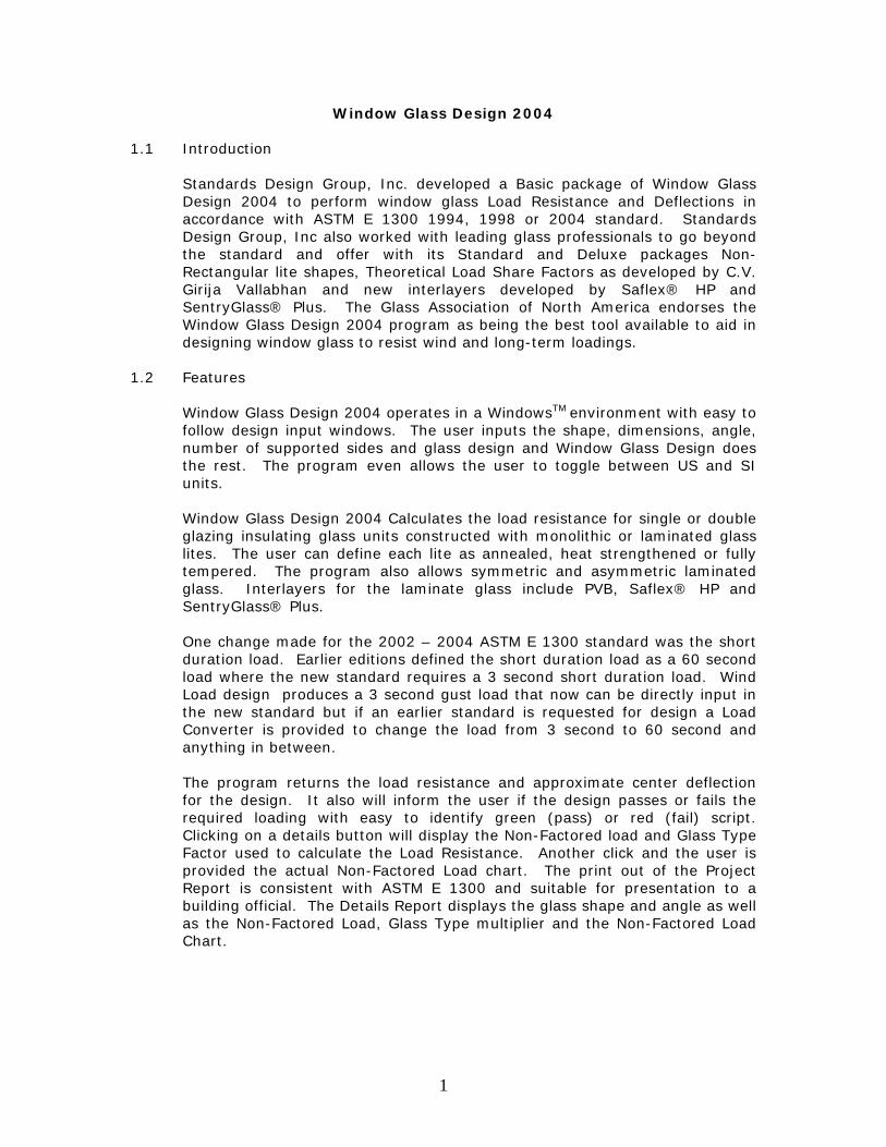
Window Glass Design 2004 1.1 Introduction
Standards Design Group, Inc. developed a Basic package of Window Glass Design 2004 to perform window glass Load Resistance and Deflections in accordance with ASTM E 1300 1994, 1998 or 2004 standard. Standards Design Group, Inc also worked with leading glass professionals to go beyond the standard and offer with its Standard and Deluxe packages Non-Rectangular lite shapes, Theoretical Load Share Factors as developed by C.V. Girija Vallabhan and new interlayers developed by Saflex® HP and SentryGlass® Plus. The Glass Association of North America endorses the Window Glass Design 2004 program as being the best tool available to aid in designing window glass to resist wind and long-term loadings.
1.2 Features
Window Glass Design 2004 operates in a WindowsTM environment with easy to follow design input windows. The user inputs the shape, dimensions, angle, number of supported sides and glass design and Window Glass Design does the rest. The program even allows the user to toggle between US and SI units. Window Glass Design 2004 Calculates the load resistance for single or double glazing insulating glass units constructed with monolithic or laminated glass lites. The user can define each lite as annealed, heat strengthened or fully tempered. The program also allows symmetric and asymmetric laminated glass. Interlayers for the laminate glass include PVB, Saflex® HP and SentryGlass® Plus. One change made for the 2002 – 2004 ASTM E 1300 standard was the short duration load. Earlier editions defined the short duration load as a 60 second load where the new standard requires a 3 second short duration load. Wind Load design produces a 3 second gust load that now can be directly input in the new standard but if an earlier standard is requested for design a Load Converter is provided to change the load from 3 second to 60 second and anything in between. The program returns the load resistance and approximate center deflection for the design. It also will inform the user if the design passes or fails the required loading with easy to identify green (pass) or red (fail) script. Clicking on a details button will display the Non-Factored load and Glass Type Factor used to calculate the Load Resistance. Another click and the user is provided the actual Non-Factored Load chart. The print out of the Project Report is consistent with ASTM E 1300 and suitable for presentation to a building official. The Details Report displays the glass shape and angle as well as the Non-Factored Load, Glass Type multiplier and the Non-Factored Load Chart.
2
Getting Started 2.1 Opening Window Glass Design 2004
Window Glass Design opens in two ways. The user can follow the path Start > All Programs > Standards Design Group, Inc > Window Glass Design 2004 or the user can navigate to a file with the extension “.gla”.
2.2 Starting a New Design
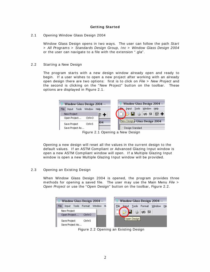
The program starts with a new design window already open and ready to begin. If a user wishes to open a new project after working with an already open design there are two options: first is to click on File > New Project and the second is clicking on the “New Project” button on the toolbar. These options are displayed in Figure 2.1.
Figure 2.1 Opening a New Design
Opening a new design will reset all the values in the current design to the default values. If an ASTM Compliant or Advanced Glazing Input window is open a new ASTM Compliant window will open. If a Multiple Glazing Input window is open a new Multiple Glazing Input window will be provided.
2.3 Opening an Existing Design
When Window Glass Design 2004 is opened, the program provides three methods for opening a saved file. The user may use the Main Menu File > Open Project or use the “Open Design” button on the toolbar, Figure 2.2.
Figure 2.2 Opening an Existing Design
3
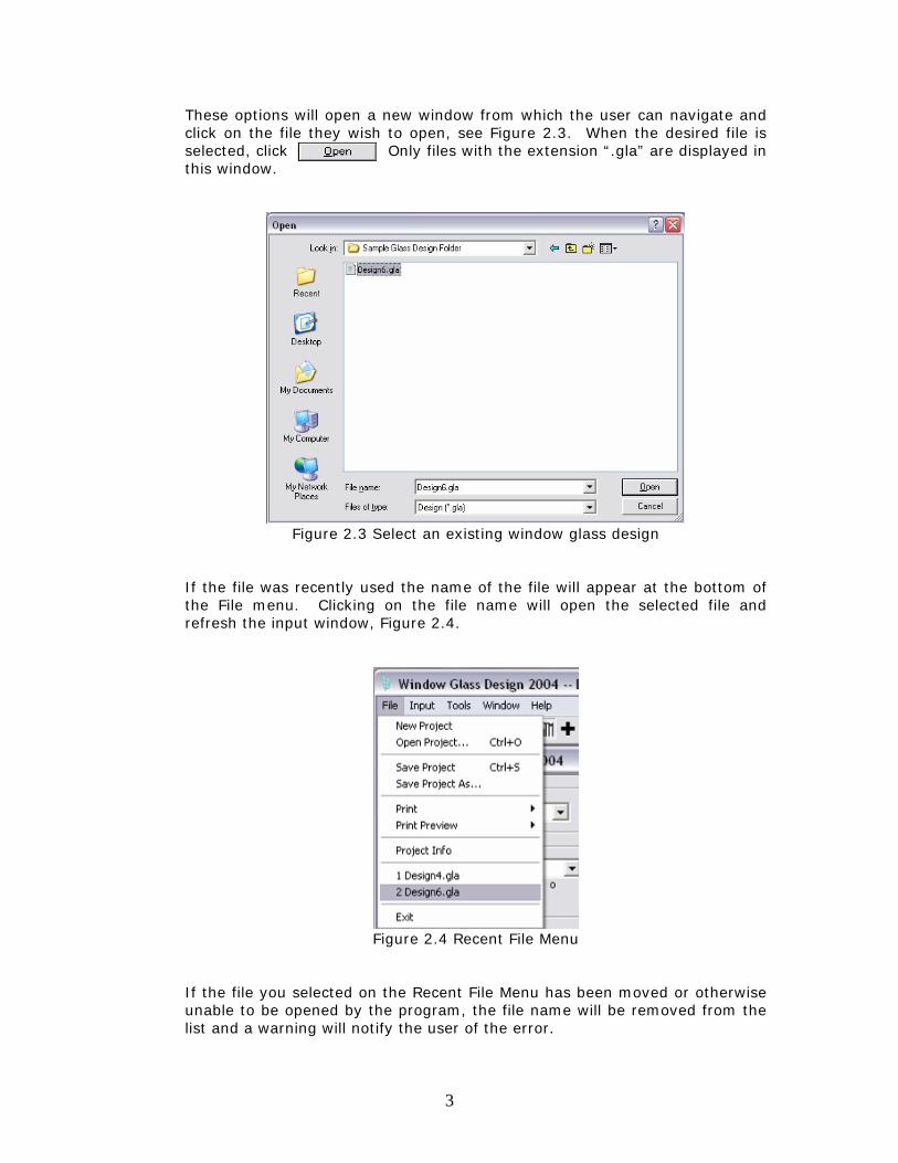
These options will open a new window from which the user can navigate and click on the file they wish to open, see Figure 2.3. When the desired file is selected, click Only files with the extension “.gla” are displayed in this window.
Figure 2.3 Select an existing window glass design
If the file was recently used the name of the file will appear at the bottom of the File menu. Clicking on the file name will open the selected file and refresh the input window, Figure 2.4.
Figure 2.4 Recent File Menu
If the file you selected on the Recent File Menu has been moved or otherwise unable to be opened by the program, the file name will be removed from the list and a warning will notify the user of the error.
4
2.4 Saving a Document
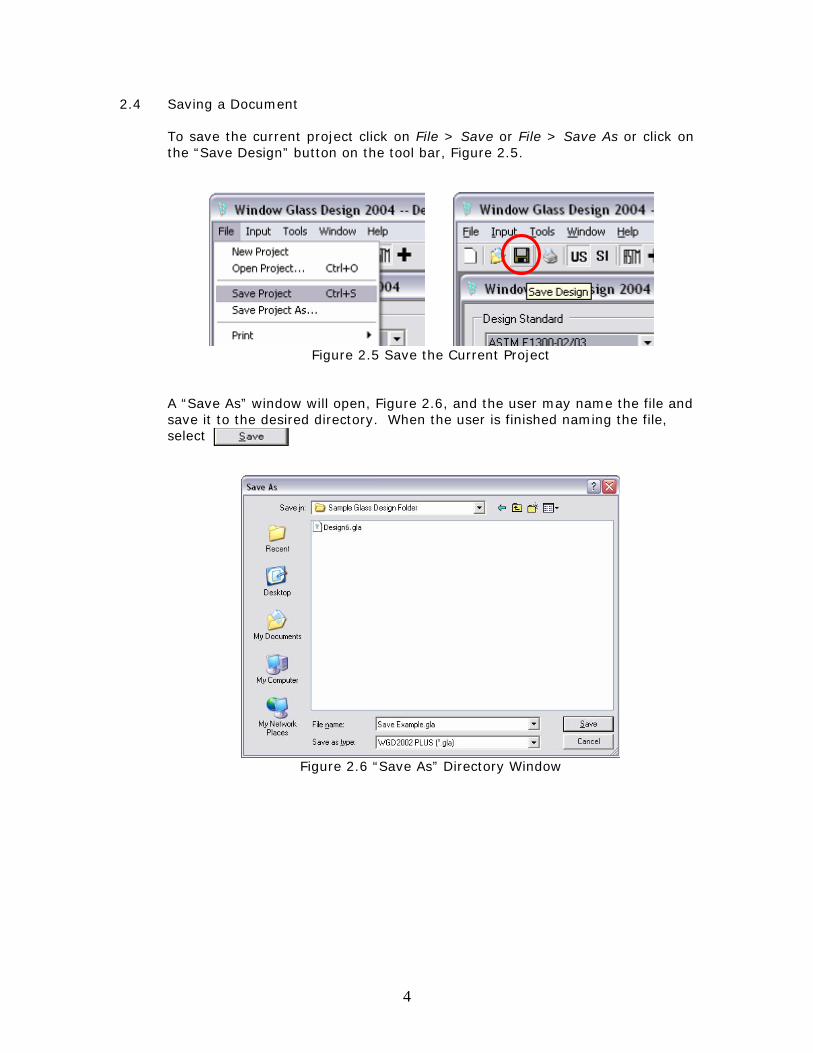
To save the current project click on File > Save or File > Save As or click on the “Save Design” button on the tool bar, Figure 2.5.
Figure 2.5 Save the Current Project
A “Save As” window will open, Figure 2.6, and the user may name the file and save it to the desired directory. When the user is finished naming the file, select
Figure 2.6 “Save As” Directory Window
5
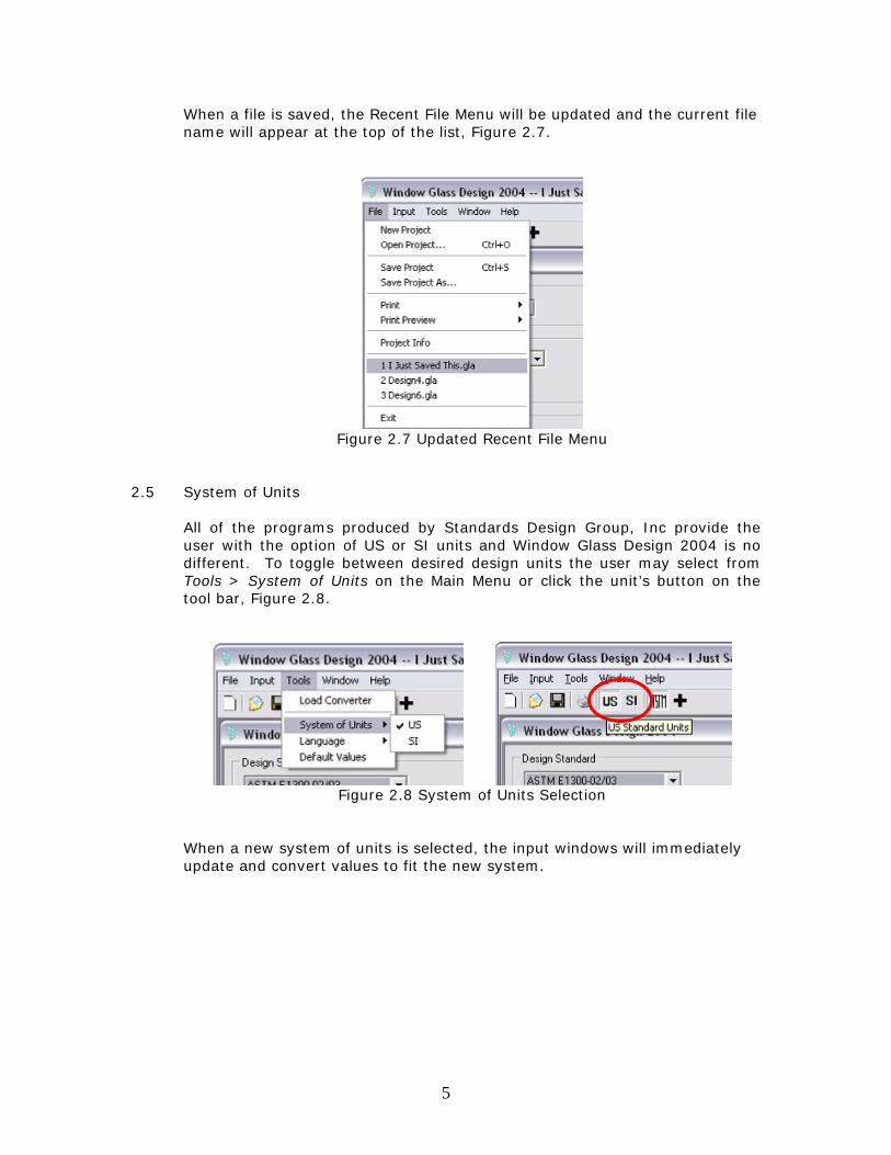
When a file is saved, the Recent File Menu will be updated and the current file name will appear at the top of the list, Figure 2.7.
Figure 2.7 Updated Recent File Menu
2.5 System of Units
All of the programs produced by Standards Design Group, Inc provide the user with the option of US or SI units and Window Glass Design 2004 is no different. To toggle between desired design units the user may select from Tools > System of Units on the Main Menu or click the unit’s button on the tool bar, Figure 2.8.
Figure 2.8 System of Units Selection
When a new system of units is selected, the input windows will immediately update and convert values to fit the new system.
6
2.6 Language
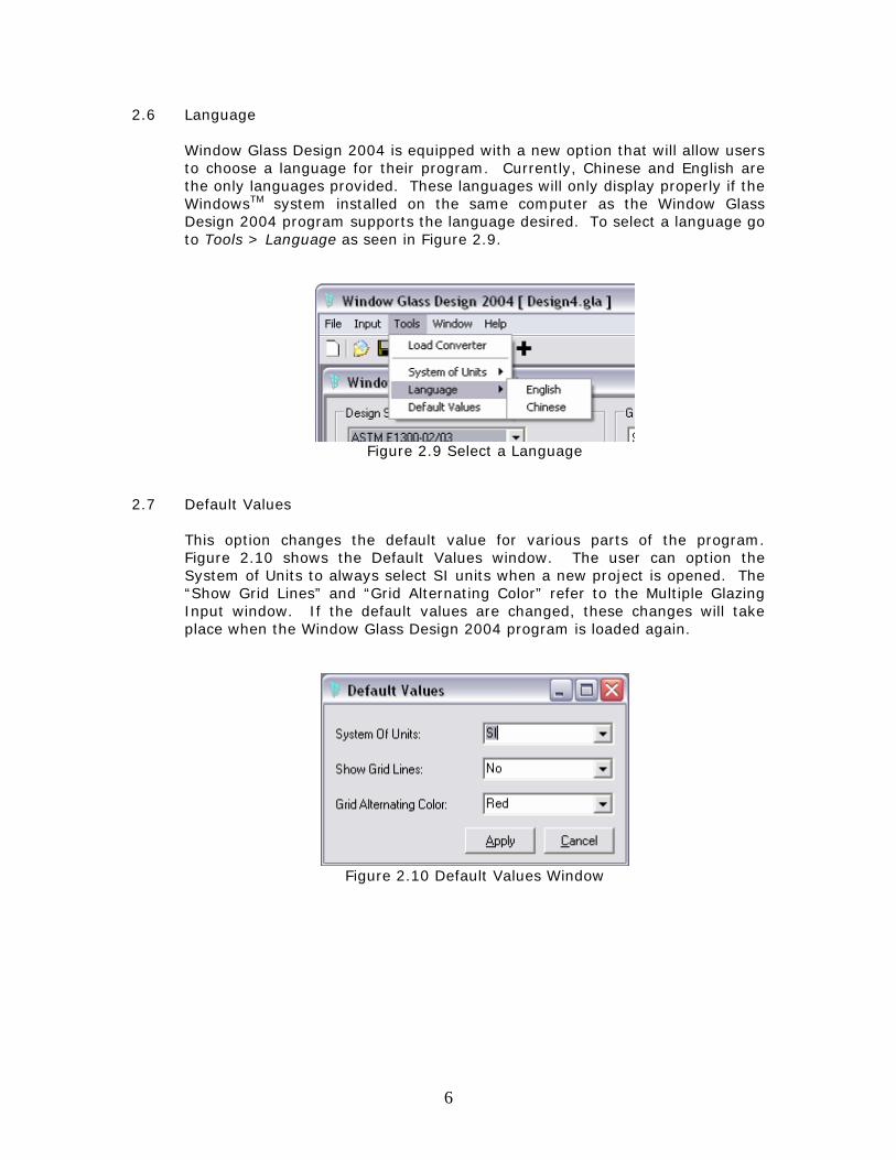
Window Glass Design 2004 is equipped with a new option that will allow users to choose a language for their program. Currently, Chinese and English are the only languages provided. These languages will only display properly if the WindowsTM system installed on the same computer as the Window Glass Design 2004 program supports the language desired. To select a language go to Tools > Language as seen in Figure 2.9.
Figure 2.9 Select a Language
2.7 Default Values
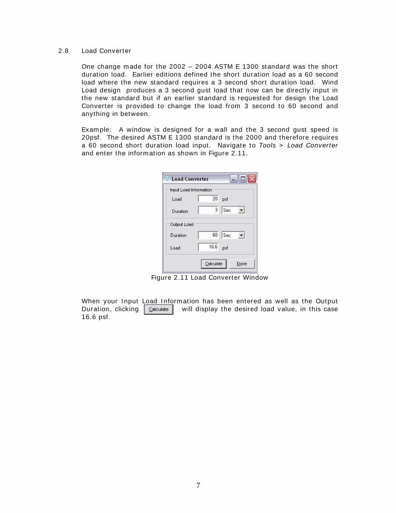
This option changes the default value for various parts of the program. Figure 2.10 shows the Default Values window. The user can option the System of Units to always select SI units when a new project is opened. The “Show Grid Lines” and “Grid Alternating Color” refer to the Multiple Glazing Input window. If the default values are changed, these changes will take place when the Window Glass Design 2004 program is loaded again.
Figure 2.10 Default Values Window
7
2.8 Load Converter
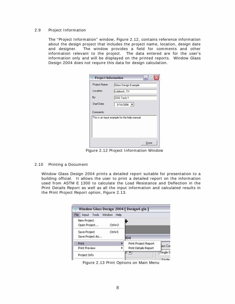
One change made for the 2002 – 2004 ASTM E 1300 standard was the short duration load. Earlier editions defined the short duration load as a 60 second load where the new standard requires a 3 second short duration load. Wind Load design produces a 3 second gust load that now can be directly input in the new standard but if an earlier standard is requested for design the Load Converter is provided to change the load from 3 second to 60 second and anything in between. Example: A window is designed for a wall and the 3 second gust speed is 20psf. The desired ASTM E 1300 standard is the 2000 and therefore requires a 60 second short duration load input. Navigate to Tools > Load Converter and enter the information as shown in Figure 2.11.
Figure 2.11 Load Converter Window
When your Input Load Information has been entered as well as the Output Duration, clicking will display the desired load value, in this case 16.6 psf.
8
2.9 Project Information
The “Project Information” window, Figure 2.12, contains reference information about the design project that includes the project name, location, design date and designer. The window provides a field for comments and other information relevant to the project. The data entered are for the user’s information only and will be displayed on the printed reports. Window Glass Design 2004 does not require this data for design calculation.
Figure 2.12 Project Information Window
2.10 Printing a Document
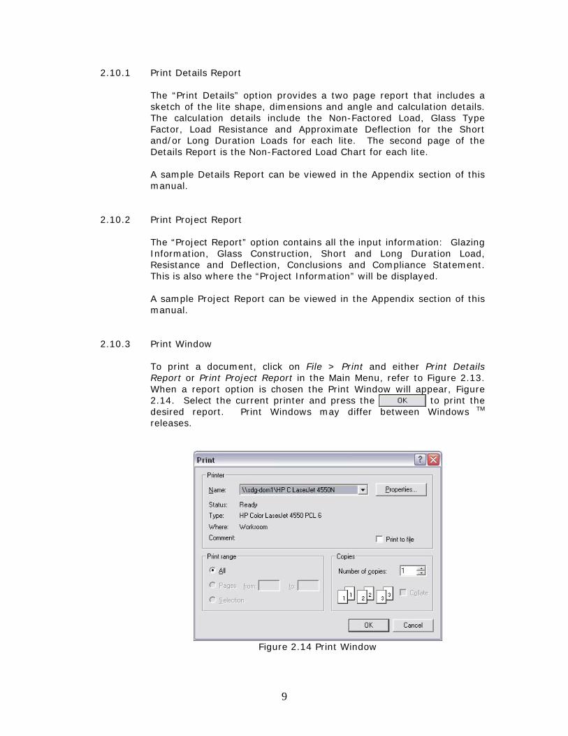
Window Glass Design 2004 prints a detailed report suitable for presentation to a building official. It allows the user to print a detailed report on the information used from ASTM E 1300 to calculate the Load Resistance and Deflection in the Print Details Report as well as all the input information and calculated results in the Print Project Report option, Figure 2.13.
Figure 2.13 Print Options on Main Menu
9
2.10.1 Print Details Report
The “Print Details” option provides a two page report that includes a sketch of the lite shape, dimensions and angle and calculation details. The calculation details include the Non-Factored Load, Glass Type Factor, Load Resistance and Approximate Deflection for the Short and/or Long Duration Loads for each lite. The second page of the Details Report is the Non-Factored Load Chart for each lite. A sample Details Report can be viewed in the Appendix section of this manual.
2.10.2 Print Project Report
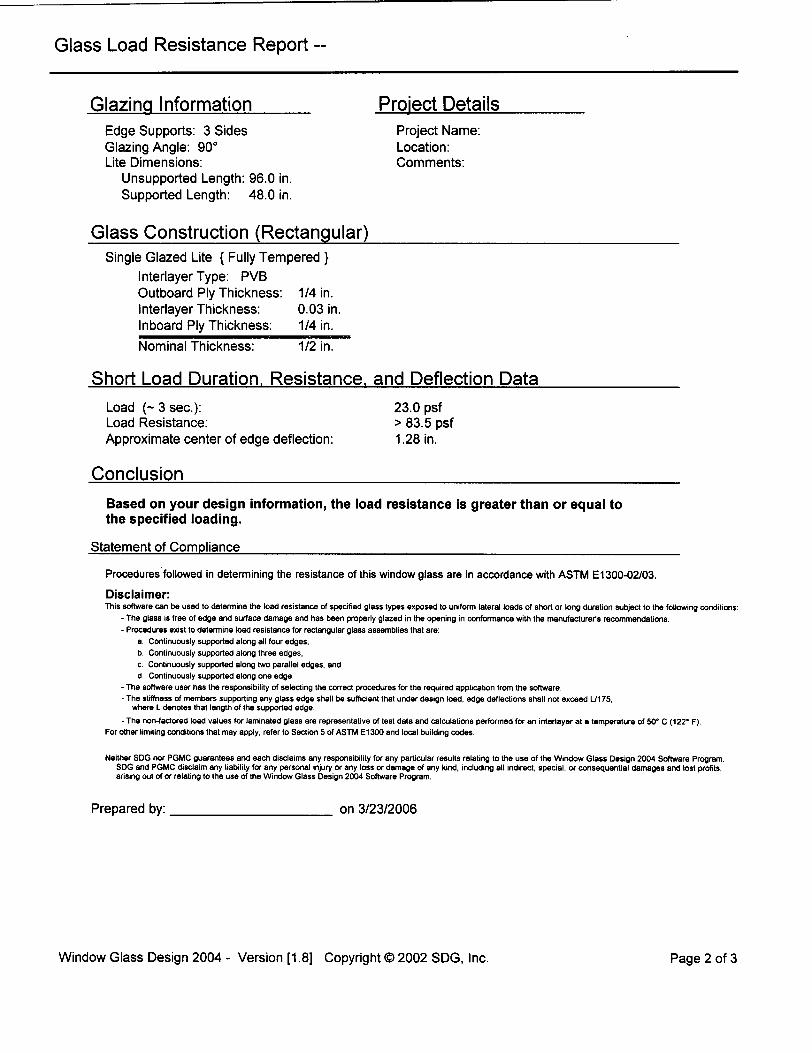
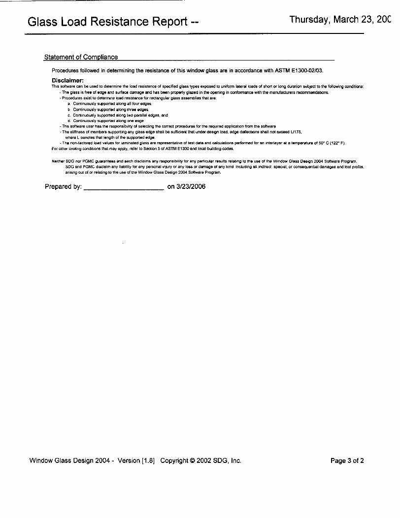
The “Project Report” option contains all the input information: Glazing Information, Glass Construction, Short and Long Duration Load, Resistance and Deflection, Conclusions and Compliance Statement. This is also where the “Project Information” will be displayed. A sample Project Report can be viewed in the Appendix section of this manual.
2.10.3 Print Window
To print a document, click on File > Print and either Print Details Report or Print Project Report in the Main Menu, refer to Figure 2.13. When a report option is chosen the Print Window will appear, Figure 2.14. Select the current printer and press the to print the desired report. Print Windows may differ between Windows TM releases.
Figure 2.14 Print Window
10
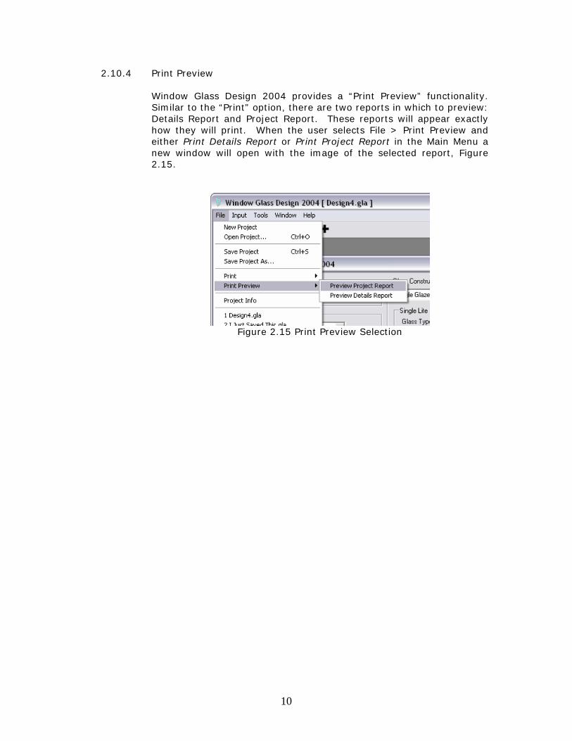
2.10.4 Print Preview Window Glass Design 2004 provides a “Print Preview” functionality. Similar to the “Print” option, there are two reports in which to preview: Details Report and Project Report. These reports will appear exactly how they will print. When the user selects File > Print Preview and either Print Details Report or Print Project Report in the Main Menu a new window will open with the image of the selected report, Figure 2.15.
Figure 2.15 Print Preview Selection
11
Input Options
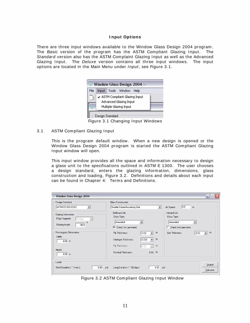
There are three input windows available to the Window Glass Design 2004 program. The Basic version of the program has the ASTM Compliant Glazing Input. The Standard version also has the ASTM Complaint Glazing Input as well as the Advanced Glazing Input. The Deluxe version contains all three input windows. The input options are located in the Main Menu under Input, see Figure 3.1.
Figure 3.1 Changing Input Windows
3.1 ASTM Compliant Glazing Input
This is the program default window. When a new design is opened or the Window Glass Design 2004 program is started the ASTM Compliant Glazing Input window will open. This input window provides all the space and information necessary to design a glass unit to the specifications outlined in ASTM E 1300. The user chooses a design standard, enters the glazing information, dimensions, glass construction and loading, Figure 3.2. Definitions and details about each input can be found in Chapter 4: Terms and Definitions.
Figure 3.2 ASTM Compliant Glazing Input Window
12
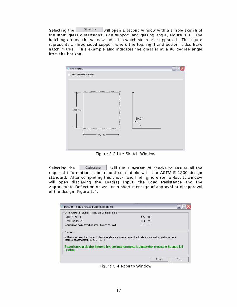
Selecting the will open a second window with a simple sketch of the input glass dimensions, side support and glazing angle, Figure 3.3. The hatching around the window indicates which sides are supported. This figure represents a three sided support where the top, right and bottom sides have hatch marks. This example also indicates the glass is at a 90 degree angle from the horizon.
Figure 3.3 Lite Sketch Window
Selecting the will run a system of checks to ensure all the required information is input and compatible with the ASTM E 1300 design standard. After completing this check, and finding no error, a Results window will open displaying the Load(s) Input, the Load Resistance and the Approximate Deflection as well as a short message of approval or disapproval of the design, Figure 3.4.
Figure 3.4 Results Window
13
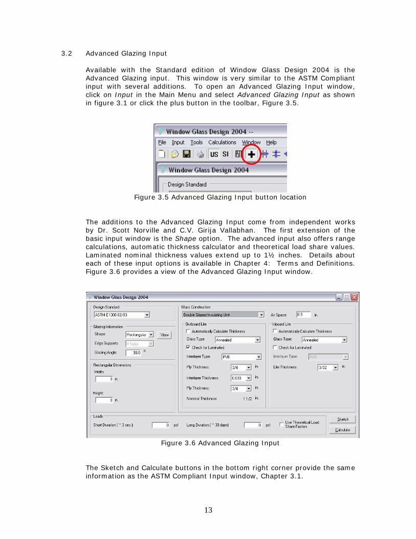
3.2 Advanced Glazing Input Available with the Standard edition of Window Glass Design 2004 is the Advanced Glazing input. This window is very similar to the ASTM Compliant input with several additions. To open an Advanced Glazing Input window, click on Input in the Main Menu and select Advanced Glazing Input as shown in figure 3.1 or click the plus button in the toolbar, Figure 3.5.
Figure 3.5 Advanced Glazing Input button location
The additions to the Advanced Glazing Input come from independent works by Dr. Scott Norville and C.V. Girija Vallabhan. The first extension of the basic input window is the Shape option. The advanced input also offers range calculations, automatic thickness calculator and theoretical load share values. Laminated nominal thickness values extend up to 1½ inches. Details about each of these input options is available in Chapter 4: Terms and Definitions. Figure 3.6 provides a view of the Advanced Glazing Input window.
Figure 3.6 Advanced Glazing Input
The Sketch and Calculate buttons in the bottom right corner provide the same information as the ASTM Compliant Input window, Chapter 3.1.
14
3.3 Multiple Glazing Input
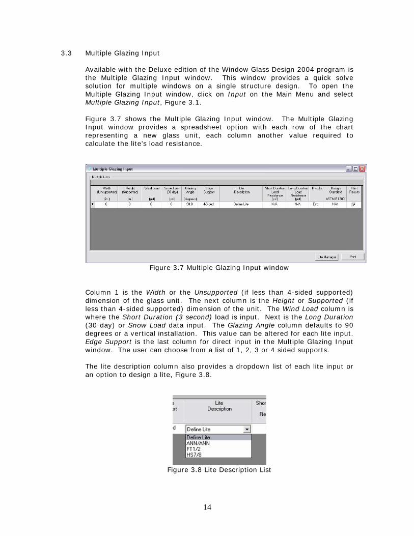
Available with the Deluxe edition of the Window Glass Design 2004 program is the Multiple Glazing Input window. This window provides a quick solve solution for multiple windows on a single structure design. To open the Multiple Glazing Input window, click on Input on the Main Menu and select Multiple Glazing Input, Figure 3.1. Figure 3.7 shows the Multiple Glazing Input window. The Multiple Glazing Input window provides a spreadsheet option with each row of the chart representing a new glass unit, each column another value required to calculate the lite’s load resistance.
Figure 3.7 Multiple Glazing Input window
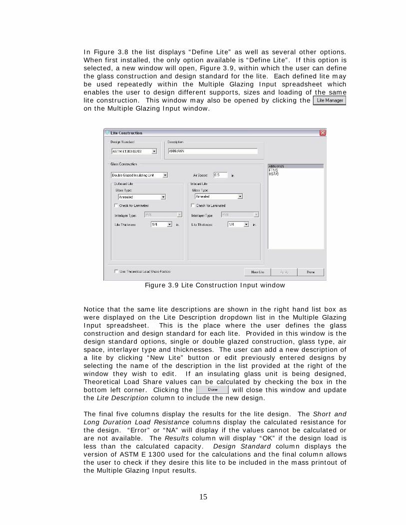
Column 1 is the Width or the Unsupported (if less than 4-sided supported) dimension of the glass unit. The next column is the Height or Supported (if less than 4-sided supported) dimension of the unit. The Wind Load column is where the Short Duration (3 second) load is input. Next is the Long Duration (30 day) or Snow Load data input. The Glazing Angle column defaults to 90 degrees or a vertical installation. This value can be altered for each lite input. Edge Support is the last column for direct input in the Multiple Glazing Input window. The user can choose from a list of 1, 2, 3 or 4 sided supports. The lite description column also provides a dropdown list of each lite input or an option to design a lite, Figure 3.8.
Figure 3.8 Lite Description List
15
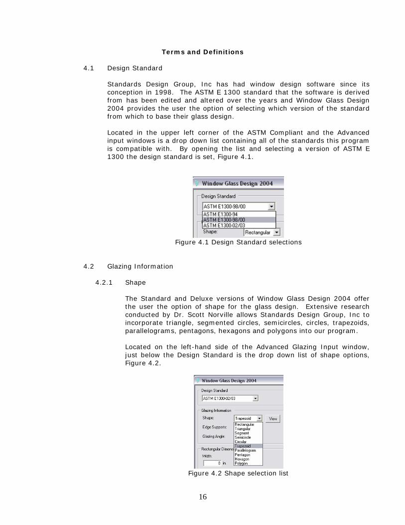
In Figure 3.8 the list displays “Define Lite” as well as several other options. When first installed, the only option available is “Define Lite”. If this option is selected, a new window will open, Figure 3.9, within which the user can define the glass construction and design standard for the lite. Each defined lite may be used repeatedly within the Multiple Glazing Input spreadsheet which enables the user to design different supports, sizes and loading of the same lite construction. This window may also be opened by clicking the . on the Multiple Glazing Input window.
Figure 3.9 Lite Construction Input window
Notice that the same lite descriptions are shown in the right hand list box as were displayed on the Lite Description dropdown list in the Multiple Glazing Input spreadsheet. This is the place where the user defines the glass construction and design standard for each lite. Provided in this window is the design standard options, single or double glazed construction, glass type, air space, interlayer type and thicknesses. The user can add a new description of a lite by clicking “New Lite” button or edit previously entered designs by selecting the name of the description in the list provided at the right of the window they wish to edit. If an insulating glass unit is being designed, Theoretical Load Share values can be calculated by checking the box in the bottom left corner. Clicking the will close this window and update the Lite Description column to include the new design. The final five columns display the results for the lite design. The Short and Long Duration Load Resistance columns display the calculated resistance for the design. “Error” or “NA” will display if the values cannot be calculated or are not available. The Results column will display “OK” if the design load is less than the calculated capacity. Design Standard column displays the version of ASTM E 1300 used for the calculations and the final column allows the user to check if they desire this lite to be included in the mass printout of the Multiple Glazing Input results.
16
Terms and Definitions
4.1 Design Standard
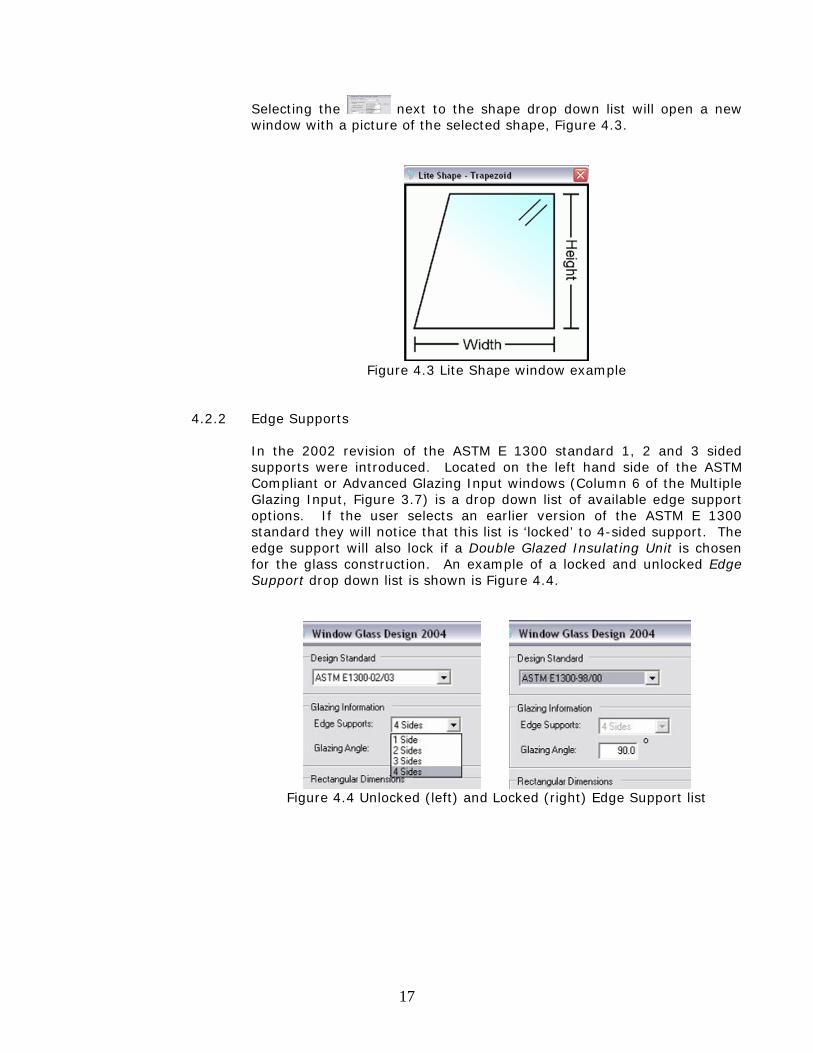
Standards Design Group, Inc has had window design software since its conception in 1998. The ASTM E 1300 standard that the software is derived from has been edited and altered over the years and Window Glass Design 2004 provides the user the option of selecting which version of the standard from which to base their glass design. Located in the upper left corner of the ASTM Compliant and the Advanced input windows is a drop down list containing all of the standards this program is compatible with. By opening the list and selecting a version of ASTM E 1300 the design standard is set, Figure 4.1.
Figure 4.1 Design Standard selections
4.2 Glazing Information
4.2.1 Shape
The Standard and Deluxe versions of Window Glass Design 2004 offer the user the option of shape for the glass design. Extensive research conducted by Dr. Scott Norville allows Standards Design Group, Inc to incorporate triangle, segmented circles, semicircles, circles, trapezoids, parallelograms, pentagons, hexagons and polygons into our program. Located on the left-hand side of the Advanced Glazing Input window, just below the Design Standard is the drop down list of shape options, Figure 4.2.
Figure 4.2 Shape selection list
17
Selecting the next to the shape drop down list will open a new window with a picture of the selected shape, Figure 4.3.
Figure 4.3 Lite Shape window example
4.2.2 Edge Supports
In the 2002 revision of the ASTM E 1300 standard 1, 2 and 3 sided supports were introduced. Located on the left hand side of the ASTM Compliant or Advanced Glazing Input windows (Column 6 of the Multiple Glazing Input, Figure 3.7) is a drop down list of available edge support options. If the user selects an earlier version of the ASTM E 1300 standard they will notice that this list is ‘locked’ to 4-sided support. The edge support will also lock if a Double Glazed Insulating Unit is chosen for the glass construction. An example of a locked and unlocked Edge Support drop down list is shown is Figure 4.4.
Figure 4.4 Unlocked (left) and Locked (right) Edge Support list
18
4.2.3 Glazing Angle
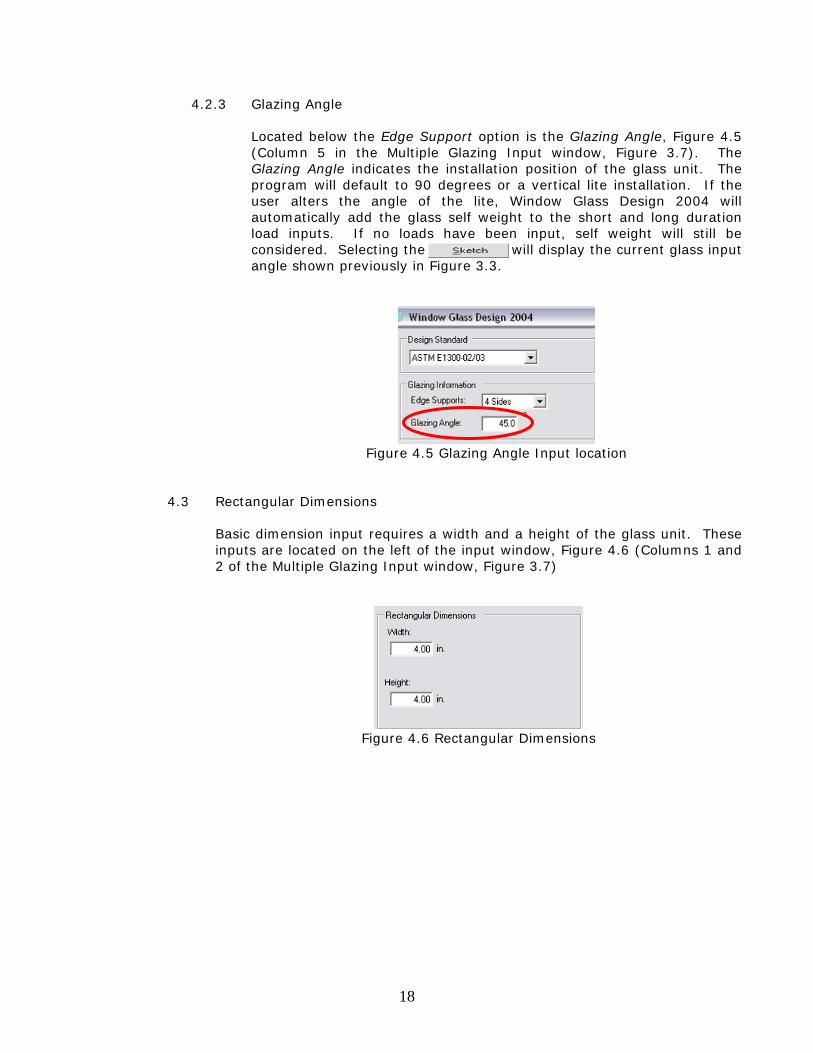
Located below the Edge Support option is the Glazing Angle, Figure 4.5 (Column 5 in the Multiple Glazing Input window, Figure 3.7). The Glazing Angle indicates the installation position of the glass unit. The program will default to 90 degrees or a vertical lite installation. If the user alters the angle of the lite, Window Glass Design 2004 will automatically add the glass self weight to the short and long duration load inputs. If no loads have been input, self weight will still be considered. Selecting the will display the current glass input angle shown previously in Figure 3.3.
Figure 4.5 Glazing Angle Input location
4.3 Rectangular Dimensions
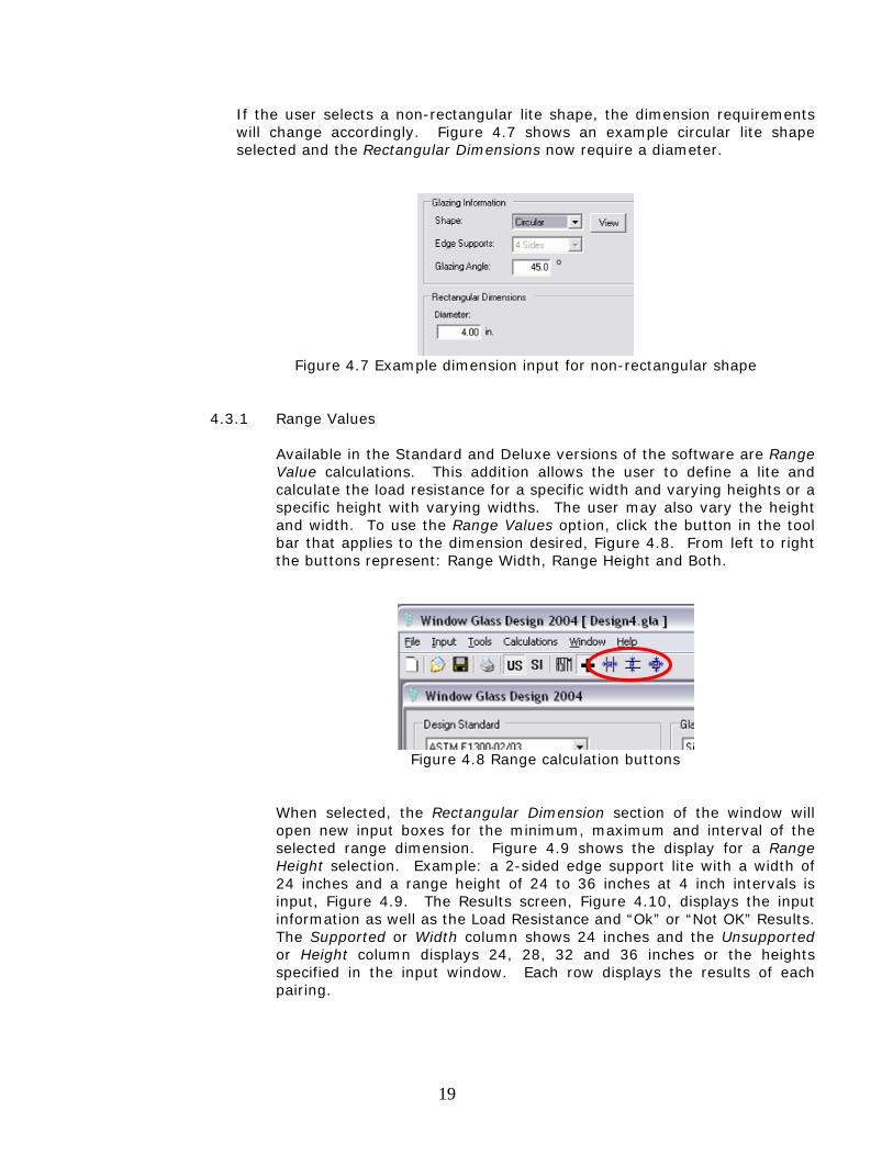
Basic dimension input requires a width and a height of the glass unit. These inputs are located on the left of the input window, Figure 4.6 (Columns 1 and 2 of the Multiple Glazing Input window, Figure 3.7)
Figure 4.6 Rectangular Dimensions
19
If the user selects a non-rectangular lite shape, the dimension requirements will change accordingly. Figure 4.7 shows an example circular lite shape selected and the Rectangular Dimensions now require a diameter.
Figure 4.7 Example dimension input for non-rectangular shape
4.3.1 Range Values
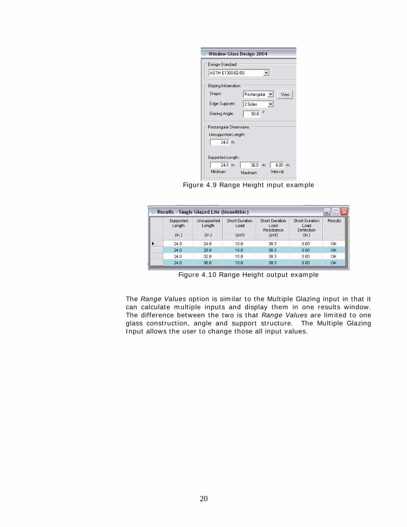
Available in the Standard and Deluxe versions of the software are Range Value calculations. This addition allows the user to define a lite and calculate the load resistance for a specific width and varying heights or a specific height with varying widths. The user may also vary the height and width. To use the Range Values option, click the button in the tool bar that applies to the dimension desired, Figure 4.8. From left to right the buttons represent: Range Width, Range Height and Both.
Figure 4.8 Range calculation buttons
When selected, the Rectangular Dimension section of the window will open new input boxes for the minimum, maximum and interval of the selected range dimension. Figure 4.9 shows the display for a Range Height selection. Example: a 2-sided edge support lite with a width of 24 inches and a range height of 24 to 36 inches at 4 inch intervals is input, Figure 4.9. The Results screen, Figure 4.10, displays the input information as well as the Load Resistance and “Ok” or “Not OK” Results. The Supported or Width column shows 24 inches and the Unsupported or Height column displays 24, 28, 32 and 36 inches or the heights specified in the input window. Each row displays the results of each pairing.
20
Figure 4.9 Range Height input example
Figure 4.10 Range Height output example
The Range Values option is similar to the Multiple Glazing input in that it can calculate multiple inputs and display them in one results window. The difference between the two is that Range Values are limited to one glass construction, angle and support structure. The Multiple Glazing Input allows the user to change those all input values.
21
4.4 Glass Construction
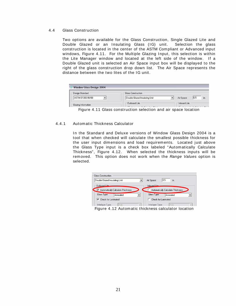
Two options are available for the Glass Construction, Single Glazed Lite and Double Glazed or an Insulating Glass (IG) unit. Selection the glass construction is located in the center of the ASTM Compliant or Advanced input windows, Figure 4.11. For the Multiple Glazing Input, this selection is within the Lite Manager window and located at the left side of the window. If a Double Glazed unit is selected an Air Space input box will be displayed to the right of the glass construction drop down list. The Air Space represents the distance between the two lites of the IG unit.
Figure 4.11 Glass construction selection and air space location
4.4.1 Automatic Thickness Calculator
In the Standard and Deluxe versions of Window Glass Design 2004 is a tool that when checked will calculate the smallest possible thickness for the user input dimensions and load requirements. Located just above the Glass Type input is a check box labeled “Automatically Calculate Thickness”, Figure 4.12. When selected the thickness inputs will be removed. This option does not work when the Range Values option is selected.
Figure 4.12 Automatic thickness calculator location
22
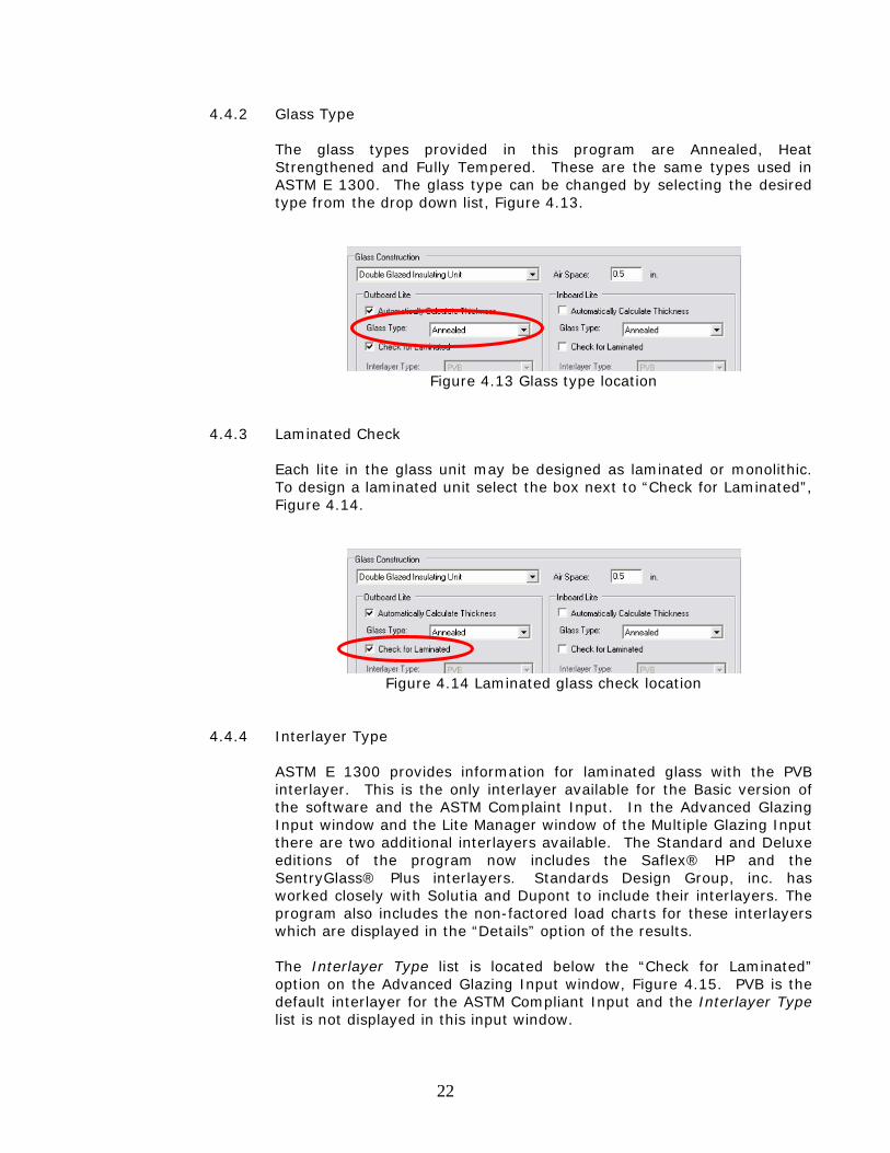
4.4.2 Glass Type
The glass types provided in this program are Annealed, Heat Strengthened and Fully Tempered. These are the same types used in ASTM E 1300. The glass type can be changed by selecting the desired type from the drop down list, Figure 4.13.
Figure 4.13 Glass type location
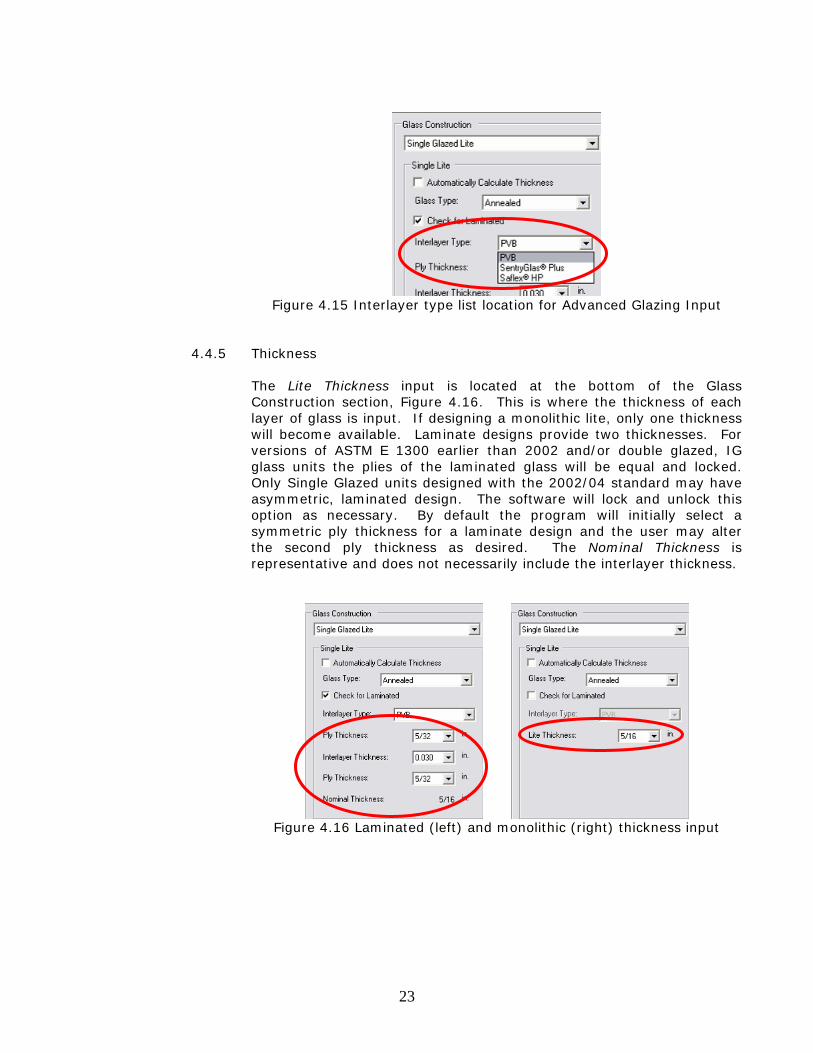
4.4.3 Laminated Check
Each lite in the glass unit may be designed as laminated or monolithic. To design a laminated unit select the box next to “Check for Laminated”, Figure 4.14.
Figure 4.14 Laminated glass check location
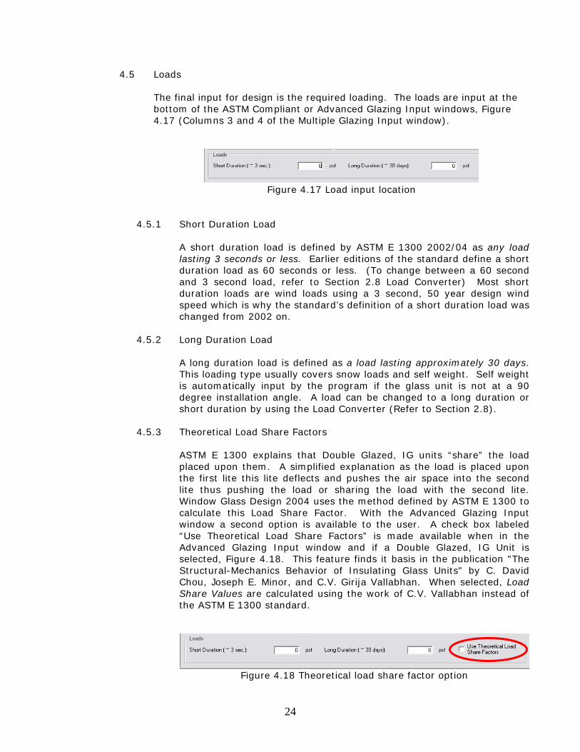
4.4.4 Interlayer Type
ASTM E 1300 provides information for laminated glass with the PVB interlayer. This is the only interlayer available for the Basic version of the software and the ASTM Complaint Input. In the Advanced Glazing Input window and the Lite Manager window of the Multiple Glazing Input there are two additional interlayers available. The Standard and Deluxe editions of the program now includes the Saflex® HP and the SentryGlass® Plus interlayers. Standards Design Group, inc. has worked closely with Solutia and Dupont to include their interlayers. The program also includes the non-factored load charts for these interlayers which are displayed in the “Details” option of the results. The Interlayer Type list is located below the “Check for Laminated” option on the Advanced Glazing Input window, Figure 4.15. PVB is the default interlayer for the ASTM Compliant Input and the Interlayer Type list is not displayed in this input window.
23
Figure 4.15 Interlayer type list location for Advanced Glazing Input
4.4.5 Thickness
The Lite Thickness input is located at the bottom of the Glass Construction section, Figure 4.16. This is where the thickness of each layer of glass is input. If designing a monolithic lite, only one thickness will become available. Laminate designs provide two thicknesses. For versions of ASTM E 1300 earlier than 2002 and/or double glazed, IG glass units the plies of the laminated glass will be equal and locked. Only Single Glazed units designed with the 2002/04 standard may have asymmetric, laminated design. The software will lock and unlock this option as necessary. By default the program will initially select a symmetric ply thickness for a laminate design and the user may alter the second ply thickness as desired. The Nominal Thickness is representative and does not necessarily include the interlayer thickness.
Figure 4.16 Laminated (left) and monolithic (right) thickness input
24
4.5 Loads
The final input for design is the required loading. The loads are input at the bottom of the ASTM Compliant or Advanced Glazing Input windows, Figure 4.17 (Columns 3 and 4 of the Multiple Glazing Input window).
Figure 4.17 Load input location
4.5.1 Short Duration Load
A short duration load is defined by ASTM E 1300 2002/04 as any load lasting 3 seconds or less. Earlier editions of the standard define a short duration load as 60 seconds or less. (To change between a 60 second and 3 second load, refer to Section 2.8 Load Converter) Most short duration loads are wind loads using a 3 second, 50 year design wind speed which is why the standard’s definition of a short duration load was changed from 2002 on.
4.5.2 Long Duration Load
A long duration load is defined as a load lasting approximately 30 days. This loading type usually covers snow loads and self weight. Self weight is automatically input by the program if the glass unit is not at a 90 degree installation angle. A load can be changed to a long duration or short duration by using the Load Converter (Refer to Section 2.8).
4.5.3 Theoretical Load Share Factors
ASTM E 1300 explains that Double Glazed, IG units “share” the load placed upon them. A simplified explanation as the load is placed upon the first lite this lite deflects and pushes the air space into the second lite thus pushing the load or sharing the load with the second lite. Window Glass Design 2004 uses the method defined by ASTM E 1300 to calculate this Load Share Factor. With the Advanced Glazing Input window a second option is available to the user. A check box labeled “Use Theoretical Load Share Factors” is made available when in the Advanced Glazing Input window and if a Double Glazed, IG Unit is selected, Figure 4.18. This feature finds it basis in the publication "The Structural-Mechanics Behavior of Insulating Glass Units" by C. David Chou, Joseph E. Minor, and C.V. Girija Vallabhan. When selected, Load Share Values are calculated using the work of C.V. Vallabhan instead of the ASTM E 1300 standard.
Figure 4.18 Theoretical load share factor option
25
Results
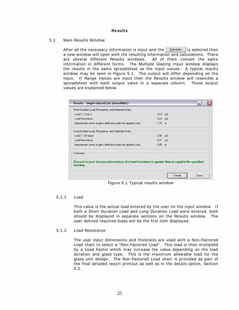
5.1 Main Results Window
After all the necessary information is input and the is selected then a new window will open with the resulting information and calculations. There are several different Results windows. All of them contain the same information in different forms. The Multiple Glazing Input window displays the results in the same spreadsheet as the input values. A typical results window may be seen in Figure 5.1. The output will differ depending on the input. If Range Values are input then the Results window will resemble a spreadsheet with each output value in a separate column. These output values are explained below.
Figure 5.1 Typical results window
5.1.1 Load
This value is the actual load entered by the user on the input window. If both a Short Duration Load and Long Duration Load were entered, both should be displayed in separate sections on the Results window. The user defined required loads will be the first item displayed.
5.1.2 Load Resistance
The user input dimensions and thickness are used with a Non-Factored Load chart to select a “Non-Factored Load”. This load is then multiplied by a Load Factor which may increase the value depending on the load duration and glass type. This is the maximum allowable load for the glass unit design. The Non-Factored Load chart is provided as part of the final detailed report printout as well as in the details option, Section 5.2.
26
5.1.3 Approximate Deflection
A second chart is used that allows the user to locate the approximate deflection. This chart requires the user input load and dimension information. The Approximate Deflection is in the center for 4-sided and 2-sided supports and on the edge of glass for 3-sided and 1-sided supports.
5.1.4 Comments
The final section of the Results window are the comments. In the Multiple Glazing Input and Range Value results windows these comments are an “OK” or “Not OK” as a pass/fail display of the required load on the input glass design. On the basic Results window these comments include a green display for “pass” and red display for “fail” of the unit design. If the load required of the glass design exceeds the calculated factored load then the lite is unacceptable according to ASTM E 1300. Probability of Breakage: A numerical “safety factor” is not provided for glass design. Instead a “Probability of Breakage” is given. This is the possibility of how many units out of 1000 with this design and load condition will break.
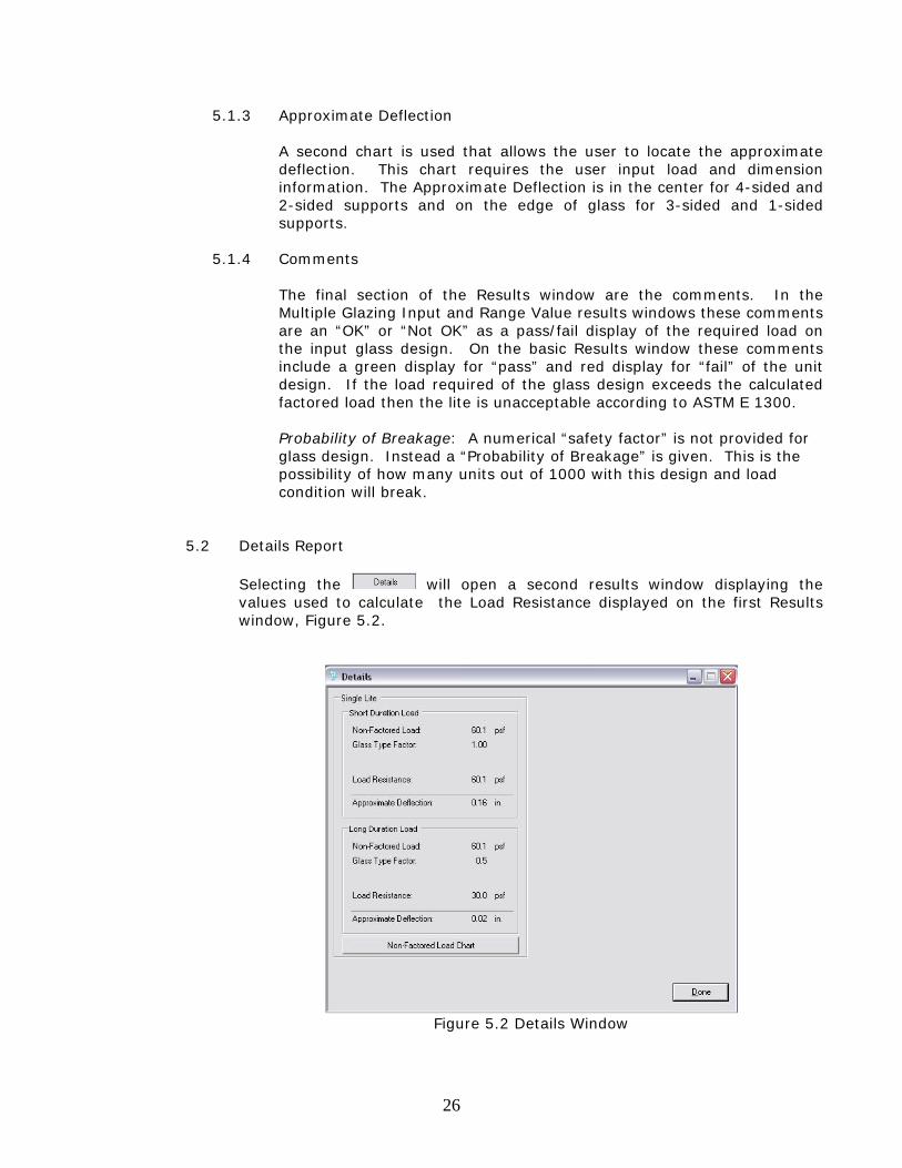
5.2 Details Report
Selecting the will open a second results window displaying the values used to calculate the Load Resistance displayed on the first Results window, Figure 5.2.
Figure 5.2 Details Window
27
5.2.1 Non-Factored Load
The Non-Factored Load is found using charts provided by ASTM E 1300. The charts require dimension and thickness information and using this information a Non-Factored load is found. The first value in the Details Window is the load from the chart.
5.2.2 Glass Type Factor
The second value displayed on the Details window is the Glass Type Factor. This factor, provided in Tables 1 and 2 of the ASTM E 1300 standard, are multipliers for the Non Factored Load. The Glass Type Factor is selected based on the load duration, glass construction and glass type. A long duration, IG unit constructed of monolithic fully tempered glass has a Glass Type Factor of 2.85 for both lites where as a short duration load, single glazed, annealed glass unit has a Glass Type Factor of 1.
5.2.3 Load Resistance
Multiplying the Glass Type Factor with the Non-Factored load will produce the Load Resistance of the glass unit. The Load Resistance is the third line displayed in the Details Window and is also shown in the Results window.
5.2.4 Approximate Deflection
This value is the same as displayed in the Results window, Section 5.1.3.
28
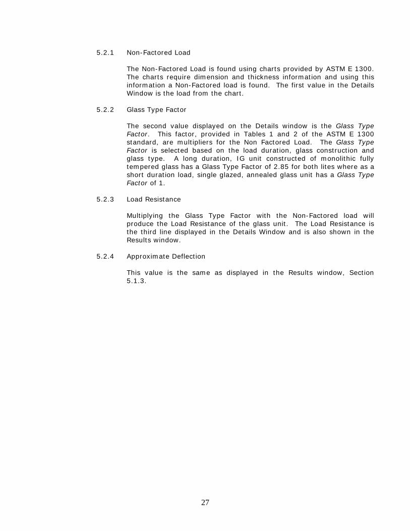
5.3 Non-Factored Load Chart
Selecting the will open a third results window. The Non-Factored Load chart is taken from the ASTM E 1300 standard and is what is used to find the Non-Factored Load, Figure 5.3. Red lines mark the dimensions used to locate the Non-Factored Load. Interpolation is used when the lines cross between two loads.
Figure 5.3 Non-Factored load chart
This chart may be printed by selecting from the Main Menu File > Print > Print Details Report.
A1 - 1
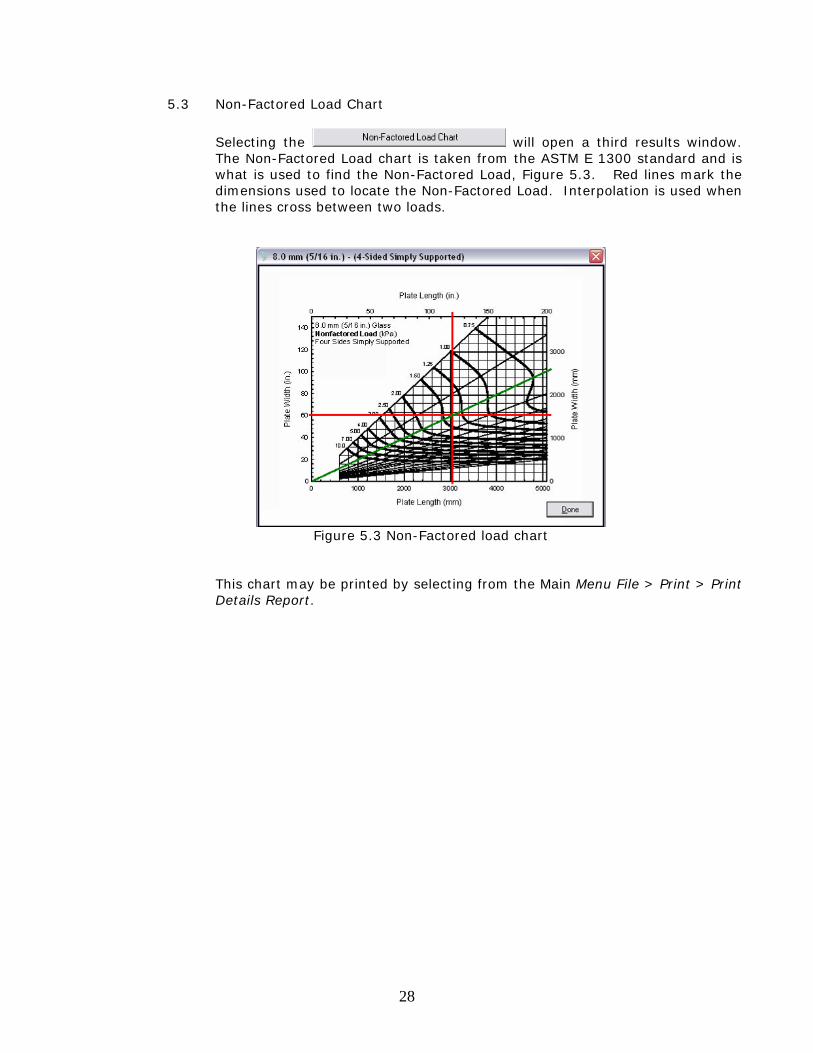
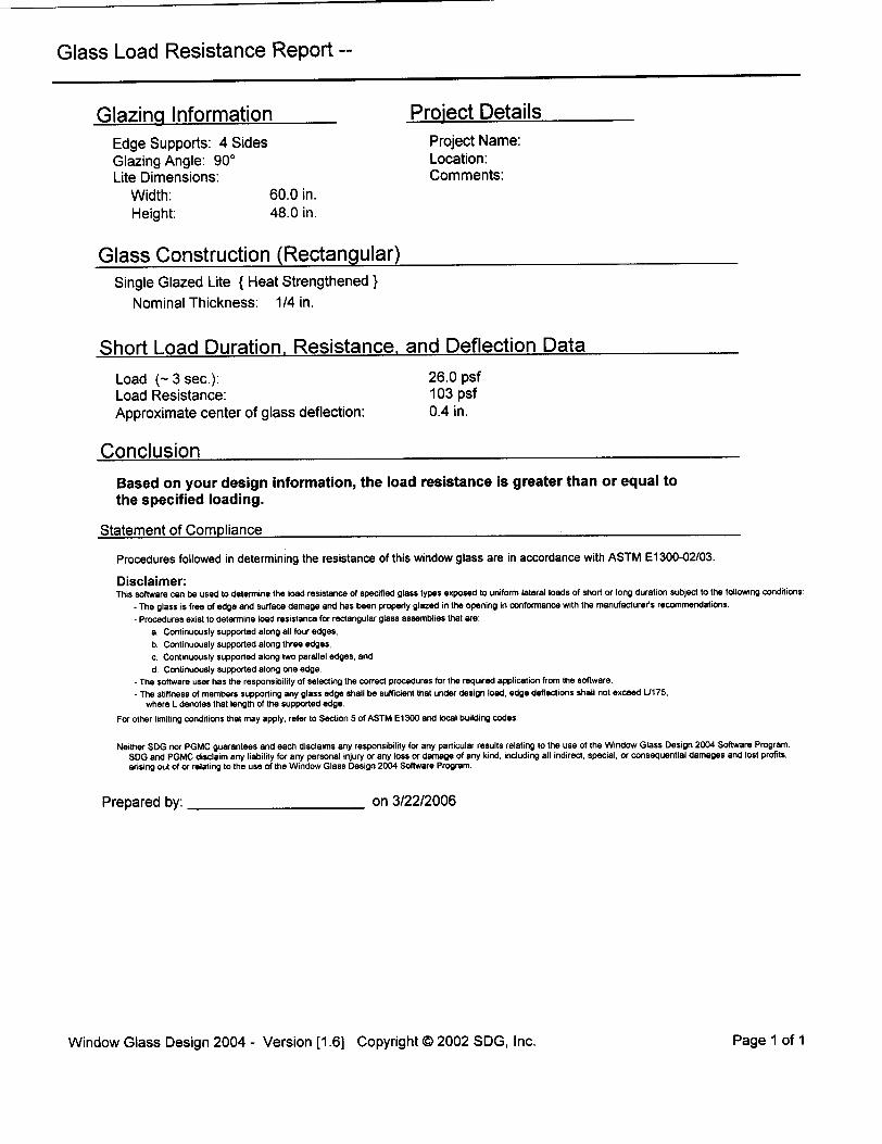
Appendix A: ASTM Compliant Glazing Design Example Glass Input Dimension: 60 inch x 48 inch, ¼ inch thickness Glass Type: Single Glazed, Heat Strengthened, 4-sided support Load Requirement: Wind Load of 26 psf Design Standard: ASTM E 1300 - 2004 Input The default design standard is “ASTM E 1300-2002/03” (Note: no calculation changes have occurred between the 2002 and 2004) The default edge support is 4-sided. The default glazing angle is 90 degrees.
In the Width box, enter 60 In the Height box, enter 48
In the Glass Construction Single Glazed Lite is a default Select Glass Type “Heat Strengthened”
A1 - 2
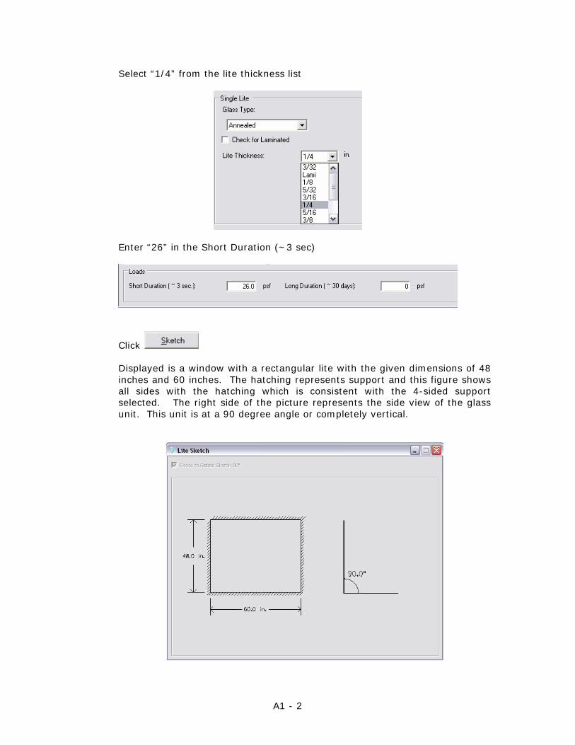
Select “1/4” from the lite thickness list
Enter “26” in the Short Duration (~3 sec)
Click
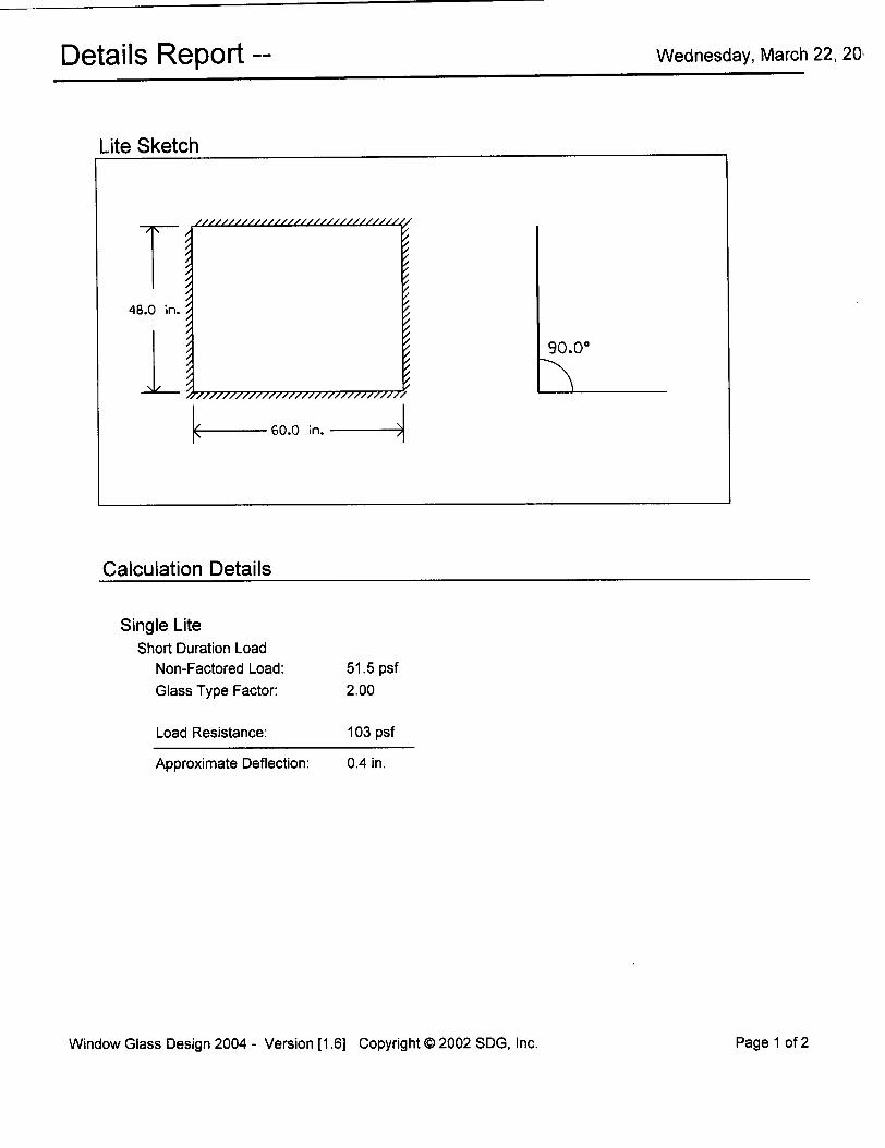
Displayed is a window with a rectangular lite with the given dimensions of 48 inches and 60 inches. The hatching represents support and this figure shows all sides with the hatching which is consistent with the 4-sided support selected. The right side of the picture represents the side view of the glass unit. This unit is at a 90 degree angle or completely vertical.
A1 - 3
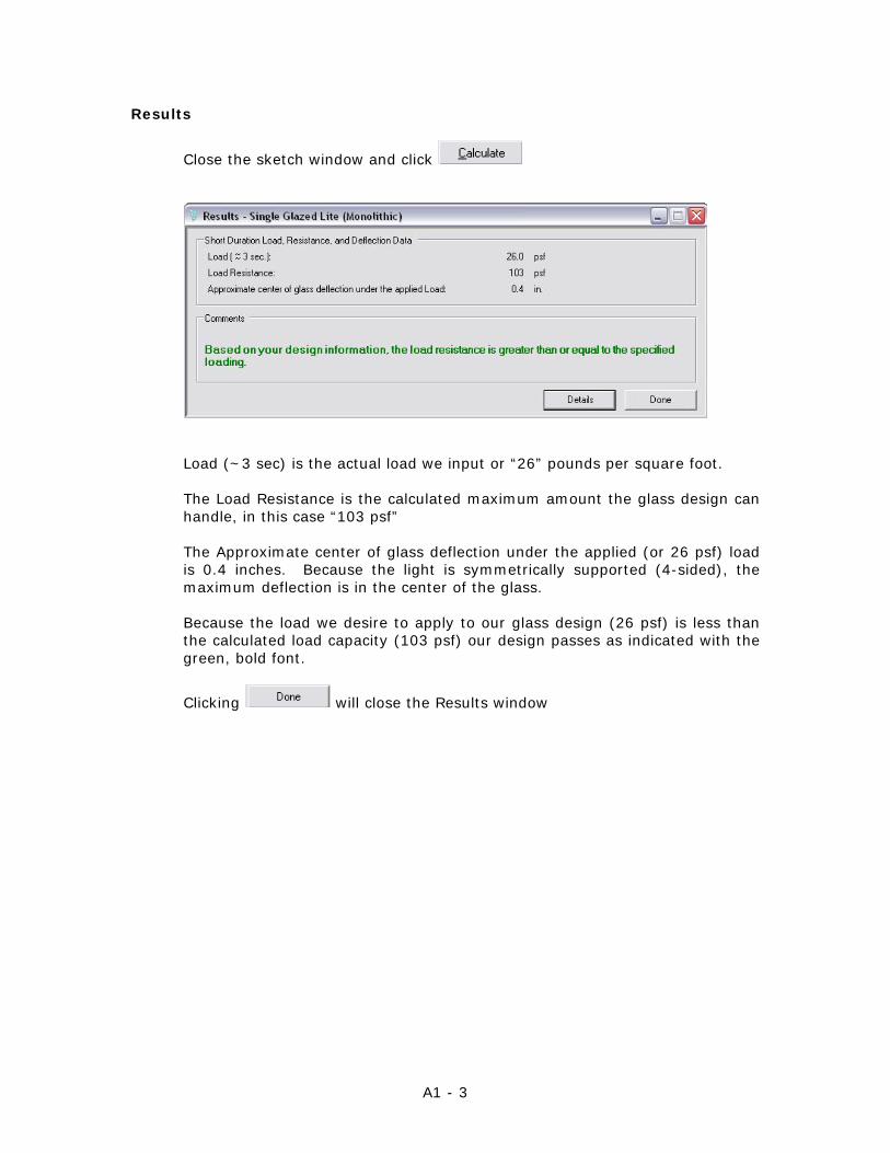
Results
Close the sketch window and click
Load (~3 sec) is the actual load we input or “26” pounds per square foot.
The Load Resistance is the calculated maximum amount the glass design can handle, in this case “103 psf” The Approximate center of glass deflection under the applied (or 26 psf) load is 0.4 inches. Because the light is symmetrically supported (4-sided), the maximum deflection is in the center of the glass. Because the load we desire to apply to our glass design (26 psf) is less than the calculated load capacity (103 psf) our design passes as indicated with the green, bold font.
Clicking will close the Results window
A1 - 4
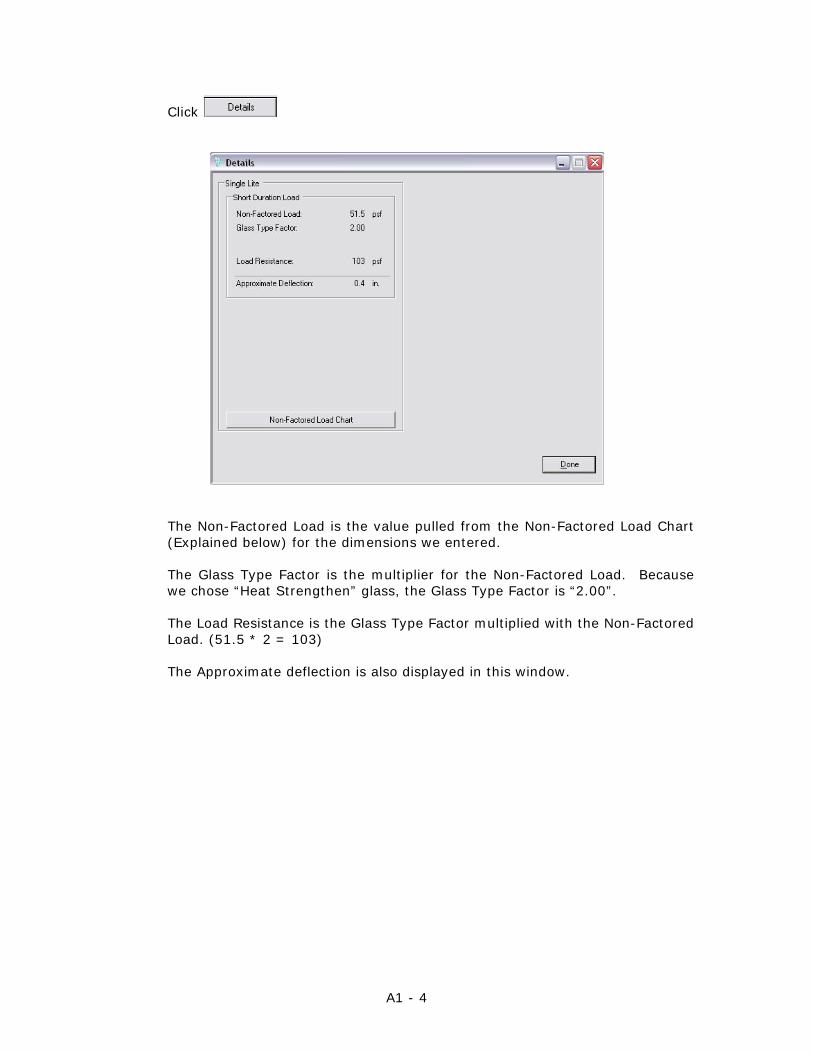
Click
The Non-Factored Load is the value pulled from the Non-Factored Load Chart (Explained below) for the dimensions we entered. The Glass Type Factor is the multiplier for the Non-Factored Load. Because we chose “Heat Strengthen” glass, the Glass Type Factor is “2.00”. The Load Resistance is the Glass Type Factor multiplied with the Non-Factored Load. (51.5 * 2 = 103) The Approximate deflection is also displayed in this window.
A1 - 5
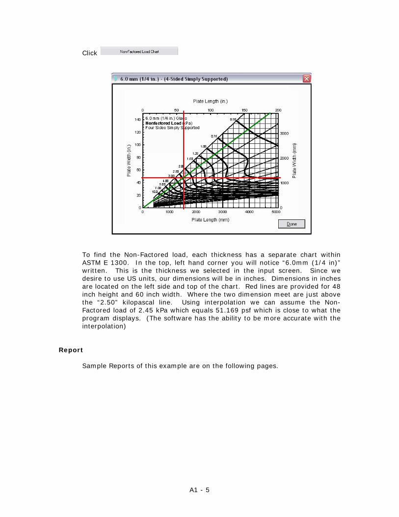
Click
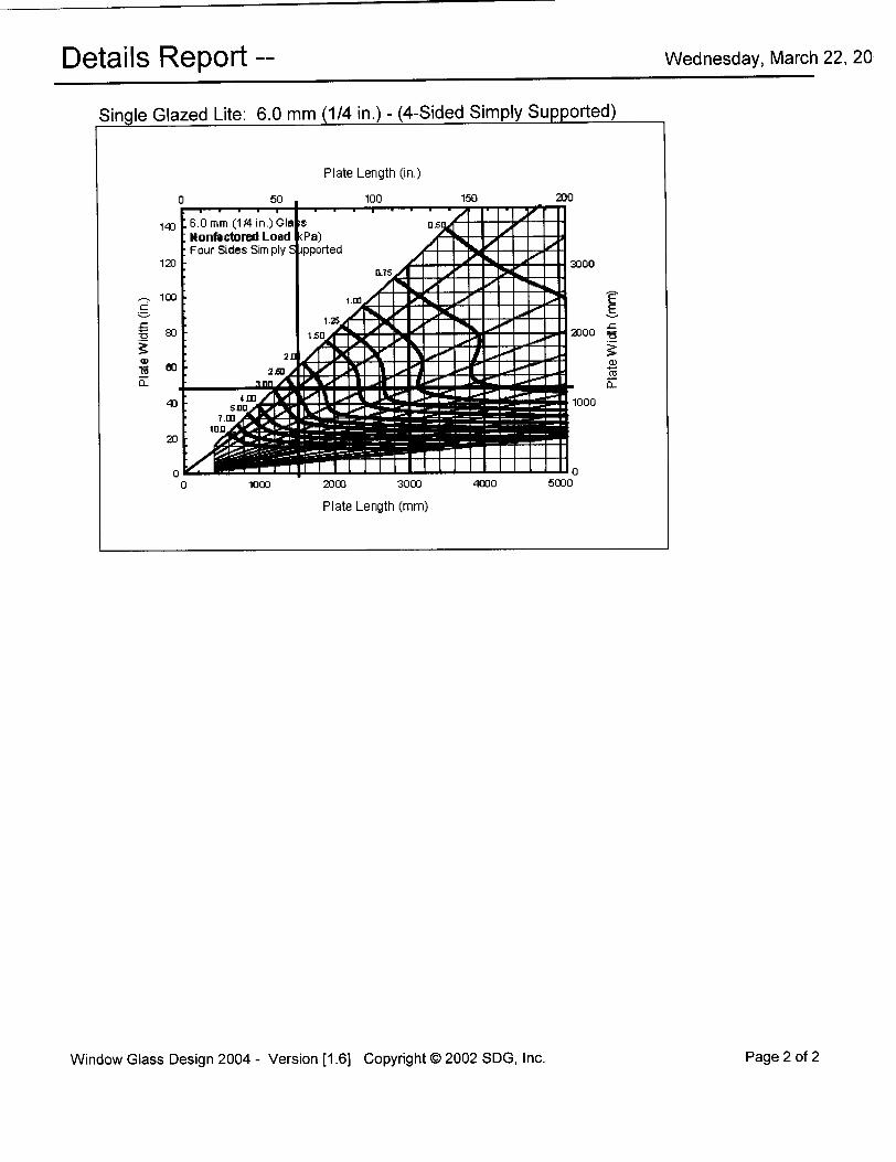
To find the Non-Factored load, each thickness has a separate chart within ASTM E 1300. In the top, left hand corner you will notice “6.0mm (1/4 in)” written. This is the thickness we selected in the input screen. Since we desire to use US units, our dimensions will be in inches. Dimensions in inches are located on the left side and top of the chart. Red lines are provided for 48 inch height and 60 inch width. Where the two dimension meet are just above the “2.50” kilopascal line. Using interpolation we can assume the Non-Factored load of 2.45 kPa which equals 51.169 psf which is close to what the program displays. (The software has the ability to be more accurate with the interpolation)
Report
Sample Reports of this example are on the following pages.
A2 - 1
Appendix A: Advanced Glazing Design Example Glass Input
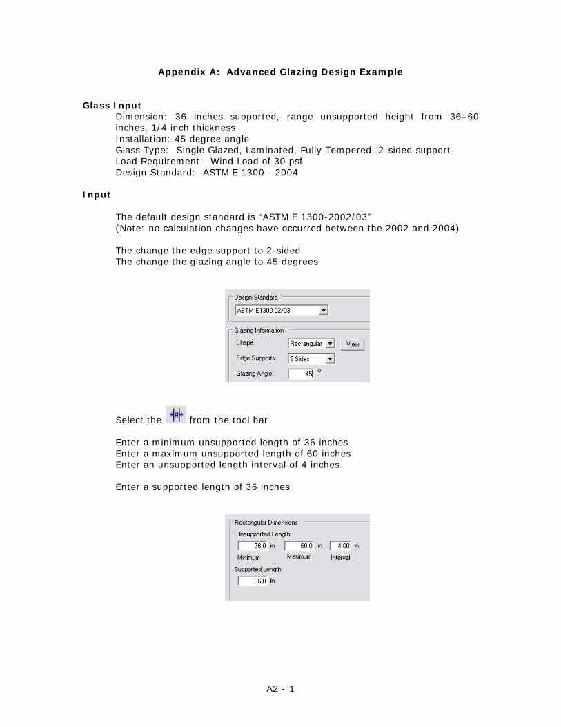
Dimension: 36 inches supported, range unsupported height from 36–60 inches, 1/4 inch thickness Installation: 45 degree angle Glass Type: Single Glazed, Laminated, Fully Tempered, 2-sided support Load Requirement: Wind Load of 30 psf Design Standard: ASTM E 1300 - 2004
Input
The default design standard is “ASTM E 1300-2002/03” (Note: no calculation changes have occurred between the 2002 and 2004) The change the edge support to 2-sided The change the glazing angle to 45 degrees
Select the from the tool bar Enter a minimum unsupported length of 36 inches Enter a maximum unsupported length of 60 inches Enter an unsupported length interval of 4 inches Enter a supported length of 36 inches
A2 - 2
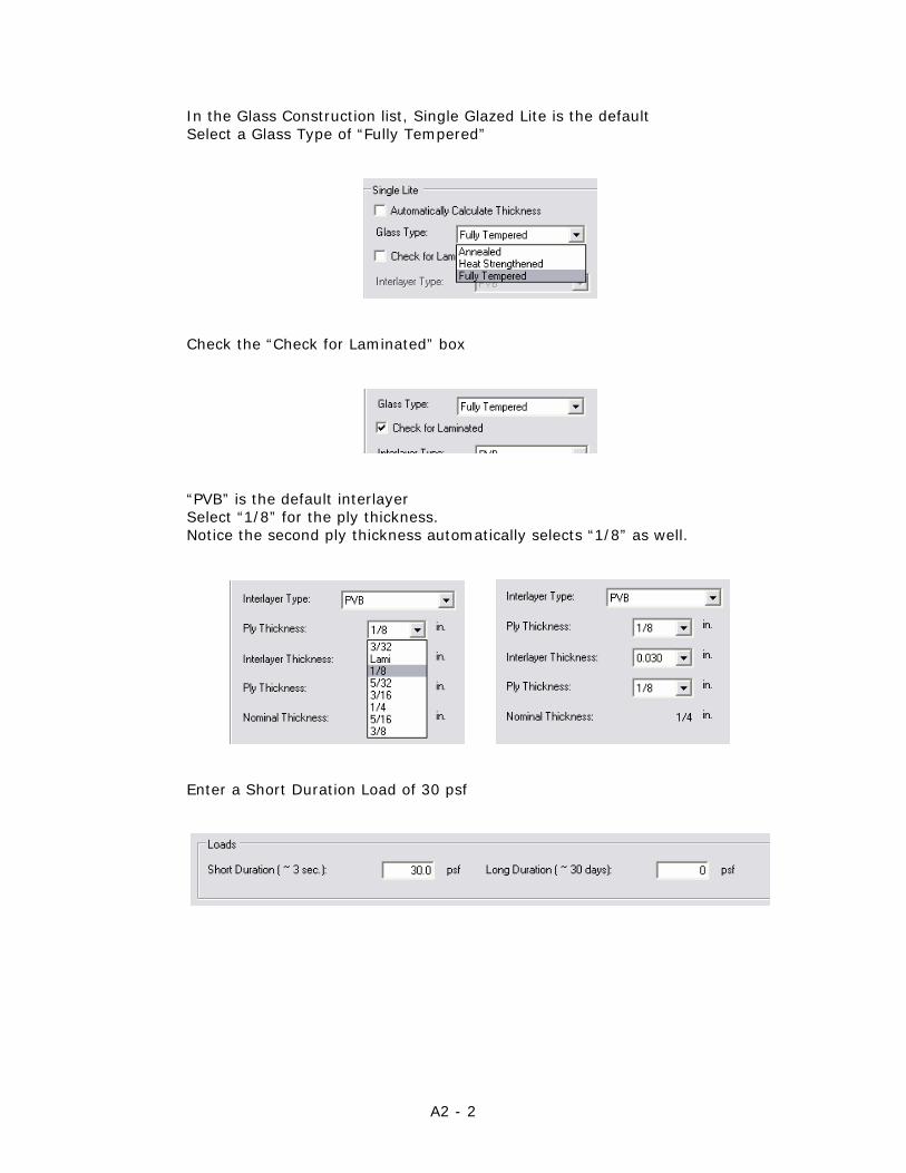
In the Glass Construction list, Single Glazed Lite is the default Select a Glass Type of “Fully Tempered”
Check the “Check for Laminated” box
“PVB” is the default interlayer Select “1/8” for the ply thickness. Notice the second ply thickness automatically selects “1/8” as well.
Enter a Short Duration Load of 30 psf
A2 - 3
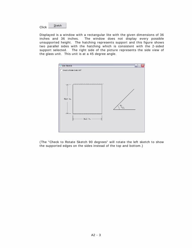
Click
Displayed is a window with a rectangular lite with the given dimensions of 36 inches and 36 inches. The window does not display every possible unsupported height. The hatching represents support and this figure shows two parallel sides with the hatching which is consistent with the 2-sided support selected. The right side of the picture represents the side view of the glass unit. This unit is at a 45 degree angle.
(The “Check to Rotate Sketch 90 degrees” will rotate the left sketch to show the supported edges on the sides instead of the top and bottom.)
A2 - 4
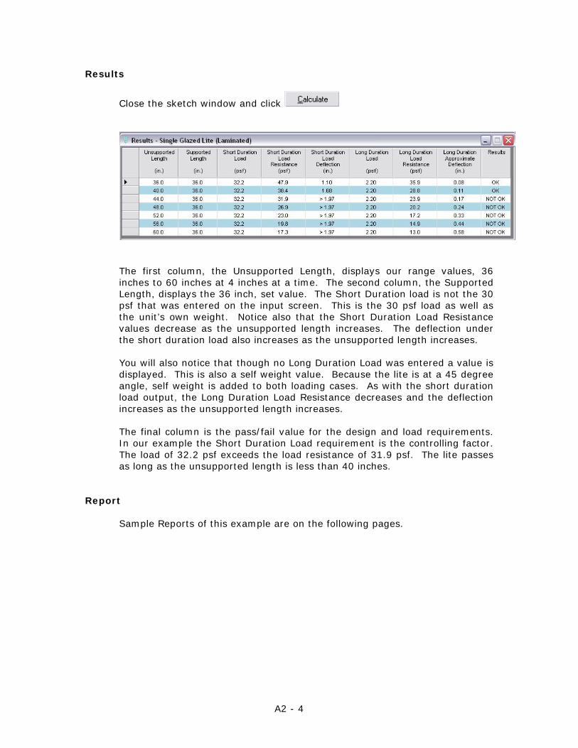
Results
Close the sketch window and click
The first column, the Unsupported Length, displays our range values, 36 inches to 60 inches at 4 inches at a time. The second column, the Supported Length, displays the 36 inch, set value. The Short Duration load is not the 30 psf that was entered on the input screen. This is the 30 psf load as well as the unit’s own weight. Notice also that the Short Duration Load Resistance values decrease as the unsupported length increases. The deflection under the short duration load also increases as the unsupported length increases. You will also notice that though no Long Duration Load was entered a value is displayed. This is also a self weight value. Because the lite is at a 45 degree angle, self weight is added to both loading cases. As with the short duration load output, the Long Duration Load Resistance decreases and the deflection increases as the unsupported length increases. The final column is the pass/fail value for the design and load requirements. In our example the Short Duration Load requirement is the controlling factor. The load of 32.2 psf exceeds the load resistance of 31.9 psf. The lite passes as long as the unsupported length is less than 40 inches.
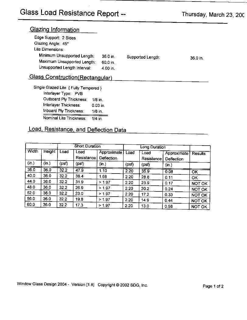
Report
Sample Reports of this example are on the following pages.
A3 - 1
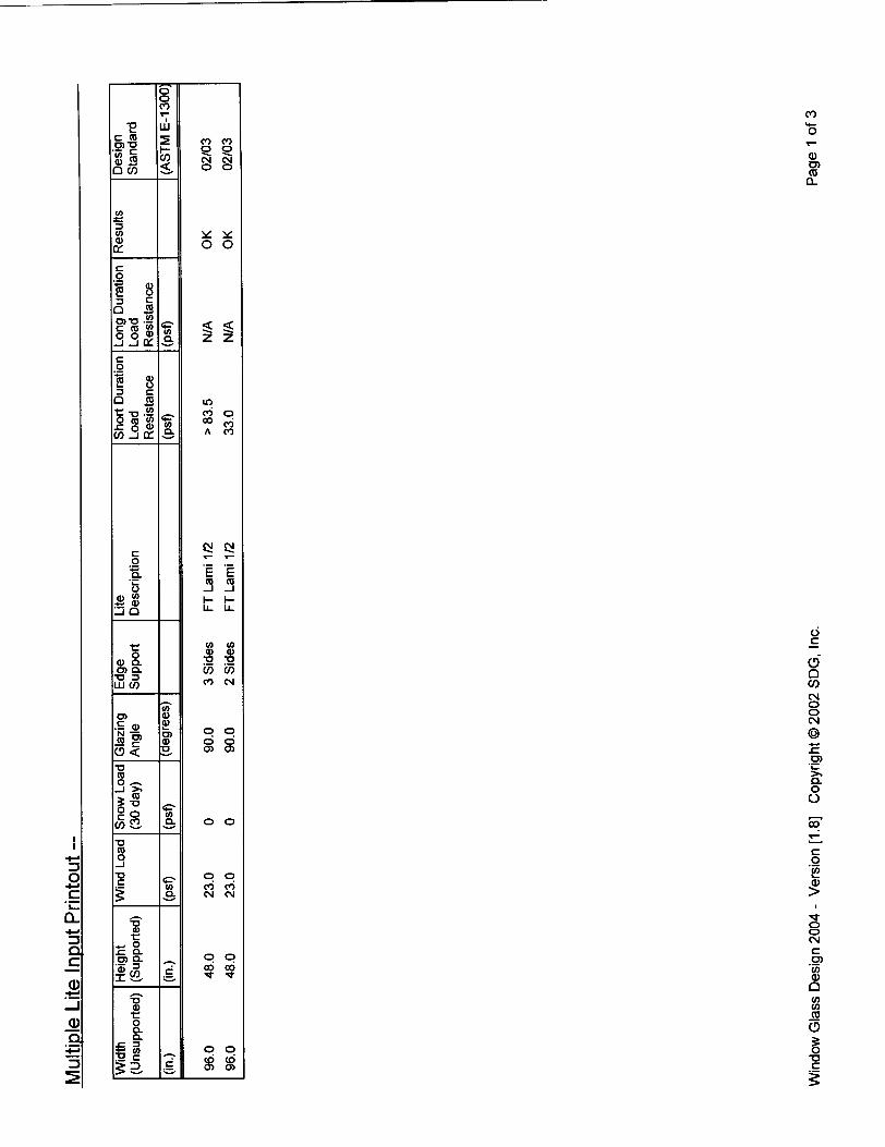
Appendix A: Multiple Glazing Design Example Glass Requirements
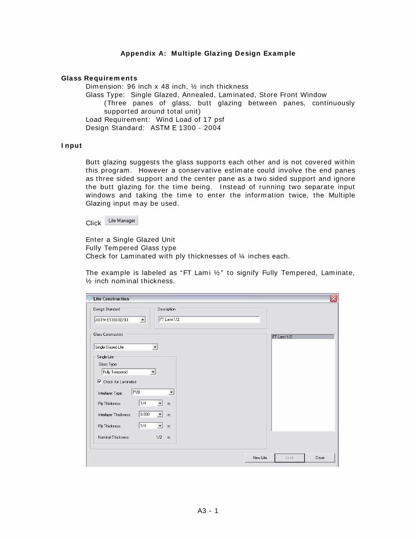
Dimension: 96 inch x 48 inch, ½ inch thickness Glass Type: Single Glazed, Annealed, Laminated, Store Front Window
(Three panes of glass, butt glazing between panes, continuously supported around total unit)
Load Requirement: Wind Load of 17 psf Design Standard: ASTM E 1300 - 2004
Input
Butt glazing suggests the glass supports each other and is not covered within this program. However a conservative estimate could involve the end panes as three sided support and the center pane as a two sided support and ignore the butt glazing for the time being. Instead of running two separate input windows and taking the time to enter the information twice, the Multiple Glazing input may be used.
Click Enter a Single Glazed Unit Fully Tempered Glass type Check for Laminated with ply thicknesses of ¼ inches each. The example is labeled as “FT Lami ½” to signify Fully Tempered, Laminate, ½ inch nominal thickness.
A3 - 2
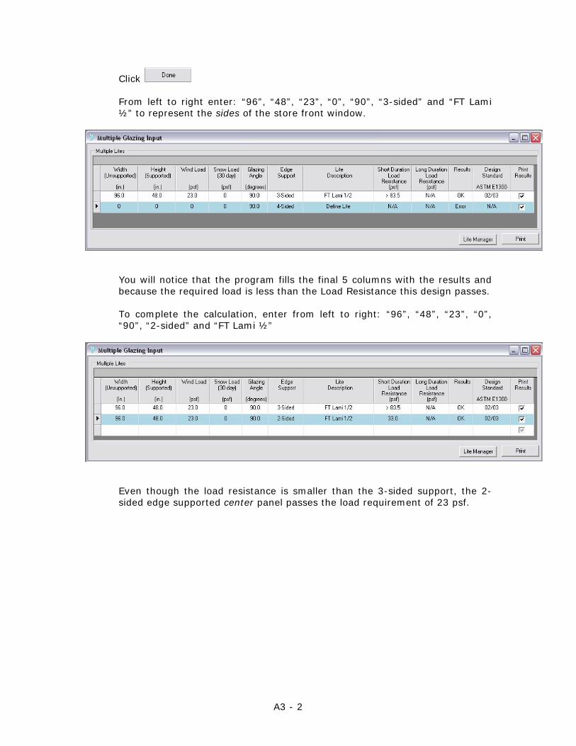
Click From left to right enter: “96”, “48”, “23”, “0”, “90”, “3-sided” and “FT Lami ½” to represent the sides of the store front window.
You will notice that the program fills the final 5 columns with the results and because the required load is less than the Load Resistance this design passes. To complete the calculation, enter from left to right: “96”, “48”, “23”, “0”, “90”, “2-sided” and “FT Lami ½”
Even though the load resistance is smaller than the 3-sided support, the 2-sided edge supported center panel passes the load requirement of 23 psf.
A3 - 3
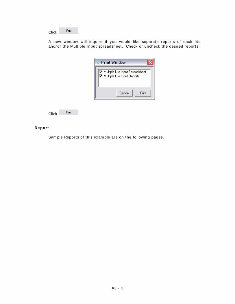
Click A new window will inquire if you would like separate reports of each lite and/or the Multiple Input spreadsheet. Check or uncheck the desired reports.
Click
Report
Sample Reports of this example are on the following pages.