wing 5.x reference - michael · pdf filewing 5.x – best practices & recommendations...
TRANSCRIPT
WiNG 5.X Reference
Best Practices & Recommendations
Part No. TME-02-2013-01 Rev. D

MOTOROLA, MOTO, MOTOROLA SOLUTIONS and the Stylized M Logo are trademarks or registered trademarks of Motorola Trademark Holdings, LLC and are used under license. All other trademarks are
the property of their respective owners.
© 2013 Motorola Solutions, Inc. All Rights Reserved.
Table of Contents
Table of Contents ............................................................................................................................ 3
1. Best Practices / Recommendations ........................................................................................ 4
1.1 3G Adaptor for WWAN ..................................................................................................... 4
1.2 802.11 Data Rates ........................................................................................................... 4
1.3 AP 300 Dependent Access Points ................................................................................... 5
1.4 Access Point Adoption ..................................................................................................... 6
1.5 ADSP .............................................................................................................................. 11
1.6 Antenna Diversity ........................................................................................................... 12
1.7 Broadcast SSID vs. Answer Broadcast Probes............................................................. 12
1.8 Captive Portal ................................................................................................................. 13
1.9 Clustering ....................................................................................................................... 16
1.10 Naming Conventions (Web-UI) ...................................................................................... 17
1.11 Smart-RF ........................................................................................................................ 17
1.12 Stateful Packet Inspection Firewall ................................................................................ 19
1.13 Wireless Client Load Balancing ..................................................................................... 20
1.14 Wireless LANs ................................................................................................................ 21
1.15 Wireless Mesh ................................................................................................................ 22
1.16 Virtual Controller............................................................................................................. 25
1.17 Switched Virtual Interfaces ............................................................................................ 25
1.18 Zero Config IPv4 Address .............................................................................................. 26
1.19 Firmware Upgrades........................................................................................................ 26
WiNG 5.X – Best Practices & Recommendations
Page 4
1. Best Practices / Recommendations
1.1 3G Adaptor for WWAN
Some Wireless Controller and Access Point platforms support a PCI ExpressCard slot allowing a third-party 3G adapter to be installed. This allows the 3G service to be used for Internet access in addition to
providing an alternative path to the corporate network in the event of a primary WAN or internet service provider failure.
It is important to note that some wireless ISPs will terminate the connection if they receive packets whose
source IPv4 address doesn’t match the ISP’s assigned client IPv4 address. Specifically Verizon has been found to do this. If the default gateway is pointed to the WWAN, the Wireless Controller or Access Point may route packets from other hosts out of the WWAN interface which will cause the ISP to
disconnect the session.
There are two ways to resolve this:
1. If the desired default gateway is the wireless ISPs gateway, NAT must be enabled on the
Wireless Controller / Access Point so that the source IPv4 address of the packets is the ISP assigned IPv4 address.
2. If NAT is disabled and IPsec VPN tunneling is enabled, the tunnel ACL defines which traffic is
forwarded over the tunnel. Any traffic that misses the tunnel must be blocked by a separate ACL otherwise it will be forwarded to a gateway IPv4 address outside of the tunnel causing the ISP to disconnect.
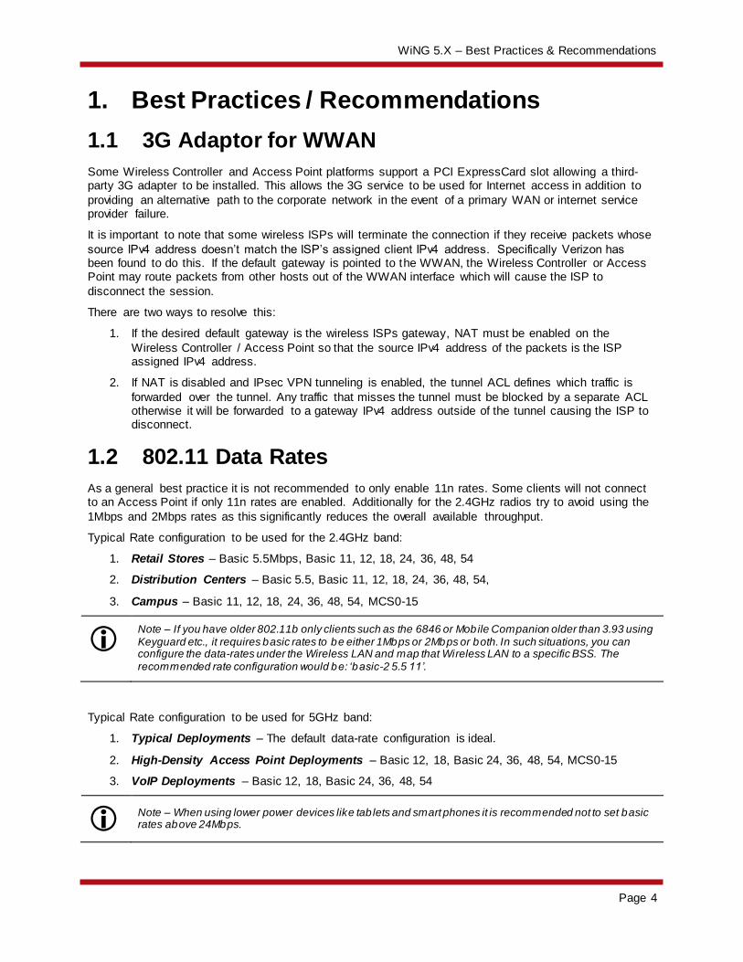
1.2 802.11 Data Rates
As a general best practice it is not recommended to only enable 11n rates. Some clients will not connect to an Access Point if only 11n rates are enabled. Additionally for the 2.4GHz radios try to avoid using the
1Mbps and 2Mbps rates as this significantly reduces the overall available throughput.
Typical Rate configuration to be used for the 2.4GHz band:
1. Retail Stores – Basic 5.5Mbps, Basic 11, 12, 18, 24, 36, 48, 54
2. Distribution Centers – Basic 5.5, Basic 11, 12, 18, 24, 36, 48, 54,
3. Campus – Basic 11, 12, 18, 24, 36, 48, 54, MCS0-15
Note – If you have older 802.11b only clients such as the 6846 or Mobile Companion older than 3.93 using Keyguard etc., it requires basic rates to be either 1Mbps or 2Mbps or both. In such situations, you can configure the data-rates under the Wireless LAN and map that Wireless LAN to a specific BSS. The recommended rate configuration would be: ‘basic-2 5.5 11’.
Typical Rate configuration to be used for 5GHz band:
1. Typical Deployments – The default data-rate configuration is ideal.
2. High-Density Access Point Deployments – Basic 12, 18, Basic 24, 36, 48, 54, MCS0-15
3. VoIP Deployments – Basic 12, 18, Basic 24, 36, 48, 54
Note – When using lower power devices like tab lets and smart phones it is recommended not to set basic rates above 24Mbps.
WiNG 5.X – Best Practices & Recommendations
Page 5
Another new feature in WiNG5.x is to allow probe responses to be sent at a rate different than what the probe request is received. The configuration is under the radio configuration inside an Access Point
profile. It is recommended to use the probe-response rate lowest-basic as the configuration as it will dynamically choose the rates depending on the data rate configuration.
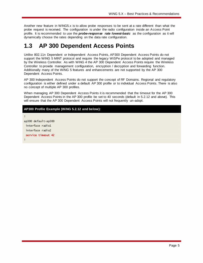
1.3 AP 300 Dependent Access Points
Unlike 802.11n Dependent or Independent Access Points, AP300 Dependent Access Points do not support the WiNG 5 MINT protocol and require the legacy WiSPe protocol to be adopted and managed by the Wireless Controller. As with WiNG 4 the AP 300 Dependent Access Points require the Wireless
Controller to provide management configuration, encryption / decryption and forwarding function. Additionally many of the WiNG 5 features and enhancements are not supported by the AP 300 Dependent Access Points.
AP 300 Independent Access Points do not support the concept of RF Domains. Regional and regulatory configuration is either defined under a default AP 300 profile or to individual Access Points. There is also no concept of multiple AP 300 profiles.
When managing AP 300 Dependent Access Points it is recommended that the timeout for the AP 300 Dependent Access Points in the AP 300 profile be set to 40 seconds (default in 5.2.12 and above). This will ensure that the AP 300 Dependent Access Points will not frequently un-adopt.
AP300 Profile Example (WiNG 5.2.12 and below):
!
ap300 default-ap300
interface radio1
interface radio2
service timeout 42
!
WiNG 5.X – Best Practices & Recommendations
Page 6
1.4 Access Point Adoption
1.4.1 DHCP
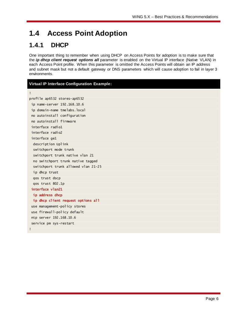
One important thing to remember when using DHCP on Access Points for adoption is to make sure that the ip dhcp client request options all parameter is enabled on the Virtual IP interface (Native VLAN) in each Access Point profile. When this parameter is omitted the Access Points will obtain an IP address
and subnet mask but not a default gateway or DNS parameters which will cause adoption to fail in layer 3 environments.
Virtual IP Interface Configuration Example:
!
profile ap6532 stores-ap6532
ip name-server 192.168.10.6
ip domain-name tmelabs.local
no autoinstall configuration
no autoinstall firmware
interface radio1
interface radio2
interface ge1
description Uplink
switchport mode trunk
switchport trunk native vlan 21
no switchport trunk native tagged
switchport trunk allowed vlan 21-25
ip dhcp trust
qos trust dscp
qos trust 802.1p
interface vlan21
ip address dhcp
ip dhcp client request options all
use management-policy stores
use firewall-policy default
ntp server 192.168.10.6
service pm sys-restart
!
WiNG 5.X – Best Practices & Recommendations
Page 7
1.4.2 Pre-Staging
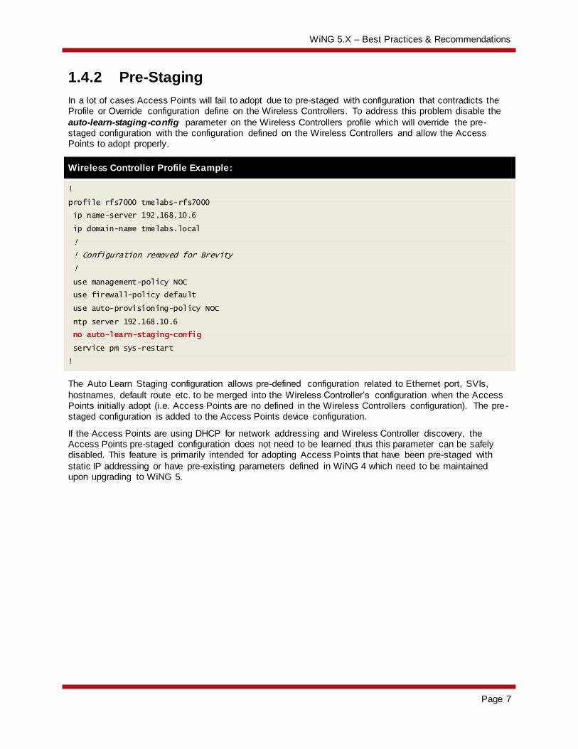
In a lot of cases Access Points will fail to adopt due to pre-staged with configuration that contradicts the Profile or Override configuration define on the Wireless Controllers. To address this problem disable the
auto-learn-staging-config parameter on the Wireless Controllers profile which will override the pre-staged configuration with the configuration defined on the Wireless Controllers and allow the Access Points to adopt properly.
Wireless Controller Profile Example:
!
profile rfs7000 tmelabs-rfs7000
ip name-server 192.168.10.6
ip domain-name tmelabs.local
!
! Configuration removed for Brevity
!
use management-policy NOC
use firewall-policy default
use auto-provisioning-policy NOC
ntp server 192.168.10.6
no auto-learn-staging-config
service pm sys-restart
!
The Auto Learn Staging configuration allows pre-defined configuration related to Ethernet port, SVIs,
hostnames, default route etc. to be merged into the Wireless Controller’s configuration when the Access Points initially adopt (i.e. Access Points are no defined in the Wireless Controllers configuration). The pre-staged configuration is added to the Access Points device configuration.
If the Access Points are using DHCP for network addressing and Wireless Controller discovery, the Access Points pre-staged configuration does not need to be learned thus this parameter can be safely disabled. This feature is primarily intended for adopting Access Points that have been pre-staged with
static IP addressing or have pre-existing parameters defined in WiNG 4 which need to be maintained upon upgrading to WiNG 5.

WiNG 5.X – Best Practices & Recommendations
Page 8
1.4.3 MINT Link Levels
One major source of confusion in the field is that level 2 MINT links are required to adopt Access Points in layer 3 environments (i.e. an IP router is installed between the Wireless Controller and Access Points).
Level 2 MINT links are NOT required for layer 3 Access Point adoption as Access Points can adopt using level 1 IP based MINT links.
Level 1 MINT links are typically used in the following Wireless LAN deployment scenarios:
1. Campus environments with up to 256 Access Points (all or some of the WLANs tunneling traffic to the Wireless Controllers). In this case an Access Point cannot be the elected RF Domain Manager when more than 24 x Single Radio / 64 x Dual Radio Access Points are present in the
RF Domain. The Wireless Controller has to be the elected RF Domain Manager for the site so a level 1 MINT links have to be utilized.
Additionally the some or all of the WLANs are tunneling traffic to the Wireless Controllers which
requires a level 1 MINT links. Extended VLANs are not supported over level 2 MINT links!
2. Campus environments with 500 to 1,000 Access Points (all WLANs using local bridging). In this case an Access Point cannot be the elected RF Domain Manager for the site as you have more
than 24 x Single Radio / 64 x Dual Radio Access Points in the RF Domain. The Wireless Controller has to be the elected RF Domain Manager for the site so a level 1 MINT links have to be utilized.
Note: We are able to scale to a larger number of Access Points as tunneling is involved.
Note – We are able to scale beyond 256 Access Points as no extended VLANs are involved.
Level 2 MINT links are used for large distributed deployments with centralized Wireless Controllers and
remote Access Points where for scaling you need to have remote Access Points at each site to be MINT isolated form Access Points at other sites. In most distributed environments (multiple retail stores, branch offices, distribution centers etc.) with fewer than 24 x Single Radio / 64 x Dual Radio Access Points we
utilize level 2 MINT links.
With the NX 9000 series Wireless Controller we can scale to support 10,240 remote Access Points by utilizing level 2 MINT links. Level 2 MINT links ensures you have very limited WAN overhead (i.e. one Access Point per remote site communicating with the Wireless Controllers in the data center / NOC). In
addition level 2 MINT links provides MINT isolation between the multiple RF Domains / Sites. Access Points at one site cannot see Access Points at other remote sites.
Note – If you have extended VLANs, you cannot use level 2 MINT links and will have to deploy level 1 MINT links. The NX 9000 / 9500 series Wireless Controllers cannot be deployed as they have no data -plane. In this case the RFS 7000 series Wireless Controllers will have to be deployed which reduces the number of remote Access Points supported per controller to 256.
WiNG 5.X – Best Practices & Recommendations
Page 9
1.4.4 Control VLAN vs. Controller VLAN
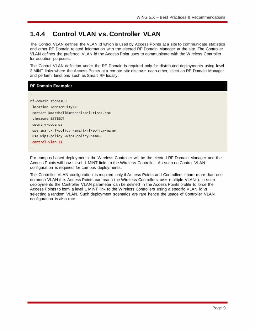
The Control VLAN defines the VLAN id which is used by Access Points at a site to communicate statistics and other RF Domain related information with the elected RF Domain Manager at the site. The Controller
VLAN defines the preferred VLAN id the Access Point uses to communicate with the Wireless Controller for adoption purposes.
The Control VLAN definition under the RF Domain is required only for distributed deployments using level
2 MINT links where the Access Points at a remote site discover each-other, elect an RF Domain Manager and perform functions such as Smart RF locally.
RF Domain Example:
!
rf-domain store100
location JohnsonCityTN
contact [email protected]
timezone EST5EDT
country-code us
use smart-rf-policy <smart-rf-policy-name>
use wips-policy <wips-policy-name>
control-vlan 11
!
For campus based deployments the Wireless Controller will be the elected RF Domain Manager and the
Access Points will have level 1 MINT links to the Wireless Controller. As such no Control VLAN configuration is required for campus deployments.
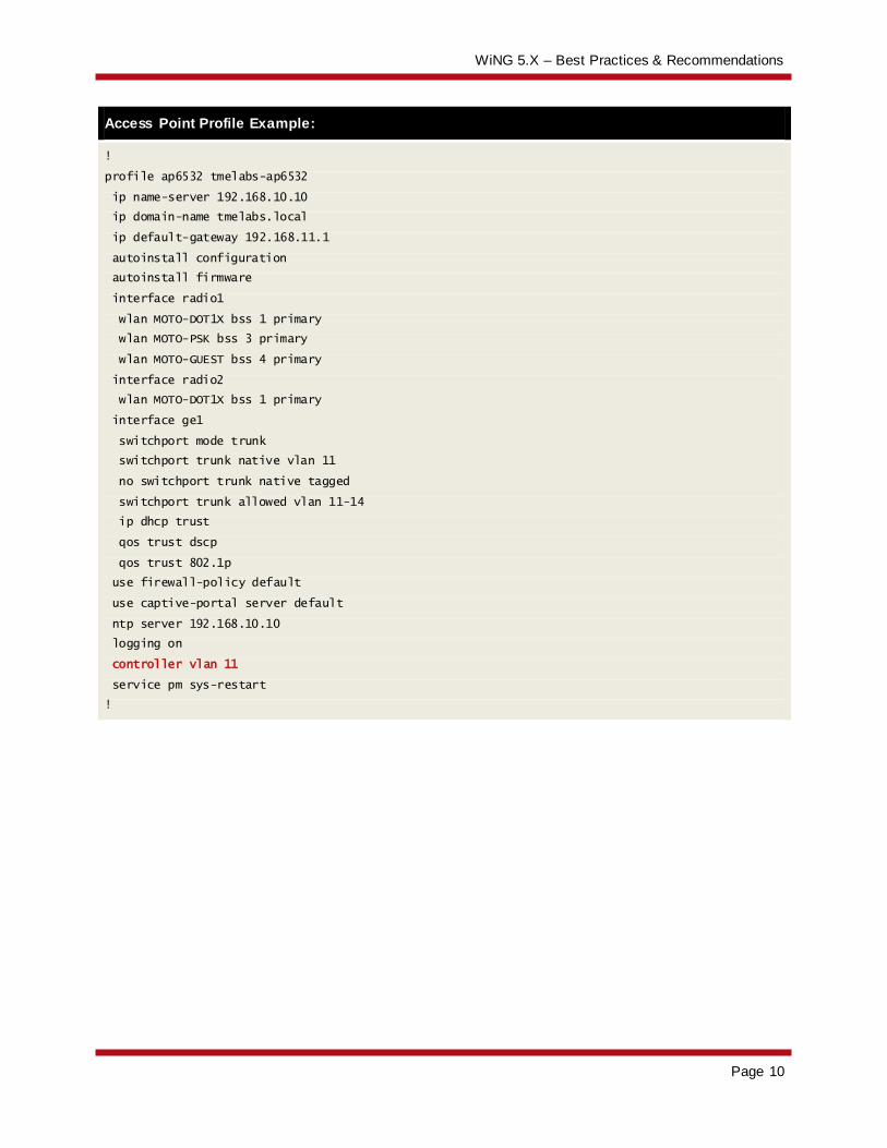
The Controller VLAN configuration is required only if Access Points and Controllers share more than one
common VLAN (i.e. Access Points can reach the Wireless Controllers over multiple VLANs). In such deployments the Controller VLAN parameter can be defined in the Access Points profile to force the Access Points to form a level 1 MINT link to the Wireless Controllers using a specific VLAN id vs.
selecting a random VLAN. Such deployment scenarios are rare hence the usage of Controller VLAN configuration is also rare.
WiNG 5.X – Best Practices & Recommendations
Page 10
Access Point Profile Example:
!
profile ap6532 tmelabs-ap6532
ip name-server 192.168.10.10
ip domain-name tmelabs.local
ip default-gateway 192.168.11.1
autoinstall configuration
autoinstall firmware
interface radio1
wlan MOTO-DOT1X bss 1 primary
wlan MOTO-PSK bss 3 primary
wlan MOTO-GUEST bss 4 primary
interface radio2
wlan MOTO-DOT1X bss 1 primary
interface ge1
switchport mode trunk
switchport trunk native vlan 11
no switchport trunk native tagged
switchport trunk allowed vlan 11-14
ip dhcp trust
qos trust dscp
qos trust 802.1p
use firewall-policy default
use captive-portal server default
ntp server 192.168.10.10
logging on
controller vlan 11
service pm sys-restart
!
WiNG 5.X – Best Practices & Recommendations
Page 11
1.5 ADSP
Several things to remember when working with WiNG 5 and ADSP:
1. SNMP Timeout – By default ADSP is using sub second timeout for SNMP responses. Depending
on the size of the wireless network – we recommend increasing that number to 10 seconds.
2. Poll Interval – We recommend setting poll interval to 30 minutes – not 5 minutes. 5 minutes default interval is too short to walk the whole table and will overload the Wireless Controller with
too many SNMP requests.
When using Wireless Controllers we recommend that you configure ADSP to only poll the Wireless Controllers. It is not recommended that you poll the Access Points directly. The Wireless Controllers have
all the required information and statistics so there is no need to query each Access Point individually.
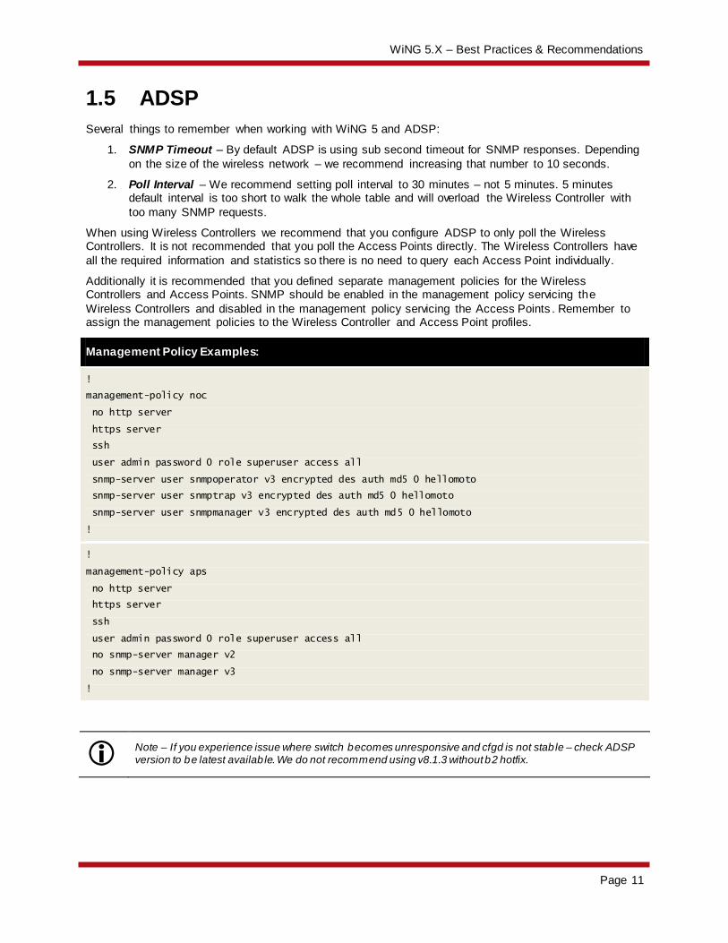
Additionally it is recommended that you defined separate management policies for the Wireless Controllers and Access Points. SNMP should be enabled in the management policy servicing the
Wireless Controllers and disabled in the management policy servicing the Access Points . Remember to assign the management policies to the Wireless Controller and Access Point profiles.
Management Policy Examples:
!
management-policy noc
no http server
https server
ssh
user admin password 0 role superuser access all
snmp-server user snmpoperator v3 encrypted des auth md5 0 hellomoto
snmp-server user snmptrap v3 encrypted des auth md5 0 hellomoto
snmp-server user snmpmanager v3 encrypted des auth md5 0 hellomoto
!
!
management-policy aps
no http server
https server
ssh
user admin password 0 role superuser access all
no snmp-server manager v2
no snmp-server manager v3
!
Note – If you experience issue where switch becomes unresponsive and cfgd is not stab le – check ADSP version to be latest availab le. We do not recommend using v8.1.3 without b2 hotfix.
WiNG 5.X – Best Practices & Recommendations
Page 12
1.6 Antenna Diversity
When using 802.11n Access Points and clients it is not recommended to configure antenna diversity. 802.11n already has a provision for diversity so enabling diversity will affect 802.11n transmissions.
1.7 Broadcast SSID vs. Answer Broadcast Probes
WiNG 4 and WiNG 5 supports the ability to enable / disable broadcast SSID and answer broadcast probes. These parameters are enabled / disabled per Wireless LAN:
1. Broadcast SSID – If enabled the Access Point radios includes the ESSID in the beacon. If disabled the Access Point omits the ESSID from the beacon. When beacon doesn’t include the ESSID mobile clients usually send probes on to the air to find suitable Access Points. Therefore
overall broadcast traffic is increased thus reducing total available airtime. When performance is an issue we don’t recommend disabling the ESSID in the beacon.
2. Answer Broadcast Probes – If enabled the Access Point will send a probe-response when a
wireless client sends a broadcast probe. A lot of clients even if configured for specific ESSID will still send broadcast probes (i.e. probe requests with no ESSID). This will cause the Access Point to respond on each BSS where Wireless LAN is set to answer broadcast probes. When
performance is an issue we recommend disabling the feature and don’t answer broadcast probes. The usual case where answering broadcast probes might needed guest access (i.e. captive portal).
In most cases, if broadcast SSID is enabled (i.e. the ESSID is advertised in the beacon) you can safely disable answer broadcast probes. It is recommended to disable answer broadcast probes as it helps reducing probe responses going out from Access Points at lower data rates for all probes sent out by
client devices (including devices that are not part of the customer network).
For Apple and Android devices like tablets, smart-phones and PDAs, it is recommended that broadcast SSID be enabled as the broadcasting of the SSID in the beacon is a requirement on these devices for
roaming to be reliable.
WiNG 5.X – Best Practices & Recommendations
Page 13
1.8 Captive Portal
1.8.1 Captive Portal Service
One common mistake with Captive Portal deployments is to not assign the Captive Portal service to the device(s) that are providing the capture and redirection or assigning the Captive Portal service to the wrong device:
1. When the Captive Portal is operating on one or more Access Points at a site, the Captive Portal service must be assigned to the Access Points Profile or to individual Access Points as Overrides.
2. When the Captive Portal service is operating on one or more centralized Wireless Controllers, the Captive Portal service must be assigned to the Wireless Controllers Profile or to individual Wireless Controllers as Overrides.
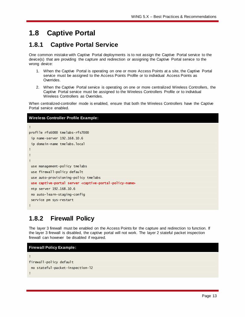
When centralized-controller mode is enabled, ensure that both the Wireless Controllers have the Captive Portal service enabled.
Wireless Controller Profile Example:
!
profile rfs6000 tmelabs-rfs7000
ip name-server 192.168.10.6
ip domain-name tmelabs.local
!
!
!
use management-policy tmelabs
use firewall-policy default
use auto-provisioning-policy tmelabs
use captive-portal server <captive-portal-policy-name>
ntp server 192.168.10.6
no auto-learn-staging-config
service pm sys-restart
!
1.8.2 Firewall Policy
The layer 3 firewall must be enabled on the Access Points for the capture and redirection to function. If the layer 3 firewall is disabled, the captive portal will not work. The layer 2 stateful packet inspection
firewall can however be disabled if required.
Firewall Policy Example:
!
firewall-policy default
no stateful-packet-inspection-l2
!
WiNG 5.X – Best Practices & Recommendations
Page 14
1.8.3 Firewall Rules
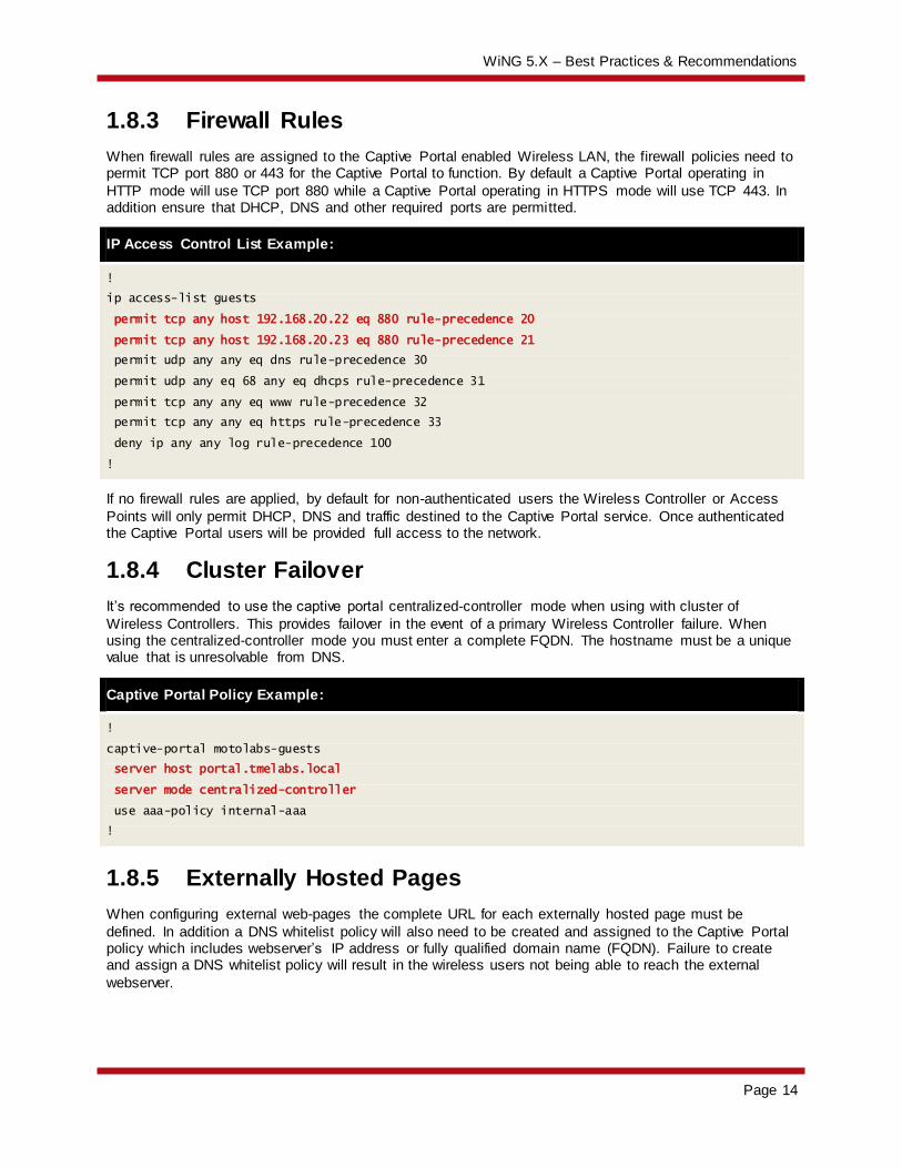
When firewall rules are assigned to the Captive Portal enabled Wireless LAN, the firewall policies need to permit TCP port 880 or 443 for the Captive Portal to function. By default a Captive Portal operating in
HTTP mode will use TCP port 880 while a Captive Portal operating in HTTPS mode will use TCP 443. In addition ensure that DHCP, DNS and other required ports are permitted.
IP Access Control List Example:
!
ip access-list guests
permit tcp any host 192.168.20.22 eq 880 rule-precedence 20
permit tcp any host 192.168.20.23 eq 880 rule-precedence 21
permit udp any any eq dns rule-precedence 30
permit udp any eq 68 any eq dhcps rule-precedence 31
permit tcp any any eq www rule-precedence 32
permit tcp any any eq https rule-precedence 33
deny ip any any log rule-precedence 100
!
If no firewall rules are applied, by default for non-authenticated users the Wireless Controller or Access
Points will only permit DHCP, DNS and traffic destined to the Captive Portal service. Once authenticated the Captive Portal users will be provided full access to the network.
1.8.4 Cluster Failover
It’s recommended to use the captive portal centralized-controller mode when using with cluster of
Wireless Controllers. This provides failover in the event of a primary Wireless Controller failure. When using the centralized-controller mode you must enter a complete FQDN. The hostname must be a unique value that is unresolvable from DNS.
Captive Portal Policy Example:
!
captive-portal motolabs-guests
server host portal.tmelabs.local
server mode centralized-controller
use aaa-policy internal-aaa
!
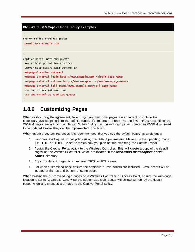
1.8.5 Externally Hosted Pages
When configuring external web-pages the complete URL for each externally hosted page must be
defined. In addition a DNS whitelist policy will also need to be created and assigned to the Captive Portal policy which includes webserver’s IP address or fully qualified domain name (FQDN). Failure to create and assign a DNS whitelist policy will result in the wireless users not being able to reach the external
webserver.
WiNG 5.X – Best Practices & Recommendations
Page 15
DNS Whitelist & Captive Portal Policy Examples:
!
dns-whitelist motolabs-guests
permit www.example.com
!
!
captive-portal motolabs-guests
server host portal.tmelabs.local
server mode centralized-controller
webpage-location external
webpage external login http://www.example.com /<login-page-name>
webpage external welcome http://www.example.com/<welcome-page-name>
webpage external fail http://www.example.com/fail-page-name>
use aaa-policy internal-aaa
use dns-whitelist motolabs-guests
!
1.8.6 Customizing Pages
When customizing the agreement, failed, login and welcome pages it is important to include the necessary java scripting from the default pages. It’s important to note that the java scripts required for the WiNG 4 pages are not compatible with WiNG 5. Any customized login pages created in WiNG 4 will need
to be updated before they can be implemented in WiNG 5.
When creating customized pages it is recommended that you use the default pages as a reference:
1. First create a Captive Portal policy using the default parameters. Make sure the operating mode
(i.e. HTTP or HTTPS) is set to match how you plan on implementing the Captive Portal.
2. Assign the Captive Portal policy to the Wireless Controller. This will create a copy of the default pages on the Wireless Controller which are located in the flash://hostspot/<captive-portal-
name> directory.
3. Copy the default pages to an external TFTP or FTP server.
4. For each customized page ensure the appropriate java scripts are included. Java scripts will be
located at the top and bottom of some pages.
When hosting the customized login pages on a Wireless Controller or Access Point, ensure the web-page location is set to Advanced. Otherwise the customized login pages will be overwritten by the default
pages when any changes are made to the Captive Portal policy.
WiNG 5.X – Best Practices & Recommendations
Page 16
1.9 Clustering
1.9.1 Access Point Failover & Recovery
By default in an Active / Standby cluster environment during an Active Controller failure, the Access Points will stay adopted to the Standby Controller after the Active Controller has recovered. Reverting the Access Points requires the Access Points to be manually un-adopted using the no adoption command
on the Standby Controller.
Automatic reversion of the Access Points to the Active Controller can be optionally enabled by defining the cluster force-configured-state and cluster force-configured-state-delay <time-in-mins>
parameters in the Controller Profiles or directly on the Controllers device configuration as Overrides. It is recommended however that the cluster force-configured-state-delay value be set to a conservative value to prevent flapping in the event that the Active Controller is repeatedly loosing connectivity or goes
offline.
1.9.2 MINT Levels
When defining a cluster of Wireless Controllers, all members of the cluster MUST be configured to use
the same MINT level. Do not define cluster members at different MINT levels! Select level 1 or level 2 depending on your specific deployment:
1. For campus based deployments the cluster should be formed using level 1 MINT links.
2. For distributed deployments over a WAN (one or more extended VLANs), the cluster should be formed using level 1 MINT links.
3. For distributed deployments over a WAN (locally bridged tunneled VLANs), the cluster should be
formed using level 2 MINT links.
1.9.3 Cluster Failover
When using tunneled VLANs and clustering it is recommended that the cluster communication / Access
Point adoption and user VLANs NOT be assigned to different physical ports on the Wireless Controllers (i.e. Access Point adoption, cluster communications and management VLANs on Ge1 and extended VLANs on Ge2).
To prevent network loops only one Wireless Controller can be designated as the EVIS to forward
tunneled VLAN traffic onto the wired network at a time. The Wireless Controllers are able to see each other (in most cases) over the tunneled VLANs and the alternative Wireless Controller will not take the EVIS role as long as it can see the first Wireless Controller over the tunneled VLAN(s).
If the cluster communication and tunneled VLANs are split between ports on the Wireless Controller you can run into issues during cluster failure scenarios. For example during normal operation the primary Wireless Controller adopts the Access Points and is the EVIS for the tunneled WLANs. A network failure
disables communications on the Ge port on the primary Wireless Controller where the Access Point adoption, cluster and management VLANs reside.
The cluster protocol will go down and the Access Points will failover to the alternate Wireless Controller,
however as the Wireless Controllers can still see each other over the tunneled VLANs the EVIS will not failover. The wireless user traffic will still be forwarded to the primary Wireless Controller which may not have access to the backbone.
WiNG 5.X – Best Practices & Recommendations
Page 17
As a best practice for clustering and failover it is recommended that:
1. All VLANs (Access Point adoption, cluster, management and user VLANs) be assigned to a
common physical port on each Wireless Controller.
2. If additional capacity or availability is required it is recommended that 802.3ad static Link Aggregation (i.e. Port Channel) be enabled with all the VLANs (Access Point adoption, cluster,
management and user VLANs) assigned as members of the Link Aggregation Group (LAG).
1.10 Naming Conventions (Web-UI)
When creating objects such as RF Domains, Profiles, Policies and ACLs within the Web-UI, it is strongly
recommended that no spaces are used to name the objects. Using spaces adds control characters to the object name in the configuration which can be difficult to decipher and can cause errors in the configuration or operation of the system. As an alternative it is recommended that you use hyphens or
underscore characters which will result in a cleaner configuration.
1.11 Smart-RF
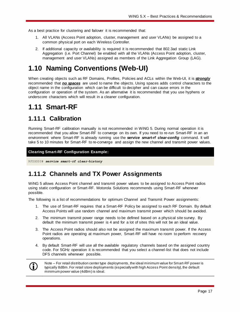
1.11.1 Calibration
Running Smart-RF calibration manually is not recommended in WiNG 5. During normal operation it is recommended that you allow Smart-RF to converge on its own. If you need to re-run Smart-RF in an an
environment where Smart-RF is already running use the service smart-rf clear-config command. It will take 5 to 10 minutes for Smart-RF to re-converge and assign the new channel and transmit power values.
Clearing Smart-RF Configuration Example:
RFSX000# service smart-rf clear-history
1.11.2 Channels and TX Power Assignments
WiNG 5 allows Access Point channel and transmit power values to be assigned to Access Point radios using static configuration or Smart-RF. Motorola Solutions recommends using Smart-RF whenever
possible.
The following is a list of recommendations for optimum Channel and Transmit Power assignments:
1. The use of Smart-RF requires that a Smart-RF Policy be assigned to each RF Domain. By default
Access Points will use random channel and maximum transmit power which should be avoided.
2. The minimum transmit power range needs to be defined based on a physical site survey. By default the minimum transmit power is 4 and for a lot of sites this will not be an ideal value.
3. The Access Point radios should also not be assigned the maximum transmit power. If the Access Point radios are operating at maximum power, Smart-RF will have no room to perform recovery operations.
4. By default Smart-RF will use all the available regulatory channels based on the assigned country code. For 5GHz operation it is recommended that you select a channel-list that does not include DFS channels whenever possible.
Note – For retail distribution center type deployments, the ideal minimum value for Smart-RF power is typically 8dBm. For retail store deployments (especially with high Access Point density), the default minimum power value (4dBm) is ideal.

WiNG 5.X – Best Practices & Recommendations
Page 18
1.11.3 Coverage Hole Recovery
The coverage hole recovery feature is required only for deployments where Access Point density/overlap is not optimal and there could be potential coverage holes in the network. In most cases these situations
arise when customers perform a one for one Access Point replacement from a legacy low density 802.11b or 802.11bg deployments.
If the client density is high, it is recommended that you increase the coverage hole recovery client
threshold. Using the default values will initiate coverage hole recovery if one client is below the SNR threshold.
For greenfield or new replacements performed using a site survey with -65dBm or -70dBm coverage
requirement with 15 to 20% overlap, the coverage hole recovery feature is not required. If enabled it should be configured with a client threshold of 3 to 5 clients.
1.11.4 Smart Off Channel Scanning (OCS)
For retail deployments with handheld devices using terminal emulation applications such as wave-link, it
is recommended to use the smart-ocs-monitoring <band> power-save-aware strict mode.
Smart-RF Smart Off Channel Scanning Example:
RFSX000(config-smart-rf-policy-default)# smart-ocs-monitoring power-save-aware 2.4GHz strict
1.11.5 Example Smart-RF Policy
The following is a typical Smart-RF policy if coverage hole recovery is not required:
Typical Smart-RF Policy Example:
!
smart-rf-policy stores
sensitivity custom
assignable-power 5GHz min 5
assignable-power 2.4GHz min 5
channel-list 5GHz 36,40,44,48,52,56,60,64,149,153,157,161
smart-ocs-monitoring sample-count 5GHz 10
smart-ocs-monitoring sample-count 2.4GHz 15
smart-ocs-monitoring power-save-aware 2.4GHz strict
interference-recovery client-threshold 20
no coverage-hole-recovery
coverage-hole-recovery client-threshold 5GHz 3
coverage-hole-recovery client-threshold 2.4GHz 5
neighbor-recovery dynamic-sampling
!
WiNG 5.X – Best Practices & Recommendations
Page 19
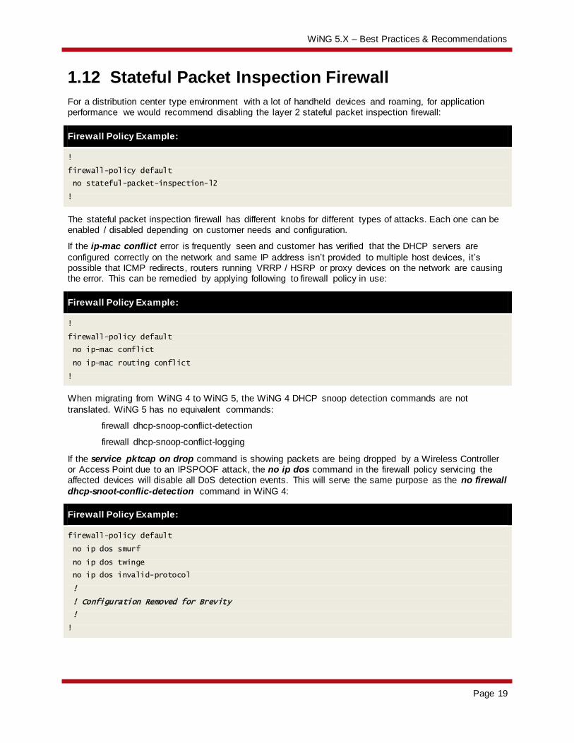
1.12 Stateful Packet Inspection Firewall
For a distribution center type environment with a lot of handheld devices and roaming, for application performance we would recommend disabling the layer 2 stateful packet inspection firewall:
Firewall Policy Example:
!
firewall-policy default
no stateful-packet-inspection-l2
!
The stateful packet inspection firewall has different knobs for different types of attacks. Each one can be enabled / disabled depending on customer needs and configuration.
If the ip-mac conflict error is frequently seen and customer has verified that the DHCP servers are
configured correctly on the network and same IP address isn’t provided to multiple host devices, it’s possible that ICMP redirects, routers running VRRP / HSRP or proxy devices on the network are causing the error. This can be remedied by applying following to firewall policy in use:
Firewall Policy Example:
!
firewall-policy default
no ip-mac conflict
no ip-mac routing conflict
!
When migrating from WiNG 4 to WiNG 5, the WiNG 4 DHCP snoop detection commands are not
translated. WiNG 5 has no equivalent commands:
firewall dhcp-snoop-conflict-detection
firewall dhcp-snoop-conflict-logging
If the service pktcap on drop command is showing packets are being dropped by a Wireless Controller or Access Point due to an IPSPOOF attack, the no ip dos command in the firewall policy servicing the affected devices will disable all DoS detection events. This will serve the same purpose as the no firewall
dhcp-snoot-conflic-detection command in WiNG 4:
Firewall Policy Example:
firewall-policy default
no ip dos smurf
no ip dos twinge
no ip dos invalid-protocol
!
! Configuration Removed for Brevity
!
!
WiNG 5.X – Best Practices & Recommendations
Page 20
1.13 Wireless Client Load Balancing
Wireless client load-balancing is not enabled by default. It needs to be properly configured with full understanding of the exact needs and purpose for doing load-balancing.
There are two main ways to load-balance wireless clients:
1. Between Bands (Band Steering)
2. Between Access Points (Load-Balancing)
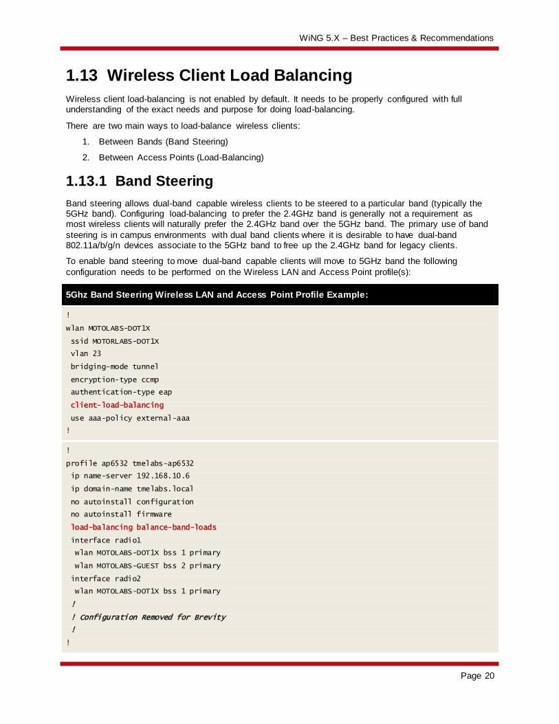
1.13.1 Band Steering
Band steering allows dual-band capable wireless clients to be steered to a particular band (typically the 5GHz band). Configuring load-balancing to prefer the 2.4GHz band is generally not a requirement as most wireless clients will naturally prefer the 2.4GHz band over the 5GHz band. The primary use of band
steering is in campus environments with dual band clients where it is desirable to have dual-band 802.11a/b/g/n devices associate to the 5GHz band to free up the 2.4GHz band for legacy clients.
To enable band steering to move dual-band capable clients will move to 5GHz band the following
configuration needs to be performed on the Wireless LAN and Access Point profile(s):
5Ghz Band Steering Wireless LAN and Access Point Profile Example:
!
wlan MOTOLABS-DOT1X
ssid MOTORLABS-DOT1X
vlan 23
bridging-mode tunnel
encryption-type ccmp
authentication-type eap
client-load-balancing
use aaa-policy external-aaa
!
!
profile ap6532 tmelabs-ap6532
ip name-server 192.168.10.6
ip domain-name tmelabs.local
no autoinstall configuration
no autoinstall firmware
load-balancing balance-band-loads
interface radio1
wlan MOTOLABS-DOT1X bss 1 primary
wlan MOTOLABS-GUEST bss 2 primary
interface radio2
wlan MOTOLABS-DOT1X bss 1 primary
!
! Configuration Removed for Brevity
!
!
WiNG 5.X – Best Practices & Recommendations
Page 21
1.13.2 Access Point Load Balancing
The primary use of load-balancing between Access Points is for auditorium and stadium environments with a high concentration of wireless clients. Load balancing is required to distribute the wireless clients
between the Access Point radios to reduce overloading a single Access Point. It’s also important to have a high Access Point density in the area where load-balancing is configured so wireless clients will have good signal connecting to any Access Point configured for load-balancing.
If load balancing needs to be configured in an auditorium it is recommended that the load-balancing group-id parameter and value be defined in the Access Point profile servicing the Access Points in the auditorium. Load-balancing also needs to be enabled in the Wireless LANs to indicate with Wireless
LANs support load-balancing.
1.14 Wireless LANs
When mapping VLANs to Wireless LANs make sure that same VLAN is not configured for a tunneled and locally bridged WLAN. This is not a valid configuration. A VLAN’s bridging mode can either be tunnel or
locally bridged but not both.
Additionally if an Access Point is adopted over an IP based level 2 MINT link, tunneling of VLANs is not supported.
WiNG 5.X – Best Practices & Recommendations
Page 22
1.15 Wireless Mesh
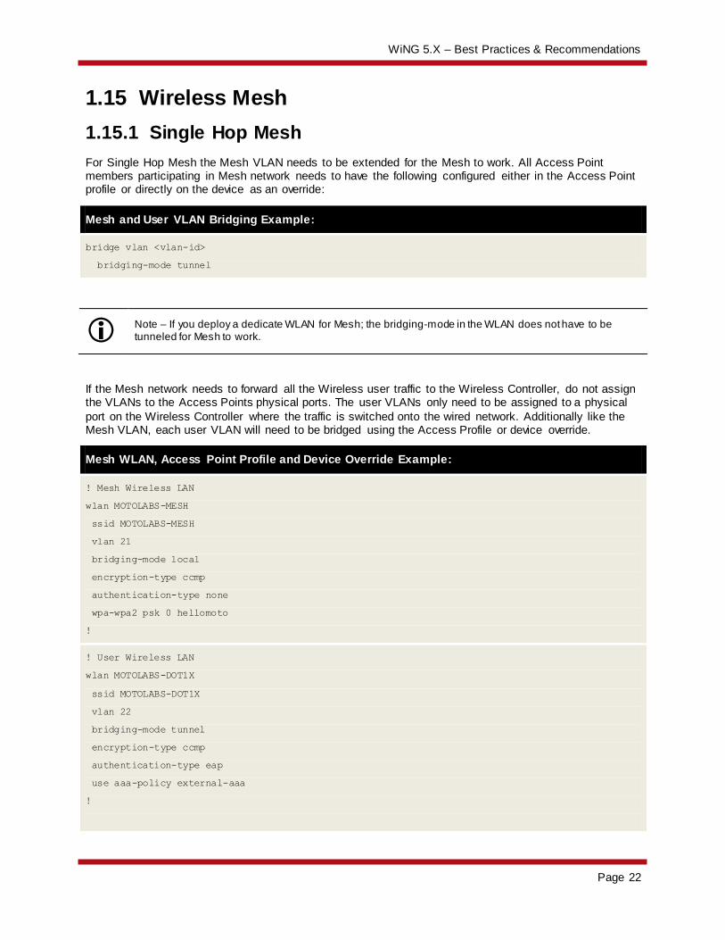
1.15.1 Single Hop Mesh
For Single Hop Mesh the Mesh VLAN needs to be extended for the Mesh to work. All Access Point members participating in Mesh network needs to have the following configured either in the Access Point profile or directly on the device as an override:
Mesh and User VLAN Bridging Example:
bridge vlan <vlan-id>
bridging-mode tunnel
Note – If you deploy a dedicate WLAN for Mesh; the bridging-mode in the WLAN does not have to be tunneled for Mesh to work.
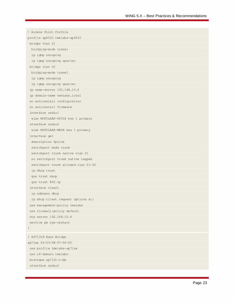
If the Mesh network needs to forward all the Wireless user traffic to the Wireless Controller, do not assign the VLANs to the Access Points physical ports. The user VLANs only need to be assigned to a physical
port on the Wireless Controller where the traffic is switched onto the wired network. Additionally like the Mesh VLAN, each user VLAN will need to be bridged using the Access Profile or device override.
Mesh WLAN, Access Point Profile and Device Override Example:
! Mesh Wireless LAN
wlan MOTOLABS-MESH
ssid MOTOLABS-MESH
vlan 21
bridging-mode local
encryption-type ccmp
authentication-type none
wpa-wpa2 psk 0 hellomoto
!
! User Wireless LAN
wlan MOTOLABS-DOT1X
ssid MOTOLABS-DOT1X
vlan 22
bridging-mode tunnel
encryption-type ccmp
authentication-type eap
use aaa-policy external-aaa
!
WiNG 5.X – Best Practices & Recommendations
Page 23
! Access Point Profile
profile ap6532 tmelabs-ap6532
bridge vlan 21
bridging-mode tunnel
ip igmp snooping
ip igmp snooping querier
bridge vlan 22
bridging-mode tunnel
ip igmp snooping
ip igmp snooping querier
ip name-server 192.168.10.6
ip domain-name tmelabs.local
no autoinstall configuration
no autoinstall firmware
interface radio1
wlan MOTOLABS-DOT1X bss 1 primary
interface radio2
wlan MOTOLABS-MESH bss 1 primary
interface ge1
description Uplink
switchport mode trunk
switchport trunk native vlan 21
no switchport trunk native tagged
switchport trunk allowed vlan 21-22
ip dhcp trust
qos trust dscp
qos trust 802.1p
interface vlan21
ip address dhcp
ip dhcp client request options all
use management-policy tmelabs
use firewall-policy default
ntp server 192.168.10.6
service pm sys-restart
!
! AP7131N Base Bridge
ap71xx 00-23-68-97-04-DC
use profile tmelabs-ap71xx
use rf-domain tmelabs
hostname ap7131-1-bb
interface radio2
WiNG 5.X – Best Practices & Recommendations
Page 24
channel 36+
power 1
mesh portal
mesh psk hellomoto
!
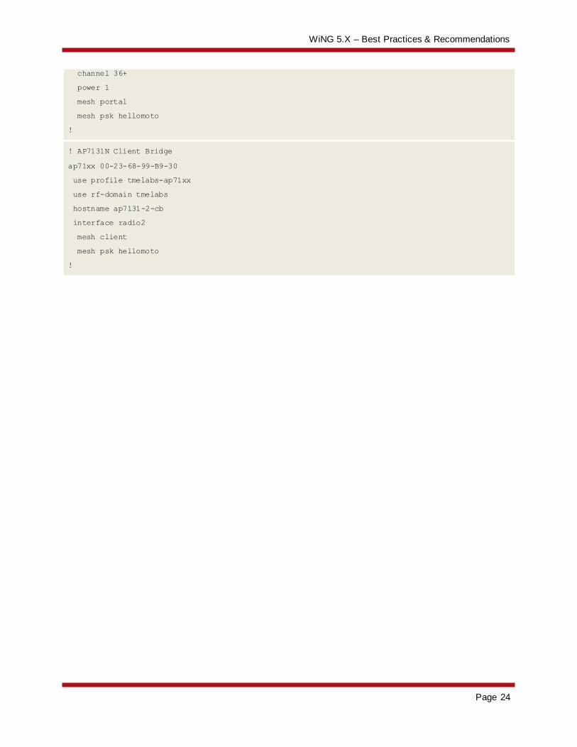
! AP7131N Client Bridge
ap71xx 00-23-68-99-B9-30
use profile tmelabs-ap71xx
use rf-domain tmelabs
hostname ap7131-2-cb
interface radio2
mesh client
mesh psk hellomoto
!
WiNG 5.X – Best Practices & Recommendations
Page 25
1.16 Virtual Controller
An Independent Access Point operating as a Virtual Controller only provides management / configuration functions and not data switching for other Independent Access Points.
An Independent Access Point operating as a Virtual Controller provides:
RF Management (Smart-RF)
Firmware Updates adopted Access Points
Configuration Management for adopted Access Points (24 Max)
Statistics Collection and Aggregation
Troubleshooting adopted Access Points.
No tunneled VLANs are supported. Additionally Independent Access Points operating as Virtual Controllers can only manage other Independent Access Points of the same model. For example an AP
7131 Independent Access Point can only manage other AP 7131 Independent Access Points and not AP 6511, AP 6521, AP 6532, AP 7161 or AP 7181 Independent Access Points.
1.17 Switched Virtual Interfaces
When a Wireless Controller or Access Point bridges traffic on a VLAN it does not require a Switched Virtual Interface to be defined. One common mistake is to create a Virtual Interface for locally bridged VLANs on a device when it’s not required. A Virtual Interface is only required for the following scenarios:
1. Layer 3 Access Point adoption.
2. Device Management.
3. When the Wireless Controller or Access Point is providing IPv4 routing services between multiple
IPv4 interfaces.
4. When the Wireless Controller or Access Point is providing NAT.
5. When the Wireless Controller or Access Point is terminating IPsec VPN tunnels.
6. When DHCP services are running on the Wireless Controller or Access Point.
Please note that all routed IPv4 traffic is inspected by the stateful packet inspection firewall. When IPv4 routing doesn’t work as expected with the defined Virtual IP interfaces, issue a service pktcap on drop
command to see if any packets are being dropped by the stateful packet inspection firewall. Most firewall checks are enabled by default and can be disabled if needed.
WiNG 5.X – Best Practices & Recommendations
Page 26
1.18 Zero Config IPv4 Address
A Zero Config IPv4 address is assigned by default to new Access Points on VLAN 1 to provide a mechanism to configure the Access Points when no DHCP services are present on the network. It’s
important to note that the Zero Config IPv4 address will only apply to VLAN 1 and will not work on any other VLAN.
If no DHCP services are present, each Access Point will be automatically configured with a Zero Config
IPv4 Address 169.254.X.Y/16 where:
1. X = the decimal equivalent of the 5th octet of the MAC address
2. Y = the decimal equivalent of the 6th octet of the MAC address
The Zero Config IPv4 address for an Access Point can be determined by converting the 5th
and 6th
octets of the Access Points MAC address from HEX to Decimal. For example an Access Point with the MAC address 00-23-68-97-04-DC will use the Zero Config IPv4 Address 169.254.4.220.
1.19 Firmware Upgrades
1.19.1.1 Centrally Managed Environments
When upgrading Access Points in large centrally managed distributed environments, it is recommended that the ap-upgrade command be utilized to perform the upgrade. By default after a Controller is upgraded to a new release, the remote Access Points will individually download their new firmware upon
re-adoption. The maximum number of simultaneous upgrades a Controller can support is 20.
To optimize WAN bandwidth and streamline the upgrade process for large centrally managed deployments it is recommended that:
1. Automatic AP upgrades be disabled on the Controller profile prior to reloading the Controllers with the new firmware release.
2. The ap-upgrade command be utilized to initiate the upgrade via the elected RF Domain
Managers at each remote site.
Using this methodology allows up to 20 x remote sites to be simultaneously upgraded vs. 20 x individual Access Points.
1.19.2 Slow WAN Links
When performing manual firmware upgrades over slow WAN links, it is recommended that you increase the idle-sessions-timeout parameter in the management policy to a higher value. By default the idle timeout value is set to 30 minutes and the telnet, SSH or HTTP(s) session may timeout if the manual
firmware upgrade exceeds 30 minutes. Increasing this value allows the management session to be maintained for longer periods allowing the a manual firmware upgrade to be completed.
Increasing the Idle Session Timeout Interval Example:
RFSX000(config-management-policy-<name># idle-session-timeout <value>
Please note that this parameter will only be applied to new telnet, SSH or HTTP(s) management sessions. Once this value is changed you will need to close your existing management session and
restart a new management session.

WiNG 5.X – Best Practices & Recommendations
Page 27
WiNG 5.X – Best Practices & Recommendations
Page 28