wintergard wet roof & gutter de-icing · appendix b. wintergard wet system limited warranty...
TRANSCRIPT

ii / ii THERMAL MANAGEMENT SOLUTIONS EN-RaychemWinterGard-DG-H56804 10/13
Wintergard Wet roof & gutter de-icingdesign, installation and maintenance guide
THERMAL bUILdING SOLUTIONS WWW.PENTAIRTHERMAL.COM

THERMAL buiLding SOLuTiOnSEN-RaychemWinterGard-DG-H56804 10/15i
WinterGard Wet SyStem deSiGn, inStallation and maintenance Guide
• Interior Structural damage – Ice dams on roof edges lead to water ingress. • Exterior damage to Gutters – Frozen gutters are heavy, leading to distortion or breakage.• Falling Icicles – Icicles pose a threat and a liability to people and property.• Slippery Walkways – Overfilled gutters allow water to fall on the ground and refreeze.
A WinterGard Wet self-regulating heating cable system eliminates icicles and ice dams safely and efficiently. A professional-quality electric heating cable, WinterGard Wet heat-ing cable can be cut and spliced to fit the layout of any roof line. Installed on a roof or inside gutters and downspouts, WinterGard Wet heating cable creates a drainage path for melting snow, adjusting its heat output as the ambient temperature fluctuates. When the gutter is dry, the system automatically cuts back its power output so it won’t ever over-heat or burn out.
WINTERGARd WET
Simple and Reliable
• Can be overlapped• Can be cut to length• Will not burn out• Saves energy• Will not overheat roofing materials or plastic gutters
The ProblemRooftop snow, melted in sunlight or from the building’s interior heat, trickles down to the cold roof edge and freezes again, forming ice dams and icicles—creating four potential hazards.
One Simple Solution
• The H908 Plug-in cord set reduces installa-tion costs by utilizing an existing power outlet, eliminating the need to hardwire. The H908 also includes a 27-mA ground-fault equip-ment protection device, required by the National Electrical Code.
• Reduce the amount of heating cable required by tracing only problem areas such as the roof edge above a walkway or the north side of a building.
• Trace only the gutters and downspouts. It is not always necessary to serpentine heat-ing cables on the roof eave. If ice dams are not located on the eave, installing heating cables only in the gutters and downspouts may be sufficient.
Temperature
Self-regulatingpower output
Heating Cable ConstructionNickel-copper bus wires
Self-regulating conductive coreInsulating jacket
Tinned-copper braid
Outer polyolefin jacket
Parallel CircuitryCurrent flows between the two bus wires independently at each point along the heating cable.
Self-RegulationThe conductive polymer heating core regulates its power output in response to the temperature.

ii THERMAL buiLding SOLuTiOnS EN-RaychemWinterGard-DG-H56804 10/15
CONTENTS
Introduction . . . . . . . . . . . . . . . . . . . . . . . . . . . . . . . . . . . . . . . . . . . . . . . . . . . . 1Overview . . . . . . . . . . . . . . . . . . . . . . . . . . . . . . . . . . . . . . . . . . . . . . . . . . . . . . . . . . 1Safety Guidelines . . . . . . . . . . . . . . . . . . . . . . . . . . . . . . . . . . . . . . . . . . . . . . . . . . . 1Codes and Approvals . . . . . . . . . . . . . . . . . . . . . . . . . . . . . . . . . . . . . . . . . . . . . . . . 1WinterGard Wet System Description . . . . . . . . . . . . . . . . . . . . . . . . . . . . . . . . . . . . 2
design Guidelines . . . . . . . . . . . . . . . . . . . . . . . . . . . . . . . . . . . . . . . . . . . . . . . 3How to Use These Guidelines . . . . . . . . . . . . . . . . . . . . . . . . . . . . . . . . . . . . . . . . . 3Step 1. Heating Cable Layout . . . . . . . . . . . . . . . . . . . . . . . . . . . . . . . . . . . . . . . . . . 3
Layout Overview . . . . . . . . . . . . . . . . . . . . . . . . . . . . . . . . . . . . . . . . . . . . . . . . . . 3Sloped Roof—Shingle Roof . . . . . . . . . . . . . . . . . . . . . . . . . . . . . . . . . . . . . . . . . 4
Other Considerations . . . . . . . . . . . . . . . . . . . . . . . . . . . . . . . . . . . . . . . . . . . 4Sloped Roof—Standing Seam–Metal. . . . . . . . . . . . . . . . . . . . . . . . . . . . . . . . . . 5
Other Considerations . . . . . . . . . . . . . . . . . . . . . . . . . . . . . . . . . . . . . . . . . . . 6Flat Roof . . . . . . . . . . . . . . . . . . . . . . . . . . . . . . . . . . . . . . . . . . . . . . . . . . . . . . . . 6Sloped Roof Without Gutters . . . . . . . . . . . . . . . . . . . . . . . . . . . . . . . . . . . . . . . . 7
Other Considerations . . . . . . . . . . . . . . . . . . . . . . . . . . . . . . . . . . . . . . . . . . . 7Valleys . . . . . . . . . . . . . . . . . . . . . . . . . . . . . . . . . . . . . . . . . . . . . . . . . . . . . . . . . . 8Roof/Wall Intersections . . . . . . . . . . . . . . . . . . . . . . . . . . . . . . . . . . . . . . . . . . . . 8Gutters. . . . . . . . . . . . . . . . . . . . . . . . . . . . . . . . . . . . . . . . . . . . . . . . . . . . . . . . . . 9Downspouts . . . . . . . . . . . . . . . . . . . . . . . . . . . . . . . . . . . . . . . . . . . . . . . . . . . . 10
Step 2. Attachment Methods . . . . . . . . . . . . . . . . . . . . . . . . . . . . . . . . . . . . . . . . . 11Roof Attachment Methods . . . . . . . . . . . . . . . . . . . . . . . . . . . . . . . . . . . . . . . . . 12
Mechanical Attachment of Clips . . . . . . . . . . . . . . . . . . . . . . . . . . . . . . . . . 12Adhesive Attachment of Clips. . . . . . . . . . . . . . . . . . . . . . . . . . . . . . . . . . . . 13Alternative Attachment Methods . . . . . . . . . . . . . . . . . . . . . . . . . . . . . . . . . 13Belt Loop Approach. . . . . . . . . . . . . . . . . . . . . . . . . . . . . . . . . . . . . . . . . . . . 14
Attachment Methods for Other Areas . . . . . . . . . . . . . . . . . . . . . . . . . . . . . . . . 15Gutters . . . . . . . . . . . . . . . . . . . . . . . . . . . . . . . . . . . . . . . . . . . . . . . . . . . . . . 15Downspouts . . . . . . . . . . . . . . . . . . . . . . . . . . . . . . . . . . . . . . . . . . . . . . . . . . 15Drip Loops . . . . . . . . . . . . . . . . . . . . . . . . . . . . . . . . . . . . . . . . . . . . . . . . . . . 15
Step 3. Control . . . . . . . . . . . . . . . . . . . . . . . . . . . . . . . . . . . . . . . . . . . . . . . . . . . . 16Controller Specifications . . . . . . . . . . . . . . . . . . . . . . . . . . . . . . . . . . . . . . . . . . 16
Manual Control . . . . . . . . . . . . . . . . . . . . . . . . . . . . . . . . . . . . . . . . . . . . . . . 16Typical Wiring Schematic . . . . . . . . . . . . . . . . . . . . . . . . . . . . . . . . . . . . . . . 16Ambient Thermostats . . . . . . . . . . . . . . . . . . . . . . . . . . . . . . . . . . . . . . . . . . 16Automatic Controllers . . . . . . . . . . . . . . . . . . . . . . . . . . . . . . . . . . . . . . . . . . 17Typical Wiring Schematic . . . . . . . . . . . . . . . . . . . . . . . . . . . . . . . . . . . . . . . 17 Snow Sensors . . . . . . . . . . . . . . . . . . . . . . . . . . . . . . . . . . . . . . . . . . . . . . . . 18
Step 4. Accessory Selection . . . . . . . . . . . . . . . . . . . . . . . . . . . . . . . . . . . . . . . . . . 18Step 5. Electrical Design . . . . . . . . . . . . . . . . . . . . . . . . . . . . . . . . . . . . . . . . . . . . 20
Determining the Number of Circuits. . . . . . . . . . . . . . . . . . . . . . . . . . . . . . . . . 20
Installation Guidelines . . . . . . . . . . . . . . . . . . . . . . . . . . . . . . . . . . . . . . . . . . 22Heating Cable Installation . . . . . . . . . . . . . . . . . . . . . . . . . . . . . . . . . . . . . . . . . . . 22Heating Cable Damage . . . . . . . . . . . . . . . . . . . . . . . . . . . . . . . . . . . . . . . . . . . . . . 22Heating Cable Handling . . . . . . . . . . . . . . . . . . . . . . . . . . . . . . . . . . . . . . . . . . . . . 23Power Connection, Splice, and Tee Installation . . . . . . . . . . . . . . . . . . . . . . . . . . 23Controls and Feed Wiring . . . . . . . . . . . . . . . . . . . . . . . . . . . . . . . . . . . . . . . . . . . . 23
When installing controls and feed wiring . . . . . . . . . . . . . . . . . . . . . . . . . . . . . 23Test Methods . . . . . . . . . . . . . . . . . . . . . . . . . . . . . . . . . . . . . . . . . . . . . . . . . . . . . . 24
Insulation Resistance (Megohmmeter) Test. . . . . . . . . . . . . . . . . . . . . . . . . . . 23Procedure. . . . . . . . . . . . . . . . . . . . . . . . . . . . . . . . . . . . . . . . . . . . . . . . . . . . 24Insulation Resistance Criteria . . . . . . . . . . . . . . . . . . . . . . . . . . . . . . . . . . . 24Continuity Test . . . . . . . . . . . . . . . . . . . . . . . . . . . . . . . . . . . . . . . . . . . . . . . . 25
Operation and Maintenance . . . . . . . . . . . . . . . . . . . . . . . . . . . . . . . . . . . . . . 26System Start-up and Operation . . . . . . . . . . . . . . . . . . . . . . . . . . . . . . . . . . . . . . . 26
Prior to system start-up. . . . . . . . . . . . . . . . . . . . . . . . . . . . . . . . . . . . . . . . . . . 26Indication of operation . . . . . . . . . . . . . . . . . . . . . . . . . . . . . . . . . . . . . . . . . . . . 26
Periodic Inspection/Maintenance . . . . . . . . . . . . . . . . . . . . . . . . . . . . . . . . . . . . . 26Roof/Gutter Repair and Maintenance . . . . . . . . . . . . . . . . . . . . . . . . . . . . . . . . . . 26

THERMAL buiLding SOLuTiOnSEN-RaychemWinterGard-DG-H56804 10/15iii
WinterGard Wet SyStem deSiGn, inStallation and maintenance Guide
Troubleshooting . . . . . . . . . . . . . . . . . . . . . . . . . . . . . . . . . . . . . . . . . . . . . . . . 27Appendix A. WinterGard Wet Heating Cables data Sheet . . . . . . . . . . . . . . 29Appendix b. WinterGard Wet System Limited Warranty . . . . . . . . . . . . . . 30design Worksheet . . . . . . . . . . . . . . . . . . . . . . . . . . . . . . . . . . . . . . . . . . . . . . 31

1 / 35
Introduction
THERMAL buiLding SOLuTiOnS EN-RaychemWinterGard-DG-H56804 10/15
INTROdUCTION
Overview
WinterGard Wet heating cable is a professional-grade, self-regulating electrical cable that can be used for roof and gutter de-icing. This guide provides complete design and installation instructions for a WinterGard Wet system that will provide drain paths for the following applications:
• Roofs made from all types of standard roofing materials, including shake, shingle, rubber, tar, wood, metal, and plastic.
• Gutters made from standard materials, including metal, plastic, and wood.
• Downspouts made from standard materials, including metal and plastic.
The guide does not provide information for using a WinterGard Wet system for the following applications:
• Preventing snow movement on roofs—WinterGard Wet cable will not keep snow or ice from falling off the roof. Snow fences or snow guards should be used to elimi-nate snow movement.
For the names of manufacturers of snow guards or snow fences, contact Pentair's Thermal Building Solutions at (800) 545-6258.
• Clear accumulated snow off a roof and/or reduction of snow load—WinterGard Wet cable is designed to provide a continuous path for melt water, not to clear accumu-lated snow.
If your application conditions are different, or if you have any questions, contact Pentair's Thermal Building Solutions at (800) 545-6258.
The roof and gutter de-icing systems covered in this guide are for normal winter conditions. For extreme winter conditions with snow fall accumulations of 9 inches or more and ambient temperatures below 0°F contact Pentair's Thermal Building Solutions at (800) 545-6258.
Safety Guidelines
The safety and reliability of any heat-tracing system depends on the quality of the products selected and the manner in which they are installed and maintained. Incorrect design, handling, installation, or maintenance of any of the system components could damage the de-icing system or the roof and may result in inadequate de-icing, electric shock, or fire. To minimize these risks and to ensure that the system performs reliably, read and carefully follow the information, warnings, and instructions in this guide.
This symbol identifies particularly important safety warnings that must be followed.
Codes and Approvals
Installation of a WinterGard Wet system is governed by Article 426 of the National Electrical Code (NEC) and Part I, Clause 62-300, of the Canadian Electrical Code (CEC). Pentair's Thermal Building Solutions, the NEC, and the CEC all require the use of ground-fault protection of equipment to reduce the risk of fire caused by damage or improper installation. All installations must also comply with applicable local codes and standards.
The WinterGard Wet roof and gutter de-icing system is UL Listed and CSA Certified for use in nonhazardous areas, and specifically for roof and gutter de-icing.

2 / 35
WinterGard Wet SyStem deSiGn, inStallation and maintenance Guide
THERMAL buiLding SOLuTiOnSen-raychemWinterGard-dG-H56804 10/15
WinterGard Wet System description
Ice dams can cause water ingress into buildings and generate dangerous icicles. A WinterGard Wet system can help prevent ice dams and icicles by maintaining a continuous path for melt water to drain from the roof. As long as a heated path from the roof to a safe discharge area is maintained, ice dams will not form. The WinterGard Wet system can be used on roofs and valleys and in downspouts and gutters made from all types of standard roofing materials, including metal, plastic, wood, shake/shingle, rubber, and tar.
The WinterGard Wet system is intended to provide drain paths. A typical system includes the following:
Downspout Hanger Kit
H915
Heating Cable
H622 (208 V – 240 V)H612 (120 V)
Splice/Tee Kit
H910
Attachment Clip
H913 10/pkgH914 50/pkg
H912
End Seal
(Included with power connection kit or sold separately)
Power Connection Kits
H908
H900
Text text text
text text text text
text text text text
text text
Automatic Controller
GF-ProPD-Pro
3 / 35
Design Guidelines
THERMAL buiLding SOLuTiOnS EN-RaychemWinterGard-DG-H56804 10/15
dESIGN GUIdELINES
How to Use These Guidelines
When using the WinterGard Wet Design and Installation Guide, follow these steps:
1. Determine the cable layout for the roof, gutters, and downspouts–Step 1 below.
2. Determine the attachment methods you will use – “Step 2. Attachment Methods” on page 11.
3. Select the type of control you will use – “Step 3. Control” on page 16.
4. Select accessories – “Step 4. Accessory Selection” on page 18.
5. Determine electrical requirements – “Step 5. Electrical Design” on page 20.
After you have reviewed this guide, use the “Design Worksheet” on page 31 to complete the design of your project.
Step 1. Heating Cable Layout
LAyOUT OvERvIEW
Heating cable layout depends primarily on the roof type. The following sections show typical layouts on standard roof types.
Roof type/area Page
Sloped Roof—Shingle Roof 4
Sloped Roof—Standing Seam–Metal 5
Flat Roof 6
Sloped Roof Without Gutters 7
Valleys 8
Roof/Wall Intersections 8
Gutters 9
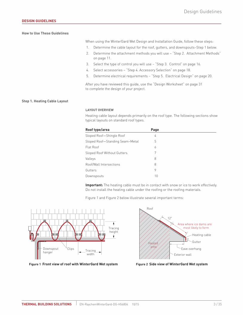
Downspouts 10 Important: The heating cable must be in contact with snow or ice to work effectively. Do not install the heating cable under the roofing or the roofing materials.
Figure 1 and Figure 2 below illustrate several important terms:
Tracingheight
12"
Area where ice dams are most likely to form
Eave overhang
Exterior wall
Heating cable
Gutter
Roof
Heated areaClipsDownspout
hanger Tracingwidth
Figure 1 Front view of roof with WinterGard Wet system Figure 2 Side view of WinterGard Wet system

4 / 35
WinterGard Wet SyStem deSiGn, inStallation and maintenance Guide
THERMAL buiLding SOLuTiOnSen-raychemWinterGard-dG-H56804 10/15
SLOPEd ROOF—SHINGLE ROOF
For sloped roofs, ice dams may form at the roof edge. To maintain a continuous path for melt water runoff, route the heating cable in a serpentine pattern as shown in Figure 3 below and follow the appropriate attachment recommendations in Step 2. Additional heating cable may be needed for other gutters, downspouts, and valleys.
2'
UV-resistant cable tie
Figure 3 Layout in a serpentine pattern
Note: Attachment methods are purposely not shown in Figure 3. For attachment methods, proceed to “Step 2. Attachment Methods” on page 11.
• Run heating cable up the roof until it is approximately 12 inches past the exterior wall into the heated area (see Figure 2 on page 3).
• Install the heating cable on the roof in a serpentine pattern as shown in the illustra-tion above.
• Add 6 inches of heating cable for each foot of roof edge to extend the heating cable on the roof all the way down to meet with the run of heating cable in the gutter. This will ensure that you have a continuous path where the melted water can flow. Attach the heating cables together with UV-resistant cable ties.
• For gutter deeper than four inches, additional cable will be needed, contact Pen-tair's Thermal Building Solutions at (800) 545-6258.
TAbLE 1 WINTERGARd WET HEATING CAbLE LENGTH FOR ROOF dE-ICING
Eave overhang1 distance
Tracing2 width
Tracing2 height
Length of heating cable (per foot of roof edge)
None 2 ft 12 in 2 ft
12 in 2 ft 24 in 2.8 ft
24 in 2 ft 36 in 3.8 ft
36 in 2 ft 48 in 4.8 ft1. See Figure 22. See Figure 1
Other Considerations
• Use a snow fence or snow guards (not shown) to prevent snow from sliding. Do not extend the heating cable above the snow fence.
• It is not always necessary to run heating cables on the roof. If you do not experience ice dams on the roof, installing heating cables only in the gutters and downspouts may be sufficient.

5 / 35
Design Guidelines
THERMAL buiLding SOLuTiOnS EN-RaychemWinterGard-DG-H56804 10/15
SLOPEd ROOF—STANdING SEAM–METAL
For sloped standing-seam metal roofs, ice dams may form at the roof edge. To maintain a continuous path for melt water to run off, route the heating cable along the seams as shown in Figure 4 and follow the attachment recommendations in Step 2. Additional heating cable may be needed for downspouts and valleys.
Tracingheight
Standing seam width
Gutter depth
Figure 4 Layout on a standing seam roof
Note: Attachment methods are purposely not shown in Figure 4. For attachment methods, proceed to “Step 2. Attachment Methods” on page 11.
• Run the heating cable up the seam until it is approximately 12 inches past the exte-rior wall and over a heated area (see Figure 2 on page 3).
• Run the heating cable up one side of the seam, loop it over to the other side, and return it to the bottom of the gutter. Continue along the bottom of the gutter to the third seam and repeat the process (see Figure 4). If the metal roof panels are more than 24 inches wide, trace every seam along the roof edge.
• Add 6 inches of heating cable for each foot of roof edge to extend the heating cable on the roof all the way down to meet with the run of heating cable in the gutter. This will ensure that you have a continuous path where the melted water can flow. Attach the heating cables together with UV-resistant cable ties.
Note: For large commercial building with standing seam roofs contact Pentair's Thermal Building Solutions at (800) 545-6258.
TAbLE 2 WINTERGARd WET HEATING CAbLE LENGTH FOR STANdING SEAM ROOFS
Eave overhang distance
Standing seam width
Tracing height
Length of heating cable (per foot of roof edge)
0 in 18 in 12 in 2.5 ft12 in 18 in 24 in 2.8 ft24 in 18 in 36 in 3.6 ft36 in 18 in 48 in 4.3 ft0 in 24 in 12 in 2.0 ft12 in 24 in 24 in 2.4 ft24 in 24 in 36 in 2.9 ft36 in 24 in 48 in 3.6 ft• On a metal seamed roof system, the length of heating cable needed for the roof and
gutter can be determined by the formula: Heating cable length (ft) = [2 x (tracing height (inches) + gutter depth (inches)/12)] x no. of seams traced + distance along the gutter/roof edge (ft)
Additional heating cable will be needed for accessory connections and downspouts.

6 / 35
WinterGard Wet SyStem deSiGn, inStallation and maintenance Guide
THERMAL buiLding SOLuTiOnSen-raychemWinterGard-dG-H56804 10/15
Other Considerations• Use a snow fence or snow guards (not shown) to prevent snow from sliding. Do not
extend the heating cable above the snow fence.• If the roofing materials continue down the fascia, add enough to the heating cable
length to allow for this.
• It is not always necessary to run heating cables on the roof. If you do not experience ice dams on the roof or roof damage, installing heating cables only in the gutters and down-spouts may be sufficient.
FLAT ROOF
Ice dams may occur on flat roofs at the edge flashing and at drains. Flat roofs are typically pitched toward drains and these paths often become obstructed by snow and ice. To maintain a continuous path for melt water to run off, route the heating cable as shown in Figure 5 and follow the appropriate attachment recommendations in Step 2. Additional heating cable may be needed for downspouts.
Note: For commercial buildings with large flat roofs contact Pentair's Thermal Building Solutions at (800) 545-6258.
Junctionbox
DrainSlope
Ice can form around drain and at roof edges where adjacent snow thaws during the day and refreezes at night.
Heating cable provides a continuous heated path to allow melt water to run off the roof before it refreezes.
Heating cable should be positioned around the perimeter and in the valleys of a flat roof. The heating cable must extend into the drain orscupper to allow the melt water to exit the roof.
Scupper
Drip loop
Heating cable end seal
Figure 5 Layout on a flat roof
7 / 35
Design Guidelines
THERMAL buiLding SOLuTiOnS EN-RaychemWinterGard-DG-H56804 10/15
• Place heating cable around perimeter.
• Trace valleys from perimeter to drain.
• Extend heating cable into internal downspouts at least 12 inches into heated space.
• External downspouts and scuppers must be treated carefully. A path must be pro-vided for the valley/perimeter heating cable to the point of discharge (see Figure 11 on page 10).
• To avoid damage, do not walk on the heating cable.
• For attachment methods, proceed to “Step 2. Attachment Methods” on page 11.
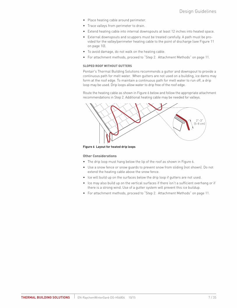
SLOPEd ROOF WITHOUT GUTTERS
Pentair's Thermal Building Solutions recommends a gutter and downspout to provide a continuous path for melt water. When gutters are not used on a building, ice dams may form at the roof edge. To maintain a continuous path for melt water to run off, a drip loop may be used. Drip loops allow water to drip free of the roof edge.
Route the heating cable as shown in Figure 6 below and follow the appropriate attachment recommendations in Step 2. Additional heating cable may be needed for valleys.
2"–3"(5–8 cm)
Figure 6 Layout for heated drip loops
Other Considerations
• The drip loop must hang below the lip of the roof as shown in Figure 6.
• Use a snow fence or snow guards to prevent snow from sliding (not shown). Do not extend the heating cable above the snow fence.
• Ice will build up on the surfaces below the drip loop if gutters are not used.
• Ice may also build up on the vertical surfaces if there isn’t a sufficient overhang or if there is a strong wind. Use of a gutter system will prevent this ice buildup.
• For attachment methods, proceed to “Step 2. Attachment Methods” on page 11.

8 / 35
WinterGard Wet SyStem deSiGn, inStallation and maintenance Guide
THERMAL buiLding SOLuTiOnSen-raychemWinterGard-dG-H56804 10/15
vALLEyS
Ice dams may form at the valley on a roof where two different slopes meet. To maintain a continuous path for melt water, run the heating cable up and down the valley as shown in Figure 7 and follow the appropriate attachment recommendations in Step 2. Additional heating cable may be needed for the roof surface, gutters, and downspouts.
2/3
1/3
Figure 7 Layout for a valley
• Trace two-thirds of the way up each valley with a double run of heating cable (loop up and back once).
• The heating cable must extend into the gutter. If you don’t have gutters, the heating cable should extend over the edge 2 to 3 inches to form a drip loop.
• For attachment methods, proceed to “Step 2. Attachment Methods” on page 11.
ROOF/WALL INTERSECTIONS
Roof/wall intersections can be treated in the same manner as valleys. Snow has a tendency to collect at this interface. Providing a loop of heating cable two-thirds of the way up the slope will provide a path for the extra melt water in this area to escape.
2"–3"
4"–6"
1/3
2/3
Figure 8 Layout for a roof/wall intersection
• Extend a loop of heating cable two-thirds of the way up the slope adjacent to the wall.
• Position the closest heating cable approximately 2 to 3 inches from the wall. Posi-tion the second heating cable 4 to 6 inches from the first.
• For attachment methods, see “Step 2. Attachment Methods” on page 11.

9 / 35
Design Guidelines
THERMAL buiLding SOLuTiOnS EN-RaychemWinterGard-DG-H56804 10/15
GUTTERS
Ice may accumulate in gutters and at the roof edge. To maintain a continuous path for melt water to run off, route the heating cable as shown in Figure 9 below. Additional heating cable may be needed for the roof surface, downspouts, and valleys.
Figure 9 Layout in standard gutters
• Use one run of heating cable in the gutter.
• For gutters 5–6 inches wide, use two runs of heating cable. For gutter wider than 6 inches contact Pentair's Thermal Building Solutions at (800) 545-6258.
• No attachment to gutter is normally required. If attachment is desired, use a roof clip such as a H913 or H914 clip.
• Continue heating cable down the inside of the downspout. See “Downspouts” on page 10 for more information.

10 / 35
WinterGard Wet SyStem deSiGn, inStallation and maintenance Guide
THERMAL buiLding SOLuTiOnSen-raychemWinterGard-dG-H56804 10/15
dOWNSPOUTS
Ice may form in downspouts and prevent melt water from escaping from the roof. To maintain a continuous path for melt water to run off, run the heating cable inside the downspout to the end as shown in Figure 10 and Figure 11 below. Follow the appropriate attachment recommendations in Step 2. Additional heating cable may be needed for the roof surface, gutters, and valleys.
Figure 10 Heating cable at top of downspout
Drain removes melt waterbelow the frost line.
Accumulated icemay block drains.
Accumulated icecan be removed.
12"
Figure 11 Heating cable at bottom of downspout
• If the downspout ends underground, the heating cable should extend into a heated area or below the frost line.
• For low-water-flow situations, teeing the heating cable so that a single run goes down the downspout is usually sufficient. For high-water-flow situations, where ambient temperatures often fall below 0°F (–18°C), or where it isn’t convenient to tee the heating cable, use two runs—by running the heating cable down to the bot-tom and then back to the top.
• For downspouts that end at grade, leave a small drip loop (no more than one inch of cable exposed) at the bottom of the downspout.
• If a single run of heating cable is used, the end seal should be looped back up at least 12 inches inside the downspout to prevent mechanical damage to the cable or end seal.
• If the downspout ends near the ground, water will refreeze on the ground and build up around the downspout, eventually blocking the opening.
WARNING: To prevent mechanical damage, do not leave the end seal exposed at the end of the downspout. Loop it back up the downspout at least 12 inches.
Note: WinterGard Wet cannot be installed inside any storm drains, or in downspout drains where oil or grease may be present.

11 / 35
Design Guidelines
THERMAL buiLding SOLuTiOnS EN-RaychemWinterGard-DG-H56804 10/15
Step 2. Attachment Methods
Heating cable attachment methods depend primarily upon the roof type. The following table shows the recommended attachment methods for typical roof materials and roof areas.
TAbLE 3 ATTACHMENT METHOdS FOR TyPICAL ROOFS
Roof materialRecommended attachment method
Alternate attachment method
Shake/shingle Mechanical clips (page 12)
Rubber/membrane Belt loop (page 14)
Metal Mechanical clips (page 12) Adhesive clips (page 13)* Belt loop (page 14)
Wood Mechanical clips (page 12)
Other Alternative (page 13)
Area
Attachment method
Gutters Attachment generally not required (page 15)
Downspouts Downspout hangers (page 15)
Accessory locations Drip loops (page 15)
Roof edges with no gutter
Drip loops (page 15)
Note: Do not use adhesives on slate or tile roofs. Please contact roofing manufacturer for a recommended attachment method or contact your Pentair's Thermal Building Solutions representative.
* Before using adhesives on metal roofs check with the roofing manufacturer.
TAbLE 4 AdHESIvE
Adhesive description ColorApproximate tooling time
Curing time
dispensing equipment
Momentive Performance Materials, Inc RTV167
Neutral-cure silicone adhesive
Gray 20 minutes 48 hours Caulking gun
SpeedBonder®
H3300Methacrylate adhesive
Tan 15 minutes 24 hours 2 part mixing dispenser
SpeedBonder H4800
Methacrylate adhesive
Light yellow
45 minutes 24 hours 2 part mixing dispenser
Plexus® MA300 Methacrylate adhesive
Yellow 15 minutes 16 hours 2 part mixing dispenser
Plexus MA310 Methacrylate adhesive
Yellow 30 minutes 16 hours 2 part mixing dispenser
Adhesive is not supplied by Pentair's Thermal Building Solutions. RTV 167 Silicone Adhesive is a neutral-cure silicone adhesive. Contact: Momentive Performance Materials, Inc. at (800) 332-3390 for the name of a distributor. Follow manufacturer’s instructions for surface preparation and installation.

12 / 35
WinterGard Wet SyStem deSiGn, inStallation and maintenance Guide
THERMAL buiLding SOLuTiOnSen-raychemWinterGard-dG-H56804 10/15
ROOF ATTACHMENT METHOdS
Mechanical Attachment of Clips
One of the most common attachment methods is to use H913 or H914 roof clips. It can be used on all surfaces that can be nailed or screwed into. The H913 is a package of 10 clips. The H914 is a bulk package of 50 clips.
Figure 12 H913/H914 clip attachment
• The roof clips are used to secure WinterGard Wet heating cable. This multipurpose bracket attaches with a screw or nail to many types of roofs and gutters.
• After determining the heating cable layout, fasten the clips to the roof before in-stalling the heating cable in the bracket. Apply sufficient water-sealing material around the clips and nails or screws to prevent roof leaks.
• Thread the heating cable into the clips. Use additional clips wherever the heating cable may be subject to abrasion from movement.
• Use pliers to close the clamps, but be careful not to crush the heating cable.
• The H913 kit is sufficient to attach the heating cable on 7 feet of roof edge. The H914 bulk package of 50 clips is sufficient to attach the heating cable on 35 feet of roof edge using a serpentine layout. Your layout may require additional clips.
• For layouts other than the standard serpentine, use one clip for each 5 to 10 feet of un-supported heating cable and at every change of heating cable direction.
• For shingled roofs, the loops of heating cable being serpentined on the roof should be attached, using a UV-resistant cable tie, to the heating cable run in the gutter.
• For standing-seam roofs, the heating cable should be cable-tied together at the bot-tom of the seam.

13 / 35
Design Guidelines
THERMAL buiLding SOLuTiOnS EN-RaychemWinterGard-DG-H56804 10/15
Adhesive Attachment of Clips
For roofs where penetrating attachments are not desired, use the H913/H914 clip attached by adhesive.
Figure 13 H913/H914 clip on standing seam roof
• The H913/H914 roof clips are used to secure WinterGard Wet heating cable. The clip attaches with adhesive (not supplied by Pentair's Thermal Building Solutions) to many types of roofs and gutters.
• See Table 4 on page 11 for a recommended adhesive, or contact Pentair's Thermal Building Solutions for alternatives.
• On a standing seam roof, use four clips on each seam being traced. On a flat sur-face, use one clip for every 5 to 10 feet of unsupported heating cable and at every heating cable change of direction.
• Follow all recommendations from the adhesive manufacturer with regard to clean-ing and preparing the roof surface for the adhesive.
• After determining the heating cable layout, fasten the clips to the roof with the ad-hesive and allow the adhesive to cure before installing the heating cable.
• After the adhesive has cured, thread the heating cable through the clips. Use addi-tional clips wherever the heating cable may be subject to abrasion from movement.
Note: How well the adhesive holds can be strongly affected by how well the surface to which it will adhere is prepared and by what type of adhesive is used. Be sure to follow the recommendations of the adhesive manufacturer.
Note: Before using adhesives on metal roofs check with the roofing manufacturer.
Alternative Attachment Methods
The H913 and H914 attachment clips were developed as an easy way to provide enough support for the heating cable without crimping, crushing, or otherwise damaging the heating cable and without applying any chemicals or adhesives directly to the heating cable. Other means may be used to attach the heating cable as long as they:
• Do not crush, crimp, cut, or otherwise damage the heating cable. Damage to the heating cable could cause the system to fail, resulting in electric shock or fire.
• Do not apply adhesives or other chemicals directly to the heating cable. Many adhesives will not stick to the outer jacket, which could cause the attachment method to fail and could result in inadequate de-icing.
• Provide enough strength to support the heating cable on the roof and any load from snow that collects on the system. If the attachment method is not strong enough, the heating cable could come loose and fall off.

14 / 35
WinterGard Wet SyStem deSiGn, inStallation and maintenance Guide
THERMAL buiLding SOLuTiOnSen-raychemWinterGard-dG-H56804 10/15
One method sometimes used is to attach the heating cable with a UV-resistant cable tie to a bracket, rod, or cable that is installed to support the heating cable. The brackets, rods, or cables are then attached to the roof through whatever means are appropriate for the situation and can support the weight of the heating cable.
belt Loop Approach
With the belt loop approach, strips of roofing materials are fastened to the roof using standard means for that particular type of roof. The heating cable is attached with a UV-resistant cable tie to the loop formed by this material.
Strip of roofmaterial
Roofadhesive
Cable tie
Heatingcable
Figure 14 belt loop approach on a sloped roof
Figure 15 belt loop approach on a flat roof
• The belt loop method of securing the WinterGard Wet heating cable involves using a small piece of roofing material to form a “belt loop.”
• Use at least one belt loop for every 5 to 10 feet of unsupported heating cable and at every heating cable change of direction.
• After determining the heating cable layout, fasten each end using standard means for that particular type of roof. Examples of this would be attaching with solder on a copper roof, adhesive on a membrane roof, or tar on an asphalt roof.
• The heating cable is attached with a UV-resistant cable tie to the loop formed by this material.
• Use additional belt loops wherever the heating cable may be subject to abrasion from movement.

15 / 35
Design Guidelines
THERMAL buiLding SOLuTiOnS EN-RaychemWinterGard-DG-H56804 10/15
ATTACHMENT METHOdS FOR OTHER AREAS
Gutters
The WinterGard Wet heating cable is not normally attached to the gutter.
If attachment is desired, such as in high-wind areas, use H913/H914 adhesive-mounted attachment clips. See Table 4 on page 11 for a recommended adhesive, or contact Pentair's Thermal Building Solutions for alternatives.
downspouts
The WinterGard Wet heating cable needs to be attached at the top of each downspout, using one H915 downspout hanger per heating cable. WinterGard Wet attaches to the H915 downspout hanger using cable ties provided in the kit.
Figure 16 H915 downspout hangers
• H915 downspout hangers protect the heating cable from damage from sharp edges and also provide support for the weight of the heating cable.
• Use two H915 downspout hangers for double-traced downspouts.
drip Loops
Drip loops are used where power connections are located in the system and at roof edges where no gutter is installed. The purpose in each case is to allow water to drip free of the heating cable.
Roof Edge with No Gutter Where no gutter is installed, a drip loop should be installed at the roof edge to allow melt water to drip free of the roof. No special attachment is necessary for heated drip loops. Use the same attachment as appropriate for your roof type; just make sure the heating cable extends 2 to 3 inches (5 to 8 cm) from the roof edge.
Accessories Drip loops are used where the heating cable enters a power connection (H900) to keep water from tracking into the junction box. No special attachment is necessary.

16 / 35
WinterGard Wet SyStem deSiGn, inStallation and maintenance Guide
THERMAL buiLding SOLuTiOnSen-raychemWinterGard-dG-H56804 10/15
Step 3. Control
CONTROLLER SPECIFICATIONS
Three control methods are commonly used with roof de-icing systems:
• Manual control
• Ambient thermostat
• Automatic controller
All three methods will require contactors if any significant length of heating cable is being used. The contactor must be sized to carry the load. Each method offers a trade off of initial cost versus energy efficiency and ability to provide effective de-icing. If the system is not energized when needed, ice will form. If the system is energized when de-icing is not needed, there will be unnecessary power consumption. Choose the control method that best meets the performance requirements. Contact Pentair's Thermal Building Solutions for details.
Manual Control
A manually controlled system is operated by a switch that controls the system power contactor. This method requires constant supervision to work effectively.
The type of control you select will affect power consumption and ensure the heating cable is on when needed.
Typical Wiring Schematic
C
Purplewire
Bluewire
NC
ØG
G
N
ØØ
Heating Cable
Powerconnection
Thermostat bulbBraid
Controlthermostat
GFEPDPower Supply
or208 V or 240 V supply
120 V supply
Figure 17 Typical controller wiring—single circuit
Ambient Thermostats
Using an ambient sensing thermostat, such as the Raychem AMC-F5, ensures that the roof and gutter de-icing system will be on when the ambient temperature is below freezing. This will ensure the heating cable is energized any time the water might freeze. Table 5 outlines the technical specifications our thermostat options.

17 / 35
Design Guidelines
THERMAL buiLding SOLuTiOnS EN-RaychemWinterGard-DG-H56804 10/15
TAbLE 5 THERMOSTATS
Characteristic AMC-F5 AMC-1A EC-TSType of sensing Air temperature Air temperature Air temperature
Sensor Fluid-filled (silicone) bulb and 2.5-ft (0.8 m) capillary
Fixed fluid-filled (silicone) bulb and capillary
3 wire (twisted shielded pair plus ground)
Set point 40°F (4.4°C) nonadjustable
15°F to 140°F (–9°C to 60°C)adjustable
30°F to 110°F (–1°C to 43°C)
Enclosure NEMA 4X, UV-resistant thermoplastics
NEMA 4X, polyurethane-coated cast-aluminum housing
NEMA 4X, polycarbonate
Deadband 2°F to 12°F (1.1°C to 6.7°C) above actuation temperature
2°F to 12°F (1.1°C to 6.7°C) above actuation temperature
–0°F, +3°F (–0°C, +1.7°C)
Set point repeatability ±3°F (±1.7°C) ±3°F (±1.7°C) ±3°F (±1.7°C)
Enclosure limits –30°F to 140°F (–34°C to 60°C)
–40°F to 160°F (–40°C to 71°C)
–40°F to 140°F (–40°C to 60°C)
Electrical rating 22 A at 125/ 250/ 480 Vac 22 A at 125 / 250 / 480 Vac 30 A, 277 Vac
Approvals UL Listed, CSA Certified UL Listed, CSA Certified C-UL-US
Automatic Controllers
With an automatic controller, the roof & gutter de-icing system is automatically energized when both precipitation and low temperature are detected. When precipitation stops or the temperature rises above freezing, the system is de-energized. Table 6 outlines the technical specifications for the PD-Pro and GF-Pro automatic controllers. These controllers interface with the CIT-1 and GIT-1 snow sensors (sold separately).
TAbLE 6 AUTOMATIC CONTROLLERS
Characteristic Pd-Pro GF-Pro* LCd-8Type of sensing Air temperature & moisture Air temperature & moisture Air temperature & moisture
Sensor Interfaces with up to two sensors: CIT-1 aerial, or GIT-1 gutter sensors (sold separately)
Interfaces with up to two sensors: CIT-1 aerial, or GIT-1 gutter sensors (sold separately)
Aerial sensor
Set point 38°F fixed 38°F fixed 38°F (3.3°C)
Enclosure NEMA 4X NEMA 4X
Electrical rating 120 to 277 V, 24 A resistive, 7 A inductive
120 to 277 V, 24 A resistive 100 - 240 V, 16 A
Ground-fault protection n/a Built-in ground fault equipment protection (GFEP)
n/a
Approvals UL and C-UL Listed UL and C-UL Listed
*GF-Pro should not be used to operate an external contactor.
Typical Wiring Schematic
øA øB øC PD-PRO CONTROL
Heater cable
Heater cable
Heater cable
3-Pole contactor
NA NB NC
Electronics
Figure 18 Typical wiring diagram using a Pd-Pro controller–multiple circuits

18 / 35
WinterGard Wet SyStem deSiGn, inStallation and maintenance Guide
THERMAL buiLding SOLuTiOnSen-raychemWinterGard-dG-H56804 10/15
Snow Sensors
The following snow sensors interface with the PD-Pro and GF-Pro automatic controllers.
TAbLE 7 SNOW SENSORS
Catalog number description UseCIT-1 Snow Sensor Overhead snow sensor that detects precipitation or blowing
snow at ambient temperatures below 38°F (3.3°C).
GIT-1 Gutter Sensor Gutter sensor that detects moisture at ambient temperatures below 38°F (3.3°C).
WARNING: Fire Hazard. To minimize the danger of fire from sustained electrical arcing if the heating cable is damaged or improperly installed, and to comply with the requirements of Pentair's Thermal Building Solutions, agency certifications, and national electrical codes, ground-fault equipment protection must be used on each heating cable branch circuit. Arcing may not be stopped by conventional circuit protection.
Step 4. Accessory Selection
A typical WinterGard Wet system consists of several accessories to seal and power the heating cable, and to attach the heating cable to the roof. The WinterGard Wet heating cable is also supported inside downspouts by using attachment accessories. All of the accessories work together to provide a safe and reliable de-icing system that is easy to install and maintain. The accessories available are listed in Table 7.
The self-regulating WinterGard Wet heating cable is cut to length at the job site. In order to seal the heating cable from the environment and provide power, Pentair's Thermal Building Solutions-approved accessories must be used. A power connection kit is required to attach power to one end of the heating cable. An end seal is required—and is provided with each power connection—to seal the other end. Splice and tee kits are also available to connect two or three heating cables together.

19 / 35
Design Guidelines
THERMAL buiLding SOLuTiOnS EN-RaychemWinterGard-DG-H56804 10/15
TAbLE 8 ACCESSORIES
descriptionCatalog number
Standard package
Number of packages required
Heating cable allowance
Hard-wired power connection for WinterGard Wet systems. Includes gel-filled push-on end seal. Junction box not included
H900 1/pkg 1 kit for each circuit of WinterGard Wet heating cable*
1 ft.
Text text text
text text text text
text text text text
text text
Plug-in 120 V, 15 A power connection for WinterGard Wet. Built-in signal light and 27-mA GFPD. Includes gel-filled push-on end seal. Maximum 125-foot circuit length capacity.
H908 1/pkg 1 kit for every 125 feet of 120 V WinterGard Wet cable
1 ft.
Waterproof splice and tee kit. Includes gel-filled push-on end seal.
H910 1/pkg 1 kit for each splice or tee
2 ft.
Gel-filled push-on end seal.
H912 2/pkg Necessary only for repair or system testing. End seals are included in power connection and splice and tee kits.
0.5 ft
* Refer to Table 8 on page 21 to determine maximum WinterGard Wet circuit lengths for hard-wired systems.
Roof clip H913 10/pkg 1 pkg per 7 feet of roof edge when serpentine layout is used.
Roof clip H914 50/pkg 1 box per 35 feet of roof edge when serpentine layout is used.
Downspout hanger bracket
H915 1/pkg 1 hanger per cable in downspout or as required for mechanical protection
20 / 35
WinterGard Wet SyStem deSiGn, inStallation and maintenance Guide
THERMAL buiLding SOLuTiOnSen-raychemWinterGard-dG-H56804 10/15
Step 5. Electrical design
dETERMINING THE NUMbER OF CIRCUITS
To determine the number of circuits, you need to know:
• Total heating cable length
• Minimum start-up temperature
• Voltage
Total heating cable length is the amount of heating cable needed for the entire system. This includes all of the heating cable installed on the roof, in the gutters, and in the downspouts, as well as the small amounts of extra heating cable needed to install the accessories.
Choose the start-up temperature based on the lowest temperature at which the system will energize. Turning the system on at a temperature below the chosen start-up temperature may risk tripping the breakers due to start-up currents.
To determine maximum circuit lengths, it is important to select a minimum start-up temperature for the system. Table 8 provides maximum circuit lengths based on minimum start-up temperature, circuit breaker rating and supply voltage. Colder temperature start-up requires shorter maximum circuit lengths. Be sure to design your system for the minimum anticipated temperature. Do not exceed the maximum circuit length specified
Try to design the system using the shorter 0°F start-up circuit length. Use the 32°F start-up circuit length only to optimize the system, reducing the overall quantity of circuits and power connections.
If the total heating cable length exceeds the maximum circuit length for the expected start-up temperature, more than one circuit will be required.
Minimum number of circuits = Total heating cable length divided by the maximum circuit length.
Note: Your specific layout may require more circuit breakers than indicated by this formula.
Select the smallest appropriate circuit breaker size.
A ground-fault circuit breaker with a 27- or 30-mA trip level is required by Pentair's Thermal Building Solutions and by national electrical codes. The H908 kit is equipped with built-in 27-mA ground fault circuit protection. Alternatively, use a circuit breaker such as Square D QOEPD, QOB-EPD, or equivalent. Alternate devices providing comparable levels of ground-fault protection may also be acceptable. For technical assistance, contact Pentair's Thermal Building Solutions at (800) 545-6258.
WARNING: Fire Hazard. To minimize the danger of fire from sustained electrical arcing if the heating cable is damaged or improperly installed, and to comply with the requirements of Pentair's Thermal Building Solutions, agency certifications, and national electrical codes, ground-fault equipment protection must be used on each heating cable branch circuit. Arcing may not be stopped by conventional circuit protection.

21 / 35
Design Guidelines
THERMAL buiLding SOLuTiOnS EN-RaychemWinterGard-DG-H56804 10/15
TAbLE 9 MAxIMUM CIRCUIT LENGTH IN FEET*
Maximum heater length (ft) per circuit for minimum start-up temperature
Heating cable typeCircuit breaker rating (A) 0°F 32°F
WinterGard Wet H612 120 V
15 100 125
20 125 165
30 150 200
WinterGard Wet H622 240 V
15 200 250
20 250 320
30 305 400
* Maximum circuit lengths are based on the lowest expected start-up temperature.

22 / 35
WinterGard Wet SyStem deSiGn, inStallation and maintenance Guide
THERMAL buiLding SOLuTiOnSen-raychemWinterGard-dG-H56804 10/15
INSTALLATION GUIdELINES
This section includes the information you need to install the WinterGard Wet system. Follow all of the steps provided here.
Heating Cable Installation
Prior to starting installation:
• Test the heating cable insulation resistance to confirm that the heating cable has not been damaged during shipping (see “Test Methods” on page 24).
• Visually check accessories for damage.
• Make sure that all material is included as indicated on the packing slip.
• Make sure all heating cable circuits will be protected using a ground-fault equipment protection device (GFEPD) with a maximum 30-mA trip level. It is permissible to use a 5-mA ground fault interrupter (GFI) for maximum sensitivity. However, with longer cir-cuit lengths, nuisance tripping may occur even with undamaged heating cable unless a 27- or 30-mA device is used.
• Protect the heating cable ends from moisture and mechanical damage if they will be left exposed before connection.
• Compare the heating cable received with the design voltage required (for example, H612 for 120 V, H622 for 208 V – 240 V) to ensure the cable is right for your applica-tion. This is marked on each reel and on the heating cable.
• Compare the design circuit lengths with the heating cable lengths received (also marked on each reel) in order to minimize the need for splicing.
• Ensure that the heating cable required does not exceed the maximum circuit length for the voltage and circuit breaker rating to be used (see Table 8 on page 21).
Note: The heating cable can be cut to length without affecting its power output per foot.
When installing the heating cable:
• Do not pull it over sharp edges.
• Do not use excessive pulling force.
• Do not kink or crush the heating cable.
• Do not walk on the heating cable.
• Do not cover the heating cable with any roof materials.
Heating Cable damage
If physical damage is found, the entire damaged section must be removed and a new section of heating cable spliced in, using only the Raychem H910 splice kit. Do not attempt to repair the damaged heating cable section. If the damage cannot be found, the complete circuit should be removed and replaced with new WinterGard Wet heating cable.
WARNING: Shock and Fire Hazard. Damaged heating cable or accessories can cause electrical shock, arcing, and fire. Do not attempt to energize damaged heating cable or accessories. Replace them immediately using a new length of heating cable and the appropriate accessories.

23 / 35
Installation Guidelines
THERMAL buiLding SOLuTiOnS EN-RaychemWinterGard-DG-H56804 10/15
Heating Cable Handling
Start by installing accessories in locations indicated on project drawings or as indicated in the Design Guidelines “Step 1. Heating Cable Layout” on page 3.
Once all clips and downspout hangers are in place, and adhesives cured if applicable, the heating cable can be installed.
Start at the end seal and work back. Be sure to leave a drip loop at hard-wired junction boxes so that water will not track down the heating cable into the box. Install heating cable using the layout shown in Step 1 for your application.
• Be sure the heating cable provides a continuous path for water to flow off the roof.
• Be sure to leave drip loops where appropriate.
• Do not exceed the circuit lengths listed in Table 8 on page 21.
• Be sure to loop and secure heating cable at the bottom of downspouts so that the heating cable end seal is not exposed to mechanical damage.
• Use only UV-resistant cable ties when fastening heating cables together or securing them to roof clips and brackets.
• Test installed heating cable for insulation resistance and continuity (see “Test Methods” on page 24).
Power Connection, Splice, and Tee Installation
Once all attachment clips, downspout hangers, and heating cables are in place and tested, accessories can be installed. Install accessories according to installation instructions included in kits.
Use only appropriate Raychem accessories as indicated in the Design Guidelines “Step 4. Accessory Selection” on page 18. Never substitute parts.
Visually inspect for mechanical damage and test the entire circuit for insulation resistance prior to applying power.
Controls and Feed Wiring
The controls and feed wiring must be in place prior to system startup.
WHEN INSTALLING CONTROLS ANd FEEd WIRING
• Each heating cable circuit must be protected by a ground fault-protection device with a maximum 30-mA trip level. This can be done using a H908 termination kit, a GFEPD or GFCI circuit breaker, or a controller that has integrated ground-fault protection.
• Power the system with the appropriate voltage.
• Add conduit drains at hard-wired power connections so water does not accumulate in junction boxes.
• Be sure any contactor being used is appropriate for the load. If the controller is being used directly, be sure that it is rated for the load and that all requirements for discon-nects are followed.
• Test control for proper operation (see “Test Methods” below).
• Two copies of a caution notice indicating the presence of electric de-icing and snow-melting equipment on the premises are packed with each termination kit. One no-tice must be posted at the fuse or circuit-breaker panel and the other on or next to the on/off control for the cable unit. Both notices must be clearly visible.

24 / 35
WinterGard Wet SyStem deSiGn, inStallation and maintenance Guide
THERMAL buiLding SOLuTiOnSen-raychemWinterGard-dG-H56804 10/15
Test Methods
INSULATION RESISTANCE (MEGOHMMETER) TEST
The insulation resistance test is critical to ensure the safety and reliability of the heating cable system. This test should be performed as part of the installation of the system, and is useful for troubleshooting an installed system.
WARNING: Shock or Fire Hazard. Disconnect power to all circuits prior to testing.
Using a megohmmeter, test insulation resistance at three voltages—500, 1000, and 2500 Vdc. Significant problems may not be detected if the insulation resistance is tested only at 500 or 1000 volts. First, measure the resistance between the heating cable bus wires and the grounding braid; then, if the heating cable is installed on a metal gutter, downspout, and/or metal roof, measure the insulation resistance between the braid and the metal surface.
Procedure
1. Disconnect all power to the heating cable, thermostat, and contactor.
2. Set test voltage at 0 Vdc.
3. Connect the negative lead (–) to the heating cable metallic braid.
4. Connect the positive lead (+) to both heating cable bus wires.
5. Turn on the megohmmeter and set the voltage to 500 Vdc; apply the voltage for 1 minute. Record the resistance.
6. Repeat step 5 at 1000 Vdc and 2500 Vdc.
7. Turn off the megohmmeter.
8. If the megohmmeter does not self-discharge, discharge phase connection to ground with a suitable grounding rod. Disconnect the megohmmeter.
9. If the heating cable is installed on a metal roof, metal gutter, or metal downspout, repeat these steps with the negative lead (–) connected to the grounding braid and the positive lead (+) connected to the metal roof, gutter, and/or downspout.
10. Reconnect the thermostat or contactor and re-energize the circuit.
Insulation Resistance Criteria
A clean, dry, properly installed circuit should measure thousands of megohms, regardless of the heating cable length or measuring voltage (0–2500 Vdc). The following criteria are provided to assist in determining the acceptability of an installation where optimum conditions may not apply:
• All three insulation resistance values should be greater than 1000 megohms.
• Insulation resistance values for any particular circuit must not vary more than 25 percent as a function of measuring voltage.
• Reading must be steady at measuring voltage.
• If any of the above conditions are not met, consult the “Troubleshooting” section (page 27).

25 / 35
Installation Guidelines
THERMAL buiLding SOLuTiOnS EN-RaychemWinterGard-DG-H56804 10/15
Continuity Test
The continuity test is useful in determining if the heating cable is damaged or was not connected correctly. This test can be performed as part of the troubleshooting procedure.
Note: Some of the heating cable accessories, such as the power connection and splice, and tee kits, which utilize heat-shrink tubings, are not reenterable and will have to be replaced after this test is done.
WARNING: Shock or Fire Hazard. Disconnect power to all circuits prior to testing.
1. Disconnect all power to heating cable, thermostat, and contactor.
2. Twist the two bus wires together at one end.
3. Take a resistance reading from bus wire to bus wire at the other end. The reading should be 3 ohms or less. High readings (above 100 ohms) generally indicate bus wire damage or misconnected components.
4. If there are any tees on the circuit, each leg of the tee must be tested separately.
5. Be sure to untwist the bus wires and install new components on the circuit prior to re-energizing the circuit.
6. Reconnect the contactor or thermostat and re-energize the circuit.

26 / 35
WinterGard Wet SyStem deSiGn, inStallation and maintenance Guide
THERMAL buiLding SOLuTiOnSen-raychemWinterGard-dG-H56804 10/15
OPERATION ANd MAINTENANCE
System Start-up and Operation
Once the system has been installed and tested, it is ready to be powered. A manually controlled system will have to be turned on at each snow storm and turned off when the roof is cleared of all snow. Thermostatically controlled systems will turn on and off automatically.
PRIOR TO SySTEM START-UP
• Perform a final visual inspection of all circuits.
• Perform a final insulation resistance test of all circuits.
• Instruct owner/user on system operation and maintenance.
• Be sure that owner/user has all applicable installation instructions and operation manuals.
INdICATION OF OPERATION
Some possible indicators of a properly operating system are the following:
• The controller may indicate the circuit is powered.
• Visible paths may show through the snow around the heating cable.
• Cable may feel warm to the touch.
• Water drainage may be visible at the gutter or downspout.
Periodic Inspection/Maintenance
• Perform a visual inspection of the heating cable a least once a year to make sure physical damage has not occurred.
• Check ground-fault protection device for proper operation per manufacturer’s rec-ommendations.
• Ensure the gutters and downspouts are free of leaves and other debris prior to each winter season.
• Test all circuits for proper insulation resistance before each winter season (see “Test Methods” on page 24).
• Make sure the control system is functioning before each winter season.
Roof/Gutter Repair and Maintenance
If maintenance is needed on the roof, gutter, downspouts, or other areas close to the heating cable, you should:
• Disconnect power to all heating cable circuits.
• Protect the heating cable from damage during repair work.
• Check for heating cable damage after any repairs or maintenance on roof or gut-ters. This should include a visual inspection of all heating cables and components, and insulation resistance testing of all circuits.
• Reconnect power to all heating cable circuits.

27 / 35
Troubleshooting
THERMAL buiLding SOLuTiOnS EN-RaychemWinterGard-DG-H56804 10/15
TROUbLESHOOTING
Symptom Probable Causes Correction
A. Circuit breaker trips. Circuit breaker undersized.Circuit length too long.Start-up temperature below design temperature.
Resize the circuit breakers according to Table 8 on page 21.
Defective circuit breaker. Replace the circuit breaker.
Connections or splices may be shorting out.Physical damage to the heating cable.
Do not repower the system until the cause is identified and corrected . To confirm that heating cable is damaged, test the insulation resistance according to the procedure described in “Test Methods” on page 24.Locate and repair incorrect connections or splices.Locate and remove damaged sections of heating cable.To locate shorting problems, follow these steps:1. Visually inspect the power connection, splices,
and end seals for proper installation.2. Check for visual indications of damage to the
cable, especially in any area where there may have been maintenance work.
3. Look for damage at entrances to downspouts, around eaves, and at transitions from roof to gutter.
4. If at this point you have not located the problem, you will need to begin isolating sections of the heating cable to find the general area of damage. (For example, cut the circuit in half and, using a megohmmeter, test both halves to find the damaged section.) Then remove the damaged section of heating cable.
Bus wires in contact with each other. Cut off the end seal. Recut the cable end and install a new end seal.
Excessive moisture in connection boxes or splices
Dry out and reseal connections and splices.Test with a megohmmeter, per installation instructions.
Nick or cut in heating cable or power feed wire with moisture present.
Locate and replace damaged heating cable or power feed wire.
Using 5-mA ground-fault interrupter instead of 27- or 30-mA ground-fault protection device.
If no other fault is found, replace circuit breaker with 27 or 30-mA ground-fault protection device.
B. Power output is zero or appears low. Low or no input voltage. Check voltage and correct.
Circuit is shorter than design shows because splices or tees are not connected, or the heating cable has been severed.
Check length of cable installed. Check all splices and tees. Check at end seals for continuity as indicated in “Test Methods” on page 24.
Improper connection causes a high-resistance connection.
Check and fix splices or tees.
The control thermostat is wired incorrectly.
Check and rewire controller.

28 / 35
WinterGard Wet SyStem deSiGn, inStallation and maintenance Guide
THERMAL buiLding SOLuTiOnSen-raychemWinterGard-dG-H56804 10/15
TROUbLESHOOTING
Symptom Probable Causes Correction
C. Heating cable fails insulations resistance test.
Connections or splices may be shorting out.Physical damage to the heating cable.
To confirm that heating cable is damaged or accessories are shorting, test the insulation resistance according to the procedure described in “Test Methods” on page 24.Locate and repair incorrect connections or splices.Locate and remove damaged sections of heating cable. To locate shorting problems, follow these steps:1. Visually inspect the power connection, splices,
and end seals for proper installation.2. Check for visual indications of damage to the
cable, especially in any area where there may have been maintenance work.
3. Look for damage at entrances to downspouts, around eaves, and at transitions from roof to gutter.
4. If at this point you have not located the problem, you will need to begin isolating sections of the heating cable to find the general area of damage. (For example, cut the circuit in half and, using a megohmmeter, test both halves to find the damaged section.) Then remove the damaged section of heating cable.
Excessive moisture in connection boxes or splices.
Dry out and reseal connections and splices. Test with a megohmmeter per installation instructions.
Nick or cut in heating cable or power feed wire with moisture present.
Locate and replace damaged heating cable or power feed wire.
D. Snow is not melting around the heating cable.
Circuit breaker tripped. Controller not on or not working. Ambient temperature too cold.
See Symptom A, “Circuit breaker trips.” Check controller.
E. Downspouts are blocked by ice. Circuit breaker tripped. Controller not on or not working. Ambient temperature too cold.
See Symptom A, “Circuit breaker trips.” Check controller.
F. The circuit does not draw sufficient power of approximately 8 W/ft at 32°F (0°C) in snow or ice (5 W/ft at 32°F [0°C] in air).
Circuit breaker tripped. Controller not on or not working. All sections not connected.
See Symptom A, “Circuit breaker trips.” Check controller. Repeat continuity test, as detailed on page 25.
29 / 35
Appendix A. WinterGard Wet Heating Cables Data Sheet
THERMAL buiLding SOLuTiOnS EN-RaychemWinterGard-DG-H56804 10/15
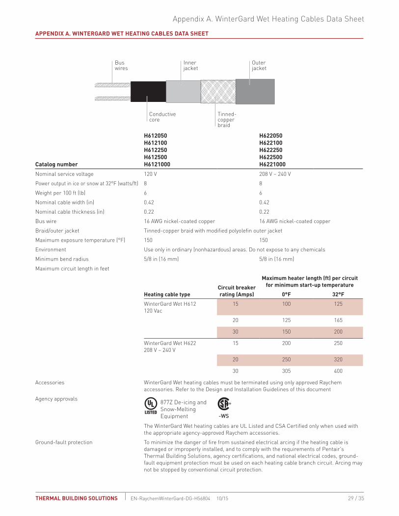
APPENdIx A. WINTERGARd WET HEATING CAbLES dATA SHEET
Buswires
Conductivecore
Innerjacket
Tinned-copperbraid
Outerjacket
Catalog number
H612050H612100H612250H612500H6121000
H622050H622100H622250H622500H6221000
Nominal service voltage 120 V 208 V – 240 V
Power output in ice or snow at 32°F (watts/ft) 8 8
Weight per 100 ft (lb) 6 6
Nominal cable width (in) 0.42 0.42
Nominal cable thickness (in) 0.22 0.22
Bus wire 16 AWG nickel-coated copper 16 AWG nickel-coated copper
Braid/outer jacket Tinned-copper braid with modified polyolefin outer jacket
Maximum exposure temperature (°F) 150 150
Environment Use only in ordinary (nonhazardous) areas. Do not expose to any chemicals
Minimum bend radius 5/8 in (16 mm) 5/8 in (16 mm)
Maximum circuit length in feet
Heating cable typeCircuit breaker rating (Amps)
Maximum heater length (ft) per circuit for minimum start-up temperature
0°F 32°F
WinterGard Wet H612 120 Vac
15 100 125
20 125 165
30 150 200
WinterGard Wet H622 208 V – 240 V
15 200 250
20 250 320
30 305 400
Accessories WinterGard Wet heating cables must be terminated using only approved Raychem accessories. Refer to the Design and Installation Guidelines of this document
Agency approvals 877Z De-icing and Snow-Melting Equipment -WS
The WinterGard Wet heating cables are UL Listed and CSA Certified only when used with the appropriate agency-approved Raychem accessories.
Ground-fault protection To minimize the danger of fire from sustained electrical arcing if the heating cable is damaged or improperly installed, and to comply with the requirements of Pentair's Thermal Building Solutions, agency certifications, and national electrical codes, ground-fault equipment protection must be used on each heating cable branch circuit. Arcing may not be stopped by conventional circuit protection.

30 / 35
WinterGard Wet SyStem deSiGn, inStallation and maintenance Guide
THERMAL buiLding SOLuTiOnSen-raychemWinterGard-dG-H56804 10/15
APPENdIx b. WINTERGARd WET SySTEM LIMITEd WARRANTy
Pentair Thermal Management warrants all goods listed below against faulty workmanship and use of defective materials when such goods are properly installed, operated, and maintained according to product documentation. All documentation regarding proper use and installation can be found on our web site at www.pentairthermal.com.
This warranty remains in force for a period of two (2) years from date of purchase.
This warranty is only valid for products purchased and installed within the United States, Canada, Central American, or South American countries on or after May 1, 2013. This warranty can be amended only by a written instrument signed by a duly au-thorized officer of Pentair Thermal Management.
brand Type
Raychem Heating cables, connection kits and accessories
• What Will We do to Correct Problems?Pentair Thermal Management will examine and confirm that any alleged product issue covered by this Limited Warranty ac-tually exists and occurred in the course of proper and normal use and was not caused by accident, misuse, neglect, alteration or improper installation, operation, maintenance, repair, or testing, or such other cause outside of the responsibility of Pentair Thermal Management under this Limited Warranty. Pentair Thermal Management will repair such goods or supply replace-ment goods or credit Buyer’s account for goods covered by this Limited Product Warranty, whichever Pentair Thermal Manage-ment may elect at its sole discretion.
• How do you Get Service? The Buyer should promptly notify Pentair Thermal Management, or their Pentair Thermal Management Representative, either by written correspondence or by e-mail within thirty (30) days after discovery of an alleged warranty issue. Detailed warranty claim information will be requested at this time and must be supplied by the Buyer. The Buyer may then be asked to return the goods, postage paid, to the location given by Pentair Thermal Management.
• What does This Product Warranty Not Cover? Goods subjected to misuse, neglect, alteration or improper installation, operation, maintenance, repair, or testing (or such oth-er act or omission, not attributable to Pentair Thermal Management) are not covered by this Limited Product Warranty. Pentair Thermal Management shall in no event be liable for the cost of removal or installation, for loss or damage to or loss of use of facilities or other property, loss of revenue, loss of use of revenue, loss of anticipated profits, or other damages or costs of any kind whatsoever, whether direct, indirect, incidental, or consequential, and in no event shall Pentair Thermal Management’s liability exceed an amount equal to the sales price.
• What Must you do to Keep the Warranty in Effect?Properly install, operate and maintain your Pentair Thermal Management system as specified in the associated Pentair Ther-mal Management installation literature.
• How does State/Provincial Law Relate To This Warranty? THE FOREGOING WARRANTY IS IN LIEU OF ALL OTHER REPRESENTATIONS, WARRANTIES, OR CONDITIONS, EXPRESS OR IMPLIED, INCLUDING WITHOUT LIMITATION ANY IMPLIED WARRANTY OF MERCHANTABILITY, FITNESS FOR A PARTICULAR PURPOSE OR NONINFRINGEMENT, AND OF ANY OTHER OBLIGATION OR LIABILITY ON THE PART OF PENTAIR THERMAL MANAGEMENT, WHETHER BY STATUTE, CONTRACT, STRICT LIABILITY, TORT OR OTHERWISE.
If the goods are a consumer product in Buyer’s jurisdiction, Buyer may have additional legal rights under the applicable nation-al/state/provincial legislation governing the sale of consumer goods. As a result, the above exclusions and/or limitations on the warranty may or may not apply.
31 / 35
Design Worksheet
THERMAL buiLding SOLuTiOnS EN-RaychemWinterGard-DG-H56804 10/15
dESIGN WORKSHEET
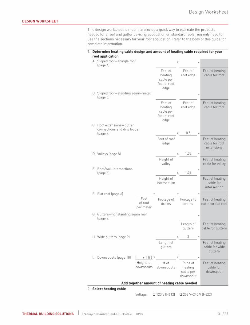
This design worksheet is meant to provide a quick way to estimate the products needed for a roof and gutter de-icing application on standard roofs. You only need to use the sections necessary for your roof application. Refer to the body of this guide for complete information.
1. determine heating cable design and amount of heating cable required for your roof applicationA. Sloped roof—shingle roof
(page 4)x =
Feet of heating
cable per foot of roof
edge
Feet of roof edge
Feet of heating cable for roof
B. Sloped roof—standing seam–metal (page 5)
=
Feet of heating
cable per foot of roof
edge
Feet of roof edge
Feet of heating cable for roof
C. Roof extensions—gutter connections and drip loops (page 7) x 0.5 =
Feet of roof edge
Feet of heating cable for roof
extensions
D. Valleys (page 8) x 1.33 =
Height of valley
Feet of heating cable for valley
E. Roof/wall intersections (page 8) x 1.33
=
Height of intersection
Feet of heating cable for
intersection
F. Flat roof (page 6) + + =Feet
of roof perimeter
Footage of drains
Footage to drains
Feet of heating cable for flat roof
G. Gutters—nonstanding seam roof (page 9)
=
Length of gutters
Feet of heating cable for gutters
H. Wide gutters (page 9) x 2 =
Length of gutters
Feet of heating cable for wide
gutters
I. Downspouts (page 10) ( + 1 ft ) x x =Height of
downspouts# of
downspoutsRuns of heating
cable per downspout
Feet of heating cable for
downspout
Add together amount of heating cable needed2. Select heating cable
Voltage T 120 V (H612) T 208 V–240 V (H622)

32 / 35
WinterGard Wet SyStem deSiGn, inStallation and maintenance Guide
THERMAL buiLding SOLuTiOnSen-raychemWinterGard-dG-H56804 10/15
3. determine number of circuits
27 or 30-mA ground-fault circuit breaker size available (check one): T 15 A T 20 A T 30 A
Using Table 8 on page 21, determine the maximum circuit length allowed: Feet max.
Total heating cable length divided by maximum circuit length allowed equals minimum number of circuits required
÷ =
Heating cable length
Max. circuit length
# of circuits required
4. Select accessories. Determine quantity of accessories and heating cable allowance (from Table 7 on page 19).
A. Power connection =
# of circuits
# of power connection kits
x 1 ft =
# of power connection
kits
Heating cable accessory allowance
B. Tee connection =
# of tees # of tee kits
x 2 ft =
# of tee kits Heating cable component allowance
C. End seal (included in power connection kits and tee kits)
x 0.5 ft =
# of end seals
Heating cable component allowance
5. determine total heating cable required.
A. Heating cable length (from Worksheet Step 1) =
B. Accessory heating cable allowances (Worksheet Step 4) =
C. Amount of extra heating cable needed =
D. Add A + B + C to get total amount of heating cable needed. Recheck number of circuits (Worksheet Step 3)
=

33 / 35
Design Worksheet
THERMAL buiLding SOLuTiOnS EN-RaychemWinterGard-DG-H56804 10/15
6. Select attachment accessories. Select the attachment method from Table 3 on page 11. Determine the minimum quantity of attachment accessories required.
A. Sloped shake or shingle roof ÷ 7 =
Roof length in feet
# of packages of H913 clips
÷ 35 =
Roof length in feet
# # of boxes of H914 clips
B. Other sloped nonstanding-seam roof x 4 =
# of seams traced
# of H913 or H914 clips or
other clips
C. Standing-seam metal roof ÷ x 2 =
Roof length in
feet
Seam spacing in
feet
# of H913 or H914 clips
D. Flat roof ÷ 5 =
Heating cable length
Belt loops
E. Downspouts x =
# of downspouts
# of runs of heating cable per
downspout
# of H915 downspout
hangers
7. Select control method. Select the method of control from “Step 3. Control” on page 16.
A. Manual control
B. Ambient thermostat T AMC-F5 T AMC-1A T EC-TS
C. Automatic controller T PD-Pro T GF-Pro T LCD-8
D. Sensors T CIT-1 T GIT-1
8. Fill in bill of Materials. See Table 7 on page 19 for a complete description of accessories.
Quantity Units description Catalog numbers
feet Heating cable H612 or H622
each Power connection kits H900, H908
each Splice kits H910
each Tee kits H910
each Roof clips H913 or H914
each Downspout hangers H915
each Cable ties, UV-resistant N/A


THERMAL MANAGEMENT SOLUTIONSEN-RaychemWinterGard-DG-H56804 10/13i / ii
NORTH AMERICA Tel: +1.800.545.6258Fax: +1.800.527.5703Tel: +1.650.216.1526Fax: [email protected]
Pentair, WinterGard and WinterGard Wet are owned by Pentair or its global affiliates. All other brand or product names are trademarks or registered marks of their respective owners. Because we are continuously improving our products and services, Pentair reserves the right to change specifications without prior notice. Pentair is an equal opportunity employer.
© 2000-2015 Pentair.
WWW.PENTAIRTHERMAL.COM
EN-RaychemWinterGard-DG-H56804 10/15THERMAL bUILdING SOLUTIONS