wireless 3g systems
TRANSCRIPT
8/4/2019 WIRELESS 3g Systems
http://slidepdf.com/reader/full/wireless-3g-systems 1/13
ABSTRACT

8/4/2019 WIRELESS 3g Systems
http://slidepdf.com/reader/full/wireless-3g-systems 2/13
Development of 3rd Generation Cellular Wireless (3G)Technologies is well underway within
Network Equipment Manufacturers. Most major wireless Service
Providers are beginning technology trials, but production networks will not be rolled out until 2001
at the earliest.This paper introduces 3G Wireless technology, standards and protocols. The main
components of a UMT S W-CDMA System are explained and a five stage testing strategy is defined.
This testing strategy is specifically designed to help accelerate the development and deployment of
3G Radio Access Network (RAN)
equipment. 3G systems will provide much greater levels of functionality and flexibility than any
predecessors. This of course means that such systems will be significantly more complex in design,
and correspondingly more difficult to get right.
Introduction:
8/4/2019 WIRELESS 3g Systems
http://slidepdf.com/reader/full/wireless-3g-systems 3/13
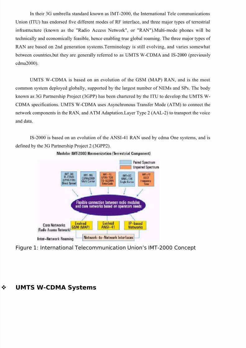
In their 3G umbrella standard known as IMT-2000, the International Tele communications
Union (ITU) has endorsed five different modes of RF interface, and three major types of terrestrial
infrastructure (known as the "Radio Access Network", or "RAN").Multi-mode phones will be
technically and economically feasible, hence enabling true global roaming. The three major types of
RAN are based on 2nd generation systems.Terminology is still evolving, and varies somewhat
between countries,but they are generally referred to as UMTS W-CDMA and IS-2000 (previously
cdma2000).
UMTS W-CDMA is based on an evolution of the GSM (MAP) RAN, and is the most
common system deployed globally, supported by the largest number of NEMs and SPs. The body
known as 3G Partnership Project (3GPP) has been chartered by the ITU to develop the UMTS W-
CDMA specifications. UMTS W-CDMA uses Asynchronous Transfer Mode (ATM) to connect the
network components in the RAN, and ATM Adaptation.Layer Type 2 (AAL-2) to transport the voice
and data.
IS-2000 is based on an evolution of the ANSI-41 RAN used by cdma One systems, and is
defined by the 3G Partnership Project 2 (3GPP2).
Figure 1: International Telecommunication Union’s IMT-2000 Concept
UMTS W-CDMA Systems
8/4/2019 WIRELESS 3g Systems
http://slidepdf.com/reader/full/wireless-3g-systems 4/13
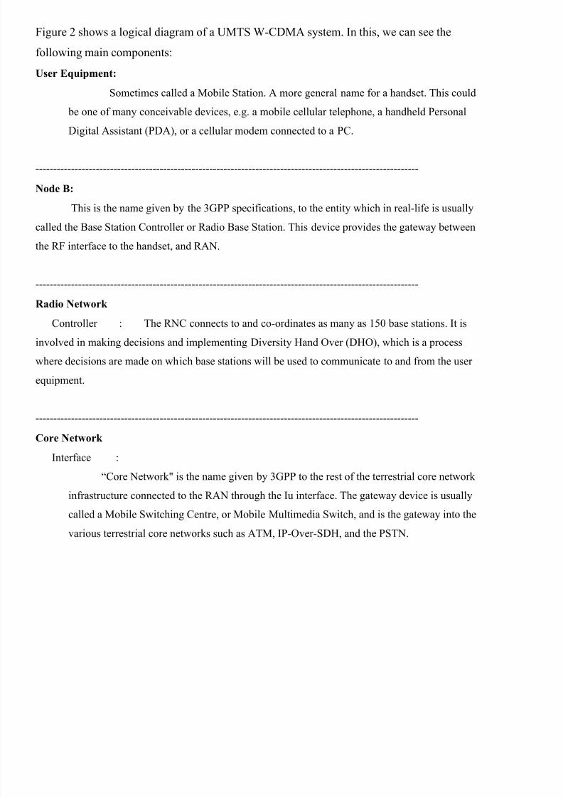
Figure 2 shows a logical diagram of a UMTS W-CDMA system. In this, we can see the
following main components:
User Equipment:
Sometimes called a Mobile Station. A more general name for a handset. This could
be one of many conceivable devices, e.g. a mobile cellular telephone, a handheld Personal
Digital Assistant (PDA), or a cellular modem connected to a PC.
------------------------------------------------------------------------------------------------------------
Node B:
This is the name given by the 3GPP specifications, to the entity which in real-life is usually
called the Base Station Controller or Radio Base Station. This device provides the gateway between
the RF interface to the handset, and RAN.
------------------------------------------------------------------------------------------------------------
Radio Network
Controller : The RNC connects to and co-ordinates as many as 150 base stations. It is
involved in making decisions and implementing Diversity Hand Over (DHO), which is a process
where decisions are made on which base stations will be used to communicate to and from the user
equipment.
------------------------------------------------------------------------------------------------------------Core Network
Interface :
“Core Network" is the name given by 3GPP to the rest of the terrestrial core network
infrastructure connected to the RAN through the Iu interface. The gateway device is usually
called a Mobile Switching Centre, or Mobile Multimedia Switch, and is the gateway into the
various terrestrial core networks such as ATM, IP-Over-SDH, and the PSTN.
8/4/2019 WIRELESS 3g Systems
http://slidepdf.com/reader/full/wireless-3g-systems 5/13
Figure 2: UMTS W-CDMA Logical Diagram
3GPP Protocols
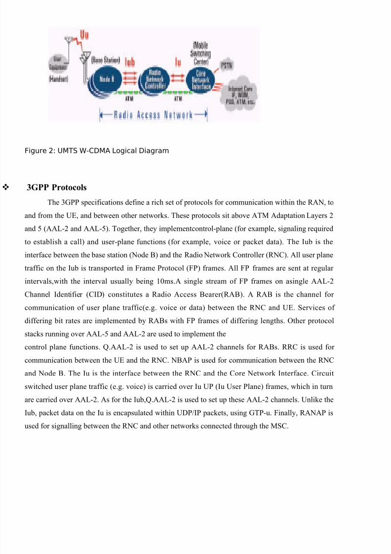
The 3GPP specifications define a rich set of protocols for communication within the RAN, to
and from the UE, and between other networks. These protocols sit above ATM Adaptation Layers 2
and 5 (AAL-2 and AAL-5). Together, they implementcontrol-plane (for example, signaling required
to establish a call) and user-plane functions (for example, voice or packet data). The Iub is the
interface between the base station (Node B) and the Radio Network Controller (RNC). All user plane
traffic on the Iub is transported in Frame Protocol (FP) frames. All FP frames are sent at regular
intervals,with the interval usually being 10ms.A single stream of FP frames on asingle AAL-2
Channel Identifier (CID) constitutes a Radio Access Bearer(RAB). A RAB is the channel for
communication of user plane traffic(e.g. voice or data) between the RNC and UE. Services of
differing bit rates are implemented by RABs with FP frames of differing lengths. Other protocol
stacks running over AAL-5 and AAL-2 are used to implement the
control plane functions. Q.AAL-2 is used to set up AAL-2 channels for RABs. RRC is used for
communication between the UE and the RNC. NBAP is used for communication between the RNC
and Node B. The Iu is the interface between the RNC and the Core Network Interface. Circuit
switched user plane traffic (e.g. voice) is carried over Iu UP (Iu User Plane) frames, which in turnare carried over AAL-2. As for the Iub,Q.AAL-2 is used to set up these AAL-2 channels. Unlike the
Iub, packet data on the Iu is encapsulated within UDP/IP packets, using GTP-u. Finally, RANAP is
used for signalling between the RNC and other networks connected through the MSC.

8/4/2019 WIRELESS 3g Systems
http://slidepdf.com/reader/full/wireless-3g-systems 6/13
Lubprotocol stack
Challenges Developing and Verifying UMTS W-CDMASystems
Due to the complexity of UMTS W-CDMA systems, large hardware,software, integration,
and QA teams are required to develop them. These developments are inevitably across more than
one site, and often more than one country and continent. Development of 3G systems can be broken
into the following major stages:
• Individual development of hardware, FPGA, and software modules
• Integration of hardware and software modules to form a component
• Debugging and verification of individual components
• Integration and verification of 3G systems made from these components
• Performance testing of individual components and the system as a whole.
• Guaranteeing conformance and interoperability.Of course, in real-life, many of these
activities occur simultaneously, and in an iterative fashion. There is usually little distinction between
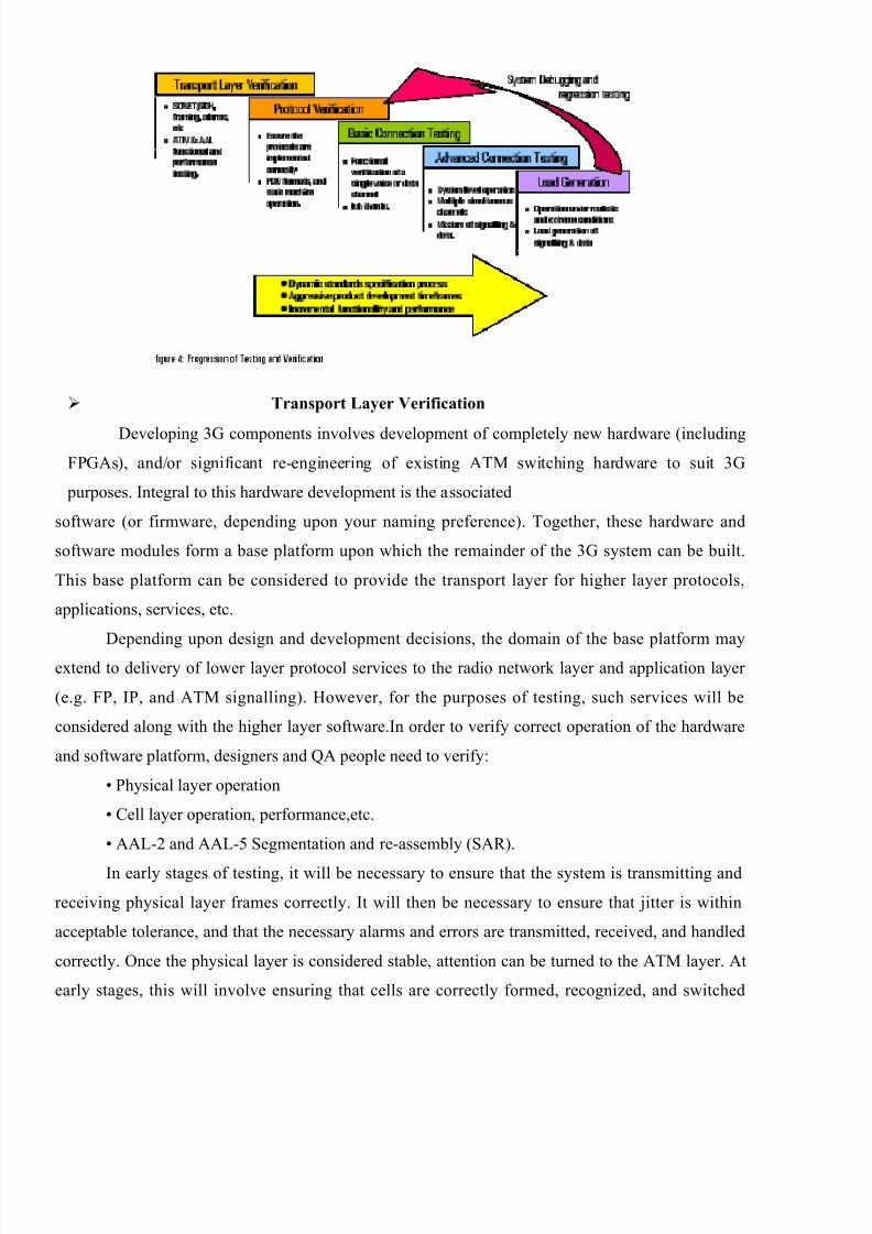
many activities, e.g. system-level and component-level verification and debugging.Figure 4 shows
the progression of debugging and verification of components that results from the product
development identified in the diagram. We have characterized the progression into five major categories:
• Transport Layer Verification
• Protocol Verification
• Basic Connection Test
• Advanced Connection Test
•LoadGeneration
8/4/2019 WIRELESS 3g Systems
http://slidepdf.com/reader/full/wireless-3g-systems 7/13
Transport Layer Verification
Developing 3G components involves development of completely new hardware (includingFPGAs), and/or significant re-engineering of existing ATM switching hardware to suit 3G
purposes. Integral to this hardware development is the associated
software (or firmware, depending upon your naming preference). Together, these hardware and
software modules form a base platform upon which the remainder of the 3G system can be built.
This base platform can be considered to provide the transport layer for higher layer protocols,
applications, services, etc.
Depending upon design and development decisions, the domain of the base platform may
extend to delivery of lower layer protocol services to the radio network layer and application layer
(e.g. FP, IP, and ATM signalling). However, for the purposes of testing, such services will be
considered along with the higher layer software.In order to verify correct operation of the hardware
and software platform, designers and QA people need to verify:
• Physical layer operation
• Cell layer operation, performance,etc.
• AAL-2 and AAL-5 Segmentation and re-assembly (SAR).
In early stages of testing, it will be necessary to ensure that the system is transmitting and
receiving physical layer frames correctly. It will then be necessary to ensure that jitter is within
acceptable tolerance, and that the necessary alarms and errors are transmitted, received, and handled
correctly. Once the physical layer is considered stable, attention can be turned to the ATM layer. At
early stages, this will involve ensuring that cells are correctly formed, recognized, and switched
8/4/2019 WIRELESS 3g Systems
http://slidepdf.com/reader/full/wireless-3g-systems 8/13
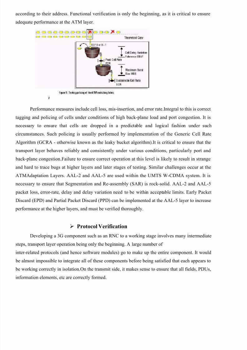
according to their address. Functional verification is only the beginning, as it is critical to ensure
adequate performance at the ATM layer.
Performance measures include cell loss, mis-insertion, and error rate.Integral to this is correct
tagging and policing of cells under conditions of high back-plane load and port congestion. It is
necessary to ensure that cells are dropped in a predictable and logical fashion under such
circumstances. Such policing is usually performed by implementation of the Generic Cell Rate
Algorithm (GCRA - otherwise known as the leaky bucket algorithm).It is critical to ensure that the
transport layer behaves reliably and consistently under various conditions, particularly port and
back-plane congestion.Failure to ensure correct operation at this level is likely to result in strange
and hard to trace bugs at higher layers and later stages of testing. Similar challenges occur at the
ATMAdaptation Layers. AAL-2 and AAL-5 are used within the UMTS W-CDMA system. It is
necessary to ensure that Segmentation and Re-assembly (SAR) is rock-solid. AAL-2 and AAL-5 packet loss, error-rate, delay and delay variation need to be within acceptable limits. Early Packet
Discard (EPD) and Partial Packet Discard (PPD) can be implemented at the AAL-5 layer to increase
performance at the higher layers, and must be verified thoroughly.
Protocol Verification
Developing a 3G component such as an RNC to a working stage involves many intermediate
steps, transport layer operation being only the beginning. A large number of inter-related protocols (and hence software modules) go to make up the entire component. It would
be almost impossible to integrate all of these components before being satisfied that each appears to
be working correctly in isolation.On the transmit side, it makes sense to ensure that all fields, PDUs,
information elements, etc are correctly formed.

8/4/2019 WIRELESS 3g Systems
http://slidepdf.com/reader/full/wireless-3g-systems 9/13
On the receive side,you need to be confident that the protocols are being interpreted
correctly, and that out-of-range values and incorrectly formed PDU’s are handled in an acceptable,
repeatable, and predictable fashion.As the protocol software may not be integrated with the
hardware, early phases of verification would most likely involve software test scripts. As thesoftware is integrated onto the hardware, testing would progress to stimulus testing only (perhaps
using trace messages or a debugger),
through to full stimulus response testing. figure 6 attempts to illustrate this.
Once this testing has been completed, testing can progress to verification that the state
machines are correctly implemented. Again, predictable and repeatable behaviour under errored
conditions is crucial. Test cases should include handling of messages that are sent out of sequence,
and/or with an out-of range value. In keeping with the incremental approach to development and
verification, the system under test (SUT) would not yet have implemented timers in the state
machines at the protocol layer being tested. This simplifies the test scenarios, by not having to deal
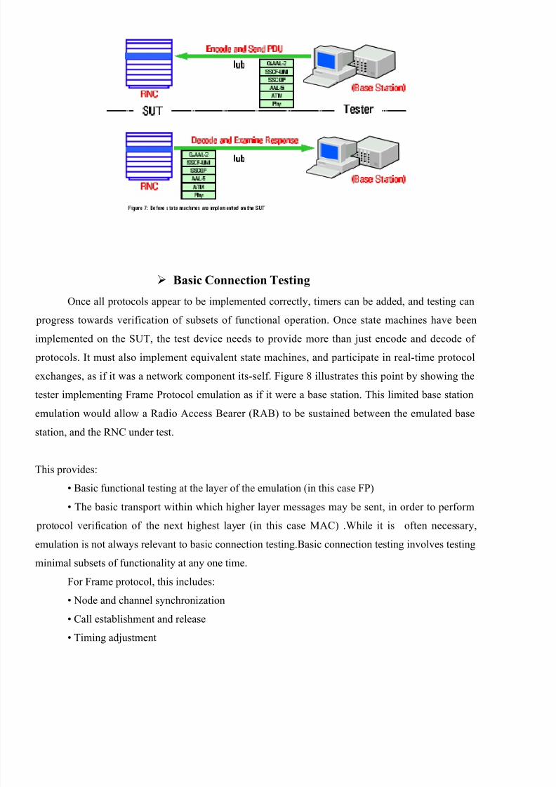
with the added complexity of interacting with the SUT in real-time. A human can send a message
and examine the response at his or her leisure, before progressing on to the next state, or test case
(see figure 7). Note that in order test at a particular protocol layer, it may be necessary for the tester
to implement emulation of protocols that are below that layer in the stack. For example, in order to
test at the Q.AAL-2 layer using encode/decode techniques, it would be necessary for the tester to
implement SSCOP emulation (which involves re-transmission of data in order to provide reliabletransport).Emulation is not relevant to all protocols. It is only relevant to protocols that involve state
machines and/or timers. Emulation will be discussed more in the coming section.
8/4/2019 WIRELESS 3g Systems
http://slidepdf.com/reader/full/wireless-3g-systems 10/13
Basic Connection Testing
Once all protocols appear to be implemented correctly, timers can be added, and testing can
progress towards verification of subsets of functional operation. Once state machines have been
implemented on the SUT, the test device needs to provide more than just encode and decode of
protocols. It must also implement equivalent state machines, and participate in real-time protocol
exchanges, as if it was a network component its-self. Figure 8 illustrates this point by showing the
tester implementing Frame Protocol emulation as if it were a base station. This limited base station
emulation would allow a Radio Access Bearer (RAB) to be sustained between the emulated basestation, and the RNC under test.
This provides:
• Basic functional testing at the layer of the emulation (in this case FP)
• The basic transport within which higher layer messages may be sent, in order to perform
protocol verification of the next highest layer (in this case MAC) .While it is often necessary,
emulation is not always relevant to basic connection testing.Basic connection testing involves testing
minimal subsets of functionality at any one time.
For Frame protocol, this includes:
• Node and channel synchronization
• Call establishment and release
• Timing adjustment
8/4/2019 WIRELESS 3g Systems
http://slidepdf.com/reader/full/wireless-3g-systems 11/13
These pieces of functionality require emulation at the FP layer, because FP involves both
state machines and timers. NBAP has neither, and so emulation is not relevant to testing that layer.
The tester would however have to emulate SSCOP (which is below NBAP in the protocol stack).
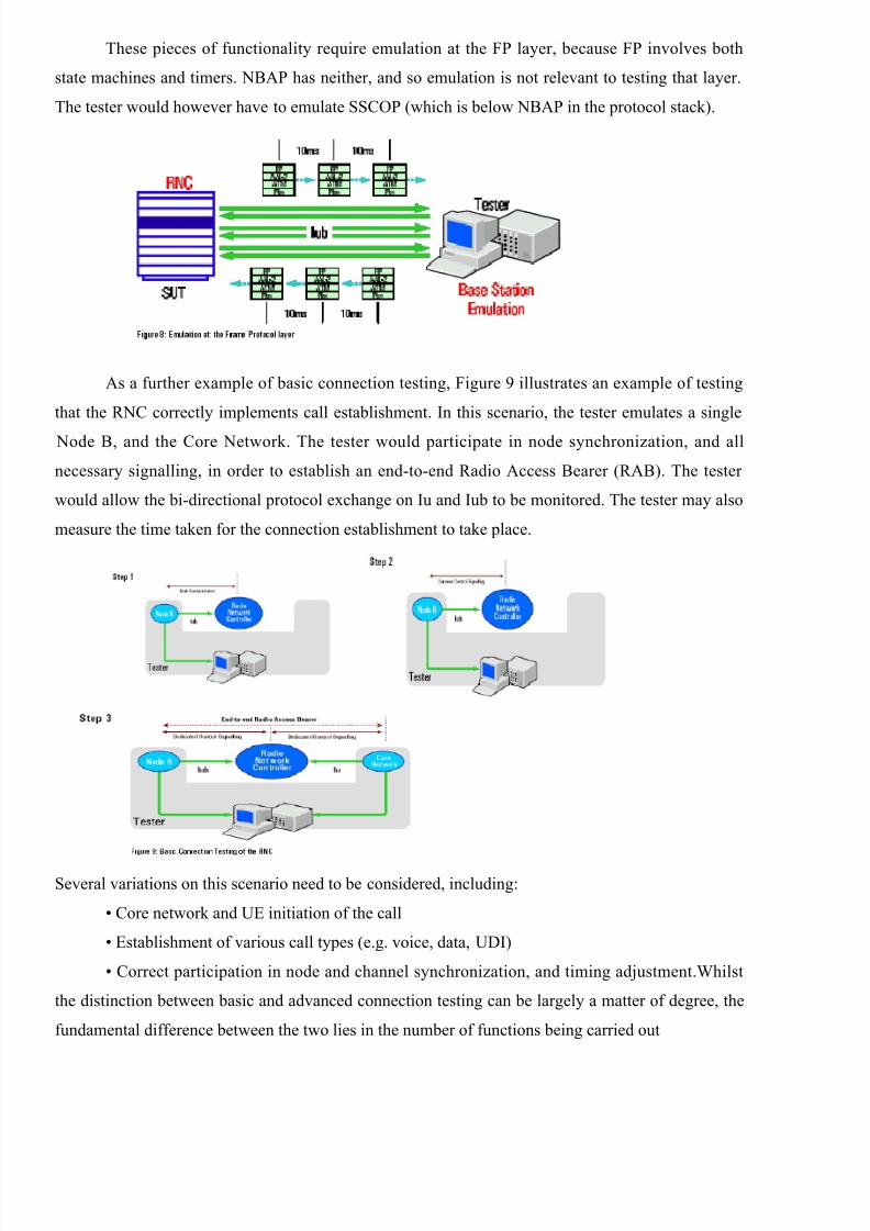
As a further example of basic connection testing, Figure 9 illustrates an example of testing
that the RNC correctly implements call establishment. In this scenario, the tester emulates a single
Node B, and the Core Network. The tester would participate in node synchronization, and all
necessary signalling, in order to establish an end-to-end Radio Access Bearer (RAB). The tester
would allow the bi-directional protocol exchange on Iu and Iub to be monitored. The tester may also
measure the time taken for the connection establishment to take place.
Several variations on this scenario need to be considered, including:
• Core network and UE initiation of the call
• Establishment of various call types (e.g. voice, data, UDI)
• Correct participation in node and channel synchronization, and timing adjustment.Whilst
the distinction between basic and advanced connection testing can be largely a matter of degree, the
fundamental difference between the two lies in the number of functions being carried out
8/4/2019 WIRELESS 3g Systems
http://slidepdf.com/reader/full/wireless-3g-systems 12/13
simultaneously. Basic connection testing involves testing a minimum subset of functionality
at any one time.
Advanced Connection Test
Advanced Connection testing involves testing and verification of a network component,
where different and/or multiple similar functions are occurring at once. This increased number of
simultaneous functions may be in order to test a more complex aggregate function such as hand-
over, or may be in order to test how the SUT behaves as more than one function is performed
simultaneously.The goal of advanced connection testing is to verify correct operation, as the various
functions the component must perform, are progressively developed and integrated. The theoretical
end-point is to verify that the SUT operates correctly for the complete set of functions that it must
perform (both simultaneous and sequential). Examples of advanced connection testing include:
• Handling of multiple simultaneous UEs
• Handling of multiple RABs of various types (Voice, UDI, Data)
• Execution of Diversity Handover (DHO)
Load generation
The performance of each component, and the 3G system as a whole is critical to characterize
and understand, before rolling out a 3G service. Service Providers will be keen to understand the
performance of the base stations, RNCs, and core network interfaces, as it has a direct affect on thecost of installing and operating a 3G system. Performance will be key to their selection of
manufacturer(s), and deciding optimum network topology. Each component in the UMTS W-CDMA
system can be a potential bottle-neck to overall system performance, however the RNC is arguably
the most critical. Within the RNC, the bottle-neck will generally be in processing power to handle
the large number of simultaneous instances of protocol stacks and state machines, making up the
control and user plane data. This will manifest it’s self in the maximum number of:
• Base stations that can be supported per RNC.
• UEs that can be supported per RNC.
• Busy Hour Call Attempts (BHCA) under various conditions.
• Registered users, both home and roaming
• Active users under various conditions
• Simultaneous open calls
8/4/2019 WIRELESS 3g Systems
http://slidepdf.com/reader/full/wireless-3g-systems 13/13
The key to testing performance is emulation of real-life conditions, as well as extreme
conditions. It is necessary to simulate various mixtures of voice, UDI, and data, combined with
various scenarios of typical end-user activity, combined with mobility (and hence DHO activity). In
order to facilitate this, it is desirable to specify scenarios in terms of the problem domain, rather than
the protocols, signalling rates, etc. The ideal level of scenario building would be to specify scenarios
in terms of groups of handsets with particular behaviour profiles, e.g.:
• Type of device, e.g. mobile phone, video phone, web browser, etc
• level and profile of use, e.g. two voice calls per hour plus 500Kb/h of interactive data
content, peaking at 11pm.
• Speed and direction of travel
Conclusion
3G cellular wireless technology provides much greater levels of functionality and flexibilitythan previous generations. 3G offers improved RF spectral efficiency and higher bit rates. While the
focus for the first 3G systems appears to be voice and limited data services, 3G is also expected to
become a significant Internet access technology.As always, equipment manufacturers that are early
to market will gain a big jump on the competition. However, performance of 3G systems will be just
as important as a competitive differentiator. The only way to achieve both objectives will be through
a carefully planned and streamlined test and verification strategy.