wireless
TRANSCRIPT
© S
AN
S In
stitu
te 2
004,
Aut
hor r
etai
ns fu
ll ri
ghts
.Key fingerprint = AF19 FA27 2F94 998D FDB5 DE3D F8B5 06E4 A169 4E46
© SANS Institute 2004, As part of the Information Security Reading Room Author retains full rights.
802.11i (How we got here and where are we headed)
By: Elio Perez
GSEC Certification, Version 1.4b Option1
Orlando, FL. August 21, 2004
1
© S
AN
S In
stitu
te 2
004,
Aut
hor r
etai
ns fu
ll ri
ghts
.Key fingerprint = AF19 FA27 2F94 998D FDB5 DE3D F8B5 06E4 A169 4E46
© SANS Institute 2004, As part of the Information Security Reading Room Author retains full rights.
802.11i (How we got here and where we are headed) Elio Perez GSEC Practical 1.4b Option 1 August 21, 2004 Abstract This paper will focus on the current IEEE1 802.11i standard and the components that comprise the standard. It will show how the standard ensures the integrity of the CIA triad in an effort to restore confidence in corporate WLANs. The Confidentiality, Integrity, and Availability triad is often taken for granted, but it is the criteria that any security infrastructure should meet. I believe that corporate WLAN implementations have been curtailed due to the lack of a truly secure standard. Perhaps a better word than curtailed is underutilized. I believe corporations have found a place for WLANs, but due to their lack of standardized and reliable security, they are not being used to their fullest potential. While some work has been done to remediate some of the shortcomings of WEP by both individual vendors and the Wi-Fi Alliance2, the IEEE has responded to the need for a formal standard. The committee has taken “best-of-breed” authentication, encryption, and authorization standards and has combined them to create what are to be called Robust Secure Networks or RSNs. The implementation recommendations in this paper will focus on enterprise implementations of the 802.11i standard while looking into the past deficiencies of WLAN security and attempts to remediate them. At the time of this writing, the draft was ratified and the standard approved on June 25, 2004. Wireless LANs are being implemented more and more in homes, airports, and even your neighborhood coffee shops. Different implementations obviously require different levels of security based on the sensitivity of the data they are there to transmit. I will focus on what I believe to be the implementation that needs the most attention, corporate WLANs. Corporate WLANs are used to communicate widely diverse types of data. They can transfer everything from a company’s secret recipe to a patient’s health information. They can be used to communicate across departments or across campuses. The history of Wireless LAN security has been full of broken promises, erroneous assumptions, interoperability issues and what has plagued this technology the most, a lack of reliable security standards. Through personal experience, I have seen the implementation of a WLAN not even considered due to security and interoperability concerns when a project clearly called for such an implementation. I have seen a company spend double or triple the cost for a wired solution when a wireless solution was much more practical. This was the reason I chose to write about the 802.11i standard and the steps the IEEE has taken towards restoring faith in the security of 802.11. WLAN Security: A brief history 1 http://www.ieee.org2 http://www.wi-fi.org
2

© S
AN
S In
stitu
te 2
004,
Aut
hor r
etai
ns fu
ll ri
ghts
.Key fingerprint = AF19 FA27 2F94 998D FDB5 DE3D F8B5 06E4 A169 4E46
© SANS Institute 2004, As part of the Information Security Reading Room Author retains full rights.
In my opinion, to truly understand the importance of the 802.11i standard, we must revisit the history of Wireless LAN security. The history of WLAN security dates back to the initial realization of the potential dangers of wireless networks. The fact that a company’s network could now reach beyond its physical boundaries introduced new threats, vulnerabilities, and a broader threat matrix for corporations to defend. Once word began to spread that wireless access points sent out a beacon at specific intervals to announce their availability, tools such as Netstumbler3 led to the phenomenon known as “war driving4.” War driving quickly became a highly publicized hobby by the media. WLAN vendors, users, and administrators quickly realized the need to implement security standards as part of their WLAN infrastructures. The following will touch briefly on the two major security standards introduced prior to the ratification of 802.11i, WEP and WPA. I will examine both standards and their attempts to secure WLANs. For additional information on WEP, please read “The Evolution of Wireless Security in 802.11 Networks: WEP, WPA, and 802.11 Standards” by Stanley Wong.5 For additional information on WPA, please read “How Things Work: WLAN Technologies and Security Mechanisms” by Anna Kagan.6 Summary of WEP When the IEEE standard for 802.11 was ratified, it included an optional security standard called WEP or Wireless Equivalency Protocol. Initially, many vendors failed to favor the implementation of WEP. They opted to recommend the implementation of MAC-Address filtering over the use of WEP. This quickly became a burden on IT departments as they needed to constantly keep track of the MAC addresses of all wireless network cards deployed throughout their enterprises.7 This coupled with the use of tools such as Kismet8 to discover valid MAC addresses and impersonate valid network clients, spurned interest in WEP. Initially, WEP was designed to provide a level of security equivalent to that of a wired network. It provided standards for authentication between network clients (initiators) and access points (responders) in addition to packet encryption. At its core, WEP uses the RC49 stream cipher for encryption and decryption of 802.11 packets. Due to export restrictions at the time the standard was released, the 40-bit length was initially used in WEP implementations.10 There are some that say that the failure of WEP was not due to the use of the RC4 algorithm, but its application to an environment radically different than that of a wired network. The
3 http://www.netstumbler.com4 http://searchsecurity.techtarget.com/sDefinition/0,,sid14_gci812927,00.html5 http://www.sans.org/rr/papers/index.php?id=11096 http://www.sans.org/rr/papers/index.php?id=13017 Gast, Matthew. “Wireless LAN Security: A Short History.” 19 April 2002. URL: http://www.oreillynet.com/lpt/a/1728 (26 June 2004.) 8 http://www.kismetwireless.net9 http://www.rsasecurity.com/rsalabs/node.asp?id=225010 Gast, Matthew. “Wireless LAN Security: A Short History.” 19 April 2002. URL: http://www.oreillynet.com/lpt/a/1728
3
© S
AN
S In
stitu
te 2
004,
Aut
hor r
etai
ns fu
ll ri
ghts
.Key fingerprint = AF19 FA27 2F94 998D FDB5 DE3D F8B5 06E4 A169 4E46
© SANS Institute 2004, As part of the Information Security Reading Room Author retains full rights.
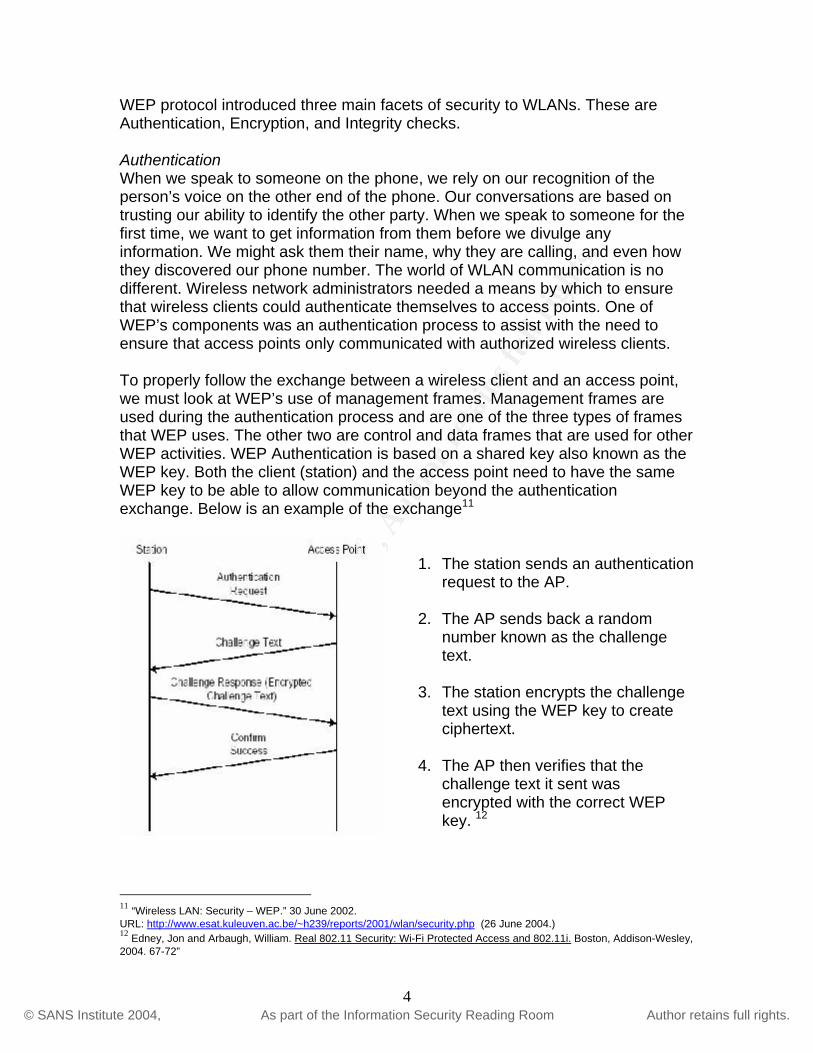
WEP protocol introduced three main facets of security to WLANs. These are Authentication, Encryption, and Integrity checks. Authentication When we speak to someone on the phone, we rely on our recognition of the person’s voice on the other end of the phone. Our conversations are based on trusting our ability to identify the other party. When we speak to someone for the first time, we want to get information from them before we divulge any information. We might ask them their name, why they are calling, and even how they discovered our phone number. The world of WLAN communication is no different. Wireless network administrators needed a means by which to ensure that wireless clients could authenticate themselves to access points. One of WEP’s components was an authentication process to assist with the need to ensure that access points only communicated with authorized wireless clients. To properly follow the exchange between a wireless client and an access point, we must look at WEP’s use of management frames. Management frames are used during the authentication process and are one of the three types of frames that WEP uses. The other two are control and data frames that are used for other WEP activities. WEP Authentication is based on a shared key also known as the WEP key. Both the client (station) and the access point need to have the same WEP key to be able to allow communication beyond the authentication exchange. Below is an example of the exchange11
1. The station sends an arequest to the AP.
uthentication
2. The AP sends back a random
number known as the challenge text.
3. The station encrypts the challenge
text using the WEP key to create ciphertext.
4. The AP then verifies that the
challenge text it sent was encrypted with the correct WEP key. 12
11 “Wireless LAN: Security – WEP.” 30 June 2002. URL: http://www.esat.kuleuven.ac.be/~h239/reports/2001/wlan/security.php (26 June 2004.) 12 Edney, Jon and Arbaugh, William. Real 802.11 Security: Wi-Fi Protected Access and 802.11i. Boston, Addison-Wesley, 2004. 67-72”
4
© S
AN
S In
stitu
te 2
004,
Aut
hor r
etai
ns fu
ll ri
ghts
.Key fingerprint = AF19 FA27 2F94 998D FDB5 DE3D F8B5 06E4 A169 4E46
© SANS Institute 2004, As part of the Information Security Reading Room Author retains full rights.
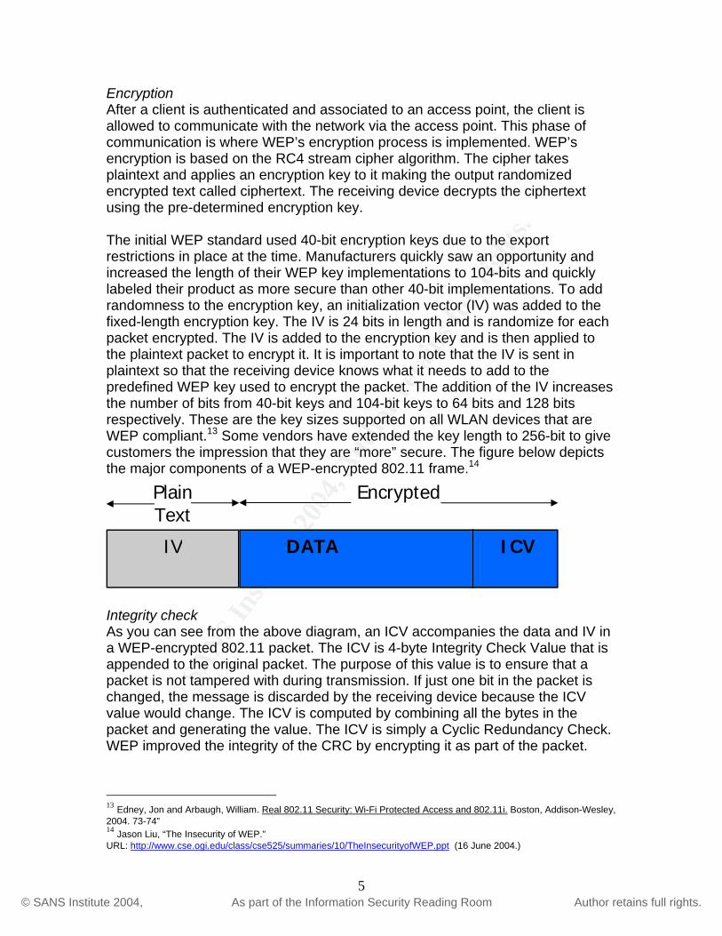
Encryption After a client is authenticated and associated to an access point, the client is allowed to communicate with the network via the access point. This phase of communication is where WEP’s encryption process is implemented. WEP’s encryption is based on the RC4 stream cipher algorithm. The cipher takes plaintext and applies an encryption key to it making the output randomized encrypted text called ciphertext. The receiving device decrypts the ciphertext using the pre-determined encryption key. The initial WEP standard used 40-bit encryption keys due to the export restrictions in place at the time. Manufacturers quickly saw an opportunity and increased the length of their WEP key implementations to 104-bits and quickly labeled their product as more secure than other 40-bit implementations. To add randomness to the encryption key, an initialization vector (IV) was added to the fixed-length encryption key. The IV is 24 bits in length and is randomize for each packet encrypted. The IV is added to the encryption key and is then applied to the plaintext packet to encrypt it. It is important to note that the IV is sent in plaintext so that the receiving device knows what it needs to add to the predefined WEP key used to encrypt the packet. The addition of the IV increases the number of bits from 40-bit keys and 104-bit keys to 64 bits and 128 bits respectively. These are the key sizes supported on all WLAN devices that are WEP compliant.13 Some vendors have extended the key length to 256-bit to give customers the impression that they are “more” secure. The figure below depicts the major components of a WEP-encrypted 802.11 frame.14
EncryptedPlain Text
DATA ICV IV
Integrity check As you can see from the above diagram, an ICV accompanies the data and IV in a WEP-encrypted 802.11 packet. The ICV is 4-byte Integrity Check Value that is appended to the original packet. The purpose of this value is to ensure that a packet is not tampered with during transmission. If just one bit in the packet is changed, the message is discarded by the receiving device because the ICV value would change. The ICV is computed by combining all the bytes in the packet and generating the value. The ICV is simply a Cyclic Redundancy Check. WEP improved the integrity of the CRC by encrypting it as part of the packet.
13 Edney, Jon and Arbaugh, William. Real 802.11 Security: Wi-Fi Protected Access and 802.11i. Boston, Addison-Wesley, 2004. 73-74” 14 Jason Liu, “The Insecurity of WEP.” URL: http://www.cse.ogi.edu/class/cse525/summaries/10/TheInsecurityofWEP.ppt (16 June 2004.)
5

© S
AN
S In
stitu
te 2
004,
Aut
hor r
etai
ns fu
ll ri
ghts
.Key fingerprint = AF19 FA27 2F94 998D FDB5 DE3D F8B5 06E4 A169 4E46
© SANS Institute 2004, As part of the Information Security Reading Room Author retains full rights.
Therefore, at the time of initial release, it was believed that encrypting the CRC value would prevent tampering and ensure integrity.15
WEP Deficiencies As the popularity of WLANS began to grow, so did the realization that implementing them without WEP was not a wise decision. After all, it was being touted as a means by which to secure the “open” WLANS that were being discovered by war drivers. As WEP’s popularity began to grow, so did the security community’s curiosity as to how secure WEP truly was. This all came to ahead in 2000-2001 when a series of papers were written and published that proved that WEP and the RC4 algorithm it used, failed to provide the security it claimed to ensure.16 I will look at the deficiencies of WEP in the three major areas referenced earlier. Authentication The shared-key authentication method of WEP is deficient in providing a secure means of authenticating a station to an access point. Not only is it insecure, but it uses the same WEP key for authentication challenges and encryption. This sets the stage for attacks during the authentication exchange that can lead to the loss of integrity of the entire process. Using a passive eavesdropping attack, an attacker can listen in on one-leg of the authentication exchange. The attacker can then decipher the secret key used to XOR the plaintext. The process is as follows:
1. An attacker obtains the plaintext challenge that the access point sends to the station during step 2 of the authentication phase mentioned on page 3.
2. During step 3, the station XORs the plaintext with the secret key to create ciphertext. The attacker also has the encrypted response at this point.
3. Using the fixed structure of the protocol, the attacker can use the following process to decipher the WEP key used in the exchange:
For the purposes of the following demonstration, P = Plaintext, R = Random Challenge, and C = Ciphertext. The most important factor in this equation is the Random Challenge and the fact that it remains confidential throughout the entire authentication process.
• The XOR process of WEP shows that: CRP =⊕ . • Therefore, keeping in mind that the attacker already has two pieces of the
above equation P & C, the attacker can discover the secret key using the following equation .RPC =⊕ 17
15 Edney, Jon and Arbaugh, William. Real 802.11 Security: Wi-Fi Protected Access and 802.11i. Boston, Addison-Wesley, 2004. 84-85. 16 Gast, Matthew. “Wireless LAN Security: A brief History.” 19 April 2002. URL: http://www.oreillynet.com/lpt/a/1728. (16 July 2004.) 17 Arbaugh, William A., Shankar, Narendar, Wan, Justin Y.C. “Your 802.11 Wireless Network has No Clothes.” 30 March 2001. URL: http://www.cs.umd.edu/~waa/wireless.pdf. (19 July 2004.)
6

© S
AN
S In
stitu
te 2
004,
Aut
hor r
etai
ns fu
ll ri
ghts
.Key fingerprint = AF19 FA27 2F94 998D FDB5 DE3D F8B5 06E4 A169 4E46
© SANS Institute 2004, As part of the Information Security Reading Room Author retains full rights.
After these findings were published, it was deemed that the shared-key authentication process was insecure and unnecessary. It was insecure because of the ability to spoof the identity of an attacker as a valid client and it was unnecessary because it caused more harm than good. By allowing the discovery of the WEP key during the authentication process, the integrity of the entire encryption process is compromised due to the fact that the same WEP key used during authentication is also the basis for WEP encryption. Few users now use shared-key encryption and simply set their wireless devices to open authentication allowing the devices to negotiate their association with a pre-determined key. This eliminates the possibility of an attacker discovering the WEP key by intercepting the authentication exchange. Encryption IV ReuseFor the sake of argument, let’s say that an administrator has recognized the issues with shared-key authentication and opted for an open authentication scheme. The most critical piece of the WEP puzzle remains the protection of the WEP key used in the encryption process. Because RC4 is a stream cipher, it was necessary for the architects of WEP to implement a random value that can be added so that the algorithm is set to a different initialization state before the encryption of each frame. This value is the aforementioned IV. Without this value, the algorithm would always begin in the same state and increment itself in the same manner for every frame. This would make the encryption useless. The use of the IV gave the impression that each frame would have a completely random and different IV value. This combined with the use of the RC4 algorithm would provide confidentiality to WLAN communication. In October of 2000, Jesse Walker of Intel Corporation authored a document entitled “IEEE P802.11 Wireless LANs: Unsafe at any key size; An analysis of the WEP encapsulation.” This document addressed the misconception that the deficiencies in WEP could be remedied by a longer key size. Mr. Walker contested that notion and documented the issues with IV reuse. As mentioned before, the IV used in WEP is 24 bits long. This gives WEP the possibility of 224
different IV values. The fact that the IV is 24 bits creates a very real possibility for IV collision. IV collisions occur when duplicate IVs are used. The chances of duplicate IVs are as follows:
• 1% after 582 encrypted frames • 10% after 1881 encrypted frames • 50% after 4,823 encrypted frames • 99% after 12,430 encrypted frames18
18 Walker, Jess R. “IEEE P802.11 Wireless LANs: Unsafe at any key size; An analysis of the WEP encapsulation.” 27 October 2000. URL: http:// www.dis.org/wl/pdf/unsafe.pdf (23 June 2004.)
7

© S
AN
S In
stitu
te 2
004,
Aut
hor r
etai
ns fu
ll ri
ghts
.Key fingerprint = AF19 FA27 2F94 998D FDB5 DE3D F8B5 06E4 A169 4E46
© SANS Institute 2004, As part of the Information Security Reading Room Author retains full rights.
Once an attacker begins to find duplicate IVs, they can begin to create an IV-WEP key combination database that can be used to either inject packets into a conversation or simply decode broadcast traffic. A complete database of WEP keys of any length with their corresponding IVs can easily be stored on today’s typical hard drives.19 RC4 Weak Keys The straw that broke the camel’s back so to speak was the 2001 publishing of “Weaknesses in the Key Scheduling Algorithm of RC4” by Scott Fluhrer, Itsik Mantin, and Adi Shamir.20 This, unlike previous documents about WEP’s deficiencies, discovered vulnerabilities in the RC4 algorithm itself. This paper basically discovered that certain keys had bits that when changed had a greater effect on the XORed data than others. There were also bits that when changed had no effect whatsoever on the output. They called these keys “weak keys.” This combined with that fact the keys are tied to IVs would guarantee that if a weak key is found, it could be exploited. The paper discusses what was to be the most devastating and advertised attack on WEP. The attack basically just required some patience on the attacker’s part to wait until a weak key was found and byte-by-byte of the secret key was deciphered. This attack is now exploited with products such as Airsnort 21 that discovers WEP keys in a matter of hours in some cases. Basically, the more packets the application can process, the faster the key is deciphered. Integrity As one can imagine, after the encryption mechanism of WEP is broken, any packet using WEP can be decrypted. WEP’s integrity check mechanism, the aforementioned ICV can also be deciphered once the key is public. Once the key is public, an attacker can hijack a transmission, tamper with the payload, and change the ICV to its original form to disguise the message as “unchanged” during transmission. In other words, WEP’s integrity check provides no integrity whatsoever. WEP Deficiency Summary As we can see from the discovery of various deficiencies in WEP, the protocol offered no protection against even the casual hacker. The protocol failed to satisfy all pieces of the CIA triad. Its attempts at Confidentiality by encrypting packets failed. It attempts to provide Integrity by implementing its ICV failed. Finally, its attempts to provide Availability with its Authentication model failed as well. WEP was quickly branded a protocol to implement because it was “better than doing nothing” as opposed to the secure protocol it was designed to be. The media was quick to publicize all the vulnerabilities of WEP’s encryption algorithm
19 Edney, Jon and Arbaugh, William. Real 802.11 Security: Wi-Fi Protected Access and 802.11i. Boston, Addison-Wesley, 2004. 96-98. 20 Fluhrer, Scott, Mantin, Itsik, Shamir, Adi. “Weaknesses in the Key Scheduling Algorithm of RC4” 2001. URL: http://www.drizzle.com/~aboba/IEEE/rc4_ksaproc.pdf (25 June 2004.) 21 http://airsnort.shmoo.com/
8
© S
AN
S In
stitu
te 2
004,
Aut
hor r
etai
ns fu
ll ri
ghts
.Key fingerprint = AF19 FA27 2F94 998D FDB5 DE3D F8B5 06E4 A169 4E46
© SANS Institute 2004, As part of the Information Security Reading Room Author retains full rights.
and the creation of applications that exploited these deficiencies began to put pressure on the IEEE and the Wi-Fi Alliance for a remedy to the broken standard. WPA/802.11iFor the purposes of this paper, I have decided to look at WPA and 802.11i at the same time. The fact that WPA is a subset of 802.11i will show that they both share many of the same goals and methods by which to achieve those goals. I will begin by looking at WPA and transition into 802.11i to show the differences between them. The IEEE and the Wi-Fi Alliance realized the need to look at WEP’s deficiencies and create a new standard. The IEEE began to look at what was coined 802.11i. It would be an addendum to the 802.11 standard regarding a new security model. The standard, when implemented correctly, would create what are called RSNs or Robust Security Networks. 802.11i would create standards that scale much better than WEP and provide an international standard that can be followed to secure WLANs. The problem was the fact that the 802.11i standard wasn’t going to ready for ratification anytime soon. In the end, the standard was ratified over 3 years later than expected. The standard was finally ratified on June 24, 2004.22
In 2001, the Wi-Fi alliance began to quickly realize that consumers needed an alternative to WEP sooner, rather than later. Realizing that Task Group i, the IEEE working group in charge of 802.11i, would not be ready to ratify their standard in time to meet with consumer demands, the Wi-Fi Alliance decided to create their own subset of 802.11i called WPA or Wi-Fi Protected Access. WPA was based on portions of the 802.11i standard that were already decided on before ratification of the standard. WPA was supported by a large number of vendors and consumer alike because implementing it would simply require a firmware upgrade to most WLAN devices. WPA and 802.11i specified new standards for authentication, encryption, and message integrity.23 Authentication A robust authentication standard is something that was missing from WEP and contributed to its demise. WPA/802.11i implements 802.1x for user authentication and key distribution. 802.1x is a port-based authentication mechanism used for both wired and wireless networks. One of the major advantages of using 802.1x is the fact that it can be used in conjunction with upper layer authentication protocols to provide access to the network. It can block access to network resources until a station is properly authenticated to an access point. The 802.1x authentication model is comprised of three types of
22 Fleishman, Glenn. “Caring About 802.11i.” 25 June 2004. URL: http://www.wifinetnews.com/archives/003939.html. (20 Aug 2004.) 23 Edney, Jon and Arbaugh, William. Real 802.11 Security: Wi-Fi Protected Access and 802.11i. Boston, Addison-Wesley, 2004. 96-98.
9
© S
AN
S In
stitu
te 2
004,
Aut
hor r
etai
ns fu
ll ri
ghts
.Key fingerprint = AF19 FA27 2F94 998D FDB5 DE3D F8B5 06E4 A169 4E46
© SANS Institute 2004, As part of the Information Security Reading Room Author retains full rights.
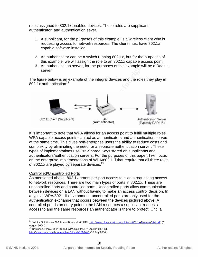
roles assigned to 802.1x-enabled devices. These roles are supplicant, authenticator, and authentication sever.
1. A supplicant, for the purposes of this example, is a wireless client who is requesting access to network resources. The client must have 802.1x capable software installed.
2. An authenticator can be a switch running 802.1x, but for the purposes of this example, we will assign the role to an 802.1x capable access point.
3. An authentication server, for the purposes of this example will be a Radius server.
The figure below is an example of the integral devices and the roles they play in 802.1x authentication24
(Authenticator)
It is important to note that WPA allows for an access point to fulfill multiple roles. WPA capable access points can act as authenticators and authentication servers at the same time. This gives non-enterprise users the ability to reduce costs and complexity by eliminating the need for a separate authentication server. These types of implementations use Pre-Shared Keys stored on supplicants and authenticators/authentication servers. For the purposes of this paper, I will focus on the enterprise implementations of WPA/802.11i that require that all three roles of 802.1x are played by separate devices.25
Controlled/Uncontrolled Ports As mentioned above, 802.1x grants per-port access to clients requesting access to network resources. There are two main types of ports in 802.1x. These are uncontrolled ports and controlled ports. Uncontrolled ports allow communication between devices on a LAN without having to make an access control decision. In a typical WPA/802.11i environment, uncontrolled ports are only used for the authentication exchange that occurs between the devices pictured above. A controlled port is an entry point to the LAN resources a supplicant requests access to and the same resources an authenticator is there to protect. Until a
24 “WLAN Solutions – 802.1x and Bluesocket.” URL: http://www.bluesocket.com/solutions/802.1x-Feature-Brief.pdf (6 August 2004.) 25 Robinson, Frank. “802.11i and WPA Up Close.” 1 April 2004. URL: http://www.nwc.com/showitem.jhtml?docid=1506ws1 (18 July 2004.)
10

© S
AN
S In
stitu
te 2
004,
Aut
hor r
etai
ns fu
ll ri
ghts
.Key fingerprint = AF19 FA27 2F94 998D FDB5 DE3D F8B5 06E4 A169 4E46
© SANS Institute 2004, As part of the Information Security Reading Room Author retains full rights.
client is authenticated by the authentication server, the only port that allows communication is the uncontrolled port. The figure below provides a visual representation of the two types of ports discussed above.26
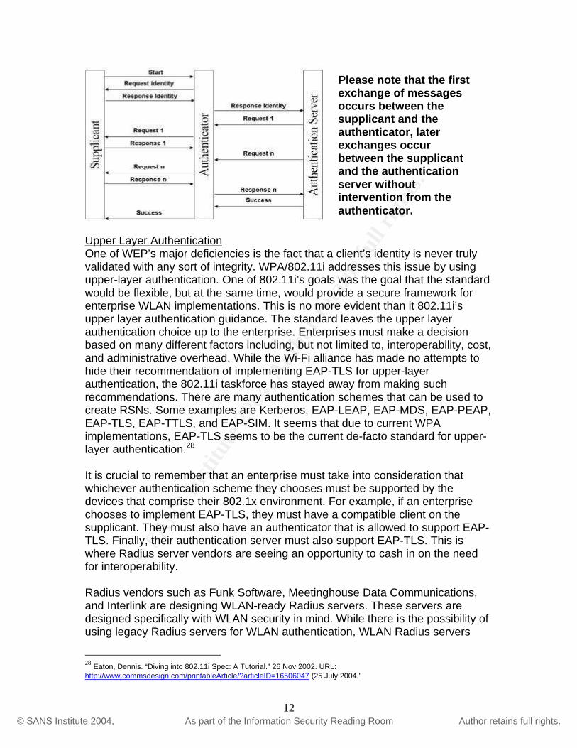
This diagram shows both the uncontrolled port used for authentication requests and the controlled port in its pre-authentication setting (left) and post-authentication setting (right.) As you can see, when a supplicant is successfully authenticated, the controlled port is considered authorized and communication through the logical port is allowed. Authentication Message Exchange The authentication exchange used in 802.1x takes place over Extensible Authentication Protocol or EAP. EAP is a protocol designed for use in transporting authentication messages. Before 802.1x became prominent in WLAN authentication, EAP was mainly used to authenticate dial-up users. In order for EAP messages to be transported on a LAN, they need to be encapsulated. IEEE 802.1x defined EAP over LAN or EAPOL to encapsulate EAP packets allowing them to be transported on a LAN. In a typical 802.1x authentication exchange, EAPOL messaged must travel between the supplicant, the authenticator, and the authentication server. The following is an example of the EAP message flow that occurs during 802.1x authentication:27
26 Eaton, Dennis. “Diving into the 802.11i Spec: A Tutorial.” 26 Nov 2004. URL: http://www.commsdesign.com/printableArticle/?articleID=16506047 (6 August 2004.) 27 Edney, Jon and Arbaugh, William. Real 802.11 Security: Wi-Fi Protected Access and 802.11i. Boston, Addison-Wesley, 2004. 135.
11
© S
AN
S In
stitu
te 2
004,
Aut
hor r
etai
ns fu
ll ri
ghts
.Key fingerprint = AF19 FA27 2F94 998D FDB5 DE3D F8B5 06E4 A169 4E46
© SANS Institute 2004, As part of the Information Security Reading Room Author retains full rights.
Please note that the first exchange of messages occurs between the supplicant and the authenticator, later exchanges occur between the supplicant and the authentication server without intervention from the authenticator.
Upper Layer Authentication One of WEP’s major deficiencies is the fact that a client’s identity is never truly validated with any sort of integrity. WPA/802.11i addresses this issue by using upper-layer authentication. One of 802.11i’s goals was the goal that the standard would be flexible, but at the same time, would provide a secure framework for enterprise WLAN implementations. This is no more evident than it 802.11i’s upper layer authentication guidance. The standard leaves the upper layer authentication choice up to the enterprise. Enterprises must make a decision based on many different factors including, but not limited to, interoperability, cost, and administrative overhead. While the Wi-Fi alliance has made no attempts to hide their recommendation of implementing EAP-TLS for upper-layer authentication, the 802.11i taskforce has stayed away from making such recommendations. There are many authentication schemes that can be used to create RSNs. Some examples are Kerberos, EAP-LEAP, EAP-MDS, EAP-PEAP, EAP-TLS, EAP-TTLS, and EAP-SIM. It seems that due to current WPA implementations, EAP-TLS seems to be the current de-facto standard for upper-layer authentication.28
It is crucial to remember that an enterprise must take into consideration that whichever authentication scheme they chooses must be supported by the devices that comprise their 802.1x environment. For example, if an enterprise chooses to implement EAP-TLS, they must have a compatible client on the supplicant. They must also have an authenticator that is allowed to support EAP-TLS. Finally, their authentication server must also support EAP-TLS. This is where Radius server vendors are seeing an opportunity to cash in on the need for interoperability. Radius vendors such as Funk Software, Meetinghouse Data Communications, and Interlink are designing WLAN-ready Radius servers. These servers are designed specifically with WLAN security in mind. While there is the possibility of using legacy Radius servers for WLAN authentication, WLAN Radius servers
28 Eaton, Dennis. “Diving into 802.11i Spec: A Tutorial.” 26 Nov 2002. URL: http://www.commsdesign.com/printableArticle/?articleID=16506047 (25 July 2004.”
12

© S
AN
S In
stitu
te 2
004,
Aut
hor r
etai
ns fu
ll ri
ghts
.Key fingerprint = AF19 FA27 2F94 998D FDB5 DE3D F8B5 06E4 A169 4E46
© SANS Institute 2004, As part of the Information Security Reading Room Author retains full rights.
give the enterprise the ability to handle all authentication exchanges on the WLAN. This makes isolating the entire WLAN infrastructure much easier and self-contained. One distinction that is noteworthy is that while WPA allows for the use of a PSK or Pre-Shared Key architecture as explained above as a replacement for a Radius server, 802.11i makes Radius practically a requirement. Many enterprises have found PSK to have a much higher administrative overhead due to the need to constantly manage the shared keys to ensure devices can communicate. 29
WPA/802.11i Key Management Many would argue that key management was at the core of WEP’s deficiencies and spawned the discovery of WEP’s major security issues. In response to the need for a more secure, scalable, and reliable key management system, the 802.11i group addressed the need. WPA and 802.11i use identical key management schemes. The only difference is the size of keys due to the inherent differences between TKIP (Temporal Key Integration Protocol) and AES-CCMP (counter mode with CBC-MAC.) The key management schemes used to create RSNs are hierarchal by design. There are two types of key generation management systems as part of WPA/802.11i. They are server-based keys that require the involvement of an authentication server to generate and manage server-based keys or the use of pre-shared keys. Complete 802.11i implementation requires the use of an authentication server to generate and manage keys. Smaller organizations and home users can use pre-shared key management. Please note however that just because a smaller organization or home user decides to implement a pre-shared key scheme, it is not equivalent to using WEP. It is simply using a different implementation of WPA/802.11i key management. This scheme simply removes the necessity of have keys automatically generated by an authentication server and requires the manual entry of keys for client and access point authentication. The security of WPA/802.11i is still in place, put in makes scaling and managing the environment more difficult due to the manual management of keys. Pre-shared key systems are used mostly in legacy WLAN equipment because they mostly require a firmware upgrade to be WPA compliant. This is more evidence of WPA’s goal of allowing legacy equipment to upgrade to a more secure environment without making their hardware obsolete. As I mentioned previously, I have attempted to focus on corporate WLAN security and will delve into the server-based scheme in the following sections. Key Generation and Management30 The server-based key hierarchy begins at the top with what is known as a pairwise master key or PMK. The creation of the pairwise master key is 29 Robinson, Frank. “802.11i and WPA Up Close.” 1 April 2004. URL: http://www.nwc.com/showitem.jhtml?docid=1506ws1 (18 July 2004.) 30 Edney, Jon and Arbaugh, William. Real 802.11 Security: Wi-Fi Protected Access and 802.11i. Boston, Addison-Wesley, 2004. 199-211
13
© S
AN
S In
stitu
te 2
004,
Aut
hor r
etai
ns fu
ll ri
ghts
.Key fingerprint = AF19 FA27 2F94 998D FDB5 DE3D F8B5 06E4 A169 4E46
© SANS Institute 2004, As part of the Information Security Reading Room Author retains full rights.
contingent on the upper-layer authentication protocol used during the 802.1x authorization and authentication phase. The protocols used in 802.1x are key-generation protocols that generate random key material that is used by the authentication server and the supplicant to generate a pair of identical PMKs. After the authentication process is completed, both the server and the supplicant have matching PMKs, but the access point needs a copy of the key as well. WPA specifies the use of Radius to copy the key from the server to the access point. 802.11i does not specify a means by which to get the key to the authenticator. Even though the same key is shared among the entities that need to communicate, communication is not allowed as of yet. The generation of temporal keys used for encryption and integrity are now ready for generation using the PMK. Temporal keys are generated to protect two processes during the communication process. Keys are needed to protect the data that is transferred and two more are generated to protect the EAPOL handshake that occurs between two devices. The keys generated are as follows:
• Data Encryption key (128 bits) • Data Integrity key (128 bits) • EAPOL-Key Encryption (128 bits) • EAPOL-Key Integrity key (128 bits)
These keys have been labeled temporal because they are temporary keys that are generated every time a device is associated to an access point in an RSN. These four keys are grouped together and called the pairwise transient key (PTK.) The total length of the PTK is 512 bits. To provide randomness to the creation of the temporal keys, nonce are generated by both devices and added to the PMK to generate the keys that comprise the PTK. The MAC address of both devices that have associated to themselves is also added to the computation of the PTK to ensure that the keys are bound to the two devices that created them. To summarize, the 4 temporal keys are generated by combining the PMK, a nonce from each client, and the MAC address of each client.31
As a final step before any access to network resources is granted to the a wireless client, the access point must prove its identity to the authentication server. The access point needs to prove to the authentication servers that it has the correct PMK. The copying of the PMK to an access point must occur using a secure channel. It is left to the user to specify how that secure channel is implemented. This process of identification happens during the temporal key generation process and is known as the four-way exchange. It is a process that when completed successfully is the final step towards allowing the client access to network resources. During the process the following occurs: 31 Cam-Winget, Nancy., et al. “IEEE 802.11i Overview.” URL: http://csrc.nist.gov/wireless/S10_802.11i%20Overview-jw1.pdf (21 June 2004.)
14
© S
AN
S In
stitu
te 2
004,
Aut
hor r
etai
ns fu
ll ri
ghts
.Key fingerprint = AF19 FA27 2F94 998D FDB5 DE3D F8B5 06E4 A169 4E46
© SANS Institute 2004, As part of the Information Security Reading Room Author retains full rights.
1. A pair of nonce are created by both the authenticator and the supplicant. The values are random of each other and are labeled an SNonce for the supplicant’s nonce and an ANonce for the authenticator’s nonce.
2. Temporal keys are generated. 3. The supplicant has proven to the authenticator that it knows the PMK. 4. Authenticator has proven knowledge of the PMK 5. Both of devices have turned on encryption for unicast packets.
Due to the fact that 802.11 communication also supports broadcast messages, WPA/802.11i also standardizes a process for group keys that ensure secure communication for broadcast messaging. Group keys are created because pairwise keys are unique to each device. Broadcast message encryption is more efficient when the same key is used to encrypt and decrypt the message. While it is possible for clients to use their unique pairwise key, it is inefficient to have each client encrypt and decrypt the message before passing it on. The creation and transmission of the group keys is done using the secure channel created by the pairwise keys when the clients associated to the access point. This makes the transmission of the key secure. Here is how the process works:
1. The access point chooses a 256-bit cryptographic-quality random number. That number becomes the GMK or group master key.
2. The GMK is used to create the Group Encryption Key (128 bits) and the Group Integrity Key (128 bits.)
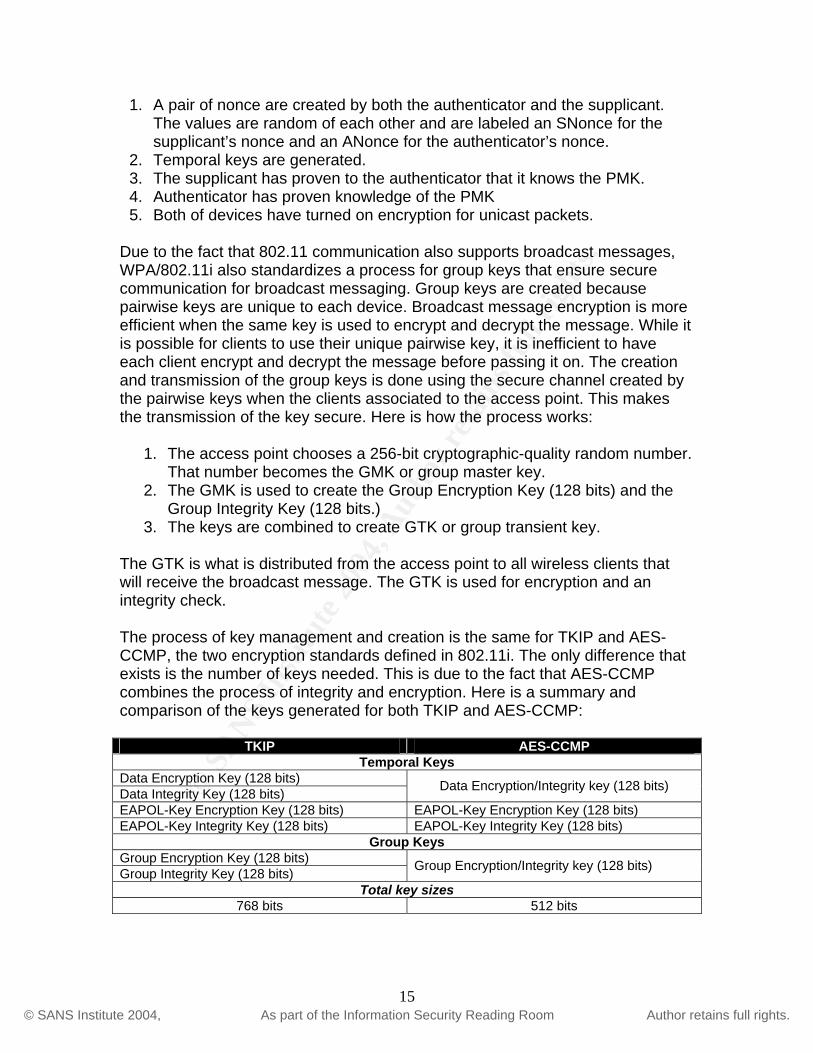
3. The keys are combined to create GTK or group transient key. The GTK is what is distributed from the access point to all wireless clients that will receive the broadcast message. The GTK is used for encryption and an integrity check. The process of key management and creation is the same for TKIP and AES-CCMP, the two encryption standards defined in 802.11i. The only difference that exists is the number of keys needed. This is due to the fact that AES-CCMP combines the process of integrity and encryption. Here is a summary and comparison of the keys generated for both TKIP and AES-CCMP:
TKIP AES-CCMP Temporal Keys
Data Encryption Key (128 bits) Data Integrity Key (128 bits) Data Encryption/Integrity key (128 bits)
EAPOL-Key Encryption Key (128 bits) EAPOL-Key Encryption Key (128 bits) EAPOL-Key Integrity Key (128 bits) EAPOL-Key Integrity Key (128 bits)
Group Keys Group Encryption Key (128 bits) Group Integrity Key (128 bits) Group Encryption/Integrity key (128 bits)
Total key sizes 768 bits 512 bits
15
© S
AN
S In
stitu
te 2
004,
Aut
hor r
etai
ns fu
ll ri
ghts
.Key fingerprint = AF19 FA27 2F94 998D FDB5 DE3D F8B5 06E4 A169 4E46
© SANS Institute 2004, As part of the Information Security Reading Room Author retains full rights.
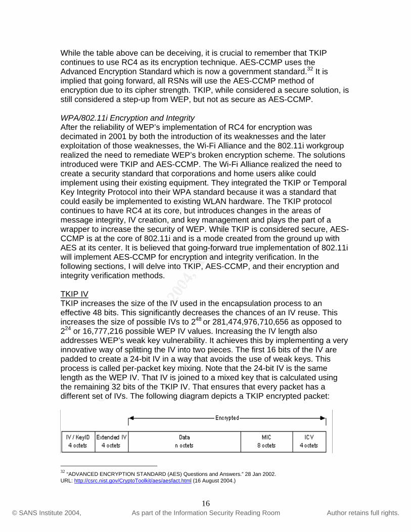
While the table above can be deceiving, it is crucial to remember that TKIP continues to use RC4 as its encryption technique. AES-CCMP uses the Advanced Encryption Standard which is now a government standard.32 It is implied that going forward, all RSNs will use the AES-CCMP method of encryption due to its cipher strength. TKIP, while considered a secure solution, is still considered a step-up from WEP, but not as secure as AES-CCMP. WPA/802.11i Encryption and Integrity After the reliability of WEP’s implementation of RC4 for encryption was decimated in 2001 by both the introduction of its weaknesses and the later exploitation of those weaknesses, the Wi-Fi Alliance and the 802.11i workgroup realized the need to remediate WEP’s broken encryption scheme. The solutions introduced were TKIP and AES-CCMP. The Wi-Fi Alliance realized the need to create a security standard that corporations and home users alike could implement using their existing equipment. They integrated the TKIP or Temporal Key Integrity Protocol into their WPA standard because it was a standard that could easily be implemented to existing WLAN hardware. The TKIP protocol continues to have RC4 at its core, but introduces changes in the areas of message integrity, IV creation, and key management and plays the part of a wrapper to increase the security of WEP. While TKIP is considered secure, AES-CCMP is at the core of 802.11i and is a mode created from the ground up with AES at its center. It is believed that going-forward true implementation of 802.11i will implement AES-CCMP for encryption and integrity verification. In the following sections, I will delve into TKIP, AES-CCMP, and their encryption and integrity verification methods. TKIP IV TKIP increases the size of the IV used in the encapsulation process to an effective 48 bits. This significantly decreases the chances of an IV reuse. This increases the size of possible IVs to 248 or 281,474,976,710,656 as opposed to 224 or 16,777,216 possible WEP IV values. Increasing the IV length also addresses WEP’s weak key vulnerability. It achieves this by implementing a very innovative way of splitting the IV into two pieces. The first 16 bits of the IV are padded to create a 24-bit IV in a way that avoids the use of weak keys. This process is called per-packet key mixing. Note that the 24-bit IV is the same length as the WEP IV. That IV is joined to a mixed key that is calculated using the remaining 32 bits of the TKIP IV. That ensures that every packet has a different set of IVs. The following diagram depicts a TKIP encrypted packet:
32 “ADVANCED ENCRYPTION STANDARD (AES) Questions and Answers.” 28 Jan 2002. URL: http://csrc.nist.gov/CryptoToolkit/aes/aesfact.html (16 August 2004.)
16
© S
AN
S In
stitu
te 2
004,
Aut
hor r
etai
ns fu
ll ri
ghts
.Key fingerprint = AF19 FA27 2F94 998D FDB5 DE3D F8B5 06E4 A169 4E46
© SANS Institute 2004, As part of the Information Security Reading Room Author retains full rights.
As you can see from the above diagram, TKIP adds 12 bytes. The 12 bytes are comprised of the extended IV (4) and the MIC (8.) The MIC is TKIP’s implementation of a message integrity check discussed later. 33
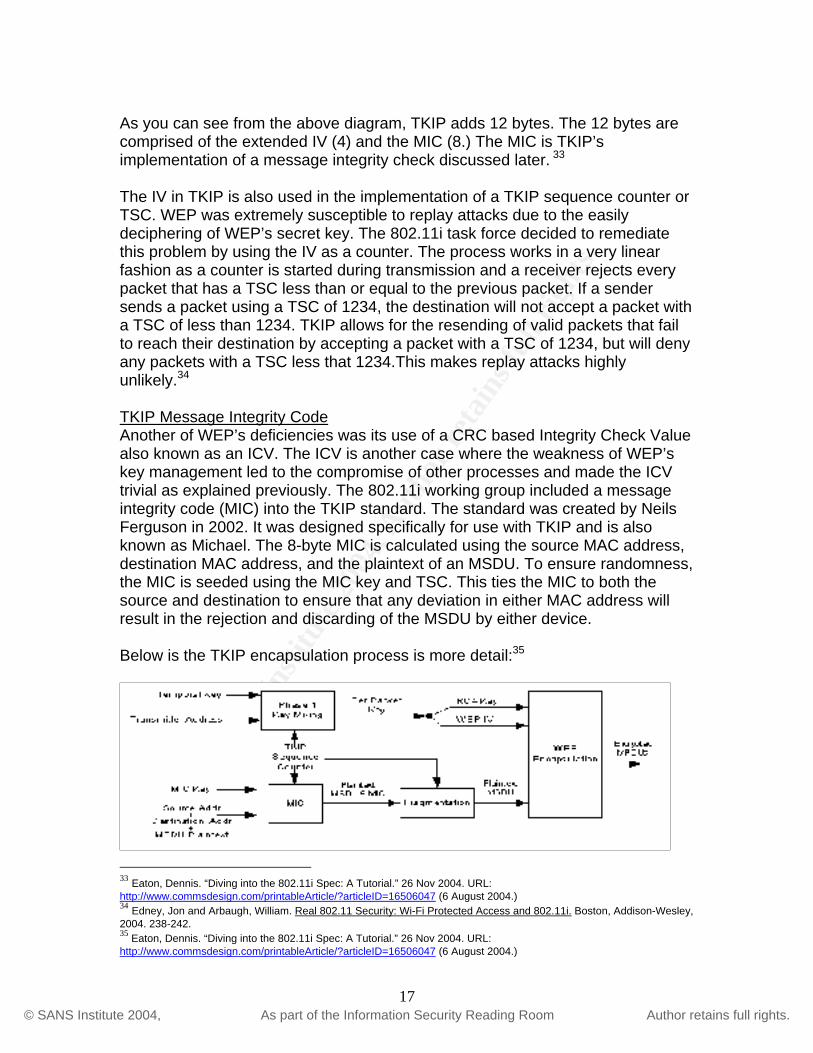
The IV in TKIP is also used in the implementation of a TKIP sequence counter or TSC. WEP was extremely susceptible to replay attacks due to the easily deciphering of WEP’s secret key. The 802.11i task force decided to remediate this problem by using the IV as a counter. The process works in a very linear fashion as a counter is started during transmission and a receiver rejects every packet that has a TSC less than or equal to the previous packet. If a sender sends a packet using a TSC of 1234, the destination will not accept a packet with a TSC of less than 1234. TKIP allows for the resending of valid packets that fail to reach their destination by accepting a packet with a TSC of 1234, but will deny any packets with a TSC less that 1234.This makes replay attacks highly unlikely.34 TKIP Message Integrity Code Another of WEP’s deficiencies was its use of a CRC based Integrity Check Value also known as an ICV. The ICV is another case where the weakness of WEP’s key management led to the compromise of other processes and made the ICV trivial as explained previously. The 802.11i working group included a message integrity code (MIC) into the TKIP standard. The standard was created by Neils Ferguson in 2002. It was designed specifically for use with TKIP and is also known as Michael. The 8-byte MIC is calculated using the source MAC address, destination MAC address, and the plaintext of an MSDU. To ensure randomness, the MIC is seeded using the MIC key and TSC. This ties the MIC to both the source and destination to ensure that any deviation in either MAC address will result in the rejection and discarding of the MSDU by either device. Below is the TKIP encapsulation process is more detail:35
33 Eaton, Dennis. “Diving into the 802.11i Spec: A Tutorial.” 26 Nov 2004. URL: http://www.commsdesign.com/printableArticle/?articleID=16506047 (6 August 2004.) 34 Edney, Jon and Arbaugh, William. Real 802.11 Security: Wi-Fi Protected Access and 802.11i. Boston, Addison-Wesley, 2004. 238-242. 35 Eaton, Dennis. “Diving into the 802.11i Spec: A Tutorial.” 26 Nov 2004. URL: http://www.commsdesign.com/printableArticle/?articleID=16506047 (6 August 2004.)
17

© S
AN
S In
stitu
te 2
004,
Aut
hor r
etai
ns fu
ll ri
ghts
.Key fingerprint = AF19 FA27 2F94 998D FDB5 DE3D F8B5 06E4 A169 4E46
© SANS Institute 2004, As part of the Information Security Reading Room Author retains full rights.
As you can ascertain from the above section on TKIP, the 802.11i working group, in conjunction with the Wi-Fi alliance, created a standard that allowed for the remediation of WEP’s security issues while keeping in mind that the future would allow for the use of more robust security standards. TKIP is considered secure, but due to the fact that it continues to have RC4 at its core, the final 802.11i mandates the use of AES-CCMP. TKIP brought security to existing WLAN customers who were in desperate need of securing their WLAN environments, while RSNs using AES-CCMP will be the future for WLAN implementations.36
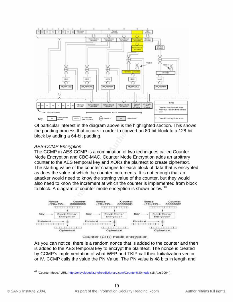
AES-CCMP While TKIP is supported by 802.11i, the implementation of AES-CCMP is mandatory for 802.11i. As you can decipher from the title, AES-CCMP is a mode of AES. It was designed by D. Whiting, N. Ferguson, and R. Housley for implementation in 802.11i.37 The way AES became the algorithm of choice for 802.11i is an interesting story. At the same time that the 802.11i working group was looking for an algorithm to implement in its new WLAN security standard, the U.S. National Institute for Science and Technology38 also know as NIST, was looking for an encryption algorithm to implement as part of their security applications. After holding a competition of sorts, where experts around the world submitted their algorithms, AES was chosen as the standard encryption algorithm. Even though AES can be implemented in sizes of 128-bit, 192-bit, and 256-bit, the only size supported in 802.11i is 128-bit AES. The mode of operation, or CCMP in this case, needed to meet certain criteria to work with AES. Being a block-cipher, AES relies on the fact that it must encrypt and decrypt 128-bit blocks. This means that even if a message contains a length that is not a factor of 128 bits, the mode of operation chosen needed a mechanism to convert blocks of data into128-bit blocks even if it meant inserting arbitrary data to complete the 128-bit block. CCMP accomplishes this by padding the block that doesn’t meet the 128-bit requirement. It pads the block before encryption and discards the padding after decryption due to the fact the padding was not part of the original message. The following diagram shows the encapsulation process for AES-CCMP:39
36 Robinson, Frank. “802.11i and WPA Up Close.” 1 April 2004. URL: http://www.nwc.com/showitem.jhtml?docid=1506ws1 (18 July 2004.) 37 Cam-Winget, Nancy., et al. “IEEE 802.11i Overview.” URL: http://csrc.nist.gov/wireless/S10_802.11i%20Overview-jw1.pdf (21 June 2004.) 38 http://www.nist.gov39 “IEEE Std 802.11i/D3.0.” November 2003. URL: http://www.cs.umd.edu/~mhshin/doc/802.11/802.11i-D3.0.pdf (16 Aug 2004.)
18
© S
AN
S In
stitu
te 2
004,
Aut
hor r
etai
ns fu
ll ri
ghts
.Key fingerprint = AF19 FA27 2F94 998D FDB5 DE3D F8B5 06E4 A169 4E46
© SANS Institute 2004, As part of the Information Security Reading Room Author retains full rights.
Of particular interest in the diagram above is the highlighted section. This shows the padding process that occurs in order to convert an 80-bit block to a 128-bit block by adding a 64-bit padding. AES-CCMP Encryption The CCMP in AES-CCMP is a combination of two techniques called Counter Mode Encryption and CBC-MAC. Counter Mode Encryption adds an arbitrary counter to the AES temporal key and XORs the plaintext to create ciphertext. The starting value of the counter changes for each block of data that is encrypted as does the value at which the counter increments. It is not enough that an attacker would need to know the starting value of the counter, but they would also need to know the increment at which the counter is implemented from block to block. A diagram of counter mode encryption is shown below:40
As you can notice, there is a random nonce that is added to the counter and then is added to the AES temporal key to encrypt the plaintext. The nonce is created by CCMP’s implementation of what WEP and TKIP call their Initialization vector or IV. CCMP calls the value the PN Value. The PN value is 48 bits in length and
40 “Counter Mode.” URL: http://encyclopedia.thefreedictionary.com/Counter%20mode (18 Aug 2004.)
19

© S
AN
S In
stitu
te 2
004,
Aut
hor r
etai
ns fu
ll ri
ghts
.Key fingerprint = AF19 FA27 2F94 998D FDB5 DE3D F8B5 06E4 A169 4E46
© SANS Institute 2004, As part of the Information Security Reading Room Author retains full rights.
is contained in the CCMP header of a message. This value is a counter that is used to create the nonce and seed the counter used for encryption. This ensures that the need for confidentiality is satisfied.41 AES-CCMP Integrity Simply securely encrypting information does not satisfy the need for integrity however. The standard needed a mechanism by which two devices could guarantee that a message was not altered while in transit. That is where CBC-MAC comes in. CBC-MAC basically works by taken the first 128-bit block of data and encrypting it using the AES algorithm. It then uses the ciphertext to XOR the second 128-bit block. This continues until the entire message MIC value is computed. What is created is a 128-bit block message integrity code. We will see later how only the first 64-bits of this block are used as the MIC for a message. The remaining 64 bits are discarded. The chances of forging this MIC value are 1 in 1019 even at a 64-bit size.42 This ensures the integrity of the message in transit. The following diagram depicts the creation of the MIC value using CBC-MAC43:
41 Edney, Jon and Arbaugh, William. Real 802.11 Security: Wi-Fi Protected Access and 802.11i. Boston, Addison-Wesley, 2004. 269-272. 42 Edney, Jon and Arbaugh, William. Real 802.11 Security: Wi-Fi Protected Access and 802.11i. Boston, Addison-Wesley, 2004. 273. 43 “IEEE Std 802.11i/D3.0.” November 2003. URL: http://www.cs.umd.edu/~mhshin/doc/802.11/802.11i-D3.0.pdf (16 Aug 2004.)
20

© S
AN
S In
stitu
te 2
004,
Aut
hor r
etai
ns fu
ll ri
ghts
.Key fingerprint = AF19 FA27 2F94 998D FDB5 DE3D F8B5 06E4 A169 4E46
© SANS Institute 2004, As part of the Information Security Reading Room Author retains full rights.
This diagram shows how the PN is used to create the MIC_IV that seeds the AES encryption to encrypt the first block of data and continues to use the XORed values of the previous blocks to encrypted the proceeding blocks. WPA/802.11i Summary I don’t think that anyone can contest that WPA and 802.11i are leaps and bounds more secure and scalable than WEP. This paper started out by referencing the CIA triad and WEP’s failure to satisfy any of the requirements that comprise the triad. I believe that the combination of 802.1x authentication/key management, TKIP, and AES-CCMP have satisfied the CIA triad. The confidentiality is provided by TKIP encryption and will continue to be provided by AES-CCMP encryption. Secondly, the integrity is provided by both MIC implementations in TKIP and AES-CCMP. Finally, the availability is provided by 802.1x. While these technologies have remediated WEP’s deficiencies, they are not without their critics. 802.11i has come under fire because of its requirement of AES. At the time of this writing, in order to implement 802.11i using AES-CCMP, most of the existing access points in production need to be replaced. After the standard was ratified, vendors have begun to promise software upgrades for clients and have begun production of AES capable access points. I tend to disagree with most individuals that say that the requirements for 802.11i are stringent. That is what has been missing from WLAN security since its introduction. The responsibility of securing WLANs falls on corporations now because the standard is ratified and the guidelines are there to follow. There is speculation that corporations wishing to do business with the U.S. government will need to comply with 802.11i when using wireless communication.44
In concluding, while I think that adoption of RSNs may be slow due to the costs of hardware replacement and a lowly technology spending cycle, I feel the IEEE has done a masterful job of creating this standard. I do feel that many, if not all corporations, will begin to at a minimum, use TKIP and certain aspects of 802.11i. Our corporate WLANs are just becoming to crucial to not take the time to secure them. I just hope that WLAN administrators can remember a quote I found during my research. “One of the mistakes that designers can make when evaluating the individual security elements discussed above is to consider them as individual silos. It’s important to understand that all the 802.11i pieces described above work together to form an overall security system. Taken individually and out of context of the overall system, any single piece could be shown to have security weaknesses.”45 That was written by Dennis Eaton of Intersil in reference to the entire 802.11i process and the importance of what individuals and corporations are now beginning to realize; security is a process
44 Loeb, Larry. “Roaming charges: Are you ready for 802.11i?” 24 Feb 2004. URL: http://www-106.ibm.com/developerworks/wireless/library/wi-roam19.html (5 Mar 2004.) 45 Eaton, Dennis. “Diving into the 802.11i Spec: A Tutorial.” 26 Nov 2004. URL: http://www.commsdesign.com/printableArticle/?articleID=16506047 (6 August 2004.)
21

© S
AN
S In
stitu
te 2
004,
Aut
hor r
etai
ns fu
ll ri
ghts
.Key fingerprint = AF19 FA27 2F94 998D FDB5 DE3D F8B5 06E4 A169 4E46
© SANS Institute 2004, As part of the Information Security Reading Room Author retains full rights.
and it encompasses many different resources. It is a process that requires hardware, software, and most importantly the right people.
22
© S
AN
S In
stitu
te 2
004,
Aut
hor r
etai
ns fu
ll ri
ghts
.Key fingerprint = AF19 FA27 2F94 998D FDB5 DE3D F8B5 06E4 A169 4E46
© SANS Institute 2004, As part of the Information Security Reading Room Author retains full rights.
References
“ADVANCED ENCRYPTION STANDARD (AES) Questions and Answers.” 28 Jan 2002. URL: http://csrc.nist.gov/CryptoToolkit/aes/aesfact.html (16 August 2004.) Arbaugh, William A., Shankar, Narendar, Wan, Justin Y.C. “Your 802.11 Wireless Network has No Clothes.” 30 March 2001. URL: http://www.cs.umd.edu/~waa/wireless.pdf. (19 July 2004.) Cam-Winget, Nancy., et al. “IEEE 802.11i Overview.” URL: http://csrc.nist.gov/wireless/S10_802.11i%20Overview-jw1.pdf (21 June 2004.) “Counter Mode.” URL: http://encyclopedia.thefreedictionary.com/Counter%20mode (18 Aug 2004.) Eaton, Dennis. “Diving into the 802.11i Spec: A Tutorial.” 26 Nov 2004. URL: http://www.commsdesign.com/printableArticle/?articleID=16506047 (6 August 2004.) Edney, Jon and Arbaugh, William. Real 802.11 Security: Wi-Fi Protected Access and 802.11i. Boston, Addison-Wesley, 2004 Fleishman, Glenn. “Caring About 802.11i.” 25 June 2004. URL: http://www.wifinetnews.com/archives/003939.html. (20 Aug 2004.) Fluhrer, Scott, Mantin, Itsik, Shamir, Adi. “Weaknesses in the Key Scheduling Algorithm of RC4” 2001. URL: http://www.drizzle.com/~aboba/IEEE/rc4_ksaproc.pdf (25 June 2004.) Gast, Matthew. “Wireless LAN Security: A Short History.” 19 April 2002. URL: http://www.oreillynet.com/lpt/a/1728 (26 June 2004.) “IEEE Std 802.11i/D3.0.” November 2003. URL: http://www.cs.umd.edu/~mhshin/doc/802.11/802.11i-D3.0.pdf (16 Aug 2004.) Jason Liu, “The Insecurity of WEP.” URL: http://www.cse.ogi.edu/class/cse525/summaries/10/TheInsecurityofWEP.ppt (16 June 2004.) Loeb, Larry. “Roaming charges: Are you ready for 802.11i?” 24 Feb 2004. URL: http://www-106.ibm.com/developerworks/wireless/library/wi-roam19.html (5 Mar 2004.)
23
© S
AN
S In
stitu
te 2
004,
Aut
hor r
etai
ns fu
ll ri
ghts
.Key fingerprint = AF19 FA27 2F94 998D FDB5 DE3D F8B5 06E4 A169 4E46
© SANS Institute 2004, As part of the Information Security Reading Room Author retains full rights.
Robinson, Frank. “802.11i and WPA Up Close.” 1 April 2004. URL: http://www.nwc.com/showitem.jhtml?docid=1506ws1 (18 July 2004.) Walker, Jess R. “IEEE P802.11 Wireless LANs: Unsafe at any key size; An analysis of the WEP encapsulation.” 27 October 2000. URL: http:// www.dis.org/wl/pdf/unsafe.pdf (23 June 2004.) “Wireless LAN: Security – WEP.” 30 June 2002. URL: http://www.esat.kuleuven.ac.be/~h239/reports/2001/wlan/security.php (26 June 2004.) “WLAN Solutions – 802.1x and Bluesocket.” URL: http://www.bluesocket.com/solutions/802.1x-Feature-Brief.pdf (6 August 2004.)
24