wireless communication laboratory brochure2 - uet … · design and implementation of fractal...
TRANSCRIPT
Electrical Engineering Department Electrical Engineering Department Electrical Engineering Department Electrical Engineering Department
University of Engineering and Technology Lahore University of Engineering and Technology Lahore University of Engineering and Technology Lahore University of Engineering and Technology Lahore
WIRELESS
Electrical Engineering Department Electrical Engineering Department Electrical Engineering Department Electrical Engineering Department
University of Engineering and Technology Lahore University of Engineering and Technology Lahore University of Engineering and Technology Lahore University of Engineering and Technology Lahore
IRELESS COMMUNICATION
LABORATORY
Electrical Engineering Department Electrical Engineering Department Electrical Engineering Department Electrical Engineering Department
University of Engineering and Technology Lahore University of Engineering and Technology Lahore University of Engineering and Technology Lahore University of Engineering and Technology Lahore
OMMUNICATION
LAB OBJECTIVE:
We are living in the information age and wireless communication networks
provide the critical infrastructure for anytime, anywhere connectivity to information. Advances
in computing, communication and sensing technologies are enabling unprecedented new ways
in which information can be gathered, processed and shared wirelessly. However, the rapid
proliferation of a dazzling array of networks of heterogeneous wireless communication devices
poses immediate and significant technical challenges. One of the biggest challenges is the
efficient use of the shared and essentially limited radio frequency spectrum over which
wireless devices communicate. On the one hand, wireless technology is racing ahead and
enabling a broad array of wireless networks, including cellular, ad hoc, mesh, local area,
personal and sensor networks, supporting an equally rich array of multimedia applications such
as voice, data, images, and video. In addition, practicing engineers, computer specialists, and
managers have to re-educate themselves in the area of wireless technology.
The University of Engineering and Technology Lahore recognized the need to
prepare its students for careers in wireless and successfully developed one of the first
instructional Wireless Communication laboratories inception in 1998, with a funding of
$600,000, in collaboration with Higher Education Commission (HEC). The laboratory has
provided many students during the past decade with the opportunity to acquire both in-depth
theoretical understanding and hands-on experience in this rapidly growing discipline. Since its
inception the Wireless Communications Research Laboratory at the University of Engineering
and Technology has been investigating a wide range of problems in the basic theory and
practical design strategies for wireless communication systems and networks.
The lab aims at achieving the following objectives :
� Provision of the state of the art Facilities for Research Projects in Wireless
Communication Field.
� Developing technical solution to various Wireless Communication Related Projects
� Developing Trained Personals for educating and training for upcoming graduates in
wireless communication.
The lab facility can be used to investigate the problems in the following fields:
� Wireless Channel Modeling in Time, Frequency and Space.
� Communication over Dispersive Wireless Channels.
� Cognitive Wireless Networks
Wireless Communication Lab Project Director:
Dr. Noor Muhammad SheikhEngineering at UET Lahore. He did his PhD in 1979 from University of Engineering & Technology, Lahore. His research interests include Communication System, Digital Communication, Digital Signal Processing, Signal and System, Detection and Estimation and Communication Theory. He has a large number of publications in the above area in Intand Conferences.
Dr Mohammad Saleem Mianof Electrical Engineering UET Lahore, Pakistan. He completed his Doctorate from University of Manchester U. K. in 1998. He has a vast experience of working with the modern trend and technologies in the area of Digital Signal Processing and has a number of International Publications in this area. He worked in a DSP research group for audcompression in University of Manchester UK. 1993
He has Supervised theSimulation and Hardware Implementation of X band Transceiver”Wireless Communication Lab.
Wireless Communication Lab Director:
Dr. Muhammad Imran SheikhEngineering Department, UET Lahore. He completed his Doctorate in wireless communications from The University of Birmingham, Birmingham, U.K. in 1997. He is a director of DSP and Wireless Communication Lab and establishment of the Laboratory. The laboratory provides an integrated environment for the development of a variety of wireless communication systems. His research interests include Antenna Theory Analysis and Design, Array Signal Processing, Digital Signal Processing, Wireless Communication Systems, Information Theory and Design
Researcher’s :
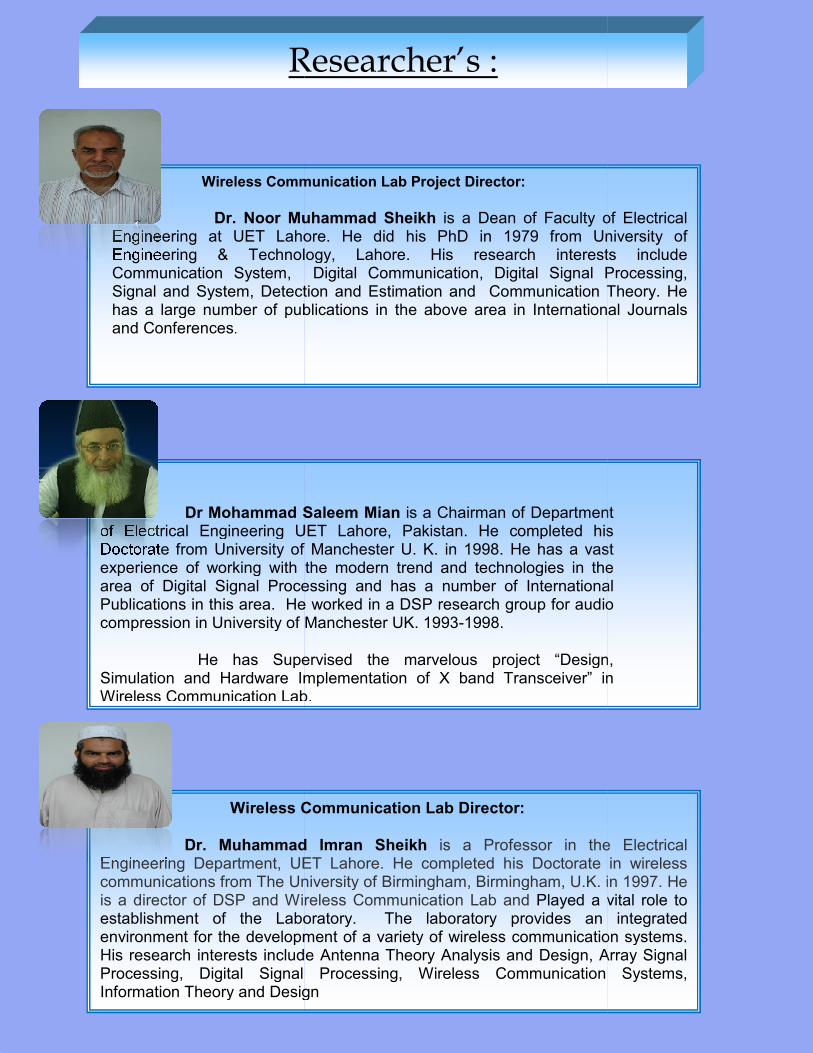
Wireless Communication Lab Project Director:
Dr. Noor Muhammad Sheikh is a Dean of Faculty of Electrical Engineering at UET Lahore. He did his PhD in 1979 from University of
echnology, Lahore. His research interests include Communication System, Digital Communication, Digital Signal Processing, Signal and System, Detection and Estimation and Communication Theory. He has a large number of publications in the above area in International Journals
Dr Mohammad Saleem Mian is a Chairman of Department of Electrical Engineering UET Lahore, Pakistan. He completed his
versity of Manchester U. K. in 1998. He has a vast experience of working with the modern trend and technologies in the area of Digital Signal Processing and has a number of International Publications in this area. He worked in a DSP research group for audio compression in University of Manchester UK. 1993-1998.
He has Supervised the marvelous project “Design,Simulation and Hardware Implementation of X band Transceiver” in Wireless Communication Lab.
Wireless Communication Lab Director:
Dr. Muhammad Imran Sheikh is a Professor in the Electrical Engineering Department, UET Lahore. He completed his Doctorate in wireless
The University of Birmingham, Birmingham, U.K. in 1997. He is a director of DSP and Wireless Communication Lab and Played a vital role to establishment of the Laboratory. The laboratory provides an integrated environment for the development of a variety of wireless communication systems. His research interests include Antenna Theory Analysis and Design, Array Signal
g, Digital Signal Processing, Wireless Communication Systems, Information Theory and Design
Researcher’s :
is a Dean of Faculty of Electrical Engineering at UET Lahore. He did his PhD in 1979 from University of
echnology, Lahore. His research interests include Communication System, Digital Communication, Digital Signal Processing, Signal and System, Detection and Estimation and Communication Theory. He
ernational Journals
is a Chairman of Department of Electrical Engineering UET Lahore, Pakistan. He completed his
versity of Manchester U. K. in 1998. He has a vast experience of working with the modern trend and technologies in the area of Digital Signal Processing and has a number of International
io
project “Design, in
is a Professor in the Electrical Engineering Department, UET Lahore. He completed his Doctorate in wireless
The University of Birmingham, Birmingham, U.K. in 1997. He vital role to
establishment of the Laboratory. The laboratory provides an integrated environment for the development of a variety of wireless communication systems. His research interests include Antenna Theory Analysis and Design, Array Signal
g, Digital Signal Processing, Wireless Communication Systems,
The Wireless Communication Lab is equipped with
and software for doing advanced research and development work in Wireless
Communication field.
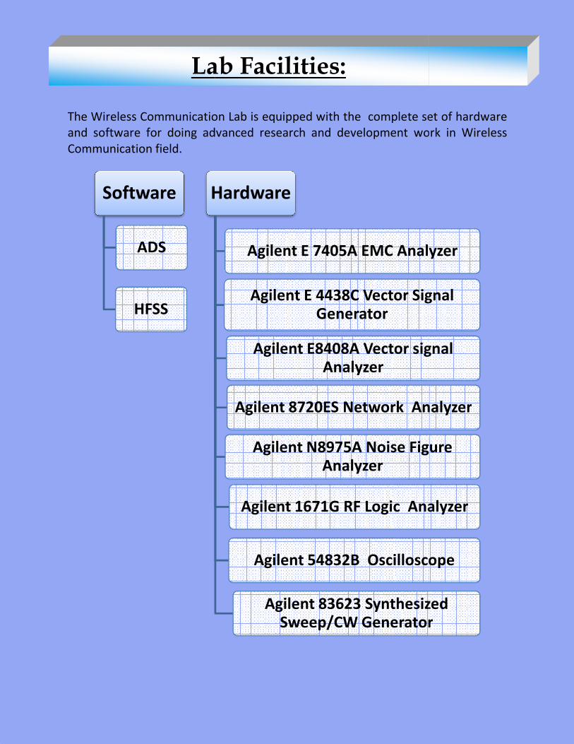
Software
ADS
HFSS
Hardware
Lab Facilities
The Wireless Communication Lab is equipped with the complete set of hardware
for doing advanced research and development work in Wireless
Hardware
Agilent E 7405A EMC Analyzer
Agilent E 4438C Vector Signal Generator
Agilent E8408A Vector signal Analyzer
Agilent 8720ES Network Analyzer
Agilent N8975A Noise Figure Analyzer
Agilent 1671G RF Logic Analyzer
Agilent 54832B Oscilloscope
Agilent 83623 Synthesized Sweep/CW Generator
Lab Facilities:
complete set of hardware
for doing advanced research and development work in Wireless
Agilent E 7405A EMC Analyzer
Agilent E 4438C Vector Signal
Agilent E8408A Vector signal
Agilent 8720ES Network Analyzer
Agilent N8975A Noise Figure
Agilent 1671G RF Logic Analyzer
Agilent 54832B Oscilloscope
Agilent 83623 Synthesized Sweep/CW Generator
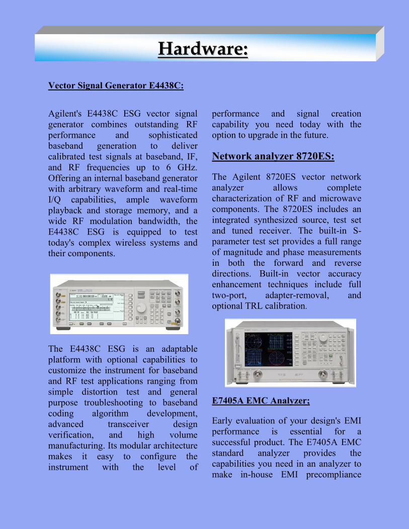
Vector Signal Generator E4438C:
Agilent's E4438C ESG vector signal
generator combines outstanding RF
performance and sophisticated
baseband generation to deliver
calibrated test signals at baseband, IF,
and RF frequencies up to 6 GHz.
Offering an internal baseband generator
with arbitrary waveform and real-time
I/Q capabilities, ample waveform
playback and storage memory, and a
wide RF modulation bandwidth, the
E4438C ESG is equipped to test
today's complex wireless systems and
their components.
The E4438C ESG is an adaptable
platform with optional capabilities to
customize the instrument for baseband
and RF test applications ranging from
simple distortion test and general
purpose troubleshooting to baseband
coding algorithm development,
advanced transceiver design
verification, and high volume
manufacturing. Its modular architecture
makes it easy to configure the
instrument with the level of
performance and signal creation
capability you need today with the
option to upgrade in the future.
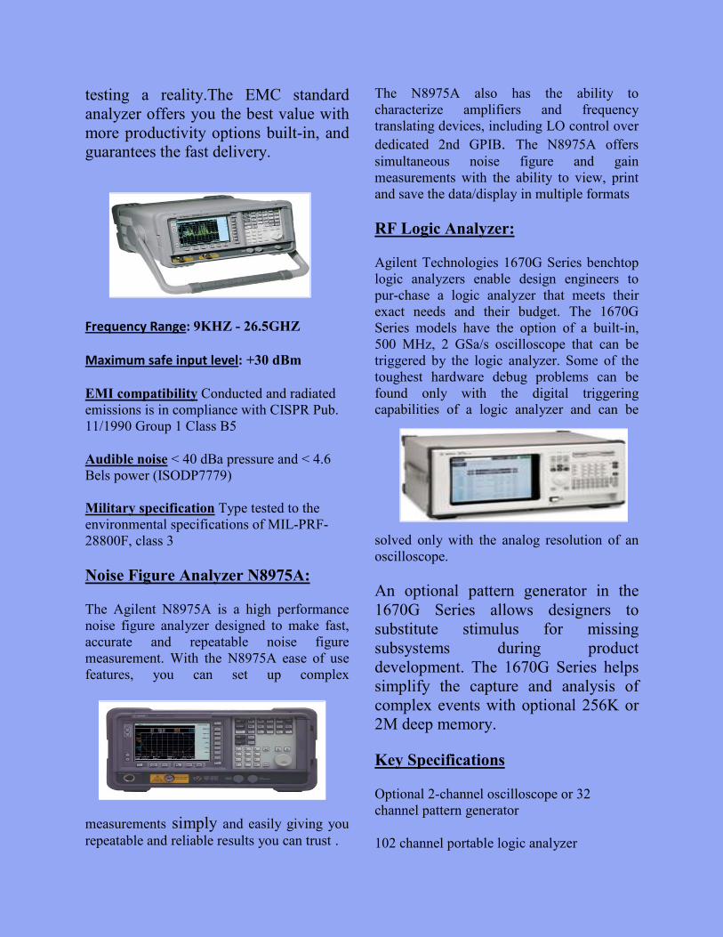
Network analyzer 8720ES:
The Agilent 8720ES vector network
analyzer allows complete
characterization of RF and microwave
components. The 8720ES includes an
integrated synthesized source, test set
and tuned receiver. The built-in S-
parameter test set provides a full range
of magnitude and phase measurements
in both the forward and reverse
directions. Built-in vector accuracy
enhancement techniques include full
two-port, adapter-removal, and
optional TRL calibration.
E7405A EMC Analyzer;
Early evaluation of your design's EMI
performance is essential for a
successful product. The E7405A EMC
standard analyzer provides the
capabilities you need in an analyzer to
make in-house EMI precompliance
HHaarrddwwaarree::
testing a reality.The EMC standard
analyzer offers you the best value with
more productivity options built-in, and
guarantees the fast delivery.
Frequency Range: 9KHZ - 26.5GHZ
Maximum safe input level: +30 dBm
EMI compatibility Conducted and radiated
emissions is in compliance with CISPR Pub.
11/1990 Group 1 Class B5
Audible noise < 40 dBa pressure and < 4.6
Bels power (ISODP7779)
Military specification Type tested to the
environmental specifications of MIL-PRF-
28800F, class 3
Noise Figure Analyzer N8975A:
The Agilent N8975A is a high performance
noise figure analyzer designed to make fast,
accurate and repeatable noise figure
measurement. With the N8975A ease of use
features, you can set up complex
measurements simply and easily giving you
repeatable and reliable results you can trust .
The N8975A also has the ability to
characterize amplifiers and frequency
translating devices, including LO control over
dedicated 2nd GPIB. The N8975A offers
simultaneous noise figure and gain
measurements with the ability to view, print
and save the data/display in multiple formats
RF Logic Analyzer:
Agilent Technologies 1670G Series benchtop
logic analyzers enable design engineers to
pur-chase a logic analyzer that meets their
exact needs and their budget. The 1670G
Series models have the option of a built-in,
500 MHz, 2 GSa/s oscilloscope that can be
triggered by the logic analyzer. Some of the
toughest hardware debug problems can be
found only with the digital triggering
capabilities of a logic analyzer and can be
solved only with the analog resolution of an
oscilloscope.
An optional pattern generator in the
1670G Series allows designers to
substitute stimulus for missing
subsystems during product
development. The 1670G Series helps
simplify the capture and analysis of
complex events with optional 256K or
2M deep memory.
Key Specifications
Optional 2-channel oscilloscope or 32
channel pattern generator
102 channel portable logic analyzer
500 MHz timing speed
Experiments are designed in order to cover the following
topics
� Analog and Digital Modulation
� Noise Figure Measurement
� Scattering Parameters Measurement
� Raised Cosine Filter Characteristic
� Voltage Standing Wave Ratio Measurement
� Smith Chart Demonstration
Experiment # 1
Measurement of S Parameters, S11 (input
Reflection Coefficient), S22 (output Reflection
Coefficient), S12 (return Loss), S21 (Forward
Gain) of RF & Microwave Devices (e.g.
Amplifiers, Filters, Power Dividers, Couplers))))
Experiment # 2Experiment # 2Experiment # 2Experiment # 2
Measurement of Voltage Standing Wave Ratio
(VSWR) of RF & Microwave Devices.
Courses Taught:
The Major courses related to this lab are mentioned below
(1) MICROWAVE (2) DIGITAL COMMUNICATION
(3) Electromagnetic Theory (4) Transmission Lines and Antenna’s
List of Experiments:
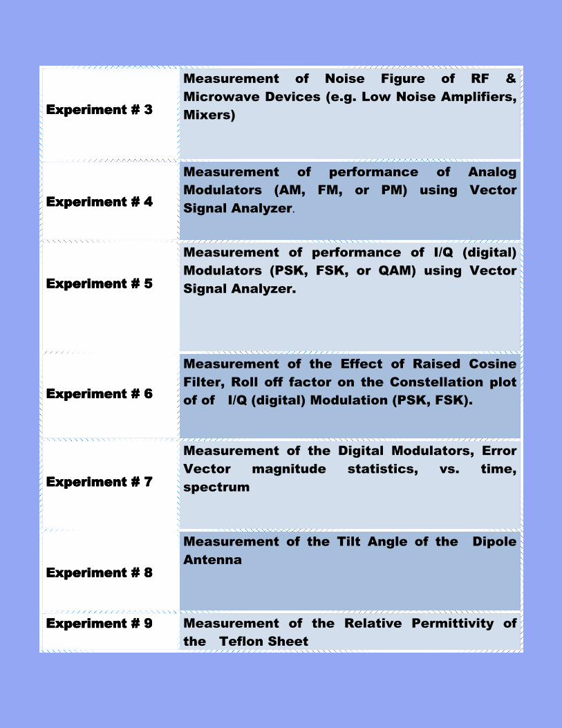
Experiment # 3 Experiment # 3 Experiment # 3 Experiment # 3
Measurement of Noise Figure of RF &
Microwave Devices (e.g. Low Noise Amplifiers,
Mixers)
Experiment # 4Experiment # 4Experiment # 4Experiment # 4
Measurement of performance of Analog
Modulators (AM, FM, or PM) using Vector
Signal Analyzer.
Experiment # 5Experiment # 5Experiment # 5Experiment # 5
Measurement of performance of I/Q (digital)
Modulators (PSK, FSK, or QAM) using Vector
Signal Analyzer.
Experiment # 6Experiment # 6Experiment # 6Experiment # 6
Measurement of the Effect of Raised Cosine
Filter, Roll off factor on the Constellation plot
of of I/Q (digital) Modulation (PSK, FSK).
Experiment # 7Experiment # 7Experiment # 7Experiment # 7
Measurement of the Digital Modulators, Error
Vector magnitude statistics, vs. time,
spectrum
Experiment # 8Experiment # 8Experiment # 8Experiment # 8
Measurement of the Tilt Angle of the Dipole
Antenna
Experiment # 9Experiment # 9Experiment # 9Experiment # 9 Measurement of the Relative Permittivity of
the Teflon Sheet

The facilities available in the lab provide excellent opportunities to the undergraduate students to
enhance their understanding of Wireless Communication
and working on various projects. These facilities are also q
students to carry out their research. Some of the recently completed projects are as under
Simulation and Hardware Simulation and Hardware Simulation and Hardware Simulation and Hardware
Implementation of S Band Implementation of S Band Implementation of S Band Implementation of S Band
Transceiver:Transceiver:Transceiver:Transceiver:
This transceiver is designed for Satellite
and terrestrial microwave links as well as
for Wireless LAN and Bluetooth
applications in 2.4 to 2.5 GHz range. It is
a front end transceiver module. In the
transmitter part, it takes IF signal centered
at 70MHz and up-converts it to a
frequency of 2.45 GHz along with
filtering and amplification of the signal so
that it can be sent in air or space. In the
receiver part, it receives the signal at 2.45
GHz from the antenna, amplifies it and
then down-converts it to IF frequency of
70MHz and then this signal can be fed to
demodulator and further to a data
processing module. ADS (Advanced
Design System) simulation tool by
Agilent has been used for design of the
system, PCAD and Gerber softwares are
used for designing Layouts of PCBs,
while CircuitCam and BoardMaster
softwares are used for etching of PCBs on
LPKF CNC milling machine.
Research Projects:
facilities available in the lab provide excellent opportunities to the undergraduate students to
ance their understanding of Wireless Communication concepts by performing experiments
and working on various projects. These facilities are also quite conducive for the graduate
students to carry out their research. Some of the recently completed projects are as under
DesignDesignDesignDesign and Implementation and Implementation and Implementation and Implementation
of Orthomode Transduceof Orthomode Transduceof Orthomode Transduceof Orthomode Transduce
An orthomode transducer
duct component of the class of microwave
circulators. It is commonly referred to as an
OMT.Such device may be part of a
antenna feed. Orthomode transducers serve
either to combine or to separate two
microwave signal paths. One of the paths
forms the uplink, which is transmitted over
the same waveguide as the received signal
path or downlink path. For
the transmission and reception pat
90° to each other.
A much simpler approach
OMT might be to arrange 4 planar probes
symmetrically in a squa
waveguide.Electric fields generated by
opposite probes driven 180 degrees out of
phase should couple to the TE11 waveguide
mode. By symmetry, orthogonal pairs of
probes should be uncoupled
In this Project HFSS software is used for
designing and Simulating the structure of
Orthomode Transducer.
Simulation and Hardware Simulation and Hardware Simulation and Hardware Simulation and Hardware
Implementation of S Band Implementation of S Band Implementation of S Band Implementation of S Band
This transceiver is designed for Satellite
and terrestrial microwave links as well as
Wireless LAN and Bluetooth
applications in 2.4 to 2.5 GHz range. It is
a front end transceiver module. In the
transmitter part, it takes IF signal centered
converts it to a
frequency of 2.45 GHz along with
signal so
that it can be sent in air or space. In the
receiver part, it receives the signal at 2.45
GHz from the antenna, amplifies it and
converts it to IF frequency of
70MHz and then this signal can be fed to
demodulator and further to a data
processing module. ADS (Advanced
Design System) simulation tool by
Agilent has been used for design of the
system, PCAD and Gerber softwares are
used for designing Layouts of PCBs,
while CircuitCam and BoardMaster
softwares are used for etching of PCBs on
Research Projects:
facilities available in the lab provide excellent opportunities to the undergraduate students to
concepts by performing experiments
cive for the graduate
students to carry out their research. Some of the recently completed projects are as under.
and Implementation and Implementation and Implementation and Implementation
of Orthomode Transduceof Orthomode Transduceof Orthomode Transduceof Orthomode Transducerrrr::::
orthomode transducer is a microwave
duct component of the class of microwave
circulators. It is commonly referred to as an
.Such device may be part of a VSAT
Orthomode transducers serve
either to combine or to separate two
microwave signal paths. One of the paths
, which is transmitted over
as the received signal
path. For VSAT modems
the transmission and reception paths are at
A much simpler approach for designing
t be to arrange 4 planar probes
symmetrically in a square or round
fields generated by
opposite probes driven 180 degrees out of
phase should couple to the TE11 waveguide
mode. By symmetry, orthogonal pairs of
probes should be uncoupled
In this Project HFSS software is used for
designing and Simulating the structure of
rthomode Transducer.
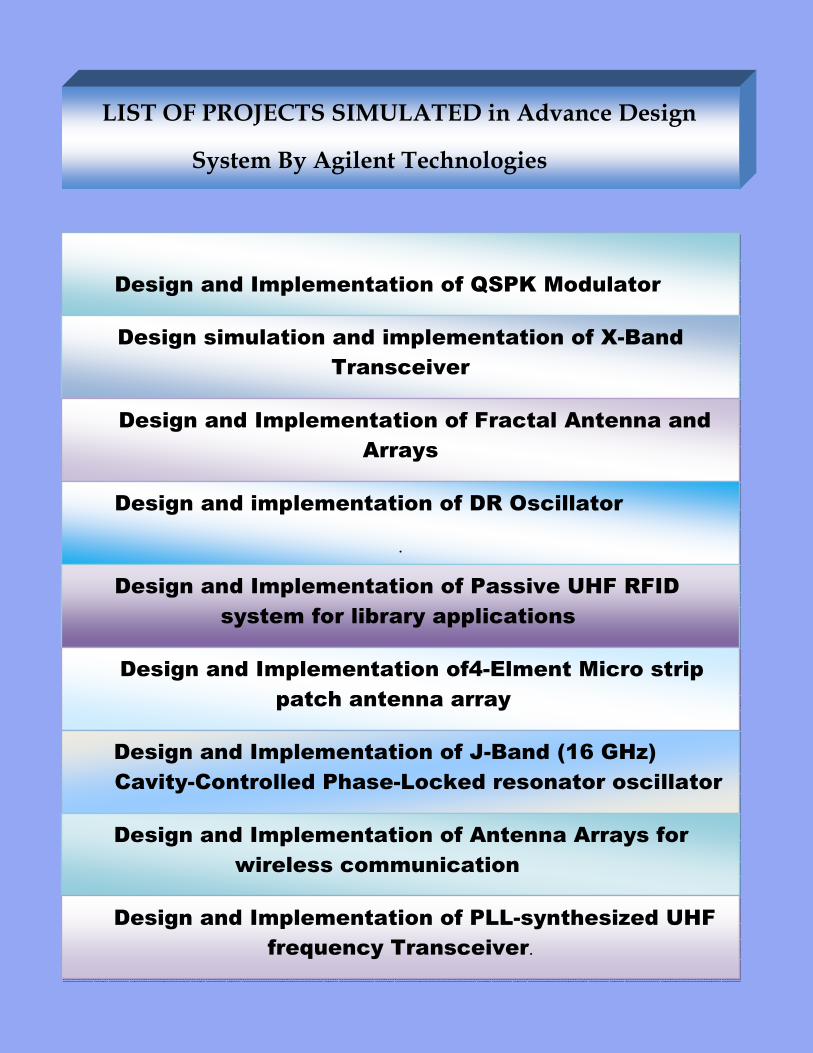
LIST OF PROJECTS SIMULATED in Advance Design
System By Agilent Technologies
Design and Implementation of QSPK Modulator
Design simulation and implementation of X-Band
Transceiver
Design and Implementation of Fractal Antenna and
Arrays
Design and implementation of DR Oscillator
.
Design and Implementation of Passive UHF RFID
system for library applications
Design and Implementation of4-Elment Micro strip
patch antenna array
Design and Implementation of J-Band (16 GHz)
Cavity-Controlled Phase-Locked resonator oscillator
Design and Implementation of Antenna Arrays for
wireless communication
Design and Implementation of PLL-synthesized UHF
frequency Transceiver.
Testing Facilities:
Wireless Communication Lab provides Electromagnetic Compatibility (EMC) testing
Facility to different industries .
Conducted emissions:
Test for noise or interference placed on power or data lines by coupling the E7405A
instrument to the power or data line through a line impedance stabilization network
(LISN) device or absorbing clamp.
Radiated emissions :
When combined with a broadband antenna, the E7405A provides the capabilities to
check for radiated emissions coming from your DUT. This is best done in an area that is
free from reflective objects such as an open area or EMI chamber.
“Efficient Implementation of Deterministic 3-D Ray tracing model to predict propagation losses in Indoor Environments”
Proceedings of the “Thirteenth IEEE International Symposium on Personal, Indoor and Mobile Radio Comms, (PIMRC 2002)”, Sept 15 – 18, 2002, Lisbon, Portugal
“Improved propagation prediction model for wireless channels using impedance diffraction coefficients” Proceedings of the “Fourth IEEE National Multi Topic Conference, (INMIC 2000)”, September 10 –11, 2000, Marriott Hotel, Islamabad
“Error Characterization for ray-optical technique employing perfectly conducting wedges”
Proceedings of the “Fifth IEEE National Multi-Topic Conference, (INMIC 2001)”, December 28-30, 2001, LUMS, Lahore
List Of Publications:
Future
The future plan is to build and establish
Communication Lab. An RF Anechoic C
electromagnetic waves, from the internal surfaces
chamber, the equipment under test receive RF signals from the signal source, not
reflected from another part of the chamber. This ensures the integrity of the testing
being conducted. Furthermore, the shielding of the chambe
equipment located outside of the chamber.
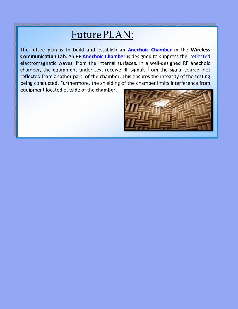
Future PLAN:
The future plan is to build and establish an Anechoic Chamber in the
Anechoic Chamber is designed to suppress the
electromagnetic waves, from the internal surfaces. In a well-designed RF anechoic
chamber, the equipment under test receive RF signals from the signal source, not
of the chamber. This ensures the integrity of the testing
being conducted. Furthermore, the shielding of the chamber limits interference from
equipment located outside of the chamber.
in the Wireless
suppress the reflected
designed RF anechoic
chamber, the equipment under test receive RF signals from the signal source, not
of the chamber. This ensures the integrity of the testing
r limits interference from