wireless lan board - matrix tsl · wireless lan board. ... serving html and javascript compatible...
TRANSCRIPT
www.matrixtsl.com
Wireless LAN board
EB069

2 Copyright © Matrix Technology Solutions Ltd.
Contents
About this document 3Board layout 3General information 4Circuit description 4Protective cover 5Circuit diagram 6

3 Copyright © Matrix Technology Solutions Ltd.
About this document
This document concerns the EB069 E-blocks Wireless LAN board.
1. Trademarks and copyrightPIC and PICmicro are registered trademarks of Arizona Microchip Inc. E-blocks is a trademark of Matrix Technology Solutions Ltd.
2. DisclaimerThe information provided within this document is correct at the time of going to press. Matrix TSL reserves the right to change specifications from time to time.
3. Testing this productIt is advisable to test the product upon receiving it to ensure it works correctly. Matrix provides test procedures
• How to get started with E-blocks - if you are new to E-blocks and wish to learn how to use them from the beginning there are resources available to help.
• Relevant software and hardware that allow you to use your E-blocks product better.
• Example files and programs.• Ways to get technical support for your product, either
via the forums or by contacting us directly.
for all E-blocks, which can be found in the Support section of the website.
4. Product supportIf you require support for this product then please visit the Matrix website, which contains many learning resources for the E-blocks series. On our website you will find:
Board layout
1
1. 9-way downstream D-type connector2. Patch system3. Switch mode voltage inductor4. +V input voltage screw terminal5. Switch mode voltage controller
2
3 4
5
6
87 10
9
6. Logic level voltage shifter7. Wireless LAN module8. Power LED9. Network status LED10. PCB antenna
Signal connections using the patch system.
Signal A (16F88) B (16F877A) Patch
Reset Bit 3 Bit 3 Patch
Trigger Bit 4 Bit 1 Patch
Clear to send (CTS) Bit 1 Bit 4 Patch
Request to send (RTS) Bit 0 Bit 0 Patch
Microcontroller transmit (TX) Bit 5 Bit 6 Patch
Microcontroller receive (RX) Bit 2 Bit 7 Patch
Copyright © Matrix Technology Solutions Ltd.4
General information
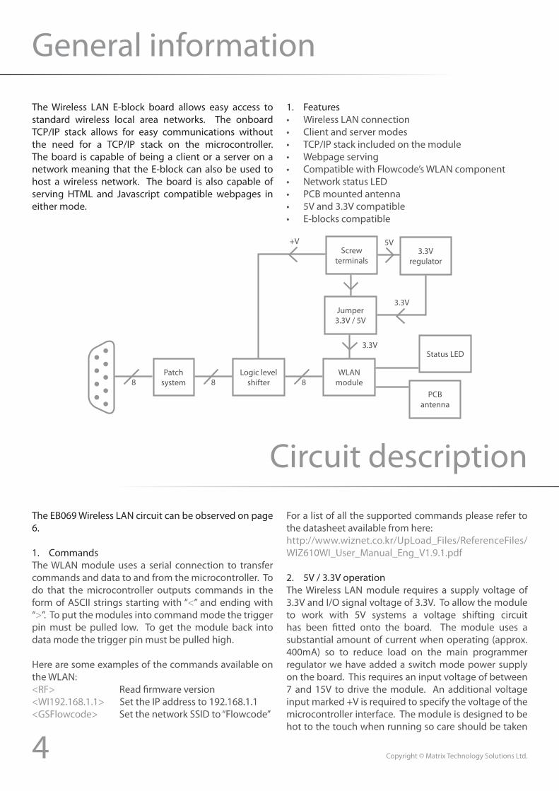
The Wireless LAN E-block board allows easy access to standard wireless local area networks. The onboard TCP/IP stack allows for easy communications without the need for a TCP/IP stack on the microcontroller. The board is capable of being a client or a server on a network meaning that the E-block can also be used to host a wireless network. The board is also capable of serving HTML and Javascript compatible webpages in either mode.
1. Features• Wireless LAN connection• Client and server modes• TCP/IP stack included on the module• Webpage serving• Compatible with Flowcode’s WLAN component• Network status LED• PCB mounted antenna• 5V and 3.3V compatible• E-blocks compatible
Circuit description
The EB069 Wireless LAN circuit can be observed on page 6.
1. CommandsThe WLAN module uses a serial connection to transfer commands and data to and from the microcontroller. To do that the microcontroller outputs commands in the form of ASCII strings starting with “<” and ending with “>”. To put the modules into command mode the trigger pin must be pulled low. To get the module back into data mode the trigger pin must be pulled high.
Here are some examples of the commands available on the WLAN:<RF> Read firmware version<WI192.168.1.1> Set the IP address to 192.168.1.1<GSFlowcode> Set the network SSID to “Flowcode”
For a list of all the supported commands please refer to the datasheet available from here:http://www.wiznet.co.kr/UpLoad_Files/ReferenceFiles/WIZ610WI_User_Manual_Eng_V1.9.1.pdf
2. 5V / 3.3V operationThe Wireless LAN module requires a supply voltage of 3.3V and I/O signal voltage of 3.3V. To allow the module to work with 5V systems a voltage shifting circuit has been fitted onto the board. The module uses a substantial amount of current when operating (approx. 400mA) so to reduce load on the main programmer regulator we have added a switch mode power supply on the board. This requires an input voltage of between 7 and 15V to drive the module. An additional voltage input marked +V is required to specify the voltage of the microcontroller interface. The module is designed to be hot to the touch when running so care should be taken
8Patch
system 8Logic level
shifter 8WLAN
modulePCB
antenna
Status LED
Jumper3.3V / 5V
3.3V
Screw terminals
5V3.3V
regulator
3.3V
+V

5 Copyright © Matrix Technology Solutions Ltd.
Protective cover
Most of the boards in the E-blocks range can be fitted with a plastic cover as an optional extra. These covers are there to protect your E-blocks board therefore extending the life of the board. The covers also prevent the removal of external components while still allowing for the adjustment of applicable parts on the board.
12mm M3 spacers, anti-slip M3 nuts and 25mm M3 bolts can be used to attached the cover to the board. These are not included but can be bought separately from our website.
The order code for the EB069 Wireless LAN board is EB769.
not to touch the module while it is powered.
3. Reset signalTo allow the Wireless LAN module to start up the reset signal must be driven low for more than 2us before being driven high by the microcontroller. This procedure must be followed every time the power to the module is switched off to allow it to come back online and allow communications.
4. Network status LEDThe LED on the board will switch on when there is a connection to a Wireless LAN network in Client mode.
When the module is in Master mode the LED will switch on when the Master is ready for incoming Wireless LAN connections. The LED will then flash when Wireless data is being sent or received by the module.
5. Onboard antennaThe onboard antenna is fairly low gain and is provided to allow simple Wireless LAN communications in strong signal areas. For weaker signal areas it is advisable to disconnect the onboard antenna from the module and then connect a high gain Wireless LAN antenna to the module. The antenna socket on the Wireless LAN module is a Murata GSC type wireless connector.

6 Copyright © Matrix Technology Solutions Ltd.
Circuit diagram

Matrix Technology Solutions Ltd.The Factory
33 Gibbet StreetHalifax, HX1 5BA, UK
t: +44 (0)1422 252380e: [email protected]
www.matrixtsl.com
EB069-30-1