wireless lan ieee 802 - ksufac.ksu.edu.sa/sites/default/files/chapter_6-ieee802.11.pdf ·...
TRANSCRIPT

Wireless LAN – IEEE 802.11
Chapter 6

Chapter outline
1. What is a wireless LAN?
2. Ad Hoc and Infrastructure Modes
3. Wireless transmission
4. 802.11 MAC layer – CSMA/CA
5. Hidden Terminal problem
6. 802.11 – Reliability
7. 802.11 – RTS/CTS
8. 802.11 – MAC management
9. 802.11 – Frame format

3:50 AM Dr. Ridha Ouni 3
What is a wireless LAN?
• Wireless LAN (WLAN) - provides all the features and benefits of traditional LAN technologies such as Ethernet and Token Ring, but without the limitations of wires or cables.

3:50 AM Dr. Ridha Ouni 4
• Wireless signals are electromagnetic waves
• No physical medium is necessary
• The ability of radio waves to pass through walls and cover great distances makes wireless a versatile way to build a network.
Wireless features
3:50 AM Dr. Ridha Ouni 5
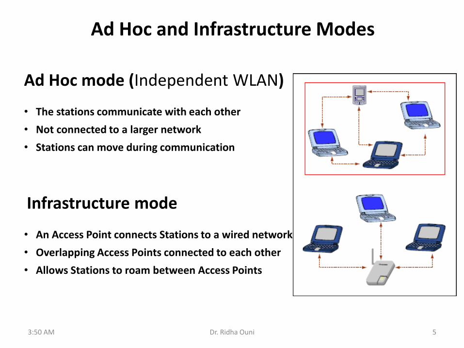
Ad Hoc and Infrastructure Modes
Ad Hoc mode (Independent WLAN) • The stations communicate with each other
• Not connected to a larger network
• Stations can move during communication
Infrastructure mode • An Access Point connects Stations to a wired network
• Overlapping Access Points connected to each other
• Allows Stations to roam between Access Points
3:50 AM Dr. Ridha Ouni 6
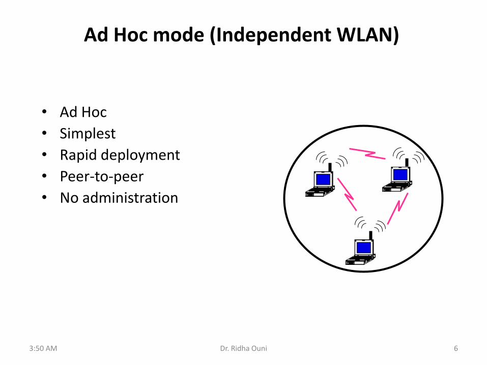
Ad Hoc mode (Independent WLAN)
• Ad Hoc
• Simplest
• Rapid deployment
• Peer-to-peer
• No administration

3:50 AM Dr. Ridha Ouni 7
Ad Hoc mode (Independent WLAN)
Single Cell Multiple Cells

3:50 AM Dr. Ridha Ouni 8
• Can extended range by using an Access Point (acting as a repeater)
Ad Hoc mode (Independent WLAN)
3:50 AM Dr. Ridha Ouni 9
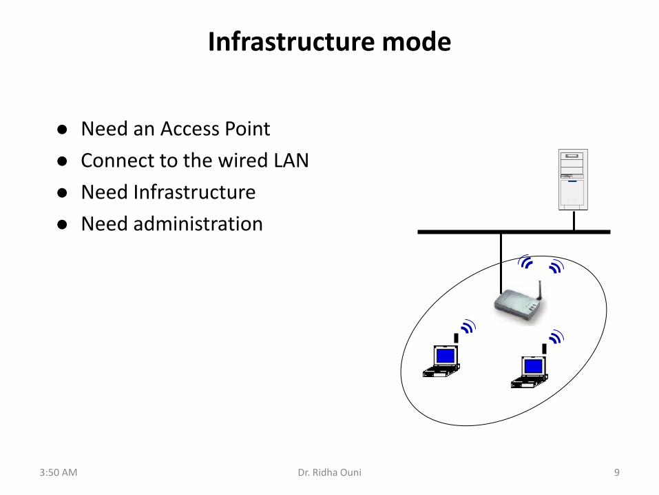
Infrastructure mode
Need an Access Point
Connect to the wired LAN
Need Infrastructure
Need administration

3:50 AM Dr. Ridha Ouni 10
Infrastructure mode
• Many overlapping cells are created,
• Each cell is managed by an AP,
• Interconnected by a distribution system,
• Cover a large area (support many users),

3:50 AM Dr. Ridha Ouni 11
Infrastructure mode
APi APk
Allowing mobility of wireless devices among cells
• An established connection over APi is maintained when the MT becomes near the APj
• Handover (Handoff) • Establish new link over APj, • Release the old link over APi, • Route packets through the new link.
MT
APj
3:50 AM Dr. Ridha Ouni 12
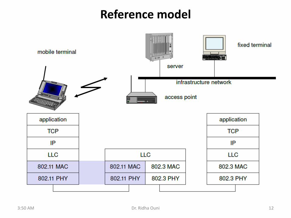
Reference model

7/1/2013 3:50 AM R. Ouni 13
Wireless transmission
• Wireless communication systems consist of: – Transmitters – Antennas: radiates electromagnetic energy into air – Receivers
• RF devices communicate through the transmission and reception of electromagnetic waves
• In some cases, transmitters and receivers are on same device, called transceivers.
Transmitter Receiver
Antenna Antenna

Electromagnetic Waves
Electromagnetic wave: alternates electrical (E) and magnetic (H) fields in a flow characterized by an oscillating waveform
The wave of the electric field and the wave of the magnetic field are propagated perpendicularly to the direction of propagation and to each other.
E. Electrical field (vertical) H. Magnetic field (horizontal)
7/1/2013 3:50 AM 14 R. Ouni

7/1/2013 3:50 AM R. Ouni 15
Antenna
• Transmitter converts electrical energy to electromagnetic waves
• Receiver converts electromagnetic waves to electrical energy
• Same antenna is used for transmission and reception
• Omni-Directional: Power radiated in all directions
• Directional: Most power in the desired direction
• Isotropic antenna: Radiates in all directions equally
• Antenna Gain = Power at particular point/Power with Isotropic Expressed in dBi
Pr = Pt Gt Gr (λ/4πd)2
Omni-directional Directional Isotropic

7/1/2013 3:50 AM R. Ouni 16
• Free-Space loss model Pr/Pt = Gt Gr * [λ /(4πd)]2
where: Pt – transmitted power level Pr – received power level Gr – receive antenna gain Gt – transmit antenna gain λ – carrier frequency wavelength d – distance between transmitter and receiver
• Path loss is defined as L = Pt/Pr – usually measured in dBs (i.e. LdB = 10log10(L) = 10log10(Pt/Pr))
• If Gt and Gr are not given – assume Gt = Gr = 1.
Transmission Characteristic
Defining Range and Coverage
• Range – The maximum distance at which the sender and receiver can mantain a connection
• Coverage – The total area that a wi-fi enabled device can be in and make a connection to an access point
7/1/2013 3:50 AM 17 R. Ouni

18
Signal propagation ranges
distance
Sender (or AP)
transmission
detection
interference
• Transmission range – communication possible
– low error rate
• Detection range – detection of the signal possible
– no communication possible
• Interference range – signal may not be detected
– signal adds to the background noise
7/1/2013 3:50 AM R. Ouni

t
medium busy
DIFS DIFS
next frame
contention window
(randomized back-off
mechanism)
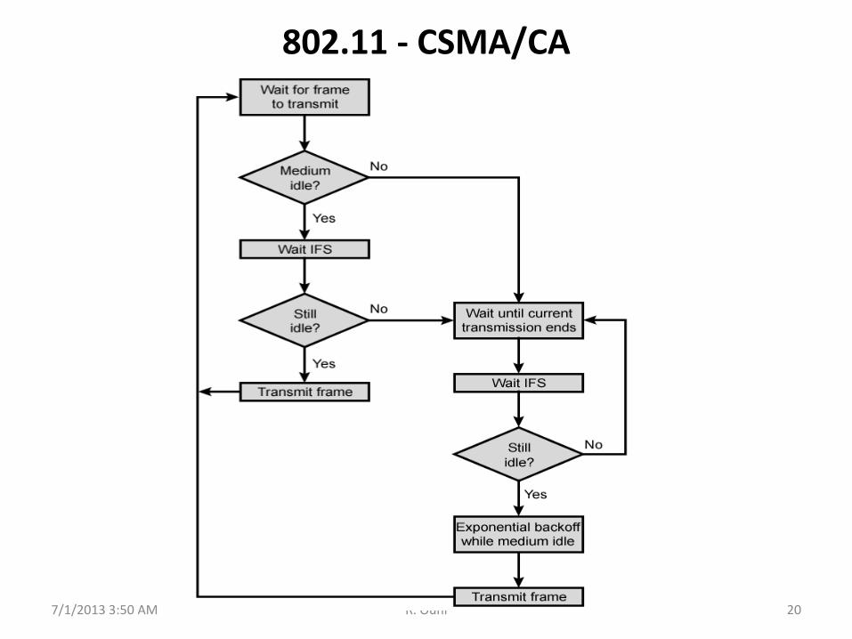
802.11 MAC layer – CSMA/CA
– station which has data to send starts sensing the medium (Carrier Sense based on CCA, Clear Channel Assessment)
– if the medium is free for the duration of an Inter-Frame Space (IFS), the station can start sending (IFS depends on service type)
– if the medium is busy, the station has to wait for a free IFS plus an additional random back-off time (multiple of slot-time)
– if another station occupies the medium during the back-off time of the station, the back-off timer stops (fairness)
slot time
direct access if
medium is free DIFS
7/1/2013 3:50 AM 19 R. Ouni
7/1/2013 3:50 AM R. Ouni 20
802.11 - CSMA/CA
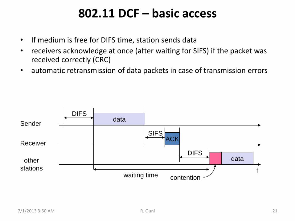
802.11 DCF – basic access
• If medium is free for DIFS time, station sends data
• receivers acknowledge at once (after waiting for SIFS) if the packet was received correctly (CRC)
• automatic retransmission of data packets in case of transmission errors
t
SIFS
DIFS
data
ACK
waiting time
other
stations
Receiver
Sender data
DIFS
contention
7/1/2013 3:50 AM 21 R. Ouni

Computer Networks: Wireless LANs 22
Figure 4-26.(a)The hidden terminal problem. (b) The exposed station problem.
Tanenbaum slide

Computer Networks: Wireless LANs 23
The Hidden Terminal Problem
• Wireless stations have transmission ranges and not all stations are within radio range of each other.
• The trouble is, CSMA is not really a good way to think about wireless because what matters for reception is interference at the receiver, not at the sender.
• Simple CSMA will not work! • C transmits to B. • If A “senses” the channel, it will not hear C’s
transmission and falsely conclude that A can begin a transmission to B.

Computer Networks: Wireless LANs 24
The Exposed Station Problem
• This is the inverse problem.
• B wants to send to C and listens to the channel.
• When B hears A’s transmission, B falsely assumes that it cannot send to C.

Computer Networks: Wireless LANs 25
Wireless LAN Protocols [Tan pp.269-270]
• MACA protocol solved hidden and exposed
terminal problems: – Sender broadcasts a Request-to-Send (RTS) and the intended receiver
sends a Clear-to-Send (CTS).
– Upon receipt of a CTS, the sender begins transmission of the frame.
– RTS, CTS helps determine who else is in range or busy (Collision
Avoidance).

Computer Networks: Wireless LANs 26
Wireless LAN Protocols
Figure 4-12. (a) A sending an RTS to B.
(b) B responding with a CTS to A.
• MACAW added ACKs, Carrier Sense, and BEB
done per stream and not per station.
Tanenbaum slide

Solution to Hidden Terminals
• A first sends a Request-to-Send (RTS) to B
• On receiving RTS, B responds Clear-to-Send (CTS)
• Hidden node C overhears CTS and keeps quiet – Transfer duration is included in both RTS and CTS
• Exposed node overhears a RTS but not the CTS
• D’s transmission cannot interfere at B, As long as it does not interfere with the CTS, it is free to transmit while the data frame is being sent.
A B C
RTS
CTS CTS
DATA
D
RTS
7/1/2013 3:50 AM 27 R. Ouni

802.11 - Reliability
• Use acknowledgements – When B receives DATA from A, B sends an ACK
– If A fails to receive an ACK, A retransmits the DATA
– Both C and D remain quiet until ACK (to prevent collision of ACK)
– Expected duration of transmission+ACK is included in RTS/CTS packets
A B C
RTS
CTS CTS
DATA
D
RTS
ACK
7/1/2013 3:50 AM 28 R. Ouni

802.11 –RTS/CTS
• If medium is free for DIFS, station can send RTS with reservation parameter (reservation determines amount of time the data packet needs the medium)
• acknowledgement via CTS after SIFS by receiver (if ready to receive)
• sender can now send data at once, acknowledgement via ACK
• other stations store medium reservations distributed via RTS and CTS
t
SIFS
DIFS
data
ACK
defer access
other
stations
Receiver
Sender data
DIFS
contention
RTS
CTS SIFS SIFS
NAV (RTS) NAV (CTS)
7/1/2013 3:50 AM 29 R. Ouni

Example - backoff
data
wait
B1 = 5
B2 = 15
B1 = 25
B2 = 20
data
wait
B1 and B2 are backoff intervals
at nodes 1 and 2
B2 = 10
7/1/2013 3:50 AM 30 R. Ouni

802.11 - MAC management
• Synchronization – try to find a LAN, try to stay within a LAN
– timer etc.
• Power management – sleep-mode without missing a message
– periodic sleep, frame buffering, traffic measurements
• Association/Reassociation – The association service is used by mobile stations to connect themselves
to APs.
– Reassociation lets a station change its preferred AP.
– integration into a LAN
– roaming, i.e. change networks by changing access points
– scanning, i.e. active search for a network
• MIB - Management Information Base – managing, read, write
7/1/2013 3:50 AM 31 R. Ouni

802.11 - Frame format
• Types – control frames, management frames, data frames
• Sequence numbers – important against duplicated frames due to lost ACKs
• Addresses – receiver, transmitter (physical), BSS identifier, sender (logical)
• Miscellaneous – sending time, checksum, frame control, data
Frame
Control
Duration
ID
Address
1
Address
2
Address
3
Sequence
Control
Address
4 Data CRC
2 2 6 6 6 6 2 4 0-2312 bytes
version, type, fragmentation, security, ...
7/1/2013 3:50 AM 32 R. Ouni

frame
control duration
address
1
address
2
address
4
address
3 payload CRC
2 2 6 6 6 2 6 0 – 2312 4
seq
control
802.11 frame: addressing
Address 2: MAC address of wireless host or AP transmitting this frame
Address 1: MAC address of wireless host or AP to receive this frame
Address 3: MAC address of router interface to which AP is attached
Address 3: used only in ad hoc mode
7/1/2013 3:50 AM 33 R. Ouni

Internet router
AP
H1 R1
AP MAC addr H1 MAC addr R1 MAC addr
address 1 address 2 address 3
802.11 frame
R1 MAC addr AP MAC addr
dest. address source address
802.3 frame
802.11 frame: addressing
7/1/2013 3:50 AM 34 R. Ouni

frame
control duration
address
1
address
2
address
3 payload CRC
2 2 6 6 6 2 6 0 - 2312 4
seq
control
address
4
Type From
AP Subtype
To
AP
More
frag WEP
More
data
Power
mgt Retry Rsvd
Protocol
version
2 2 4 1 1 1 1 1 1 1 1
802.11 frame: more
duration of reserved transmission time (RTS/CTS)
frame seq # (for reliable ARQ)
frame type (RTS, CTS, ACK, data)
7/1/2013 3:50 AM 35 R. Ouni