wireless network intrusion detection system
TRANSCRIPT

Wireless Network Intrusion Detection System
Project Description and Analysis Report
Author: Calvin Jia Liang, Student, CPE
Advisor: Clinton Staley, Professor, CSC
Department of Computer Engineering
College of Engineering
California Polytechnic State University
May 28th, 2014

Overview
The Wireless Network Intrusion Detection System is a network-based intrusion detection system
(IDS) that listens on a wireless network. The IDS device is a self-contained single-board-
computer capable of monitoring the user’s wireless network, detecting suspicious network
traffic, and reporting to the user via email. The device has two network interfaces: the wireless
interface is used to monitor network traffic, and the wired interface is used to configure the
system and to send out detection alerts. The system requires minimal setup, configuration, and
maintenance. It is a relatively inexpensive device that tries to improve user’s situational-
awareness of one’s wireless network.
Problem Statement
Traditional security solutions for home users are mostly host-based detection, which consumes
host resources. This problem is more apparent in resource-limited environments such as
smartphones and tablets. In addition, once a machine is infected, the malware can disable, or
hide from, any host-based security system, giving the user a false sense of security. Therefore,
host-based security solution alone is not sufficient to solve today’s security problem. One of the
solutions is to broaden the detection scope by introducing a network-based detection system.
However, most of the network-based security appliance available in the market today focus on
enterprise environments. As a result, those appliances are generally too expensive to purchase,
too difficult to setup, and too complex to maintain. This project is an attempt to build an
affordable network-based detection system suitable for home environments.
Objective
The objective of the project is to design and implement a basic network-based intrusion detection
system usable by a non-technical user. Since the target consumer is non-technical, the setup
process should be as simple as possible. As a result, the system should require as little
modification as possible to the user’s network configuration. In addition, once the system is
running, it should be able to carry out its task without the need of further user involvement.
Furthermore, the reports and alerts generated by the system should be digestible by non-technical
user. Lastly, it should support a majority of household network configurations. The system may
assume that the network configuration and setting of the user does not change while the system is
running.

Components and Costs
The hardware components and costs for this project is listed in Table 1. The software
components and costs for this project is listed in Table 2.
Component Cost (USD)
ODROID-U3 Single-Board-Computer $80
TP-LINK TL-WN722N USB Network Adapter $35
5V 2A 2.5x0.8mm AC to DC Power Adapter $5
16GB Micro SD Card $10
$130
Table 1: List of Hardware Components and Costs
Component Cost (USD)
Xubuntu 13.10 $0
aircrack-ng suits $0
mysql suits $0
apache2 $0
python and python cgi $0
barnyard2 $0
snort $0
libtins and dot11decrypt $0
ruby and snorby $0
sendmail $0
$0
Table 2: List of Software Components and Costs

System Design
The current system employs an out-of-band wireless sniffer with local processing capability.
Figure 1 illustrates a possible network configuration with the IDS. There are a few design
decisions that need to be addressed for a network-based detection system. The discussions are
outlined in the following sections to explain the reasons behind the current system design.
Figure 1: Network Configuration Diagram of a Household Network with an All-in-One Modem and IDS.
Setup: In-Line vs. Out-of-Band
The first question is the position of the detection system in a network configuration. An in-line
setup means that the detection device is an essential component of the network path; all network
traffic must pass through the device before routing to its destination. An out-of-band setup means
that the detection device is an additional end-host of the network; the network traffic is sniffed
by the device but the network path is not altered. An in-line setup enables the detection device to
decrypt otherwise encrypted traffic and to prevent attacks in real-time (becomes an Intrusion
Prevention System). However, an in-line setup is generally more difficult because of the
insertion of an additional device to the network path. In addition, such device usually require
better hardware as it needs to both process and forward all network packets. On the other hand,
an out-of-band setup cannot decrypt some network traffic nor to prevent an attack; however, it is
easier to setup and less complex to build. Since the device is for general home user, the ease of
use and simplicity justify for the lack of features that the device may offer. Therefore, the design
employs an out-of-band setup.

Sniffing: Wire vs. Wireless
The next question is the method to obtain network packets. Since the setup is out-of-band,
obtaining network packets become a crucial problem. A modern network consists of four
components: modem, router, switch, and wireless access point. Some households have an all-in-
one configuration where all four components are compressed into one device. Some have a split
configuration where a network station, which acts as a router, switch, and wireless access point,
is connected to a modem. Other less popular configurations, such as a wireless access point
directly connected to a modem or a wire-only network station directly connected to a modem, are
also possible. With these configurations in mind, a wire sniffer needs to either place itself
between the network station and the modem through a splitter, or connects itself to a monitoring
port in the network station. Since setting up a monitoring port requires substantial technical
knowledge, the only user-friendly way to setup a wire sniffer is through a hardware splitter.
However, a user with all-in-one configuration will not be able to set up a wire sniffer because all
connections are wired internally within one device. On the other hand, a wireless sniffer suffers
from radio interference, has decryption overhead, and is unable to obtain wired network traffic;
nevertheless, it is suitable to most household network configurations. Although a wire sniffer is
more efficient and reliable, a wireless sniffer is more deployable. Therefore, the device uses a
wireless sniffing technique.
Processing: Remote vs. Local
The last question is the location to process and store the detection data. A remote method
requires sending the suspicious packets to a cloud server for additional processing, storage, and
reporting. A local method process, store, and report all suspicious activities within the local
device. The remote method can offload some amount of workload and storage from the device,
making it less expensive to produce. The remote method can also centralize the data acquisition,
processing, and reporting mechanism, which enable intelligence sharing and more powerful
analysis technique. However, sending user network traffic over the Internet and storing those
information in a cloud server raise privacy concerns. Therefore, a secure host-server
communication protocol and packet sensitization techniques become a crucial challenge for
remote processing. In order to simplify the technical challenge of this project, the device uses a
local processing method with the architectural capability of sending the data to a remote server.

System Architecture
The system consists of a series of components in which the output of one is the input of another.
Figure 2 shows the architecture and basic data flow of the system.
Figure 2: System Architecture and Basic Data Flow
Sniffing Driver
In order to obtain all traffic in a wireless network, the system must put the wireless adapter into
monitor mode. Airmon-ng is used to create a new network interface mon0, which returns all
network packets seen by the wireless adapter regardless of its destination. Since not all wireless
adapters can be put into monitor mode, the system uses a compatible TP-LINK TL-WN722N
USB Network Adapter.
Decryption Driver
A large majority of household wireless networks use either Wired-Equivalent-Privacy (WEP) or
WiFi-Protected-Access (WPA) as their wireless protection mechanism. Therefore, a decryption
driver is required to decrypt the protected packets. The system uses dot11decrypt as the
decryption driver. Dot11decrypt will create a new network interface tap0, which transforms
encrypted 802.11 packets from the sniffing driver to plaintext ethernet packet.

Detection Engine
The signature detection engine is the heart of an IDS because it is used to process all packets and
to detect suspicious activity based on the pre-defined rules. The engine scans each plaintext
ethernet packet from the decryption driver and raises an alert if a packet, or series of packets,
matches a signature. The full packet content is saved in a file for future analysis. The system uses
Snort as its detection engine.
Database
Since data residing in a file is difficult to perform analysis, the system must parse the logs
generated by the detection engine to a database. This task is carried out by Barnyard2, mysql-
client, and mysql-server. Barnyard2 can parse the snort generated logs to mysql-client. Then,
mysql-client will forward the data to a mysql-server database for permanent storage. Since
mysql-client is able to forward the data both remotely and locally, the system is capable of
forwarding alert data to a remote server if necessary. The current design is for the mysql-client to
forward data to a local mysql-server.
Notification Engine
The notification engine is used to inform the user if there are substantial amount of alerts
reported by the detection engine. The engine queries the database in a constant interval. If the
number of alerts within the interval exceeded a threshold, an alert email will be sent to the user
mailbox. The system uses sendmail to send out emails through SMTP. The current design will
send an email if there are more than 50 SMTP or ICMP packets within 24 hours. In addition,
since the email is sent through a wired interface, it will not trigger an alert in the wireless
detection.
Web Interface
A web-based control and configuration panel is needed to setup and monitor the system. A
HTTPS web server is used to accomplish this task using apache2 with SSL. A password is
required prior to system access in order to prevent unauthorized tampering. Once a user is
granted access to the device, the web server will display contents generated by the python cgi
script. Lastly, an advanced control panel is available via Snorby, a ruby-based IDS management
tool.

System Behavior
The system has three operational states: startup, configuration, and monitoring. The startup and
configuration states are mainly for initialization of different modules. After the modules are
successfully initialized, the system will stay in the monitoring state indefinitely to carry out its
function as an IDS. Figure 3 illustrates the modules that made up the system.
Figure 3: System Services and Modules
Startup
The linux kernel boots up, which starts all system services. Those services include network-
manager, apache2 web server, network drivers, mysql database server, and SMTP mail server.
The network-manager is configured to send a DHCP host-name request to the default gateway in
order to setup a reliable host-name for the system. In addition, a custom startup script is also
executed to remove all residue data left in the previous run. The script deletes all user
configuration files, snort alerts and logs, and all tables in the database. Then, the database is
rebuilt using a ruby script provided by Snorby. Upon the completion of the script, the system
enters configuration state.

Configuration
The system waits for user HTTPS connection during configuration state. Once the user
successfully establishes a HTTPS connection, the system generates web pages through the
python cgi script. (Note that the script cannot execute any privileged command because it is run
as a regular user. A workaround is for the script to execute a C program that has the necessary
privilege.) In the first setup step, the script asks the user to choose a target essid from a list of
essid. A list of available essid is obtained by executing a custom C program that scans all
available wireless networks in the area. In the second setup step, the script gets the essid,
displays key information of the network associated with the chosen essid, writes those
information to a file, and prompts the user for password. The network information is obtained by
executing a custom C program that filters the beacon information using the supplied essid. In the
third setup step, the script gets the password, checks the validity of the password, and initializes
all other modules. The system checks the password by connecting to the target wireless network.
If the connection is established, the password is deemed valid. If the connection failed, the
system will prompt the user to go back to step one. Again, the password validation and module
initialization are performed by a C program. Since all modules act as daemon processes, the C
program starts each module without waiting for it to exit. The modules started by the C program
are airmon-ng, dot11decrypt, snort, barnyard2, snorby, and mail. After the C program completes
without error, the script enters the last setup step. The script prompts for the user information,
and writes the information to a file. The mail module will detect creation of a user information
file and send an email notification to the user for setup completion.
Monitoring
The system automatically process network packets and alert user in the monitoring state. The
airmon-ng interface puts the wireless driver into monitor mode in order to capture all wireless
traffic associated with the specified access point. The dot11decrypt interface listens on the
airmon-ng interface and outputs plaintext ethernet packets. Snort listens on the dot11decrypt
interface and produces alert logs. Barnyard2 parses the snort logs to mysql-server using the
mysql-client module. The mail module queries the mysql-server periodically to detect abnormal
activities and alerts user if certain activities exceeded the threshold. The snorby module queries
the mysql-server upon user request and displays the data to the web interface.

Limitation
Known Issues
The network-manager nmcli module is unable to send DHCP host-name request from command
line. A workaround is to add the request directly in the network-manager interface save file.
libtins contains a bug where the third packet of a WPA/WPA2 handshake can never be
processed. A workaround is to modify the handshake-capturer.cpp file in the source code and
recompile the library.
dot11decrypt contains a bug where the WEP input from command line is expected in raw byte
format. A workaround is to modify the main.cpp file in the source code and recompile the
program.
Barnyard2 2.1.13 raises an exception when trying to access signature information in the
database. A workaround is to downgrade barnyard2 to 2.1.9.
Unresolved Issues
The system does not work on an open wireless network because snort is unable to process raw
802.11 packets.
The system may miss packets due to radio interference or process delay.
The system may perform poorly in a 802.11n or newer wireless network due to increased
transmission speed of the protocol.
If the system is not positioned close to the access point, some devices may be missed.
Some kernel modules do not function properly after a kernel update.
If the DHCP server of the user’s gateway does not accept domain-name request, it will be
extremely inconvenient for the user to access the web interface of the system.

Future Works
Support open wireless network sniffing so that the system can be used under an open network.
Remote processing and reporting system so that data analytics, data storage, and alert reports are
centralized in a cloud server.
Automatic system updates so that system modules, firmwares, and detection rules can be up-to-
date.
Improved data analytics to form a more accurate and substantial report.
Additional configuration options such as password setting, rule exclusion, and report formats.
Wireless-only configuration to eliminate the need of a wired connection to the network station.
Final Remarks
The system is a proof-of-concept that building a home-use IDS is feasible. The unit cost is within
an affordable amount. (See Table 1 and Table 2.) The setup process is relative simple; it does not
require modification of a working network. (See Appendix I.) Most of the technical challenges
can be overcome by specialized software and hardware. There are large amount of open-source
security modules available in the web. The challenge is to combine those modules together to
form a complete system. The majority of obstacles occurred during the project are due to
installation dependencies, configuration problems, integration issues, and third-party program
deficiencies. Finally, there are a few comments about designing a network-based security
appliance for home environment. First, although a cloud-sourcing design is more beneficial to its
fully self-contained counterpart, careful design must be made in order to ensure the privacy of
the user and the security of the system; otherwise, the system may turn against the user by
leaking undesirable information from the user’s network. Secondly, wire sniffing may be more
reliable than wireless sniffing; however, unless a monitoring port is readily available in every all-
in-one modem, or that users stop using such modem altogether, wire sniffing will remain
unusable by a large population of network users.
Additional Materials
User Manual - Appendix I
Application Installation and Configuration Notes - Appendix II
Xubuntu Directory Paths - Appendix III

Appendix I - User Manual
Hardware Setup
1. Connect the USB Wireless Adapter to a USB port on the device. Try to put the Wireless
Adapter as close as possible to your Wireless Access Point.
2. Connect the device to your Home Router through an Ethernet Cable.

3. Connect the power adapter to the device.
4. A blinking blue light indicates that the device is running. Wait for about two minutes to
let the system boot up. Then, go to System Setup for configuring the system.

System Setup
1. Open up a browser in a machine connected to the home network.
2. In the address bar of the browser, type https://wlids, and hit enter.
3. A warning page message about the site’s certificate will appear. Ignore the warning and
proceed to the site.
If the browser cannot load the page, it is either:
a. The machine that you are using is not connected to the same network as the IDS.
Try to use a computer that has a wire connection to the router.
b. The DHCP service in your router is not functioning properly. Try to find the IP
address of the IDS by logging in to your router and accessing the DHCP client
table.
4. An authentication prompt will appear. Use the following information to log in:
User Name: admin
Password: wireless

5. Select the name of your network in the drop-down menu. Then click proceed.
If you do not find your network in the drop-down menu, try again by refreshing the page.
6. Verify that the information about your wireless network is correct. Type the password or
key of your wireless network to the input box. Then click proceed.

7. The system will check your password by connecting to your wireless network. Once the
password is verified, a confirmation page will be loaded. Click proceed to continue.
If you have typed in the wrong password, simply click the reset button to try again.
8. Type your email address in the input box. (You may want to leave the other setting as
is.) Click submit to store your configuration.
9. Congratulations, the setup process is completed. See After the Setup for features of the
system.
After the Setup
● An notification email titled “IDS Setup Complete” will be sent to your email shortly
after you submitted your information. It is very likely that the email will end up in your
Junk folder.
○ Some email provider may treat our email as SPAM so it will never show up in
your mailbox.
○ You may change any component of the notification configuration anytime after
the setup. If you do, a new notification email will be sent.
● An alert email will be sent, abiding by the notification interval, if the system detects
abnormality in your wireless network. (Currently, an alert is triggered if there is more
than 50 SMTP or ICMP packets within 24 hours.)
● An email will be sent, abiding by the notification interval, regardless of detection result if
you choose “No” in the “Send notification ONLY IF abnormality is detected”.
● You may return to the Notification Configuration page anytime by typing https://wlids
in your browser.
● Other than email notification, a control-panel is available by clicking the link in the
Notification Configuration page. You can log in to the system using the following
information.
Email: [email protected]
Password: snorby
● You may turn off the system by pressing the power button located at the top of the
device. All data will be erased once the device is turned off.

Appendix II - Application Installation and Configuration Notes
libtins:
● {libtins-master-directory}/src/handshake-capturer.cpp
○ change the capture condition for do_insert(eapol, 1) to if (!eapol->secure())
● ./configure --enable-c++11 --enable-dependency-tracking
dot11decrypt:
● {dot11decrypt-master-directory}/main.cpp
○ change the string hex to actual hex by convert std::string to regular C char[], using
strtol() in a loop, and convert it back to std::string.
Apache2 Web Server:
● install apache2 and apache2-utils
● enable ssl by “a2enmod ssl”
● make a ssl-site.conf in the /etc/apache2/sites-available directory
● enable website configuration file by “a2ensite ssl-site”
● enable cgi module by “a2enmod cgi”
● to enable login, use htpasswd to create user account and password
○ htpasswd -c -b pwd [usrname] [password]
● save this file under /etc/apache2/auth/
● replace the following block in the /etc/apache2/apache2.conf
<Directory /var/www/>
Options Indexes FollowSymLinks ExecCGI
AllowOverride None
AddHandler cgi-script .cgi
SSLRequireSSL
AuthType Basic
AuthName "Restricted Security Server"
AuthUserFile /etc/apache2/auth/pwd
Require valid-user
</Directory>
● set the name of the web server to the name of the localhost
ServerName localhost
● set the user of apache2 as current user by modifying /etc/apache2/envvar
● save all web pages in /var/www/ folder
● chmod 755 all cgi files

MySQL Server and Client:
● install mysql-client and mysql-server
● create user snorby
○ CREATE USER ‘snorby’@'localhost' IDENTIFIED BY ‘wireless’;
● grant user access right
○ mysql -u root -p
○ mysql> create database snort;
○ mysql> grant ALL on *.* to snorby@localhost;
Barnyard2:
● ./configure --enable-dependency-tracking --with-mysql --with-mysql-libraries={mysql-
library-path} --enable-mysql-ssl-support
● cp {barnyard2-master-directory}/etc/barnyard2.conf /etc/snort/
● uncomment and appropriately modify the following lines
○ config daemon
○ config hostname
○ config interface
○ output database
○ config logdir
○ config waldo_file
Snorby:
● Download all prerequisites
○ apt-get install gcc g++ build-essential libssl-dev libreadline5-dev zlib1g-dev
linux-headers-generic libsqlite3-dev libxslt-dev libxml2-dev libyaml-0-2 libyaml-
dev libtcltk-ruby
○ apt-get install imagemagick git-core libmagickwand-dev
○ apt-get install wkhtmltopdf ruby-dev
○ gem install tzinfo builder memcache-client rack rack-test erubis mail text-format
bundler thor i18n sqlite3-ruby
○ gem install rack-mount
○ gem install rails
○ gem update
● install snorby
○ bundle install
● setup snorby
○ modify username and password in {snorby-path}/config/database.yml
○ modify {snorby-path}/config/snorby_config.yml
○ bundle exec rake snorby:setup

Snort:
● snort.conf
○ output unified2: filename snort.u2, limit 128
Scripts:
● make a directory in /etc/info
● create a file hw.info with sniff_iface in the first line and serv_iface in the second line
● compile all .c files with the corresponding names
● copy all binary to /bin/
● chmod ug+s for all script binaries in /bin/
Misc:
● add restart_system script to /etc/init.d/
○ add sym-link to /etc/rc[1-5].d/
● add the following line under ipv4 section in /etc/NetworkManager/system-connections
○ dhcp-send-hostname=wlids
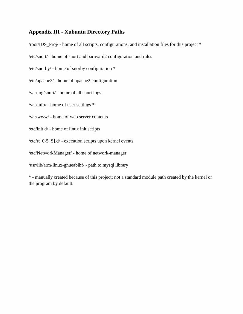
Appendix III - Xubuntu Directory Paths
/root/IDS_Proj/ - home of all scripts, configurations, and installation files for this project *
/etc/snort/ - home of snort and barnyard2 configuration and rules
/etc/snorby/ - home of snorby configuration *
/etc/apache2/ - home of apache2 configuration
/var/log/snort/ - home of all snort logs
/var/info/ - home of user settings *
/var/www/ - home of web server contents
/etc/init.d/ - home of linux init scripts
/etc/rc[0-5, S].d/ - execution scripts upon kernel events
/etc/NetworkManager/ - home of network-manager
/usr/lib/arm-linux-gnueabihf/ - path to mysql library
* - manually created because of this project; not a standard module path created by the kernel or
the program by default.