wireless powered communications with finite battery and
TRANSCRIPT
arX
iv:1
705.
0907
6v2
[cs
.IT
] 2
0 D
ec 2
017
1
Wireless Powered Communications with Finite
Battery and Finite Blocklength
Onel L. Alcaraz Lopez, Evelio Martın Garcıa Fernandez, Richard Demo Souza
and Hirley Alves
Abstract
We analyze a wireless communication system with finite block length and finite battery energy,
under quasi-static Nakagami-m fading. Wireless energy transfer is carried out in the downlink while
information transfer occurs in the uplink. Transmission strategies for scenarios with/without energy
accumulation between transmission rounds are characterized in terms of error probability and energy
consumption. A power control protocol for the energy accumulation scenario is proposed and results
show the enormous impact on improving the system performance, in terms of error probability and
energy consumption. The numerical results corroborate the existence and uniqueness of an optimum
target error probability, while showing that a relatively small battery could be a limiting factor for some
setups, specially when using the energy accumulation strategy.
Index Terms
Finite blocklength communications, wireless energy transfer, finite battery, power control.
I. INTRODUCTION
The Internet of Things (IoT) is a recent communication paradigm which promises to bring
wireless connectivity to “...anything that may benefit from being connected...” [1], ranging from
tiny static sensors to vehicles and drones. Consequently, coming wireless communication systems
O. Lopez and H. Alves are with the Centre for Wireless Communications (CWC), University of Oulu, Finland.
Onel.AlcarazLopez, [email protected].
E.M.G. Fernandez is with Federal University of Parana (UFPR), Curitiba, Brazil. [email protected].
R.D. Souza is with Federal University of Santa Catarina (UFSC), Florianopolis, Brazil. [email protected].
This work was supported by CNPq, CAPES, Fundacao Araucaria (Brazil) and Academy of Finland (grant no 303532), and
the Program for Graduate Students from Cooperation Agreements (PEC-PG, of CAPES/CNPq Brazil).
2
will have to support a much larger number of connected devices, including autonomous machines
and devices, with applications having stringent requirements on latency and reliability as [2]:
factory automation, with maximum latency around 0.25-10ms and maximum error probability
of 10−9; smart grids (3-20ms, 10−6), professional audio (2ms, 10−6), etc. Powering and uninter-
rupted operation of such potential massive number of IoT nodes is a major challenge. [3]. Energy
harvesting (EH) techniques have recently drawn significant attention as a potential solution, and
authors in [4] provide an insightful formula regardless of the type of energy source for the
approximate capacity of the EH channel over Additive White Gaussian Noise (AWGN) for
large and small battery regimes. Wireless Energy Transfer (WET) is a particularly attractive EH
technique because radio-frequency (RF) signals can carry both energy and information, which
enables energy constrained nodes to harvest energy and receive information [5], [6], allowing to
prolong their lifetime almost indefinitely.
The exploitation of WET becomes very attractive specially for IoT scenarios where replacing
or recharging batteries require high cost and/or can be inconvenient or hazardous (e.g., in toxic
environments), or highly undesirable (e.g., for sensors embedded in building structures or inside
the human body) [7]. With further advances in antenna technology and EH circuit designs, WET
is believed to become very efficient such that it will be implemented widely in the near future.
Indeed, WET techniques are now evolving from theoretical concepts into practical devices for
low-power electronic applications [8]. Wireless-powered communication networks (WPCNs),
where the wireless terminals are powered only by WET and transmit their information using
the harvested energy, have been widely investigated in the last years. The feasibility of WET
for low-power cellular applications has been studied using experimental results, which have
been summarized in [9]. A classic multi-user WPCN was investigated in [10], where authors
develop a “harvest-then-transmit” protocol which allows users to first collect energy from the
signals broadcasted by a single-antenna hybrid access-point (AP) in the downlink and then to
use their harvested energy to send independent information to the hybrid AP in the uplink.
Diverse strategies have been considered in the recent scientific literature in order to improve
the performance of WPCNs, such as relay-assisted [11]–[23], Hybrid Automatic Repeat-reQuest
(HARQ) [24], and power control [21]–[23], [25]–[27], mechanisms. Works in [21]–[23] are
particularly interesting since they propose energy accumulation strategies so that a wireless-
powered relay can efficiently assist a communication link. Specifically, an accumulate-then-
forward protocol for a multi-antenna relay is presented in [21] while the charging/discharging

3
behaviors of the relay battery are modeled as a finite-state Markov chain. The relay battery is
modeled similarly in [22], and the authors develop a power splitting-based energy accumulation
scheme. Therein, a predefined energy threshold is set so the relay can determine whether it has
sufficient energy to perform jointly energy accumulation and information forwarding. Otherwise,
all the received signal power will be accumulated at the relay. Finally, a cooperative dilemma
at the relay, concerning on whether to transfer its harvested energy to the source or to act as
an information relay to the destination, is investigated in [23]. Authors resolve this dilemma by
providing insights into the optimal positioning suited for either energy relaying or information
transfer.
All the above studies are under ideal assumption of communicating with large enough blocks in
order to invoke Shannon theoretic arguments to address error performance. However, as pointed
out in [28], important characteristics of WET systems are: i) power consumption of the nodes
on the order of µW; ii) strict requirements on the reliability of the energy supply and of the data
transfer; iii) information is conveyed in short packets. This third requirement is due to intrinsically
small data payloads, low-latency requirements, and/or lack of energy resources to support longer
transmissions [29]. This agrees well with several aforementioned IoT scenarios with stringent
latency requirements. Although performance metrics like Shannon capacity, and its extension
to nonergodic channels, have been proven useful to design current wireless systems, they are
not necessarily appropriate in a short-packet scenario [30], where a more suitable metric is the
maximum achievable rate at a given block length and error probability. This metric has been
characterized in [31], [32] for both AWGN and fading channels. Indeed, recent works in finite-
blocklength information theory have shed light on a number of cases where asymptotic results
yield inaccurate engineering insights on the design of communication systems once a constraint
on the codeword length is imposed, e.g., in fast fading scenarios and low-rate transmissions [33]–
[37]. Recently, WPCNs under finite blocklength regime have received attention in the scientific
community. In [38] we analyze and optimize a single-hop wireless system with energy transfer
in the downlink and information transfer in the uplink, under quasi-static Nakagami-m fading
in ultra-reliable communication (URC) scenarios, representative of wireless systems with strict
error and latency requirements. The results demonstrate that there is an optimum number of
channel uses for both energy and information transfer for a given message length. The impact
of a decode-and-forward relay-assisted communication setup is evaluated in [39] in terms of
throughput and delay, also in URC scenario. Achievable channel coding rate and mean delay

4
of a point-to-point EH system with finite blocklength are investigated in [40] for an AWGN
channel. On the other hand, subblock energy-constrained codes are investigated in [41], and a
sufficient condition on the subblock length to avoid energy outage at the receiver is provided. In
[29], a node charged by a power beacon attempts to communicate with a receiver over a noisy
channel. Authors investigate the impact of the number of channel uses for WET and for wireless
information transfer (WIT) on the system performance. Also, tight approximations for the outage
probability/throughput are given in [42] for an amplify-and-forward relaying scenario, while
retransmission protocols, in both energy and information transmission phases, are implemented
in [28] to reduce the outage probability compared to open-loop communication.
Moreover, power allocation strategies have been recently investigated to enhance the perfor-
mance of short packets communication systems. In [43], the authors investigate the optimal
power allocation algorithms for low-density parity-check (LDPC) codes with specific degree
distributions using multi-edge-type density evolution error boundaries, while the error probability
in delay-limited block-fading channels is analyzed. A single point-to-point wireless link operating
under queuing constraints, in the form of limitations on the buffer violation probabilities, is con-
sidered in [44]. The performance of different transmission strategies (e.g., variable-rate, variable-
power, and fixed-rate transmissions) is also studied at finite blocklength regime. Furthermore,
the maximum achievable channel coding rate at a given blocklength and error probability, when
the codewords are subject to a long-term (e.g., averaged-over-all-codeword) power constraint
is investigated in [45], in which power control strategies for both AWGN and fading channels
are developed. However, to the best of our knowledge, there are only few papers, e.g., [25]–
[27], where power allocation strategies are proposed for WPCNs but based on the assumption
of infinite blocklength. Particularly interesting is the work in [27], where authors propose a
low-complexity solution, called fixed threshold transmission (FTT) scheme, and show that its
performance is very close to the optimal. This strategy assumes a transmit power threshold to
determine whether transmission takes place or not. If the channel state of the current transmission
attempt is of poor quality, then saving energy for future transmission attempts may be a wiser
choice.
This paper aims at WPCN scenarios with short packets, but with several differences with
respect to the related literature. The system is composed of a point-to-point communication link
under Nakagami-m quasi-static fading, with WET in the downlink and WIT in the uplink, as
in many of the related works. However, we analyze the error probability and average energy

5
consumption under a finite battery constraint for scenarios with and without energy accumulation
between transmission rounds while taking into account the sensitivity of the energy harvester,
which is a parameter of practical interest. In addition, we propose a power control protocol
for the scenario with energy accumulation between transmission rounds in order to enhance
the system performance in terms of error probability by taking advantage of the channel state
information (CSI) at the transmitter side, while at the same time the average energy consumption
improves. The proposed strategy could be seen as a variant of the finite-blocklength scenarios
of the FTT scheme investigated in [27]. Notice that the infinite blocklength assumption in [27]
leads to a non-optimal transmit power threshold in our scenario, as the true required threshold
is much higher when communicating with short packets.
The main contributions of this work can be listed as follows:
• Accurate closed-form approximations for the error probability in scenarios where all the
energy harvested at each WET phase is used to transmit in the next WIT phase. Here,
channels for WET and WIT phases are assumed reciprocal, which is different from the result
in [38] where those channels are independent and only infinite battery setup is considered;
• A power control algorithm for scenarios with energy accumulation between transmission
rounds. Proposed algorithm takes into account the message blocklength and consequently
it can be seen as a more practical implementation of the FTT scheme proposed in [27].
Notice that allowing energy accumulation between transmission rounds is beyond the scope
of our previous work in [38];
• An analytical approach is provided that shows how misleading any scheme based on the
assumption of infinite blocklength compared to finite blocklength is, which validates our
assumptions and modeling;
• An analysis of the average energy consumption in addition to the error probability, which
is not addressed in [27] nor [38], for scenarios with and without energy accumulation
between transmission rounds. Saving energy for future transmissions allows to improve the
system performance in terms of error probability while reducing the energy consumption.
A relatively small battery could be a limiting factor for some setups, and specially when
using the energy accumulation strategy which also depends heavily on the chosen target
error probability.
Next, Section II presents the system model and assumptions. Section III discusses a scenario

6
without energy accumulation between transmission rounds, while the case with energy accumu-
lation is analyzed in Section IV by proposing a power control protocol. Section V presents the
numerical results. Finally, Section VI concludes the paper.
Notation: X ∼ Γ(m, 1/m) is a normalized gamma distributed random variable with shape factor
m, Probability Density Function (PDF) fX(x) = mm
Γ(m)xm−1e−mx and Cumulative Distribution
Function (CDF) FX(x) = 1 − Γ(m,mx)Γ(m)
. Let E[ · ] denote expectation, | · | is the absolute value
operator, and 1(·) is an indicator function which is equal to 1 if its argument is true and 0
otherwise. Also, P[A] is the probability of event A, while min(x, y) and max(x, y) are the
minimum and maximum values between x and y, respectively.
II. SYSTEM MODEL AND ASSUMPTIONS
Consider the point-to-point wireless communication system shown in Fig. 1, in which S
represents the information source, D is the destination, and both are single antenna, half-duplex,
devices. D is assumed to be externally powered, while S may be seen as a sensor node with very
limited energy supply and finite battery. First, D charges S during v channel uses in the WET
phase, and doing that, acts as an interrogator, requesting information from S. Then, S transmits
k information bits over n channel uses in the WIT phase. We define a “transmission round”
as a pair of consecutive WET and WIT phases, in that order. Notice that S can transmit its
data using all the energy available in its battery at the start of each WIT phase (without energy
accumulation between transmission rounds) or just make use of a part of that energy, saving
the rest for future transmissions (with energy accumulation between transmission rounds). We
consider a time-constrained setup, which implies that D has to decode the received signal for
each arriving information block.
In addition, channel reciprocity holds as shown in Fig. 1, because we consider the same
frequency bands for both WET and WIT phases1. We assume low-mobility scenarios, for which
the coherence time is large enough such that channels are quasi-static, e.g., the fading process
is constant over a transmission round (v + n channel uses) and independent and identically
1The reciprocity principle is based on the property that electromagnetic waves traveling in both directions will undergo the
same physical perturbations. Therefore, if the link operates on the same frequency band in both directions, the impulse response
of the channel observed between any two antennas should be the same regardless of the direction [46]. This is a very common
assumption in many works related with WPCNs, e.g., [24], [47]–[49]. In practice, the non-symmetric characteristics of the RF
electronic circuitry would affect the reciprocity property, and some calibration methods would be required [46].

7
S Dh
h
WET
WIT
v ‐ channel uses
n - channel uses
Fig. 1. System model with WET in the downlink and WIT in the uplink.
distributed from round to round. To support this assumption, let Th be the coherence time, thus
Th ≈ 1fm
= cfvd
, where fm = vdcf is the maximum Doppler spread, vd is the device velocity, c is
the speed of light and f is the transmission frequency. Fig. 2a shows the approximate coherence
time as a function of the device velocities for several transmission frequencies. For velocities
below 20km/h and for all the frequencies being considered, the coherence time is expected to
be above 10ms. Also, if we fixed the transmission frequency to 2GHz while selecting low-
mobility scenarios, we can see in Fig. 2b the coherence time in channel uses as a function of the
channel use duration. For low velocities (vd ≤ 3km/h), the coherence time is always above 1000
channel uses. Therefore, for low mobility scenarios and finite (short) blocklength, the quasi-static
assumption holds, as well as the reciprocity of the channels, since it is expected that v+n ≤ Th
Tc.
The fading is modeled using the Nakagami-m distribution, which is a generalized distribu-
tion that can model different fading environments by adjusting its parameters to fit a variety
of empirical measurements. In fact, multipath fading can be adequately characterized by the
Nakagami-m distribution, and it can model also the Rayleigh and Rician distributions, as well
as more general ones [50]. We consider normalized channel gains, then g = |h|2 ∼ Γ(m, 1/m),
while the duration of a channel use is denoted by Tc.
In the scenario without energy accumulation between transmission rounds, perfect CSI is
assumed only at D when decoding after the WIT phase. For the scenario with energy saving,
CSI is also assumed at the transmitter side. Although CSI acquisition in an energy-limited setup
is not trivial, our analysis based on perfect CSI gives an upper-bound on the performance of
real scenarios, where additional delay and imperfections in channel estimation are present. In
addition, notice that CSI at the transmitter side can be acquired via feedback from D or even if
D sends pilots taking advantage of channel reciprocity.

8
0 5 10 15 20 25 30 35 40
vd (km/h)
100
101
102
103
104
Th(m
s)
f = 900MHzf = 2GHzf = 5GHz
0 10 20 30 40 50 60 70 80 90 100
Tc (µs)
102
103
104
105
Th(channel
uses)
vd = 3km/hvd = 10km/hvd = 20km/h
Fig. 2. Coherence time a) in ms and as a function of vd for f ∈ 0.9, 2, 5GHz (top), and b) in channel uses, and as a function
of the duration of a channel use, Tc, for f = 2GHz and vd ∈ 3, 10, 20km/h (bottom).
III. HARVEST THEN TRANSMIT (HTT)
In this section we analyze the scenario without energy accumulation between transmission
rounds.
A. WET Phase
In this phase, D charges S during v channel uses. The receiving power at S is
Pr,i =Pd|hi|2κdα
=Pdgiκdα
, (1)
where Pd is the transmit power of D, d is the distance between S and D, α is the path loss
exponent and κ accounts for other factors as the carrier frequency, heights and gains of the

9
antennas [50]. Now, the energy harvested at S during the ith transmission round is
Ei = 1(Pr,i ≥ )ηPr,ivTc = 1(gi ≥ ∗)ηPr,ivTc, (2)
where is the sensitivity of the energy harvester (minimum RF input power required for energy
harvesting), therefore ∗ = κdα
Pdis the channel sensitivity threshold, while 0 < η < 1 is the
energy conversion efficiency. The indicator function allows to make Ei = 0 for any received
power below of the sensitivity level. In addition, we assume that Pd is sufficiently large such that
the energy harvested from noise is negligible. Harvested energy is first stored in a rechargeable
battery of capacity Bmax , and becomes available in the current round. Then, the charge of the
battery at the beginning of the ith WIT phase is updated as follows
Bi = min(Bmax, Ei) = min(
Bmax,1(gi ≥ ∗)ηPd
κdαvTc
)
= 1(gi ≥ ∗)min(
Bmax,ηPd
κdαvTc
)
= 1(gi ≥ ∗)min(gi, λ)ηPd
κdαvTc, (3)
where λ = Bmaxκdα
ηPdvTcis the channel power gain threshold for the saturation of the battery in S.
B. WIT Phase
After energy has been harvested during the WET phase, which is only when received power
overcomes the sensitivity of the energy harvester, S uses all the energy in its battery to transmit
a message of k bits to D over n channel uses. The signal received at D during the ith round
can be written as
yd,i =
√
Ps,i
κdαhixs,i +wd,i, (4)
where xs belongs to the zero-mean, unit-variance Gaussian codebook transmitted by S, E[|xs|2] =1, wd is the Gaussian noise vector at D with variance σ2
d and
Ps,i =Bi
nTc=
ηvPd
nκdαmin(gi, λ)1(gi ≥ ∗) (5)
is the transmit power. Thus, the instantaneous Signal-to-Noise Ratio (SNR) at D in the ith round
is
γi =Ps,igiκdασ2
d
=ηvPdgi
nκ2d2ασ2d
min(gi, λ)1(gi ≥ ∗) = βgimin(gi, λ)1(gi ≥ ∗), (6)
which is proportional to the square of the power channel coefficient as long as the S battery is
not saturated, otherwise it only relies on the scaled power channel coefficient, and β = ηvPd
nκ2d2ασ2d
.

10
C. Error Probability and Average Power Consumption
The information theoretic analysis for infinite blocklength says that no error occurs as long
as γ > 2r − 1 [50]. However, if we communicate over a noisy channel and we are restricted
to use a finite number of channel uses, then no protocol is able to achieve perfectly reliable
communication [51]. Let ǫi be the error probability for the information block transmitted in the
ith round, which is well approximated by [52, Eq.(5)]
ǫi ≈ Q
(
C(γi)− r√
V (γi)/n
)
, (7)
where r = k/n is the source fixed transmission rate, C(γi) = log2(1 + γi) is the Shannon
capacity, V (γi) =(
1− 1(1+γi)2
)
(log2 e)2 is the channel dispersion, which measures the stochastic
variability of the channel relative to a deterministic channel with the same capacity [31], and
Q(x) =∫∞x
1√2πe−t2/2dt. For quasi-static fading channels the error probability is [32, eq.(59)]
ε = E[ǫi] ≈∞∫
0
Q
(
C(γi)−r√
V (γi)/n
)
fG(g)dg
(a)= FG(
∗)︸ ︷︷ ︸
ε1
+
λ∫
min(∗,λ)
Q
(
C(βg2)−r√
V (βg2)n
)
fG(g)dg+
∞∫
max(∗,λ)
Q
(
C(βλg)−r√
V (βλg)n
)
fG(g)dg
︸ ︷︷ ︸
ε2
, (8)
where (a) comes from using (6). Notice that ε1 = FG(∗) = 1− Γ(m,m∗)
Γ(m), accounts for situations
where the power transfer is unsuccessful because of the sensitivity of the energy harvester, while
ε2 is the error probability when communicating. Both, (7) and ε2 in (8), are accurate when
considering blocklength n ≥ 100 as shown in [31, Figs. 12 and 13] for AWGN, and in [53] for
fading channels, respectively. Notice that it seems intractable to find a closed-form solution for
ε2 in (8). Then, first we resort to the approximation of Q(p(µgt)
), p(µgt) = C(µgt)−r√
V (µgt)/n, given
by [28], [54]
Q(p(µgt))≈Ω(µgt)=
1, g ≤ ζ2t
12− φ√
2π(µgt−θ), ζ
2t <g<ϕ
2t
0, g ≥ ϕ2t
, (9)
where ζ =√
µ
, ϕ =√
ϑµ
, θ = 2r − 1, φ =√
n2π(22r − 1)−
12 , = θ − 1
φ
√π2
and ϑ = θ + 1φ
√π2,
which leads to the following result.

11
Theorem 1. For the system described in Section III, the error probability when communicating, ε2
in (8), can be approximated as in (10) and (11) for finite and infinite battery devices, respectively,
where ω1 =(12+ φθ√
2π
), ω2 =
φβ√2π
, z11 = min(ζ1, λ), z12 = min(ϕ1, λ), z13 = min(z11, ∗), z14 =
min(max(z11,
∗), z12), z15 = min(ζ1,
∗), z16 = min(max(ζ1, ∗), ϕ1), z21 = max(ζ22 , z23),
z22 = max(ϕ22, z23), z23 = max(λ,∗), and ζj =
õj
, ϕj =√
ϑµj
, µj = βλj−1, with j ∈ 1, 2.
ε2≈1
Γ(m)
[
Γ(m,mz13
)+Γ(m,mz23
)−Γ(m,mz11
)+ω1
(
Γ(m,mz14
)−Γ(m,mz12
)−Γ(m,mz22
))
+
+ω2
m2
(
Γ(m+2,mz12
)−Γ(m+2,mz14
))
+(ω1−1)Γ(m,mz21
)+ω2z23
m
(
Γ(m+1,mz22
)−Γ(m+1,mz21
))]
(10)
ε2,∞
≈ 1
Γ(m)
[
Γ(m,mz15
)−Γ(m,mζ1
)+ω1
(
Γ(m,mz16
)−Γ(m,mϕ1
))
+ω2
m2
(
Γ(m+2,mϕ1
)−Γ(m+2,mz16
))]
(11)
Proof. See Appendix A.
Remark 1. Differently from [38, eq.(10)], where battery is assumed infinite and the WET and
WIT channels are considered independent, results in Theorem 1 hold for both, finite and infinite
battery, and considering reciprocal channels and the sensitivity of the energy harvester at the
receiver.
In order to mathematically characterize the energy consumption under the HTT protocol
operation, we state the following theorem.
Theorem 2. The average transmit power of node S when using the Harvest then Transmit
protocol is given by
P =ηvPd
nκdα
[Γ(m+ 1, m∗)− Γ(m+ 1, mτ)
Γ(m+ 1)+ λ
Γ(m,mτ)
Γ(m)
]
, (12)
P∞ =Γ(m+ 1, m∗)
Γ(m+ 1)
ηvPd
nκdα, (13)
for finite and infinite battery devices, respectively, and τ = max(∗, λ).
Proof. See Appendix B.
An interesting fact from (12) with ∗ = 0 is that for scenarios in which the fading is less
severe, e.g., larger m, the average power consumption increases asymptotically approaching the
case of infinite battery (13) for practical systems where λ > 1. This is
limm→∞
P =ηvPd
nκdαmin (λ, 1), (14)

12
which makes sense since the channel tends to behave like an AWGN channel and no battery
saturation occurs for λ > 1.
Notice that the average energy consumption can be computed as nTcP or nTcP∞ for finite
and infinite battery devices, respectively.
IV. ALLOWING ENERGY ACCUMULATION
Herein we analyze a scenario with energy accumulation between transmission rounds, where
the charge of the battery is now given by
Bi = min(Bmax, Bi−1 + Ei − Ps,i−1nTc), (15)
with Ei obeying (2). We develop a power control protocol, with channel knowledge at S, in
order to improve the performance of the scenario discussed in Section III. It is important to
note that the model is independent from the channel fading distribution, not being restrict to
Nakagami-m fading.
A. Power Control Strategy
Authors in [27] propose the FTT power control protocol, based on the assumption that
transmitting with certain power such that γ = 2r − 1 is sufficient for error-free communication.
However, this assumption is not true, not even when γ ≫ 2r − 1 in a finite blocklength setup.
How accurate are the results of the FTT scheme in a finite blocklength scenario is a question
answered later in Subsection IV-C, but first let us propose a finite blocklength variant of the
FTT protocol (FB-FTT), which can be summarized as follows.
1) Let ǫth
be the maximum error probability at D.
2) Then, S chooses a transmit power Ps, so that ǫi = ǫth
according to (7).
3) If there is not enough energy in the battery for S to transmit with sufficient power, then S
stays silent and saves energy for the next transmission round. That WIT block is considered
lost, and S attempts to transmit a new WIT block at the next round.
Notice that the idea behind the FB-FTT strategy is to transmit with a power that allows to achieve
a given SNR γ at D, which causes an error probability ǫth
, as long as there is a transmission
from S. Then, knowing γ and the noise power at D, and based on (6), the required transmit
power is
Ps,i =γκdασ2
d
gi. (16)

13
Therefore, (15) can be rewritten as
Bi = min(
Bmax, Ei +Bi−1 − Ps,i−1nTc1(Bi−1 > Ps,i−1nTc
))
, (17)
where the value of the indicator function is 1 if there is sufficient energy to support the
transmission or 0 otherwise, regulating the energy expenditure and, therefore, the state of charge
at each round. Also, finding in closed form the required γ to reach an ǫth
is algebraically
impossible since we would have to solve for γ the following approximate equation coming from
(7) [31]
r ≈ log2(1 + γ)−√
1− 1
(1 + γ)2log2 e Q−1(ǫ
th)√
n. (18)
However, since the required γ is fixed for each system setup (n, k, ǫth), S does not need to
compute γ often2, and an iterative method is proposed in Algorithm 1 to solve (18). The idea
is to iterate over
γ(t) = 2r+ 1√
nM (t−1) log2 e Q−1(ǫ
th) − 1, (19)
which comes from isolating γ in (18), while abandoning the approximation notation by the
equality, and using
M (t) =
√
1− 1
(1 + γ(t))2, (20)
where t is the iteration index. The choice for M (0) = 1 comes from the fact that this is a good
approximation for high SNR. Also, γ∆
is the acceptable maximum difference between the value
of γ found by the proposed algorithm and its real required value.
Lemma 1. The required γ to reach ǫth
is a unique solution to (19), and Algorithm 1 (on the
top of the next page) converges for ǫeth
≤ 0.5.
Proof. See Appendix C.
According to Lemma 1: γ = γ(∞) if γ∆→ 0, and we denote M = M (∞) =
√
V (γ) ln 2. The
required number of iterations for a given precision γ∆
, is numerically investigated in Section V-B.
Remark 2. When achieving ǫi = ǫth
is impossible, an alternative strategy could be transmitting
with the maximum available power that the harvested energy allows. We refer to this second
2Notice that the value of the required γ could be even programmed in S from the very beginning for static scenarios.

14
Algorithm 1 Finding the required γ for a given (n, k, ǫth)
1: t = 1, M (0) = 1
2: Calculate γ(t) using (19)
3: Calculate M (t) using (20)
4: if |γ(t) − γ(t−1)| > γ∆
then
5: t → t+ 1
6: Return to line 2
7: end if
8: End
strategy as Finite Blocklength Fixed Threshold Uninterrupted Transmission (FB-FTUT) and it
is only included in Section V in order to assess the performance of the FB-FTT protocol.
B. Overall Error Probability and Mean Power Consumption
The overall error probability for this scenario is given by
ε = (1− ǫout)ǫth + ǫout , (21)
where ǫout = P[Bi < Ps,inTc] is the probability that the energy available in the battery is
insufficient to achieve the required γ at D for a given target error ǫth
.
Notice that ǫout depends on the value of ǫth
. The higher the value of ǫth
, smaller γ and transmit
power Ps are required, and the smaller the value of ǫout , and vice versa. Unfortunately, it seems
intractable to find a closed-form expression for ǫout due to the complexity of (17), and we resort
to simulations in Section V in order to compute it. In addition, we can notice that ε ≥ ǫth
always, thus a relatively high value of ǫth
can seriously limit the system performance for some
setups. In fact, numerical evidence suggests that there is a unique optimum value of ǫth
, ǫ∗th
, that
minimizes the overall error probability in practical setups (see Appendix D).
In addition, the energy consumption of S, characterized in terms of its average transmit power,
is as follows

15
Theorem 3. The average transmit power of S when using the proposed power control scheme,
and when m > 1, is
P = (1−ǫout)γκdασ2
dm
[1
m−1−Γ(m−1, mλ)
Γ(m)
]
, (22)
P∞ = (1−ǫout)γκdασ2
d
m
m−1, (23)
for finite and infinite battery devices, respectively.
Proof. See Appendix E.
Notice that when the fading is less severe, e.g., larger m, ǫout decreases while the remaining
terms depending on m tend to unity. That is because asymptotically, and considering ∗ < 1,
which has to be true in practice, we have that
limm→∞
P = γκdασ2d1(λ > 1), (24)
limm→∞
P∞ = γκdασ2d. (25)
Therefore, it is expected an average transmit power very close to γκdασ2d for any practical system
with m ≫ 1. In fact, the instantaneous transmit power tends to be exactly γκdασ2d since the
channel tends to an AWGN channel, at the same time that no saturation or complete depletion
of the battery ever occurs.
C. How accurate is the FTT power control protocol at finite blocklength?
We know that an error-free communication setup is unreachable for any practical system
at finite blocklength. Thus, the FTT strategy presented in [27] is over optimistic in a finite
blocklength scenario as it relies on the fact that only γ = 2r − 1 is required for full transmit
reliability. Using a power that allows reaching an SNR equal or very close to 2r − 1, in order to
save energy while increasing the chances of future transmissions, would lead to error probabilities
close to 0.5 for short blocklengths. Even when we go further than the limit of 2r − 1, there are
still certain chances of error while at the same time the chances of future transmissions are
decreased since the energy saving process is negatively affected.
Algorithm 1 aims at finding the required SNR, γ, for certain required reliability. Of course,
this value would be greater than 2r − 1 for any practical setup, e.g., ǫth
< 0.5. However, an
interesting question is how greater the γ would be when compared with the limit 2r − 1, which
is only valid at infinite blocklength? In order to shed some light on that matter we define δ as

16
1 2 3 4 5 6 7 8 9 10
r (bits per channel use)
1
1.2
1.4
1.6
1.8
2
2.2
δ
ǫth = 10−2, n = 100 channel usesǫth = 10−6, n = 100 channel usesǫth = 10−2, n = 1000 channel usesǫth = 10−6, n = 1000 channel usesHigh SNR asymptote
Fig. 3. δ as a function of r for n ∈ 100, 1000 channel uses and ǫth
∈ 10−2, 10−6.
the quotient between the required SNR considering a finite blocklength and the asymptotic SNR
limit for error-free communication at infinite blocklength, thus
δ =γ
2r − 1
(a)=
2r+ 1√
nM log2 e Q−1(ǫ
th) − 1
2r − 1
(b)= e
1√nMQ−1(ǫ
th)+
e1√nMQ−1(ǫ
th) − 1
2r − 1, (26)
where (a) comes from using (19) with t → ∞, although notice that M is still a function of
γ, and (b) comes from algebraic transformations. When high data rates are required, e.g., high
SNR regime, we have that
limr→∞
δ = e1√nQ−1(ǫ
th), (27)
since M → 1 when γ → ∞, which is a lower bound on δ because δ is a decreasing function of
r. Fig. 3 illustrates this behavior for n ∈ 100, 1000 channel uses and ǫth∈ 10−2, 10−6. The
main remark from (27), which is also shown in the figure, is that the required SNR has to be
at least e1√nQ−1(ǫ
th)
times greater than the usual threshold of 2r − 1 to reach an error probability
no lower than ǫth
while transmitting the information through n channel uses. Obviously, this
criterion is also applied to the transmit power. In fact, δ also approximates well to the quotient
between the mean consumption power of the FB-FTT protocol and the FTT [27] for practical
scenarios where ǫout ≪ 1, since1−ǫFB−FTT
out
1−ǫFTTout
≈ 1. Back to Fig. 3, notice that the asymptotic bound
begins to be very tight already for r ∼ 4 since M >√
1− 1(24)2
= 0.998, and 24 − 1 = 15
is at least 10 times greater than the numerator of the fraction in the last equality in (26) for
any combination of n ≥ 100 channel uses and ǫth
≥ 3 × 10⁻²⁰. However, the lower the data
rate and/or the shorter the information blocklength and/or the more stringent the target error

17
probability, the greater the required SNR with respect to the threshold at infinite blocklength,
thus showing how misleading is to calculate the SNR and rates using any scheme based on the
assumption of infinite blocklength, such as the FTT protocol.
V. NUMERICAL RESULTS
In this section, we present numerical results to investigate the performance of the proposed
scheme as a function of the system parameters. Unless stated otherwise, results are obtained by
setting, Pd = 3W, α = 3, d = 9.8m, and κ = 20 dB is the average signal power attenuation
at a reference distance of 1 meter. These values were chosen to provide an average power of
∼ 32µW received at S, for which an efficiency around η = 0.11 is available while operating
with a sensitivity of = 4µW [55]3. Moreover, m = 2, σ2d = −76dBm and k = 312 bits, while
we set γ∆= 10−3 to impose a high accuracy in the required value of γ found by Algorithm 1.
A. On the Accuracy of (10) and (11)
To measure the accuracy of the approximations made in (10) and (11) we evaluate the following
error metric
ξ =|ε2,(8) − ε2,(ρ)|
ε2,(8)
, (28)
where ε2,(8) is the error probability when communicating and given in (8), and ε2,(ρ), ρ ∈10, 11, are the approximate values given in (10) and (11), for finite and infinite battery
capacities, respectively. Both, ε2,(8) and ε2,(ρ), are found for all points (v, n) with v, n ≥ 100
channel uses, where numerical evaluation is used to find ε2,(8). After that, (28) can be computed,
and according to Fig. 4a there is not a significant difference in the error approximation using
(10) and (11) for a relative small transmit power Pd = 3W, while this error starts to increase
when the gap between the harvested energy and the battery size grows, e.g., Pd = 100W and
Bmax = 10−7J. The exact error probability4, ε2 = ε2,(8), for those cases is shown in Fig. 4b.
Notice that for Pd = 3W, ε ∼ 10−1, while for Pd = 100W the error when using relatively large
batteries, e.g., Bmax ≥ 10−3J, is inferior to 10−4 due to the higher energy availability at S. The
error probability decreases when the number of WET channel uses (v) increases. In addition,
3See [9, Table III] for summarized details on circuit performance for several RF energy harvester implementations.
4Plotting the approximate error probability, ε2,(ρ), ρ ∈ 10, 11, would not produce appreciable differences in Fig. 4b due to
the accuracy of the approximation discussed in Fig. 4a.
18
04000
2
3500 4000
4
3000
ξ(%
)
3500
6
2500 3000
v (channel uses)
2500
8
2000
n (channel uses)
20001500 15001000 1000500 500
Pd = 3 W, Bmax
∈ 10−7, 10−3,∞JPd = 100 W, B
max= 10−7J
Pd = 100 W, Bmax
∈ 10−3,∞J
10-6
4000
10-4
3500 40003000
ε2
3500
10-2
2500 3000
v (channel uses)
2500
100
2000
n (channel uses)
20001500 15001000 1000500 500
Pd = 3 W, Bmax
∈ 10−7, 10−3,∞JPd = 100 W, B
max= 10−7J
Pd = 100 W, Bmax
∈ 10−3,∞J
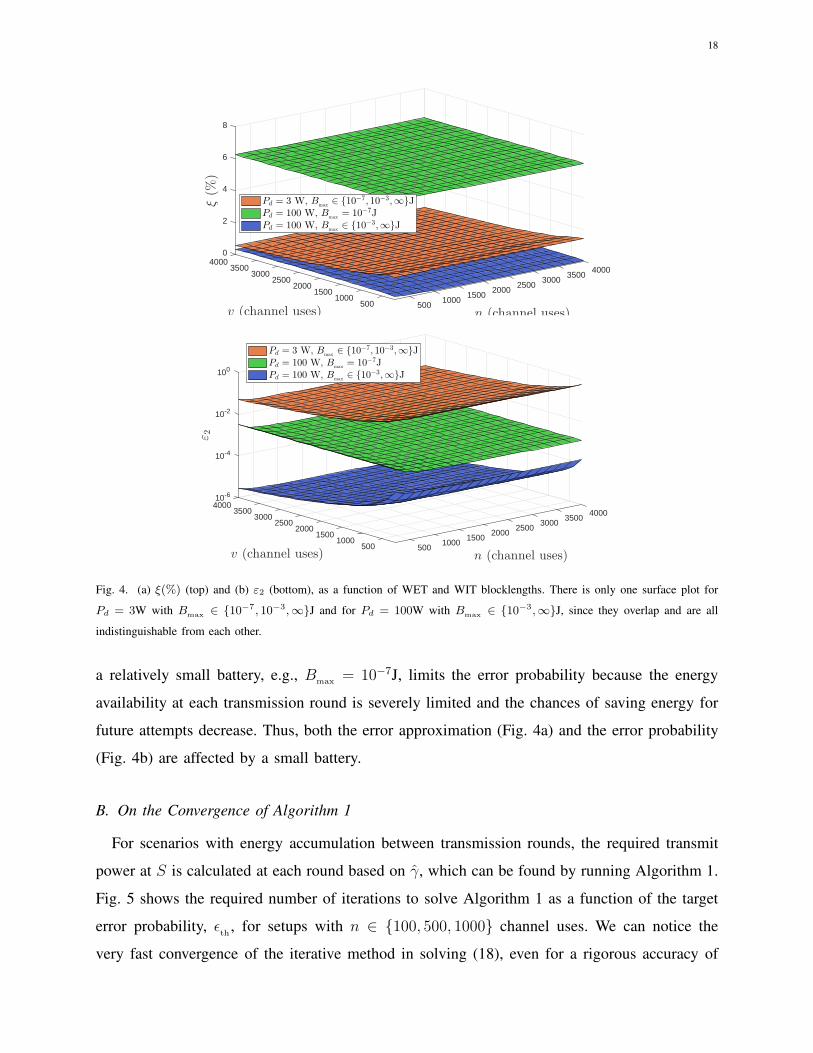
Fig. 4. (a) ξ(%) (top) and (b) ε2 (bottom), as a function of WET and WIT blocklengths. There is only one surface plot for
Pd = 3W with Bmax
∈ 10−7, 10−3,∞J and for Pd = 100W with Bmax
∈ 10−3,∞J, since they overlap and are all
indistinguishable from each other.
a relatively small battery, e.g., Bmax = 10−7J, limits the error probability because the energy
availability at each transmission round is severely limited and the chances of saving energy for
future attempts decrease. Thus, both the error approximation (Fig. 4a) and the error probability
(Fig. 4b) are affected by a small battery.
B. On the Convergence of Algorithm 1
For scenarios with energy accumulation between transmission rounds, the required transmit
power at S is calculated at each round based on γ, which can be found by running Algorithm 1.
Fig. 5 shows the required number of iterations to solve Algorithm 1 as a function of the target
error probability, ǫth
, for setups with n ∈ 100, 500, 1000 channel uses. We can notice the
very fast convergence of the iterative method in solving (18), even for a rigorous accuracy of
19
ǫth
10-9 10-7 10-5 10-3 10-1
iterations
0
1
2
3
4
5
6
7
8
9
10
n = 100 channel uses
n = 500 channel uses
n = 1000 channel uses
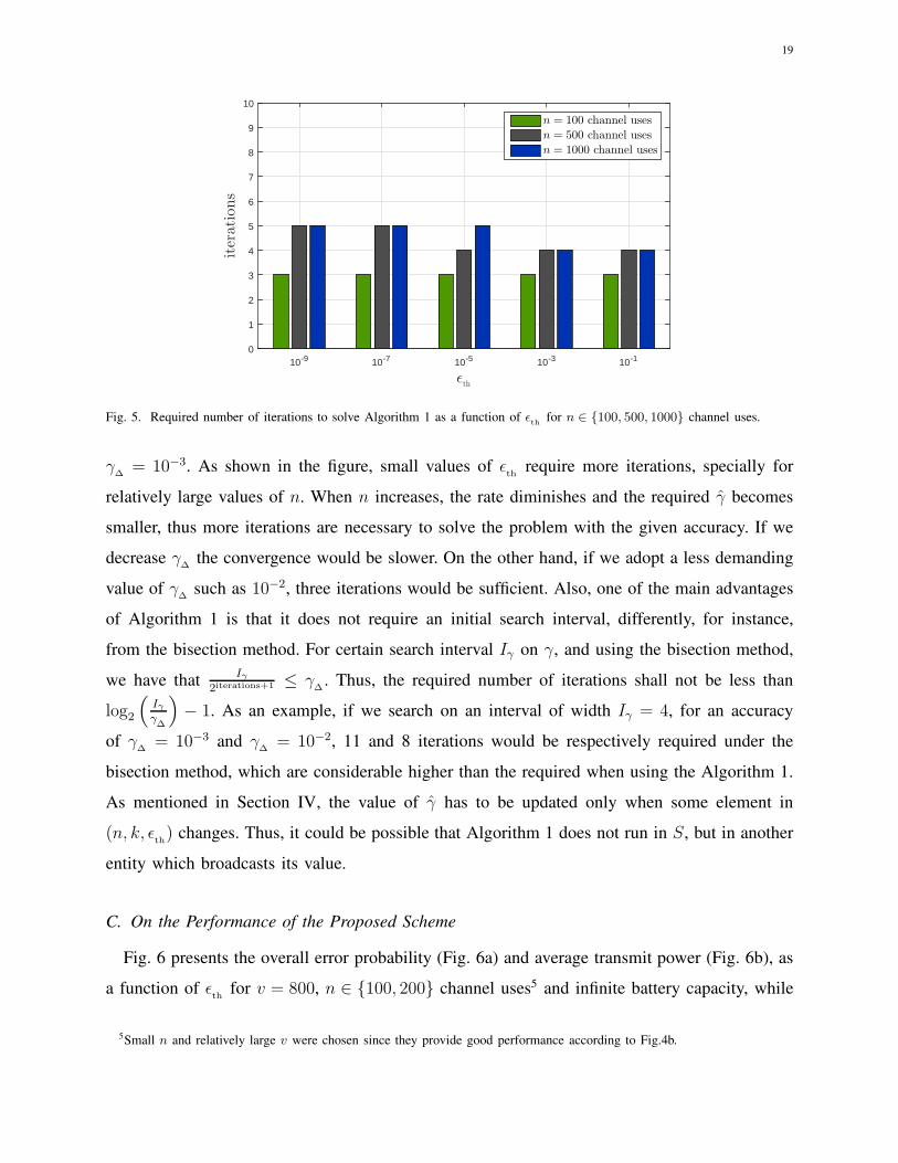
Fig. 5. Required number of iterations to solve Algorithm 1 as a function of ǫth
for n ∈ 100, 500, 1000 channel uses.
γ∆= 10−3. As shown in the figure, small values of ǫ
threquire more iterations, specially for
relatively large values of n. When n increases, the rate diminishes and the required γ becomes
smaller, thus more iterations are necessary to solve the problem with the given accuracy. If we
decrease γ∆
the convergence would be slower. On the other hand, if we adopt a less demanding
value of γ∆
such as 10−2, three iterations would be sufficient. Also, one of the main advantages
of Algorithm 1 is that it does not require an initial search interval, differently, for instance,
from the bisection method. For certain search interval Iγ on γ, and using the bisection method,
we have thatIγ
2iterations+1 ≤ γ∆
. Thus, the required number of iterations shall not be less than
log2
(Iγγ∆
)
− 1. As an example, if we search on an interval of width Iγ = 4, for an accuracy
of γ∆
= 10−3 and γ∆
= 10−2, 11 and 8 iterations would be respectively required under the
bisection method, which are considerable higher than the required when using the Algorithm 1.
As mentioned in Section IV, the value of γ has to be updated only when some element in
(n, k, ǫth) changes. Thus, it could be possible that Algorithm 1 does not run in S, but in another
entity which broadcasts its value.
C. On the Performance of the Proposed Scheme
Fig. 6 presents the overall error probability (Fig. 6a) and average transmit power (Fig. 6b), as
a function of ǫth
for v = 800, n ∈ 100, 200 channel uses5 and infinite battery capacity, while
5Small n and relatively large v were chosen since they provide good performance according to Fig.4b.

20
10-8 10-7 10-6 10-5 10-4 10-3 10-2 10-1 100
ǫth
10-5
10-4
10-3
10-2
10-1
100
εHTT, n = 100 channel usesFB-FTUT, n = 100 channel usesFB-FTT, n = 100 channel usesHTT, n = 200 channel usesFB-FTUT, n = 200 channel usesFB-FTT, n = 200 channel usesUsing approximation (11)
10-8 10-7 10-6 10-5 10-4 10-3 10-2 10-1 100
ǫth
-21
-20
-19
-18
-17
-16
-15
P(dBm)
HTT, n = 100 channel usesFB-FTUT, n = 100 channel usesFB-FTT, n = 100 channel usesHTT, n = 200 channel usesFB-FTUT, n = 200 channel usesFB-FTT, n = 200 channel uses
Fig. 6. (a) ε (top) and (b) P (bottom), as a function of ǫth
for v = 800 and n ∈ 100, 200 channel uses with Bmax
= ∞.
comparing the three protocols previously discussed: HTT (Section III), FB-FTT and FB-FTUT
(Section IV). In Fig 6a it is shown the existence and uniqueness of the optimum value of ǫth
for
the FB-FTT protocol6, which supports the claim made in Subsection IV-B. The FB-FTT scheme
has the best performance for practical scenarios, e.g., ǫth< 10−1, although the difference when
comparing to FB-FTUT becomes smaller for relatively large values of n. For n = 200 channel
uses, the system has the best performance, thus ǫ∗th
is the smallest. In that case, the power
control curves almost reach the allowable limit of ε = 10−5 for ǫth= 10−5. Notice that when n
increases, the required SNR and therefore the transmit power become smaller, and even when
S spends more time transmitting, the energy consumption decreases as shown in Fig 6b. This
6Also notice that if we draw the FB-FTT overall error performance on linear scale axes, the convexity becomes clear.

21
10 15 20 25 30 35 40 45 50
Pd (dBm)
10-7
10-6
10-5
10-4
10-3
10-2
10-1
100
ε HTT, Bmax
= 10−7JHTT, B
max= 10−5J
HTT, Bmax
= 10−3JHTT, B
max= ∞
FB-FTT, Bmax
= 10−7JFB-FTT, B
max= 10−5J
FB-FTT, Bmax
= 10−3JFB-FTT, B
max= ∞
20 25 30 35 40 45 50
Pd (dBm)
-60
-50
-40
-30
-20
-10
0
P(dBm)
HTT, Bmax
= 10−7JHTT, B
max= 10−5J
HTT, Bmax
= 10−3JHTT, B
max= ∞
FB-FTT, Bmax
= 10−7JFB-FTT, B
max= 10−5J
FB-FTT, Bmax
= 10−3JFB-FTT, B
max= ∞
Fig. 7. System performance as a function of Pd, (a) ε (top) and (b) P (bottom), for Bmax
∈ 10−7, 10−5, 10−3,∞J,
ǫth
= 10−6 and v = 800, n = 200 channel uses.
holds until certain n, n∗, and beyond that the weight of the transmitting time is more relevant
than the small transmit power. Decreasing ǫth
allows saving more energy while the average
transmit power decreases as shown in Fig. 6b, however the error performance is bounded by
this value. Notice also that the average transmit power, and consequently the average energy
consumption, is practically the same for both FB-FTT and FB-FTUT strategies, thus FB-FTT is
more energy efficient since it allows reaching a better error performance. Finally, we can note
the remarkable performance gap between HTT and the power control protocols, which reinforces
the appropriateness of the idea behind saving energy between transmission rounds.
In Fig. 7 we evaluate the impact of battery capacity, Bmax ∈ 10−7, 10−5, 10−3,∞J, while
comparing the performance of HTT and FB-FTT protocols in terms of ε (Fig. 7a) and P (Fig. 7b)

22
100 200 300 400 500 600 700 800 900 1000
n (channel uses)
10-8
10-6
10-4
10-2
100
ε
m = 3
m = 4
m = 2
HTTFB-FTT, ǫ
th= 10−3
FB-FTT, ǫth= 10−6
FB-FTT, ǫth= 10−9
Using approximation (10)
m = 2, 3, 4
Fig. 8. ε as a function of n for ǫth
∈ 10−3, 10−6, 10−9, Bmax
= 10−3J and fixed delay n + v = 1000 channel uses. In
addition to curves for m = 2, we also plot HTT and FB-FTT with ǫeth
= 10−9 for m = 3, 4.
as a function of Pd, for εth= 10−6 and v = 800, n = 200 channel uses. As shown in Fig. 7a,
the impact of a finite battery capacity on the error performance is insignificant for the HTT
protocol since there is no energy accumulation between transmission rounds. Therefore, only
when a high amount of energy is being transferred, e.g., Pd > 50dBm, the gap should start
to be appreciable. However, for the FB-FTT scheme the situation is more delicate since the
larger the battery capacity, the greater the chances to save more energy for future transmissions,
thus the better the error performance (Fig. 7a) and the larger the average energy consumption
(Fig. 7b). Notice the small system performance gap between setups with Bmax = 10−3J and
Bmax = ∞, and this is due to the small amount of energy being harvested in these setups with
short WET phase. It is evident that for Pd > 30dBm we have ǫ∗th
< 10−6, since the system
setup favors a better performance. In that case the gap between Bmax = 10−3J and Bmax = ∞becomes more significant since more energy is being transfered. Also, the overall error probability
improves for Pd < 30dBm if we choose a smaller target error probability. The average transmit
power for HTT protocol remains almost constant around P = −13dBm for Bmax = 10−7J and
Pd > 40dBm since E[Ei] > Bmax , e.g., E[Ei]∣∣Pd=40dBm
≈ 10−7J, thus Bi ≈ Bmax and according
to (5) Ps,i ≈ 10−7J200×10−5s
= 5× 10⁻⁵ → −13dBm, both holding almost all the time. The FB-FTT
protocol reaches an even small energy consumption since it does not spend all the available
energy in each round, specially when channel conditions are favorable.
In Fig. 8 we fix the system delay in delivering each message by setting n + v = 1000

23
channel uses, e.g., 1000Tc = 10ms, which could be fundamental in systems with very stringent
delay constraints, such as Ultra-Reliable Communication over Short Term (URC-S) scenarios for
future wireless systems [30]. Results are given as a function of n, for ǫth∈ 10−3, 10−6, 10−9
and Bmax = 10−3J. In URC-S scenarios, a high reliability is also required, which could be
achieved via the proposed FB-FTT scheme as shown here. Notice that, even for very good
channel conditions like m = 4, HTT performs poorly all the time, e.g., ε > 10−1; while with the
appropriate chosen value of ǫth
, the FB-FTT protocol can offer a much better performance. Focus
first on the m = 2 setup and observe that the FB-FTT protocol achieves an error probability
around ε = 10−6 for n ∼ 350 channel uses. Also, when n ≥ 400 channel uses, a target error
probability greater than 10−6 is required in order to achieve the optimum system performance.
Then, n∗ ∼ 350, v∗ ∼ 650 channel uses are approximately the optimum values for reaching the
target error ǫ∗th∼ 10−6 within the given delay constraint of 1000 channel uses in channels with
m = 2. In scenarios where channels have a larger influence of the line of sight, m, the chances
of success are greater, because it is likely that more energy will be harvested in the downlink
each time and stored for future energy-demanding transmissions7. The greater m, the smaller the
optimum target error. In fact, and according to Fig. 8, it is expected that 10−8 < ǫ∗th< 10−9. All
these results clearly show the convenience of a joint optimization of n, v and ǫth
. Notice that
an off-line optimization, which yields optimum parameters a priori and valid for long periods,
seems more convenient for energy-constrained setups since it avoids the interchange of additional
information between the nodes.
Finally, results in Figs. 6a and 8 corroborate the accuracy of expressions (10) and (11), claimed
when discussing Fig. 4a.
VI. CONCLUSION
In this paper, we evaluated a point-to-point communication system at finite blocklength regime
with WET in the downlink, WIT in the uplink and a finite battery capacity. We attained closed-
form expressions for error probability and average transmit power in scenarios where energy
accumulation between transmission rounds are allowed or not, Nakagami-m reciprocal channels
are assumed, and the sensitivity of the energy harvester is taken into account. For scenarios
allowing energy accumulation we propose a power control protocol with CSI at the transmitter
7Pd and m impact similarly on the system performance because of that.

24
side, which can be seen as a variant for finite blocklength of the FTT scheme [27]. The numerical
results show that
• the closed-form approximations for the case without energy accumulation between trans-
mission rounds (HTT protocol), under the assumption of finite and infinite battery devices,
are pretty accurate when batteries are not extremely small;
• saving energy for future transmissions (FB-FTT scheme) allows to improve the system
performance in terms of error probability while reducing the energy consumption;
• the proposed iterative method (Algorithm 1), which allows to find the required SNR for a
target error probability, converges very fast;
• the optimum system performance depends on the chosen target error probability value,
which in turns depends on the remaining system parameters;
• there is an optimum value of target error probability that minimizes the achievable error
probability. However, the higher the target error probability, the lower the energy consump-
tion;
• a relatively small battery could be a limiting factor for some setups and specially for
scenarios allowing energy accumulation between transmission rounds.
As a future work we intend to analyze the impact of imperfect CSI, while considering the
additional delay and the energy consumption required for CSI acquisition. In addition, it could
be interesting to incorporate power allocation strategies in WPCN with HARQ or/and cooperative
mechanisms with finite blocklength.
APPENDIX A
PROOF OF THEOREM 1
Let I1 and I2 be the first and second integral in (8), respectively. Then, and accordingly to
(9), µ1 = β, t = 2 for I1 and µ2 = βλ, t = 1 for I2.
Substituting (9) into (8), I1 can be approximated as follows
I1 ≈∫ z11
z13
fG(g)dg + ω1
∫ z12
z14
fG(g)dg − ω2
∫ z12
z14
g2fG(g)dg
(a)≈ FG(z11)− FG(z13) + ω1FG(z12)− ω1FG(z14)− ω2
∫ z12
z14
mm
Γ(m)gm+1e−mgdg
(b)≈ 1
Γ(m)
[
Γ(m,mz13
)− Γ
(m,mz11
)+ ω1
(
Γ(m,mz14
)− Γ
(m,mz12
))
+
+ω2
m2
(
Γ(m+ 2, mz12
)− Γ
(m+ 2, mz14
))]
, (29)

25
where (a) comes from using the CDF definition of a random variable along with substituting the
PDF of G in the last term. In (b), the CDF expression of G is used, while the last term comes
from algebraic transformations of the incomplete gamma function definition [56, eq.(8.2.1)].
Similarly to I1, I2 can be approximated as follows
I2 ≈∫ z21
z23
fG(g)dg+ω1
∫ z22
z21
fG(g)dg−ω2z23
∫ z22
z21
gfG(g)dg
≈ FG(z21)− FG(z23) + ω1FG(z22)− ω1FG(z21)− ω2z23
∫ z22
z21
mm
Γ(m)gme−mgdg
≈ 1
Γ(m)
[
(ω1 − 1)Γ(m,mz21
)+ Γ
(m,mz23
)− ω1Γ
(m,mz22
)+
+ω2z23m
(
Γ(m+ 1, mz22
)− Γ
(m+ 1, mz21
))]
. (30)
Then, substituting (29) and (30) into ε ≈ I1 + I2 (8) we attain (10). Now, notice that in the
case of infinite battery assumption, λ → ∞, ε ≈ I1 holds. Also, z11 = ζ1, z12 = ϕ1, z13 = z15
and z14 = z16 which allows to attain (11).
APPENDIX B
PROOF OF THEOREM 2
By using (5) and the PDF and CDF expressions of the channel gain g we attain
P = E[Ps,i] =
∫ ∞
0
Ps,ifG(gi)dg =ηvPd
nκdα
[ ∫ τ
∗
gfG(g)dg + λ
∫ ∞
τ
fG(g)dg
]
=ηvPd
nκdα
[mm
Γ(m)
∫ τ
∗
gme−mgdg + λ(1− FG(τ)
)]
(a)=
ηvPd
nκdα
[
− Γ(m+ 1, mg)
Γ(m+ 1)
∣∣∣∣
τ
∗
+ λΓ(m,mτ)
Γ(m)
]
, (31)
where the first term in (a) comes from algebraic transformations of the incomplete gamma
function definition [56, eq.(8.2.1)]. Showing that (31) is equivalent to (13) is straightforward.
Now, if Bmax = ∞ then
P∞ =E[Ps,i]=ηvPd
nκdα
∫ ∞
∗
gfG(g)dg=ηvPd
nκdα
[
−Γ(m+1, mg)
Γ(m+1)
]∣∣∣∣
∞
∗
=Γ(m+1, m∗)
Γ(m+1)
ηvPd
nκdα, (32)
which is equal to (13).

26
APPENDIX C
PROOF OF LEMMA 1
Finding γ reduces to solve (18), which could be stated as f(γ) = g(γ) − γ = 0, where
g(γ) = q1qM2 −1, M = M (∞) is a function of γ (20), q1 = 2r ≥ 1 since r ≥ 0, and q2 = e
Q−1(ǫth)√
n .
Note that f(γ) is continuous, while f(0) = q1 − 1 ≥ 0 and limγ→∞
f(γ) = −∞, thus there is at
least one γ such that f(γ) = 0. Based on the equation to solve, e.g., g(γ) = γ with γ ∈ R+,
we can argue as follows
• Case I: ǫeth
≥ 0.5
For this case Q−1(ǫth) ≤ 0, thus g(γ) is non-increasing and γ is increasing and there is
only one solution to g(γ) = γ.
• Case II: ǫeth
< 0.5
Now Q−1(ǫth) > 0, thus g(γ) is also increasing. Taking its derivatives we have
g′(γ) =q1q
M2 ln(q2)
(1 + γ)3M, (33)
g′′(γ) = − ln(q2)q1bM
M(1 + γ)2
[ 1
(1 + γ)2M+ 3− ln(q2)
(1 + γ)2
]
, (34)
where ln(q2) > 0. Thus, we can claim that g(γ) is concave if
1
(1 + γ)2M+ 3− ln(q2)
(1 + γ)2> 0 ⇒ q2 < e
1M
+3(1+γ)2
Q−1(ǫth) <
√n(
1M
+ 3(1 + γ)2)
ǫth> Q
(√n(
1M
+ 3(1 + γ)2))
, (35)
where the right side is maximized for the minimum value of√n(
1M
+ 3(1 + γ)2). Setting
n = 100, which is the minimum value for which all the analyses are valid, and γ = 0.1655,
which minimizes the remaining terms, we reach ǫth> Q(46.6364) ≈ 4.4×10−475. Evidently,
that requirement is met for any setup of practical interest. Thus, g(γ) is increasing and
concave and since g(0) > 0, which is the starting point of line γ, we conclude that they
intersect at one point only. Therefore, the solution is unique.
Thus, we can say that the unique solution, γ, is a fixed point of 2r+
M log2 eQ−1(ǫ
th)√
n − 1, e.g.,
γ = 2r+
M log2 eQ−1(ǫ
th)√
n −1 as shown in (19). Based on the Fixed Point Theory [57], if |g(γ)| < 1,

27
the fixed point iteration in (19) will converge to the solution. Using (33) evaluated on the solution
γ and performing some algebraic transformations, yields
|g′(γ)| =∣∣∣∣
q1qM2 ln(q2)
(1 + γ)3M
∣∣∣∣
(a)=
2reMQ−1(ǫ
eth)
√n
|Q−1(ǫeth
)|√n
(1 + γ)3M
(b)=
2relog2(1+γ)−r
log2 e | log2(1+γ)−r|M log2 e
(1 + γ)3M
(c)=
| log2(1 + γ)− r|γ(γ + 2) log2 e
, (36)
where (a) and (b) come from using the expressions of q1 and q2, and Q−1(ǫeth) = log2(1+γ)−r
M log2 e√
n
(see (7)), respectively; while (c) is attained after substituting M =√
1− 1(1+γ)2
followed by
some simplifications. Notice that for ǫeth
≤ 0.5, which is the case of practical interest, we have
that log2(1 + γ) ≥ r, thus
|g′(γ)| < log2(1 + γ)
γ(γ + 2) log2 e≤ ln 2 < 1, (37)
since log2(1+ γ) ≤ γ(γ+2) for γ ≥ 0. Therefore, and from Banach’s fixed point theorem [57],
the (at least) linear convergence of a Fixed-point iteration algorithm is guaranteed provided any
initial point γ(0). In this particular case, we chose γ(0) = ∞ → M (0) = 1. In Section V we show
that the proposed Algorithm 1 converges very fast for practical setups.
APPENDIX D
EVIDENCE OF UNIQUE OPTIMUM VALUE ǫ∗eth
Let ǫth
= x ∈ [0, 1], γ = z(x) ∈ R+, ǫout = s z = s(z(x)) ∈ [0, 1], where s(z) =
P[Bi < Ps,inTc] = P[gi < zχBi(z)
] = 1Γ(m)
Γ(m, mχz
Bi(z)
)with χ = κdασ2
dnTc, and ε = q(x) =
(1 − s(z(x)))x + s(z(x)) = x + (1 − x)s(z(x)) ∈ [0, 1] according to (21). We know that ǫout
is an increasing function, s, of z; however, z is decreasing on x, thus s is decreasing on x as
well. Also, s(z(0)) = 1 and s(z(1)) = 0, while q(0) = q(1) = 1. Notice that when ǫth
= 1,
the source S does not transmit and all it does is saving energy. In that case, the overall error
probability is the worst possible. When ǫth
decreases, S is required to transmit with more and
more power in order to fulfill the requirement. However, when ǫth
= 0 the required power is
practically impossible to reach and all that S can do is to save energy, similarly to the case when
ǫth
= 1, and again the error performance is the worst possible. Evidently there is an inflexion
point between ǫth= 0 and ǫ
th= 1, and now we aim at showing the singularity of this point.
Since every linear function is both convex and concave, we can say that x and 1−x are both
convex functions. If s(z(x)) is convex then we could say that q(x) is also convex on x ∈ [0, 1]

28
10-910-10
10-810-10
10-7
10-6
100
Λ
10-1110-5
x
10-4
q′′(x)
10-1210-3
1010
10-2
10-1310-1
1020
n = 100n = 500n = 1000
m = 0.5 ∗
m = 2 om = 10
Υ = 10−9
Υ = 10−8
Υ = 10−7
Υ = 10−6
Bmax = 10−7JBmax = ∞
Fig. 9. q′′(x) as a function of x for different values of system parameters Λ, Υ, Bmax
, n, m, and k = 312 bits.
and therefore the unique minimum would be guaranteed. This is because 1− x and s(z(x)) are
both convex decreasing functions, thus their product is convex [58], and the non-negative sum
of convex functions, e.g., (1 − x)s(z(x)) and x, is also convex [58]. Let’s now take a look at
the second derivative of s(z(x)):
s′(z(x)) = s′(z)z′(x)
s′′(z(x)) = s′′(z)z′(x)2 + s′(z)z′′(x), (38)
where z′(x)2 > 0, and s′(z) > 0 since s is an increasing function of z. We could even prove that
z′′(x) > 0 for x < 0.5, e.g., z(x) is convex on the region of interest, from some analysis based
on (19) and the fact that Q−1(x) is convex on that region. However, and based on many and
different setup simulations, since there is not an analytical expression of s(z), we come to the
conclusion that s′′(z) is not greater than 0 in all the cases. Therefore, s(z) is not always convex.
Thus, it becomes intractable finding analytical arguments in order to prove that s′′(z(x)) > 0
based on (38). In fact, our simulations show that s′′(z(x)) < 0 for few certain setups. However,
even in those cases the overall error probability, q(x), remains convex. Thus, the only path we
can follow is by means of simulations, while exploring as many different setups as possible.
Let Ei = Υgi1(gi ≥ ∗) with Υ = ηPdvTc
κdα, and Ps,inTc = Λ γn
giwith Λ = κdασ2
dTc, thus, Υ and
Λ influence on the amount of energy being harvested and used for transmission at S, respectively.
Also, a variation on η, Pd, v, Tc, κ, d, α, σ2d, could be modeled through a variation on Υ and/or

29
Λ. In Fig. 9, we show an estimated8 q′′(x) for the following system parameters: k = 312 bits,
Υ ∈ 10−9, 10−8, 10−7, 10−6, Λ ∈ 10−13, 10−12, 10−11, 10−10, 10−9, n ∈ 100, 500, 1000channel uses, m ∈ 0.5, 2, 10, Bmax ∈ 10−7,∞J. The values in bold are directed related
with the simulation parameters in Section V, and notice that the impact of different message
lengths, k, which conduces to different values of γ, could be also modeled through variations
on Λ. Notice that the convexity holds in every single case e.g., no curve presented a negative
value of q′′(x), thus the minimum is unique in the region of interest ǫeth
< 0.1.
APPENDIX E
PROOF OF THEOREM 3
The average power consumption of S can be computed as
P = (1− ǫout)E[Ps,i] = (1− ǫout)
∫ λ
0
Ps,ifG(g)dg(a)= (1− ǫout)γκd
ασ2d
∫ λ
0
mm
Γ(m)gm−2e−mgdg
(b)= −(1 − ǫout)γκd
ασ2dm
Γ(m− 1, mg)
Γ(m)
∣∣∣∣
λ
0
, (39)
where (a) comes from using (16), and (b) from algebraic transformations of the incomplete
gamma function definition [56, eq.(8.2.1)] with m > 1. We attain (22) straightforward from
(39). Now, substituting λ = ∞ into (39) yields
P∞ = −(1− ǫout)γκdασ2
dmΓ(m− 1, mg)
Γ(m)
∣∣∣∣
∞
0
= (1− ǫout)γκdασ2
dmΓ(m− 1, 0)
Γ(m), (40)
which is equal to (23).
REFERENCES
[1] E. Dahlman, G. Mildh, S. Parkvall, J. Peisa, J. Sachs, and Y. Selen, “5G radio access,” Ericsson review, vol. 6, pp. 2–7,
2014.
[2] P. Schulz, M. Matthe, H. Klessig, M. Simsek, G. Fettweis, J. Ansari, S. A. Ashraf, B. Almeroth, J. Voigt, I. Riedel,
A. Puschmann, A. Mitschele-Thiel, M. Muller, T. Elste, and M. Windisch, “Latency critical IoT applications in 5G:
Perspective on the design of radio interface and network architecture,” IEEE Communications Magazine, vol. 55, no. 2,
pp. 70–78, February 2017.
[3] A. Zanella, N. Bui, A. Castellani, L. Vangelista, and M. Zorzi, “Internet of things for smart cities,” IEEE IoT J., vol. 1,
no. 1, pp. 22–32, Feb 2014.
8The second derivative estimation was performed by collecting simulation data over 5× 10⁷ channel realizations for ǫeth
∈
10−8, 10−1 with spacing of 10−8 and applying numerical differentiation. Unfortunately, in order to acquire very accurate
measurements, since derivative estimations are very sensitive, we had to discard those parameter combinations leading to error
probabilities below 5× 10⁻⁵.

30
[4] D. Shaviv, P. M. Nguyen, and A. Ozgur, “Capacity of the energy-harvesting channel with a finite battery,” IEEE Transactions
on Information Theory, vol. 62, no. 11, pp. 6436–6458, Nov 2016.
[5] L. R. Varshney, “Transporting information and energy simultaneously,” in IEEE Int. Symp. on Inf. Theory, July 2008, pp.
1612–1616.
[6] P. Grover and A. Sahai, “Shannon meets tesla: Wireless information and power transfer,” in 2010 IEEE International
Symposium on Information Theory, June 2010, pp. 2363–2367.
[7] R. Zhang and C. K. Ho, “MIMO broadcasting for simultaneous wireless information and power transfer,” IEEE Transactions
on Wireless Communications, vol. 12, no. 5, pp. 1989–2001, May 2013.
[8] Powercast, 2015. [Online]. Available: http://www.powercastco.com/
[9] X. Lu, P. Wang, D. Niyato, D. I. Kim, and Z. Han, “Wireless networks with RF energy harvesting: A contemporary
survey,” IEEE Communications Surveys Tutorials, vol. 17, no. 2, pp. 757–789, 2015.
[10] H. Ju and R. Zhang, “Throughput maximization in wireless powered communication networks,” IEEE Transactions on
Wireless Communications, vol. 13, no. 1, pp. 418–428, January 2014.
[11] I. Krikidis, S. Timotheou, and S. Sasaki, “RF energy transfer for cooperative networks: Data relaying or energy harvesting?”
IEEE Communications Letters, vol. 16, no. 11, pp. 1772–1775, November 2012.
[12] B. Gurakan, O. Ozel, J. Yang, and S. Ulukus, “Energy cooperation in energy harvesting wireless communications,” in
2012 IEEE International Symposium on Information Theory Proceedings, July 2012, pp. 965–969.
[13] A. A. Nasir, X. Zhou, S. Durrani, and R. A. Kennedy, “Relaying protocols for wireless energy harvesting and information
processing,” IEEE Transactions on Wireless Communications, vol. 12, no. 7, pp. 3622–3636, July 2013.
[14] I. Krikidis, “Simultaneous information and energy transfer in large-scale networks with/without relaying,” IEEE Transac-
tions on Communications, vol. 62, no. 3, pp. 900–912, March 2014.
[15] Z. Ding, I. Krikidis, B. Sharif, and H. V. Poor, “Wireless information and power transfer in cooperative networks with
spatially random relays,” IEEE Transactions on Wireless Communications, vol. 13, no. 8, pp. 4440–4453, Aug 2014.
[16] G. L. Moritz, J. L. Rebelatto, R. D. Souza, B. F. Uchoa-Filho, and Y. Li, “Time-switching uplink network-coded cooperative
communication with downlink energy transfer,” IEEE Transactions on Signal Processing, vol. 62, no. 19, pp. 5009–5019,
Oct 2014.
[17] H. Chen, Y. Li, J. L. Rebelatto, B. F. Uchoa-Filho, and B. Vucetic, “Harvest-then-cooperate: Wireless-powered cooperative
communications,” IEEE Transactions on Signal Processing, vol. 63, no. 7, pp. 1700–1711, April 2015.
[18] A. A. Nasir, X. Zhou, S. Durrani, and R. A. Kennedy, “Wireless-powered relays in cooperative communications: Time-
switching relaying protocols and throughput analysis,” IEEE Transactions on Communications, vol. 63, no. 5, pp. 1607–
1622, May 2015.
[19] D. S. Michalopoulos, H. A. Suraweera, and R. Schober, “Relay selection for simultaneous information transmission and
wireless energy transfer: A tradeoff perspective,” IEEE Journal on Selected Areas in Communications, vol. 33, no. 8, pp.
1578–1594, Aug 2015.
[20] K. Xiong, P. Fan, C. Zhang, and K. B. Letaief, “Wireless information and energy transfer for two-hop non-regenerative
MIMO-OFDM relay networks,” IEEE Journal on Selected Areas in Communications, vol. 33, no. 8, pp. 1595–1611, Aug
2015.
[21] Z. Li, H. H. Chen, Y. Gu, Y. Li, and B. Vucetic, “Accumulate then forward: An opportunistic relaying protocol for wireless-
powered cooperative communications,” in 2016 24th European Signal Processing Conference (EUSIPCO), Aug 2016, pp.
813–817.
[22] Y. Gu, H. Chen, Y. Li, and B. Vucetic, “Wireless-powered two-way relaying with power splitting-based energy
accumulation,” in 2016 IEEE Global Communications Conference (GLOBECOM), Dec 2016, pp. 1–6.

31
[23] D. Mishra, S. De, and D. Krishnaswamy, “Dilemma at RF energy harvesting relay: Downlink energy relaying or uplink
information transfer?” IEEE Transactions on Wireless Communications, vol. 16, no. 8, pp. 4939–4955, Aug 2017.
[24] F. A. de Witt, R. D. Souza, and G. Brante, “On the performance of hybrid ARQ schemes for uplink information transmission
with wireless power transfer in the downlink,” in 2014 IFIP Wireless Days (WD), Nov 2014, pp. 1–6.
[25] K. Huang and E. Larsson, “Simultaneous information and power transfer for broadband wireless systems,” IEEE
Transactions on Signal Processing, vol. 61, no. 23, pp. 5972–5986, Dec 2013.
[26] L. Liu, R. Zhang, and K. C. Chua, “Wireless information and power transfer: A dynamic power splitting approach,” IEEE
Transactions on Communications, vol. 61, no. 9, pp. 3990–4001, September 2013.
[27] A. Isikman, M. Yuksel, and D. Gunduz, “A low-complexity policy for outage probability minimization with an energy
harvesting transmitter,” IEEE Communications Letters, vol. PP, no. 99, pp. 1–1, 2016.
[28] B. Makki, T. Svensson, and M. Zorzi, “Wireless energy and information transmission using feedback: Infinite and finite
block-length analysis,” IEEE Transactions on Communications, vol. 64, no. 12, pp. 5304–5318, Dec 2016.
[29] T. A. Khan, R. W. Heath, and P. Popovski, “On wirelessly powered communications with short packets,” in 2016 IEEE
Globecom Workshops (GC Wkshps), Dec 2016, pp. 1–6.
[30] G. Durisi, T. Koch, and P. Popovski, “Toward massive, ultrareliable, and low-latency wireless communication with short
packets,” Proceedings of the IEEE, vol. 104, no. 9, pp. 1711–1726, Sept 2016.
[31] Y. Polyanskiy, H. V. Poor, and S. Verdu, “Channel coding rate in the finite blocklength regime,” IEEE Trans. Inf. Theory,
vol. 56, no. 5, pp. 2307–2359, May 2010.
[32] W. Yang, G. Durisi, T. Koch, and Y. Polyanskiy, “Quasi-static SIMO fading channels at finite blocklength,” in IEEE Int.
Symp. on Inf. Theory Proc. (ISIT), July 2013, pp. 1531–1535.
[33] Y. Polyanskiy, H. V. Poor, and S. Verdu, “Feedback in the non-asymptotic regime,” IEEE Transactions on Information
Theory, vol. 57, no. 8, pp. 4903–4925, Aug 2011.
[34] V. Kostina and S. Verdu, “Lossy joint source-channel coding in the finite blocklength regime,” IEEE Transactions on
Information Theory, vol. 59, no. 5, pp. 2545–2575, May 2013.
[35] W. Yang, G. Durisi, T. Koch, and Y. Polyanskiy, “Diversity versus channel knowledge at finite block-length,” in 2012
IEEE Information Theory Workshop, Sept 2012, pp. 572–576.
[36] G. Durisi, T. Koch, J. Ostman, Y. Polyanskiy, and W. Yang, “Short-packet communications over multiple-antenna rayleigh-
fading channels,” IEEE Transactions on Communications, vol. 64, no. 2, pp. 618–629, Feb 2016.
[37] P. Mary, J.-M. Gorce, A. Unsal, and H. V. Poor, “Finite block length information theory: What is the practical impact on
wireless communications?” in IEEE Global Communications Conference - Workshops: First IEEE International Workshop
on Low-Layer Implementation and Protocol Design for IoT Applications, Washington, DC, USA, Dec 2016.
[38] O. L. A. Lopez, H. Alves, R. D. Souza, and E. M. G. Fernandez, “Ultrareliable short-packet communications with wireless
energy transfer,” IEEE Signal Processing Letters, vol. 24, no. 4, pp. 387–391, April 2017.
[39] O. L. A. Lopez, R. D. Souza, H. Alves, and E. M. G. Fernandez, “Ultra reliable short message relaying with wireless
power transfer,” in 2017 IEEE International Conference on Communications (ICC), May 2017, pp. 1–6.
[40] A. Guo, H. Yin, and W. Wang, “Performance analysis of energy harvesting wireless communication system with finite
blocklength,” IEEE Communications Letters, vol. 20, no. 2, pp. 324–327, Feb 2016.
[41] A. Tandon, M. Motani, and L. R. Varshney, “Subblock energy-constrained codes for simultaneous energy and information
transfer,” in 2016 IEEE Int. Symp. on Inf. Theory (ISIT), July 2016, pp. 1969–1973.
[42] M. Haghifam, B. Makki, M. Nasiri-Kenari, T. Svensson, and M. Zorzi, “Wireless-powered relaying with finite block-length
codes,” arXiv preprint arXiv:1611.05995, 2016.

32
[43] G. Lechner, K. D. Nguyen, A. G. I. Fabregas, and L. K. Rasmussen, “Optimal power control for LDPC codes in block-
fading channels,” IEEE Transactions on Communications, vol. 59, no. 7, pp. 1759–1765, July 2011.
[44] M. C. Gursoy, “Throughput analysis of buffer-constrained wireless systems in the finite blocklength regime,”
EURASIP Journal on Wireless Communications and Networking, vol. 2013, no. 1, p. 290, 2013. [Online]. Available:
http://dx.doi.org/10.1186/1687-1499-2013-290
[45] W. Yang, G. Caire, G. Durisi, and Y. Polyanskiy, “Optimum power control at finite blocklength,” IEEE Transactions on
Information Theory, vol. 61, no. 9, pp. 4598–4615, Sept 2015.
[46] M. Guillaud, D. T. Slock, and R. Knopp, “A practical method for wireless channel reciprocity exploitation through relative
calibration.” in ISSPA, 2005, pp. 403–406.
[47] F. Zhao, L. Wei, and H. Chen, “Optimal time allocation for wireless information and power transfer in wireless powered
communication systems,” IEEE Transactions on Vehicular Technology, vol. 65, no. 3, pp. 1830–1835, March 2016.
[48] Z. Hadzi-Velkov, I. Nikoloska, G. K. Karagiannidis, and T. Q. Duong, “Wireless networks with energy harvesting and
power transfer: Joint power and time allocation,” IEEE Signal Processing Letters, vol. 23, no. 1, pp. 50–54, Jan 2016.
[49] G. Yang, C. K. Ho, R. Zhang, and Y. L. Guan, “Throughput optimization for massive MIMO systems powered by wireless
energy transfer,” IEEE Journal on Selected Areas in Communications, vol. 33, no. 8, pp. 1640–1650, Aug 2015.
[50] A. Goldsmith, Wireless communications. Cambridge university press, 2005.
[51] D. P. Bertsekas, R. G. Gallager, and P. Humblet, Data networks. Prentice-Hall International New Jersey, 1992, vol. 2.
[52] Y. Hu, A. Schmeink, and J. Gross, “Blocklength-limited performance of relaying under quasi-static rayleigh channels,”
IEEE Trans. Wireless Commun., vol. 15, no. 7, pp. 4548–4558, July 2016.
[53] W. Yang, G. Durisi, T. Koch, and Y. Polyanskiy, “Quasi-static multiple-antenna fading channels at finite blocklength,”
IEEE Transactions on Information Theory, vol. 60, no. 7, pp. 4232–4265, July 2014.
[54] B. Makki, T. Svensson, and M. Zorzi, “Finite block-length analysis of the incremental redundancy HARQ,” IEEE Wireless
Commun. Lett., vol. 3, no. 5, pp. 529–532, Oct 2014.
[55] G. Papotto, F. Carrara, and G. Palmisano, “A 90-nm CMOS threshold-compensated RF energy harvester,” IEEE Journal
of Solid-State Circuits, vol. 46, no. 9, pp. 1985–1997, Sept 2011.
[56] W. Frank, W. Daniel, F. Ronald, and W. Charles, “NIST handbook of mathematical functions,” Cambridge University
Press, New York, USA, ISBN, vol. 521140633, p. 9780521140638, 2010.
[57] R. P. Agarwal, M. Meehan, and D. O’Regan, Fixed point theory and applications. Cambridge university press, 2001,
vol. 141.
[58] S. Boyd and L. Vandenberghe, Convex optimization. Cambridge university press, 2004.