wireless sensor networks in a vehicle environment
TRANSCRIPT

Department of Computer Science and Engineering CHALMERS UNIVERSITY OF TECHNOLOGY UNIVERSITY OF GOTHENBURG Göteborg, Sweden, December 2009
Wireless Sensor Networks in a Vehicle Environment Master of Science Thesis
RAFAEL BASSO

The Author grants to Chalmers University of Technology and University of Gothenburg the non-exclusive right to publish the Work electronically and in a non-commercial purpose make it accessible on the Internet. The Author warrants that he/she is the author to the Work, and warrants that the Work does not contain text, pictures or other material that violates copyright law. The Author shall, when transferring the rights of the Work to a third party (for example a publisher or a company); acknowledge the third party about this agreement. If the Author has signed a copyright agreement with a third party regarding the Work, the Author warrants hereby that he/she has obtained any necessary permission from this third party to let Chalmers University of Technology and University of Gothenburg store the Work electronically and make it accessible on the Internet.
Wireless sensor networks in a vehicle environment RAFAEL BASSO © RAFAEL BASSO, December 2009. Examiner: LARS BENGTSSON Department of Computer Science and Engineering Chalmers University of Technology SE-412 96 Göteborg Sweden Telephone + 46 (0)31-772 1000 Department of Computer Science and Engineering Göteborg, Sweden December 2009
Abstract A wireless sensor network is composed of autonomous distributed sensors that cooperate to monitor physical conditions. In a vehicle these conditions can be tire pressure, cargo temperature, trailer door status, presence detection and others. Furthermore, with this technology available in vehicles, many other applications can be implemented for the truck, driver and dispatcher like remote keyless entry, remote control and much more. The final benefits are safer, securer and more efficient operations. The objective of this thesis work carried out at Volvo Technology AB was to implement and evaluate a prototype solution for wireless sensor networks in vehicles. Volvo has developed the Telematics Gateway, which is a device that is installed in the trucks to collect information from the vehicle, log and send this information to a web portal. Therefore the main objective of this project was to integrate wireless sensors with the Telematics Gateway. The technology chosen for the wireless network is Zigbee. In order to have a complete system, wireless sensor prototypes were also developed. Additionally an evaluation was prepared for the hardware and cost needed to incorporate Zigbee networks into the Telematics Gateway circuit board.

Acknowledgements This master thesis has been a great team effort since different departments at Volvo Technology AB were involved and also Datachassi AB took part in the project. Without the engagement of all the interested parts it would not have been possible to achieve a successful result in the end. I would like to thank my examiner Lars Bengtsson who first of all suggested this master thesis, then agreed to work with me and assisted me when I needed. Special thanks to my two supervisors at Volvo, Pontus All who chose me for the job, guided me through the first steps and believed in my work, and Fredrik Bode who was always available to help me and supported me during the last steps of the project. I would like also to express my deepest gratitude to Ignacio Mancha and Per Olof Näfverborn at Datachassi, for the excellent team work, timely responses and for being exceptionally cooperative with me. My thanks extend to Werner Hilliges as well. Thanks also to my colleagues at Volvo: Dorreh Dormishian who shared the introductory part of the project with me; Martin Hansson for helping me learning Rhapsody and answering all my questions; Daniel Eriksson for the support with the TGW issues and for developing the business layer of the software; Patrik Stenberg and Sven Claesson who developed the web portal part of the application; Torbjörn Alsätra and Otto Emanuelsson who were also part of the project. My appreciation goes to all other colleagues at Volvo who somehow helped, or simply were there to chat while having a coffee in a “fika” time. I believe that it is impossible to do anything completely alone, so without all these persons I would not have been able to carry out this work. Last but not least, a very special thanks to Teresinha, Eloi, Aline, Gabriel and Jessica for the unconditional support and love.
Table of Contents Definitions, acronyms and abbreviations .................................................................... 8
1. Introduction ............................................................................................................. 9 1.1. Background ...................................................................................................... 9 1.2. Problem description ....................................................................................... 10
1.2.1. Fleet Management Platform and the TGW .............................................. 10 1.2.2. Datachassi sensors ................................................................................. 10
1.2.3. Zigbee protocol ........................................................................................ 11 1.3. Expected results ............................................................................................ 11
2. Methodology and Tools ........................................................................................ 13
2.1. UML ............................................................................................................... 13 2.1.1. Structure Diagrams .................................................................................. 14 2.1.2. Behavior Diagrams .................................................................................. 14
2.2. Rhapsody ....................................................................................................... 14
2.3. TGW Software ............................................................................................... 17 2.4. Sensors .......................................................................................................... 18
3. Initiation and Planning .......................................................................................... 20 3.1. Scope ............................................................................................................. 20
3.2. Delimitations .................................................................................................. 21 3.3. Stakeholders .................................................................................................. 21 3.4. Risks .............................................................................................................. 22
3.5. Schedule ........................................................................................................ 23
4. Analysis and Design ............................................................................................. 25 4.1. Requirements ................................................................................................. 25 4.2. System model ................................................................................................ 26
4.3. Protocol specification ..................................................................................... 27 4.3.1. Zigbee protocol ........................................................................................ 27
4.3.2. uGW protocol........................................................................................... 29 4.3.3. Sensors protocol ...................................................................................... 29
5. Implementation ..................................................................................................... 30
5.1. TGW software ................................................................................................ 30 5.1.1. DPM Layer .............................................................................................. 30
5.1.1.1. Link Layer ......................................................................................... 31
5.1.1.2. Data Layer ........................................................................................ 31
5.1.1.3. APS Layer and Primitives ................................................................. 32 5.1.1.4. ZDO Application and Commands ...................................................... 36 5.1.1.5. Endpoints, Devices and Groups ........................................................ 38 5.1.1.6. ZCL Frame ........................................................................................ 40 5.1.1.7. Module Interface ............................................................................... 41
5.1.1.8. Debug and Serial Port ....................................................................... 42 5.1.1.9. Tests ................................................................................................. 43
5.1.2. Core Layer ............................................................................................... 44 5.1.2.1. Zigbee Cluster Library ....................................................................... 44 5.1.2.2. Applications....................................................................................... 45
5.1.2.3. Sensors ............................................................................................. 47 5.1.2.4. Module Interface ............................................................................... 52 5.1.2.5. Persistent data .................................................................................. 53 5.1.2.6. Tests ................................................................................................. 53
5.2. Hardware ....................................................................................................... 53
5.2.1. uGW prototype ........................................................................................ 54 5.3. Sensor prototypes .......................................................................................... 55
5.3.1. Door sensor simulator ............................................................................. 56
5.3.2. Movable panic button .............................................................................. 57 5.3.3. Temperature sensor ................................................................................ 57
6. Verification and Tests ........................................................................................... 58 6.1. General tests .................................................................................................. 58 6.2. Sensor tests ................................................................................................... 59
7. Closing.................................................................................................................. 60 7.1. Hardware proposal ......................................................................................... 60 7.2. Cost estimation .............................................................................................. 60
8. Conclusions .......................................................................................................... 61
8.1. Future Work ................................................................................................... 61 References ............................................................................................................... 62 Appendixes ............................................................................................................... 64 I. TGW Description ............................................................................................... 64
II. Communication Protocol ................................................................................... 65 III. Sensors protocol ............................................................................................... 73 IV. Example of frames ............................................................................................ 74
V. Communication log (TGW, uGW and E-Seal) ................................................... 77 VI. Circuit Schematic .............................................................................................. 82 VII. Bill of Materials .................................................................................................. 83
List of Figures Figure 1 – Datachassi modified lamps ...................................................................... 11
Figure 2 – Class Diagram ......................................................................................... 15 Figure 3 – Statechart ................................................................................................ 16 Figure 4 – Different views of the Features window ................................................... 17 Figure 5 – Atmel Raven kit ....................................................................................... 18 Figure 6 – AVR JTAGICE mkII ................................................................................. 18
Figure 7 – AVR Studio 4 ........................................................................................... 19 Figure 8 – TGW and uGW connection overview ....................................................... 20 Figure 9 – TGW, uGW and E-Seal ........................................................................... 20
Figure 10 – Project schedule .................................................................................... 24 Figure 11 – System model overview ......................................................................... 26 Figure 12 – Outline of the Zigbee Stack Architecture ............................................... 28 Figure 13 – DPM layer overview ............................................................................... 30
Figure 14 – Link layer frame format (in yellow) ......................................................... 31 Figure 15 – LinkLayer statechart .............................................................................. 31 Figure 16 – Data layer frame format (in blue) ........................................................... 31 Figure 17 – Data layer ack/nack frame format (in blue) ............................................ 31
Figure 18 – DataLayer statechart ............................................................................. 32 Figure 19 – APS primitive classes ............................................................................ 33 Figure 20 – APSLayer statechart .............................................................................. 34
Figure 21 – ZDO and commands ............................................................................. 37
Figure 22 – ZDOApplication statechart ..................................................................... 38 Figure 23 – Endpoint classes ................................................................................... 39 Figure 24 – ZCLFrame class .................................................................................... 41
Figure 25 – Module interface .................................................................................... 42 Figure 26 – Test class .............................................................................................. 43
Figure 27 – Cluster classes ...................................................................................... 45 Figure 28 – Read response command classes ......................................................... 45 Figure 29 – Application and ZCL classes ................................................................. 46
Figure 30 – ZigbeeApplication statechart ................................................................. 47 Figure 31 – ESealFactory composite class............................................................... 48
Figure 32 – E-Seal sensor class and interface ......................................................... 49
Figure 33 – ESealDevice statechart ......................................................................... 50
Figure 34 – WirelessSensorsMng class and interfaces ............................................ 52 Figure 35 – Atmel EVK1101 ..................................................................................... 54 Figure 36 – RCB231ED ............................................................................................ 54 Figure 37 – uGW Prototype ...................................................................................... 55 Figure 38 – TGW unit ............................................................................................... 58
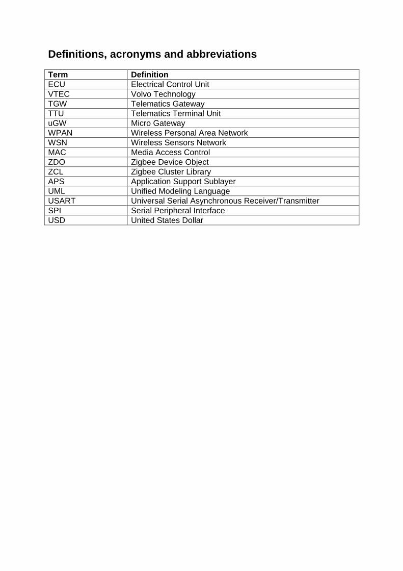
Definitions, acronyms and abbreviations
Term Definition
ECU Electrical Control Unit
VTEC Volvo Technology
TGW Telematics Gateway
TTU Telematics Terminal Unit
uGW Micro Gateway
WPAN Wireless Personal Area Network
WSN Wireless Sensors Network
MAC Media Access Control
ZDO Zigbee Device Object
ZCL Zigbee Cluster Library
APS Application Support Sublayer
UML Unified Modeling Language
USART Universal Serial Asynchronous Receiver/Transmitter
SPI Serial Peripheral Interface
USD United States Dollar

1. Introduction A vehicle and its environment are increasingly connected. Different parts of the vehicle, road infrastructure, other vehicles and dispatchers are getting connected and able to gather and distribute data, which could be used to enable better operations. Sensor networks of various kinds are of high interest due to potentially many vehicle applications. Today, functionality is limited by expensive installation and harnessing, which could be reduced by the introduction of wireless sensor networks. The challenge is at the same time to transform the capabilities of sensor networks to be useful services for the truck, driver and its dispatcher.
1.1. Background In January 2008 an internal report [1] was issued at Volvo Technology (VTEC) with a feasibility study of implementing a Common Wireless Gateway for vehicle sensors. According to this report, there are many reasons why such a system is desirable. Among them we can cite reduced costs by not having a harness, easier installation of new sensors and high flexibility to add current and future systems. The applications include a broad range of devices such as remote keyless entry, remote control, tire pressure monitoring, wireless accessories etc. But one of the highlighted applications was truck and trailer communication since there are many advantages of using this feature. On the other hand, it is not commonly used nowadays mainly because there is no “de-facto” standard and wires are a complication for this system. The final conclusion of the Common Wireless Gateway report was that at this moment a completely new Common Wireless Gateway was not economically feasible. The recommendation was to add this functionality in an existing Electrical Control Unit (ECU) in the vehicle. Following this recommendation, it was decided that the Volvo Telematics Gateway (TGW) would be the one to have the wireless interface. Nonetheless the technologies to be used were not chosen completely according to the recommendations in this report, but according to the trends in the wireless sensors technology by the time that this thesis work began. One of the companies that has been working with wireless sensors and was mentioned in the report is Datachassi AB [2]. At that time this company was working on a wireless sensor technology based on the IEEE 802.15.4 [3] [4] and their own proprietary protocol. Because the company was partially owned by Volvo and had some knowledge of the technology, it was chosen to be a partner in the project. Some other examples of the use of sensors can be cited as for instance the experiments conducted by the Wal-Mart Stores. According to an article published in the InformationWeek magazine [5], they want to speed products to shelves and provide customers with better quality products. The idea is to have the products available in the right moment, like in the perfect ripeness for fruits, improving the quality and throwing away less food. Sensors Magazine [6] adds that this initiative is not the only one in the market, as it cites GE’s Veriwise system, and predicts that as RFID adoption was strongly influenced by the mandate Wal-Mart gave to all its

suppliers, if the retail industry giant chooses to use wireless sensors technology, it will very likely push the whole market towards it.
1.2. Problem description The main purpose of this thesis work was to integrate the wireless sensor solution developed by the company Datachassi with the TGW developed by VTEC. Although some ideas of how to do that were already being discussed, a solution was not chosen and it was part of the work to investigate further and select the best alternative.
1.2.1. Fleet Management Platform and the TGW The TGW developed by Volvo is part of the Fleet Management Platform, which is a transport information system that aims to improve the logistics operations of Volvo’s customers. The system is composed of a back office web portal, the TGW and the Telematics Terminal Unit (TTU). One of the applications that run in the web portal is the Dynafleet portal. The main role of the TGW is to collect information from the truck and send it to the web server. The TTU is connected to the TGW and has a display and a keyboard to interact with the driver. The TGW can communicate with other vehicle’s ECU (tachograph, FMS ECUs, Cobra Alarm etc) using several communication lines like J1939 CAN bus, J1708 bus, RS232 interface, K line etc. It also includes an USB device interface, which allows connecting either the TTU or a host pocket PC. In addition it communicates with the web server via its internal GSM/GPRS module. The device is also equipped with an internal GPS, which gives an accurate positioning of the vehicle. All the software of the TGW runs on top of the Nucleus Real Time Operating System [7] in an ARM9 microcontroller. For more information about the TGW and TTU see Appendix I and [8].
1.2.2. Datachassi sensors The Datachassi sensors use a wireless network technology based on Zigbee Pro. The company’s main product is the DC/-Net, which is a set of modified side-marker lights that create an electronic “fence” around the trailer and can detect if an unauthorized person is trying to access the truck’s cargo, steal its fuel or anything else from the vehicle. The network is composed by the lamps and the micro gateway (uGW), which is the Zigbee coordinator and has the intelligence to process the messages from the lamps and identify and alarm situation. The concept is shown in Figure 1.

Figure 1 – Datachassi modified lamps
Another product is a wireless door sensor that uses Zigbee for communication and RFID to detect if the trailer door is open or closed. Although the company attempted to specify its own proprietary protocol on top of the IEEE 802.15.4 in the beginning, it reviewed its plans and adopted the Zigbee Pro protocol for its products in order to have more flexibility and be able to hook up third party products.
1.2.3. Zigbee protocol Zigbee is a wireless communication protocol standard based on the IEEE 802.15.4. The target applications are wireless personal area networks (WPANs) that require low data rate, long battery life and secure networking [9]. One of the main advantages of using Zigbee for this application is that it supports mesh topologies. By using that it is possible to have a very flexible network where the communication is done by “hopping” from node to node until the destination is reached [10]. The main advantages of this topology are that it is possible to reconfigure the network to skip broken nodes and it is possible to choose the shortest path to a certain destination. In a vehicle environment it represents more reliability since if something happens to one node, the communication with the others will not be lost and the best path will always be chosen independently of any radio interference. The Zigbee Alliance [11] is a group of companies that maintain and publish the Zigbee standard. More details about the Zigbee protocol will be discussed in chapter 4.3.1, but for a more complete introduction of Zigbee see [12].
1.3. Expected results What was seen as a success for this project was the demonstration of the Datachassi sensors integrated with the TGW in a real environment test case. It was part of the project to define which functionalities were going to be developed and demonstrated, as well as how the test was going to be conducted.

In order to have a successful demonstration of the system, it was needed to develop the software for the TGW and also sensor prototypes. Additionally a preliminary proposal for the Zigbee integration into the TGW circuit board was also prepared.

2. Methodology and Tools In order to have an ordered work, some planning and scheduling were used to break down the work and structure it in different phases and tasks. The project management methodology described in the Project Management Body of Knowledge (PMBOK) [13] was used as a basis for planning, but as this project is not complex, this methodology was very much simplified and only some parts were used. The main phases were divided as follows:
1. Initiation and Planning The first step for the project was to clearly describe the project work, scope, limitations and risks. This work was based on studies of the technologies and alternatives for the project, as well as meetings with the main stakeholders. Based on that, a plan and schedule were prepared.
2. Analysis To refine even more the scope of work, a requirements analysis and modeling of the system needed to be done. Subsequently, the software needed to be modeled using the Unified Modeling Language (UML) and the hardware components needed to be determined.
3. Implementation This phase is the development of the system itself, composed by the hardware interface, low-level software including protocol implementation and the software application.
4. Verification and Tests To check the system functionality, a prototype of the hardware and software was needed. With that, preliminary tests and simulations needed to be carried out. Furthermore, to demonstrate the system, a test in a real environment was planned.
5. Closing Concluding the project, a proposal for hardware integration was planned to be done. A presentation and the final report were also included in this phase.
The tools to be used in the development were the IBM Rhapsody, a model-driven development tool used for the embedded software for the TGW, and the IBM Clearcase, which is a version control system. Since Clearcase was only used within Rhapsody, there was not much to learn about it. On the other hand, learning how to use the Rhapsody modeling environment posed a big task in the project because it was a completely different approach for development compared to the traditional development, in which the model diagrams are separated from the source code.
2.1. UML The Unified Modeling Language (UML) is a software modeling language created by the Object Management Group. It includes a series of diagrams and graphical notation to create structure and behavior models for object oriented software development.

2.1.1. Structure Diagrams The structure diagrams emphasize the static structure of the system using objects, attributes, operations and relationships. The diagrams used mostly in this project were Class Diagrams and Composite Diagrams. A Class Diagram describes classes’ attributes, methods and the relationships between the classes. A Composite Diagram describes the internal structure of a class and the collaborations that this structure provides.
2.1.2. Behavior Diagrams The behavior diagrams emphasize the dynamic behavior of the system by showing collaborations among objects and changes to the internal states of objects. The diagrams used mostly in this project were Statecharts (state machine diagrams). A Statechart is a finite state machine diagram. It describes states and transitions of an object.
2.2. Rhapsody The IBM Rational Rhapsody is a complete solution for analysis, design, implementation and test of embedded or real-time systems. It uses UML diagrams to abstract the complexity of the systems and generate most of the source code based on these diagrams. By designing the structure of the system with class and object diagrams, adding behavior with the activity and statechart diagrams, and writing additional code, it is possible to generate and test the complete system using the Rhapsody development environment.

Figure 2 – Class Diagram
Rhapsody implements Class and Composite diagrams in the same diagram. As shown in Figure 2, the classes Building and Elevator are composite classes and the class Itinerary is a regular class. When generating code, the tool takes care of the class structure and generates it based on what the user modeled. Attributes, methods, relationships etc, are all generated following the Rhapsody framework.

Figure 3 – Statechart
To describe behavior, Rhapsody has statechart diagrams, as shown in Figure 3, which allow the user to describe states, transitions, events, triggers and guards in a graphical way. The system also generates all the controlling code for the state machine, leaving for the user only custom coding.

Figure 4 – Different views of the Features window
An essential tool of Rhapsody is the Features window, shown in Figure 4, which allows the user to edit the settings of any element in the system. In the Features window it is also possible to write custom code for methods, state transitions etc. As said before, one of the most important features of Rhapsody is code generation. For this project the chosen language was C++ since all TGW software is written in this language. Based on the models and additional code developed by the user, it is possible to generate the final source files, compile and run the system very easily. Learning this development tool consumed part of the time of the thesis. The documents deployed with the software [14] [15] and some training material [16] were used for this purpose and in the end it took less time than expected to start using the system.
2.3. TGW Software The approach for the software architecture of the TGW is layers with well defined interfaces [17]. For more information about it see Appendix I.

2.4. Sensors The hardware used for the development of the sensor prototypes was the Atmel Raven Evaluation kit [18] shown in Figure 5.
Figure 5 – Atmel Raven kit
The kit comprises two AVR Raven boards with 2.4 GHz RF transceiver, on board processors and LCD display, and one USB stick with a 2.4 GHz RF transceiver for USB connection to a PC. The AVR Raven hardware is based on 2 microcontrollers and one radio transceiver chip. One microcontroller handles the sensors and the user interface, including the LCD and the other handles the AT86RF230 radio transceiver and the RF protocol stacks. The microcontrollers and the radio communicate via serial interfaces. Additionally it includes a joystick button and a thermistor that were used in the sensors. The power can be an external 5 to 12V power supply or the included batteries. For more information about the Atmel Raven kit see [19] and [20]. The Zigbee stack used was the BitCloud Zigbee stack downloadable for free at the Atmel website. It includes a Software Development Kit with specific support for the Raven kit. Moreover it comes with application examples, which make the development process much faster. For more information about the BitCloud Zigbee stack see [21] and [22]. The programmer and debugger used to develop the sensor application was the AVR JTAGICE mkII [23], shown in Figure 6.
Figure 6 – AVR JTAGICE mkII

The development software used was the AVR Studio 4 [24], shown in Figure 7. This software includes all the tools needed to develop, debug and download the firmware to the microcontrollers in the circuit boards. A particularly interesting feature is the debugging, because it was possible to use the programmer mkII connected to the JTAG interface of the boards and then be able to run the software step by step, add breakpoints, check the values of variables with watches, and all the common debugging features.
Figure 7 – AVR Studio 4

3. Initiation and Planning
3.1. Scope The main objective of this project was to integrate the Datachassi solution with the TGW. After considerations about the most efficient way for connecting the Datachassi sensors with the TGW, it was decided that the Micro Gateway (uGW) designed by Datachassi would be used as the interface and the connection would be done directly using an RS232 serial interface as shown in Figure 8. A communication protocol between the two devices defined by Datachassi and Volvo was also part of the work. The objective of this protocol is to transport Zigbee Application layer messages which will be processed by the TGW.
Datachassi D-Nets
TGW
Sensor
uGW
RS232
Figure 8 – TGW and uGW connection overview
The uGW serves as the coordinator for the Zigbee network, and encapsulates the Zigbee stack and functionally, which is all the network management processes, permission of devices to join the network, bindings, as well as routing the messages to the TGW. One important feature the system should support is that other sensors might be attached to the network. The messages from these third party sensors will be forwarded from the sensors to the TGW directly, so the uGW works only as a gateway. For the pilot application a wireless door sensor being developed by Datachassi was decided to be used. The sensor is known as CombiSeal or E-Seal and it identifies if the trailer door is open and sends the information using Zigbee to the uGW. This application is show in Figure 9.
TGW
CombiSeal
(E-Seal)
ZigbeeuGW
RS232
Figure 9 – TGW, uGW and E-Seal

The software to be developed is an application that will run on the TGW microcontroller, on top of the Nucleus RTOS and the low level layers that are already working. The main purpose of this application is to have a means to test the system and demonstrate how it can be used. The definition of the functionalities of this application is part of the work. During the project, as the scope was being refined, some additional work was decided to be done by other software engineers at Volvo. It was decided that the wireless sensor network in the vehicle should be integrated with a web portal. In this way all the messages received by the TGW from the sensors would be forwarded to an application in the web portal. Messages received from the portal would be processed by the TGW and sent to the sensors accordingly. With this additional work it would be possible to have a complete end to end system. For this project, instead of using the Fleet Management portal, a development portal was used. The Wip Server Research Platform is used to develop and test applications which later can be put in the Fleet Management Platform and used by the customers. Therefore the Wip Server together with a glassfish application server was used for the wireless sensors web application. Another part of the work was to develop sensor prototypes to enhance the tests. These sensors were developed using the Atmel Raven evaluation kit [18]. The complete Zigbee stack is provided by Atmel, so the work needed was to implement the application on top. The sensors developed were a simulation for the E-Seal, a wireless panic button with messaging capabilities and a temperature sensor. To have an alternative integration for Zigbee sensors instead of using Datachassi uGW, another task was set to propose a way of integrating the Zigbee hardware and protocol directly in the TGW circuit board. This is particularly interesting for Volvo because a new version of the TGW is under development.
3.2. Delimitations Regarding the integration of this system with the Web portal, none of the work is in the scope of this thesis work. The support from the TGW side and the development of components for the web portal will be done by other engineers at Volvo. All the development of the uGW and E-Seal are responsibility of Datachassi. Any issues with power consumption, electromagnetic compatibility and any wireless transmission problems with the uGW and E-Seal are also Datachassi responsibility.
3.3. Stakeholders At Volvo the persons involved in the project were the supervisor and the other engineers responsible for the integration with the web portal. At Datachassi the persons who were part of the project were the engineers responsible for the uGW and E-Seal. At Chalmers the examiner was also involved in the project.
One of the challenges of this project was to handle the communication with different groups of developers and synchronize the work. Issues had to be reported in a timely manner and tests had to be performed thoroughly before handing out any part of the system. The follow up of the other developers work was also very important to detect any delay or possible missing of important dates. When such a problem occurred, a solution or work around had to be agreed with the people involved.
3.4. Risks There were a couple of uncertainties and risks in this project. Most of them involved third parties. But in the end, the problems that appeared were fixed with proper solutions or workarounds. Since the tool that was used for the development of the TGW software is Rhapsody and Volvo has a limited number of licenses for this tool, the first risk was a shortage of licenses. However, this problem occurred only a few times and did not interfere in the progress of the work. The second risk, also involving Rhapsody, was the learning curve for the software. According to previous experiences at Volvo, the time consumed to learning how to use the tool was sometimes a bit long. Nonetheless, with the use of the right training material, the time to learn the tool remained as planned. Some other risks for the project were related to Datachassi. Most of the potential problems were the unfinished products and the risk of not meeting the schedule. By the time that the thesis work began, neither the uGW nor the E-Seal had prototypes ready to test. So target dates were proposed to deliver the hardware and software, even if it was not the final versions. The uGW prototype was delivered on time, but it was composed of two development kits put together with soldered wires. For the development and preliminary tests it worked without problems. However, with this hardware it was impossible to have the tests in a real environment, with a moving truck. The E-Seal prototype was not delivered on time because the project was delayed. Some alternatives to solve this problem were entertained but in the end the development of a simulation for the door sensor was added to the scope of this project. The last risk involving Datachassi was the definition of the interface protocol between the uGW and the TGW. In the first meeting with Datachassi some preliminary ideas for the protocol were discussed and settled. However, there were some problems with the timing because some key personnel were on vacations during the beginning of the thesis work and the protocol was considered a cornerstone for the project. In the end the protocol definition worked smoothly and the process was sped up by making a preliminary suggestion and then revising it until reaching the final version. Because there were engineers at Volvo responsible for integrating the system with the web portal, there was a risk with the synchronization of the work. In the end it proved to be real and some engineers did not meet the planned delivery dates

because they were involved in other projects. For that reason the scope of the final tests and demonstration had to be reviewed and reduced. Another risk added in the course of the project was the complexity of the Zigbee stack for the prototype sensors. Since there was no previous knowledge of the implementation of the Zigbee stack for the microcontroller used in the Atmel Raven development kit, it could prove to be a bit more difficult and time consuming to develop the sensor prototypes. However, the stack was very easy to use and the implementation of the sensor software was done in half of the time planned.
3.5. Schedule In the first week of the thesis work a preliminary schedule was proposed. During the following week it was adjusted and in the course of the project it suffered some other minor changes. Most of these changes were due to scope changes. The most significant one was when the development of the sensor prototypes was added to the work in week 39. Although the study of technologies and the test phases appear within delimited time slots, they actually spread within all phases of the project. Another important thing to notice is that the beginning and end of the phases were not clearly delimited since some work for the next phase could be started without completing the previous one. This happened mostly because of external dependencies. While waiting for something to be delivered from someone else, other tasks were carried out. The final schedule for the project is shown in Figure 10.
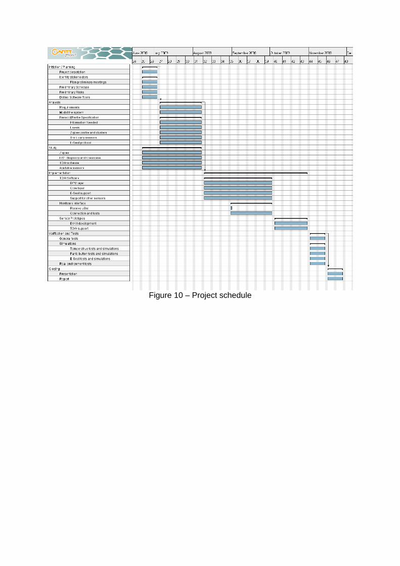
Figure 10 – Project schedule

4. Analysis and Design The analysis and design of the system to be developed was done during the process of development. An iterative approach was chosen because Rhapsody is a model driven development tool, which means that by creating the model it is possible to generate most of the source code. That changes the development approach drastically, since the focus changes from coding to modeling. In this phase, as the model would be done during the development, the most important artifact was the protocol specification. With that it was possible to have a better understanding to model the system.
4.1. Requirements Based on the meeting with Datachassi, discussion with stakeholders and other documents, the requisites were listed and prioritized as shown in Table 1.
No. Pty. Description
1 1 The TGW should be able to communicate with the Combiseal and DNet lamps through the uGW.
2 1 The uGW will use Zigbee to communicate with the DNet lamps and the Combiseal.
3 1 The communication between the TGW and the uGW is specified in a Protocol Description document. The objective of this protocol is to transport Zigbee Application layer messages using an RS232 link.
4 1 The uGW will be the Zigbee coordinator and will be responsible for the network management of the devices in the network.
5 1 The TGW has to be able to configure, turn on or off the CombiSeal door alarm and other alarms.
6 1 The Combiseal will monitor if the trailer door is open or closed and send this information to the TGW, which will send this information to the web portal.
7 1 The TGW should be able to use the web portal through a GPRS connection as a user interface.
8 1 The TGW will use the user interfaces to show sensor status, alarms and to configure the sensors.
9 2 The uGW should allow third party devices in the Zigbee network.
10 2 Messages from third party devices should be forwarded directly to the TGW.
11 3 For this first version, the integration with the DNet lamps will not be implemented, but the system has to support this addition later.
12 3 A secure authentication procedure between the uGW and TGW has to be supported for later implementation.
13 3 The system should be able to identify hardware and software versions as well as manufacturer and model identification to improve compatibility
14 4 The system should be able to confirm the identity of the Combiseal device
Table 1

This list was updated a few times during the project but in the end most of the requisites were implemented in the final version of the system. The most important changes in the requisite list are regarding the user interfaces. The first plan was to use both the TTU and the web portal as user interfaces, to be able to show information to the driver and at the same time have this information in the control center. After some considerations, the implementation of the TTU integration was removed from the scope. Another important modification was the way that the system would work with third party wireless sensors. A simplification of the procedures was done for this first version, but future improvements can be done to make the wireless network more secure.
4.2. System model After careful consideration of the TGW software architecture, of the Zigbee protocol stack and of the system functionalities, a model was drawn with basic layers and modules of the system. This model is shown in Figure 11.
Zigbee
(DPM)
USART
(BPS)
ZCL
(Core)
Application
(Business)TTU
Web Portal
uGW
E-Seal sensor
TGW
Figure 11 – System model overview
Some connections with other modules of the TGW software were not specified in this general model. Some of them are the persistent data management, watchdog, debug, etc. The USART module resides in the BPS layer and was already implemented. The Zigbee module uses it to access the serial port and communicate with the uGW. Only some minor changes were needed in this module. The Zigbee software module is in the DPM layer and is responsible for managing the communication with the uGW. The ZCL software module is in the Core layer and is responsible for managing the sensors. This module is also responsible for managing the persistent data of the sensors, for instance the door status of the E-Seal. The Application software module is in the Business layer and manages the communication with the portal and TTU. It was developed by other engineers at Volvo and in this first version only communicates with the web portal.
4.3. Protocol specification The main idea for the communication between the TGW and the uGW was to use a protocol that could transport Zigbee application messages on top of an RS232 connection. Some other additions had to be done to enable network management. The final specification is included in Appendix II and examples of the frames are included in Appendix IV.
4.3.1. Zigbee protocol The Zigbee stack is composed of four layers which have entities responsible for data transmission services and management services [25]. An overview of the stack can be seen in Figure 12 below.

Figure 12 – Outline of the Zigbee Stack Architecture
On top of the stack resides the manufacturer defined applications and the Zigbee Device Object (ZDO), which is responsible for most of the management functions. They use the features of the network through a set of services provided by the Application Support Sublayer (APS). Every sensor in a Zigbee network communicates using a subset of the Zigbee Cluster Library [26], defined in the form of an Application Profile. For example there is a standard application profile for Home Automation. Within this profile there is a thermostat cluster, used to provide functionality mostly for temperature devices like air conditioning and heating systems. One Zigbee device can support more than one application. This is achieved by having more than one Application Object running in different endpoints, supporting different clusters and possibly different application profiles. The supported clusters can also be either client or servers. All this information is stored in the device simple descriptor, which is shown in Appendix IV. To establish the communication of two devices, a procedure called binding is carried out by the network coordinator. For example a lighting switch has to connect to a light bulb to turn it on or off. The switch can have the client side of the On/Off cluster and the bulb can have the server side. Both devices report their simple descriptor to the coordinator, which in turn matches their clusters and send binding commands to each of them. After that the communication between the switch and the bulb is established.

4.3.2. uGW protocol In order to have all the functionality needed in the TGW for wireless sensors, the protocol to communicate with the uGW was specified in 5 layers:
1. Application layer 2. APS layer 3. Data layer 4. Link layer 5. Physical layer
The Application layer follows the ZCL specification for messages exchanged with Application Objects. For messages exchanged with the ZDO, the Zigbee Device Profile was used with some small changes. The APS layer is a subset of the APS sublayer of the standard Zigbee specification. The primitives included follow exactly the Zigbee specification, but only a few were implemented since there was no need for using all of them in this project. However, the protocol allows future implementation of other primitives if the need arises. The Data layer specifies which APS primitive it is transporting and also provides some fault tolerance mechanisms by implementing a simple checksum and acknowledgements. The Link layer manages the beginning and ending of frames. The Physical layer is the RS232 serial interface. For detailed information about the communication protocol see Appendix II and Appendix IV.
4.3.3. Sensors protocol The protocol for communicating with the sensors was based on the ZCL. A small set of clusters was chosen to make the application simple but at the same time give all the functionality needed for the project. The E-Seal protocol was defined by Datachassi, but later in the project it was decided to implement only a subset of the complete set of clusters. The panic button sensor and the temperature sensor protocols were defined during the work and they included only essential characteristics. More information about the sensors protocol can be seen in Appendix III.

5. Implementation
5.1. TGW software The TGW software is the most important deliverable of this project. Because of that most of the work was dedicated to develop the software modules. The architecture of the software followed the structure defined in the system model (see chapter 4.2).
5.1.1. DPM Layer The DPM layer includes all functionality to manage the communication with the uGW. It is composed of the 4 base layers of the uGW protocol (see chapter 4.3.2). All the classes implemented in this layer are contained within the ZigbeePkg package in the DPMPkg package of the TGW software. An overview of the protocol implementation is shown in Figure 13.
LinkLayer
LinkLayer()
init():void
readMsg(msg:unsign...
sendMsg(msg:unsig...
1
IComport
«Interface»
111
DataLayer
DataLayer()
receiveMsg():void
notifyIncoming():void11
ZigbeeEndpoint
ZigbeeEndpoint(subscr...
bind(profileId:unsigned ...
bind(clusterId:unsigne...
notifyInd(msg:APSDat...
notifyRes(result:bool):v...
sendMsg(device:IZigbe...
sendMsg(group:IZigbe...
APSLayer
sendDataReq(endpoint:unsigned ...
notifyResult(result:bool):void
notifyIncoming(primitive:PrimitiveI...
sendUpdReq(msg:APSUpdateRe...
1
1
1
*
endpoint
1
1
1
*
endpoint
ZDOApplication
ZDOApplication()
init():void
notifyUpdInd(msg:APSU...
notifyDataInd(msg:APS...
notifyRes(result:bool):void
sendDataReq(clusterId:u...
1
1
1
1
Figure 13 – DPM layer overview

5.1.1.1. Link Layer The LinkLayer class is responsible for managing the serial port communication and interpreting the Link layer of the uGW protocol. An overview of the protocol link layer can be seen in Figure 14.
DLE STX Payload DLE ETX
Figure 14 – Link layer frame format (in yellow) In order to read from the serial port, a polling scheme is used. Every 50ms the class checks if the serial port received something and if it matches the beginning of a frame, it starts reading until it reaches the end of the frame or a timeout. When a frame is read successfully, it is sent to the DataLink class. The LinkLayer statechart is shown in Figure 15.
idle
[openComport()][openComport()]
[else]
preStartevStartLink
[else]
evStartLink
reading
tm(50)[sizeBufferIn==0]
[readDLE()]
[else]
tm(50)[sizeBufferIn==0]
[readDLE()]
[else]
[else][else]
readingFrame
readFrame(); ...[readSTX()]/
finished=false;
readings=0;
[readSTX()]/
finished=false;
readings=0;
[finished][finished] [else] waiting
tm(50)
[else]
tm(50)
Figure 15 – LinkLayer statechart
5.1.1.2. Data Layer The DataLayer class is responsible for processing the Data layer frames of the uGW protocol. It identifies the Zigbee APS Sublayer primitive that is being transported and has some fault tolerance mechanisms using frame sequence numbers, checksum and acknowledgements. The frame format of the Data layer is shown in Figure 16 and Figure 17.
DLE STX Primitive Sequence Length Payload Checksum DLE ETX
Figure 16 – Data layer frame format (in blue)
DLE STX Ack or Nack Sequence Checksum DLE ETX
Figure 17 – Data layer ack/nack frame format (in blue)

Another important function of the DataLayer class is to manage re-transmission, in case a Nack is received or an Ack is not received within the time limit. The statechart for this class can be seen in Figure 18
idle
evReadData
reading
evReadData
evWriteData/
write();
writing
evWriteData/
write();
waitAck evReadDataevReadData
[else]
[waitingAck]
[else]
[waitingAck]
tm(5000)
[sendTimes < MAX_SEND]
[else]/
sendFailed();
tm(5000)
[sendTimes < MAX_SEND]
[else]/
sendFailed();
Figure 18 – DataLayer statechart
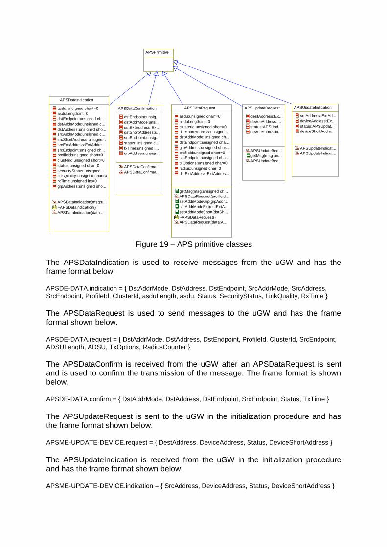
5.1.1.3. APS Layer and Primitives The APSLayer class implements the functionality of the Zigbee APS Sublayer. To process all the primitives used in the uGW protocol, each primitive has a corresponding class, shown in Figure 19, which is responsible for encoding and decoding the messages in the primitives. The objects of these classes are used for communication with the higher layer classes.
APSDataIndication
asdu:unsigned char*=0
asduLength:int=0
dstEndpoint:unsigned ch...
dstAddrMode:unsigned c...
dstAddress:unsigned sho...
srcAddrMode:unsigned c...
srcShortAddress:unsigne...
srcExtAddress:ExtAddre...
srcEndpoint:unsigned ch...
profileId:unsigned short=0
clusterId:unsigned short=0
status:unsigned char=0
securityStatus:unsigned ...
linkQuality:unsigned char=0
rxTime:unsigned int=0
grpAddress:unsigned sho...
APSDataIndication(msg:u...
~APSDataIndication()
APSDataIndication(data:...
APSPrimitive
APSDataRequest
asdu:unsigned char*=0
asduLength:int=0
clusterId:unsigned short=0
dstShortAddress:unsigne...
dstAddrMode:unsigned ch...
dstEndpoint:unsigned cha...
grpAddress:unsigned shor...
profileId:unsigned short=0
srcEndpoint:unsigned cha...
txOptions:unsigned char=0
radius:unsigned char=0
dstExtAddress:ExtAddres...
getMsg(msg:unsigned ch...
APSDataRequest(profileId...
setAddrModeGrp(grpAddr...
setAddrModeExt(dstExtA...
setAddrModeShort(dstSh...
~APSDataRequest()
APSDataRequest(data:A...
APSDataConfirmation
dstEndpoint:unsig...
dstAddrMode:unsi...
dstExtAddress:Ex...
dstShortAddress:u...
srcEndpoint:unsig...
status:unsigned c...
txTime:unsigned i...
grpAddress:unsign...
APSDataConfirma...
APSDataConfirma...
APSUpdateRequest
destAddress:Ex...
deviceAddress:...
status:APSUpd...
deviceShortAdd...
APSUpdateReq...
getMsg(msg:un...
APSUpdateReq...
APSUpdateIndication
srcAddress:ExtAd...
deviceAddress:Ex...
status:APSUpdat...
deviceShortAddre...
APSUpdateIndicat...
APSUpdateIndicat...
Figure 19 – APS primitive classes
The APSDataIndication is used to receive messages from the uGW and has the frame format below: APSDE-DATA.indication = { DstAddrMode, DstAddress, DstEndpoint, SrcAddrMode, SrcAddress, SrcEndpoint, ProfileId, ClusterId, asduLength, asdu, Status, SecurityStatus, LinkQuality, RxTime }
The APSDataRequest is used to send messages to the uGW and has the frame format shown below. APSDE-DATA.request = { DstAddrMode, DstAddress, DstEndpoint, ProfileId, ClusterId, SrcEndpoint, ADSULength, ADSU, TxOptions, RadiusCounter }
The APSDataConfirm is received from the uGW after an APSDataRequest is sent and is used to confirm the transmission of the message. The frame format is shown below. APSDE-DATA.confirm = { DstAddrMode, DstAddress, DstEndpoint, SrcEndpoint, Status, TxTime }
The APSUpdateRequest is sent to the uGW in the initialization procedure and has the frame format shown below. APSME-UPDATE-DEVICE.request = { DestAddress, DeviceAddress, Status, DeviceShortAddress }
The APSUpdateIndication is received from the uGW in the initialization procedure and has the frame format shown below. APSME-UPDATE-DEVICE.indication = { SrcAddress, DeviceAddress, Status, DeviceShortAddress }

For more information about the Zigbee APS Sublayer primitives see [25]. Because each primitive has a different frame format, dynamic length and is used for different purposes, it is important to identify which primitive is being received or sent and process it accordingly. After creating the appropriate object according to the primitive being received, the APSLayer dispatches the message to its recipient. Outgoing messages are sent to the DataLayer, but some need waiting for a confirmation. Incoming messages are sent to the destination endpoint application or to the ZDO. The statechart for the APSLayer is shown in Figure 20.
idle
evAPSDataInd/
processDataInd();
receivingInd
evAPSDataInd/
processDataInd();
tm(250)
evAPSUpdInd/
processUpdInd();
tm(250)
evAPSUpdInd/
processUpdInd();
sendingReq
tm(5000)/
processDataRes(false);
tm(5000)/
processDataRes(false);
waitingConf
tm(10000)/
processDataRes(false);
evAPSDataConf/
processDataRes(processDataConf());
tm(10000)/
processDataRes(false);
evAPSDataConf/
processDataRes(processDataConf());
evAPSDataReq
[else]/
processDataRes(false);
[processDataReq()]
evAPSDataReq
[else]/
processDataRes(false);
[processDataReq()]
evAPSResult
[params->result]
[else]/
processDataRes(false);
evAPSResult
[params->result]
[else]/
processDataRes(false);
sendingUpdevAPSResult/
processUpdRes(params->result);
tm(4000)/
processUpdRes(false);
evAPSResult/
processUpdRes(params->result);
tm(4000)/
processUpdRes(false);
evAPSUpdReq
[processUpdReq()]
[else]/
processUpdRes(false);
evAPSUpdReq
[processUpdReq()]
[else]/
processUpdRes(false);
Figure 20 – APSLayer statechart
As this communication channel is used by multiple endpoints and the ZDO, queues for incoming and outgoing messages are implemented. Fragments of code are shown below and demonstrate how the messages are processed:

void APSLayer::notifyIncoming(const PrimitiveID& primitive, unsigned char* msg, int size) {
APSDataIndication *dataInd;
APSUpdateIndication *updInd;
switch (primitive) {
case DATAindication:
dataInd = new APSDataIndication(msg, size);
queueDataInd.push(dataInd);
if (IS_IN(idle)) GEN(evAPSDataInd);
break;
case DATAconfirm:
if (IS_IN(waitingConf)) {
incDataConf = new APSDataConfirmation(msg, size);
GEN(evAPSDataConf);
}
break;
case UPDATEindication:
updInd = new APSUpdateIndication(msg, size);
queueUpdInd.push(updInd);
if (IS_IN(idle)) GEN(evAPSUpdInd);
break;
}
}
bool APSLayer::processDataConf() {
bool result = false;
dbgDebug(ID_ZIGBEE, "APS Layer: receiving DATA.conf");
if (queueDataReq.front()->getSrcEndpoint() == incDataConf->getSrcEndpoint()) {
if (incDataConf->getStatus() == APSPrimitive::APS_SUCCESS) {
result = true;
} else {
dbgDebug(ID_ZIGBEE, "APS Layer: invalid status in DATA.conf");
}
} else {
dbgDebug(ID_ZIGBEE, "APS Layer: invalid endpoint in DATA.conf");
}
delete incDataConf;
incDataConf = NULL;
return result;
}
void APSLayer::processDataInd() {
APSDataIndication *dataInd;
ZigbeeEndpoint* app;
dbgDebug(ID_ZIGBEE, "APS Layer: receiving DATA.indication");
dataInd = queueDataInd.front();
if (checkAddress(dataInd)) {
if (dataInd->getDstEndpoint() == 0) {
if(itsZDOApplication) itsZDOApplication->notifyDataInd(dataInd);
} else {
app = getItsZigbeeEndpoint(dataInd->getDstEndpoint());
if(app) app->notifyInd(dataInd);
else dbgDebug(ID_ZIGBEE, "APS Layer: invalid endpoint in DATA.indication");
}
} else {
dbgDebug(ID_ZIGBEE, "APS Layer: invalid address in DATA.indication");
}
delete queueDataInd.front();
queueDataInd.pop();
}

bool APSLayer::processDataReq() {
APSDataRequest *dataReq;
unsigned char* msgOut;
int size;
bool result = false;
dbgDebug(ID_ZIGBEE, "APS Layer: sending DATA.request");
dataReq = queueDataReq.front();
size = dataReq->getMsg(&msgOut);
result = itsDataLayer->sendMsg(DATArequest, msgOut, size);
if (msgOut) delete msgOut;
return result;
}
void APSLayer::processDataRes(bool result) {
ZigbeeEndpoint *app;
if (result)
dbgDebug(ID_ZIGBEE, "APS Layer: sending DATA.request OK");
else
dbgDebug(ID_ZIGBEE, "APS Layer: sending DATA.request failed");
if (queueDataReq.front()->getSrcEndpoint() == 0) {
if(itsZDOApplication) itsZDOApplication->notifyRes(result);
} else {
app = getItsZigbeeEndpoint(queueDataReq.front()->getSrcEndpoint());
if(app) app->notifyRes(result);
}
mutexDataReq.lock();
delete queueDataReq.front();
queueDataReq.pop();
mutexDataReq.unlock();
}
void APSLayer::sendDataReq(unsigned char endpoint, APSDataRequest* msg) {
APSDataRequest *data;
data = new APSDataRequest(msg);
mutexDataReq.lock();
queueDataReq.push(data);
mutexDataReq.unlock();
GEN(evAPSDataReq);
}
5.1.1.4. ZDO Application and Commands The partial ZDO implemented in the TGW is responsible for two management functions: initialization and binding. The initialization procedure is used to tell the uGW which endpoints are active in the TGW and what functionalities they support. To do that, the ZDO in the TGW support the endpoint request command and the simple descriptor request command. For more information about these commands see [25]. For a sequence diagram of the initialization procedure see Appendix II. Binding is the process that virtually connects the TGW to a wireless sensor. In the initialization the TGW tells the uGW what kind of sensor it supports, so whenever the uGW finds a matching sensor in the network, it tells the TGW using the binding commands. For this purpose, the standard end device bind command was slightly
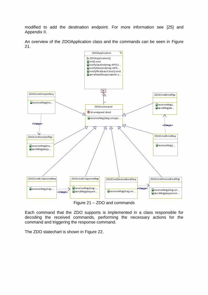
modified to add the destination endpoint. For more information see [25] and Appendix II. An overview of the ZDOApplication class and the commands can be seen in Figure 21.
ZDOApplication
ZDOApplication()
init():void
notifyUpdInd(msg:APSU...
notifyDa taInd(msg :APS...
notifyRes(resu lt:bool):void
sendDataReq(clusterId:u...
ZDOCommand
id:unsigned short
receiveMsg (msg:unsign...
1
*
id
1
*
id
ZDOCmdSimpleReq
receiveMsg(ms...
ZDOCmdSimpleRsp
receiveMsg(ms...
sendMsg(sequ...
«Usage»«Usage»
ZDOCmdEndpointsReq
receiveMsg(msg:...
ZDOCmdEndpointsRsp
receiveMsg(msg:...
sendMsg(sequen...«Usage»«Usage»
ZDOCmdBindReq
receiveMsg(...
ZDOCmdBindRsp
receiveMsg(...
sendMsg(se...
«Usage»«Usage»
ZDOCmdDeviceBindReq
receiveMsg(msg:un...
ZDOCmdDeviceBindRsp
receiveMsg (msg:un. ..
sendMsg(sequence:...
«Usage»«Usage»
Figure 21 – ZDO and commands
Each command that the ZDO supports is implemented in a class responsible for decoding the received commands, performing the necessary actions for the command and triggering the response command. The ZDO statechart is shown in Figure 22.

startup
STARTUP_DONE
idle
evZDODataReq/
processDataReq(params->value)
sending
SENDING_DONE
evZDODataReq/
processDataReq(params->value)
receiving
evZDODataInd/
processDataInd(params->value);
evZDODataInd/
processDataInd(params->value);
prestart
evZDOStartevZDOStart
startup
sendingUpReq
waitingUpRestm(3000)
tm(1000)/
sendUpReq();
waitingUpInd
tm(3000)evZDOUpRes
[params->result]
[else]
evZDOUpInd
[else]
STARTUP_DONE
[processUpdInd(params->value)]
tm(3000)
tm(1000)/
sendUpReq();
tm(3000)evZDOUpRes
[params->result]
[else]
evZDOUpInd
[else]
[processUpdInd(params->value)]
sending
writingReq
evZDODataRes
SENDING_DONE
tm(15000)
[params->result]
[else]
evZDODataRestm(15000)
[params->result]
[else]
Figure 22 – ZDOApplication statechart 5.1.1.5. Endpoints, Devices and Groups The Zigbee endpoints are implemented in the DPM layer by the ZigbeeEndpoint class. However, the application running on that endpoint is implemented in the Core layer, so an interface between these layers is needed. An overview of these classes and interfaces is shown in Figure 23.

ZDOApplication
ZDOApplication()
init():void
notifyUpdInd(msg:APSUpd...
notifyDataInd(msg:APSDa...
notifyRes(result:bool):void
sendDataReq(clusterId:un...
deviceShortAddress:unsig...
deviceExtAddress:ExtAdd...
* 1endpoint
ZigbeeEndpoint
endpoint:unsigned c...
ZigbeeEndpoint(subs...
getDeviceExt(addres...
getDeviceShort(addr...
bind(clusterId:unsign...
bind(profileId:unsigne...
notifyInd(msg:APSD...
notifyRes(result:bool...
sendMsg(device:IZig...
sendMsg(group:IZigb...
* 1endpoint
CbZigbeeEndpoint
«Interface»
notifyIncoming(devic...
getSimpleDescriptor...
notifyResponse(resu...
notifyNewDevice(dev...
notifyNewGroup(gro...
11
IZigbeeEndpoint
«Interface»
sendMsg(device:IZi...
sendMsg(group:IZig...
* 1* 1
ZigbeeDevice
dstEndpoint:unsi...
dstExtAddress:E...
dstShortAddress:...
ZigbeeDevice(end...
getEndpoint():uns...
getAddress():Ext...
getShortAddress(...
setShortAddress(...
*
1dstGrpAddress
ZigbeeGroup
dstGrpAddress:u...
ZigbeeGroup(addr...
getAddress():unsi...
*
1dstGrpAddress
IZigbeeDevice
«Interface»
getAddress():Ext...
getEndpoint():un...
getShortAddress...
IZigbeeGroup
«Interface»
getAddress():un...
Figure 23 – Endpoint classes
The interface for the Application Object in the Core layer is composed by two interfaces: IZigbeeEndpoint and CbZigbeeEndpoint. The Application Object should implement the CbZigbeeEndpoint interface to be able to receive the responses and notifications from the ZigbeeEndpoint, which implements the public interface IZigbeeEndpoint. The same endpoint can be virtually connected to more than one sensor. For instance, multiple E-Seal sensors can be monitoring the doors of two or more trailers in the truck, but these E-Seal sensors will be bound to the same endpoint in the TGW. The sensors are mapped in the class ZigbeeDevice in the DPM layer, which provides the communication functions to the Core Layer through the interface IZigbeeDevice. Another feature of the Zigbee networks is grouping. It is possible to have a group of similar devices mapped to one network address. However, this is only partially implemented in the TGW software. Every time a device that matches one of the endpoints is found in the network, the uGW notifies the ZDO in the TGW, which in turn calls the bind method of the endpoint. This method is shown below.

bool ZigbeeEndpoint::bind(unsigned short profileId, unsigned short shortAddress,
ExtAddressType extAddress, unsigned char endpoint) {
SimpleDescriptor* simpleDescriptor= itsCbZigbeeEndpoint->getSimpleDescriptor();
ZigbeeDevice* device;
// Check if the profile matches
if (simpleDescriptor->getProfileId() != profileId) {
dbgDebug(ID_ZIGBEE, "Endpoint: profile id doesn't match in binding");
return false;
}
device = getDeviceExt(extAddress, endpoint);
if (device == NULL) {
device = new ZigbeeDevice(endpoint, extAddress, shortAddress);
addItsZigbeeDevice(device);
} else {
dbgDebug(ID_ZIGBEE, "Endpoint: device already exists in binding");
device->setShortAddress(shortAddress);
}
itsCbZigbeeEndpoint->notifyNewDevice(device);
return true;
}
What the bind method does is checking if a device with the same MAC address is already registered. If it does, it updates the network address of this device, but if it does not exist, it creates a new device. After that it notifies the Application Object running in the core layer that a device was found or updated. 5.1.1.6. ZCL Frame The ZCL Frame is an important class in the communication between the DPM and Core layer modules. This class implements encoding and decoding of the ZCL frame. Objects of this class are passed between the interface classes of ZigbeePkg and WirelessSensorsPkg. The ZCL frame format is shown below. ZCL Frame = { FrameControl, ManufacturerCode, Transaction, CommandId, Payload } FrameControl = { FrameType, ManufacturerSpecific, Direction, DisDefaultRes }
The ZCLFrame class can be seen in Figure 24.

ZCLFrame
frameType:unsigned char=0
manufacturerSpecific:bool=0
direction:unsigned char=0
disableResponse:bool=0
manufacturerCode:unsigned short=0
transaction:unsigned char=0
commandId:unsigned char=0
payload:unsigned char*=0
payloadLength:unsigned char=0
ZCLFrame(msg:unsigned char*,size:int)
ZCLFrame(commandId:unsigned char,payload:un...
ZCLFrame(frame:ZCLFrame*)
getMsg(msg:unsigned char**):int
~ZCLFrame()
Figure 24 – ZCLFrame class
5.1.1.7. Module Interface In the previous sections a part of the interface with the Core layer was shown. However, according to the TGW software architecture, the main interface between modules should be a Singleton class. This class has only one instance in the system and is managed by the SystemModeManager in the System layer. As shown in Figure 25, the ZigbeeMng class is responsible for instantiating all the objects for this module. It also provides a connection with the IComport interface. The singleton ZigbeeMng class is an active class, which means that it runs in its own thread. By instantiating all the other objects properly, it is possible to make them run in the same thread as ZigbeeMng, making the whole module run in a single thread. Furthermore, this thread has to register itself to the watchdog and ping it regularly to show that it is executing properly.

ZigbeeMng
«SingletonImplementation»
ZigbeeMng()
getId():ModuleId
getName():const char*
deActivateModuleInit...
addEndpoint(endpoin...
IComport
«Interface»
11
IModule
«Interface»IZigbeeMng
«SingletonInterface»
init():void
addEndpoint(end...
1
ZigbeeFactory
itsZDOApplication:ZDOApplication1
itsAPSLayer:APSLayer1
itsLinkLayer:LinkLayer1
itsDataLayer:DataLayer1
1
Figure 25 – Module interface
The two methods of the interface provide all the functionality needed for the startup of the system. After that, the ZigbeeEndpoint objects and the ZDO take care of the communication themselves. The init method attaches the LinkLayer object to the Comport object and starts the statecharts of the other classes. The addEndpoint method creates the ZigbeeEndpoint object and attaches it to the ZDO and to the APSLayer objects. Subsequently all the data transmission will be done directly to this object and the management will be done by the ZDO. 5.1.1.8. Debug and Serial Port The debug unit and the serial port of the TGW had to be modified to connect the external serial port to the uGW. At the same time it was necessary to receive the debug messages. The first part of this task was to be able to receive debug messages. That was not difficult, since the messages could be enabled in the USB port. After that the serial port was connected to the ZigbeePkg module by adding an extra port to the ComportHandler.
For more information about the debug and serial port of the TGW see Appendix I. 5.1.1.9. Tests
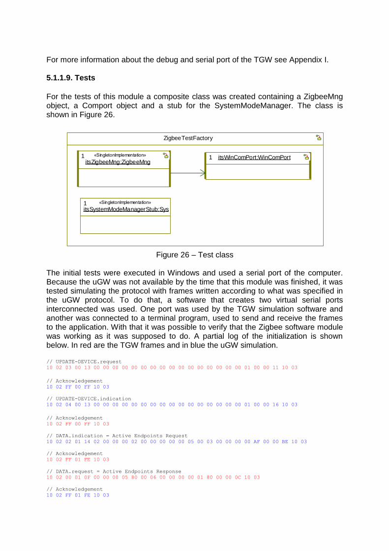
For the tests of this module a composite class was created containing a ZigbeeMng object, a Comport object and a stub for the SystemModeManager. The class is shown in Figure 26.
ZigbeeTestFactory
itsWinComPort:WinComPort1itsZigbeeMng:ZigbeeMng
1 «SingletonImplementation»
itsSystemModeManagerStub:SystemModeManagerStub1 «SingletonImplementation»
Figure 26 – Test class
The initial tests were executed in Windows and used a serial port of the computer. Because the uGW was not available by the time that this module was finished, it was tested simulating the protocol with frames written according to what was specified in the uGW protocol. To do that, a software that creates two virtual serial ports interconnected was used. One port was used by the TGW simulation software and another was connected to a terminal program, used to send and receive the frames to the application. With that it was possible to verify that the Zigbee software module was working as it was supposed to do. A partial log of the initialization is shown below. In red are the TGW frames and in blue the uGW simulation. // UPDATE-DEVICE.request
10 02 03 00 13 00 00 00 00 00 00 00 00 00 00 00 00 00 00 00 00 01 00 00 11 10 03
// Acknowledgement
10 02 FF 00 FF 10 03
// UPDATE-DEVICE.indication
10 02 04 00 13 00 00 00 00 00 00 00 00 00 00 00 00 00 00 00 00 01 00 00 16 10 03
// Acknowledgement
10 02 FF 00 FF 10 03
// DATA.indication = Active Endpoints Request
10 02 02 01 14 02 00 00 00 02 00 00 00 00 00 05 00 03 00 00 00 00 AF 00 00 BE 10 03
// Acknowledgement
10 02 FF 01 FE 10 03
// DATA.request = Active Endpoints Response
10 02 00 01 0F 00 00 00 05 80 00 06 00 00 00 00 01 80 00 00 0C 10 03
// Acknowledgement
10 02 FF 01 FE 10 03

// DATA.confirm
10 02 01 02 07 02 00 00 00 00 00 00 06 10 03
// Acknowledgement
10 02 FF 02 FD 10 03
// DATA.indication = Simple Descriptor Request
10 02 02 03 15 02 00 00 00 02 00 00 00 00 00 04 00 04 00 00 00 80 00 AF 00 00 3B 10 03
// Acknowledgement
10 02 FF 03 FC 10 03
// DATA.request = Simple Descriptor Response
10 02 00 02 1C 00 00 00 04 80 00 13 00 00 00 00 0E 80 01 00 01 00 10 10 00 03 00 00 06 00 00
05 00 00 17 10 03
// Acknowledgement
10 02 FF 02 FD 10 03
// DATA.confirm
10 02 01 04 07 02 00 00 00 00 00 00 00 10 03
// Acknowledgement
10 02 FF 04 FB 10 03
5.1.2. Core Layer The Core layer includes all functionality to manage the communication with the sensors. It is composed of the application layer of the uGW protocol (see chapter 4.3.2). All the classes implemented in this layer are contained within the WirelessSensorsPkg package in the CorePkg package of the TGW software. 5.1.2.1. Zigbee Cluster Library The ZCL implementation is one of the most important parts of the WirelessSensors module. It provides all the classes needed to build Application Objects. These classes implement clusters, attributes and commands. The Zigbee clusters are a set of attributes and commands specific for certain functionality. There are a number of standard commands that can be used for any kind of cluster and a number of specific commands used only for a particular cluster. For this project, four cluster classes were implemented, a generic cluster, an OnOff cluster, a Basic cluster and an IASZone cluster with their respective commands. These clusters can be seen in Figure 27.

ZigbeeCluster
id:unsigned short
type:clusterType=CLUSTER_U...
ZigbeeCluster(id:unsigned short)
notifyIncoming(device:Wireless...
ZigbeeOnOffCluster
ZigbeeOnOffClu...
notifyIncoming(...
ZigbeeGeneralCluster
ZigbeeGeneralClu...
notifyIncoming(dev...
ZigbeeIASZoneCluster
ZigbeeIASZoneClu...
notifyIncoming(devi...
Figure 27 – Cluster classes
For the attributes, only a generic class ZigbeeAttrib was implemented. For the commands, each one was implemented in a different class that encodes and decodes the frames for that specific command. Some commands have payloads with multiple attributes, as for instance the read response. In this case, another class links this command to its attributes, as shown in Figure 28.
ZCLCmdReadRes
ZCLCmdReadRes(clu...
getMsg(msg:unsigned...
setMsg(msg:unsigned...
addError(attribute:unsi...
addAttribute(attribute:...
getTypeId(pos:unsigne...
getAttribId(pos:unsign...
getAttribute(pos:unsig...
getValue(pos:unsigne...
getStatus(pos:unsigne...
quantAttrib():unsigned...
ZigbeeAttrib1
ZCLCmdReadResField
status:ZCLStatus
attribute:unsigned short
value:unsigned char*=...
valueLength:unsigned ...
typeId:TypeId
1**
Figure 28 – Read response command classes
The Read Attribute Response command frame format is described below. Read Attributes Response = { ReadRecord1, ReadRecord2, …, ReadRecordN } ReadRecord = { AttributeId, Status, DataType, Data}
5.1.2.2. Applications The Zigbee Application Objects are implemented in the TGW software in the ZigbeeApplication class and its relationships. Each application has a unique SimpleDescriptor that describes the features of that specific application. This set of features is composed by clusters and attributes.

An overview of the classes can be seen in Figure 29.
SimpleDescriptor
endpoint:unsigned char=0
profileId:unsigned short=0
deviceId:unsigned short=0
deviceVer:unsigned cha...
inClusterCount:unsigne...
outClusterCount:unsign...
inClusterList:unsigned ...
outClusterList:unsigned...
SimpleDescriptor(endpo...
getString(msg:unsigned...
addInCluster(cluster:un...
addOutCluster(cluster:u...
clusterMatches(clusterI...
ZigbeeCluster
id:unsigned short
type:clusterType=CLUS...
ZigbeeCluster(id:unsign...
notifyIncoming(device:W...
1 *id
1 *id
ZigbeeAttrib
id:unsigned short=0
typeId:TypeId=Zigb...
ZigbeeAttrib(id:unsi...
ZigbeeApplication
ZigbeeApplication(endp:unsigned char)
getSimpleDescriptor():SimpleDescrip...
notifyResponse(result:bool):void
notifyIncoming(device:IZigbeeDevice*...
notifyNewGroup(group:IZigbeeGroup*...
notifyNewDevice(device:IZigbeeDevic...
setEndpoint(endpoint:IZigbeeEndpoi...
deviceReady(device:IWirelessSensor...
sendMsg(device:IZigbeeDevice*,clust...
1
1 *id
1
1 *id
CbZigbeeEndpoint
«Interface»
1
IZigbeeEndpoint
«Interface»
1
WirelessDevice
online:bool=false
authorized:bool=false
unauthorized:bool=false
WirelessDevice(device:I...
notifyIncoming(comman...
authorize():void
unauthorize():void
isAuthorized():bool
sendMsg(command:ZCL...
sendDefaultRes(cluster:...
1
*
1
*IZigbeeDevice
«Interface»
11
Figure 29 – Application and ZCL classes
When a command is received from the associated endpoint, it is processed by the ZigbeeApplication class if it is a general command. If it is a cluster specific command, it is sent to the cluster that supports that command. If it is an unknown command, the Default Response is sent with a failure status. As each application can send and receive commands from multiple sensors, incoming and outgoing queues are used. The statechart for the ZigbeeApplication can be seen in Figure 30.
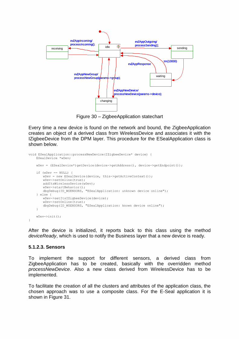
idle
evZAppOutgoing/
processSending();sending
evZAppOutgoing/
processSending();
waiting
tm(10000)evZAppResponse
tm(10000)evZAppResponse
receiving
evZAppIncoming/
processIncoming();
evZAppIncoming/
processIncoming();
changing
evZAppNewDevice/
processNewDevice(params->device);
evZAppNewGroup/
processNewGroup(params->group);
evZAppNewDevice/
processNewDevice(params->device);
evZAppNewGroup/
processNewGroup(params->group);
Figure 30 – ZigbeeApplication statechart
Every time a new device is found on the network and bound, the ZigbeeApplication creates an object of a derived class from WirelessDevice and associates it with the IZigbeeDevice from the DPM layer. This procedure for the ESealApplication class is shown below. void ESealApplication::processNewDevice(IZigbeeDevice* device) {
ESealDevice *wDev;
wDev = (ESealDevice*)getDevice(device->getAddress(), device->getEndpoint());
if (wDev == NULL) {
wDev = new ESealDevice(device, this->getActiveContext());
wDev->setOnline(true);
addItsWirelessDevice(wDev);
wDev->startBehavior();
dbgDebug(ID_WSENSORS, "ESealApplication: unknown device online");
} else {
wDev->setItsIZigbeeDevice(device);
wDev->setOnline(true);
dbgDebug(ID_WSENSORS, "ESealApplication: known device online");
}
wDev->init();
}
After the device is initialized, it reports back to this class using the method deviceReady, which is used to notify the Business layer that a new device is ready. 5.1.2.3. Sensors To implement the support for different sensors, a derived class from ZigbeeApplication has to be created, basically with the overridden method processNewDevice. Also a new class derived from WirelessDevice has to be implemented. To facilitate the creation of all the clusters and attributes of the application class, the chosen approach was to use a composite class. For the E-Seal application it is shown in Figure 31.
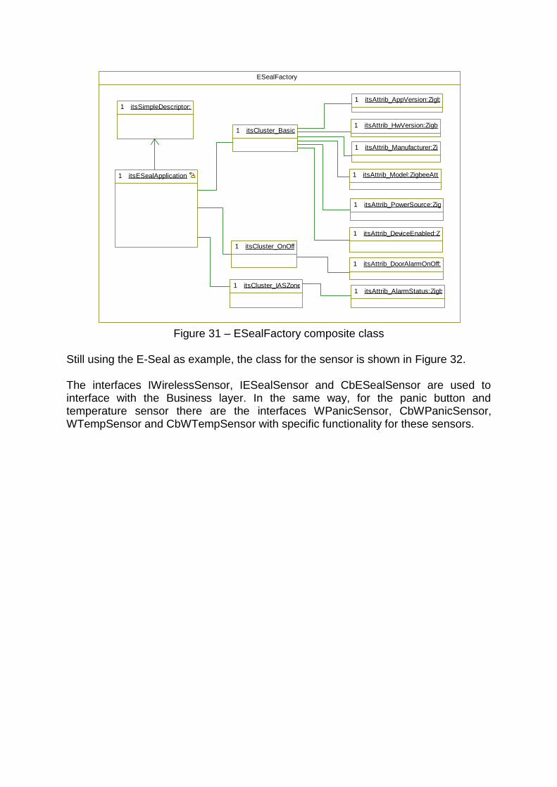
ESealFactory
itsAttrib_Model:ZigbeeAttrib1
itsAttrib_PowerSource:ZigbeeAttrib1
itsAttrib_DeviceEnabled:ZigbeeAttrib1
itsAttrib_DoorAlarmOnOff:ZigbeeAttrib1
itsAttrib_AlarmStatus:ZigbeeAttrib1
itsSimpleDescriptor:SimpleDescriptor1
itsESealApplication:ESealApplication1
itsCluster_IASZone:ZigbeeIASZoneCluster1
itsCluster_Basic:ZigbeeGeneralCluster1
itsCluster_OnOff:ZigbeeOnOffCluster1
itsAttrib_Manufacturer:ZigbeeAttrib1
itsAttrib_HwVersion:ZigbeeAttrib1
itsAttrib_AppVersion:ZigbeeAttrib1
Figure 31 – ESealFactory composite class
Still using the E-Seal as example, the class for the sensor is shown in Figure 32. The interfaces IWirelessSensor, IESealSensor and CbESealSensor are used to interface with the Business layer. In the same way, for the panic button and temperature sensor there are the interfaces WPanicSensor, CbWPanicSensor, WTempSensor and CbWTempSensor with specific functionality for these sensors.
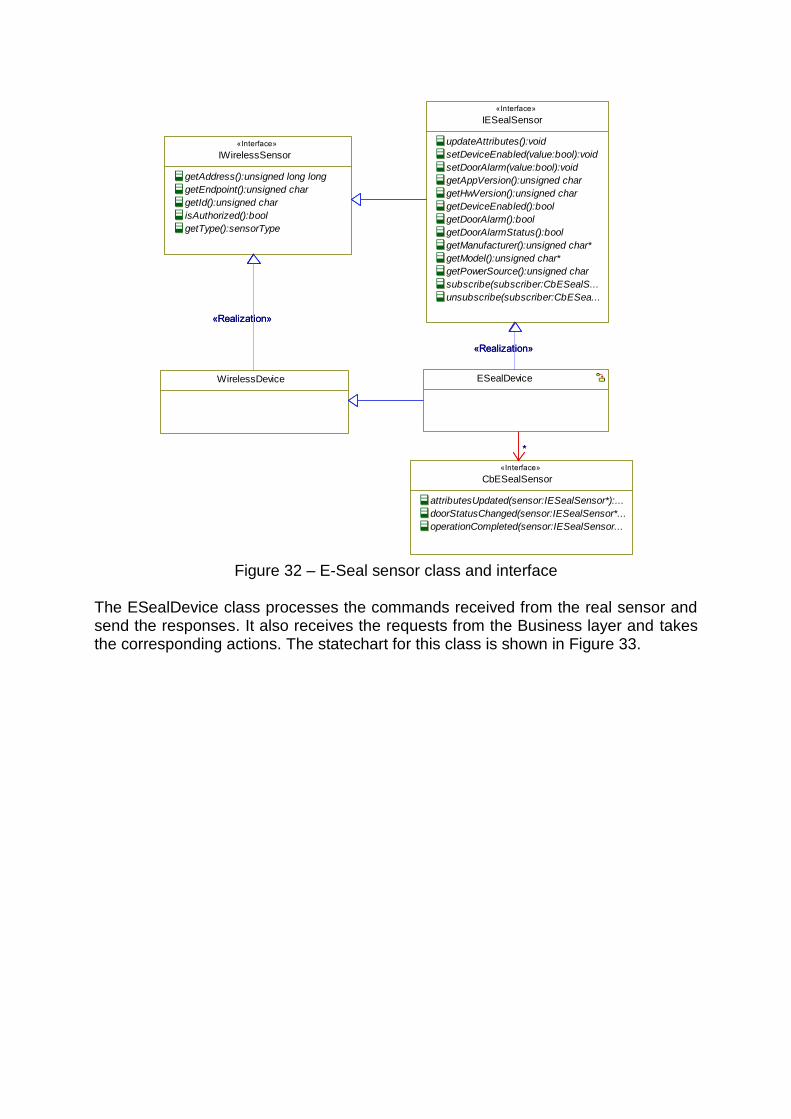
WirelessDevice
IWirelessSensor
«Interface»
getAddress():unsigned long long
getEndpoint():unsigned char
getId():unsigned char
isAuthorized():bool
getType():sensorType
«Realization»«Realization»
ESealDevice
«Realization»
IESealSensor
«Interface»
updateAttributes():void
setDeviceEnabled(value:bool):void
setDoorAlarm(value:bool):void
getAppVersion():unsigned char
getHwVersion():unsigned char
getDeviceEnabled():bool
getDoorAlarm():bool
getDoorAlarmStatus():bool
getManufacturer():unsigned char*
getModel():unsigned char*
getPowerSource():unsigned char
subscribe(subscriber:CbESealS...
unsubscribe(subscriber:CbESea...
«Realization»
*
CbESealSensor
«Interface»
attributesUpdated(sensor:IESealSensor*):...
doorStatusChanged(sensor:IESealSensor*...
operationCompleted(sensor:IESealSensor...
*
Figure 32 – E-Seal sensor class and interface
The ESealDevice class processes the commands received from the real sensor and send the responses. It also receives the requests from the Business layer and takes the corresponding actions. The statechart for this class is shown in Figure 33.

idleupdatingBasic1evESealDevUpdBasic1evESealDevUpdBasic1
updatingOnOff
updatingIASZoneevESealDevUpdIASZone
evESealDevUpdFinished/
notifyUpdate(true);
tm(20000)/
notifyUpdate(false);
tm(20000)
evESealDevUpdIASZone
evESealDevUpdFinished/
notifyUpdate(true);
tm(20000)/
notifyUpdate(false);
tm(20000)
evESealDevEnable/
enableDevice(params->value);
enablingDevice
tm(20000)/
notifyCompleted(false);
evESealDevCompleted/
notifyCompleted(params->result);
evESealDevEnable/
enableDevice(params->value);
tm(20000)/
notifyCompleted(false);
evESealDevCompleted/
notifyCompleted(params->result);
evESealDevAlarm/
enableAlarm(params->value);
enablingAlarm
tm(20000)/
notifyCompleted(false);
evESealDevCompleted/
notifyCompleted(params->result);
evESealDevAlarm/
enableAlarm(params->value);
tm(20000)/
notifyCompleted(false);
evESealDevCompleted/
notifyCompleted(params->result);
updatingBasic2
evESealDevUpdOnOff
tm(20000)
tm(20000)
evESealDevUpdBasic2
evESealDevUpdOnOff
tm(20000)
tm(20000)
evESealDevUpdBasic2
Figure 33 – ESealDevice statechart
Taking as an example the processing of a Read Attributes Response command, part of the code is shown below. Observe that depending on the state of the object, it can trigger other events using the Rhapsody macro GEN. void ESealDevice::cmdReadRes(ZCLCmdReadRes* command) {
unsigned char *value;
unsigned char valueLength;
dbgDebug(ID_WSENSORS, "ESealDevice: read response");
for (int i=0; i<command->quantAttrib(); i++) {
if (command->getStatus(i)==ZCLFrame::ZCL_SUCCESS) {
valueLength = command->getValue(i, &value);
storeAttrib(command->getClusterId(), command->getAttribId(i),
command->getTypeId(i), value, valueLength);
delete value;
}
}
if (IS_IN(updatingBasic1) && (command->getClusterId()==0x0000))
GEN(evESealDevUpdBasic2);
else if (IS_IN(updatingBasic2) && (command->getClusterId()==0x0000))
GEN(evESealDevUpdOnOff);
else if (IS_IN(updatingOnOff) && (command->getClusterId()==0x0006))
GEN(evESealDevUpdIASZone);
else if (IS_IN(updatingIASZone) && (command->getClusterId()==0x0500))
GEN(evESealDevUpdFinished);
}

void ESealDevice::storeAttrib(unsigned short clusterId, unsigned short attribId, const
ZigbeeAttrib::TypeId& typeId, unsigned char* value, unsigned char valueLength) {
unsigned short alarm;
switch (clusterId) {
//Basic Cluster
case 0x0000:
switch (attribId) {
case 0x0001:
if (typeId==ZigbeeAttrib::ZCL_TYPE_UNSINT8) {
appVersion = value[0];
}
break;
case 0x0003:
if (typeId==ZigbeeAttrib::ZCL_TYPE_UNSINT8) {
hwVersion = value[0];
}
break;
case 0x0004:
if (typeId==ZigbeeAttrib::ZCL_TYPE_STRING_CHAR) {
if (manufacturer) delete manufacturer;
manufacturer = new unsigned char[valueLength];
memcpy(manufacturer,value,valueLength);
}
break;
case 0x0005:
if (typeId==ZigbeeAttrib::ZCL_TYPE_STRING_CHAR) {
if (model) delete model;
model = new unsigned char[valueLength];
memcpy(model,value,valueLength);
}
break;
case 0x0007:
if (typeId==ZigbeeAttrib::ZCL_TYPE_ENUM8) {
powerSource = value[0];
}
break;
case 0x0012:
if (typeId==ZigbeeAttrib::ZCL_TYPE_LOGICAL) {
if (value[0]==0) deviceEnabled = false;
else deviceEnabled = true;
}
break;
}
break;
//OnOff Cluster
case 0x0006:
if (attribId==0x0000 && typeId==ZigbeeAttrib::ZCL_TYPE_LOGICAL) {
if (value[0]==0) doorAlarmOn = false;
else doorAlarmOn = true;
}
break;
//IASZone Cluster
case 0x0500:
if (attribId==0x0002 && typeId==ZigbeeAttrib::ZCL_TYPE_BITMAP16) {
alarm = doorAlarm;
doorAlarm = value[1];
doorAlarm = doorAlarm << 8;
doorAlarm = doorAlarm | value[0];
if (IS_IN(idle) && ((alarm&0x0001)!=(doorAlarm&0x0001)))
notifyAlarm();
}
break;
}
}
When the sensor is first created or become online, the object is in the initialization state, which means that it will perform a series of commands with the remote sensor to update the attributes, enable the device, set alarms etc.

As an example, the updateAttributes method can be called from the Business layer to read all the attributes in the remote sensor and update the attribute values in the TGW memory. When this method is called, it triggers the event evESealDevUpdBasic1, which will make the object change to state updateBasic1. When the object enters this state, it calls the private method updateBasicCluster1, which sends a read attributes command to the sensor. After the response for this command is received, the values for the attributes are stored and it triggers the event evESealDevUpdBasic2, which changes the object state to updateBasic2. This process goes on until all the attributes are read. If a response for one command does not arrive, the states have timeouts and change to the following state. The method updateBasicCluster1 is shown below. void ESealDevice::updateBasicCluster1() {
ZCLCmdRead *cmd;
ZigbeeCluster *cluster;
dbgDebug(ID_WSENSORS, "ESealDevice: updating Basic Cluster");
cluster = itsZigbeeApplication->getItsZigbeeCluster(0x0000);
cmd = new ZCLCmdRead(cluster);
cmd->addAttribute(cluster->getItsZigbeeAttrib(0x0001));
cmd->addAttribute(cluster->getItsZigbeeAttrib(0x0003));
cmd->addAttribute(cluster->getItsZigbeeAttrib(0x0004));
sendMsg(cmd);
delete cmd;
}
5.1.2.4. Module Interface In the same way as the interface of the ZigbeePkg, the interface of this module is composed of an active Singleton class, shown in Figure 34. It also has its own thread and is attached to the watchdog.
IModule
«Interface»
IWirelessSensorsMng
«SingletonInterface»
authorizeSensor(sensor:IWirel...
unauthorizeSensor(sensor:IWi...
getSensors(sensors:std::list<I...
subscribe(subscriber:CbWirel...
unsubscribe(subscriber:CbWi...
getAuthorizedSensors(sensor...
getUnauthorizedSensors(sens...
WirelessSensorsMng
«SingletonImplementation»
1 *
ZigbeeApplication
1 *
*
CbWirelessSensorsMng
«Interface»
onlineSensor(sensor:IWirelessS...
*
Figure 34 – WirelessSensorsMng class and interfaces

Regarding the interface with the Business layer, the WirelessSensorsMng class implements a set of methods defined in the interface IWirelessSensorsMng, and uses the callback interface CbWirelessSensorsMng to notify when a sensor is online. The methods getSensors, getAuthorizedSensors and getUnauthorizedSensors return a list of all the sensors, of the authorized sensors and of the unauthorized sensors respectively. A sensor is authorized when it is recognized by the application as being a valid sensor. This is done using the method authorizeSensor. On the other hand, a sensor is unauthorized using the method unauthorizeSensor when it is recognized as being an unknown or invalid sensor. The methods subscribe and unsubscribe are used to register and unregister a listener object that implements the interface CbWirelessSensorsMng. 5.1.2.5. Persistent data In order to preserve the information of which sensors were authorized and which ones were unauthorized, the system needed some kind of persistent data. To do that, the idea was to store the list of all sensors in the persistent memory of the TGW. The persistence of data in the TGW is a particular and interesting case. The system implements support for Serializable classes, which means that the objects of these classes encode and decode themselves into stream buffers. Furthermore, there is a module called SettingsManager, which is responsible for storing and retrieving these buffers from the persistent memory. The approach then was to make the ZigbeeApplication class derive from Serializable and implement the encode and decode methods. However, the WirelessSensorsMng object was the responsible for saving this information whenever a change occurred and reading the list of sensors at startup. 5.1.2.6. Tests To test the WirelessSensorsPkg a similar approach to the tests of the ZigbeePkg was taken. A class ZigbeeTestFactory was created in this module too, but this class has some additional functionality. It implements the callback interfaces CbWirelessSensorsMng, CbESealSensor, CbWPanicSensor and CbWTempSensor. This was done to test the system in Windows and be able to receive the messages from the sensors. The next test was to run the software in the TGW hardware. It was necessary to add the ZigbeePkg and WirelessSensorsPkg to the rest of the TGW software and put the ZigbeeMng and WirelessSensorsMng in the creation list at startup. After that the software was compiled and downloaded to the TGW hardware.
5.2. Hardware In the beginning of this project it was expected to be received a uGW and an E-Seal devices. The estimated dates for delivering these equipments were set in the first week. However, none of them was received in the prototype form. The E-Seal project

was delayed and was removed from the scope of this project. The uGW was received in the form of an early development prototype.
5.2.1. uGW prototype The uGW prototype received was composed of two development kits connected with soldered wires. One kit has the microcontroller and the other has the RF interface. The first kit is the Atmel EVK1101[27] with an AVR32 AT32UC3B microcontroller as shown in Figure 35. The second kit is the RCB231ED [28] with and AT86RF231 RF chip, similar to the one shown in Figure 36, designed by Dresden Elektronik.
Figure 35 – Atmel EVK1101
Figure 36 – RCB231ED
The combination of the two kits resulting in the uGW prototype is shown in Figure 37.

Figure 37 – uGW Prototype
With this prototype it was possible to complete the development of the system and perform all the tests. However, with this configuration it was impossible to do the demonstration in a moving truck, because the soldered wires would break apart.
5.3. Sensor prototypes Mostly because the E-Seal was excluded from the scope, it was decided to develop prototypes for sensors. The most important was a simulator for the E-Seal. It was also decided to develop a movable panic button and a temperature sensor. The first step of the development of the sensors was to change the application that run in the ATmega3290P microcontroller to read the temperature from the thermistor and to monitor the joystick to identify if the button was pressed. It was also necessary to send this information to the ATmega1284P microcontroller for processing and sending to the Zigbee network. This first task was made easy because all these functions are present in the original Raven firmware [29], downloadable at the Atmel website. Subsequently these functions were merged in the BitCloud firmware. The second step of the development was to read the information sent from the ATmega3290P microcontroller and take the necessary actions. This was also facilitated by using some code present in the original Raven firmware and the WSNDemo application example of the BitCloud SDK. However, the final code was not very good in structure because the BitCloud encapsulates the serial port communication in the LCD support drivers. A workaround with a callback function
was developed, since it was not necessary to have production level code for the sensors. Part of the code is shown below. /***********************************************************************************
Process the message received from the 3290P
***********************************************************************************/
static void checkMsg(void)
{
// If it is a key command and the key is ENTER
if (buffer[1]==0x01 && buffer[2]==0x10) {
if (alarmValue) {
visualizeNormal();
alarmValue = 0;
} else {
visualizeAlarm();
alarmValue = 1;
}
if (WAITING_DEVICE_STATE == appDeviceState) {
sendDeviceStatus();
appDeviceState = SENDING_DEVICE_STATE;
appPostSubTaskTask();
}
}
rxSize = 0;
}
/***********************************************************************************
Reads the incoming message from the 3290P processor
***********************************************************************************/
void usartRxCallback(uint8_t readBytesLen)
{
uint8_t sizeRead = 0;
if (rxSize + readBytesLen < 10) {
sizeRead = BSP_ReadUart(buffer+rxSize, readBytesLen);
rxSize += sizeRead;
if (buffer[rxSize-1]==SIPC_EOF) checkMsg();
} else {
rxSize = 0;
}
}
An interesting feature of the BitCloud stack is that it has a task manager implemented which is responsible for scheduling the protocol tasks and user tasks. Most of the development for this stack has to be done using callback functions. For instance to process the data received from the RF interface, it is necessary to register a callback function in the stack. This function is supposed to have a short execution time, so if more processing is needed, it is possible to post a task to the scheduler.
5.3.1. Door sensor simulator The door sensor developed simulates the E-Seal by changing the door status when the button is pressed. Every time the joystick is pressed, the software checks if the status of the door is open or closed, inverts it and sends the new status to the TGW. Apart from that, it answers all the commands from the TGW accordingly. This helped to test and debug all the initialization procedure and the alarm notification in the TGW software. A communication log of the TGW and the E-Seal simulator can be seen in Appendix V.

5.3.2. Movable panic button The idea of the movable panic button is that it can be installed anywhere in the truck or even taken with the driver when he/she leaves the truck. An additional function is message reception. The device is able to receive text messages from the TGW and show them in the LCD display. For messages longer than the display, it scrolls to the sides. With this feature it is possible to send a message from the web portal directly to the driver.
5.3.3. Temperature sensor The temperature sensor is based in a Negative Temperature Coefficient thermistor attached to the Analog-Digital converter in the Raven board. This implementation has some issues. The first is that the thermistor is located very near the power supply of the board. As a result the power supply might increase the temperature read. The second issue is because one of the AD lines used to read the value of the thermistor is also connected to the JTAG interface. Consequently to be able to read the value of the thermistor it is necessary to disable the JTAG and the debugging features. As this sensor is supposed to be installed in the trailer, for demonstration purposes it was also added a Trailer ID in the same device. The idea is to be able to identify which trailer is connected to the truck.
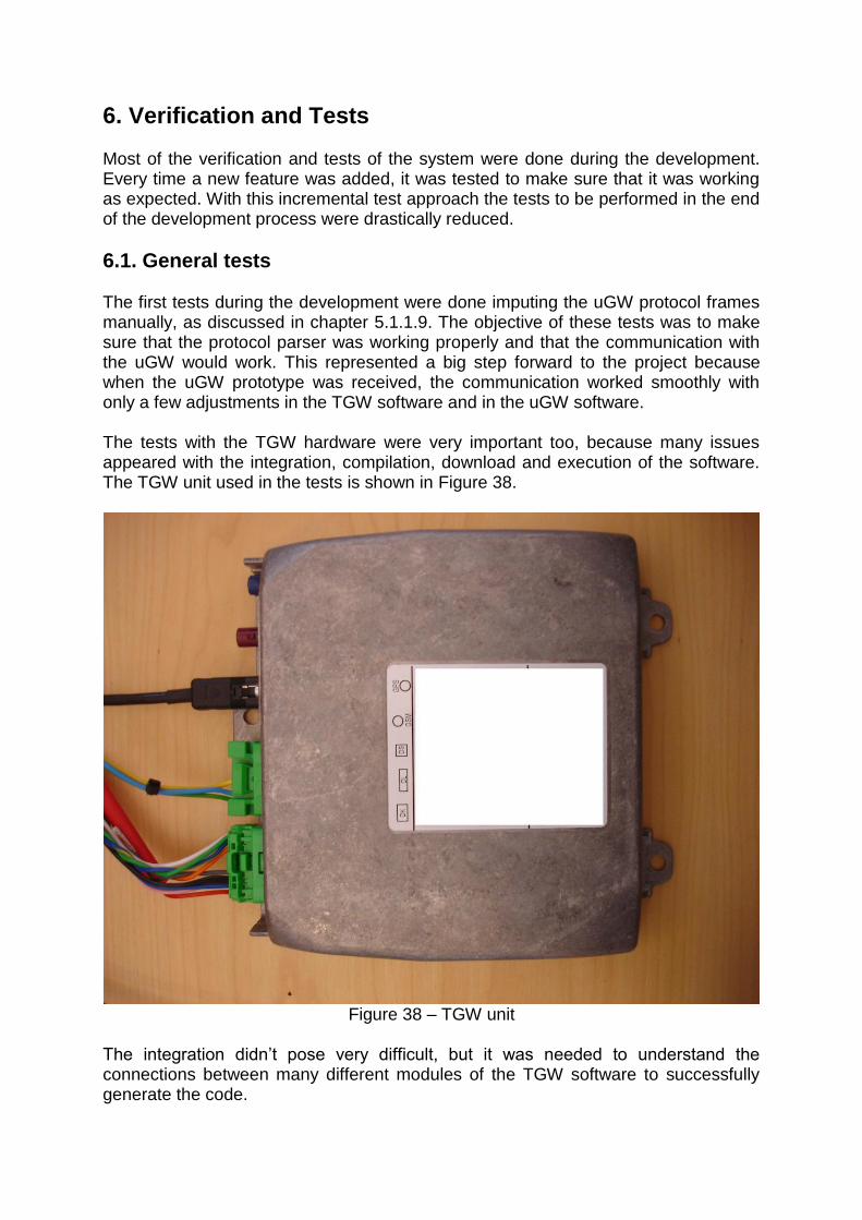
6. Verification and Tests Most of the verification and tests of the system were done during the development. Every time a new feature was added, it was tested to make sure that it was working as expected. With this incremental test approach the tests to be performed in the end of the development process were drastically reduced.
6.1. General tests The first tests during the development were done imputing the uGW protocol frames manually, as discussed in chapter 5.1.1.9. The objective of these tests was to make sure that the protocol parser was working properly and that the communication with the uGW would work. This represented a big step forward to the project because when the uGW prototype was received, the communication worked smoothly with only a few adjustments in the TGW software and in the uGW software. The tests with the TGW hardware were very important too, because many issues appeared with the integration, compilation, download and execution of the software. The TGW unit used in the tests is shown in Figure 38.
Figure 38 – TGW unit
The integration didn’t pose very difficult, but it was needed to understand the connections between many different modules of the TGW software to successfully generate the code.
The compilation was more complicated, since the complete process used to take more than 3 hours in the computer used. After the first compilation, the time was reduced and depended on how many source files were changed. The steps for compiling were: generating the code in Rhapsody, compiling and linking. For more information about how to upgrade the TGW software see Appendix I.
6.2. Sensor tests The tests of the sensor prototypes were performed after the WirelessSensorPkg was in its last steps of development. The objective of these tests was to test and validate the communication with the sensors. Many problems were fixed in the TGW software, in the uGW software and even some bugs in the BitCloud stack. As the sensors responded to all the TGW commands as they should, it was possible to test the timing of all parts of the system and check all layers of the protocol. The initial tests were run using the TGW software compiled for Windows with a serial port sniffer to monitor the communication. To debug the software running the sensor boards, the JTAG interface was used. That made the testing much easier for this part of the system. The communication log for the TGW, uGW and the E-Seal simulator is shown in Appendix V.
7. Closing The last part of the work for this project was to evaluate available hardware for Zigbee devices and prepare a cost estimation for this solution.
7.1. Hardware proposal The idea was to know what hardware is involved to implement a Zigbee sensor or to include in the TGW circuit board for the next generation equipment. As the TGW microcontroller is from the manufacturer Freescale, the initial idea was to have something from the same brand. However, it showed to be more expensive and information about the license for the use of the Zigbee stack from Freescale is not completely available in their website. The solution proposed is based in Atmel parts. The main advantages are the low cost, availability, free and simple Zigbee stack. The experience implementing the sensor prototypes contributed for this choice because the Zigbee stack from Atmel proved to be very simple to work with. The circuit schematic is shown in Appendix VI and the bill of materials in Appendix VII. This solution includes the Zigbee RF hardware, a PCB antenna and the microcontroller with the Zigbee stack. The microcontroller can also be used for other purposes depending on the application. If a new wireless sensor was to be developed with this hardware, the only additional hardware needed would be for the sensor itself. That means that all the hardware for the Zigbee network and the microcontroller are included in this solution. If the support for Zigbee networks was to be included in the TGW circuit board, the proposed solution could be used and connected to the TGW main processor using a USART serial port or an SPI port for instance.
7.2. Cost estimation The component count for this solution is very low, which contributed for having a reduced cost. It has only 3 resistors, 10 small capacitors, 2 ICs and 5 other components, summing 20 parts in total. The estimated total cost for this hardware is only USD 8,23. However, this cost is based on prices available on the internet, which means that it can probably be reduced with higher volumes, supplier agreements etc.
8. Conclusions The achievement of this project is a complete end to end wireless network trial system. From the sensors in one end to the internet portal in the other end, everything was developed. However, the tests were carried out only in simulated environments since the uGW hardware was unsuitable for installation in a real truck. Although the scope of work was changed during the way, the goal of this thesis work is considered to be accomplished. When problems were found, solutions were discussed among the stakeholders and decisions were made on what to do to solve or get around the problems. In the end even without receiving some of the hardware as planned, the demonstration of the system was possible. With this thesis work it was possible to see that the implementation of the software to support Zigbee networks is of medium to low complexity. This implies that with the right level of investment it is possible to develop a complete system within a reasonable time frame. It was also shown that the hardware integration is feasible, with simple circuits, low cost parts and complete support for the Zigbee stack.
8.1. Future Work Although the software developed for the TGW was intended to be a proof of concept, it was developed with the best practices in mind and can be re-used in future projects. In addition the classes were built in a way that new sensors can be added with very little effort. The sensors were developed only as prototypes and the firmware for these devices would have to be improved in order to have real products. The intention of this work was to have the sensors to complete the system and be able to test everything. Although many issues related with Zigbee networks have been studied by others, like Wi-Fi coexistence [30], some additional work is needed regarding tests. When the proper hardware for the uGW is received, it is very advisable to have experiments in real trucks. Radio frequency interference, distance between sensors, mechanics and other issues might arise when the equipment is placed in the actual environment of a truck.
References [1] All, P. Common Wireless Gateway, Volvo Technology, January 2008 [2] Datachassi AB URL: http://www.datachassi.com [verified 2009-10-23] [3] Wikipedia, IEEE 802.15.4-2006 URL: http://en.wikipedia.org/wiki/IEEE_802.15.4-2006 [verified 2009-10-23] [4] IEEE 802.15 Working Group for WPANs URL: http://www.ieee802.org/15/ [verified 2009-10-23] [5] Sullivan, L. Wal-Mart Tests Sensor Networks in Supercenters, Information Week, March 2006 [6] Goode, B. Prediction: Wal-Mart Will Influence Sensors, Sensors Magazine, March 2006 [7] Nucleus RTOS – Mentor Graphics URL: http://www.mentor.com/products/embedded_software/nucleus_rtos/ [verified 2009-10-23] [8] Actia, Telematic Gateway and Terminal Unit System Specification, 2006 [9] Wikipedia, Zigbee URL: http://en.wikipedia.org/wiki/Zigbee [verified 2009-10-23] [10] Wikipedia, Mesh networking URL: http://en.wikipedia.org/wiki/Mesh_networking [verified 2009-10-26] [11] The Zigbee Alliance URL: http://www.zigbee.org [verified 2009-10-23] [12] Daintree Networks, Getting Started with ZigBee and IEEE 802.15.4, 2008 [13] Project Management Institute, Project Management Body of Knowledge, Fourth Edition, 2008 [14] Telelogic (IBM), Rhapsody Getting Started Guide, 2008 [15] Telelogic (IBM), Rhapsody User Guide, 2008 [16] I-Logix (Telelogic IBM), “Essential” Tool Training – Introduction to Rhapsody in C++, 2005 [17] Volvo Technology AB, Dynafleet Evolution On-Board Software Architectural Document (SWAD), 10 October, 2005

[18] Atmel Raven Evaluation Kit URL: http://www.atmel.com/dyn/products/tools_card.asp?tool_id=4291 [verified 2009-11-06] [19] Atmel, AVR2015: RZRAVEN Quick Start Guide, revision B, March 2008 [20] Atmel, AVR2016: RZRAVEN Hardware User's Guide, revision D, April 2008 [21] Atmel, AVR2050: BitCloud User Guide, revision D, May 2009 [22] Atmel, AVR2052: BitCloud Quick Start Guide, revision E, August 2009 [23] Atmel, AVR JTAGICE mkII URL: http://www.atmel.com/dyn/products/tools_card.asp?tool_id=3353, [verified 2009-11-06] [24] Atmel, AVR Studio 4 URL: http://www.atmel.com/dyn/products/tools_card.asp?tool_id=2725, [verified 2009-11-06] [25] Zigbee Alliance, Zigbee Specification, January 17, 2008 [26] Zigbee Alliance, Zigbee Cluster Library Specification, October 19, 2007 [27] Atmel EVK1101 Evaluation Kit URL: http://www.atmel.com/dyn/products/tools_card.asp?tool_id=4175, [verified 2009-11-06] [28] Dresden Elektronik, Radio Controller Board RCB231ED V4.1.1 URL: http://www.dresden-elektronik.de/shop/prod71.html?language=en, [verified 2009-11-06] [29] Atmel, AVR2017: RZRAVEN Firmware, revision A, May 2008 [30] Schneider Electric, Zigbee WiFi Coexistence, April 15, 2008 [31] Volvo Technology AB, Rhapsody Guideline, Dynafleet Evolution, 14 March, 2006 [32] HHD Software, Free Serial Port Monitor URL: http://www.serial-port-monitor.com/index.html, [verified 2009-11-09]

Appendixes
I. TGW Description Confidential Information
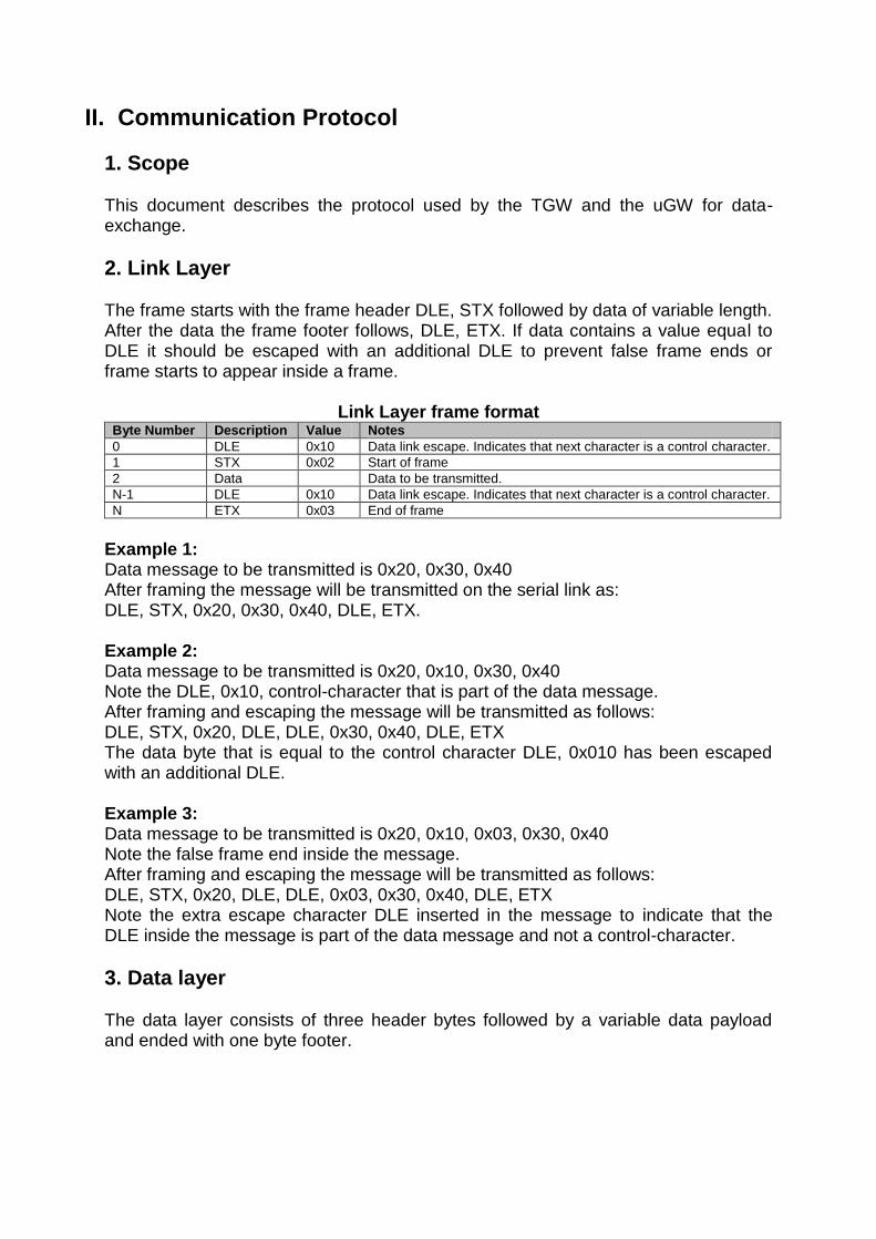
II. Communication Protocol
1. Scope This document describes the protocol used by the TGW and the uGW for data-exchange.
2. Link Layer The frame starts with the frame header DLE, STX followed by data of variable length. After the data the frame footer follows, DLE, ETX. If data contains a value equal to DLE it should be escaped with an additional DLE to prevent false frame ends or frame starts to appear inside a frame.
Link Layer frame format Byte Number Description Value Notes
0 DLE 0x10 Data link escape. Indicates that next character is a control character.
1 STX 0x02 Start of frame
2 Data Data to be transmitted.
N-1 DLE 0x10 Data link escape. Indicates that next character is a control character.
N ETX 0x03 End of frame
Example 1: Data message to be transmitted is 0x20, 0x30, 0x40 After framing the message will be transmitted on the serial link as: DLE, STX, 0x20, 0x30, 0x40, DLE, ETX. Example 2: Data message to be transmitted is 0x20, 0x10, 0x30, 0x40 Note the DLE, 0x10, control-character that is part of the data message. After framing and escaping the message will be transmitted as follows: DLE, STX, 0x20, DLE, DLE, 0x30, 0x40, DLE, ETX The data byte that is equal to the control character DLE, 0x010 has been escaped with an additional DLE. Example 3: Data message to be transmitted is 0x20, 0x10, 0x03, 0x30, 0x40 Note the false frame end inside the message. After framing and escaping the message will be transmitted as follows: DLE, STX, 0x20, DLE, DLE, 0x03, 0x30, 0x40, DLE, ETX Note the extra escape character DLE inserted in the message to indicate that the DLE inside the message is part of the data message and not a control-character.
3. Data layer The data layer consists of three header bytes followed by a variable data payload and ended with one byte footer.

Data Layer frame format Byte Number Description Notes
0 Primitive Indicates the APS primitive.
1 Sequence Sequence number.
2 Data Length Length of the data to be transmitted.
3 Data Data to be transmitted.
N Checksum Checksum of the frame.
When the Not Acknowledgement primitive is received a retransmission of the original message should be done.
3.1. Header The sequence number is incremented every time a message is transmitted. The uGW has one sequence and the TGW has another.
Application Support Sub-Layer (APS) primitives ID Description Notes
0 APSDE-DATA.request From the TGW to the uGW
1 APSDE-DATA.confirm From the uGW to the TGW
2 APSDE-DATA.indication From the uGW to the TGW
3 APSME-UPDATE-DEVICE.request Tells the uGW that the TGW is present
4 APSME-UPDATE-DEVICE.indication
0xFE Not acknowledged Transmitted if data was corrupted, i.e checksum didn’t match.
0xFF Acknowledged Transmitted after receiving a correct data message.
3.2. Footer The footer consists of 1 byte that holds the checksum. The checksum is calculated using 8-bit XOR of all bytes from the data header to the end of the data payload.
4. Application Support Sub-Layer For this first implementation, only a few primitives had to be implemented. Their frame formats and utilization follow the description in items 2.2.4 and 4.4.4 of the Zigbee specification. The fixed addresses in the network are as follows:
Address Description
0x0000 uGW
0x0000 TGW
0xFFFF Broadcast
0xFFFC All lamps and uGW
0xFFFD All nodes with CS_RX_ON_WHEN_IDLE set to true.
The use of the APSME-UPDATE-DEVICE primitive is described in item 4.6.3.2.2 of the Zigbee specification.

4.1. Frame formats The frame format for the APSDE-DATA.request is as follows, according to item 2.2.4.1.1 of the Zigbee specification:
Field
DstAddrMode
DstAddress
DstEndpoint
ProfileId
ClusterId
SrcEndpoint
ADSULength
ADSU
TxOptions
RadiusCounter
The frame format for the APSDE-DATA.confirm is as follows, according to item 2.2.4.1.2 of the Zigbee specification:
Field
DstAddrMode
DstAddress
DstEndpoint
SrcEndpoint
Status
TxTime
The frame format for the APSDE-DATA.indication is as follows, according to item 2.2.4.1.3 of the Zigbee specification:
Field
DstAddrMode
DstAddress
DstEndpoint
SrcAddrMode
SrcAddress
SrcEndpoint
ProfileId
ClusterId
ASDULength
ASDU
Status
SecurityStatus
LinkQuality
RxTime
The frame format for the APSME-UPDATE-DEVICE.request is as follows, according to item 4.4.4.1.1 of the Zigbee specification:

Field
DestAddress
DeviceAddress
Status
DeviceShortAddress
The frame format for the APSME-UPDATE-DEVICE.indication is as follows, according to item 4.4.4.2.1 of the Zigbee specification:
Field
SrcAddress
DeviceAddress
Status
DeviceShortAddress
For the APSDE-DATA frames the ASDULength field should be 1 byte, the security status should also be 1 byte and the rxTime and txTime fields should be 4 bytes. The status field should be 1 byte according to the table below: APS_SUCCESS_STATUS = 0x00, //!<SUCCESS
APS_ASDU_TOO_LONG_STATUS = 0xa0, //!<ASDU_TOO_LONG
APS_DEFRAG_DEFERRED_STATUS = 0xa1, //!<DEFRAG_DEFERRED
APS_DEFRAG_UNSUPPORTED_STATUS = 0xa2, //!<DEFRAG_UNSUPPORTED
APS_ILLEGAL_REQUEST_STATUS = 0xa3, //!<ILLEGAL_REQUEST
APS_INVALID_BINDING_STATUS = 0xa4, //!<INVALID_BINDING
APS_INVALID_GROUP_STATUS = 0xa5, //!<INVALID_GROUP
APS_INVALID_PARAMETER_STATUS = 0xa6, //!<INVALID_PARAMETER
APS_NO_ACK_STATUS = 0xa7, //!<NO_ACK
APS_NO_BOUND_DEVICE_STATUS = 0xa8, //!<NO_BOUND_DEVICE
APS_NO_SHORT_ADDRESS_STATUS = 0xa9, //!<NO_SHORT_ADDRESS
APS_NOT_SUPPORTED_STATUS = 0xaa, //!<NOT_SUPPORTED
APS_SECURED_LINK_KEY_STATUS = 0xab, //!<SECURED_LINK_KEY
APS_SECURED_NWK_KEY_STATUS = 0xac, //!<SECURED_NWK_KEY
APS_SECURITY_FAIL_STATUS = 0xad, //!<SECURITY_FAIL
APS_TABLE_FULL_STATUS = 0xae, //!<TABLE_FULL
APS_UNSECURED_STATUS = 0xaf, //!<UNSECURED
APS_UNSUPPORTED_ATTRIBUTE_STATUS = 0xb0, //!<UNSUPPORTED_ATTRIBUTE
5. Application Layer The application Layer will receive and transmit in the payload (ASDU) of the Application Support Sub-Layer. Each application running on the TGW on its Endpoint will only receive messages addressed to it. The Application Layer will implement a partial ZDO running on endpoint 0 (zero) with only some basic functionality, like information of the Simple Descriptors of each Endpoint for binding purposes.

The uGW will have the complete ZDO and will be responsible for bindings, security, binding table management, network management, service and device discovery, etc. In order to get the necessary information from the partial ZDO running in the Application Layer, the standard Zigbee Device Profile commands will be used. For instance, to get the Simple Descriptor of one endpoint, the command Simple_Desc_req will be issued by the uGW and the TGW will respond with the Simple_Desc_rsp command. If necessary, the partial ZDO can be extended later with more functionality.
5.1. Zigbee Device Profile The list of the Zigbee Device Profile commands supported by the partial ZDO running in endpoint 0 of the TGW are as follows: Supported ZDO commands from the uGW
Command Cluster ID Zigbee Specification
Simple_Desc_req 0x0004 2.4.3.1.5
Active_EP_req 0x0005 2.4.3.1.6
End_Device_Bind_req 0x0020 2.4.3.2.1
Bind_req 0x0021 2.4.3.2.2
Supported ZDO commands from the TGW
Command Cluster ID Zigbee Specification
Simple_Desc_rsp 0x8004 2.4.4.1.5
Active_EP_rsp 0x8005 2.4.4.1.6
End_Device_Bind_rsp 0x8020 2.4.4.2.1
Bind_rsp 0x8021 2.4.4.2.2
The End_Device_Bind_req request frame does not follow the Zigbee standard specification and will have the following format:
Name Type Valid Range Description
Binding Target Device Address 16 bit The address of the target for the binding. This can be either the primary binding cache device or the short address of the local device.
SourceIEEE Address IEEE Address A valid 64 bit IEEE address
IEEE address of the device generating the request
Source Endpoint 8 bits 1-240 The endpoint of the device
Destination Endpoint 8 bits 1-240 The endpoint of the TGW
Profile ID Integer 0x0000 – 0xFFFF Profile ID that matched
NumInClusters Integer 0x00 – 0xFF The number of Input Clusters provided for end device binding within the InClusterList.
InClusterList 2*NumInClusters List of Input ClusterIDs to be used for matching. The InClusterList is the desired list to be matched by the ZigBee coordinator with the Remote Devices output clusters (the elements of the InClusterList are supported input clusters of the Local Device).
NumOutClusters Integer 0x00 – 0xFF The number of Output Clusters provided for end device binding within the OutClusterList.
OutClusterList 2*NumOutClusters List of Output ClusterIDs to be used for matching. The InClusterList is the desired list to be matched by the ZigBee
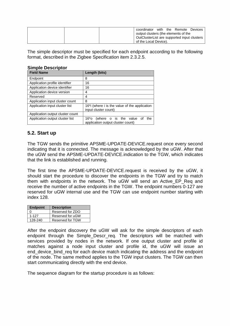
coordinator with the Remote Devices output clusters (the elements of the OutClusterList are supported input clusters of the Local Device).
The simple descriptor must be specified for each endpoint according to the following format, described in the Zigbee Specification item 2.3.2.5. Simple Descriptor
Field Name Length (bits)
Endpoint 8
Application profile identifier 16
Application device identifier 16
Application device version 4
Reserved 4
Application input cluster count 8
Application input cluster list 16*i (where i is the value of the application input cluster count)
Application output cluster count
Application output cluster list 16*o (where o is the value of the application output cluster count)
5.2. Start up The TGW sends the primitive APSME-UPDATE-DEVICE.request once every second indicating that it is connected. The message is acknowledged by the uGW. After that the uGW send the APSME-UPDATE-DEVICE.indication to the TGW, which indicates that the link is established and running. The first time the APSME-UPDATE-DEVICE.request is received by the uGW, it should start the procedure to discover the endpoints in the TGW and try to match them with endpoints in the network. The uGW will send an Active_EP_Req and receive the number of active endpoints in the TGW. The endpoint numbers 0-127 are reserved for uGW internal use and the TGW can use endpoint number starting with index 128.
Endpoint Description
0 Reserved for ZDO
1-127 Reserved for uGW
128-240 Reserved for TGW
After the endpoint discovery the uGW will ask for the simple descriptors of each endpoint through the Simple_Descr_req. The descriptors will be matched with services provided by nodes in the network. If one output cluster and profile id matches against a node input cluster and profile id, the uGW will issue an end_device_bind_req for each device match indicating the address and the endpoint of the node. The same method applies to the TGW input clusters. The TGW can then start communicating directly with the end device. The sequence diagram for the startup procedure is as follows:
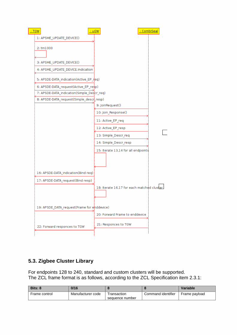
5.3. Zigbee Cluster Library For endpoints 128 to 240, standard and custom clusters will be supported. The ZCL frame format is as follows, according to the ZCL Specification item 2.3.1:
Bits: 8 0/16 8 8 Variable
Frame control Manufacturer code Transaction sequence number
Command identifier Frame payload

The details of each field of the frame can be found in item 2.3.1 of the ZCL Specification. A list of standard commands is presented in item 2.4 of the ZCL Specification. The size in octets of each Data Type will follow item 2.5.2 of the ZCL Specification.

III. Sensors protocol E-Seal Clusters
Cluster Attribute
ID Name ID Name Type Range Value
0x0000 Basic 0x0001 ApplicationVersion Unsigned 8-bit integer 0x00 - 0xff 0x00
0x0000 Basic 0x0003 HWVersion Unsigned 8-bit integer 0x00 - 0xff 0x00
0x0000 Basic 0x0004 ManufacturerName Character string 0 - 32 bytes empty string
0x0000 Basic 0x0005 ModelIdentifier Character string 0 - 32 bytes empty string
0x0000 Basic 0x0007 PowerSource 8-bit Enumeration 0x00 - 0xff 0x00
0x0000 Basic 0x0012 DeviceEnabled Boolean 0x00 – 0x01 0x01
0x0006 On/Off 0x0000 OnOff Boolean 0x00 – 0x01 0x00
0x0500 IAS Zone 0x0002 ZoneStatus bit in 16-bit register 0x0000 – 0xffff 0x00
Movable Panic Button Clusters
Cluster Attribute
ID Name ID Name Type Range Value
0x0000 Basic 0x0001 ApplicationVersion Unsigned 8-bit integer 0x00 - 0xff 0x00
0x0000 Basic 0x0003 HWVersion Unsigned 8-bit integer 0x00 - 0xff 0x00
0x0000 Basic 0x0004 ManufacturerName Character string 0 - 32 bytes empty string
0x0000 Basic 0x0005 ModelIdentifier Character string 0 - 32 bytes empty string
0x0000 Basic 0x0007 PowerSource 8-bit Enumeration 0x00 - 0xff 0x00
0x0000 Basic 0x0012 DeviceEnabled Boolean 0x00 – 0x01 0x01
0x0500 IAS Zone 0x0002 ZoneStatus bit in 16-bit register 0x0000 – 0xffff 0x00
0x1000 Message 0x0000 Message Character string 0 - 32 bytes empty string
Wireless Temperature Sensor Clusters
Cluster Attribute
ID Name ID Name Type Range Value
0x0000 Basic 0x0001 ApplicationVersion Unsigned 8-bit integer 0x00 - 0xff 0x00
0x0000 Basic 0x0003 HWVersion Unsigned 8-bit integer 0x00 - 0xff 0x00
0x0000 Basic 0x0004 ManufacturerName Character string 0 - 32 bytes empty string
0x0000 Basic 0x0005 ModelIdentifier Character string 0 - 32 bytes empty string
0x0000 Basic 0x0007 PowerSource 8-bit Enumeration 0x00 - 0xff 0x00
0x0000 Basic 0x0012 DeviceEnabled Boolean 0x00 – 0x01 0x01
0x1001 Trailer ID 0x0000 Trailer ID Character string 0 - 32 bytes empty string
0x0002 Temperature 0x0000 CurrentTemperature Signed 16-bit integer -200 to +200 0

IV. Example of frames

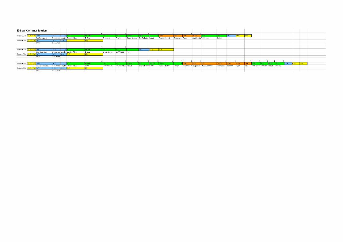
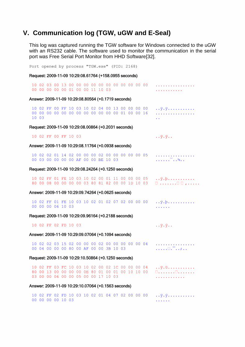
V. Communication log (TGW, uGW and E-Seal) This log was captured running the TGW software for Windows connected to the uGW with an RS232 cable. The software used to monitor the communication in the serial port was Free Serial Port Monitor from HHD Software[32].
Port opened by process "TGW.exe" (PID: 2168)
Request: 2009-11-09 10:29:08.61764 (+158.0955 seconds)
10 02 03 00 13 00 00 00 00 00 00 00 00 00 00 00 ................
00 00 00 00 00 01 00 00 11 10 03 ...........
Answer: 2009-11-09 10:29:08.80564 (+0.1719 seconds)
10 02 FF 00 FF 10 03 10 02 04 00 13 00 00 00 00 ..ÿ.ÿ...........
00 00 00 00 00 00 00 00 00 00 00 00 01 00 00 16 ................
10 03 ..
Request: 2009-11-09 10:29:08.00864 (+0.2031 seconds)
10 02 FF 00 FF 10 03 ..ÿ.ÿ..
Answer: 2009-11-09 10:29:08.11764 (+0.0938 seconds)
10 02 02 01 14 02 00 00 00 02 00 00 00 00 00 05 ................
00 03 00 00 00 00 AF 00 00 BE 10 03 ......¯..¾..
Request: 2009-11-09 10:29:08.24264 (+0.1250 seconds)
10 02 FF 01 FE 10 03 10 02 00 01 11 00 00 00 05 ..ÿ.þ...........
80 00 08 00 00 00 00 03 80 81 82 00 00 1D 10 03 �.......��‚.....
Answer: 2009-11-09 10:29:09.74264 (+0.0625 seconds)
10 02 FF 01 FE 10 03 10 02 01 02 07 02 00 00 00 ..ÿ.þ...........
00 00 00 06 10 03 ......
Request: 2009-11-09 10:29:09.96164 (+0.2188 seconds)
10 02 FF 02 FD 10 03 ..ÿ.ý..
Answer: 2009-11-09 10:29:09.07064 (+0.1094 seconds)
10 02 02 03 15 02 00 00 00 02 00 00 00 00 00 04 ................
00 04 00 00 00 80 00 AF 00 00 3B 10 03 .....€.¯..;..
Request: 2009-11-09 10:29:10.50864 (+0.1250 seconds)
10 02 FF 03 FC 10 03 10 02 00 02 1C 00 00 00 04 ..ÿ.ü...........
80 00 13 00 00 00 00 0E 80 01 00 01 00 10 10 00 €.......€.......
03 00 00 06 00 00 05 00 00 17 10 03 ............
Answer: 2009-11-09 10:29:10.07064 (+0.1563 seconds)
10 02 FF 02 FD 10 03 10 02 01 04 07 02 00 00 00 ..ÿ.ý...........
00 00 00 00 10 03 ......

Request: 2009-11-09 10:29:10.33664 (+0.2656 seconds)
10 02 FF 04 FB 10 03 ..ÿ.û..
Answer: 2009-11-09 10:29:10.46164 (+0.1094 seconds)
10 02 02 05 15 02 00 00 00 02 00 00 00 00 00 04 ................
00 04 00 00 00 81 00 AF 00 00 3C 10 03 .....•.¯..<..
Request: 2009-11-09 10:29:11.82064 (+0.3594 seconds)
10 02 FF 05 FA 10 03 10 02 00 03 1C 00 00 00 04 ..ÿ.ú...........
80 00 13 00 00 00 00 0E 81 00 10 10 01 00 10 10 €.......•.......
00 03 00 00 00 05 00 10 10 00 00 10 10 10 03 ...............
Answer: 2009-11-09 10:29:11.46164 (+0.2031 seconds)
10 02 FF 03 FC 10 03 10 02 01 06 07 02 00 00 00 ..ÿ.ü...........
00 00 00 02 10 03 ......
Request: 2009-11-09 10:29:12.72664 (+0.2656 seconds)
10 02 FF 06 F9 10 03 ..ÿ.ù..
Answer: 2009-11-09 10:29:12.82064 (+0.0938 seconds)
10 02 02 07 15 02 00 00 00 02 00 00 00 00 00 04 ................
00 04 00 00 00 82 00 AF 00 00 3D 10 03 .....‚.¯..=..
Request: 2009-11-09 10:29:12.21164 (+0.3906 seconds)
10 02 FF 07 F8 10 03 10 02 00 04 1C 00 00 00 04 ..ÿ.ø...........
80 00 13 00 00 00 00 0E 82 00 10 10 01 00 10 10 �.......‚.......
00 03 00 00 02 00 01 10 10 00 00 12 10 03 ..............
Answer: 2009-11-09 10:29:13.85164 (+0.2344 seconds)
10 02 FF 04 FB 10 03 10 02 01 08 07 02 00 00 00 ..ÿ.û...........
00 00 00 0C 10 03 ......
Request: 2009-11-09 10:29:13.28964 (+0.4375 seconds)
10 02 FF 08 F7 10 03 ..ÿ.÷..
Answer: 2009-11-09 10:29:31.43064 (+18.0782 seconds)
10 02 02 09 28 02 00 00 00 02 00 00 00 00 00 20 ....(..........
00 17 00 2B 48 88 88 44 44 33 33 22 12 01 80 01 ...+HˆˆDD33"..€.
00 03 00 00 06 00 00 05 00 00 AF 00 00 68 10 03 ..........¯..h..
Request: 2009-11-09 10:29:32.71164 (+0.2813 seconds)
10 02 FF 09 F6 10 03 10 02 00 05 0B 00 00 00 20 ..ÿ.ö..........
80 00 02 00 00 00 00 AC 10 03 €......¬..
Answer: 2009-11-09 10:29:32.24264 (+0.1875 seconds)
10 02 FF 05 FA 10 03 10 02 01 0A 07 02 00 00 00 ..ÿ.ú...........
00 00 00 0E 10 03 ......
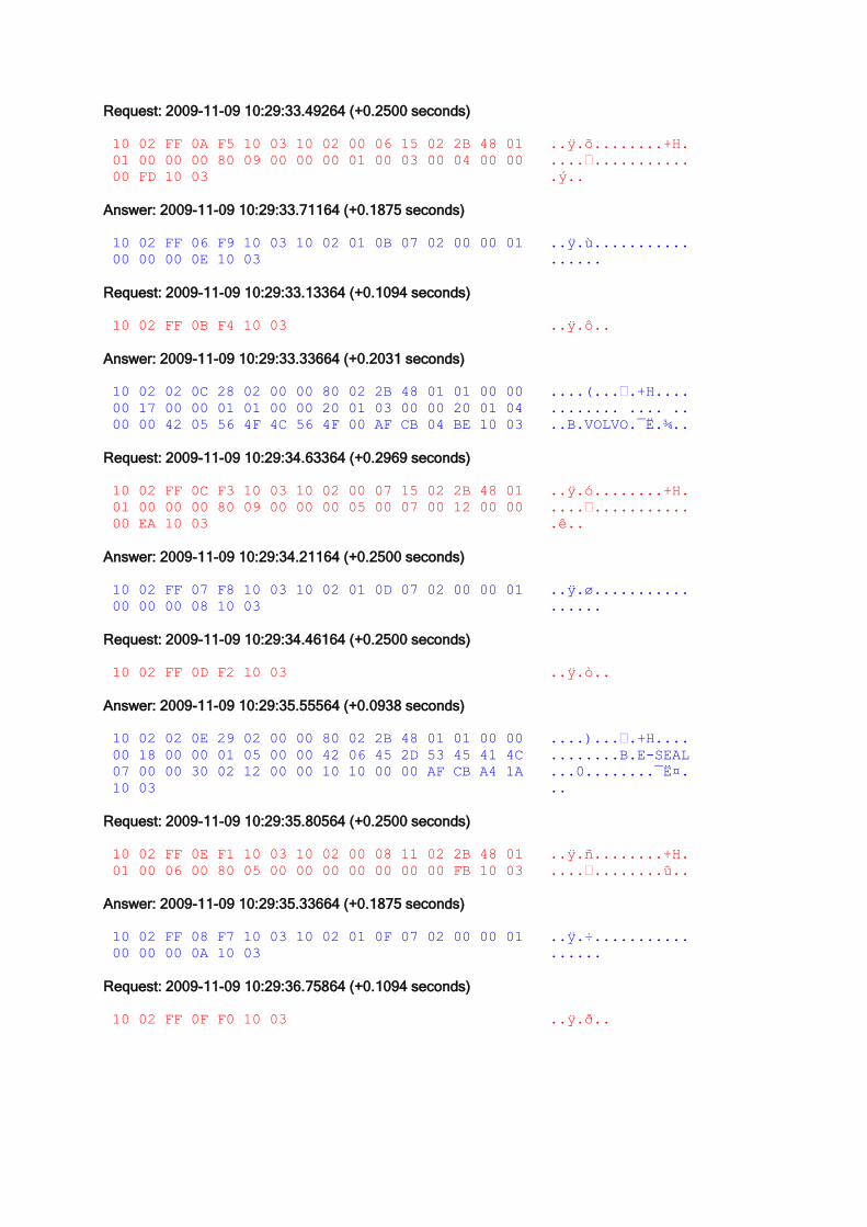
Request: 2009-11-09 10:29:33.49264 (+0.2500 seconds)
10 02 FF 0A F5 10 03 10 02 00 06 15 02 2B 48 01 ..ÿ.õ........+H.
01 00 00 00 80 09 00 00 00 01 00 03 00 04 00 00 ....€...........
00 FD 10 03 .ý..
Answer: 2009-11-09 10:29:33.71164 (+0.1875 seconds)
10 02 FF 06 F9 10 03 10 02 01 0B 07 02 00 00 01 ..ÿ.ù...........
00 00 00 0E 10 03 ......
Request: 2009-11-09 10:29:33.13364 (+0.1094 seconds)
10 02 FF 0B F4 10 03 ..ÿ.ô..
Answer: 2009-11-09 10:29:33.33664 (+0.2031 seconds)
10 02 02 0C 28 02 00 00 80 02 2B 48 01 01 00 00 ....(...€.+H....
00 17 00 00 01 01 00 00 20 01 03 00 00 20 01 04 ........ .... ..
00 00 42 05 56 4F 4C 56 4F 00 AF CB 04 BE 10 03 ..B.VOLVO.¯Ë.¾..
Request: 2009-11-09 10:29:34.63364 (+0.2969 seconds)
10 02 FF 0C F3 10 03 10 02 00 07 15 02 2B 48 01 ..ÿ.ó........+H.
01 00 00 00 80 09 00 00 00 05 00 07 00 12 00 00 ....€...........
00 EA 10 03 .ê..
Answer: 2009-11-09 10:29:34.21164 (+0.2500 seconds)
10 02 FF 07 F8 10 03 10 02 01 0D 07 02 00 00 01 ..ÿ.ø...........
00 00 00 08 10 03 ......
Request: 2009-11-09 10:29:34.46164 (+0.2500 seconds)
10 02 FF 0D F2 10 03 ..ÿ.ò..
Answer: 2009-11-09 10:29:35.55564 (+0.0938 seconds)
10 02 02 0E 29 02 00 00 80 02 2B 48 01 01 00 00 ....)...€.+H....
00 18 00 00 01 05 00 00 42 06 45 2D 53 45 41 4C ........B.E-SEAL
07 00 00 30 02 12 00 00 10 10 00 00 AF CB A4 1A ...0........¯Ë¤.
10 03 ..
Request: 2009-11-09 10:29:35.80564 (+0.2500 seconds)
10 02 FF 0E F1 10 03 10 02 00 08 11 02 2B 48 01 ..ÿ.ñ........+H.
01 00 06 00 80 05 00 00 00 00 00 00 00 FB 10 03 ....€........û..
Answer: 2009-11-09 10:29:35.33664 (+0.1875 seconds)
10 02 FF 08 F7 10 03 10 02 01 0F 07 02 00 00 01 ..ÿ.÷...........
00 00 00 0A 10 03 ......
Request: 2009-11-09 10:29:36.75864 (+0.1094 seconds)
10 02 FF 0F F0 10 03 ..ÿ.ð..

Answer: 2009-11-09 10:29:36.96164 (+0.2031 seconds)
10 02 02 10 10 19 02 00 00 80 02 2B 48 01 01 00 .........€.+H...
06 00 08 00 00 01 00 00 00 10 10 01 00 AF CB 54 .............¯ËT
C6 10 03 Æ..
Request: 2009-11-09 10:29:36.24264 (+0.2813 seconds)
10 02 FF 10 10 EF 10 03 10 02 00 09 11 02 2B 48 ..ÿ..ï........+H
01 01 00 00 05 80 05 00 00 00 02 00 00 00 FB 10 .....€........û.
03 .
Answer: 2009-11-09 10:29:37.74264 (+0.1719 seconds)
10 02 FF 09 F6 10 03 10 02 01 11 07 02 00 00 01 ..ÿ.ö...........
00 00 00 14 10 03 ......
Request: 2009-11-09 10:29:37.14864 (+0.0938 seconds)
10 02 FF 11 EE 10 03 ..ÿ.î..
Answer: 2009-11-09 10:29:37.35264 (+0.1875 seconds)
10 02 02 12 1A 02 00 00 80 02 2B 48 01 01 00 00 ........€.+H....
05 09 00 00 01 02 00 00 19 00 00 00 AF CB E0 7B ............¯Ëà{
10 03 ..
Request: 2009-11-09 10:29:38.57064 (+0.2188 seconds)
10 02 FF 12 ED 10 03 10 02 00 0A 0F 02 2B 48 01 ..ÿ.í........+H.
01 00 06 00 80 03 40 00 01 00 00 A0 10 03 ....€.@.... ..
Answer: 2009-11-09 10:29:38.08664 (+0.1875 seconds)
10 02 FF 0A F5 10 03 10 02 01 13 07 02 00 00 01 ..ÿ.õ...........
00 00 00 16 10 03 ......
Request: 2009-11-09 10:29:39.49264 (+0.0938 seconds)
10 02 FF 13 EC 10 03 ..ÿ.ì..
Answer: 2009-11-09 10:29:39.69564 (+0.1875 seconds)
10 02 02 14 16 02 00 00 80 02 2B 48 01 01 00 06 ........€.+H....
00 05 00 00 0B 01 00 00 AF CC FE 77 10 03 ........¯Ìþw..
Request: 2009-11-09 10:29:39.93064 (+0.2344 seconds)
10 02 FF 14 EB 10 03 10 02 00 0B 13 02 2B 48 01 ..ÿ.ë........+H.
01 00 00 00 80 07 00 00 02 12 00 10 10 01 00 00 ....€...........
FF 10 03 ÿ..
Answer: 2009-11-09 10:29:40.50864 (+0.2344 seconds)
10 02 FF 0B F4 10 03 10 02 01 15 07 02 00 00 01 ..ÿ.ô...........
00 00 00 10 10 10 03 .......
Request: 2009-11-09 10:29:40.72764 (+0.2188 seconds)
10 02 FF 15 EA 10 03 ..ÿ.ê..

Answer: 2009-11-09 10:29:40.82064 (+0.0781 seconds)
10 02 02 16 17 02 00 00 80 02 2B 48 01 01 00 00 ........€.+H....
00 06 00 00 04 00 12 00 00 AF CC 76 E5 10 03 .........¯Ìvå..
Request: 2009-11-09 10:29:40.07064 (+0.2500 seconds)
10 02 FF 16 E9 10 03 ..ÿ.é..
Answer: 2009-11-09 10:30:10.66464 (+29.5939 seconds)
10 02 02 17 17 02 00 00 80 02 2B 48 01 01 00 00 ........€.+H....
05 06 40 00 00 00 00 00 00 AF CD F6 36 10 03 ..@......¯Íö6..
Request: 2009-11-09 10:30:10.77464 (+0.1094 seconds)
10 02 FF 17 E8 10 03 ..ÿ.è..
Answer: 2009-11-09 10:30:40.71164 (+29.9221 seconds)
10 02 02 18 17 02 00 00 80 02 2B 48 01 01 00 00 ........€.+H....
05 06 40 01 00 00 00 00 00 AF CE 76 BB 10 03 ..@......¯Îv»..
Request: 2009-11-09 10:30:40.93064 (+0.2188 seconds)
10 02 FF 18 E7 10 03 ..ÿ.ç..
Answer: 2009-11-09 10:31:01.85264 (+20.8908 seconds)
10 02 02 19 17 02 00 00 80 02 2B 48 01 01 00 00 ........€.+H....
05 06 40 02 00 01 00 00 00 AF CD 78 B5 10 03 ..@......¯Íxµ..
Request: 2009-11-09 10:31:01.35264 (+0.5000 seconds)
10 02 FF 19 E6 10 03 ..ÿ.æ..
Answer: 2009-11-09 10:31:05.89964 (+3.5313 seconds)
10 02 02 1A 17 02 00 00 80 02 2B 48 01 01 00 00 ........€.+H....
05 06 40 03 00 00 00 00 00 AF CD AA 64 10 03 ..@......¯Íªd..
Request: 2009-11-09 10:31:05.00864 (+0.1094 seconds)
10 02 FF 1A E5 10 03 ..ÿ.å..
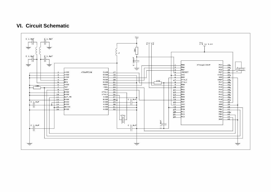
VI. Circuit Schematic

VII. Bill of Materials
Qty Designator Description Manufacturer Part Number Price (USD)
Total Price (USD)
Min Qty
1 L201 SMD RF inductor 0805. Murata BLM21AG102SN1D 0,03850 0,03850 4000
2 L202, L203 RF Inductor, 2.7nH, 0,17ohm, 300mA, 0402 Johanson Technology L-07C2N7SV6T 0,01215 0,02430 10000
1 XC201 16MHz uXtal GSX-323, 2.0 x 2.5 mm SMD 10ppm Golledge GSX-323/111BF 16.0MHz 0,76399 0,76399 3000
1 U201 2.4GHz ZigBee/802.15.4 tranceiver Atmel AT86RF230-ZU 2,06400 2,06400 100
1 XC202 32.768kHz SMD crystal, 85SMX style Rakon Ltd LF XTAL016207 0,65000 0,65000 3000
1 U204 AVR 8-bit RISC MCU Atmel ATmega1284PV-10MU 4,29600 4,29600 4000
Additional components (3 Resistors, 10 Capacitors) 0,39184
Total 8,23
All prices have been collected from the website www.digikey.com during the month of October 2009. The cost of the Additional components is only estimated by being 5% of the total cost of the other components.