wireless switch manager (3wxm) reference manualh20628.wireless switch manager reference manual...
TRANSCRIPT
http://www.3Com.com/
Part No. 10015905Published June 2007
Wireless LAN Mobility SystemWireless Switch ManagerReference Manual
WX4400 3CRWX440095AWX2200 3CRWX220095AWX1200 3CRWX120695AWXR100 3CRWXR10095A
3Com Corporation350 Campus DriveMarlborough, MA USA 01752-3064
Copyright © 2007, 3Com Corporation. All rights reserved. No part of this documentation may be reproduced in any form or by any means or used to make any derivative work (such as translation, transformation, or adaptation) without written permission from 3Com Corporation.
3Com Corporation reserves the right to revise this documentation and to make changes in content from time to time without obligation on the part of 3Com Corporation to provide notification of such revision or change.
3Com Corporation provides this documentation without warranty, term, or condition of any kind, either implied or expressed, including, but not limited to, the implied warranties, terms or conditions of merchantability, satisfactory quality, and fitness for a particular purpose. 3Com may make improvements or changes in the product(s) and/or the program(s) described in this documentation at any time.
If there is any software on removable media described in this documentation, it is furnished under a license agreement included with the product as a separate document, in the hard copy documentation, or on the removable media in a directory file named LICENSE.TXT or !LICENSE.TXT. If you are unable to locate a copy, please contact 3Com and a copy will be provided to you.
UNITED STATES GOVERNMENT LEGEND
If you are a United States government agency, then this documentation and the software described herein are provided to you subject to the following:
All technical data and computer software are commercial in nature and developed solely at private expense. Software is delivered as “Commercial Computer Software” as defined in DFARS 252.227-7014 (June 1995) or as a “commercial item” as defined in FAR 2.101(a) and as such is provided with only such rights as are provided in 3Com’s standard commercial license for the Software. Technical data is provided with limited rights only as provided in DFAR 252.227-7015 (Nov 1995) or FAR 52.227-14 (June 1987), whichever is applicable. You agree not to remove or deface any portion of any legend provided on any licensed program or documentation contained in, or delivered to you in conjunction with, this User Guide.
Unless otherwise indicated, 3Com registered trademarks are registered in the United States and may or may not be registered in other countries.
3Com is a registered trademark of 3Com Corporation. The 3Com logo is a trademark of 3Com Corporation.
Mobility Domain, Mobility Point, Mobility Profile, Mobility System, Mobility System Software, MP, MSS, and SentrySweep are trademarks of Trapeze Networks.
Intel and Pentium are registered trademarks of Intel Corporation. Microsoft, MS-DOS, Windows, Windows XP, and Windows NT are registered trademarks of Microsoft Corporation.
All other company and product names may be trademarks of the respective companies with which they are associated.
ENVIRONMENTAL STATEMENT
It is the policy of 3Com Corporation to be environmentally-friendly in all operations. To uphold our policy, we are committed to:
Establishing environmental performance standards that comply with national legislation and regulations.
Conserving energy, materials and natural resources in all operations.
Reducing the waste generated by all operations. Ensuring that all waste conforms to recognized environmental standards. Maximizing the recyclable and reusable content of all products.
Ensuring that all products can be recycled, reused and disposed of safely.
Ensuring that all products are labelled according to recognized environmental standards.
Improving our environmental record on a continual basis.
End of Life Statement
3Com processes allow for the recovery, reclamation and safe disposal of all end-of-life electronic components.
Regulated Materials Statement
3Com products do not contain any hazardous or ozone-depleting material.
Environmental Statement about the Documentation
The documentation for this product is printed on paper that comes from sustainable, managed forests; it is fully biodegradable and recyclable, and is completely chlorine-free. The varnish is environmentally-friendly, and the inks are vegetable-based with a low heavy-metal content.
CONTENTS
ABOUT THIS GUIDE
Conventions 17Documentation 18Documentation Comments 19
1 INSTALLING 3WXMHardware Requirements 21
Hardware Requirements for 3WXM Client 21Hardware Requirements for 3WXM Monitoring Service 21
Software Requirements 23Preparing for Installation 23
User Privileges 24Serial Number and License Key 24
Installing 3WXM 25Installing 3WXM on Windows Systems 25Installing 3WXM on Linux Systems 27
Installation Log File 28Installing Web-Start Client 29
System Requirements 29Installation Steps 29
Upgrading 3WXM 30Uninstalling 3WXM on Windows Systems 30Uninstalling 3WXM on Linux Systems 32
2 WORKING WITH THE 3WXM USER INTERFACE
Overview 33Display Panels 34
Organizer Panel 35Content Panel 36Task List Panel 38Resizing a Display Panel 39
Menu Bar Options 40Tool Bar Options 42Status Counters 44Copying, Pasting, and Deleting Objects 45
Copy and Paste in the Organizer Panel 46Copy and Paste Replace in the Organizer Panel 46Copy and Paste in the Content Panel 46
Enabling Keyboard Shortcut Mnemonics (Windows XP Only) 47
3 GETTING STARTED
Starting 3WXM 49Restricting Access to 3WXM 54
Creating an Administrator Account 55Creating Provision or Monitor Accounts 56Deleting 3WXM User Accounts 56Disabling Access Control 56
4 WORKING WITH NETWORK PLANS
Creating a Network Plan 58Managing Network Plans 59
Saving a Network Plan 59Opening a Network Plan 60Importing a Network Plan 61Closing a Network Plan 62Deleting a Network Plan 62Sharing a Network Plan 63
Defining a Mobility Domain 64Roaming Behavior 64Traffic Ports Used by MSS 66Creating a Mobility Domain 67Enabling WX-WX Security 67
Creating a WX Switch 68Creating a Third-Party AP 68Changing the Country Code 70Applying the RF Auto-Tuning Settings of a Network Plan to the Network Plan 70Uploading a WX Switch into the Network Plan 71
Converting Auto DAPs into Statically Configured APs 72Creating a Network Domain 72
5 PLANNING THE 3COM MOBILITY SYSTEM
RF Planning Overview 75Accessing the RF Planning Tools 76
Creating or Modifying a Site 78Creating or Modifying Buildings in a Site 80Creating or Modifying Floors 82Importing or Drawing Floor Details 83
Importing a Drawing of a Floor 83File Recommendations 84Preparing a Drawing Before Importing It 84Cropping the Paper Space 89Adjusting the Scale of a Drawing 91Adjusting the Origin Point 91Working with Layers 93Cleaning Up a Drawing 95Drawing Floor Objects Manually 99
Specifying the RF Characteristics of a Floor 100Recommendations 100Converting Objects into RF Obstacles 101Drawing RF Obstacles 103Importing RF Obstacle Data from a Site Survey 104
Defining Wireless Coverage Areas 117Creating a Wiring Closet 117Defining a Coverage Area 119Editing Coverage Areas 132
Placing Third-Party Access Points 137Moving a Third-Party AP Icon to its Floor Location 138Creating and Placing an Icon for a Third-Party Access Point 138
Placing Installed and Auto-Configured MAPs 142Computing MAP Placement 143
Computing and Placing MAP Access Points for a Coverage Area 143Assigning MAP Channels 151Computing Optimal Power 154
Verifying the Wireless Network 157
Showing RF Coverage 157Placing RF Measurement Points 158Using RF Interactive Measurement Mode 160Reading the RF Measurement Table 160
Generating RF Network Design Information 162
6 CONFIGURING WX SYSTEM PARAMETERS
WX Switch Configuration Objects 165Adding a WX Switch to the Network Plan 169
Creating a WX Switch as Part of RF Planning 169Creating a WX Switch Using the Create Wireless Switch Wizard 169Creating a New WX Switch Based on a Configured Switch in the Network Plan 170Adding a Switch by Uploading its Configuration from the Network 171Adding a Switch by Importing a Configuration File 171
Configuring Basic and Advanced Settings 172Reviewing and Deploying Changes 172
Reviewing Changes 172Deploying Changes 172
Using the Create Wireless Switch Wizard 173Setting Up a Switch 175Modifying Basic Switch Parameters 179
Changing the WX Software Version 180Changing the WX Model 180Changing Timezone Properties 181Changing System Information 182Converting Auto DAPs into Statically Configured DAPs 183Removing Auto DAPs 183Launching a Telnet Management Session with the Switch 184Launching a Web Management Session with the Switch 184
Viewing and Changing Port Settings 185Viewing Port Settings 185Changing Port Settings 185Configuring a Port for a Directly Connected AP 187Configure a Port for Wired Authentication 188
Viewing and Changing Port Groups 193Viewing Port Groups 193
Creating a Port Group 193Changing a Port Group 194
Viewing and Changing Management Settings 195Viewing Management Service Settings 195Changing Management Service Settings 195Configuring SNMP 196
Viewing and Setting Log and Trace Settings 207Viewing Log Settings 207Changing Log Settings 207
Viewing and Configuring IP Services Settings 210Viewing IP Services Setting 210Creating a Static Route 211Create an IP Alias 212Configuring DNS 212Configuring NTP 213Configuring ARP 214
Viewing and Configuring VLANs 215Viewing VLANs 216Creating a VLAN 216Changing VLAN Membership 218Changing VLAN Spanning Tree Settings 219Changing VLAN IGMP Settings 223Restricting Layer 2 Traffic Among Clients in a VLAN 226Restricting Layer 3 Traffic Among Clients in a VLAN 227Changing the Tunnel Affinity of a VLAN 227Configuring the MSS DHCP Server 228Changing the Aging Time for FDB Entries 229
Viewing and Configuring ACLs 230Viewing ACLs 230Creating an ACL 231Configuring Advanced ACL Settings 235Adding a New ACE to a Configured ACL 238Mapping an ACL 238Deleting an ACL 240Deleting an Individual ACE from an ACL 240
Viewing and Changing CoS Mappings 241Viewing CoS Mappings 241Changing a DSCP-to-CoS Mapping 242
Changing a CoS-to-DSCP Mapping 242Setting a Range of DSCP Values to a Single CoS Value 243Resetting CoS Mapping to their Default Values 243
7 CONFIGURING WIRELESS PARAMETERS
Viewing and Configuring Wireless Services 245Wireless Service Parameters 246Viewing Wireless Services 251Configuring an 802.1X Wireless Service 251Configuring a Voice over Wireless Service 253Configuring a Web-Portal (WebAAA) Service 256Configuring an Open Access Service 260Configuring a Custom Service 262Modifying Service Profile Settings 262Viewing SSID Encryption Settings and Access Rules 268Modifying SSID Encryption Settings and Access Rules 269
Viewing and Configuring Radio Profiles 272Viewing Radio Profile Settings 272Creating a Radio Profile 273Moving Radios Back to the Default Radio Profile 273Configuring Advanced Radio Profile Settings 274
Viewing and Changing the Auto-DAP Profile 279Viewing Auto-DAP Profile Settings 279Changing Auto-DAP Profile Settings 279Converting Auto DAPs into Statically Configured DAPs 281Removing Auto DAPs 281
Viewing and Configuring MAPs 281Viewing the Configured MAPs 282Creating a Distributed MAP 282Configuring a Directly Connected MAP 284Setting Up AP Redundancy 286Changing the MAP Model 288Changing the Radio Type for an MAP 288Changing the MAP-WX Security Mode 289Configuring Advanced MAP Settings 289
Viewing and Changing Radio Settings 292Viewing Radio Settings 292
Changing Radio Settings 292Viewing and Changing RF Detection Settings 293
Viewing RF Detection Settings 293Adding an Entry to the Permitted Vendor OUI List 293Adding an Entry to the Permitted SSID List 294Adding an Entry to the Ignore List 295Adding an Entry to the Rogue List 295Adding an Entry to the Client Black List 295Enabling Countermeasures 296Enabling MAP Signatures 297
8 CONFIGURING AUTHENTICATION, AUTHORIZATION, AND ACCOUNTING PARAMETERS
Creating and Managing Users in the Local User Database 299Viewing Users and Groups in the Local Database 300Creating a Named User 301Creating a User Group and Assigning Users To It 302Creating a MAC User 303Creating a MAC User Group and Assigning Users To It 304Authorization Attributes 305
Viewing and Configuring RADIUS Settings 311Viewing RADIUS Settings, Servers, and Server Groups 311Creating a RADIUS Server 311Modifying a RADIUS Server 313Creating a RADIUS Server Group 314Changing Default RADIUS Settings 315Configuring RADIUS System Accounting 317
Viewing and Configuring Global 802.1X Settings 317Viewing Global 802.1X Settings 317Changing Global 802.1X Settings 318
Viewing and Configuring 802.1X Network Access Rules 320Viewing 802.1X Network Access Rules 320Creating an 802.1X Network Access Rule 321
Viewing and Configuring MAC Network Access Rules 324Viewing MAC Network Access Rules 324Creating a MAC Network Access Rule 324
Viewing and Configuring WebAAA Network Access Rules 327
Viewing Web AAA Network Access Rules 327Creating a Web AAA Network Access Rule 328
Viewing and Configuring Last-Resort Network Access Rules 330Viewing Last-Resort Network Access Rules 330Creating a Last-Resort Network Access Rule 330
Viewing and Configuring WX Administrator Access Rules 332Viewing WX Administrator Access Rules 332Creating an Access Rule for Console Access 333Creating an Access Rule for Telnet or SSH Access 334
Viewing and Configuring AAA Support for Third-Party AP Users 336Viewing Settings for Third-Party AP AAA Support 336Creating a Proxy Access Rule 336Configuring a RADIUS Proxy for a Client 338Specifying the WX Port Connected to the Third-Party AP 338
Viewing and Changing Location Policy Rules 339Viewing Location Policy Rules 339Creating a Location Policy Rule 340
Viewing and Changing Mobility Profiles 342Viewing Mobility Profiles 342Creating a Mobility Profile 342
9 CONFIGURING WX SWITCHES REMOTELY
How Remote WX Configuration Works 346Drop Ship (WXR100 Only) 346Staged WX 348
3WXM Requirements 349Staging a WX Switch for Configuration by 3WXM 350
Example 1: Deployment Site Has DHCP and Local DNS 350Example 2: Deployment Site Has No DHCP and No DNS 351Example 3: Deployment Site Has DNS But No DHCP 352Example 4: Deployment Site Has DHCP But Local DNS Domain Differs From Corporate DNS Domain 353
Preconfiguring a Switch in 3WXM 354Uploading a Partially Configured Switch and Completing its Configuration with 3WXM 355
Replacing a Switch and Reusing its Configuration 356Requirements 356How Switch Replacement Works 356
Enabling Replacement of Remote Switches 357Replacing a Switch 358
10 MANAGING WX SYSTEM IMAGES AND CONFIGURATIONS
WX File Management Options 359Devices Tab 360
Task List Options 361Toolbar Options 364
Synchronizing Local and Network Changes 365Reviewing Switch Configuration Changes 365Accepting Network Changes 366Undoing Local or Network Changes 366Deploying Switch Configuration Changes 366Synchronizing When the Network and 3WXM Have Nonmatching Changes 368
Distributing System Images 369Using the Image Repository 369Distributing System Images 369
Rebooting WX Switches or MAP Access Points 371Enabling or Disabling Management of a Switch by 3WXM 372Viewing the Operation Log 373Canceling a Scheduled Operation 373Importing and Exporting Switch Configuration Files 374Modifying Configuration Change Polling Options 376
11 VERIFYING CONFIGURATION CHANGES
Verification Tabs 377Toolbar Options 378Filtering the Message List 378
Resolving an Error or Warning 378Disabling a Rule from the Message List 379Changing Verification Options 380Disabling and Reenabling Rules 381
12 MANAGING CERTIFICATES
Overview 383Processing Certificates 384Managing Certificates 385
Reviewing Certificate Details 385Deleting Certificates 385
Distributing Certificates to WX Switches 386
13 CONFIGURING AND APPLYING POLICIES
How Changes Are Managed 387Viewing Policies 387Creating a Policy 388Configuring Feature Settings in a Policy 389Applying Policy Changes to Switches 389
14 MANAGING ALARMS
Setting Up the Fault Management System 391Classifying and Organizing Alarms 393
Search Capabilities 394Fault States 396
Managing Faults 397Alarm Summary 398Top 5 Sources of Alarms 401Intrusion Detection System (IDS) Alarms 402Denial of Service (DoS) Alarms 404
Storing Faults and Retrieving Fault History 404Reporting Faults 406
Alarm Summary Report 406Alarm History Report 408
15 USING THE EVENT LOG
Displaying the Event Log 411Toolbar Options 411
Refreshing Event Data 412Reviewing Event Details 412Filtering Event Messages 412
Using Predefined Event Filters 412Filtering Events by Content 413Filtering Events by Severity 415Filtering Events by Facility 415Creating and Saving Filters 416Deleting Filters 416Exporting Filtered Data 416
16 GENERATING REPORTS
Configuration Requirements 418Overview 419Generating an Inventory Report 420Generating a Mobility Domain Configuration Report 421Generating a WX Configuration Report 422Generating a Client Summary Report 423Generating a Client Details Report 424Generating a Client Errors Report 425Generating an RF Network Usage Report 426Generating an RF Summary Report 427Generating a Radio Details Report 428Generating a Traffic Report 429Generating a Rogue Details Report 430Generating a Rogue Summary Report 430Generating a Site Survey Order 432Generating a Work Order 433Generating an Alarm Summary 434Generating an Alarm History 434Generating a Security Alarm Report 435Generating an Alarm Report for Client OUIs 436
17 MONITORING THE NETWORK
Overview 437Requirements for Monitoring 438
Network Types 438Accessing Monitored Data 439Using the Monitor View 440
Status Summary 441
Alarm Summary 442Client Summary 442Traffic Summary 442
Using the Status Summary View 443Status Monitor or Status Summary Details 444
Using the Alarm Summary View 446Alarm Summary Details 447Additional Alarm Options 451
Using the Client Summary View 453Client Details 454Additional Client Options 455Finding a Client 458Refreshing Client Data 461
Using the Traffic Summary View 462Traffic Details 464Additional Traffic Options 465
Using the Floor View Monitor 466On-Demand Statistics Monitoring 467
Viewing Performance Data 467Creating and Viewing Reports 467
18 DETECTING AND COMBATTING ROGUE DEVICES
Overview 469Rogue Detection Requirements 470
Mobility Domain Requirement 471Rogue Detection Lists 472Displaying Rogue Information 474
Displaying Rogue Details 475Displaying the Geographical Location of a Rogue 478Ignoring Friendly Third-Party Devices 481Adding a Device to the Rogue List 482Converting a Rogue into a Third Party AP 482
To convert a rogue into a third-party AP 482Adding Clients Belonging to a Rogue to the Black List 484Configuring RF Detection Options from the Organizer Panel 484
19 OPTIMIZING A NETWORK PLAN
Importing RF Measurements 485Importing the Measurements 485Applying the RF Measurements to the Floor Plan 487
Locating and Fixing Coverage Holes 488Locating a Coverage Hole 488Fixing a Coverage Hole 490Computing and Placing New MAPs 490Adding New MAPs that Are Already Installed to the Network Plan 490
A CHANGING 3WXM PREFERENCES
Overview 491Resetting Preferences Values 491Changing Network Synchronization Options 492Changing User Interface Options 492Changing Tools Options 493Changing Certificate Management Options 494Changing Options for RF Planning 495
Configuring the Transmit Power of a Typical Client 495Changing Colors 495
Changing 3WXM Logging Options 499
B CHANGING 3WXM SERVICES PREFERENCES
Overview 501Starting or Stopping the 3WXM Services 502
Starting or Stopping 3WXM Services on Windows Systems 503Starting or Stopping 3WXM Services on Linux Systems 504
Connecting to 3WXM Services 504Certificate Check 506
Verifying that the 3WXM Client is Receiving Service Data 507Changing Service Settings 508Changing WX Connection Settings 509Changing Monitoring Settings 510
To change monitoring settings 511Accessing the 3WXM Services Log 513Managing Network Plans 513
Backing Up a Plan 514Changing Backup Settings 514Restoring a Plan from a Backup 514Copying a Plan Backup from One Server to Another 515Deleting a Plan Backup 515
C OBTAINING SUPPORT FOR YOUR 3COM PRODUCTS
Register Your Product to Gain Service Benefits 517Solve Problems Online 517Purchase Extended Warranty and Professional Services 518Access Software Downloads 518Contact Us 519
Telephone Technical Support and Repair 519
INDEX
ABOUT THIS GUIDE
This manual shows you how to plan, configure, deploy, and manage a Mobility System wireless LAN (WLAN) using the 3Com Wireless Switch Manager (3WXM).
Read this manual if you are a network administrator or a person responsible for managing a WLAN.
If release notes are shipped with your product and the information there differs from the information in this guide, follow the instructions in the release notes.
Most user guides and release notes are available in Adobe Acrobat Reader Portable Document Format (PDF) or HTML on the 3Com World Wide Web site:
http://www.3com.com/
Conventions Table 1 and Table 2 list conventions that are used throughout this guide.
Table 1 Notice Icons
Icon Notice Type Description
Information note Information that describes important features or instructions
Caution Information that alerts you to potential loss of data or potential damage to an application, system, or device
18 ABOUT THIS GUIDE
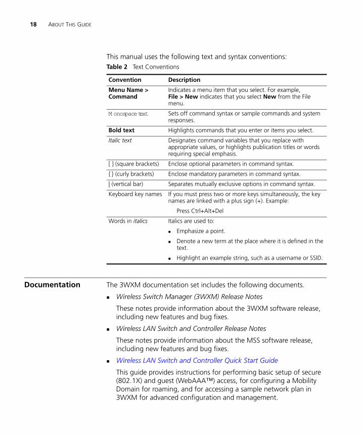
This manual uses the following text and syntax conventions:
Documentation The 3WXM documentation set includes the following documents.
Wireless Switch Manager (3WXM) Release Notes
These notes provide information about the 3WXM software release, including new features and bug fixes.
Wireless LAN Switch and Controller Release Notes
These notes provide information about the MSS software release, including new features and bug fixes.
Wireless LAN Switch and Controller Quick Start Guide
This guide provides instructions for performing basic setup of secure (802.1X) and guest (WebAAA™) access, for configuring a Mobility Domain for roaming, and for accessing a sample network plan in 3WXM for advanced configuration and management.
Table 2 Text Conventions
Convention Description
Menu Name > Command
Indicates a menu item that you select. For example, File > New indicates that you select New from the File menu.
M onospace text Sets off command syntax or sample commands and system responses.
Bold text Highlights commands that you enter or items you select.
Italic text Designates command variables that you replace with appropriate values, or highlights publication titles or words requiring special emphasis.
[ ] (square brackets) Enclose optional parameters in command syntax.
{ } (curly brackets) Enclose mandatory parameters in command syntax.
| (vertical bar) Separates mutually exclusive options in command syntax.
Keyboard key names If you must press two or more keys simultaneously, the key names are linked with a plus sign (+). Example:
Press Ctrl+Alt+Del
Words in italics Italics are used to:
Emphasize a point.
Denote a new term at the place where it is defined in the text.
Highlight an example string, such as a username or SSID.
Documentation Comments 19
Wireless Switch Manager Reference Manual (this guide)
This manual shows you how to plan, configure, deploy, and manage a Mobility System wireless LAN (WLAN) using the 3Com Wireless Switch Manager (3WXM).
Wireless Switch Manager User’s Guide
This guide shows you how to plan, configure, deploy, and manage a Mobility System wireless LAN (WLAN) using the 3Com Wireless Switch Manager (3WXM). It contains information about recommended system requirements you should meet for optimum 3WXM performance, installing 3WXM client and 3WXM Services software, and an introduction to using the 3WXM interface.
Wireless LAN Switch and Controller Hardware Installation Guide
This guide provides instructions and specifications for installing a WX wireless switch in a Mobility System WLAN.
Wireless LAN Switch and Controller Configuration Guide
This guide provides instructions for configuring and managing the system through the Mobility System Software (MSS) CLI.
Wireless LAN Switch and Controller Command Reference
This reference provides syntax information for all MSS commands supported on WX switches.
Documentation Comments
Your suggestions are very important to us. They will help make our documentation more useful to you. Please e-mail comments about this document to 3Com at:
Please include the following information when contacting us:
Document title
Document part number and revision (on the title page)
Page number (if appropriate)
20 ABOUT THIS GUIDE
Example:
Wireless LAN Switch and Controller Configuration Guide
Part number 730-9502-0071, Revision B
Page 25
Please note that we can only respond to comments and questions about 3Com product documentation at this e-mail address. Questions related to Technical Support or sales should be directed in the first instance to your network supplier.
1 INSTALLING 3WXM
This chapter describes how to install 3Com Wireless Switch Manager (3WXM).
Hardware Requirements
HardwareRequirements for
3WXM Client
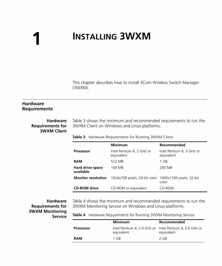
Table 3 shows the minimum and recommended requirements to run the 3WXM Client on Windows and Linux platforms.
HardwareRequirements for
3WXM MonitoringService
Table 4 shows the minimum and recommended requirements to run the 3WXM Monitoring Service on Windows and Linux platforms.
Table 3 Hardware Requirements for Running 3WXM Client
Minimum Recommended
Processor Intel Pentium 4, 2 GHz or equivalent
Intel Pentium 4, 3 GHz or equivalent
RAM 512 MB 1 GB
Hard drive space available
100 MB 200 MB
Monitor resolution 1024x768 pixels, 24-bit color 1600x1200 pixels, 32-bit color
CD-ROM drive CD-ROM or equivalent CD-ROM
Table 4 Hardware Requirements for Running 3WXM Monitoring Service
Minimum Recommended
Processor Intel Pentium 4, 2.4 GHz or equivalent
Intel Pentium 4, 3.6 GHz or equivalent
RAM 1 GB 2 GB
22 CHAPTER 1: INSTALLING 3WXM
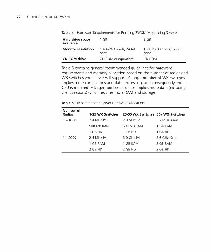
Table 5 contains general recommended guidelines for hardware requirements and memory allocation based on the number of radios and WX switches your server will support. A larger number of WX switches implies more connections and data processing, and consequently, more CPU is required. A larger number of radios implies more data (including client sessions) which requires more RAM and storage
Hard drive space available
1 GB 2 GB
Monitor resolution 1024x768 pixels, 24-bit color
1600x1200 pixels, 32-bit color
CD-ROM drive CD-ROM or equivalent CD-ROM
Table 5 Recommended Server Hardware Allocation
Number of Radios 1-25 WX Switches 25-50 WX Switches 50+ WX Switches
1 – 1000 2.4 MHz P4
500 MB RAM
1 GB HD
2.8 MHz P4
500 MB RAM
1 GB HD
3.2 MHz Xeon
1 GB RAM
1 GB HD
1 – 2000 2.4 MHz P4
1 GB RAM
2 GB HD
3.0 GHz P4
1 GB RAM
2 GB HD
3.6 GHz Xeon
2 GB RAM
2 GB HD
Table 4 Hardware Requirements for Running 3WXM Monitoring Service

Software Requirements 23
Software Requirements
3WXM Client and 3WXM monitoring services are each supported on the following operating systems:
Microsoft Windows Server 2003
Microsoft Windows XP with Service Pack 1 (SP1) or later
Microsoft Windows 2000 with Service Pack 4
SUSE Linux 9.1 and Red Hat WS3, WS4, and ES4
You must use the English version of the operating system you select. Operating system versions in other languages are not supported with 3WXM.
The following additional software is required for certain 3WXM features:
Adobe Acrobat Reader 5.x or later (or plug-in)—For reading the Wireless Switch Manager Reference Manual and release notes.
Web browser (for example, Microsoft Internet Explorer 5.x or 6.x or Netscape Navigator 6.x or 7.x)—For displaying 3WXM work orders and inventory reports.
Preparing for Installation
A licensed copy of 3WXM comes with a base license key. Before you install 3WXM, make sure you have the appropriate administrative privileges on the system.
After you have installed 3WXM, you will need to register your license and the serial number with 3Com in order to obtain an activation key.
The base key along with its activation key enables you to manage up to 10 wireless LAN switches. To manage more than 10 wireless LAN switches, you also need an upgrade key and an additional activation key, which you obtain from 3Com. See “Serial Number and License Key” on page 24 for more information.
24 CHAPTER 1: INSTALLING 3WXM
User Privileges Before you install 3WXM, make sure that you are logged in as a user who has permission to install software, or as an administrator.
After installing 3WXM, configure 3WXM access privileges for the user accounts on the machine and access privileges for the monitoring service, if installed. Access privileges for the 3WXM Client are completely independent of access privileges for the monitoring service, and are configured separately.
Serial Number andLicense Key
3WXM comes with a base license key, which is provided on the CD cover. To use 3WXM Services, you need to enter the base key and an activation key, which you obtain from 3Com. The base key and activation key enable you to manage up to 10 wireless LAN switches.
To manage more than 10 wireless LAN switches, you need an upgrade license. Purchase the 3Com Wireless Switch Manager Upgrade (3WXMUPA) license, which enables 3WXM to manage more than 10 switches and/or controllers. 3Com recommends a maximum of 64 for stable operations with full monitoring.
Each time you connect the 3WXM Client to the 3WXM services, it checks the license information. If the product is not licensed, you will have to install the license on the server machine.
Installing 3WXM 25
Installing 3WXM To install the 3Com Wireless Switch Manager, follow the instructions for your operating system below.
Installing 3WXM onWindows Systems
To install 3WXM on a Windows system:
The 3WXM install program installs either just the 3WXM Client, or both the 3WXM Client and Services. There is no option to install the 3WXM Services only.
1 Insert the 3WXM CD in the CD-ROM drive.
If Autorun is enabled, wait briefly for the install program to start.
If Autorun is disabled, follow these steps:
a In Windows Explorer, navigate to your CD-ROM drive.
b In the Software\3WXM directory, double-click install.exe.
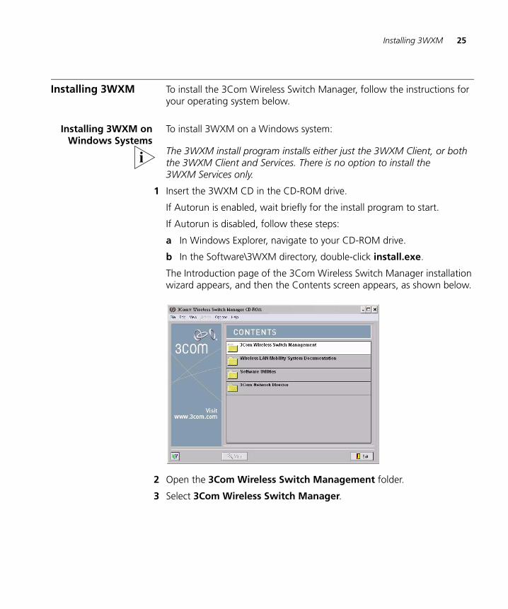
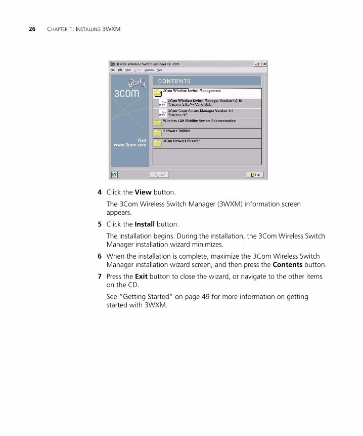
The Introduction page of the 3Com Wireless Switch Manager installation wizard appears, and then the Contents screen appears, as shown below.
2 Open the 3Com Wireless Switch Management folder.
3 Select 3Com Wireless Switch Manager.
26 CHAPTER 1: INSTALLING 3WXM
4 Click the View button.
The 3Com Wireless Switch Manager (3WXM) information screen appears.
5 Click the Install button.
The installation begins. During the installation, the 3Com Wireless Switch Manager installation wizard minimizes.
6 When the installation is complete, maximize the 3Com Wireless Switch Manager installation wizard screen, and then press the Contents button.
7 Press the Exit button to close the wizard, or navigate to the other items on the CD.
See “Getting Started” on page 49 for more information on getting started with 3WXM.
Installing 3WXM 27
Installing 3WXM onLinux Systems
The same 3WXM install program installs either 3WXM Client, 3WXM Services, or both.
To install 3WXM on a Linux system:
Unpack the filesUse the Installation Wizard
Unpacking Files
To unpack files on Linux systems:
1 Log in as superuser.
2 Insert the 3WXM CD in the CD-ROM drive.
3 Browse to the Linux folder: Software\3WXM\Linux
4 Save the installation binary (install.bin) to a temporary location on the hard drive.
5 Open a shell window.
6 Use the cd command to go to the directory in which you saved the installation binary.
7 In the shell window, type sh ./install.bin. The Introduction page of the 3WXM installation wizard appears.
8 Click Next to display the Choose Installation Type page of the installation wizard, and go to “Using the Installation Wizard”.
The installer does not make any path changes during installation. You might want to configure path information, to make 3WXM easy to start on your system. 3WXM must be run at the root level.
Using the Installation Wizard
To use the installation wizard on a Linux system:
1 On the Choose Installation Type page, choose one of the following:
To install both the 3WXM server and the client, click the 3WXM Services icon.
To install only the 3WXM Client, click the 3WXM Client icon.
For detailed installation instructions, see “Installing 3WXM” in the Wireless Switch Manager Reference Manual.
28 CHAPTER 1: INSTALLING 3WXM
Near the end of the installation process, the installer displays the service ports 3WXM Services will use:
443—HTTPS server port
162—SNMP trap receiver port
You can change one or both port numbers to prevent conflicts with other applications on the same host.
Multiple applications cannot use the same UDP or TCP port on the same host. For example, port 443 is defined by the Internet Assigned Numbers Authority (IANA) as the well-known HTTPS port. If the host on which you install 3WXM Services uses its default HTTPS port (443), and the same host also runs Microsoft Internet Information Services (IIS) on its default HTTPS port (443), there will be a conflict over the port. 3WXM clients will not be able to communicate with 3WXM Services.
If you plan to use the remote configuration option to configure new switches, you must use port 443 for 3WXM Services. When a switch requests its configuration from 3WXM Services, it sends the request to port 443.
Installation Log File During installation, an installation log file is created and placed in the 3WXM installation folder. This log file is named 3WXM_InstallLog.log. Double-click the log file icon to read the file. Have this log file available if you need to contact 3Com Technical Support about an installation problem.
Installing Web-Start Client 29
Installing Web-Start Client
3WXM version 5.0 provides a Java-based version of the 3WXM Client, the Web-Start client.
The Web-Start client simplifies installation and upgrade of the client. Because the client and server versions must match, an upgrade to 3WXM Services requires an upgrade of the client on each machine to the same version.
The versions of the client and server also must match when the client is Java-based. However, you can easily install the Web-Start client simply by browsing to the server and clicking an option. You do not need to install from the product CD or an installation executable stored on a file server.
The appearance and options in the Java version of the client are identical to those in the standard version.
System Requirements A Java plug-in is required. You cannot launch the Web-Start client using a Java-enabled web browser.
One of the following browsers is required:
Internet Explorer 5.5 or higher
Mozilla Firefox 1.5 or higher
Installation Steps To install the Web-Start client:
1 Use a browser to establish a secure (HTTPS) connection to the host running 3WXM Services.
2 Select the Home option.
3 Click Launch Client.
30 CHAPTER 1: INSTALLING 3WXM
Upgrading 3WXM To upgrade 3WXM, install a newer version of 3WXM over a previous version. You do not need to uninstall the previous version before installing a newer version. Before upgrading, make a backup of the config-db directory in the 3WXM installation directory. As a best practice, back up the config-db directory on a regular basis to ensure that you have copies of your network plans.
CAUTION: If you uninstall a previous version of 3WXM before upgrading, make sure you note the serial number and license key from the License Information dialog box, which you access by selecting Help>Licensing from the main 3WXM window.
You can also save a copy of the license information by starting 3WXM and clicking Save in the License Information dialog box.
Uninstalling 3WXM on Windows Systems
To upgrade 3WXM, install a newer version over a previous version. You do not need to uninstall the previous version before installing a newer version.
If you do want to uninstall 3WXM, use the Uninstall wizard. Access the Uninstall wizard from the 3Com program list in the Windows Start menu or the Control Panel.
To uninstall 3WXM on Windows systems:
1 Access the Windows Control Panel, and select Add or Remove Programs.
2 Select 3WXM and click Change/Remove.
Uninstalling 3WXM on Windows Systems 31
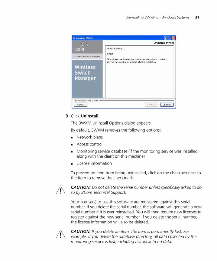
3 Click Uninstall.
The 3WXM Uninstall Options dialog appears.
By default, 3WXM removes the following options:
Network plans
Access control
Monitoring service database (if the monitoring service was installed along with the client on this machine)
License information
To prevent an item from being uninstalled, click on the checkbox next to the item to remove the checkmark.
CAUTION: Do not delete the serial number unless specifically asked to do so by 3Com Technical Support.
Your license(s) to use this software are registered against this serial number. If you delete the serial number, the software will generate a new serial number if it is ever reinstalled. You will then require new licenses to register against the new serial number. If you delete the serial number, the license information will also be deleted.
CAUTION: If you delete an item, the item is permanently lost. For example, if you delete the database directory, all data collected by the monitoring service is lost, including historical trend data.
32 CHAPTER 1: INSTALLING 3WXM
To prevent an item from being uninstalled, click on the checkbox next to the item to remove the checkmark.
4 Click Continue.
The uninstall program reports its progress. When the uninstall process is complete, the uninstall program reports that the items were successfully deleted.
5 Click Done.
Uninstalling 3WXM on Linux Systems
To uninstall 3WXM on Linux systems:
1 Log in as superuser.
2 In a shell window, change directories to the 3WXM installation directory.
By default, the installation directory is /opt/3wxm.
3 At the prompt, enter cd UninstallerData.
4 At the prompt, enter ./Uninstall_3WXM.
The Uninstall wizard appears.
5 Click Uninstall.
The 3WXM Uninstall Options dialog appears. By default, all 3WXM removes the following options:
Network plans
Access control
Monitoring service database (if the monitoring service was installed along with the client on this machine)
License information
To prevent an item from being uninstalled, click on the checkbox next to the item to remove the checkmark.
The monitoring service plug-in is uninstalled automatically.
CAUTION: If you delete an item, the item is permanently lost. For example, if you delete the database directory, all data collected by the monitoring service is lost, including historical trend data.
6 Click Continue.
The uninstall program reports its progress.
7 Click Done.
2 WORKING WITH THE 3WXM USER INTERFACE
This chapter describes how to use the 3Com Wireless Switch Manager (3WXM) interface.
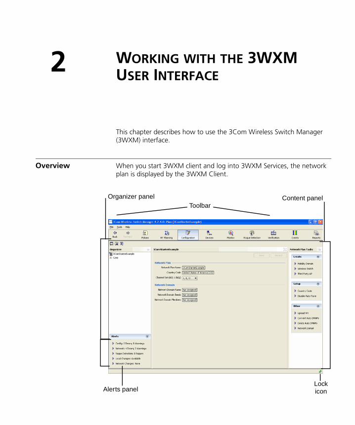
Overview When you start 3WXM client and log into 3WXM Services, the network plan is displayed by the 3WXM Client.
ToolbarOrganizer panel Content panel
Alerts panelLockicon
34 CHAPTER 2: WORKING WITH THE 3WXM USER INTERFACE
The network plan is the workspace in 3WXM you use to design and manage a 3Com network. The network plan defines the following:
Network equipment (WX switches, MAPs, and third-party access points)
Network site, including floor plans, RF characteristics of the floors, and radio coverage
Use the planning tool to define the network site and add the equipment based on coverage and capacity needs. Alternatively, add new or existing switches and access points individually.
Planning and equipment configuration, and network management, are described in detail in other chapters of this manual. This chapter describes the 3WXM user interface.
Display Panels The main 3WXM window contains the following display panels. (Their locations are shown in the previous figure on page 34.)
Organizer panel
Content panel
Task List panel
The main 3WXM window also contains a tool bar to navigate to major features, a menu bar to access management options, and status counters for more information.
Display Panels 35
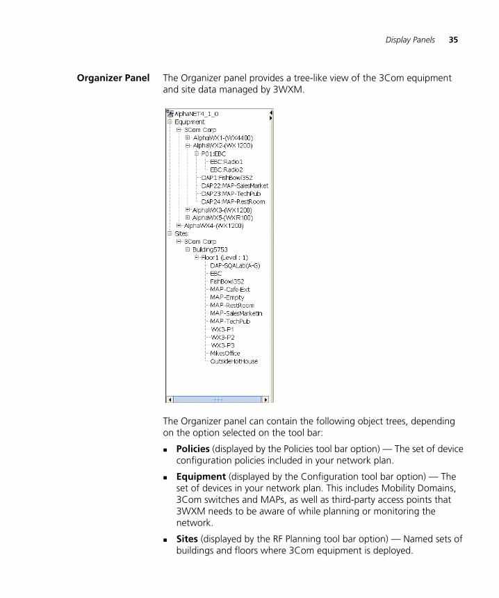
Organizer Panel The Organizer panel provides a tree-like view of the 3Com equipment and site data managed by 3WXM.
The Organizer panel can contain the following object trees, depending on the option selected on the tool bar:
Policies (displayed by the Policies tool bar option) — The set of device configuration policies included in your network plan.
Equipment (displayed by the Configuration tool bar option) — The set of devices in your network plan. This includes Mobility Domains, 3Com switches and MAPs, as well as third-party access points that 3WXM needs to be aware of while planning or monitoring the network.
Sites (displayed by the RF Planning tool bar option) — Named sets of buildings and floors where 3Com equipment is deployed.
36 CHAPTER 2: WORKING WITH THE 3WXM USER INTERFACE
The tree that is displayed depends on the active tool bar option. (See “Tool Bar Options” on page 42.)
To expand the view of an object in the tree, click on the plus sign next to the object. For example, to display the buildings in a site, click on the plus sign next to the site name. To display the floors in the building, click next to the building name, and so on.
Content Panel The Content panel displays information or configuration settings, based on the selected tool bar option. The Content panel is located to the right of the Organizer panel. (See the figure on page 33.)
The Policies, RF Planning, and Configuration tool bar options display configuration fields. After selecting one of these tool bar options, click on a policy, WX switch, or site object in the Organizer panel to display and configure settings for that object.
(For more information about the tool bar options, see “Tool Bar Options” on page 42.)
Saving or Discarding Configuration Changes
When you select the Policies, RF Planning, or Configuration tool bar option, the Content panel contains a Save button and a Discard button.
Save—Click Save to send unsaved configuration changes to 3WXM Services to save in the network plan. The 3WXM Client buffers configuration changes you make to a policy, WX switch, or site until you click Save or save the network plan. When you click Save, the client sends all buffered configuration changes.
Discard—Click Discard to undo all buffered changes.
The Save and Discard buttons are greyed out unless there are unsaved changes.
Configuration wizards have a Finish or OK button, which saves the configuration items you type or select in the wizard.
When you save changes in a wizard by clicking Finish or OK, the Save and Discard buttons in the Content panel remain greyed out because there are no unsaved changes to save or discard.
Display Panels 37
When you click a link to open a configuration wizard, if there are unsaved changes, 3WXM prompts you to apply or cancel the changes. Click Apply to save the buffered changes and open the wizard.
The Save, Apply, Finish, and OK buttons do not send configuration changes to the WX switches in the network. To send changes made in the network plan to switches in the network, deploy the changes. (See “Reviewing and Deploying Switch Configuration Changes”.)
Reviewing and Deploying Switch Configuration Changes
3WXM does not automatically deploy switch configuration changes from the network plan to the actual switches in the network. The following options in the Task List panel allow you to review and deploy changes:
Review—Displays a categorized list of the undeployed changes.
Deploy—Sends the changes to the network.
When you click Deploy, 3WXM verifies the configuration changes and displays warnings or errors if applicable. If any errors are listed, 3WXM does not deploy the changes.
To resolve errors and deploy the changes, use the Verification option. The Verification option provides detailed information for errors and warnings and enables you to resolve them. Generally, you can resolve an error or warning by ignoring it or by clicking a link to open a configuration wizard. (For more information, see Chapter 11.)
38 CHAPTER 2: WORKING WITH THE 3WXM USER INTERFACE
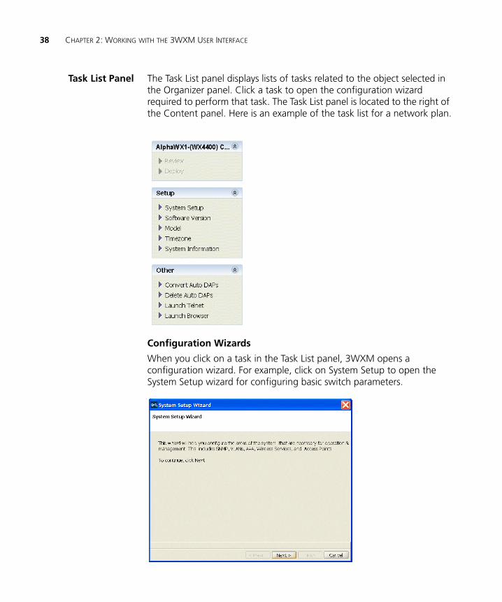
Task List Panel The Task List panel displays lists of tasks related to the object selected in the Organizer panel. Click a task to open the configuration wizard required to perform that task. The Task List panel is located to the right of the Content panel. Here is an example of the task list for a network plan.
Configuration Wizards
When you click on a task in the Task List panel, 3WXM opens a configuration wizard. For example, click on System Setup to open the System Setup wizard for configuring basic switch parameters.
Display Panels 39
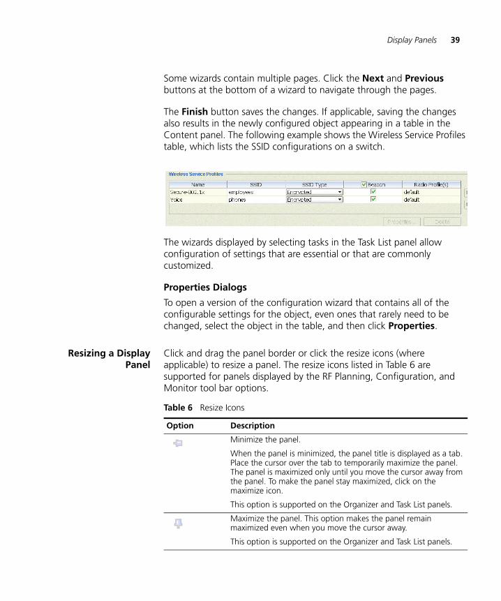
Some wizards contain multiple pages. Click the Next and Previous buttons at the bottom of a wizard to navigate through the pages.
The Finish button saves the changes. If applicable, saving the changes also results in the newly configured object appearing in a table in the Content panel. The following example shows the Wireless Service Profiles table, which lists the SSID configurations on a switch.
The wizards displayed by selecting tasks in the Task List panel allow configuration of settings that are essential or that are commonly customized.
Properties Dialogs
To open a version of the configuration wizard that contains all of the configurable settings for the object, even ones that rarely need to be changed, select the object in the table, and then click Properties.
Resizing a DisplayPanel
Click and drag the panel border or click the resize icons (where applicable) to resize a panel. The resize icons listed in Table 6 are supported for panels displayed by the RF Planning, Configuration, and Monitor tool bar options.
Table 6 Resize Icons
Option Description
Minimize the panel.
When the panel is minimized, the panel title is displayed as a tab. Place the cursor over the tab to temporarily maximize the panel. The panel is maximized only until you move the cursor away from the panel. To make the panel stay maximized, click on the maximize icon.
This option is supported on the Organizer and Task List panels.
Maximize the panel. This option makes the panel remain maximized even when you move the cursor away.
This option is supported on the Organizer and Task List panels.
40 CHAPTER 2: WORKING WITH THE 3WXM USER INTERFACE
Panel sizes and window arrangements are associated with 3WXM usernames. When you close 3WXM, 3WXM remembers the panel sizes and window arrangements you assigned and restores them the next time you run 3WXM.
Menu Bar Options Table 7 lists the options available from the menu at the top of the main 3WXM window. Click on a menu category to display the options for that category.
Maximize the Content panel. The panel fills the entire display area and minimizes the Organizer and Task List panels.
This option applies only to the Content panel.
Restore the Content panel. The Organizer and Task List panels are maximized and the Content panel is restored to its former size between the other two panels.
This option applies only to the Content panel.
Table 6 Resize Icons (continued)
Option Description
Table 7 3WXM Menu Options
Menu Option Description
File Connect Log on to 3WXM Services.
Close Close the currently open network plan.
Exit Close 3WXM.
Services Licensing Open the License Information page.
Setup Open page to configure preferences for 3WXM services.
Plan Management Open the Plan Management page of 3WXM Services.
Backup & Restore Open page to configure settings for backing up the database used by 3WXM services, as well as restore a previously backed-up version of the database.
Lock Management Open page to display information about the lock placed on the network plan and/or delete the lock.
Menu Bar Options 41
Tools Preferences Change 3WXM user preferences.
Certificates Manage certificates
Events Display the events log. The log includes events generated by 3WXM Services and events generated by the managed WX switches in the network plan.
To filter the message list, use the Filters tab.
To display more information about a message, click on the row containing the message, then use the Details tab.
(See “Displaying the Event Log” on page 411.)
Import Import an WX configuration file into the currently open network plan.
Export Export an WX configuration file from the currently open network plan.
Help Help Open the online help (HTML version of the 3Com WXM Reference Manual).
You also can access the help by pressing the F1 key.
Report Problem Report a problem to 3Com Technical Support.
About 3WXM About 3WXM:
3WXM version information
Memory usage
Java garbage collection (Force GC)
Table 7 3WXM Menu Options (continued)
Menu Option Description
42 CHAPTER 2: WORKING WITH THE 3WXM USER INTERFACE
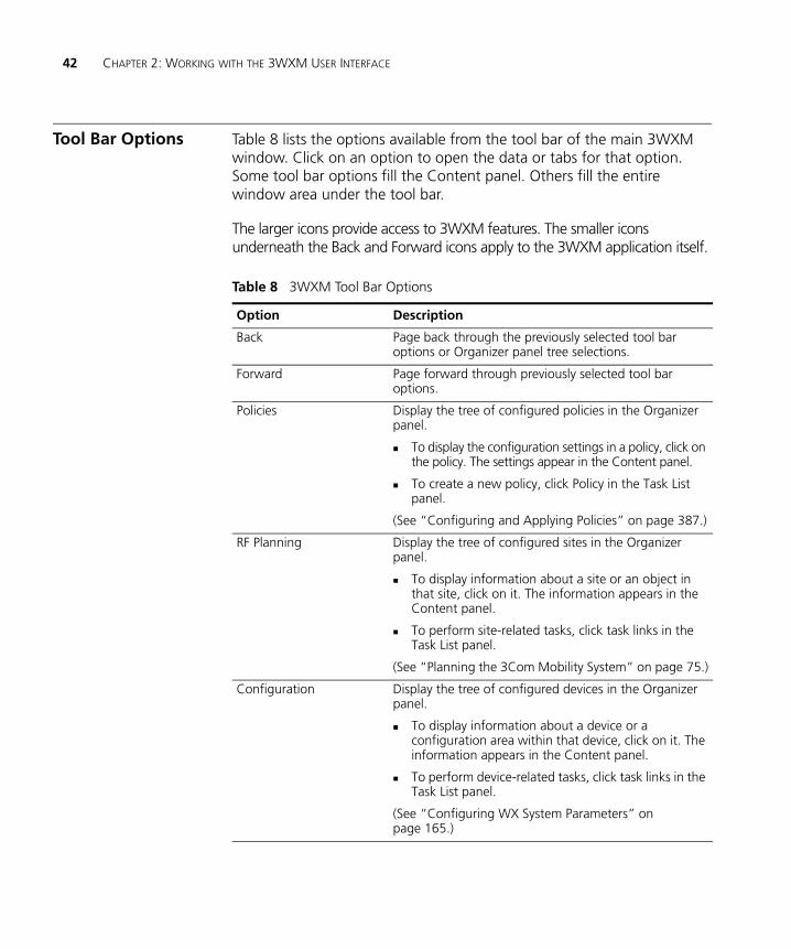
Tool Bar Options Table 8 lists the options available from the tool bar of the main 3WXM window. Click on an option to open the data or tabs for that option. Some tool bar options fill the Content panel. Others fill the entire window area under the tool bar.
The larger icons provide access to 3WXM features. The smaller icons underneath the Back and Forward icons apply to the 3WXM application itself.
Table 8 3WXM Tool Bar Options
Option Description
Back Page back through the previously selected tool bar options or Organizer panel tree selections.
Forward Page forward through previously selected tool bar options.
Policies Display the tree of configured policies in the Organizer panel.
To display the configuration settings in a policy, click on the policy. The settings appear in the Content panel.
To create a new policy, click Policy in the Task List panel.
(See “Configuring and Applying Policies” on page 387.)
RF Planning Display the tree of configured sites in the Organizer panel.
To display information about a site or an object in that site, click on it. The information appears in the Content panel.
To perform site-related tasks, click task links in the Task List panel.
(See “Planning the 3Com Mobility System” on page 75.)
Configuration Display the tree of configured devices in the Organizer panel.
To display information about a device or a configuration area within that device, click on it. The information appears in the Content panel.
To perform device-related tasks, click task links in the Task List panel.
(See “Configuring WX System Parameters” on page 165.)
Tool Bar Options 43
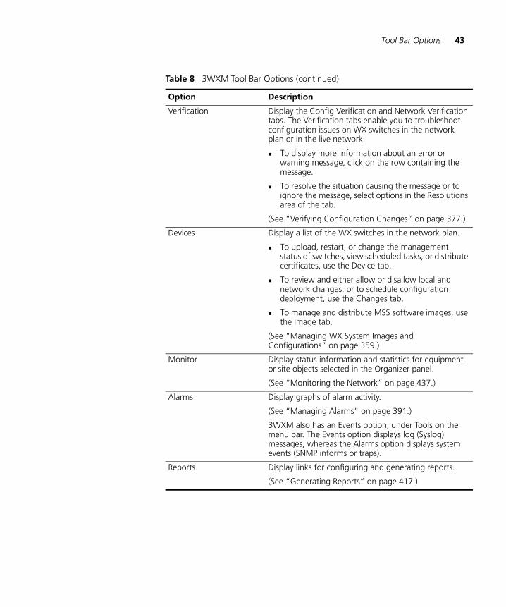
Verification Display the Config Verification and Network Verification tabs. The Verification tabs enable you to troubleshoot configuration issues on WX switches in the network plan or in the live network.
To display more information about an error or warning message, click on the row containing the message.
To resolve the situation causing the message or to ignore the message, select options in the Resolutions area of the tab.
(See “Verifying Configuration Changes” on page 377.)
Devices Display a list of the WX switches in the network plan.
To upload, restart, or change the management status of switches, view scheduled tasks, or distribute certificates, use the Device tab.
To review and either allow or disallow local and network changes, or to schedule configuration deployment, use the Changes tab.
To manage and distribute MSS software images, use the Image tab.
(See “Managing WX System Images and Configurations” on page 359.)
Monitor Display status information and statistics for equipment or site objects selected in the Organizer panel.
(See “Monitoring the Network” on page 437.)
Alarms Display graphs of alarm activity.
(See “Managing Alarms” on page 391.)
3WXM also has an Events option, under Tools on the menu bar. The Events option displays log (Syslog) messages, whereas the Alarms option displays system events (SNMP informs or traps).
Reports Display links for configuring and generating reports.
(See “Generating Reports” on page 417.)
Table 8 3WXM Tool Bar Options (continued)
Option Description
44 CHAPTER 2: WORKING WITH THE 3WXM USER INTERFACE
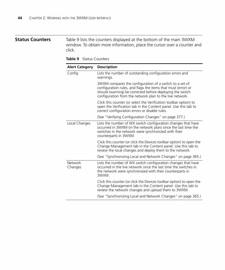
Status Counters Table 9 lists the counters displayed at the bottom of the main 3WXM window. To obtain more information, place the cursor over a counter and click.
Table 9 Status Counters
Alert Category Description
Config Lists the number of outstanding configuration errors and warnings.
3WXM compares the configuration of a switch to a set of configuration rules, and flags the items that must (error) or should (warning) be corrected before deploying the switch configuration from the network plan to the live network.
Click this counter (or select the Verification toolbar option) to open the Verification tab in the Content panel. Use this tab to correct configuration errors or disable rules.
(See “Verifying Configuration Changes” on page 377.)
Local Changes Lists the number of WX switch configuration changes that have occurred in 3WXM (in the network plan) since the last time the switches in the network were synchronized with their counterparts in 3WXM.
Click this counter (or click the Devices toolbar option) to open the Change Management tab in the Content panel. Use this tab to review the local changes and deploy them to the network.
(See “Synchronizing Local and Network Changes” on page 365.)
Network Changes
Lists the number of WX switch configuration changes that have occurred in the live network since the last time the switches in the network were synchronized with their counterparts in 3WXM.
Click this counter (or click the Devices toolbar option) to open the Change Management tab in the Content panel. Use this tab to review the network changes and upload them to 3WXM.
(See “Synchronizing Local and Network Changes” on page 365.)
Copying, Pasting, and Deleting Objects 45
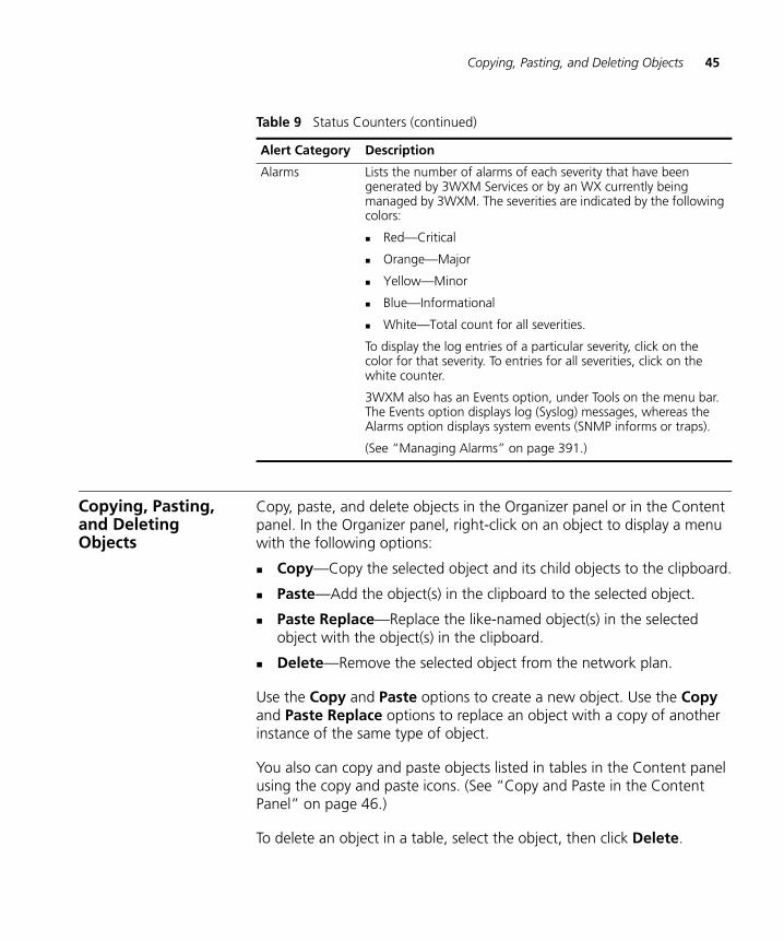
Copying, Pasting, and Deleting Objects
Copy, paste, and delete objects in the Organizer panel or in the Content panel. In the Organizer panel, right-click on an object to display a menu with the following options:
Copy—Copy the selected object and its child objects to the clipboard.
Paste—Add the object(s) in the clipboard to the selected object.
Paste Replace—Replace the like-named object(s) in the selected object with the object(s) in the clipboard.
Delete—Remove the selected object from the network plan.
Use the Copy and Paste options to create a new object. Use the Copy and Paste Replace options to replace an object with a copy of another instance of the same type of object.
You also can copy and paste objects listed in tables in the Content panel using the copy and paste icons. (See “Copy and Paste in the Content Panel” on page 46.)
To delete an object in a table, select the object, then click Delete.
Alarms Lists the number of alarms of each severity that have been generated by 3WXM Services or by an WX currently being managed by 3WXM. The severities are indicated by the following colors:
Red—Critical
Orange—Major
Yellow—Minor
Blue—Informational
White—Total count for all severities.
To display the log entries of a particular severity, click on the color for that severity. To entries for all severities, click on the white counter.
3WXM also has an Events option, under Tools on the menu bar. The Events option displays log (Syslog) messages, whereas the Alarms option displays system events (SNMP informs or traps).
(See “Managing Alarms” on page 391.)
Table 9 Status Counters (continued)
Alert Category Description
46 CHAPTER 2: WORKING WITH THE 3WXM USER INTERFACE
Copy and Paste in theOrganizer Panel
To create a new object in the Organizer panel:
1 Select the object you want to copy in the Organizer panel.
2 Right-click on the object and select Copy.
3 Select the parent object where you want the copy to go.
4 Right-click on the parent object and select Paste.
3WXM displays a configuration wizard. Use this configuration wizard to modify the name of the object and other parameters as applicable. When you are finished, the new copy of the object appears under the parent object.
Copy and PasteReplace in the
Organizer Panel
To replace an object with the Copy and Paste Replace options:
1 Select the object you want to copy in the Organizer panel.
2 Right-click on the object and select Copy.
3 Select the object you want to replace.
4 Right-click on the parent object and select Paste Replace.
3WXM displays a configuration wizard. Use this configuration wizard to modify the name of the object and other parameters if needed. When you are finished, the replaced object is removed and the copied object appears under the parent object.
Copy and Paste in theContent Panel
1 Select the objects (rows).
To select a single object, click on the row for the object.
To select multiple contiguous objects, click Shift while selecting them.
To select multiple noncontiguous objects, click Ctrl while selecting them.
2 Click the copy icon ( ).
Enabling Keyboard Shortcut Mnemonics (Windows XP Only) 47
3 Click the paste icon ( ).
A configuration wizard appears.
4 Edit settings to make the new object unique from the object you copied, then click OK or Finish to save the changes and close the configuration wizard.
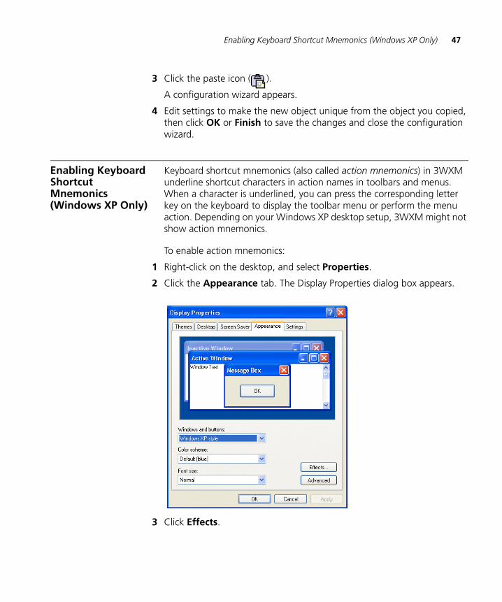
Enabling Keyboard Shortcut Mnemonics (Windows XP Only)
Keyboard shortcut mnemonics (also called action mnemonics) in 3WXM underline shortcut characters in action names in toolbars and menus. When a character is underlined, you can press the corresponding letter key on the keyboard to display the toolbar menu or perform the menu action. Depending on your Windows XP desktop setup, 3WXM might not show action mnemonics.
To enable action mnemonics:
1 Right-click on the desktop, and select Properties.
2 Click the Appearance tab. The Display Properties dialog box appears.
3 Click Effects.
48 CHAPTER 2: WORKING WITH THE 3WXM USER INTERFACE
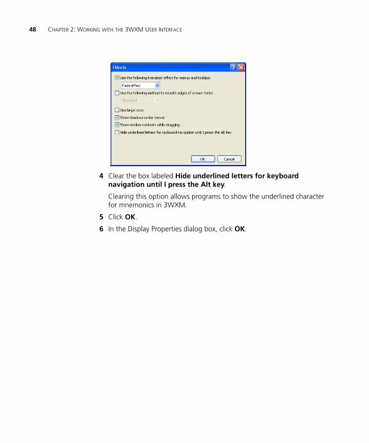
4 Clear the box labeled Hide underlined letters for keyboard navigation until I press the Alt key.
Clearing this option allows programs to show the underlined character for mnemonics in 3WXM.
5 Click OK.
6 In the Display Properties dialog box, click OK.
3 GETTING STARTED
This chapter contains information about starting 3Com Wireless Switch Manager (3WXM), restricting access to 3WXM, creating and managing network plans, and defining a Mobility Domain.
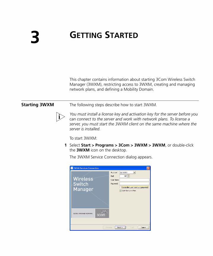
Starting 3WXM The following steps describe how to start 3WXM.
You must install a license key and activation key for the server before you can connect to the server and work with network plans. To license a server, you must start the 3WXM client on the same machine where the server is installed.
To start 3WXM:
1 Select Start > Programs > 3Com > 3WXM > 3WXM, or double-click the 3WXM icon on the desktop.
The 3WXM Service Connection dialog appears.
50 CHAPTER 3: GETTING STARTED
2 In the 3WXM Services Connection dialog box, enter the IP address of the machine on which 3WXM Services is installed.
3 If you or the 3WXM administrator configured 3WXM access control, enter your username and password.
4 Click Next.
If the 3WXM Service is installed on the same machine as the one you are using to run 3WXM, use 127.0.0.1 as the IP address. This is a standard IP loopback address.
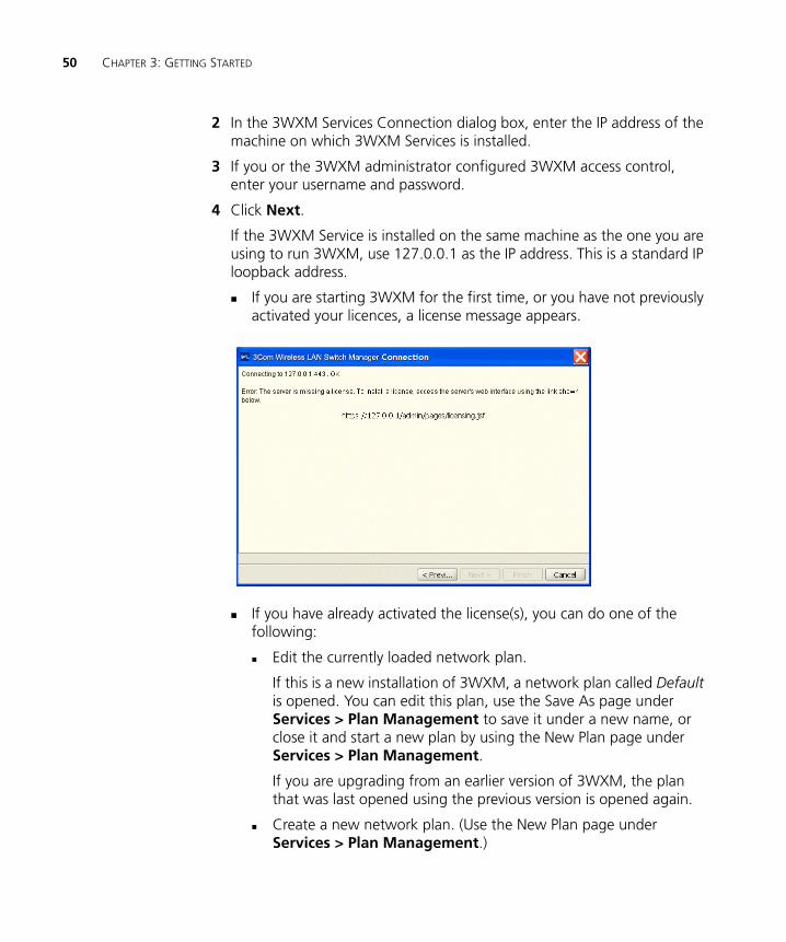
If you are starting 3WXM for the first time, or you have not previously activated your licences, a license message appears.
If you have already activated the license(s), you can do one of the following:
Edit the currently loaded network plan.
If this is a new installation of 3WXM, a network plan called Default is opened. You can edit this plan, use the Save As page under Services > Plan Management to save it under a new name, or close it and start a new plan by using the New Plan page under Services > Plan Management.
If you are upgrading from an earlier version of 3WXM, the plan that was last opened using the previous version is opened again.
Create a new network plan. (Use the New Plan page under Services > Plan Management.)
Starting 3WXM 51
Switch to an existing network plan. Open one of the sample plans included with 3WXM or a plan that you or another 3WXM user has saved on the 3WXM Services host.
To open an existing network plan, use the Switch Plan page under Services > Plan Management and select the network plan from the list of available network plans. 3WXM connects to the 3WXM Services host and opens the specified network plan on the server. See “Managing Network Plans” on page 59 for more information.
3WXM has two sample plans:
QuickStart—Contains a two-floor building with two WX switches and two MAP access points on each switch. Each switch and its MAPs provide coverage for a floor. The equipment is configured to provide both clear (unencrypted) and secure (802.1X) wireless access. (For more information, see the Wireless LAN Switch and Controller Quick Start Guide.)
StarterKit—Contains a simple rectangle as a floor plan, but with one WX switch and four MAP access points.
3WXM saves the Default plan even if you switch network plans or close it.
(For more information, see “Working with Network Plans” on page 57.)
If a Certificate Check dialog appears, click Accept.
If this is the first time you are starting 3WXM, or you have not yet activated your license, the client will not establish a connection to the server when you click Next. Instead, the client will briefly contact the server, then display the following message: Missing license.
If you need to install license information, click Cancel to close the dialog and go to step 5.
If you have already installed license information, go to step 17.
5 Select Help > Licensing from the tool bar. The License Wizard is displayed.
52 CHAPTER 3: GETTING STARTED
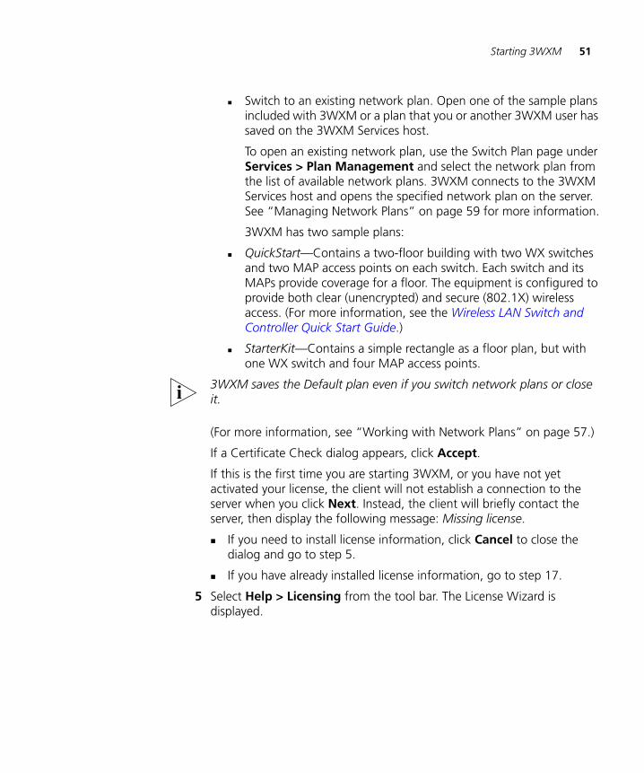
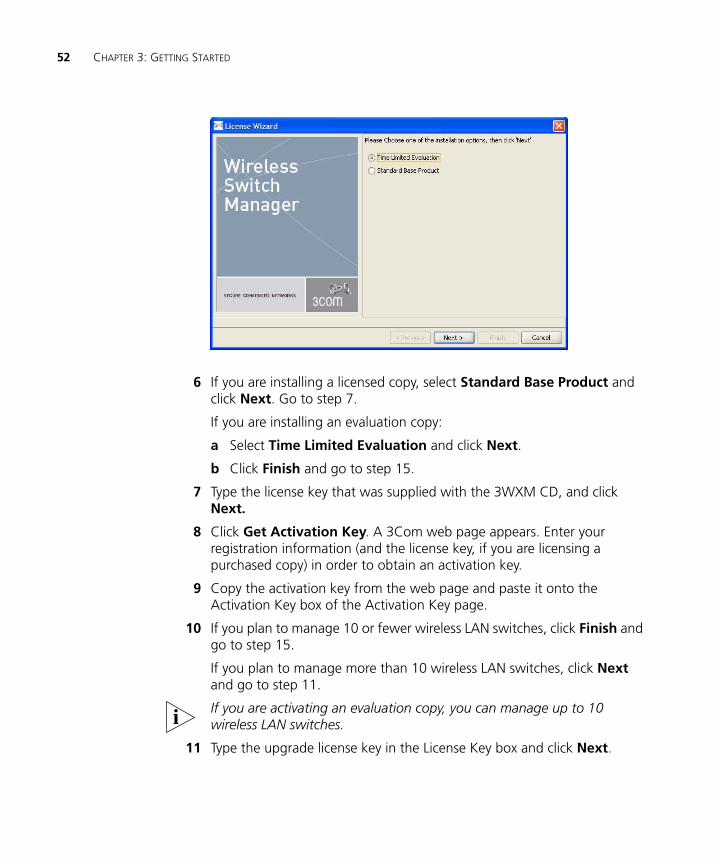
6 If you are installing a licensed copy, select Standard Base Product and click Next. Go to step 7.
If you are installing an evaluation copy:
a Select Time Limited Evaluation and click Next.
b Click Finish and go to step 15.
7 Type the license key that was supplied with the 3WXM CD, and click Next.
8 Click Get Activation Key. A 3Com web page appears. Enter your registration information (and the license key, if you are licensing a purchased copy) in order to obtain an activation key.
9 Copy the activation key from the web page and paste it onto the Activation Key box of the Activation Key page.
10 If you plan to manage 10 or fewer wireless LAN switches, click Finish and go to step 15.
If you plan to manage more than 10 wireless LAN switches, click Next and go to step 11.
If you are activating an evaluation copy, you can manage up to 10 wireless LAN switches.
11 Type the upgrade license key in the License Key box and click Next.
Starting 3WXM 53
12 Click the Get Activation Key to access the product activation key for your upgrade license. Register your upgrade license in order to obtain its activation key.
13 Copy the activation key for the upgrade license from the web page and paste it into the Activation Key box of the Activation Key page.
14 Click Finish.
15 To connect to the server, select File > Connect from the menu bar. The 3WXM Services Connection dialog box appears.
16 In the 3WXM Services Connection dialog box, enter the IP address of a host running 3WXM Services (leave this as 127.0.0.1 if the services are being run on this host), and then click Next.
17 After a connection is established to the specified 3WXM Services host, do one of the following:
Edit the currently loaded network plan. The first time you start 3WXM, a network plan called Default is opened.
Create a new network plan.
If you select this option, wizard pages guide you in setting up a network plan. For more information, see “Creating a Network Plan” on page 58.
Switch to an existing network plan. You can open the sample plan included with 3WXM or a plan that you or another 3WXM user has saved on the 3WXM Services host.
54 CHAPTER 3: GETTING STARTED
Restricting Access to 3WXM
By default, all users who have been successfully authenticated to a system with 3WXM installed on it can run 3WXM. You can restrict the users allowed to access 3WXM on a system and define their access privileges by creating three types of 3WXM user accounts:
Administrator—This account can monitor the network, configure the network, and administer 3WXM. When creating an administrator account, you must assign an administrator password, which you are required to provide the next time you configure access privileges. This account also can remove locks.
Provisioning User—This account can configure and monitor the network. However:
The Plan Management options are unavailable.
All configuration options in the 3WXM Services Setup dialog box are unavailable.
Monitor User—This account can only monitor the network. When users with a monitor account open a network plan, they can see configuration changes that have been deployed to the network. Any configuration changes that have not been deployed are not visible.
On the Tools menu, the Certificates option is greyed out.
All tasks for creating configuration items are greyed out.
All configuration options in the 3WXM Services Setup page are greyed out.
Options to deploy and undo local changes and accept or undo network changes are not available.
The options on the right-click menu in the Organizer panel are greyed out.
Configuration items that are related specifically to monitoring (logs, managed devices, site surveys and work orders) can be configured. However, new network plans cannot be configured.
The 3WXM user accounts you create must also exist in the Windows domain or local operating system. Otherwise, those users cannot start 3WXM.
Restricting Access to 3WXM 55
Creating anAdministrator
Account
Before you can restrict user access to 3WXM, you must create an administrator account. After creating an administrator account, you can create provision or monitor accounts.
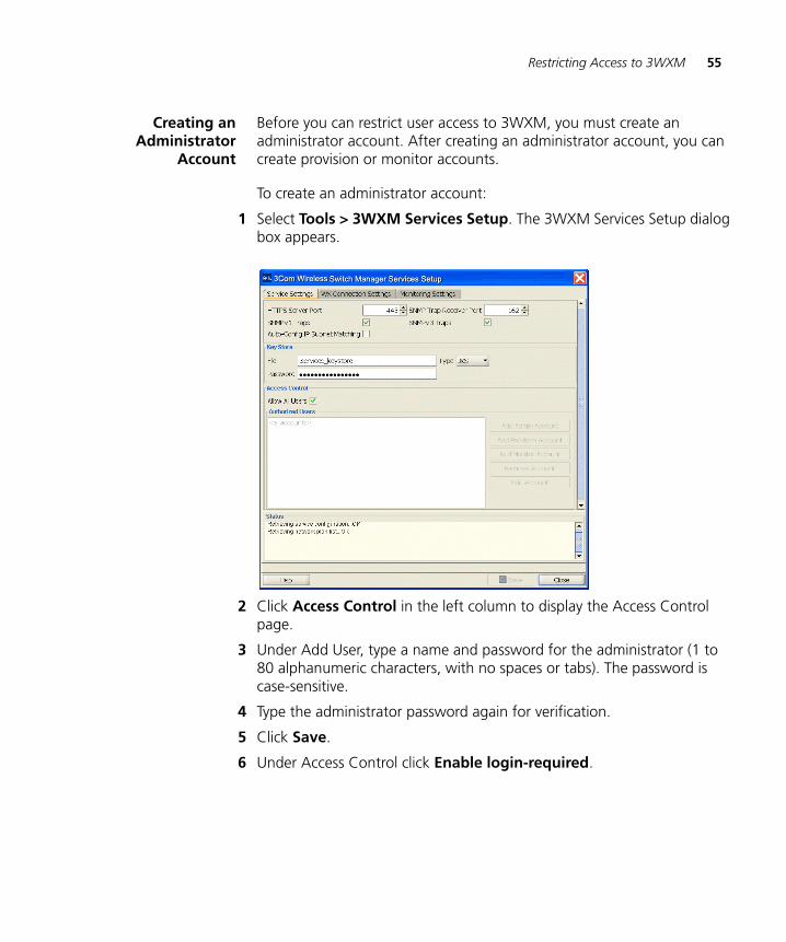
To create an administrator account:
1 Select Tools > 3WXM Services Setup. The 3WXM Services Setup dialog box appears.
2 Click Access Control in the left column to display the Access Control page.
3 Under Add User, type a name and password for the administrator (1 to 80 alphanumeric characters, with no spaces or tabs). The password is case-sensitive.
4 Type the administrator password again for verification.
5 Click Save.
6 Under Access Control click Enable login-required.
56 CHAPTER 3: GETTING STARTED
Creating Provision orMonitor Accounts
After creating an administrator account, you can create provision or monitor accounts. To create a provision or monitor account:
1 Select Services > Setup to access the 3WXM Services Setup page.
2 Click Access Control in the left column to display the Access Control page.
3 Under Add User, type a name for the user.
4 From the Role box, select Provisioning User or Monitoring User.
5 Type the password for the user (1 to 80 alphanumeric characters, with no spaces or tabs). The password is case-sensitive.
6 Type the administrator password again for verification.
7 Click Save.
Deleting 3WXM UserAccounts
To delete a 3WXM user account:
1 Select Services > Setup to access the 3WXM Services Setup page.
2 Click Access Control in the left column to display the Access Control page.
3 Under Authorized Users, click Delete next to the user you want to delete.
Disabling AccessControl
If you have enabled access control for 3WXM, you can disable access control. This allows all users who have successfully authenticated to the system on which 3WXM is installed to run 3WXM.
To disable access control:
1 Select Services > Setup to access the 3WXM Services Setup page.
2 Click Access Control in the left column to display the Access Control page.
3 Under Access Control, click Allow all users.
4 WORKING WITH NETWORK PLANS
A network plan is the workspace in 3WXM you use to design a 3Com network. In a network plan, you define components of the network (WX switches, MAP access points, and optional third-party access points). Regardless of whether you intend to use physical planning features, you must create a network plan before you can configure or manage WX switches or monitor network data.
A network plan allows modular management of large networks based on organizational or geographical boundaries. For example, a network plan can represent a campuswide network. You also can define a physical representation of the network (sites, buildings, and floors). In this case, you can import drawings of your floor plans into the network plan or draw plan details manually. You can then identify the RF characteristics by importing data from a site survey or by manually identifying RF objects.
3Com recommends that you limit a network plan to a single campus or Mobility Domain (3Com network domain).
Different countries have different regulatory limits for 802.11 radios. Setting the country code in the network plan automatically enforces the appropriate regulatory limits for all configured radios. The greatest geographical scope for a network plan is a country, because a network plan is based on one specific country code.
58 CHAPTER 4: WORKING WITH NETWORK PLANS
Creating a Network Plan
To create a network plan:
1 Select Services > Plan Management to access the 3WXM Plan Management page.
2 Click New Plan in the left column to display the New Plan page.
3 In the Network Plan Name box, type a name for the network plan. You can use 1 to 60 alphanumeric characters, with no spaces, tabs, or any of the following: slash (/), backslash (\), quotation marks (“ ”), asterisk (*), question mark (?), angle brackets (< >), or vertical bar (|).
4 In the Country Code list, select the country where the network is to be deployed.
You must select a country code before continuing. The country code you select here is the default for all MAPs in the network plan. However, you can override the country code in individual sites within the network plan.
5 Click the box next to Open this Plan to open the plan in 3WXM after it is created.
6 Click Create to save the network plan on the server.
The network plan settings appear in the Content panel and the following links appear in the Task List panel:
Mobility Domain—Configure a named set of WX switches that support user roaming. (See “Creating a Mobility Domain” on page 67.)
Wireless Switch—Use a wizard to configure basic switch parameters. (See “Using the Create Wireless Switch Wizard” on page 173.)
Third-Party AP—Add a third-party AP for use in network planning. (See “Creating a Third-Party AP” on page 68.)
Country Code—Change the regulatory domain for the MAPs in the network plan. (See “Changing the Country Code” on page 70.)
Disable Auto-Tune—Update the channel and power information in the network plan to match the channel and power settings assigned to MAPs in the network by the RF Auto-Tune feature. (See “Applying the RF Auto-Tuning Settings of a Network Plan to the Network Plan” on page 70.)
Managing Network Plans 59
Upload Wireless Switch—Add a WX switch that is already deployed in the live network to the network plan. (See “Uploading a WX Switch into the Network Plan” on page 71.)
Convert Auto APs—Convert MAPs that were configured by an Auto-AP profile into statically configured MAPs. (See “Converting Auto DAPs into Statically Configured APs” on page 72.)
Remove Auto DAPs—Remove Auto DAPs from the network plan entirely.
Network Domain—Configure a group of Mobility Domains into a single Network Domain. (See “Creating a WX Switch” on page 68.)
Managing Network Plans
After creating a network plan, you can save, close, open, or delete it. You can also share a network plan with others.
Saving a NetworkPlan
When you create a network plan and save changes, a directory with the same name as the network plan is created in the config-db directory of the 3WXM installation directory on the 3WXM Services host.
Each time you save a configuration change, 3WXM saves the changes to the network plan. You do not need to explicitly save the network plan itself. However, if the network plan has unsaved changes when you select to exit 3WXM or close a network plan, 3WXM displays a prompt to ask whether you want to save or discard the changes, or cancel the request. (See “Saving or Discarding Configuration Changes” on page 36.)
3Com recommends that you regularly back up the config-db directory so that you have additional copies of your network plans.
(In addition to this section, see “Managing Network Plans” on page 513.)
If the plan has unsaved changes and 3WXM Services becomes unavailable before the changes are saved, 3WXM Client buffers the changes until 3WXM Services becomes available again. However, for the changes to be buffered, you must leave your 3WXM Client session open and leave the network plan open.
60 CHAPTER 4: WORKING WITH NETWORK PLANS
Saving a Network Plan with a New Name
You can save a network plan with a new name by using the Save As feature.
To save a network plan with a new name:
1 Select Services > Plan Management to access the 3WXM Plan Management page.
2 Click Save As in the left column to display the Save As Network Plan page.
3 In the Network Plan Name box, type a name for the network plan. You can use 1 to 60 alphanumeric characters, with no spaces, tabs, or any of the following: slash (/), backslash (\), quotation marks (“ ”), asterisk (*), question mark (?), angle brackets (< >), or vertical bar (|).
To place the name of an existing plan into the Network Plan Name, click the button next to the name of the network plan, and then click Select.
4 Click Save to save the network plan with the new name.
Opening a NetworkPlan
Network plans reside on a host running 3WXM Services. You can open an existing network plan by connecting to the 3WXM Services host where the plan resides, selecting Services > Plan Management, then specifying the name of the plan in the dialog. The network plan is then opened in the 3WXM main window.
You can open a network plan created in a previous version of 3WXM with a later version of 3WXM. For example, if you created a network plan in 3WXM Version 4.0, you can open the plan in 3WXM Version 4.1. However, because a network plan created in 3WXM Version 4.0 manages WX switches running MSS Version 4.0, you cannot use new features available in MSS Version 4.1 unless you upgrade the WX switches to MSS Version 4.1. (To upgrade WX switches, see “Distributing System Images” on page 369.)
To open a network plan:
1 Establish a connection to the 3WXM Services host on which the network plan is saved.
2 You can do this by restarting 3WXM or selecting File > Connect, and then entering the IP address of the 3WXM Services host in the 3WXM Services Connection dialog box.
3 After the connection is established with the 3WXM Services host, select Services > Plan Management to access the 3WXM Plan Management page.
Managing Network Plans 61
4 Click Switch Plan in the left column to display a list of available network plans.
5 Select the network plan you want to open and click Switch.
If any changes were made to the currently loaded network plan, you are prompted to save them and close the file. The Switch Network Plan dialog box appears.
3WXM establishes a new connection to the host running 3WXM Services and loads the specified network plan.
Importing a NetworkPlan
You can import objects from another network plan into the currently open plan. When you import objects from another plan, objects are added to the currently open plan as follows:
If an object (object name) exists in the plan you are importing but not in the open plan, the object is added to the open plan.
If an object (object name) exists in both plans, the copy of the object in the imported plan replaces the object in the open plan.
If both plans have the same floor name, the floor in the plan you are importing completely replaces the floor of the same name in the other plan.
3Com recommends that you save a backup copy of the plan before importing objects from another plan. To save a backup copy, you can use the Save As page.
To import a plan:
1 Select Services > Plan Management to access the 3WXM Plan Management page.
2 Click Import Plan in the left column to display the Import Plan page.
3 Select the network plan you want to import, from the Plan drop-down list.
4 3WXM compares the object names in the plan to be imported with the object names in the open plan. If both plans have objects of the same name and type, the objects are listed and Conflict appears in the Status column.
5 Do one of the following, depending on whether you want to import all objects from the plan:
62 CHAPTER 4: WORKING WITH NETWORK PLANS
If you do not want to replace the objects in the open plan with their like-named objects in the other plan, click Cancel. 3WXM does not import any objects from the plan.
If you do want to replace the objects, click Import. 3WXM imports the objects into the open plan.
Closing a NetworkPlan
You can close a network plan at any time. If you have unsaved changes, you are asked whether you want to save the changes.
To close a network plan:
1 In the main 3WXM window, select File > Close or File > Exit.
If the network plan has no unsaved changes, the network plan is closed. Otherwise, go to the next step.
2 If there are unsaved changes, 3WXM displays a dialog asking whether you want to save the changes, discard them, or cancel the request to close the plan or exit the application. Do one of the following:
Select Apply to save the changes and close the plan.
Select Discard to close the plan without saving the changes.
Select Cancel to cancel the request to close the plan or exit the application, and continue working with the plan.
Deleting a NetworkPlan
You can delete a network plan at any time.
CAUTION: The Delete Network Plan wizard has a Cancel button, but this button does not cancel deletion of a network plan. 3WXM deletes the plan as soon as you click Next.
You cannot delete the currently active plan. To delete the active plan, first use the Switch Plan page to select another plan to be active, then delete the plan.
To delete a network plan
1 Select Services > Plan Management to access the 3WXM Plan Management page.
2 Click Delete Plans in the left column to display the Delete Plans page.
3 Select one or more the network plans from the list.
4 Click Delete. The network plan is deleted.
Managing Network Plans 63
Sharing a NetworkPlan
Since the 3WXM plan repository resides on a networked server (the host running 3WXM Services), you can easily share access to network plans among hosts running the 3WXM Client.
When you make changes to a network plan, 3WXM locks the part of the plan you are modifying. Other 3WXM Clients can still open the network plan, but the lock prevents the other clients from modifying the part of the plan you are already modifying. The lock remains in effect until your modification is saved. 3WXM then removes the lock.
When a user with an administrator or provision account tries to access a part of a plan that is already locked by another user, 3WXM displays the Lock Info page. The Lock Info page indicates who has locked the network plan. You can optionally override the user’s lock. Note that only a user with Administrator privileges can override another user’s lock.
To override another user’s lock
1 Select Services > Lock Management to access the 3WXM Lock Information page.
2 A list of objects that have been locked appears.
3 Select the object whose lock you want to delete and click Delete. (Only an Administrator can delete a lock.)
4 A message is displayed indicating that the user whose lock you selected will not be able to save their changes when you delete their lock. Click Yes to confirm that you want to do this.
If you override the lock, 3WXM unlocks the part of the plan that was locked, and notifies the other 3WXM users about the lock change. From this point on, the former lock holder cannot save changes to the previously locked portion of the plan.
By default, 3WXM sends a message to all users who have the plan open with monitor access to inform them when changes are saved to the plan. In addition, 3WXM sends a message to each monitor user, so that one of them can then edit the plan.
To disable notification
1 In the main 3WXM window, select Tools > Preferences.
2 Click the Persistence tab.
3 To disable change notification, clear Plan Change Notification.
4 Click Close.
64 CHAPTER 4: WORKING WITH NETWORK PLANS
Defining a Mobility Domain
A Mobility Domain is a collection of WX switches that work together to support roaming users. One of the WX switches is defined as a seed device, which distributes information to the other WX switches defined in the Mobility Domain.
A Mobility Domain allows users to roam geographically from one WX switch to another without losing network connectivity. Users connect as a member of a VLAN through their authorized identities. If the native VLAN for a user is not present on the WX to which the user connects, the WX creates a tunnel to that VLAN.
A network plan can contain more than one Mobility Domain. Standalone WX switches and third-party APs do not need to be configured within a Mobility Domain.
You use 3WXM to create a Mobility Domain and define its seed device and the other WX switches in the Mobility Domain. If you already have WX switches installed and configured, you can upload the configurations of the switches to 3WXM to have them included in a Mobility Domain.
Roaming Behavior For a client session to be considered a roaming session (and not a new session), the following criteria must be met:
The client associates or reassociates with a MAP in the Mobility Domain, and the client already has a session on a different MAP in the Mobility Domain. The existing session can be in one of two states:
Active—The normal state for a client that has left radio range without sending a request to disassociate.
Diassociated—The state of a client that has sent an 802.11 disassociate frame, but has not roamed or aged out yet.
Mobility Domain communications are stable. Generally, the communications required for roaming are the same as those required for VLAN tunneling. Roaming between ports on a WX is possible even if the Mobility Domain is down.
Authentication, authorization, and accounting (AAA) on the MAP to which the client roams is successful on the first attempt. An authentication or authorization failure clears the client session. Depending on when the failure occurs, roaming can be disqualified or delayed.
Defining a Mobility Domain 65
The client uses the same authorization parameters for the new session as for the old session. For example, changing the Encryption-Type or VLAN-Name parameter might cause a new session to be recorded, rather than a roam within the same session.
A disassociated session has a grace period of 5 seconds in which the session history can be retrieved and forwarded. After 5 seconds, the session is cleared, and its accounting is stopped. You cannot configure the grace period.
If the client MAC address in a Mobility Domain is not found in 5 seconds, the session is considered new.
The 802.1X reauthentication timeout has little impact on roaming. If the timeout lapses, 802.1X processing is performed on the existing association. Accounting and roaming history are not affected if the reauthentication is successful, because the client is still associated with the same MAP. If reauthentication fails, the session is cleared, and it is not eligible for roaming. If the client associates to the same MAP, that is recorded as a new session.
Roaming creates the following effects:
Remote Authentication Dial-In User Service (RADIUS) accounting is treated as a continuation of an existing session, rather than a new one.
You can view roaming history in the Monitor tab. See “Monitoring the Network” on page 437.
The old session is cleared from the WX, even if the client did not explicitly disassociate from the MAP and the 802.1X reauthentication interval has not lapsed.
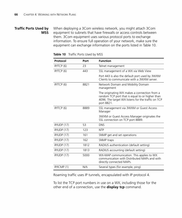
66 CHAPTER 4: WORKING WITH NETWORK PLANS
Traffic Ports Used byMSS
When deploying a 3Com wireless network, you might attach 3Com equipment to subnets that have firewalls or access controls between them. 3Com equipment uses various protocol ports to exchange information. To ensure full operation of your network, make sure the equipment can exchange information on the ports listed in Table 10.
Roaming traffic uses IP tunnels, encapsulated with IP protocol 4.
To list the TCP port numbers in use on a WX, including those for the other end of a connection, use the display tcp command.
Table 10 Traffic Ports Used by MSS
Protocol Port Function
IP/TCP (6) 23 Telnet management
IP/TCP (6) 443 SSL management of a WX via Web View
Port 443 is also the default port used by 3WXM Clients to communicate with a 3WXM server.
IP/TCP (6) 8821 Network Domain and Mobility Domain management
The originating WX makes a connection from a random TCP port that is equal to or higher than 4096. The target WX listens for the traffic on TCP port 8821.
IP/TCP (6) 8889 SSL management via 3WXM or Guest Access Manager
3WXM or Guest Access Manager originates the SSL connection on TCP port 8889.
IP/UDP (17) 53 DNS
IP/UDP (17) 123 NTP
IP/UDP (17) 161 SNMP get and set operations
IP/UDP (17) 162 SNMP traps
IP/UDP (17) 1812 RADIUS authentication (default setting)
IP/UDP (17) 1813 RADIUS accounting (default setting)
IP/UDP (17) 5000 WX-MAP communication. This applies to WX communication with Distributed MAPs and with directly connected MAPs.
IP/ICMP (1) N/A Several types (for example, ping)
Defining a Mobility Domain 67
Creating a MobilityDomain
The Create Mobility Domain wizard requires you to select the switches to place in the Mobility Domain and to select the seed switch. Add the switches to the network plan before you configure the Mobility Domain.
1 Select the Configuration tool bar option.
2 Select the network plan in the Organizer panel.
3 Select the Mobility Domain task in the Task List panel. The Create Mobility Domain wizard appears.
4 In the Name box, type the name for the Mobility Domain (1 to 16 characters, with no spaces or tabs).
5 Click Next.
6 In the Available Devices list, select the WX switches you want to add to the Mobility Domain.
7 Click Next.
8 Select the switch to act as the seed switch for the Mobility Domain.
9 Click Finish.
Enabling WX-WXSecurity
You can enable secure management communication among the WX switches in a Mobility Domain. By default, WX-WX security is disabled.
1 Select the Configuration tool bar option.
2 Select the Mobility Domain in the Organizer panel.
3 In the Task List panel, select WX-WX Security. A configuration wizard appears.
4 Select Required from the Security Mode drop-down list and click Next.
5 Enter a 16-byte hexadecimal fingerprint in the Seed Public Key box. The fingerprint will be used to generate a key the WX switches in the Mobility Domain will use to authenticate management traffic among themselves.
Use a colon between each byte. Here is an example:00:11:22:33:44:55:66:77:88:99:aa:bb:cc:dd:ee:ff
6 Click Finish.
68 CHAPTER 4: WORKING WITH NETWORK PLANS
Creating a WX Switch
To create a WX switch:
1 Select the Configuration tool bar option.
2 In the Organizer panel, select the network plan name.
3 In the Task List panel, select Wireless Switch.
4 Go to “Using the Create Wireless Switch Wizard” on page 173.
Creating a Third-Party AP
You can add a third-party AP to the equipment list of the network plan.
When you use RF Planning, you can place the AP on its location on a floor plan. In this case, 3WXM takes the channel number of the AP into account when assigning channels to MAPs.
1 Select the Configuration tool bar option.
2 Select the network plan in the Organizer panel.
3 Select the Third Party AP task in the Task List panel. The Create Third Party AP wizard appears.
4 In the Name box, type a name for the access point. You can use 1 to 32 characters, with no punctuation except the following: period (.), hyphen (-), or underscore (_).
5 Optionally, in the Manufacturer ID box, type the manufacturer identification for the access point (1 to 30 characters, with no spaces).
6 In the Product ID box, type the product identification for the access point (1 to 30 characters, with no spaces).
7 In the IP Address box, type the IP address for the access point.
If you specify an IP address, you can use Telnet and a Web browser with this access point.
8 In the Telnet Port Number box, specify the port number for Telnet service.
9 In the HTTP Port Number box, specify the port number for HTTP service.
10 Click Next.
11 In the AP Model drop-down list, select one of the following:
AP (Dual Radio)—802.11a and 802.11b or 802.11b/g
AP (Single Radio)—802.11a, 802.11b, or 802.11g
Creating a Third-Party AP 69
12 In the Radio Type drop-down list, select one of the following: 11a, 11b, 11g.
The choices available depend on the selection you made in step 11.
13 Click Next.
14 Verify the radio slot number and radio type.
For a dual-radio access point, 802.11b/g radios have a slot number of 1. 802.11a radios have a slot number of 2.
15 In the Channel Number list, select the channel number for the radio.
16 In the Transmit Power box, specify the transmit power for the radio.
17 To enable the radio, select Enabled.
The radio for the access point must be enabled to be considered in channel allocation.
18 In the SSID box, type the service set identifier (SSID) for the radio.
19 In the MAC Address box, type the MAC address of the radio.
20 In the Antenna Gain list, select the antenna gain for the radio.
21 If the access point has only one radio, click Finish. Otherwise, go to step 22.
22 Click Next. The Radio A page appears.
23 Repeat step 14 through step 20 for the 802.11a radio.
24 Click Finish to save the changes.
25 To place the AP on a floor plan, see “Moving a Third-Party AP Icon to its Floor Location” on page 138.
70 CHAPTER 4: WORKING WITH NETWORK PLANS
Changing the Country Code
The country code determines the valid radio types as well as channel numbers and power settings for MAP radios. The country code is one of the parameters you set when you create a network plan. If you need to change the country code of a plan, use the following procedure.
1 Select the Configuration tool bar option.
2 In the Organizer panel, select the network plan name.
3 In the Task List panel, select Country Code. The Change Country Code wizard appears.
4 Select the country code from the drop-down list.
5 Click Next.
3WXM changes the country code on all the WX switches in the network plan, and lists its progress as it does so.
6 Click Finish.
Applying the RF Auto-Tuning Settings of a Network Plan to the Network Plan
If RF Auto-Tuning is running on MAP radios in the network, you can update the radios in the network plan with the channel and power settings currently in effect on the same radios in the network. You also can lock down the channel and power settings in the plan and in the network by disabling RF Auto-Tuning on the radios.
RF Auto-Tuning settings are applied only to configured MAPs, not to Auto DAPs (Distributed MAPs configured using a Distributed MAP profile).
This option also disables RF Auto-Tuning on the radios. When RF Auto-Tuning is disabled, the channel and power settings on the radios are static.
To apply the RF Auto-Tuning settings to the network plan:
1 Select the Configuration tool bar option.
2 In the Organizer panel, select the network plan name.
3 In the Task List panel, select Disable Auto-Tune. The Disable Auto-Tune wizard appears.
4 Select the RF Auto-Tuning settings you want to apply. Both channel and power settings are selected by default.
Uploading a WX Switch into the Network Plan 71
5 Select the scope:
Mobility Domain
WX switch
Radio profile
Individual MAP radio
To select a radio profile, display it first by clicking on the plus sign next to the WX switch. To select an individual radio, display it first by displaying its radio profile, then clicking on the plus sign next to the radio profile.
6 If you accessed the wizard from the toolbar, select the scope. You can select a Mobility Domain, WX switch, MAP, or radio profile.
7 Click Next. The progress is displayed.
8 Click Finish.
Uploading a WX Switch into the Network Plan
To upload a WX switch into a network plan:
1 Select the Configuration tool bar option.
2 In the Task List panel, select Upload WX.
3 In the IP Address box, type the IP address for the WX switch.
4 In the Enable Password box, type the enable password for the WX switch.
This password must match the enable password that was defined using the CLI command set enablepass. For more information, see the Wireless LAN Switch and Controller Configuration Guide.
5 Click Next. The uploading progress is shown.
6 After the Successfully uploaded device message is displayed, click Next.
3WXM uses its verification rules to check the configuration of the switch. If an item in the configuration generates an error or warning, 3WXM displays the error or warning message.
7 Review the verification messages to determine whether you will need to make changes to the configuration of the switch after uploading it into 3WXM.
8 Click Next.
9 Click Finish.
72 CHAPTER 4: WORKING WITH NETWORK PLANS
10 If 3WXM displayed error or warning messages, select the Verification tool bar option and go to “Verifying Configuration Changes” on page 377.
Converting Auto DAPs into Statically Configured APs
Distributed MAPs that are not configured on any WX switches in the Mobility Domain can nonetheless be booted and managed by a switch if the switch has a profile for Distributed MAPs, and has capacity to manage the MAP. A MAP that is booted and managed using a Distributed MAP profile is here called an Auto DAP.
You can convert the temporary connection of an Auto DAP to a WX switch into a permanent, statically configured connection on the switch.
1 Select the Configuration tool bar option.
2 In the Organizer panel, select the WX switch.
3 In the Task List panel, select Convert Auto DAPs.
The Convert Auto DAPs wizard appears. The MAPs that were configured using a Distribute MAP template are listed.
4 Select the MAPs you want to convert into statically configured MAPs.
5 Click Next.
6 Select the temporary connections you want to convert into static connections.
7 Click Finish.
Creating a Network Domain
MSS Version 4.1 and higher allows functionality found in Mobility Domains to be extended over a multiple-site installation, in a Network Domain. A Network Domain is a group of geographically dispersed Mobility Domains that share information over a WAN link. This shared information allows a user configured in one Mobility Domain to establish connectivity on a WX switch in a remote Mobility Domain. The WX switch forwards the user traffic by creating a VLAN tunnel to a WX switch in the remote Mobility Domain.
In a Network Domain, one or more WX switches acts as a seed device. A Network Domain seed stores information about all of the VLANs on the Network Domain members. The Network Domain seeds share this information among themselves, so that every seed has an identical database.
(For more information, see the “Configuring Network Domains” chapter of the Wireless LAN Switch and Controller Configuration Guide.)
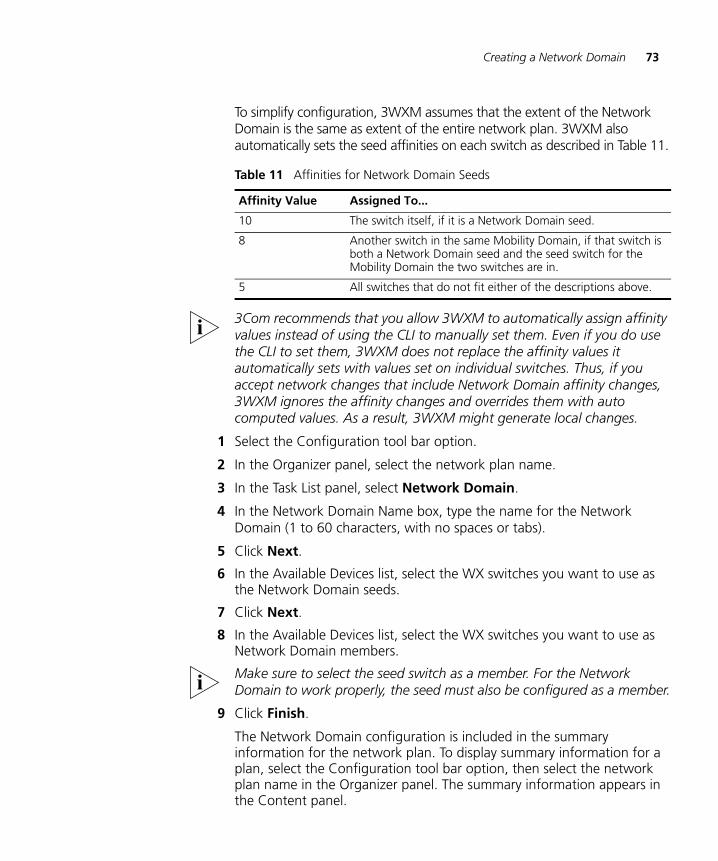
Creating a Network Domain 73
To simplify configuration, 3WXM assumes that the extent of the Network Domain is the same as extent of the entire network plan. 3WXM also automatically sets the seed affinities on each switch as described in Table 11.
3Com recommends that you allow 3WXM to automatically assign affinity values instead of using the CLI to manually set them. Even if you do use the CLI to set them, 3WXM does not replace the affinity values it automatically sets with values set on individual switches. Thus, if you accept network changes that include Network Domain affinity changes, 3WXM ignores the affinity changes and overrides them with auto computed values. As a result, 3WXM might generate local changes.
1 Select the Configuration tool bar option.
2 In the Organizer panel, select the network plan name.
3 In the Task List panel, select Network Domain.
4 In the Network Domain Name box, type the name for the Network Domain (1 to 60 characters, with no spaces or tabs).
5 Click Next.
6 In the Available Devices list, select the WX switches you want to use as the Network Domain seeds.
7 Click Next.
8 In the Available Devices list, select the WX switches you want to use as Network Domain members.
Make sure to select the seed switch as a member. For the Network Domain to work properly, the seed must also be configured as a member.
9 Click Finish.
The Network Domain configuration is included in the summary information for the network plan. To display summary information for a plan, select the Configuration tool bar option, then select the network plan name in the Organizer panel. The summary information appears in the Content panel.
Table 11 Affinities for Network Domain Seeds
Affinity Value Assigned To...
10 The switch itself, if it is a Network Domain seed.
8 Another switch in the same Mobility Domain, if that switch is both a Network Domain seed and the seed switch for the Mobility Domain the two switches are in.
5 All switches that do not fit either of the descriptions above.

74 CHAPTER 4: WORKING WITH NETWORK PLANS
5 PLANNING THE 3COM MOBILITY SYSTEM
The 3Com Wireless Switch Manager (3WXM) planning tools help you plan your mobility system. This chapter discusses the Building wizard and describes how to create a site, create or modify buildings, import or draw floor details, specify the RF characteristics of a floor, define a wireless coverage area, compute MAP placement, and generate RF network design information.
RF Planning Overview
The 3WXM planning tools calculate the 3Com equipment you need, how to configure it, and where to install it, all based on the information you provide about your wireless coverage needs.
You can display projected coverage, and even experiment with network changes. You can also optimize the plan based on RF measurements from the live network.
In addition, when you add the geographical information about your network to 3WXM, you can use 3WXM to visually find network clients or rogue devices.
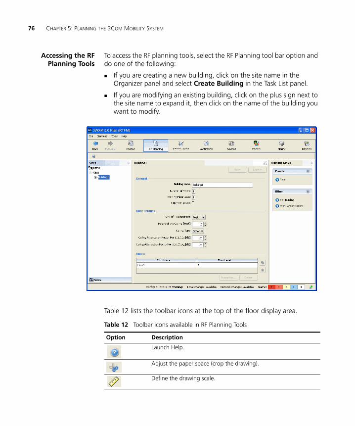
76 CHAPTER 5: PLANNING THE 3COM MOBILITY SYSTEM
Accessing the RFPlanning Tools
To access the RF planning tools, select the RF Planning tool bar option and do one of the following:
If you are creating a new building, click on the site name in the Organizer panel and select Create Building in the Task List panel.
If you are modifying an existing building, click on the plus sign next to the site name to expand it, then click on the name of the building you want to modify.
Table 12 lists the toolbar icons at the top of the floor display area.
Table 12 Toolbar icons available in RF Planning Tools
Option Description
Launch Help.
Adjust the paper space (crop the drawing).
Define the drawing scale.
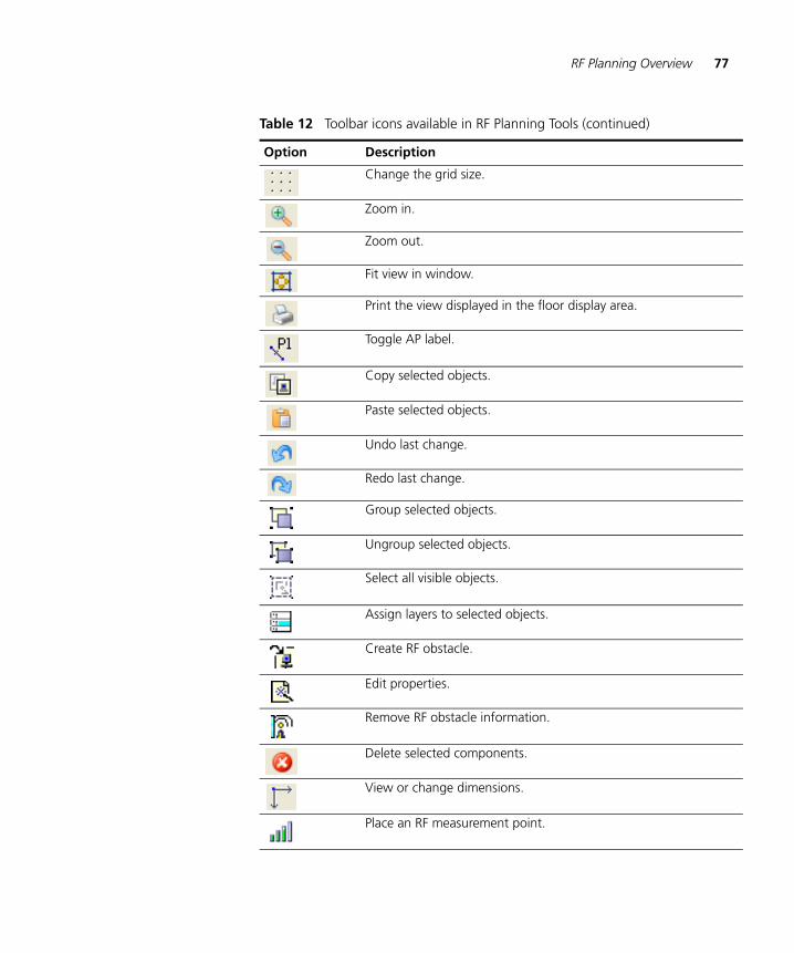
RF Planning Overview 77
Change the grid size.
Zoom in.
Zoom out.
Fit view in window.
Print the view displayed in the floor display area.
Toggle AP label.
Copy selected objects.
Paste selected objects.
Undo last change.
Redo last change.
Group selected objects.
Ungroup selected objects.
Select all visible objects.
Assign layers to selected objects.
Create RF obstacle.
Edit properties.
Remove RF obstacle information.
Delete selected components.
View or change dimensions.
Place an RF measurement point.
Table 12 Toolbar icons available in RF Planning Tools (continued)
Option Description
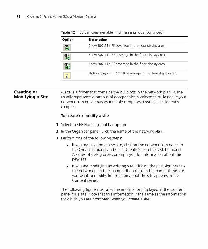
78 CHAPTER 5: PLANNING THE 3COM MOBILITY SYSTEM
Creating or Modifying a Site
A site is a folder that contains the buildings in the network plan. A site usually represents a campus of geographically colocated buildings. If your network plan encompasses multiple campuses, create a site for each campus.
To create or modify a site
1 Select the RF Planning tool bar option.
2 In the Organizer panel, click the name of the network plan.
3 Perform one of the following steps:
If you are creating a new site, click on the network plan name in the Organizer panel and select Create Site in the Task List panel. A series of dialog boxes prompts you for information about the new site.
If you are modifying an existing site, click on the plus sign next to the network plan to expand it, then click on the name of the site you want to modify. Information about the site appears in the Content panel.
The following figure illustrates the information displayed in the Content panel for a site. Note that this information is the same as the information for which you are prompted when you create a site.
Show 802.11a RF coverage in the floor display area.
Show 802.11b RF coverage in the floor display area.
Show 802.11g RF coverage in the floor display area.
Hide display of 802.11 RF coverage in the floor display area.
Table 12 Toolbar icons available in RF Planning Tools (continued)
Option Description
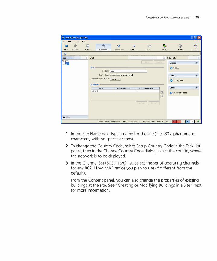
Creating or Modifying a Site 79
1 In the Site Name box, type a name for the site (1 to 80 alphanumeric characters, with no spaces or tabs).
2 To change the Country Code, select Setup Country Code in the Task List panel, then in the Change Country Code dialog, select the country where the network is to be deployed.
3 In the Channel Set (802.11b/g) list, select the set of operating channels for any 802.11b/g MAP radios you plan to use (if different from the default).
From the Content panel, you can also change the properties of existing buildings at the site. See “Creating or Modifying Buildings in a Site” next for more information.
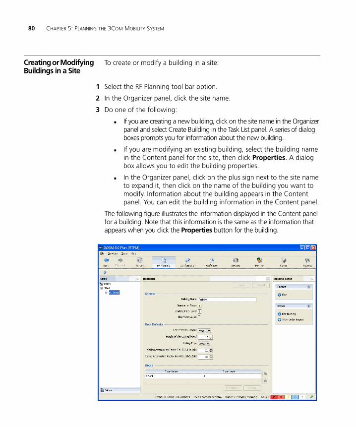
80 CHAPTER 5: PLANNING THE 3COM MOBILITY SYSTEM
Creating or Modifying Buildings in a Site
To create or modify a building in a site:
1 Select the RF Planning tool bar option.
2 In the Organizer panel, click the site name.
3 Do one of the following:
If you are creating a new building, click on the site name in the Organizer panel and select Create Building in the Task List panel. A series of dialog boxes prompts you for information about the new building.
If you are modifying an existing building, select the building name in the Content panel for the site, then click Properties. A dialog box allows you to edit the building properties.
In the Organizer panel, click on the plus sign next to the site name to expand it, then click on the name of the building you want to modify. Information about the building appears in the Content panel. You can edit the building information in the Content panel.
The following figure illustrates the information displayed in the Content panel for a building. Note that this information is the same as the information that appears when you click the Properties button for the building.
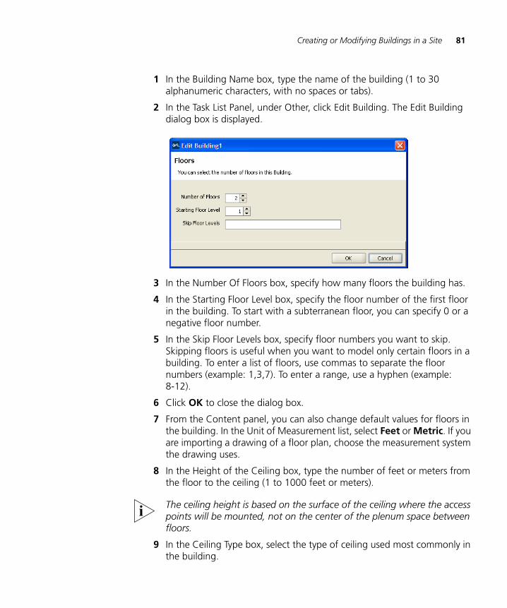
Creating or Modifying Buildings in a Site 81
1 In the Building Name box, type the name of the building (1 to 30 alphanumeric characters, with no spaces or tabs).
2 In the Task List Panel, under Other, click Edit Building. The Edit Building dialog box is displayed.
3 In the Number Of Floors box, specify how many floors the building has.
4 In the Starting Floor Level box, specify the floor number of the first floor in the building. To start with a subterranean floor, you can specify 0 or a negative floor number.
5 In the Skip Floor Levels box, specify floor numbers you want to skip. Skipping floors is useful when you want to model only certain floors in a building. To enter a list of floors, use commas to separate the floor numbers (example: 1,3,7). To enter a range, use a hyphen (example: 8-12).
6 Click OK to close the dialog box.
7 From the Content panel, you can also change default values for floors in the building. In the Unit of Measurement list, select Feet or Metric. If you are importing a drawing of a floor plan, choose the measurement system the drawing uses.
8 In the Height of the Ceiling box, type the number of feet or meters from the floor to the ceiling (1 to 1000 feet or meters).
The ceiling height is based on the surface of the ceiling where the access points will be mounted, not on the center of the plenum space between floors.
9 In the Ceiling Type box, select the type of ceiling used most commonly in the building.
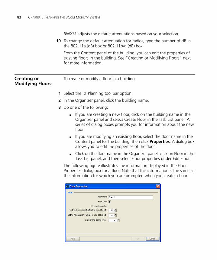
82 CHAPTER 5: PLANNING THE 3COM MOBILITY SYSTEM
3WXM adjusts the default attenuations based on your selection.
10 To change the default attenuation for radios, type the number of dB in the 802.11a (dB) box or 802.11b/g (dB) box.
From the Content panel of the building, you can edit the properties of existing floors in the building. See “Creating or Modifying Floors” next for more information.
Creating or Modifying Floors
To create or modify a floor in a building:
1 Select the RF Planning tool bar option.
2 In the Organizer panel, click the building name.
3 Do one of the following:
If you are creating a new floor, click on the building name in the Organizer panel and select Create Floor in the Task List panel. A series of dialog boxes prompts you for information about the new floor.
If you are modifying an existing floor, select the floor name in the Content panel for the building, then click Properties. A dialog box allows you to edit the properties of the floor.
Click on the floor name in the Organizer panel, click on Floor in the Task List panel, and then select Floor properties under Edit Floor.
The following figure illustrates the information displayed in the Floor Properties dialog box for a floor. Note that this information is the same as the information for which you are prompted when you create a floor.
Importing or Drawing Floor Details 83
4 To change the floor name, type the new name in the Floor Name box (1 to 60 alphanumeric characters, with no tabs). Each floor name in a building must be unique.
5 To change the default attenuation for radios, type the number of dB in the 802.11a (dB) box or 802.11b/g (dB) box.
6 In the Height of the Ceiling box, type the number of feet or meters from the floor to the ceiling (1 to 1000 feet or meters).
The ceiling height is based on the surface of the ceiling where the access points will be mounted, not on the center of the plenum space between floors.
7 Click OK.
After creating a floor, you can import or draw details about the floor. See “Importing or Drawing Floor Details” next for more information.
Importing or Drawing Floor Details
To add information for a floor, import a drawing of the floor or use the graphics tools in 3WXM to draw the floor.
After importing or drawing the floor, specify the RF characteristics of the floor, by specifying the attenuation of obstacles such as walls, doors, windows, and others. The attenuation of an object indicates how much the object affects an 802.11 radio signal. 3WXM uses the attenuation information when calculating how many MAPs you need and where to place them in order to provide the desired wireless coverage.
The following sections describe how to import or draw a floor. For information about specifying the RF characteristics of the floor, see “Specifying the RF Characteristics of a Floor” on page 100.
Importing a Drawingof a Floor
You can import a drawing of your floor plan into 3WXM. 3WXM supports the following file types:
AutoCAD drawing (DWG), a native binary format used by AutoCAD. You can import the following versions: R13, R14, R2000. Use R2000 if available.
Drawing Interchange Format (DXF), an ASCII-based interchange format used for multi-vendor interoperability. You can import the following versions: R12, R13, R14, R2000. Use R2000 if available.
Graphics Interchange Format (GIF) (.gif)
Joint Photographic Experts Group (JPEG) (.jpeg, .jpg)
84 CHAPTER 5: PLANNING THE 3COM MOBILITY SYSTEM
3WXM cannot import files in Visio format. However, you can export a Visio file to a DXF or JPG file, then import that file into 3WXM.
You can also draw a floor plan in 3WXM if you do not have a drawing of your floor in one of the supported file formats.
FileRecommendations
For optimal results, use a DWG or DXF drawing. These types of drawings are made of vector graphics line objects (lines), which you can easily convert into RF obstacles after importing the drawing into 3WXM. In addition, the drawing objects are usually grouped together and organized by layers, enabling the display and manipulation of similar objects such as walls, doors, and windows.
Drawings in DXF format sometimes import more easily into 3WXM. However, 3Com recommends that you obtain copies of the drawing in both DWG and DXF formats if possible, so that you can try the other format if the first format you try does not import easily.
A GIF or JPG file is a raster graphics file (a screenshot or background image), which is not made of lines. To add RF obstacle information, you must manually draw the obstacles on top of the image.
For optimal performance, use files that are around 1 MB in size or less. (A DXF file is generally about 3 times the size of a DWG file for the same drawing.)
Reduce the file size for a drawing by pruning unneeded information from the drawing.
Preparing a DrawingBefore Importing It
3WXM has a file cleanup feature that can help remove unwanted information from an imported drawing. However, the more cleanup work you do before importing a file, the better the results will be. In addition, cleaning up a file before importing it helps reduce the file size, which in turn enhances performance when handling the file in 3WXM.
To prepare a drawing before importing it into 3WXM:
Make sure the scale of the paper space is 1” : 1” (full size). Also, ensure that the scale type is the same as that of the model space.
Verify that the origin point (0,0) aligns correctly for all floors.
Importing or Drawing Floor Details 85
Delete all workspaces or paper layouts that are not required. If the drawing contains multiple paper layouts, delete all but the last one (which cannot be deleted) and delete the contents of that layout.
Check for externally referenced files. 3WXM requires the drawing file to be monolithic. If a floor plan uses externally referenced files, significant portions of the floor plan might be missing, even with all layers unfrozen and visible.
In AutoCAD, when you load the drawing file, you might see messages about the files not being found. To check for external references, you can select Insert > Xref Manager. If you look at the layers, externally referenced layers have a common prefix label with the $ delimiter between the label and the description (for example, SC03$a-WALL-FULL). If you can see the layer itself, the layer either will be blank or will be a single read-only object.
To include the information in externally referenced files, place the files in the same directory as the master file. In AutoCAD, you also can bind the information to the master file by selecting Insert > Xref Manager, selecting the file, then clicking Bind.
Adding information from referenced files can increase the file size. If the information you will need to convert into RF obstacles is in the referenced file, but not the master file, try just importing the referenced file into 3WXM. For information on the location of referenced files in AutoCAD, see the AutoCAD documentation.
Audit the drawing. An audit finds problems between objects in the file and fixes them automatically. To perform an audit in AutoCAD, select File > Drawing Utilities > Audit.
Check for grouped objects, especially groups that span multiple layers or include the entire drawing. If a grouped object contains objects that you will to assign differing RF values to, or if some objects will not become RF obstacles, ungroup the objects and delete the unneeded objects. If all of the RF objects in the grouped object will have the same RF value, you might want to leave the object grouped.
A grouped object can contain multiple layers, and can contain visible and invisible objects. (When you select an object that spans multiple layers, the object is not selected normally when you click on it. Instead, a selection square appears, offset to the side of the object.)
86 CHAPTER 5: PLANNING THE 3COM MOBILITY SYSTEM
If you decide to delete a grouped object, ensure that the object does not contain objects to which you will need to assign RF values.
Turn visible, unlock, and unfreeze all layers. Then delete unnecessary layers. (Locking a layer keeps the layer visible but also prevents changes to the layer. Freezing a layer locks the layer and makes it invisible.)
In many cases, the information in invisible or frozen layers is not related to objects that will be RF obstacles, and so is unnecessary in the floor plan. The information you need to keep is the structural information to which you will assign RF values in 3WXM.
To check the contents of the invisible layers to make sure the information can be discarded, reverse the frozen/unfrozen status of all layers, to that only the layers that normally are frozen are visible. In TurboCAD, delete the unneeded layers. In AutoCAD, click and drag around all of the visible objects to select them,. Delete the objects.
CAUTION: Do not use Ctrl+A (Select All) in AutoCAD to select the objects to delete. This option selects all of the objects in the model space, regardless of layer status (invisible, locked, or frozen). All invisible objects are unprotected and will be deleted. Instead, always use click-drag to select multiple objects, or lock the layers you want to keep first.
Remove all blocks, line types, and layers that are unused.
In TurboCAD:
To delete a block, select it on the Blocks palette and click Delete.
A line type is an object. To delete an object, select the object and select Edit > Clear > Selection.
In AutoCAD:
Click-drag to select unwanted objects and delete them.
When all unwanted objects are deleted, purge the drawing of all unwanted layers, blocks, and fonts by selecting File > Drawing Utilities > Purge. Make sure purge nested items is selected. Click Purge until the option is greyed out.
CAUTION: In AutoCAD, you cannot delete a layer if the layer is not empty. However, in TurboCAD, Options > Layers allows you to delete a layer even if there are objects in it.
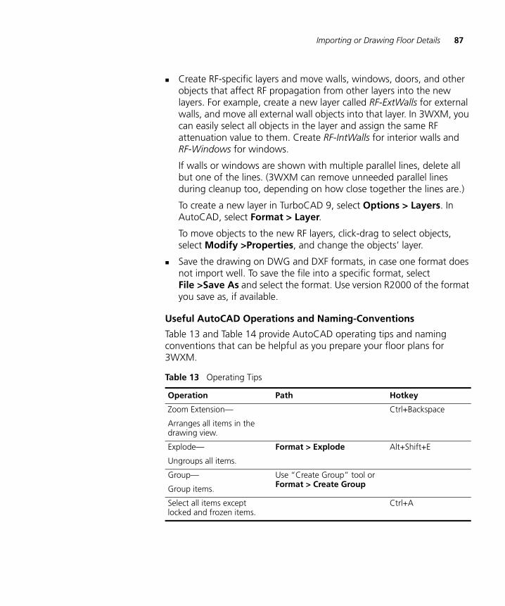
Importing or Drawing Floor Details 87
Create RF-specific layers and move walls, windows, doors, and other objects that affect RF propagation from other layers into the new layers. For example, create a new layer called RF-ExtWalls for external walls, and move all external wall objects into that layer. In 3WXM, you can easily select all objects in the layer and assign the same RF attenuation value to them. Create RF-IntWalls for interior walls and RF-Windows for windows.
If walls or windows are shown with multiple parallel lines, delete all but one of the lines. (3WXM can remove unneeded parallel lines during cleanup too, depending on how close together the lines are.)
To create a new layer in TurboCAD 9, select Options > Layers. In AutoCAD, select Format > Layer.
To move objects to the new RF layers, click-drag to select objects, select Modify >Properties, and change the objects’ layer.
Save the drawing on DWG and DXF formats, in case one format does not import well. To save the file into a specific format, select File >Save As and select the format. Use version R2000 of the format you save as, if available.
Useful AutoCAD Operations and Naming-Conventions
Table 13 and Table 14 provide AutoCAD operating tips and naming conventions that can be helpful as you prepare your floor plans for 3WXM.
Table 13 Operating Tips
Operation Path Hotkey
Zoom Extension—
Arranges all items in the drawing view.
Ctrl+Backspace
Explode—
Ungroups all items.
Format > Explode Alt+Shift+E
Group—
Group items.
Use “Create Group” tool or Format > Create Group
Select all items except locked and frozen items.
Ctrl+A
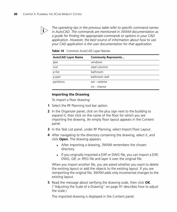
88 CHAPTER 5: PLANNING THE 3COM MOBILITY SYSTEM
The operating tips in the previous table refer to specific command names in AutoCAD. The commands are mentioned in 3WXM documentation as a guide for finding the appropriate commands or options in your CAD application. However, the best source of information about how to use your CAD application is the user documentation for that application.
Importing the Drawing
To import a floor drawing:
1 Select the RF Planning tool bar option.
2 In the Organizer panel, click on the plus sign next to the building to expand it, then click on the name of the floor for which you are importing the drawing. An empty floor layout appears in the Content panel.
3 In the Task List panel, under RF Planning, select Import Floor Layout.
4 After navigating to the directory containing the drawing, select it, and click Open. The drawing appears.
After importing a drawing, 3WXM remembers the chosen directory.
If you originally imported a DXF or DWG file, you can import a DXF, DWG, GIF, or JPEG file and layer it over the original file.
When you import another file, you are asked whether you want to delete the existing layout or add the objects to the existing layout. If you are reimporting the original file, 3WXM adds only incremental changes to the existing layout.
5 Read the message about verifying the drawing scale, then click OK. (“Adjusting the Scale of a Drawing” on page 91 describes how to adjust the scale.)
The imported drawing is displayed in the Content panel.
Table 14 Common AutoCAD Layer Names
AutoCAD Layer Name Commonly Represents...
glaz windows
scol steel columns
p-fixt bathroom
p-part bathroom stall
partitions ext – exterior
int – interior
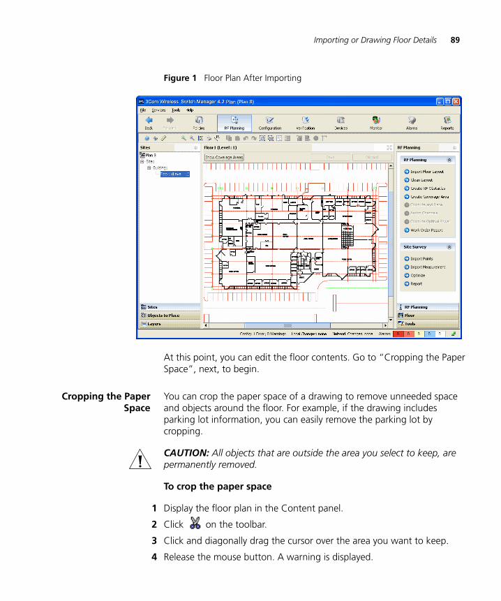
Importing or Drawing Floor Details 89
Figure 1 Floor Plan After Importing
At this point, you can edit the floor contents. Go to “Cropping the Paper Space”, next, to begin.
Cropping the PaperSpace
You can crop the paper space of a drawing to remove unneeded space and objects around the floor. For example, if the drawing includes parking lot information, you can easily remove the parking lot by cropping.
CAUTION: All objects that are outside the area you select to keep, are permanently removed.
To crop the paper space
1 Display the floor plan in the Content panel.
2 Click on the toolbar.
3 Click and diagonally drag the cursor over the area you want to keep.
4 Release the mouse button. A warning is displayed.
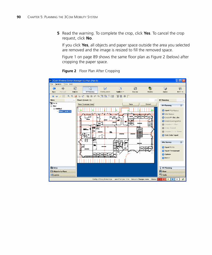
90 CHAPTER 5: PLANNING THE 3COM MOBILITY SYSTEM
5 Read the warning. To complete the crop, click Yes. To cancel the crop request, click No.
If you click Yes, all objects and paper space outside the area you selected are removed and the image is resized to fill the removed space.
Figure 1 on page 89 shows the same floor plan as Figure 2 (below) after cropping the paper space.
Figure 2 Floor Plan After Cropping
Importing or Drawing Floor Details 91
Adjusting the Scale ofa Drawing
If you imported a DWG or DXF drawing, you might need to adjust the scale of the drawing because the units used in these drawings might not have a one-to-one correspondence to meters and feet. To adjust the scale of the drawing, you draw a line between two points of known distance and adjust the measurement.
To adjust the scale
1 Display the floor plan in the Content panel.
2 Click on the toolbar.
3 Drag to create a line between two points. A dialog box appears.
4 In the dialog box, type the actual distance between the two points.
5 Click OK.
Adjusting the OriginPoint
3WXM uses the origin point of a building to understand what is above or below a given floor. When calculating RF coverage, 3WXM needs to understand where MAP access points on adjacent floors are located so that 3WXM can take RF from those MAPs into account when assigning channels.
If an imported drawing has an origin point defined, 3WXM tries to use that origin point. Otherwise, 3WXM places the origin point in the upper left corner of the drawing by default.
You are not required to use the upper left corner of the building as the origin point. You can select an easily identifiable feature on all floors, such as an elevator shaft. Or, to include additional features that are not on the floor itself, you can extend the drawing beyond the exterior walls by moving the origin farther up and left.
To adjust the origin point
1 Access the floor plan in the Edit Content page.
2 Drag and drop (the crosshairs icon) to the new location.
The following graphic shows an example a floor plan with an origin point in the upper left corner of the drawing.
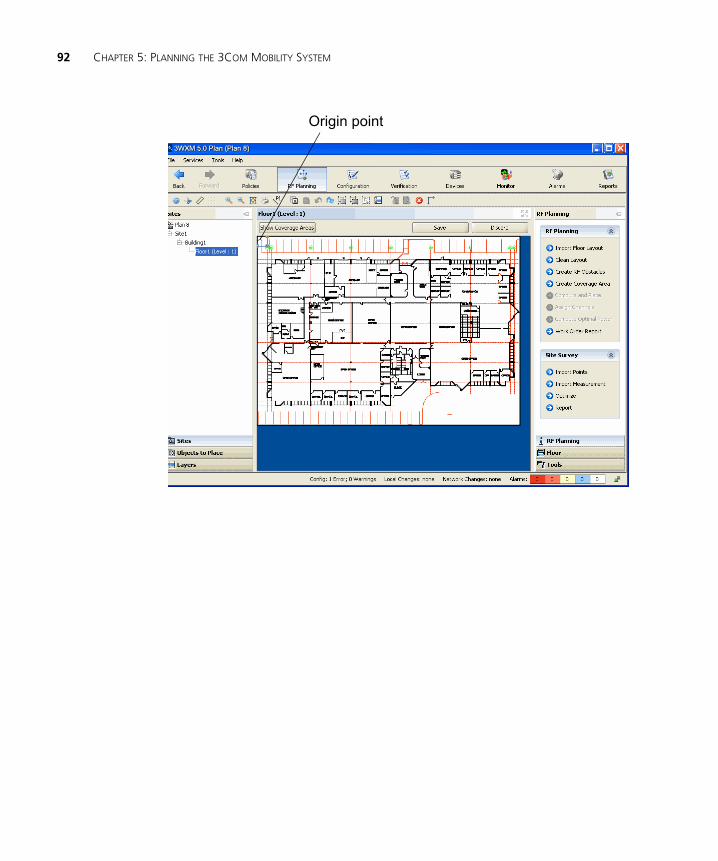
92 CHAPTER 5: PLANNING THE 3COM MOBILITY SYSTEM
Origin point
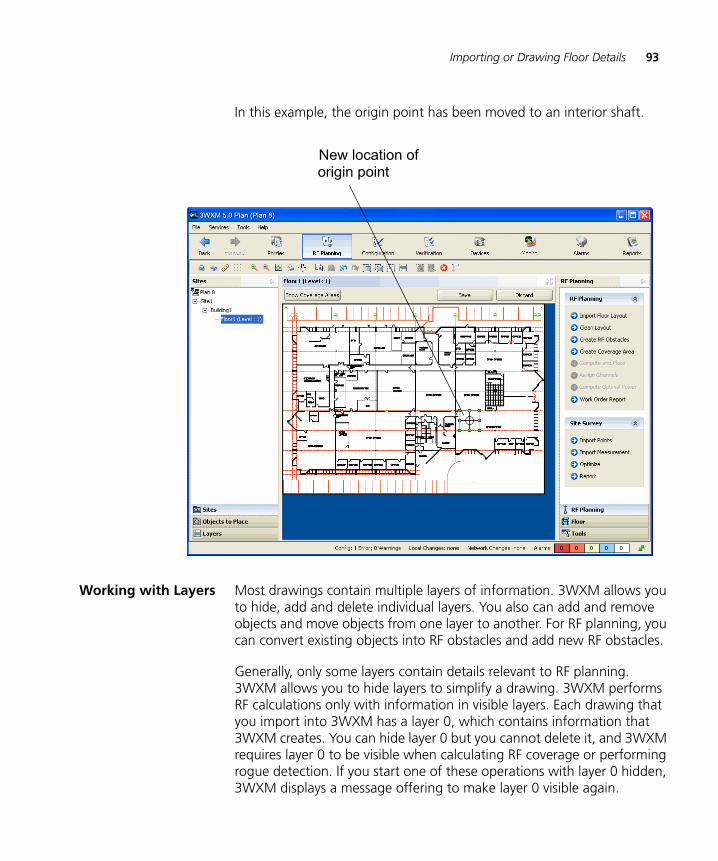
Importing or Drawing Floor Details 93
In this example, the origin point has been moved to an interior shaft.
Working with Layers Most drawings contain multiple layers of information. 3WXM allows you to hide, add and delete individual layers. You also can add and remove objects and move objects from one layer to another. For RF planning, you can convert existing objects into RF obstacles and add new RF obstacles.
Generally, only some layers contain details relevant to RF planning. 3WXM allows you to hide layers to simplify a drawing. 3WXM performs RF calculations only with information in visible layers. Each drawing that you import into 3WXM has a layer 0, which contains information that 3WXM creates. You can hide layer 0 but you cannot delete it, and 3WXM requires layer 0 to be visible when calculating RF coverage or performing rogue detection. If you start one of these operations with layer 0 hidden, 3WXM displays a message offering to make layer 0 visible again.
New location oforigin point
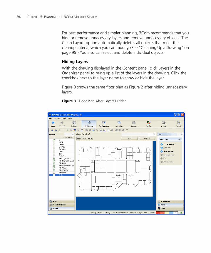
94 CHAPTER 5: PLANNING THE 3COM MOBILITY SYSTEM
For best performance and simpler planning, 3Com recommends that you hide or remove unnecessary layers and remove unnecessary objects. The Clean Layout option automatically deletes all objects that meet the cleanup criteria, which you can modify. (See “Cleaning Up a Drawing” on page 95.) You also can select and delete individual objects.
Hiding Layers
With the drawing displayed in the Content panel, click Layers in the Organizer panel to bring up a list of the layers in the drawing. Click the checkbox next to the layer name to show or hide the layer.
Figure 3 shows the same floor plan as Figure 2 after hiding unnecessary layers.
Figure 3 Floor Plan After Layers Hidden
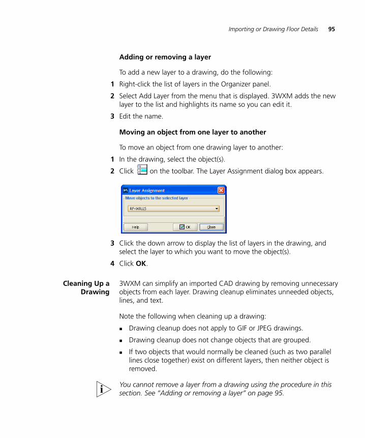
Importing or Drawing Floor Details 95
Adding or removing a layer
To add a new layer to a drawing, do the following:
1 Right-click the list of layers in the Organizer panel.
2 Select Add Layer from the menu that is displayed. 3WXM adds the new layer to the list and highlights its name so you can edit it.
3 Edit the name.
Moving an object from one layer to another
To move an object from one drawing layer to another:
1 In the drawing, select the object(s).
2 Click on the toolbar. The Layer Assignment dialog box appears.
3 Click the down arrow to display the list of layers in the drawing, and select the layer to which you want to move the object(s).
4 Click OK.
Cleaning Up aDrawing
3WXM can simplify an imported CAD drawing by removing unnecessary objects from each layer. Drawing cleanup eliminates unneeded objects, lines, and text.
Note the following when cleaning up a drawing:
Drawing cleanup does not apply to GIF or JPEG drawings.
Drawing cleanup does not change objects that are grouped.
If two objects that would normally be cleaned (such as two parallel lines close together) exist on different layers, then neither object is removed.
You cannot remove a layer from a drawing using the procedure in this section. See “Adding or removing a layer” on page 95.
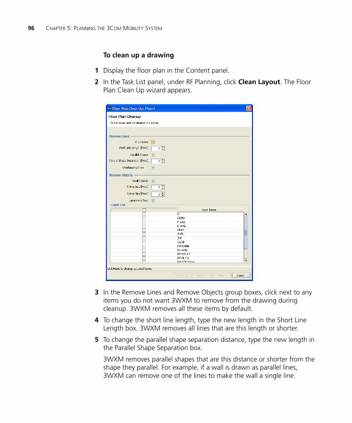
96 CHAPTER 5: PLANNING THE 3COM MOBILITY SYSTEM
To clean up a drawing
1 Display the floor plan in the Content panel.
2 In the Task List panel, under RF Planning, click Clean Layout. The Floor Plan Clean Up wizard appears.
3 In the Remove Lines and Remove Objects group boxes, click next to any items you do not want 3WXM to remove from the drawing during cleanup. 3WXM removes all these items by default.
4 To change the short line length, type the new length in the Short Line Length box. 3WXM removes all lines that are this length or shorter.
5 To change the parallel shape separation distance, type the new length in the Parallel Shape Separation box.
3WXM removes parallel shapes that are this distance or shorter from the shape they parallel. For example, if a wall is drawn as parallel lines, 3WXM can remove one of the lines to make the wall a single line.
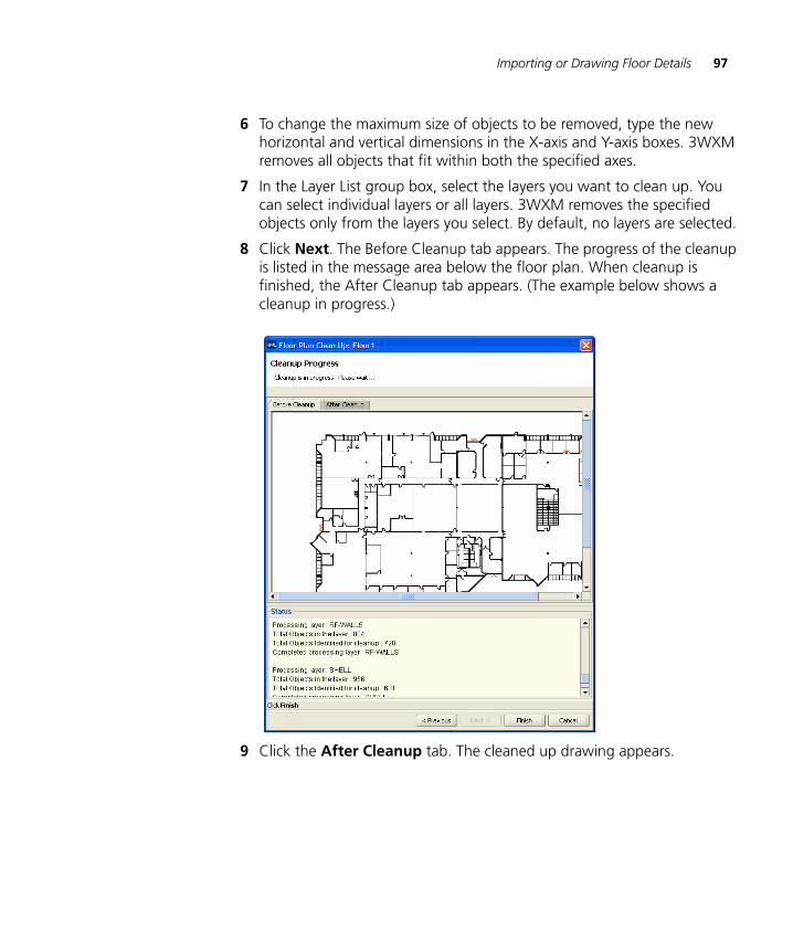
Importing or Drawing Floor Details 97
6 To change the maximum size of objects to be removed, type the new horizontal and vertical dimensions in the X-axis and Y-axis boxes. 3WXM removes all objects that fit within both the specified axes.
7 In the Layer List group box, select the layers you want to clean up. You can select individual layers or all layers. 3WXM removes the specified objects only from the layers you select. By default, no layers are selected.
8 Click Next. The Before Cleanup tab appears. The progress of the cleanup is listed in the message area below the floor plan. When cleanup is finished, the After Cleanup tab appears. (The example below shows a cleanup in progress.)
9 Click the After Cleanup tab. The cleaned up drawing appears.
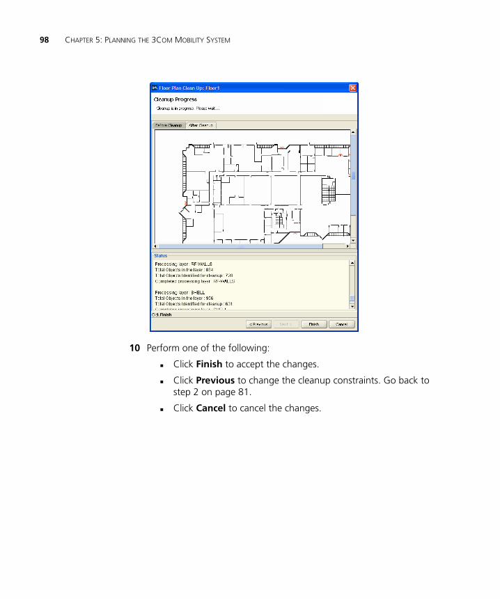
98 CHAPTER 5: PLANNING THE 3COM MOBILITY SYSTEM
10 Perform one of the following:
Click Finish to accept the changes.
Click Previous to change the cleanup constraints. Go back to step 2 on page 81.
Click Cancel to cancel the changes.
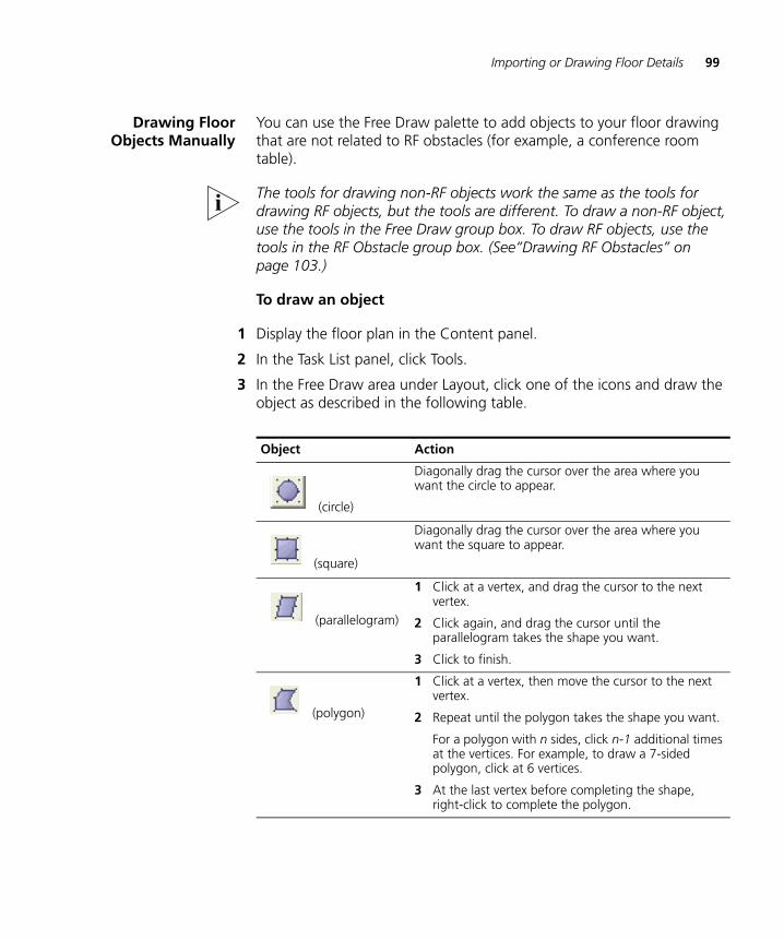
Importing or Drawing Floor Details 99
Drawing FloorObjects Manually
You can use the Free Draw palette to add objects to your floor drawing that are not related to RF obstacles (for example, a conference room table).
The tools for drawing non-RF objects work the same as the tools for drawing RF objects, but the tools are different. To draw a non-RF object, use the tools in the Free Draw group box. To draw RF objects, use the tools in the RF Obstacle group box. (See“Drawing RF Obstacles” on page 103.)
To draw an object
1 Display the floor plan in the Content panel.
2 In the Task List panel, click Tools.
3 In the Free Draw area under Layout, click one of the icons and draw the object as described in the following table.
Object Action
(circle)
Diagonally drag the cursor over the area where you want the circle to appear.
(square)
Diagonally drag the cursor over the area where you want the square to appear.
(parallelogram)
1 Click at a vertex, and drag the cursor to the next vertex.
2 Click again, and drag the cursor until the parallelogram takes the shape you want.
3 Click to finish.
(polygon)
1 Click at a vertex, then move the cursor to the next vertex.
2 Repeat until the polygon takes the shape you want.
For a polygon with n sides, click n-1 additional times at the vertices. For example, to draw a 7-sided polygon, click at 6 vertices.
3 At the last vertex before completing the shape, right-click to complete the polygon.
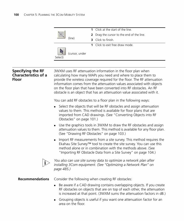
100 CHAPTER 5: PLANNING THE 3COM MOBILITY SYSTEM
Specifying the RF Characteristics of a Floor
3WXM uses RF attenuation information in the floor plan when calculating how many MAPs you need and where to place them to provide the wireless coverage required for the floor. The RF attenuation information comes from the attenuation values associated with objects on the floor plan that have been converted into RF obstacles. An RF obstacle is an object that has an attenuation value associated with it.
You can add RF obstacles to a floor plan in the following ways:
Select the objects that will be RF obstacles and assign attenuation values to them. This method is available for floor plans that are imported from CAD drawings. (See “Converting Objects into RF Obstacles” on page 101.)
Use the graphics tools in 3WXM to draw the RF obstacles and assign attenuation values to them. This method is available for any floor plan. (See “Drawing RF Obstacles” on page 103.)
Import RF measurements from a site survey. This method requires the Ekahau Site Survey™ tool to create the site survey. You can use this method alone or in combination with the methods above. (See “Importing RF Obstacle Data from a Site Survey” on page 104.)
You also can use site survey data to optimize a network plan after installing 3Com equipment. (See “Optimizing a Network Plan” on page 485.)
Recommendations Consider the following when creating RF obstacles:
Be aware if a CAD drawing contains overlapping objects. If you create RF obstacles on objects that are on top of each other, the attenuation is increased at that point. (3WXM sums the attenuation factors in dB.)
Grouping objects is useful if you want one attenuation factor for an area on the floor.
(line)
1 Click at the start of the line.
2 Drag the cursor to the end of the line.
3 Click to finish.
(cursor, under Select)
1 Click to exit free draw mode.
Specifying the RF Characteristics of a Floor 101
Converting Objectsinto RF Obstacles
You have several options when creating RF obstacles:
Convert all objects in a layer of a CAD drawing into RF obstacles.
Convert all objects in an area of the drawing into RF obstacles.
Convert multiple objects in the drawing into RF obstacles.
Convert grouped objects in the drawing into RF obstacles.
To create RF obstacles for all objects in a layer
3WXM preserves the layers defined in a CAD drawing. You can convert all of the objects in the layer into a specific type of RF obstacle.
1 Click Layers in the Organizer panel to bring up a list of the layers in the drawing.
2 Right-click the list of layers in the Organizer panel.
3 Select Create RF Obstacles from the menu that is displayed. The Create RF Obstacle dialog box appears.
4 Go to “To use the Create RF Obstacle Dialog box” on page 102.
To create RF obstacles for an area in a drawing
1 Diagonally drag the cursor over the area where you want to create RF obstacles.
2 Right-click and select Create RF Obstacle. The Create RF Obstacle dialog box appears.
3 Go to “To use the Create RF Obstacle Dialog box” on page 102.
To create RF obstacles for multiple selected objects in a drawing
1 Click an object on the floor.
2 Press Shift while clicking on additional objects.
3 Right-click, and select Create RF Obstacle. The Create RF Obstacle dialog box appears.
4 Go to “To use the Create RF Obstacle Dialog box” on page 102.
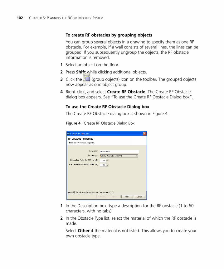
102 CHAPTER 5: PLANNING THE 3COM MOBILITY SYSTEM
To create RF obstacles by grouping objects
You can group several objects in a drawing to specify them as one RF obstacle. For example, if a wall consists of several lines, the lines can be grouped. If you subsequently ungroup the objects, the RF obstacle information is removed.
1 Select an object on the floor.
2 Press Shift while clicking additional objects.
3 Click the (group objects) icon on the toolbar. The grouped objects now appear as one object group.
4 Right-click, and select Create RF Obstacle. The Create RF Obstacle dialog box appears. See “To use the Create RF Obstacle Dialog box”.
To use the Create RF Obstacle Dialog box
The Create RF Obstacle dialog box is shown in Figure 4.
Figure 4 Create RF Obstacle Dialog Box
1 In the Description box, type a description for the RF obstacle (1 to 60 characters, with no tabs).
2 In the Obstacle Type list, select the material of which the RF obstacle is made.
Select Other if the material is not listed. This allows you to create your own obstacle type.
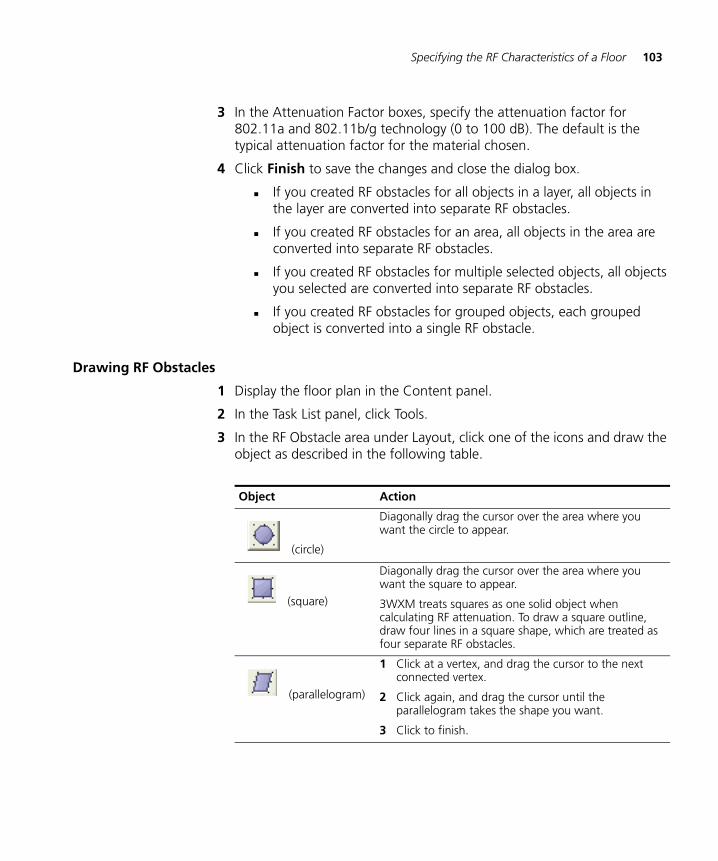
Specifying the RF Characteristics of a Floor 103
3 In the Attenuation Factor boxes, specify the attenuation factor for 802.11a and 802.11b/g technology (0 to 100 dB). The default is the typical attenuation factor for the material chosen.
4 Click Finish to save the changes and close the dialog box.
If you created RF obstacles for all objects in a layer, all objects in the layer are converted into separate RF obstacles.
If you created RF obstacles for an area, all objects in the area are converted into separate RF obstacles.
If you created RF obstacles for multiple selected objects, all objects you selected are converted into separate RF obstacles.
If you created RF obstacles for grouped objects, each grouped object is converted into a single RF obstacle.
Drawing RF Obstacles
1 Display the floor plan in the Content panel.
2 In the Task List panel, click Tools.
3 In the RF Obstacle area under Layout, click one of the icons and draw the object as described in the following table.
Object Action
(circle)
Diagonally drag the cursor over the area where you want the circle to appear.
(square)
Diagonally drag the cursor over the area where you want the square to appear.
3WXM treats squares as one solid object when calculating RF attenuation. To draw a square outline, draw four lines in a square shape, which are treated as four separate RF obstacles.
(parallelogram)
1 Click at a vertex, and drag the cursor to the next connected vertex.
2 Click again, and drag the cursor until the parallelogram takes the shape you want.
3 Click to finish.
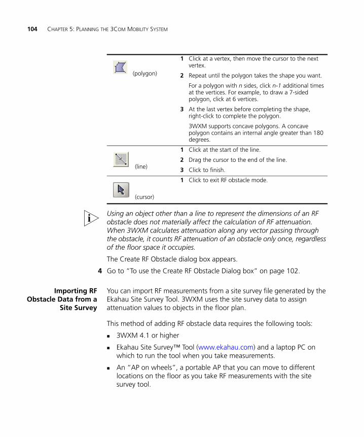
104 CHAPTER 5: PLANNING THE 3COM MOBILITY SYSTEM
Using an object other than a line to represent the dimensions of an RF obstacle does not materially affect the calculation of RF attenuation. When 3WXM calculates attenuation along any vector passing through the obstacle, it counts RF attenuation of an obstacle only once, regardless of the floor space it occupies.
The Create RF Obstacle dialog box appears.
4 Go to “To use the Create RF Obstacle Dialog box” on page 102.
Importing RFObstacle Data from a
Site Survey
You can import RF measurements from a site survey file generated by the Ekahau Site Survey Tool. 3WXM uses the site survey data to assign attenuation values to objects in the floor plan.
This method of adding RF obstacle data requires the following tools:
3WXM 4.1 or higher
Ekahau Site Survey™ Tool (www.ekahau.com) and a laptop PC on which to run the tool when you take measurements.
An “AP on wheels”, a portable AP that you can move to different locations on the floor as you take RF measurements with the site survey tool.
(polygon)
1 Click at a vertex, then move the cursor to the next vertex.
2 Repeat until the polygon takes the shape you want.
For a polygon with n sides, click n-1 additional times at the vertices. For example, to draw a 7-sided polygon, click at 6 vertices.
3 At the last vertex before completing the shape, right-click to complete the polygon.
3WXM supports concave polygons. A concave polygon contains an internal angle greater than 180 degrees.
(line)
1 Click at the start of the line.
2 Drag the cursor to the end of the line.
3 Click to finish.
(cursor)
1 Click to exit RF obstacle mode.
Specifying the RF Characteristics of a Floor 105
To use this method, perform the following tasks:
1 In 3WXM, identify the major RF obstacles and assign an attenuation value to them. You can select any attenuation value. 3WXM will use the RF measurement data from the site survey to correct the attenuation values. (See “Converting Objects into RF Obstacles” on page 101 and “Drawing RF Obstacles” on page 103.)
3WXM also can create new obstacles based on the RF measurement data. But adding major obstacles before you import the survey results helps 3WXM provide a more complete set of RF obstacles.
2 In 3WXM, indicate the positions where you will place the portable AP. These positions are line of sight (LOS) points. You can create the LOS points in 3WXM or import them from a comma separated values (CSV) file. In either case, you must assign a unique MAC address to each LOS. Even though each LOS will use the same portable AP, each position where you use the AP must have a unique MAC address. (See “Adding LOS Points” on page 106.)
You can place the LOS points at the places where you are thinking of installing the permanent MAPs, but this is not a requirement.
3 In 3WXM, generate a site survey order. The site survey order includes the locations and MAC addresses of the LOS points, and also provides a GIF image of the floor. (See “Generating a Site Survey Order” on page 112.)
4 In the site survey tool, import the GIF of the floor plan and use the map name specified in the site survey work order.
5 Place the portable AP at the first LOS position and assign it the MAC address specified in the work order. Start the site survey tool on the laptop PC and take the measurements. (See the Ekahau site survey documentation for specific instructions.)
6 In 3WXM, import the RF measurements from the site survey file. (See “Importing RF Measurements” on page 114.)
7 In 3WXM, build the attenuation library. This task updates the attenuation of RF obstacles that are already in the plan. In addition, this step adds any new obstacles detected during the survey. (See “Applying the RF Measurements to the Floor Plan” on page 116.)
8 In 3WXM, define wireless coverage areas. (See “Defining Wireless Coverage Areas” on page 117.)
106 CHAPTER 5: PLANNING THE 3COM MOBILITY SYSTEM
Site Survey Recommendations
This manual does not describe how to use the site survey application. For this information, consult the Ekahau site survey documentation.
When conducting the survey, use the following best practices for optimal results:
Verify that the scale of the floor plan is correct before generating a work order. If you use a drawing of the floor that is from another source, make sure the scale of the drawing is correct.
Use an AP with an omnidirectional antenna, instead of a directional antenna.
Run the AP at full power in each location.
Make sure to use a unique MAC address at each of the portable AP locations. If you accidentally use the same MAC address for multiple locations, the RF measurement data will be inaccurate.
While conducting the survey:
Walk slowly and evenly, and click at each turn.
Walk completely around the area you are surveying, completing a 360-degree scan of the area.
Avoid placing your body between the AP and the laptop PC. Your body adds attenuation.
Adding LOS Points
Line of sight (LOS) points are the locations for the portable AP. You must add the LOS points to the floor plan before you generate a site survey order. You can add LOS points by importing them from a file or by creating them in 3WXM.
To import LOS points from a file
1 Use the site survey tool or some other means to prepare a csv file containing the MAC addresses of each LOS point.
2 Display the floor plan in the Content panel.
3 In the Task List panel, click RF Planning.
4 Under Site Survey, click Import Points. The Import AP Placement Points dialog is displayed.
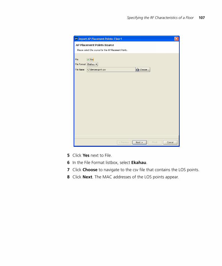
Specifying the RF Characteristics of a Floor 107
5 Click Yes next to File.
6 In the File Format listbox, select Ekahau.
7 Click Choose to navigate to the csv file that contains the LOS points.
8 Click Next. The MAC addresses of the LOS points appear.
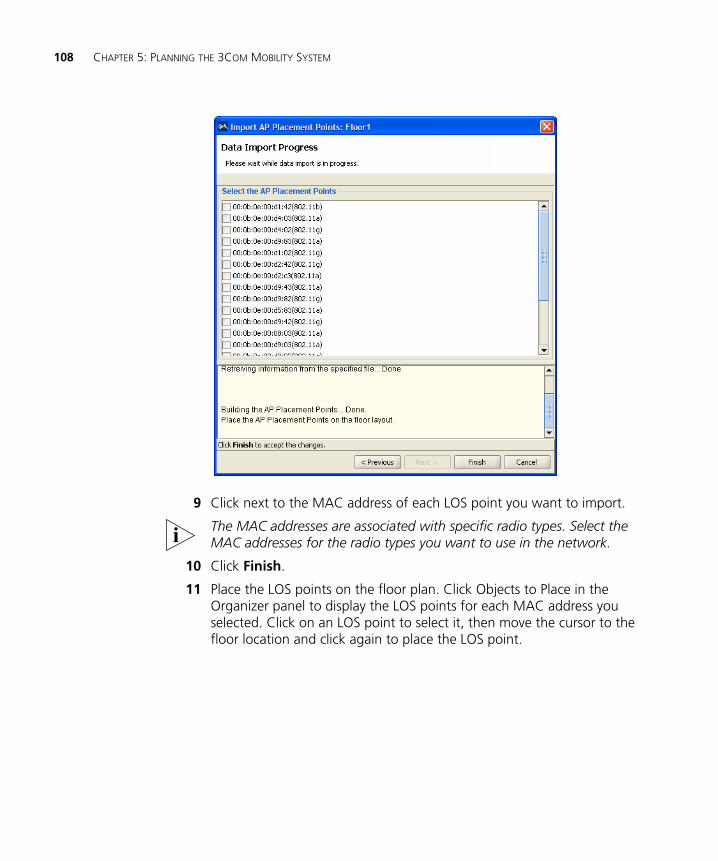
108 CHAPTER 5: PLANNING THE 3COM MOBILITY SYSTEM
9 Click next to the MAC address of each LOS point you want to import.
The MAC addresses are associated with specific radio types. Select the MAC addresses for the radio types you want to use in the network.
10 Click Finish.
11 Place the LOS points on the floor plan. Click Objects to Place in the Organizer panel to display the LOS points for each MAC address you selected. Click on an LOS point to select it, then move the cursor to the floor location and click again to place the LOS point.
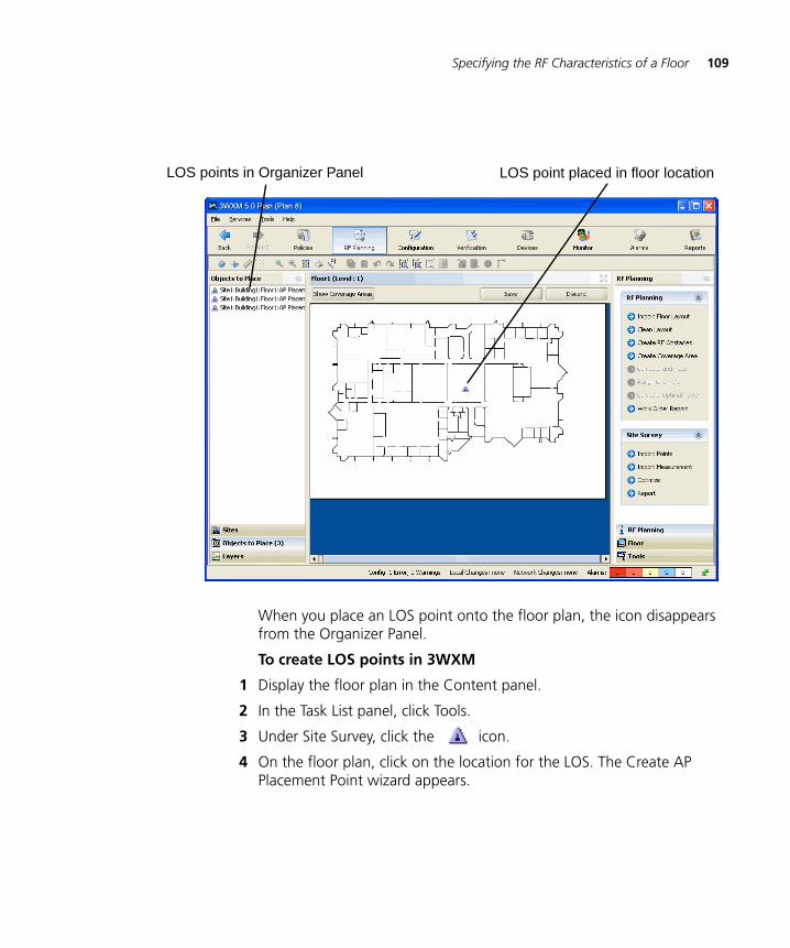
Specifying the RF Characteristics of a Floor 109
When you place an LOS point onto the floor plan, the icon disappears from the Organizer Panel.
To create LOS points in 3WXM
1 Display the floor plan in the Content panel.
2 In the Task List panel, click Tools.
3 Under Site Survey, click the icon.
4 On the floor plan, click on the location for the LOS. The Create AP Placement Point wizard appears.
LOS points in Organizer Panel LOS point placed in floor location
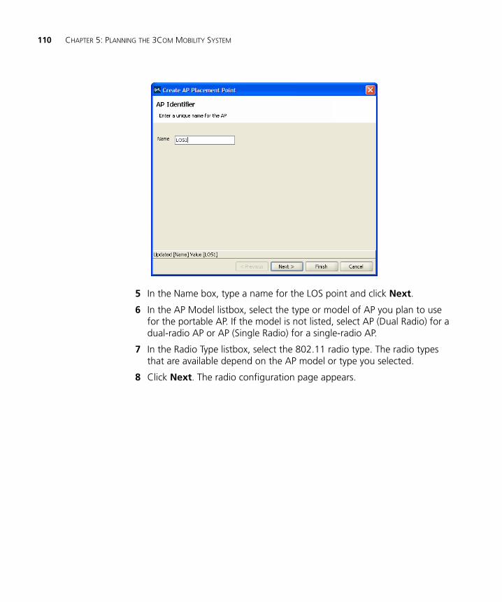
110 CHAPTER 5: PLANNING THE 3COM MOBILITY SYSTEM
5 In the Name box, type a name for the LOS point and click Next.
6 In the AP Model listbox, select the type or model of AP you plan to use for the portable AP. If the model is not listed, select AP (Dual Radio) for a dual-radio AP or AP (Single Radio) for a single-radio AP.
7 In the Radio Type listbox, select the 802.11 radio type. The radio types that are available depend on the AP model or type you selected.
8 Click Next. The radio configuration page appears.
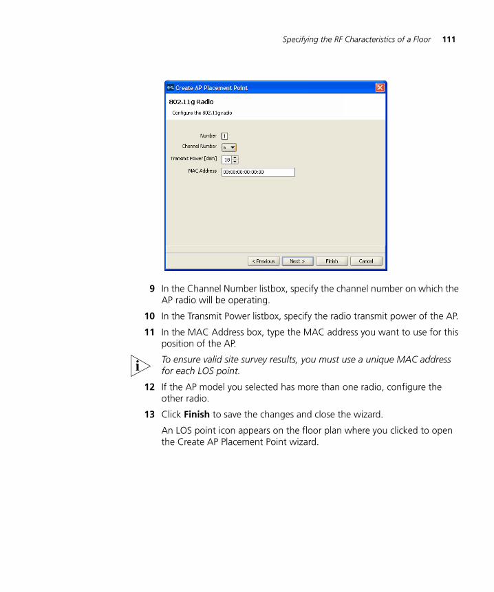
Specifying the RF Characteristics of a Floor 111
9 In the Channel Number listbox, specify the channel number on which the AP radio will be operating.
10 In the Transmit Power listbox, specify the radio transmit power of the AP.
11 In the MAC Address box, type the MAC address you want to use for this position of the AP.
To ensure valid site survey results, you must use a unique MAC address for each LOS point.
12 If the AP model you selected has more than one radio, configure the other radio.
13 Click Finish to save the changes and close the wizard.
An LOS point icon appears on the floor plan where you clicked to open the Create AP Placement Point wizard.
112 CHAPTER 5: PLANNING THE 3COM MOBILITY SYSTEM
To move an LOS point
To move an LOS icon, click-and-drag to select the icon and move it to its new location.
To temporarily remove an LOS point onto the Objects to Place tab
To temporarily remove an LOS point from the floor without deleting it, click and drag the LOS icon to the Objects To Place area of the Organizer panel.
To move the LOS back onto the floor:
1 Click on the LOS in the Objects To Place area of the Organizer panel.
2 Move the cursor to the floor location where you want to place the LOS.
3 Click to place the LOS.
You cannot delete an LOS point directly from the Objects To Place tab. To delete an LOS point, place the LOS point somewhere on the floor space, then delete it. (See “To delete an LOS point”.)
To delete an LOS point
To permanently remove an LOS icon from the floor:
1 Right-click on the LOS icon.
2 Select Delete. The Delete Objects wizard appears.
3 Click Finish to confirm the deletion.
Generating a Site Survey Order
1 Display the floor plan in the Content panel.
2 In the Task List panel, click RF Planning.
3 Under Site Survey, click Report. The Site Survey Order Generation dialog is displayed.
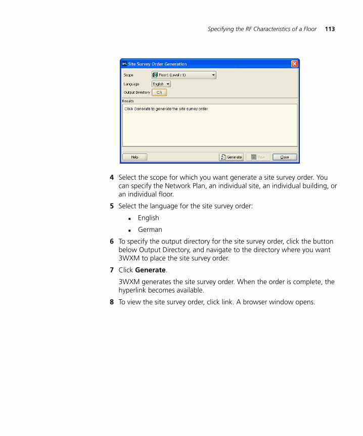
Specifying the RF Characteristics of a Floor 113
4 Select the scope for which you want generate a site survey order. You can specify the Network Plan, an individual site, an individual building, or an individual floor.
5 Select the language for the site survey order:
English
German
6 To specify the output directory for the site survey order, click the button below Output Directory, and navigate to the directory where you want 3WXM to place the site survey order.
7 Click Generate.
3WXM generates the site survey order. When the order is complete, the hyperlink becomes available.
8 To view the site survey order, click link. A browser window opens.
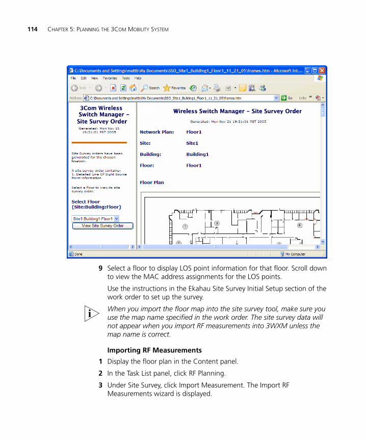
114 CHAPTER 5: PLANNING THE 3COM MOBILITY SYSTEM
9 Select a floor to display LOS point information for that floor. Scroll down to view the MAC address assignments for the LOS points.
Use the instructions in the Ekahau Site Survey Initial Setup section of the work order to set up the survey.
When you import the floor map into the site survey tool, make sure you use the map name specified in the work order. The site survey data will not appear when you import RF measurements into 3WXM unless the map name is correct.
Importing RF Measurements
1 Display the floor plan in the Content panel.
2 In the Task List panel, click RF Planning.
3 Under Site Survey, click Import Measurement. The Import RF Measurements wizard is displayed.
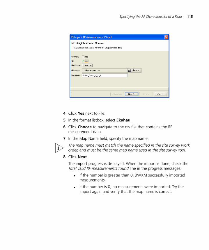
Specifying the RF Characteristics of a Floor 115
4 Click Yes next to File.
5 In the format listbox, select Ekahau.
6 Click Choose to navigate to the csv file that contains the RF measurement data.
7 In the Map Name field, specify the map name.
The map name must match the name specified in the site survey work order, and must be the same map name used in the site survey tool.
8 Click Next.
The import progress is displayed. When the import is done, check the Total valid RF measurements found line in the progress messages.
If the number is greater than 0, 3WXM successfully imported measurements.
If the number is 0, no measurements were imported. Try the import again and verify that the map name is correct.
116 CHAPTER 5: PLANNING THE 3COM MOBILITY SYSTEM
Applying the RF Measurements to the Floor Plan
1 Under Site Survey in the Task List panel, click Optimize.
A wizard appears, listing the progress of the request.
The Total number of RF measurements that did not intersect any object line lists the number of measurements that did not experience attenuation due to an RF obstacle in the path between them.
If the measurements came from a site survey file, they are measurements between the portable AP (LOS point) and the PC running the site survey tool. If the measurements came from MAP radios in the network, they are measurements between MAP radios.
The Total number of objects that will be corrected line indicates the number of measurements that did experience attenuation. For existing RF objects, 3WXM corrects the attenuation to match the results. If the floor plan does not have an RF obstacle where the attenuation library indicates one exists, 3WXM creates an RF obstacle.
For RF obstacles created by 3WXM, the description is auto-generated and the obstacle type is Other. You can edit these values by selecting the obstacle, clicking the Edit properties icon to open the Modify RF Obstacle wizard, and modifying the values. Click OK to close the wizard and save the changes. (See “To use the Create RF Obstacle Dialog box” on page 102. The wizard is the same whether it is labeled Create or Modify.)
2 Click Finish.
Defining Wireless Coverage Areas 117
Defining Wireless Coverage Areas
You must define which areas of your enterprise require wireless network coverage. In 3WXM, you plan for both coverage and capacity requirements in a particular area on the floor. Capacity requirements are determined by the number of users in the area and the amount of wireless network bandwidth desired for every user.
The floor of a building can contain multiple coverage areas if several groups of users on the floor require different bandwidth. For example, an engineering department might have its own coverage area to accommodate a need for higher bandwidth, but the rest of the floor might be planned for general use with lower bandwidth requirements.
You must also identify the wireless technology required (802.11a or 802.11b/g) for coverage areas. For areas requiring multiple wireless technologies, two completely overlapping coverage areas are created—one for 802.11a and one for 802.11b/g.
You define coverage by creating the following items:
Wiring closets (at least one is required if you plan to install directly connected MAPs). See “Creating a Wiring Closet” on page 117.
Coverage areas (required). See “Defining a Coverage Area” on page 119.
RF measurement points (optional). See “Showing RF Coverage” on page 157.
Third-party access points (optional).
Creating a WiringCloset
A wiring closet is a room that contains networking devices, such as switches. If you have an existing wiring closet, you can draw it on the floor layout.
If you have previously installed WX switches and defined them in 3WXM, you can place them in the wiring closet and specify them as switches to be used when 3WXM calculates how many MAP access points are required. If you do not have any WX switches placed in the wiring closet, 3WXM automatically creates and configures the switches that are needed.
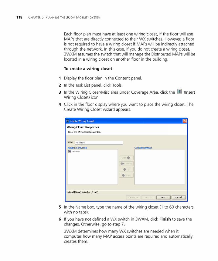
118 CHAPTER 5: PLANNING THE 3COM MOBILITY SYSTEM
Each floor plan must have at least one wiring closet, if the floor will use MAPs that are directly connected to their WX switches. However, a floor is not required to have a wiring closet if MAPs will be indirectly attached through the network. In this case, if you do not create a wiring closet, 3WXM assumes the switch that will manage the Distributed MAPs will be located in a wiring closet on another floor in the building.
To create a wiring closet
1 Display the floor plan in the Content panel.
2 In the Task List panel, click Tools.
3 In the Wiring Closer/Misc area under Coverage Area, click the (Insert Wiring Closet) icon.
4 Click in the floor display where you want to place the wiring closet. The Create Wiring Closet wizard appears.
5 In the Name box, type the name of the wiring closet (1 to 60 characters, with no tabs).
6 If you have not defined a WX switch in 3WXM, click Finish to save the changes. Otherwise, go to step 7.
3WXM determines how many WX switches are needed when it computes how many MAP access points are required and automatically creates them.
Defining Wireless Coverage Areas 119
7 To add a WX switch you previously created to the wiring closet, click the WX switch in the Available Devices box, then click the Add button to move it to the Current Devices box.
To remove a WX switch from the wiring closet, click the WX switch in the Current Devices box, then click the Remove button to move it to the Available Devices box.
If there are two or more WX switches in the wiring closet, you can change the order in which 3WXM checks switches for free ports. If there are no free ports on the switches listed, 3WXM creates and inserts a new switch in the wiring closet. Select a WX switch and click the Up or Down buttons to change the order of the switches.
8 Click Finish to save the changes.
Defining a CoverageArea
Using the coverage area drawing tool, you can specify the coverage area graphically on your floor plan.
You perform the following tasks to define a coverage area:
1 “Drawing a Coverage Area” on page 121
2 “Specifying the Wireless Technology for a Coverage Area” on page 123
3 “Specifying Coverage Area Properties” on page 124
4 “Specifying Floor Properties for the Coverage Area” on page 125
5 “Specifying Default Device Settings for the Coverage Area” on page 126
6 “Specifying Redundancy Computation for MAPs in the Coverage Area” on page 127
7 “Configuring Capacity Calculation for Data” on page 129
8 “Configuring Capacity Calculation for Voice” on page 130
9 “Specifying Mobility Domain, Radio Profile, and Wiring Closet Associations” on page 132
Shared Coverage Areas
3WXM supports the sharing of coverage areas if one area is completely within a larger area. For example, you might want to provide 802.11a and 802.11b coverage in a conference room that is part of a larger coverage area only providing 802.11a coverage. (Coverage areas that partially overlap are not supported.) MAP access points are shared only in the overlapped area.
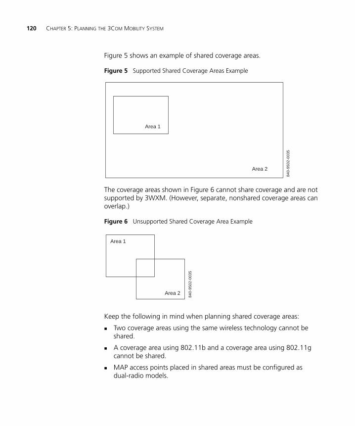
120 CHAPTER 5: PLANNING THE 3COM MOBILITY SYSTEM
Figure 5 shows an example of shared coverage areas.
Figure 5 Supported Shared Coverage Areas Example
The coverage areas shown in Figure 6 cannot share coverage and are not supported by 3WXM. (However, separate, nonshared coverage areas can overlap.)
Figure 6 Unsupported Shared Coverage Area Example
Keep the following in mind when planning shared coverage areas:
Two coverage areas using the same wireless technology cannot be shared.
A coverage area using 802.11b and a coverage area using 802.11g cannot be shared.
MAP access points placed in shared areas must be configured as dual-radio models.
840-
9502
-003
5
Area 1
Area 2
840-
9502
-003
5
Area 1
Area 2

Defining Wireless Coverage Areas 121
Drawing a Coverage Area
3WXM supports concave polygons, which have an internal angle greater than 180 degrees. When drawing a polygon, make sure that two sides of the polygon do not intersect each other, as shown in Figure 7. Also make sure start and end points and the vertices are not too close.
Figure 7 Unsupported Polygon Shape
If you are using a complex concave polygon as a coverage area, computation of MAP access points might take longer than the computation for an area with a less complicated shape.
When drawing a coverage area, make sure it extends just short of external walls. If the coverage area includes external walls, 3WXM accounts for the external walls when computing how many MAP access points are required for the coverage area. This might lead to an inaccurate MAP count.
1 Display the floor plan in the Content panel.
2 In the Task List panel, click Tools.
3 In the Create area under Coverage Area, click one of the icons and draw the object as described in the following table.
840-
9502
-003
6
Object Action
(circle)
Diagonally drag the cursor over the area where you want the circle to appear.
(square)
Diagonally drag the cursor over the area where you want the square to appear.
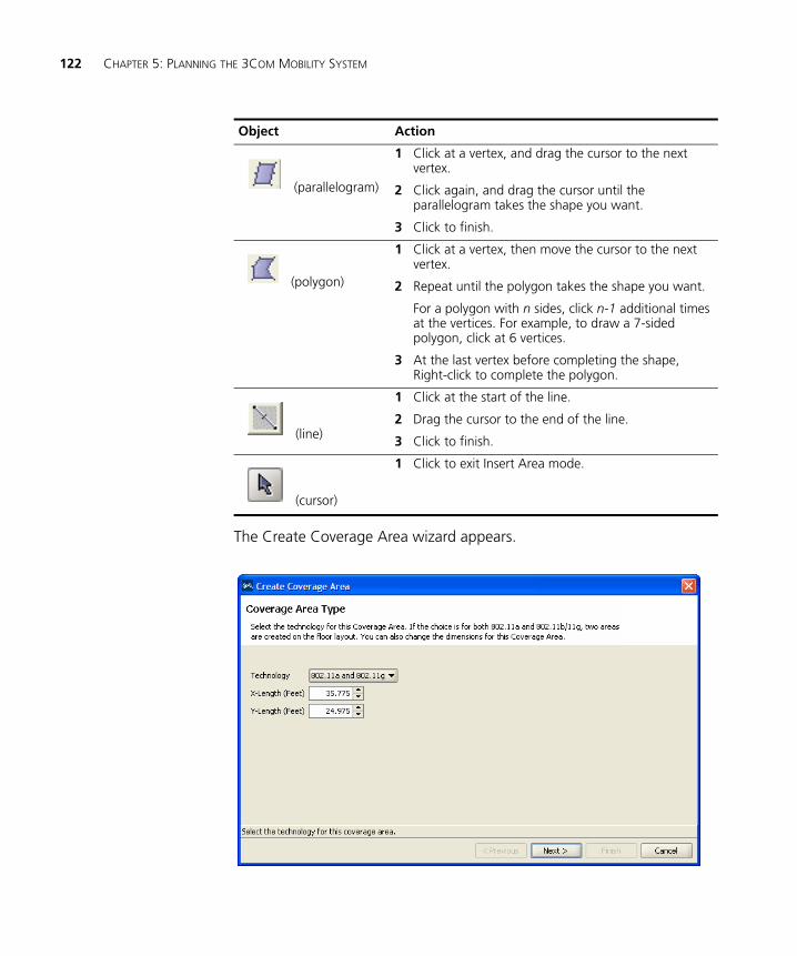
122 CHAPTER 5: PLANNING THE 3COM MOBILITY SYSTEM
The Create Coverage Area wizard appears.
Object Action
(parallelogram)
1 Click at a vertex, and drag the cursor to the next vertex.
2 Click again, and drag the cursor until the parallelogram takes the shape you want.
3 Click to finish.
(polygon)
1 Click at a vertex, then move the cursor to the next vertex.
2 Repeat until the polygon takes the shape you want.
For a polygon with n sides, click n-1 additional times at the vertices. For example, to draw a 7-sided polygon, click at 6 vertices.
3 At the last vertex before completing the shape, Right-click to complete the polygon.
(line)
1 Click at the start of the line.
2 Drag the cursor to the end of the line.
3 Click to finish.
(cursor)
1 Click to exit Insert Area mode.
Defining Wireless Coverage Areas 123
Go to “Specifying the Wireless Technology for a Coverage Area”.
Specifying the Wireless Technology for a Coverage Area
(To draw a coverage area, see “Drawing a Coverage Area” on page 121.) To specify wireless technology for a coverage area:
1 In the Technology list, select one of the following:
802.11a
802.11b
802.11g
802.11a and 802.11b
802.11a and 802.11g
Select 802.11a and 802.11b if the area requires 802.11a and 802.11b coverage. Select 802.11a and 802.11g if the area requires 802.11a and 802.11g coverage.
When you specify a coverage area requiring different technologies, 3WXM creates two areas that completely overlap each other: one area for 802.11a and another for 802.11b/g. An area requiring 802.11a and 802.11b uses a dual-radio MAP model for calculation even if you specify a single-radio MAP.
2 To refine the dimensions of the coverage area, specify the appropriate dimension in the X-Length and Y-Length boxes.
3 Click Next.
The wizard presents properties and association pages for the technology you chose in step 1. The following example shows the wizard for 802.11a and 802.11g technologies.
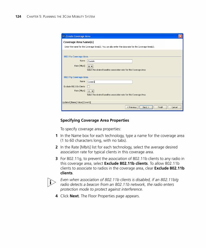
124 CHAPTER 5: PLANNING THE 3COM MOBILITY SYSTEM
Specifying Coverage Area Properties
To specify coverage area properties:
1 In the Name box for each technology, type a name for the coverage area (1 to 60 characters long, with no tabs).
2 In the Rate [Mb/s] list for each technology, select the average desired association rate for typical clients in this coverage area.
3 For 802.11g, to prevent the association of 802.11b clients to any radio in this coverage area, select Exclude 802.11b clients. To allow 802.11b clients to associate to radios in the coverage area, clear Exclude 802.11b clients.
Even when association of 802.11b clients is disabled, if an 802.11b/g radio detects a beacon from an 802.11b network, the radio enters protection mode to protect against interference.
4 Click Next. The Floor Properties page appears.
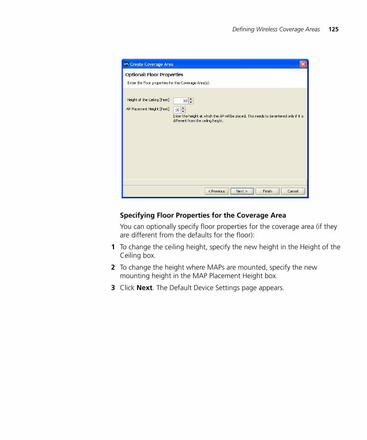
Defining Wireless Coverage Areas 125
Specifying Floor Properties for the Coverage Area
You can optionally specify floor properties for the coverage area (if they are different from the defaults for the floor):
1 To change the ceiling height, specify the new height in the Height of the Ceiling box.
2 To change the height where MAPs are mounted, specify the new mounting height in the MAP Placement Height box.
3 Click Next. The Default Device Settings page appears.
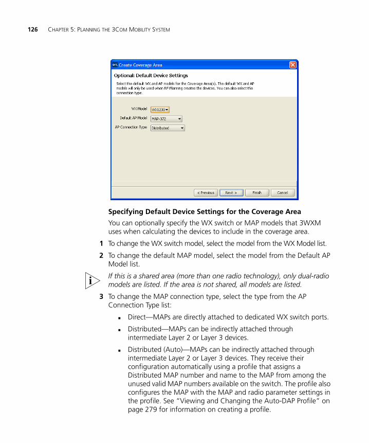
126 CHAPTER 5: PLANNING THE 3COM MOBILITY SYSTEM
Specifying Default Device Settings for the Coverage Area
You can optionally specify the WX switch or MAP models that 3WXM uses when calculating the devices to include in the coverage area.
1 To change the WX switch model, select the model from the WX Model list.
2 To change the default MAP model, select the model from the Default AP Model list.
If this is a shared area (more than one radio technology), only dual-radio models are listed. If the area is not shared, all models are listed.
3 To change the MAP connection type, select the type from the AP Connection Type list:
Direct—MAPs are directly attached to dedicated WX switch ports.
Distributed—MAPs can be indirectly attached through intermediate Layer 2 or Layer 3 devices.
Distributed (Auto)—MAPs can be indirectly attached through intermediate Layer 2 or Layer 3 devices. They receive their configuration automatically using a profile that assigns a Distributed MAP number and name to the MAP from among the unused valid MAP numbers available on the switch. The profile also configures the MAP with the MAP and radio parameter settings in the profile. See “Viewing and Changing the Auto-DAP Profile” on page 279 for information on creating a profile.
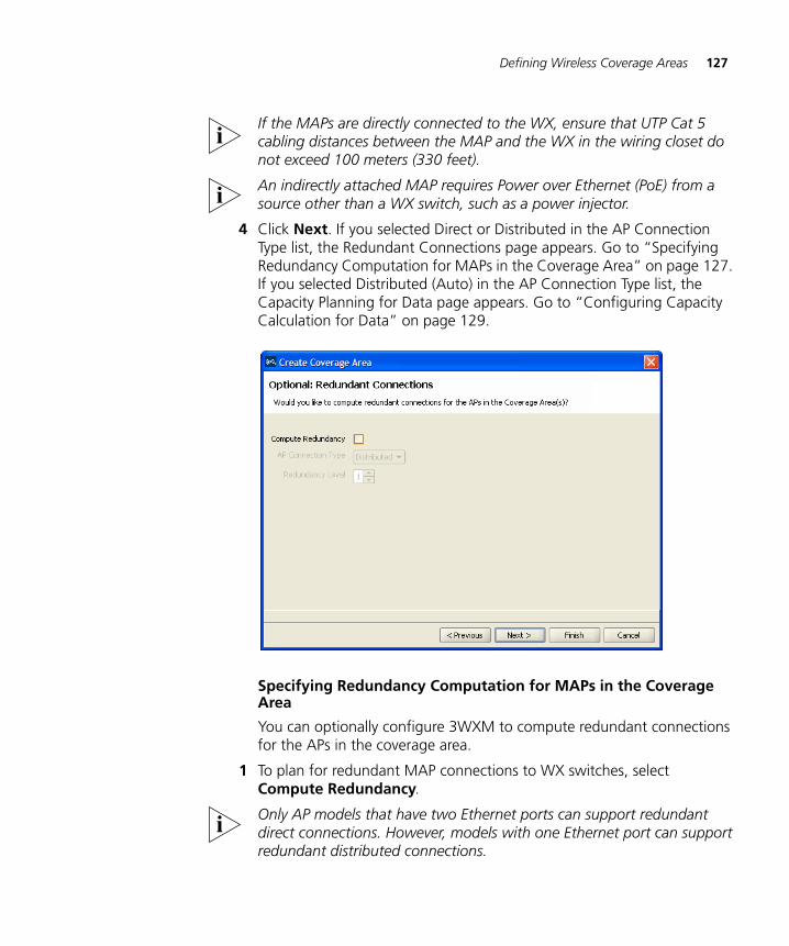
Defining Wireless Coverage Areas 127
If the MAPs are directly connected to the WX, ensure that UTP Cat 5 cabling distances between the MAP and the WX in the wiring closet do not exceed 100 meters (330 feet).
An indirectly attached MAP requires Power over Ethernet (PoE) from a source other than a WX switch, such as a power injector.
4 Click Next. If you selected Direct or Distributed in the AP Connection Type list, the Redundant Connections page appears. Go to “Specifying Redundancy Computation for MAPs in the Coverage Area” on page 127. If you selected Distributed (Auto) in the AP Connection Type list, the Capacity Planning for Data page appears. Go to “Configuring Capacity Calculation for Data” on page 129.
Specifying Redundancy Computation for MAPs in the Coverage Area
You can optionally configure 3WXM to compute redundant connections for the APs in the coverage area.
1 To plan for redundant MAP connections to WX switches, select Compute Redundancy.
Only AP models that have two Ethernet ports can support redundant direct connections. However, models with one Ethernet port can support redundant distributed connections.
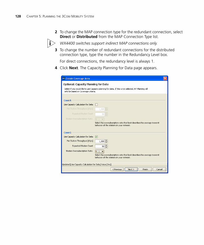
128 CHAPTER 5: PLANNING THE 3COM MOBILITY SYSTEM
2 To change the MAP connection type for the redundant connection, select Direct or Distributed from the MAP Connection Type list.
WX4400 switches support indirect MAP connections only.
3 To change the number of redundant connections for the distributed connection type, type the number in the Redundancy Level box.
For direct connections, the redundancy level is always 1.
4 Click Next. The Capacity Planning for Data page appears.
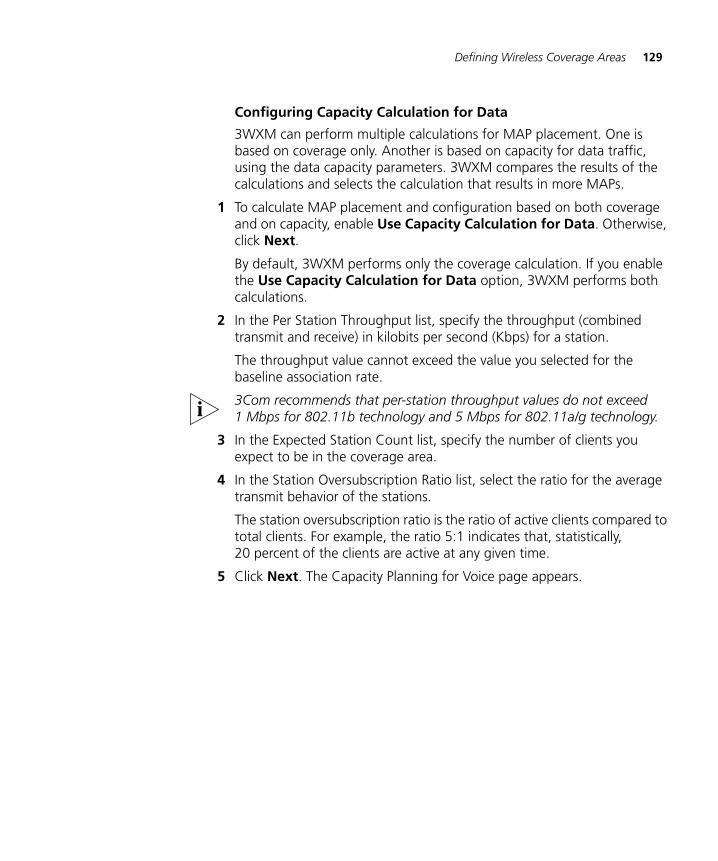
Defining Wireless Coverage Areas 129
Configuring Capacity Calculation for Data
3WXM can perform multiple calculations for MAP placement. One is based on coverage only. Another is based on capacity for data traffic, using the data capacity parameters. 3WXM compares the results of the calculations and selects the calculation that results in more MAPs.
1 To calculate MAP placement and configuration based on both coverage and on capacity, enable Use Capacity Calculation for Data. Otherwise, click Next.
By default, 3WXM performs only the coverage calculation. If you enable the Use Capacity Calculation for Data option, 3WXM performs both calculations.
2 In the Per Station Throughput list, specify the throughput (combined transmit and receive) in kilobits per second (Kbps) for a station.
The throughput value cannot exceed the value you selected for the baseline association rate.
3Com recommends that per-station throughput values do not exceed 1 Mbps for 802.11b technology and 5 Mbps for 802.11a/g technology.
3 In the Expected Station Count list, specify the number of clients you expect to be in the coverage area.
4 In the Station Oversubscription Ratio list, select the ratio for the average transmit behavior of the stations.
The station oversubscription ratio is the ratio of active clients compared to total clients. For example, the ratio 5:1 indicates that, statistically, 20 percent of the clients are active at any given time.
5 Click Next. The Capacity Planning for Voice page appears.
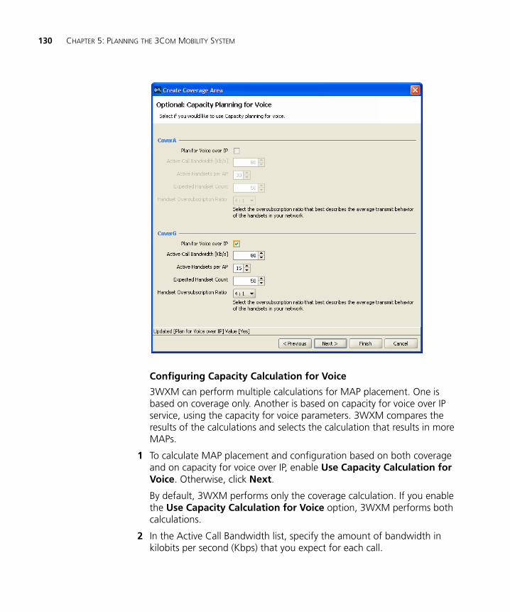
130 CHAPTER 5: PLANNING THE 3COM MOBILITY SYSTEM
Configuring Capacity Calculation for Voice
3WXM can perform multiple calculations for MAP placement. One is based on coverage only. Another is based on capacity for voice over IP service, using the capacity for voice parameters. 3WXM compares the results of the calculations and selects the calculation that results in more MAPs.
1 To calculate MAP placement and configuration based on both coverage and on capacity for voice over IP, enable Use Capacity Calculation for Voice. Otherwise, click Next.
By default, 3WXM performs only the coverage calculation. If you enable the Use Capacity Calculation for Voice option, 3WXM performs both calculations.
2 In the Active Call Bandwidth list, specify the amount of bandwidth in kilobits per second (Kbps) that you expect for each call.
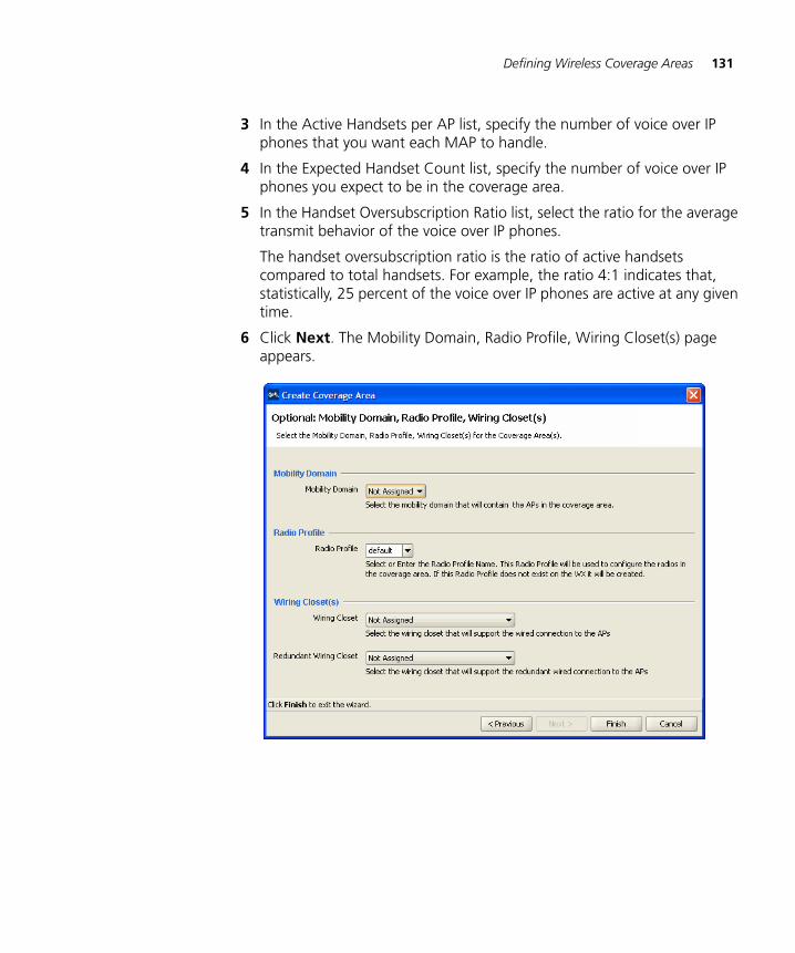
Defining Wireless Coverage Areas 131
3 In the Active Handsets per AP list, specify the number of voice over IP phones that you want each MAP to handle.
4 In the Expected Handset Count list, specify the number of voice over IP phones you expect to be in the coverage area.
5 In the Handset Oversubscription Ratio list, select the ratio for the average transmit behavior of the voice over IP phones.
The handset oversubscription ratio is the ratio of active handsets compared to total handsets. For example, the ratio 4:1 indicates that, statistically, 25 percent of the voice over IP phones are active at any given time.
6 Click Next. The Mobility Domain, Radio Profile, Wiring Closet(s) page appears.
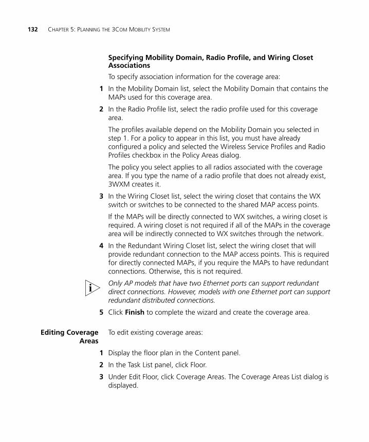
132 CHAPTER 5: PLANNING THE 3COM MOBILITY SYSTEM
Specifying Mobility Domain, Radio Profile, and Wiring Closet Associations
To specify association information for the coverage area:
1 In the Mobility Domain list, select the Mobility Domain that contains the MAPs used for this coverage area.
2 In the Radio Profile list, select the radio profile used for this coverage area.
The profiles available depend on the Mobility Domain you selected in step 1. For a policy to appear in this list, you must have already configured a policy and selected the Wireless Service Profiles and Radio Profiles checkbox in the Policy Areas dialog.
The policy you select applies to all radios associated with the coverage area. If you type the name of a radio profile that does not already exist, 3WXM creates it.
3 In the Wiring Closet list, select the wiring closet that contains the WX switch or switches to be connected to the shared MAP access points.
If the MAPs will be directly connected to WX switches, a wiring closet is required. A wiring closet is not required if all of the MAPs in the coverage area will be indirectly connected to WX switches through the network.
4 In the Redundant Wiring Closet list, select the wiring closet that will provide redundant connection to the MAP access points. This is required for directly connected MAPs, if you require the MAPs to have redundant connections. Otherwise, this is not required.
Only AP models that have two Ethernet ports can support redundant direct connections. However, models with one Ethernet port can support redundant distributed connections.
5 Click Finish to complete the wizard and create the coverage area.
Editing CoverageAreas
To edit existing coverage areas:
1 Display the floor plan in the Content panel.
2 In the Task List panel, click Floor.
3 Under Edit Floor, click Coverage Areas. The Coverage Areas List dialog is displayed.
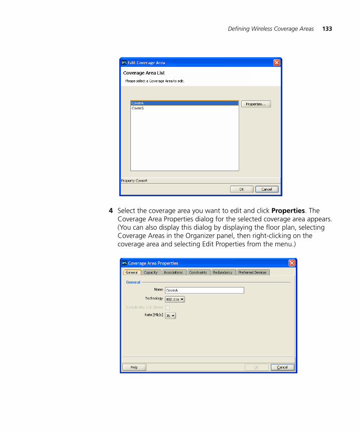
Defining Wireless Coverage Areas 133
4 Select the coverage area you want to edit and click Properties. The Coverage Area Properties dialog for the selected coverage area appears. (You can also display this dialog by displaying the floor plan, selecting Coverage Areas in the Organizer panel, then right-clicking on the coverage area and selecting Edit Properties from the menu.)
134 CHAPTER 5: PLANNING THE 3COM MOBILITY SYSTEM
5 Under the General tab, you can do the following:
In the Name box, edit the name of the coverage area (1 to 60 characters long, with no tabs).
In the Technology list, select one of the following:
802.11a
802.11b
802.11g
802.11a and 802.11b
802.11a and 802.11g
Select 802.11a and 802.11b if the area requires 802.11a and 802.11b coverage. Select 802.11a and 802.11g if the area requires 802.11a and 802.11g coverage.
For 802.11g, to prevent the association of 802.11b clients to any radio in this coverage area, select Exclude 802.11b clients. To allow 802.11b clients to associate to radios in the coverage area, clear Exclude 802.11b clients.
In the Rate [Mb/s] list, select the average desired association rate for typical clients in this coverage area.
6 Under the Capacity tab, you can do the following:
To calculate MAP placement and configuration based on coverage and on capacity for data, enable Use Capacity Calculation for Data.
In the Per Station Throughput list, specify the throughput (combined transmit and receive) in kilobits per second (Kbps) for a station.
In the Expected Station Count list, specify the number of clients you expect to be in the coverage area.
In the Station Oversubscription Ratio list, select the ratio for the average transmit behavior of the stations.
The station oversubscription ratio is the ratio of active clients compared to total clients. For example, the ratio 5:1 indicates that, statistically, 20 percent of the clients are active at any given time.
To calculate MAP placement and configuration based on coverage and on capacity for voice over IP, enable Use Capacity Calculation for Voice.
In the Active Call Bandwidth list, specify the amount of bandwidth in kilobits per second (Kbps) that you expect for each call.
Defining Wireless Coverage Areas 135
In the Active Handsets per AP list, specify the number of voice over IP phones that you want each MAP to handle.
In the Expected Handset Count list, specify the number of voice over IP phones you expect to be in the coverage area.
In the Handset Oversubscription Ratio list, select the ratio for the average transmit behavior of the voice over IP phones.
The handset oversubscription ratio is the ratio of active handsets compared to total handsets. For example, the ratio 4:1 indicates that, statistically, 25 percent of the voice over IP phones are active at any given time.
7 Under the Associations tab, you can do the following:
In the Mobility Domain list, select the Mobility Domain that contains the MAPs used for this coverage area.
In the Radio Profile list, select the radio profile to be used for this coverage area.
All radio profile policies configured in the network plan are listed. In addition, a default policy is listed. If you select default, the default radio profile settings are applied to the coverage area. (For information about policies, see “Configuring and Applying Policies” on page 387.)
In the Shared Area list, select a coverage area that will share MAP access points with the one you are configuring.
If you selected two radio technologies when defining the coverage area, a shared area is automatically created.
In the Wiring Closet list, select the wiring closet that contains the WX switch or switches to be connected to the shared MAPs.
In the Redundant Wiring Closet list, select the wiring closet that will provide redundant connection to the MAPs. This is required for directly connected MAPs, if you require the MAPs to have redundant connections. Otherwise, this is not required.
In the Available Access Points box, select an available MAP, if one is configured, to use in the coverage area, then click Add to move the MAP to the Current Access Points box.
This assumes that the network plan already has a MAP and that the MAP is physically located within the area you are configuring. If you are planning a new installation, you do not need to specify a MAP to use.
136 CHAPTER 5: PLANNING THE 3COM MOBILITY SYSTEM
8 Under the Constraints tab, you can do the following:
To change the ceiling height, specify the new height in the Height of the Ceiling box.
To change the height where MAPs are mounted, specify the new mounting height in the AP Placement Height box.
To change the WX switch model, select the model from the WX Model list.
To change the default MAP model, select the model from the Default AP Model list.
To change the MAP connection type, select the type from the AP Connection Type list:
Direct—MAPs are directly attached to dedicated WX switch ports.
Distributed—MAPs can be indirectly attached through intermediate Layer 2 or Layer 3 devices.
Distributed (Auto)—MAPs can be indirectly attached through intermediate Layer 2 or Layer 3 devices. They receive their configuration automatically using a profile that assigns a Distributed MAP number and name to the MAP from among the unused valid MAP numbers available on the switch. The profile also configures the MAP with the MAP and radio parameter settings in the profile.
To allow locked MAP access points to be deleted when the Compute and Place function determines that they are no longer required, select Allow Deletion of Locked MAPs.
A locked MAP is a MAP that is already associated with the coverage area. For example, if you computed and placed MAPs in this coverage area on a previous occasion and you are now optimizing the plan, the MAPs are still associated with the coverage area.
To change the amount of power to reserve when calculating optimal power, type or select the number of dBm in the Reserved Tx Power Margin listbox. This is the number of dBm below the maximum power setting that you want 3WXM to reserve in case the power needs to be increased later.
9 Under the Redundancy tab, you can do the following:
To plan for redundant MAP connections to WX switches, select Compute Redundancy.
Placing Third-Party Access Points 137
To use the same WX switch for redundant connections, select Use the Same WX for Redundancy.
This option places both of a MAP’s wired connections on the same WX switch. For optimal resiliency, 3Com recommends the use of different WX switches for redundancy.
To change the MAP connection type for the redundant connection, select Direct or Distributed from the AP Connection Type list.
To change the number of redundant connections for the distributed connection type, type the number in the Redundancy Level box.
For direct connections, the redundancy level is always 1.
10 Under the Preferred Devices tab, you can do the following:
In the Available Devices box, select an available WX switch, if one is configured, to use in the coverage area, then click Add to move the WX switch to the Current Devices box.
This assumes that the network plan already has a WX switch defined. If you are planning a new installation, you do not need to specify a WX switch to use.
11 When you have finished editing the properties of the coverage area, click OK to exit the Coverage Area Properties dialog and OK again to exit the Coverage Area Selection dialog.
Placing Third-Party Access Points
If you have third-party access points in your network, you can place icons for them on your floor layout. You also can configure their radio attributes using 3WXM. The radio attributes are taken into consideration when 3WXM assigns channels to MAP access points.
If you add third-party access points while using the Configuration tool bar option, the access points are listed in RF Planning on the Objects to Place tab, from which you can move them to their locations on the floor plans. (See “Moving a Third-Party AP Icon to its Floor Location”.)
You also can add third-party access points in RF Planning. (See “Creating and Placing an Icon for a Third-Party Access Point”.)
138 CHAPTER 5: PLANNING THE 3COM MOBILITY SYSTEM
Moving a Third-PartyAP Icon to its Floor
Location
If you added a third-party access point while using the Configuration tool bar option, the access point is on the Objects to Place tab.
1 In RF Planning, navigate to the floor plan.
2 In the Organizer panel, click Objects to Place.
3 Select the icon or description of the AP.
4 On the floor plan, click on the location where you want to place the AP.
You must click in a coverage area.
3WXM removes the AP from the Objects to Place list and places an icon for it on the floor plan.
Creating and Placingan Icon for a
Third-Party AccessPoint
1 In RF Planning, navigate to the floor plan.
2 In the Task List panel, click Tools.
3 In the Coverage Area task group, under Wiring Closet/Misc, click the (Insert Third-Party AP) icon
4 On the floor plan, click where you want the third-party access point to be placed. The Create Third-Party AP wizard appears.
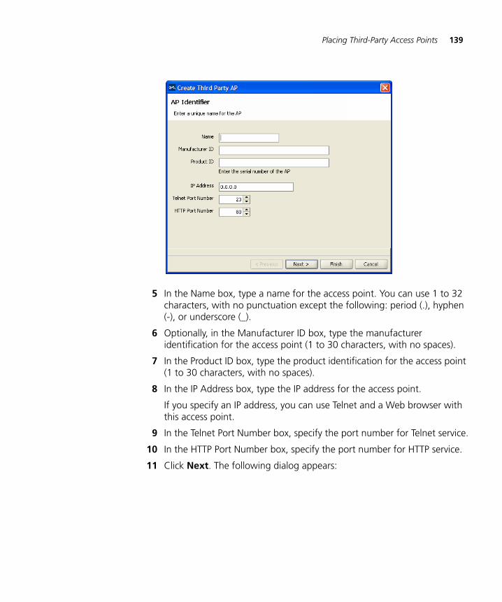
Placing Third-Party Access Points 139
5 In the Name box, type a name for the access point. You can use 1 to 32 characters, with no punctuation except the following: period (.), hyphen (-), or underscore (_).
6 Optionally, in the Manufacturer ID box, type the manufacturer identification for the access point (1 to 30 characters, with no spaces).
7 In the Product ID box, type the product identification for the access point (1 to 30 characters, with no spaces).
8 In the IP Address box, type the IP address for the access point.
If you specify an IP address, you can use Telnet and a Web browser with this access point.
9 In the Telnet Port Number box, specify the port number for Telnet service.
10 In the HTTP Port Number box, specify the port number for HTTP service.
11 Click Next. The following dialog appears:
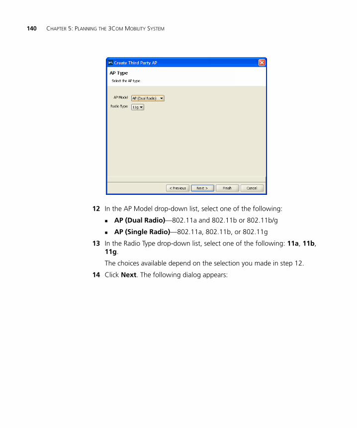
140 CHAPTER 5: PLANNING THE 3COM MOBILITY SYSTEM
12 In the AP Model drop-down list, select one of the following:
AP (Dual Radio)—802.11a and 802.11b or 802.11b/g
AP (Single Radio)—802.11a, 802.11b, or 802.11g
13 In the Radio Type drop-down list, select one of the following: 11a, 11b, 11g.
The choices available depend on the selection you made in step 12.
14 Click Next. The following dialog appears:
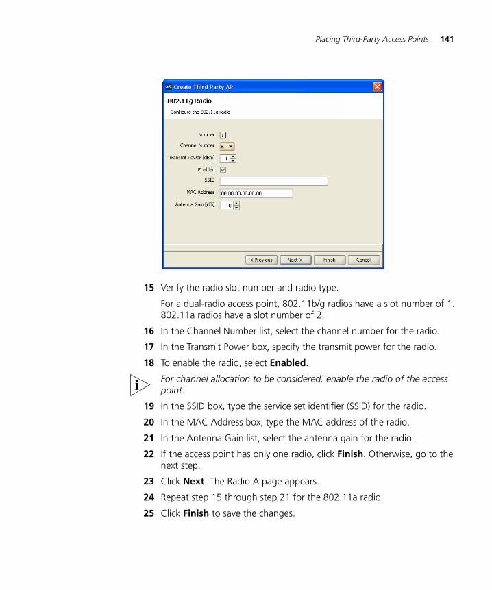
Placing Third-Party Access Points 141
15 Verify the radio slot number and radio type.
For a dual-radio access point, 802.11b/g radios have a slot number of 1. 802.11a radios have a slot number of 2.
16 In the Channel Number list, select the channel number for the radio.
17 In the Transmit Power box, specify the transmit power for the radio.
18 To enable the radio, select Enabled.
For channel allocation to be considered, enable the radio of the access point.
19 In the SSID box, type the service set identifier (SSID) for the radio.
20 In the MAC Address box, type the MAC address of the radio.
21 In the Antenna Gain list, select the antenna gain for the radio.
22 If the access point has only one radio, click Finish. Otherwise, go to the next step.
23 Click Next. The Radio A page appears.
24 Repeat step 15 through step 21 for the 802.11a radio.
25 Click Finish to save the changes.
142 CHAPTER 5: PLANNING THE 3COM MOBILITY SYSTEM
Placing Installed and Auto-Configured MAPs
You can place MAPs that are already installed on the floor into the network plan. To do this, you upload the WX configuration into 3WXM, associate the MAP with a coverage area, then place them on the floor plan.
In addition, MAPs that receive their configuration using a profile are automatically added to the network plan. They appear under Objects to Place in the Organizer panel. From the Objects to Place panel, you can place these MAPs onto the floor plan.
To place installed MAPs on the floor plan:
1 Select the Verification option in the main 3WXM tool bar, click the Network Verification tab, and upload the MAP configuration into 3WXM. (See “Verifying Configuration Changes” on page 377.)
2 Select the RF Planning option in the main 3WXM tool bar and display the floor plan in the Content panel.
3 In the Coverage Areas section, right-click on the coverage area for which the MAP is providing coverage, and select Edit Properties. The Coverage Area Properties dialog appears.
4 Click the Associations tab.
5 Select the MAP in the Available Access Points group box and click the Add button to move the MAP to the Current Access Points group box.
6 Click OK to save the changes and close the dialog box.
7 Click on Objects to Place in the Organizer panel.
8 Click on the MAP icon, then click on the location where you installed the MAP. The MAP icon moves from the Objects To Place panel to its location on the floor.
Computing MAP Placement 143
Computing MAP Placement
After providing information about floor plans, RF obstacles, and wireless coverage requirements, 3WXM can design the 3Com wireless network for this floor using the following process:
Compute and place MAPs (See “Computing and Placing MAP Access Points for a Coverage Area” on page 143.)
Assign channels to MAPs (See “Assigning MAP Channels” on page 151.)
Compute optimal power (See “Computing Optimal Power” on page 154.)
3WXM determines the number of MAPs that need to be installed in the area and the number of WX switches needed in the wiring closet (if the floor has them), and then places them on the floor plan. You can move the MAPs on the floor plan to more convenient locations to simplify installation. 3WXM also determines the WX to which a MAP should connect.
3WXM assigns transmit power levels and channels for each MAP. The power levels and association rates are set to optimize cell sizes for the coverage area. 3WXM shows the expected (simulated) coverage of the completed design, and allows you to see how the coverage changes when you make adjustments to MAP location or power levels.
Computing andPlacing MAP Access
Points for a CoverageArea
When you perform Compute and Place for one or more coverage areas, 3WXM automatically calculates the number of MAPs you require, based on coverage area information, and also places them in appropriate locations on the floor.
3WXM assumes that MAPs are mounted on the ceiling and takes the ceiling height into account when placing MAPs. 3WXM assumes that coverage is required down to 3 feet above the floor (the average height of a user’s desk). By default, 3WXM assumes that you want to directly connect the MAP access points to WX1200 switches and that you do not want redundant MAP connections for backup. You can change these design constraints.
By default, especially when you are performing Compute and Place for a coverage area for the first time, the results do not account for existing MAP access points. Manual overrides of the MAP results are not taken into account if you perform Compute and Place again.
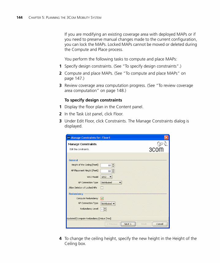
144 CHAPTER 5: PLANNING THE 3COM MOBILITY SYSTEM
If you are modifying an existing coverage area with deployed MAPs or if you need to preserve manual changes made to the current configuration, you can lock the MAPs. Locked MAPs cannot be moved or deleted during the Compute and Place process.
You perform the following tasks to compute and place MAPs:
1 Specify design constraints. (See “To specify design constraints”.)
2 Compute and place MAPs. (See “To compute and place MAPs” on page 147.)
3 Review coverage area computation progress. (See “To review coverage area computation” on page 148.)
To specify design constraints
1 Display the floor plan in the Content panel.
2 In the Task List panel, click Floor.
3 Under Edit Floor, click Constraints. The Manage Constraints dialog is displayed.
4 To change the ceiling height, specify the new height in the Height of the Ceiling box.
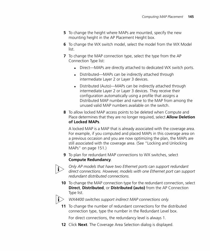
Computing MAP Placement 145
5 To change the height where MAPs are mounted, specify the new mounting height in the AP Placement Height box.
6 To change the WX switch model, select the model from the WX Model list.
7 To change the MAP connection type, select the type from the AP Connection Type list:
Direct—MAPs are directly attached to dedicated WX switch ports.
Distributed—MAPs can be indirectly attached through intermediate Layer 2 or Layer 3 devices.
Distributed (Auto)—MAPs can be indirectly attached through intermediate Layer 2 or Layer 3 devices. They receive their configuration automatically using a profile that assigns a Distributed MAP number and name to the MAP from among the unused valid MAP numbers available on the switch.
8 To allow locked MAP access points to be deleted when Compute and Place determines that they are no longer required, select Allow Deletion of Locked MAPs.
A locked MAP is a MAP that is already associated with the coverage area. For example, if you computed and placed MAPs in this coverage area on a previous occasion and you are now optimizing the plan, the MAPs are still associated with the coverage area. (See “Locking and Unlocking MAPs” on page 151.)
9 To plan for redundant MAP connections to WX switches, select Compute Redundancy.
Only AP models that have two Ethernet ports can support redundant direct connections. However, models with one Ethernet port can support redundant distributed connections.
10 To change the MAP connection type for the redundant connection, select Direct, Distributed, or Distributed (auto) from the AP Connection Type list.
WX4400 switches support indirect MAP connections only.
11 To change the number of redundant connections for the distributed connection type, type the number in the Redundant Level box.
For direct connections, the redundancy level is always 1.
12 Click Next. The Coverage Area Selection dialog is displayed.
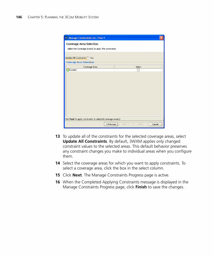
146 CHAPTER 5: PLANNING THE 3COM MOBILITY SYSTEM
13 To update all of the constraints for the selected coverage areas, select Update All Constraints. By default, 3WXM applies only changed constraint values to the selected areas. This default behavior preserves any constraint changes you make to individual areas when you configure them.
14 Select the coverage areas for which you want to apply constraints. To select a coverage area, click the box in the select column.
15 Click Next. The Manage Constraints Progress page is active.
16 When the Completed Applying Constraints message is displayed in the Manage Constraints Progress page, click Finish to save the changes.
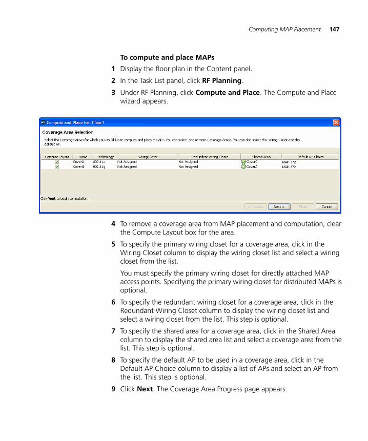
Computing MAP Placement 147
To compute and place MAPs
1 Display the floor plan in the Content panel.
2 In the Task List panel, click RF Planning.
3 Under RF Planning, click Compute and Place. The Compute and Place wizard appears.
4 To remove a coverage area from MAP placement and computation, clear the Compute Layout box for the area.
5 To specify the primary wiring closet for a coverage area, click in the Wiring Closet column to display the wiring closet list and select a wiring closet from the list.
You must specify the primary wiring closet for directly attached MAP access points. Specifying the primary wiring closet for distributed MAPs is optional.
6 To specify the redundant wiring closet for a coverage area, click in the Redundant Wiring Closet column to display the wiring closet list and select a wiring closet from the list. This step is optional.
7 To specify the shared area for a coverage area, click in the Shared Area column to display the shared area list and select a coverage area from the list. This step is optional.
8 To specify the default AP to be used in a coverage area, click in the Default AP Choice column to display a list of APs and select an AP from the list. This step is optional.
9 Click Next. The Coverage Area Progress page appears.
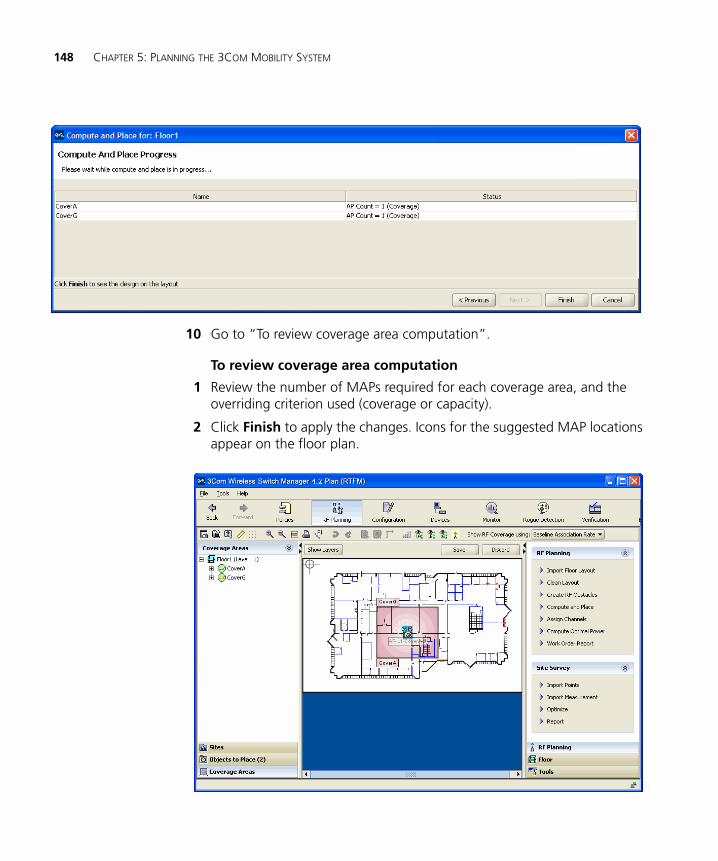
148 CHAPTER 5: PLANNING THE 3COM MOBILITY SYSTEM
10 Go to “To review coverage area computation”.
To review coverage area computation
1 Review the number of MAPs required for each coverage area, and the overriding criterion used (coverage or capacity).
2 Click Finish to apply the changes. Icons for the suggested MAP locations appear on the floor plan.
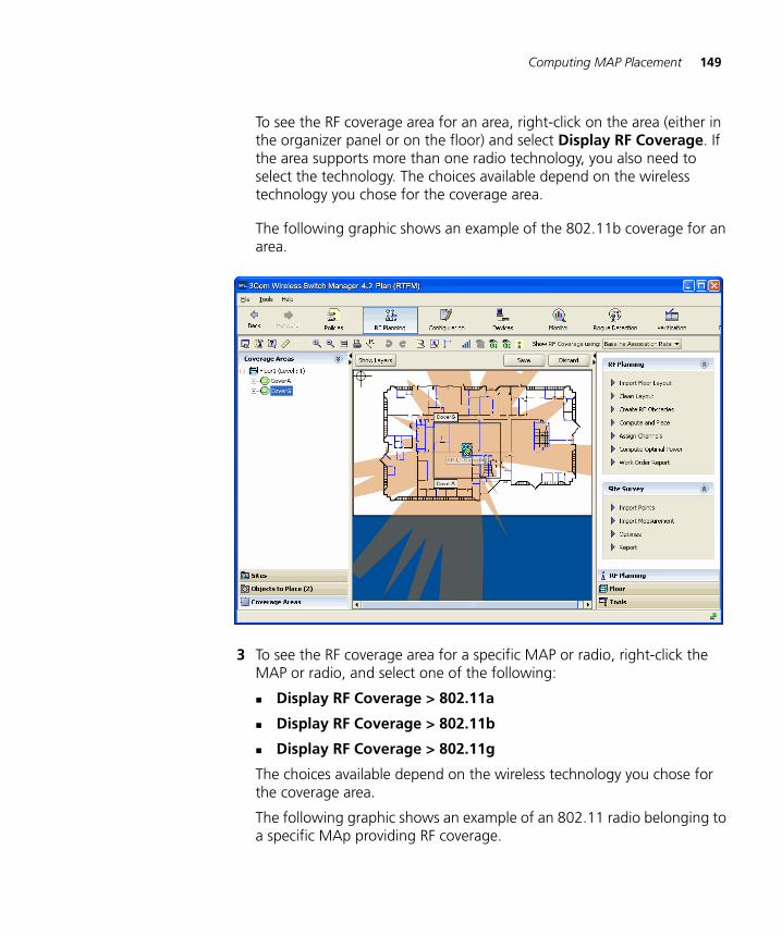
Computing MAP Placement 149
To see the RF coverage area for an area, right-click on the area (either in the organizer panel or on the floor) and select Display RF Coverage. If the area supports more than one radio technology, you also need to select the technology. The choices available depend on the wireless technology you chose for the coverage area.
The following graphic shows an example of the 802.11b coverage for an area.
3 To see the RF coverage area for a specific MAP or radio, right-click the MAP or radio, and select one of the following:
Display RF Coverage > 802.11a
Display RF Coverage > 802.11b
Display RF Coverage > 802.11g
The choices available depend on the wireless technology you chose for the coverage area.
The following graphic shows an example of an 802.11 radio belonging to a specific MAp providing RF coverage.
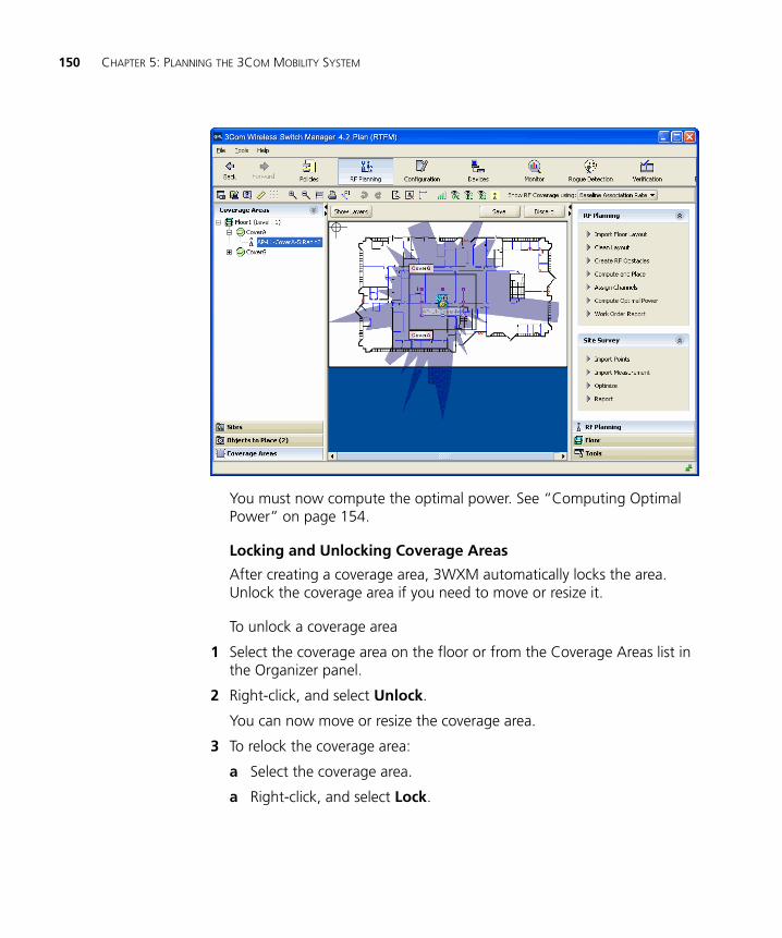
150 CHAPTER 5: PLANNING THE 3COM MOBILITY SYSTEM
You must now compute the optimal power. See “Computing Optimal Power” on page 154.
Locking and Unlocking Coverage Areas
After creating a coverage area, 3WXM automatically locks the area. Unlock the coverage area if you need to move or resize it.
To unlock a coverage area
1 Select the coverage area on the floor or from the Coverage Areas list in the Organizer panel.
2 Right-click, and select Unlock.
You can now move or resize the coverage area.
3 To relock the coverage area:
a Select the coverage area.
a Right-click, and select Lock.
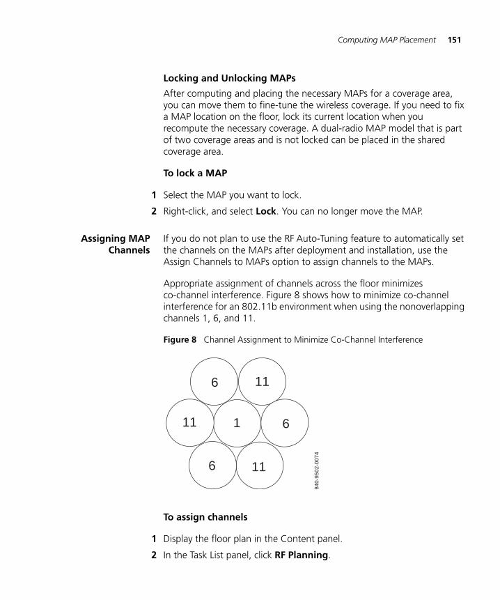
Computing MAP Placement 151
Locking and Unlocking MAPs
After computing and placing the necessary MAPs for a coverage area, you can move them to fine-tune the wireless coverage. If you need to fix a MAP location on the floor, lock its current location when you recompute the necessary coverage. A dual-radio MAP model that is part of two coverage areas and is not locked can be placed in the shared coverage area.
To lock a MAP
1 Select the MAP you want to lock.
2 Right-click, and select Lock. You can no longer move the MAP.
Assigning MAPChannels
If you do not plan to use the RF Auto-Tuning feature to automatically set the channels on the MAPs after deployment and installation, use the Assign Channels to MAPs option to assign channels to the MAPs.
Appropriate assignment of channels across the floor minimizes co-channel interference. Figure 8 shows how to minimize co-channel interference for an 802.11b environment when using the nonoverlapping channels 1, 6, and 11.
Figure 8 Channel Assignment to Minimize Co-Channel Interference
To assign channels
1 Display the floor plan in the Content panel.
2 In the Task List panel, click RF Planning.
6
6
6
840-
9502
-007
4
1
11
11
11
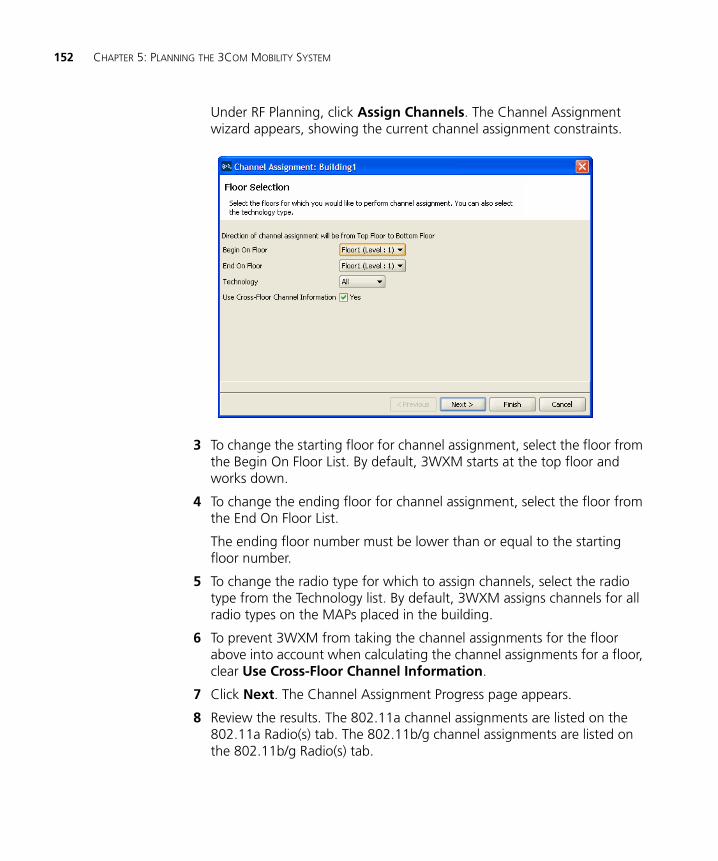
152 CHAPTER 5: PLANNING THE 3COM MOBILITY SYSTEM
Under RF Planning, click Assign Channels. The Channel Assignment wizard appears, showing the current channel assignment constraints.
3 To change the starting floor for channel assignment, select the floor from the Begin On Floor List. By default, 3WXM starts at the top floor and works down.
4 To change the ending floor for channel assignment, select the floor from the End On Floor List.
The ending floor number must be lower than or equal to the starting floor number.
5 To change the radio type for which to assign channels, select the radio type from the Technology list. By default, 3WXM assigns channels for all radio types on the MAPs placed in the building.
6 To prevent 3WXM from taking the channel assignments for the floor above into account when calculating the channel assignments for a floor, clear Use Cross-Floor Channel Information.
7 Click Next. The Channel Assignment Progress page appears.
8 Review the results. The 802.11a channel assignments are listed on the 802.11a Radio(s) tab. The 802.11b/g channel assignments are listed on the 802.11b/g Radio(s) tab.
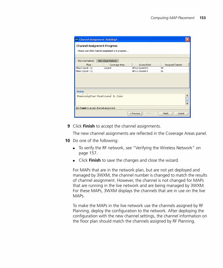
Computing MAP Placement 153
9 Click Finish to accept the channel assignments.
The new channel assignments are reflected in the Coverage Areas panel.
10 Do one of the following:
To verify the RF network, see “Verifying the Wireless Network” on page 157.
Click Finish to save the changes and close the wizard.
For MAPs that are in the network plan, but are not yet deployed and managed by 3WXM, the channel number is changed to match the results of channel assignment. However, the channel is not changed for MAPs that are running in the live network and are being managed by 3WXM. For these MAPs, 3WXM displays the channels that are in use on the live MAPs.
To make the MAPs in the live network use the channels assigned by RF Planning, deploy the configuration to the network. After deploying the configuration with the new channel settings, the channel information on the floor plan should match the channels assigned by RF Planning.
154 CHAPTER 5: PLANNING THE 3COM MOBILITY SYSTEM
The MAPs on a floor plan in RF Planning are color coded to indicate their monitored status:
Green—Up
Yellow—Up (but with minor service degradation)
Orange—Up (but with major service degradation)
Red—Down
Blue—Unknown
A MAP with a blue background is not in the live network even though it is on the floor plan. The channel number for this MAP will match the channel number assigned by RF Planning. However, a MAP with a green background is running in the live network, and the channel number of this MAP will indicate the channel on which the MAP is operating, which is not necessarily the channel assigned by RF Planning.
If RF Auto-Tuning of channels is enabled, the channels can change on live MAPs even if you do not change them.
Computing OptimalPower
If you do not plan to use the RF Auto-Tuning feature to automatically set the power levels on the MAPs after deployment and installation, use the Compute Optimal Power option to calculate the power settings for the MAPs.
Transmit power levels must be high enough to adequately cover an area, but also low enough to minimize co-channel interference. 3WXM factors in these considerations when calculating optimal power.
3Com recommends that you assign channels before you compute optimal power, to ensure successful power computation.
If the MAP is using an external antenna, specify the antenna model and the coverage direction of the antenna before computing power. See step 8 in “Configuring Advanced MAP Settings” on page 289.
To compute optimal power
1 In the Task List panel, click RF Planning.
2 Under RF Planning, click Compute Optimal Power.
The Compute Power For wizard appears, showing a list of the areas you defined and the corresponding technology.
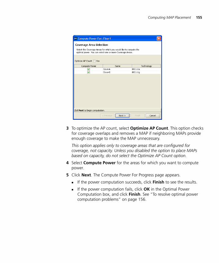
Computing MAP Placement 155
3 To optimize the AP count, select Optimize AP Count. This option checks for coverage overlaps and removes a MAP if neighboring MAPs provide enough coverage to make the MAP unnecessary.
This option applies only to coverage areas that are configured for coverage, not capacity. Unless you disabled the option to place MAPs based on capacity, do not select the Optimize AP Count option.
4 Select Compute Power for the areas for which you want to compute power.
5 Click Next. The Compute Power For Progress page appears.
If the power computation succeeds, click Finish to see the results.
If the power computation fails, click OK in the Optimal Power Computation box, and click Finish. See “To resolve optimal power computation problems” on page 156.
156 CHAPTER 5: PLANNING THE 3COM MOBILITY SYSTEM
To resolve optimal power computation problems
If power levels for one or more coverage areas could not be optimized, show the RF coverage at baseline association and minimum transmit rates for the coverage areas by doing the following:
1 In the Show RF coverage using listbox, select how you want to display the coverage:
Baseline Association Rate—Coverage is shown based on the MAP radio baseline association rate. The baseline association rate is the typical data rate the radio is expected to support for client associations. (The baseline association rate is specified during planning, on a coverage area basis.)
Data Rate—Coverage is shown in colored bands that represent each of the data transmit rates supported by the radio. These rates are standard for each radio type.
RSSI—Coverage is shown based on the received signal strength indication (RSSI) heard by other radios.
2 In the Coverage Areas section of the Organizer panel, select the scope for which you want to display coverage. You can display coverage for an individual radio, a specific coverage area, or all coverage areas on the floor.
To select multiple contiguous objects, click Shift while selecting.
To select multiple noncontiguous objects, click Ctrl while selecting.
If you need to make adjustments, do the following:
a Manually move the MAPs, or increase the transmit power levels.
b Manually create more MAPs, and place them on the floor.
c Modify the coverage area so that the capacity requirements are higher.
If you manually add MAPs to a coverage area, they might be moved or removed the next time you perform Compute and Place.
Verifying the Wireless Network 157
Verifying the Wireless Network
You can use the following tools to help verify the wireless network:
Show RF coverage.
Place RF measurement points.
Use RF interactive measurement mode.
Showing RF Coverage Looking at the RF coverage allows you to see if the entire area is adequately covered by the MAPs. You can move the MAPs and see how the coverage changes.
You can see the RF coverage for an area by doing the following:
1 In the Coverage Areas section of the Organizer panel, select the coverage area.
2 Right-click, and select Display RF Coverage.
This procedure displays coverage provided by the access points on a single floor. To also view coverage provided to the current floor from access points on the floor above or below, do the following.
3 In the Coverage Areas section of the Organizer panel, navigate to the floor.
4 Expand the floor to display its coverage areas.
5 Right-click on a coverage area, and select DIsplay RF Coverage.
If the coverage area provided by an access point on the floor above or below is one meter or less, 3WXM displays a message. This coverage area is not displayed on the current floor plan.
Resolving coverage gaps
You might see small “holes” when looking at the coverage areas at the baseline association rate. These small holes are most likely areas where users still have wireless access but not at the baseline association rate. In most situations, increasing transmit power levels to close the holes will generate more co-channel interference. 3Com recommends that you allow these small holes during the planning process.
If you need to resolve the gaps in coverage, try the following:
1 Select the coverage area.
2 Right-click, and select Display RF Coverage.
158 CHAPTER 5: PLANNING THE 3COM MOBILITY SYSTEM
3 In the Display RF coverage using listbox, select how you want to display the coverage:
Baseline Association Rate—Coverage is shown based on the MAP radio baseline association rate. The baseline association rate is the typical data rate the radio is expected to support for client associations. (The baseline association rate is specified during planning, on a coverage area basis.)
Data Rate—Coverage is shown in colored bands that represent each of the data transmit rates supported by the radio. These rates are standard for each radio type.
RSSI—Coverage is shown based on the received signal strength indication (RSSI) heard by other radios.
If you need to make adjustments, do the following:
1 Move the MAPs, or increase the transmit power levels to provide better coverage.
2 Create more MAPs, and place them on the floor.
3 Modify the coverage area so that the capacity requirements are higher.
If you manually add MAPs to a coverage area, they might be moved or removed when you next perform Compute and Place.
If you have already installed a MAP in the network and you want to add it to the coverage area, see “Adding New MAPs that Are Already Installed to the Network Plan” on page 490.
Placing RFMeasurement Points
An RF measurement point on the floor plan simulates the measurement of signal strength from all MAPs at a specific position on the floor. Placing RF measurement points is optional. RF measurement points are helpful for verifying the wireless network. You can place as many RF measurement points as you want. You can place them anywhere and move them later. Information from RF measurement points is included in the work order of a floor.
To place an RF measurement point
1 Display the floor plan in the Content panel.
2 In the Task List panel, click Tools.
3 In the Coverage Area task group, under Wiring Closet/Misc, click the (Insert Measurement Point) icon.
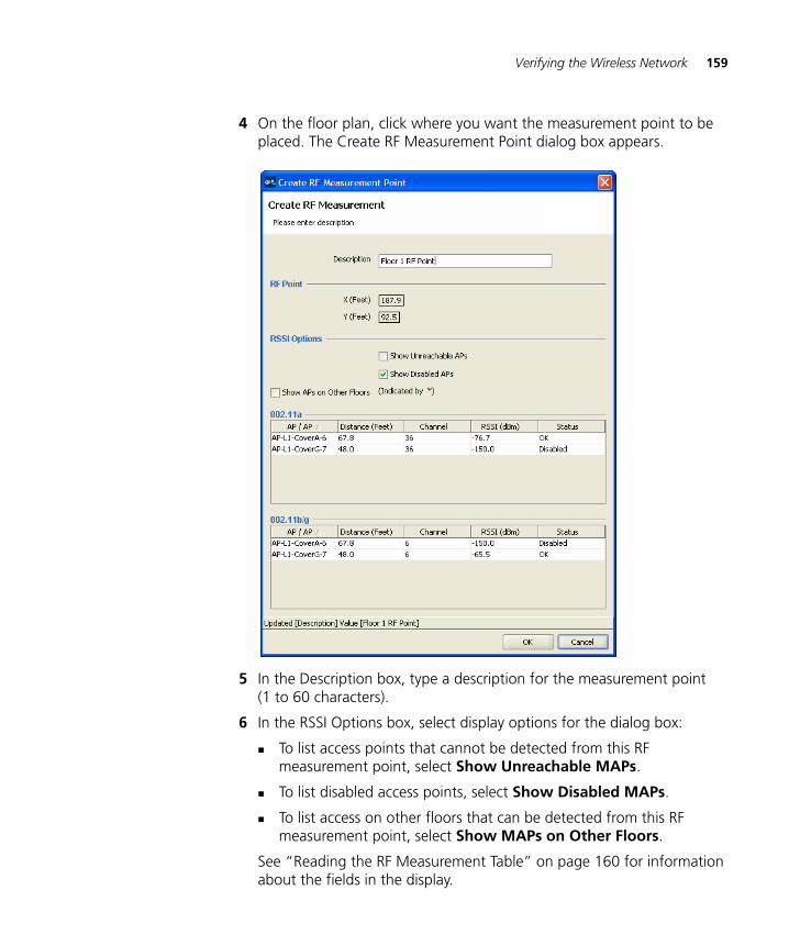
Verifying the Wireless Network 159
4 On the floor plan, click where you want the measurement point to be placed. The Create RF Measurement Point dialog box appears.
5 In the Description box, type a description for the measurement point (1 to 60 characters).
6 In the RSSI Options box, select display options for the dialog box:
To list access points that cannot be detected from this RF measurement point, select Show Unreachable MAPs.
To list disabled access points, select Show Disabled MAPs.
To list access on other floors that can be detected from this RF measurement point, select Show MAPs on Other Floors.
See “Reading the RF Measurement Table” on page 160 for information about the fields in the display.
160 CHAPTER 5: PLANNING THE 3COM MOBILITY SYSTEM
7 Click OK to save the changes and close the box.
8 Do one of the following:
To use the RF interactive measurement mode, see “Using RF Interactive Measurement Mode”.
To generate network design information, see “Generating RF Network Design Information” on page 162.
Click Finish to save the changes and close the wizard.
Using RF InteractiveMeasurement Mode
RF interactive measurement mode is useful when you are troubleshooting or surveying the coverage areas on the floor. You can quickly measure signal strengths for any location on the floor.
To use the RF interactive measurement mode
1 Click the icon in the toolbar.
2 Click any location on the floor. Received signal strength indication (RSSI) measurements for the selected location appear next to the Floor View. See “Reading the RF Measurement Table” for information about the fields in the display.
Reading the RFMeasurement Table
The projected signal strengths for the planned equipment from that measurement point are shown in the RF measurement table.
X-Y coordinates for the measurement point and display options are also available to customize the RSSI table. Using this interactive mode can be valuable when verifying deployment coverage with a portable WLAN measurement tool on the floor.
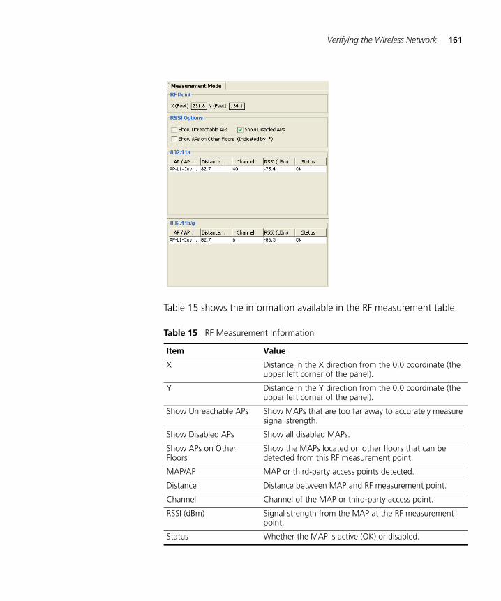
Verifying the Wireless Network 161
Table 15 shows the information available in the RF measurement table.
Table 15 RF Measurement Information
Item Value
X Distance in the X direction from the 0,0 coordinate (the upper left corner of the panel).
Y Distance in the Y direction from the 0,0 coordinate (the upper left corner of the panel).
Show Unreachable APs Show MAPs that are too far away to accurately measure signal strength.
Show Disabled APs Show all disabled MAPs.
Show APs on Other Floors
Show the MAPs located on other floors that can be detected from this RF measurement point.
MAP/AP MAP or third-party access points detected.
Distance Distance between MAP and RF measurement point.
Channel Channel of the MAP or third-party access point.
RSSI (dBm) Signal strength from the MAP at the RF measurement point.
Status Whether the MAP is active (OK) or disabled.
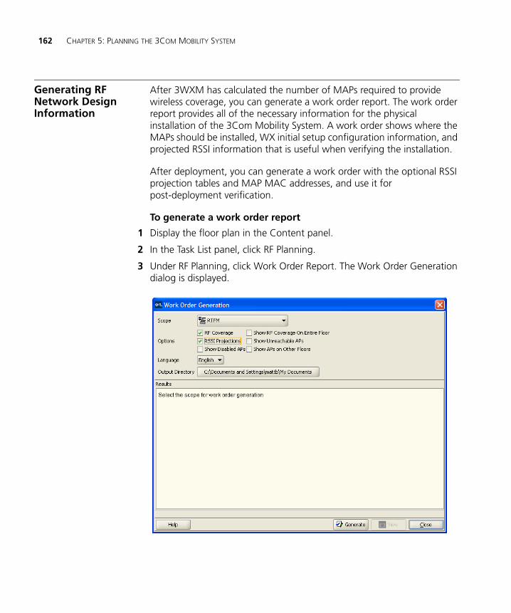
162 CHAPTER 5: PLANNING THE 3COM MOBILITY SYSTEM
Generating RF Network Design Information
After 3WXM has calculated the number of MAPs required to provide wireless coverage, you can generate a work order report. The work order report provides all of the necessary information for the physical installation of the 3Com Mobility System. A work order shows where the MAPs should be installed, WX initial setup configuration information, and projected RSSI information that is useful when verifying the installation.
After deployment, you can generate a work order with the optional RSSI projection tables and MAP MAC addresses, and use it for post-deployment verification.
To generate a work order report
1 Display the floor plan in the Content panel.
2 In the Task List panel, click RF Planning.
3 Under RF Planning, click Work Order Report. The Work Order Generation dialog is displayed.
Generating RF Network Design Information 163
4 Specify whether to include the following information in the work order:
RF Coverage
RSSI Projections
Display Disabled MAPs (only available if RSSI Projections is selected)
Display RF Coverage On Entire Floor (only available if RSSI Projections is selected)
Show Unreachable MAPs (only available if RSSI Projections is Display)
Display MAPs on Other Floors (only available if RSSI Projections is selected)
5 In the Language list, select English or German.
The language you select is the language used when you next access this page.
6 To select the directory to which the inventory report is saved, click Choose. The Select dialog box appears.
7 Navigate to the directory you want, and click Select.
3WXM uses this directory when generating subsequent reports.
8 Click Generate Work Order.
The work order is saved in the directory you specified in the format WO_scope_name_date. If you generate another order for the same scope on the same day, the old work order is overwritten.
When the work order has been generated, the View button becomes available.
9 Click View. A browser window opens to display the work order in HTML format.
A browser must be specified in the Tools tab in the Preferences dialog box (Tools > Preferences).
10 Select a floor from the Select Floor list and click View Work Order. The work order is displayed starting at the floor you specified. You can scroll to view additional information.
11 Click Close to close the dialog.

164 CHAPTER 5: PLANNING THE 3COM MOBILITY SYSTEM
6 CONFIGURING WX SYSTEM PARAMETERS
This chapter and chapters 7 and 8 describe how to view and configure WX switches using 3WXM.
If you want to use 3WXM planning to configure switches for you as part of coverage planning, see “Planning the 3Com Mobility System” on page 75.
If you are planning to use 3WXM to configure switches in a remote office, see “Configuring WX Switches Remotely” on page 345.
WX Switch Configuration Objects
Configuration objects for WX switches are organized into the following categories:
System
Wireless
AAA
You can access configuration wizards for these object types by clicking on tasks in the Task List panel, or by selecting the object type under a WX switch in the Organizer panel.
Table 16 lists the WX switch object types.
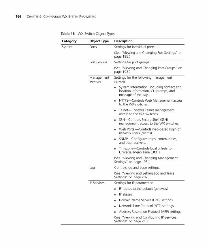
166 CHAPTER 6: CONFIGURING WX SYSTEM PARAMETERS
Table 16 WX Switch Object Types
Category Object Type Description
System Ports Settings for individual ports.
(See “Viewing and Changing Port Settings” on page 185.)
Port Groups Settings for port groups.
(See “Viewing and Changing Port Groups” on page 193.)
Management Services
Settings for the following management services:
System Information, including contact and location information, CLI prompt, and message of the day.
HTTPS—Controls Web Management access to the WX switches.
Telnet—Controls Telnet management access to the WX switches.
SSH—Controls Secure Shell (SSH) management access to the WX switches.
Web Portal—Controls web-based login of network users (clients).
SNMP—Configures traps, communities, and trap receivers.
Timezone—Controls local offsets to Universal Mean Time (UMT).
(See “Viewing and Changing Management Settings” on page 195.)
Log Controls log and trace settings.
(See “Viewing and Setting Log and Trace Settings” on page 207.)
IP Services Settings for IP parameters:
IP routes to the default (gateway)
IP aliases
Domain Name Service (DNS) settings
Network Time Protocol (NTP) settings
Address Resolution Protocol (ARP) settings
(See “Viewing and Configuring IP Services Settings” on page 210.)
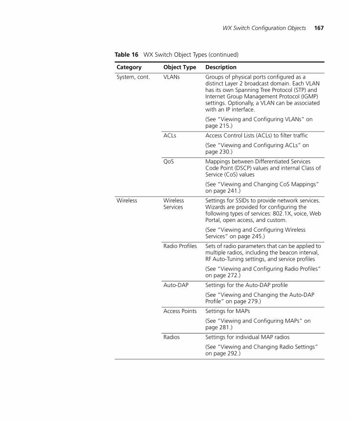
WX Switch Configuration Objects 167
System, cont. VLANs Groups of physical ports configured as a distinct Layer 2 broadcast domain. Each VLAN has its own Spanning Tree Protocol (STP) and Internet Group Management Protocol (IGMP) settings. Optionally, a VLAN can be associated with an IP interface.
(See “Viewing and Configuring VLANs” on page 215.)
ACLs Access Control Lists (ACLs) to filter traffic
(See “Viewing and Configuring ACLs” on page 230.)
QoS Mappings between Differentiated Services Code Point (DSCP) values and internal Class of Service (CoS) values
(See “Viewing and Changing CoS Mappings” on page 241.)
Wireless Wireless Services
Settings for SSIDs to provide network services. Wizards are provided for configuring the following types of services: 802.1X, voice, Web Portal, open access, and custom.
(See “Viewing and Configuring Wireless Services” on page 245.)
Radio Profiles Sets of radio parameters that can be applied to multiple radios, including the beacon interval, RF Auto-Tuning settings, and service profiles
(See “Viewing and Configuring Radio Profiles” on page 272.)
Auto-DAP Settings for the Auto-DAP profile
(See “Viewing and Changing the Auto-DAP Profile” on page 279.)
Access Points Settings for MAPs
(See “Viewing and Configuring MAPs” on page 281.)
Radios Settings for individual MAP radios
(See “Viewing and Changing Radio Settings” on page 292.)
Table 16 WX Switch Object Types (continued)
Category Object Type Description
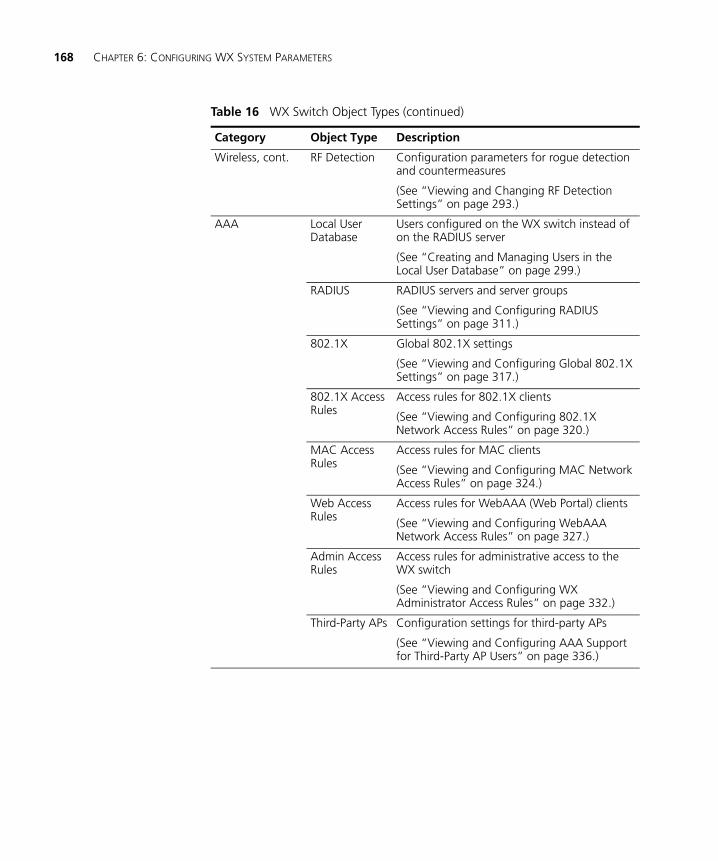
168 CHAPTER 6: CONFIGURING WX SYSTEM PARAMETERS
Wireless, cont. RF Detection Configuration parameters for rogue detection and countermeasures
(See “Viewing and Changing RF Detection Settings” on page 293.)
AAA Local User Database
Users configured on the WX switch instead of on the RADIUS server
(See “Creating and Managing Users in the Local User Database” on page 299.)
RADIUS RADIUS servers and server groups
(See “Viewing and Configuring RADIUS Settings” on page 311.)
802.1X Global 802.1X settings
(See “Viewing and Configuring Global 802.1X Settings” on page 317.)
802.1X Access Rules
Access rules for 802.1X clients
(See “Viewing and Configuring 802.1X Network Access Rules” on page 320.)
MAC Access Rules
Access rules for MAC clients
(See “Viewing and Configuring MAC Network Access Rules” on page 324.)
Web Access Rules
Access rules for WebAAA (Web Portal) clients
(See “Viewing and Configuring WebAAA Network Access Rules” on page 327.)
Admin Access Rules
Access rules for administrative access to the WX switch
(See “Viewing and Configuring WX Administrator Access Rules” on page 332.)
Third-Party APs Configuration settings for third-party APs
(See “Viewing and Configuring AAA Support for Third-Party AP Users” on page 336.)
Table 16 WX Switch Object Types (continued)
Category Object Type Description
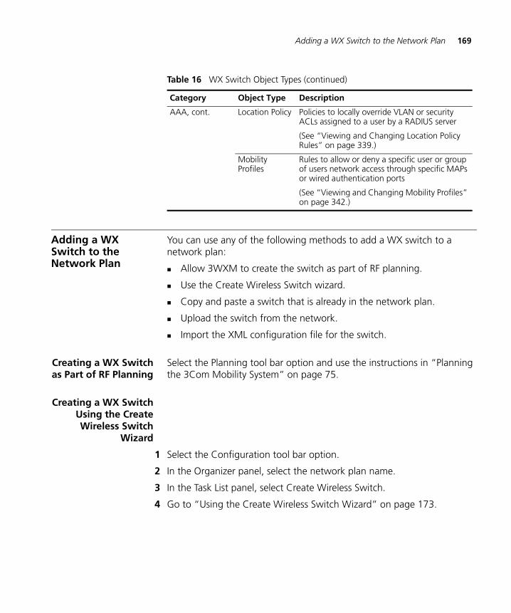
Adding a WX Switch to the Network Plan 169
Adding a WX Switch to the Network Plan
You can use any of the following methods to add a WX switch to a network plan:
Allow 3WXM to create the switch as part of RF planning.
Use the Create Wireless Switch wizard.
Copy and paste a switch that is already in the network plan.
Upload the switch from the network.
Import the XML configuration file for the switch.
Creating a WX Switchas Part of RF Planning
Select the Planning tool bar option and use the instructions in “Planning the 3Com Mobility System” on page 75.
Creating a WX SwitchUsing the CreateWireless Switch
Wizard
1 Select the Configuration tool bar option.
2 In the Organizer panel, select the network plan name.
3 In the Task List panel, select Create Wireless Switch.
4 Go to “Using the Create Wireless Switch Wizard” on page 173.
AAA, cont. Location Policy Policies to locally override VLAN or security ACLs assigned to a user by a RADIUS server
(See “Viewing and Changing Location Policy Rules” on page 339.)
Mobility Profiles
Rules to allow or deny a specific user or group of users network access through specific MAPs or wired authentication ports
(See “Viewing and Changing Mobility Profiles” on page 342.)
Table 16 WX Switch Object Types (continued)
Category Object Type Description
170 CHAPTER 6: CONFIGURING WX SYSTEM PARAMETERS
Creating a New WXSwitch Based on a
Configured Switch inthe Network Plan
You can copy and modify a switch that is already in the network plan, by copying and pasting the switch in the Organizer panel.
1 Select the Configuration tool bar option.
2 In the Organizer panel, select the switch you want to copy, then right-click on the switch and select Copy.
3 Right-click and select Paste. The Wireless Switch Properties wizard appears.
4 In the WX Name box, type the name of the WX switch (1 to 256 alphanumeric characters, with no spaces or tabs).
Within a network plan (and all Mobility Domains), each WX must have a unique name.
5 Type the serial number for the switch in the Serial Number box.
6 To modify the system IP address and VLAN, select them from the System VLAN/IP drop-down list.
The system IP address determines the interface or source IP address MSS uses for system tasks, including the following:
Mobility Domain operations
Topology reporting for dual-homed MAP access points
Default source IP address used in unsolicited communications such as AAA accounting reports and SNMP notifications
7 Click Management Interface.
8 To enable the switch to be managed by 3WXM, select Managed. Until this option is selected, you cannot deploy the switch configuration you create in 3WXM to the actual switch in the network.
This option also enables the Launch Telnet and Launch Browser options in the Task List panel.
CAUTION: After selecting Managed to enable management of the switch by 3WXM, do not change this option unless advised to do so by 3Com Technical Support. If you change a WX switch to an unmanaged state in a network plan, all network operations (polling) stop for that WX switch. If you change back to a managed state, the entire configuration of the switch is replaced with the settings from the network plan, which can result in loss of connectivity to the switch.
Adding a WX Switch to the Network Plan 171
9 To modify the management interface, select the IP interface and VLAN from the VLAN/IP drop-down list.
10 To modify the enable password, edit the string in the Enable Password box.
Use this option when you are creating a new switch in 3WXM. This option modifies the password in the network plan. However, if the switch is already deployed in the network, 3WXM cannot apply configuration changes to the switch unless the enable password in 3WXM matches the enable password already configured on the switch.
11 Click WX Associations.
12 To change the Mobility Domain membership for the switch, select the Mobility Domain from the Mobility Domain drop-down list.
To leave the switch out of all Mobility Domains, select Not Assigned.
13 To change the wiring closet membership for the switch, select the closet from the Wiring Closet drop-down list.
To leave the switch out of all wiring closets, select Not Assigned.
14 Click OK to save the changes and close the wizard.
15 Edit other parameters as required. (See the rest of this chapter and the following two chapters.)
Adding a Switch byUploading its
Configuration fromthe Network
If you have already deployed a WX switch in the network and want to add the switch to the network plan, upload the configuration for the switch into 3WXM, edit the switch, then redeploy the switch with the new parameters. (See “Uploading a WX Switch into the Network Plan” on page 71.)
Adding a Switch byImporting a
Configuration File
You can add a switch to the network plan by importing a switch configuration file. The configuration is imported in XML format.
1 Use the procedure in “Importing and Exporting Switch Configuration Files” on page 374 to import the configuration file for the switch.
2 In the Organizer panel, click the plus sign next to the new WX switch to expand the configuration options.
3 Select a configuration option, then use the instructions in this chapter or one of the following chapters to modify the configuration information:
Chapter 7, “Configuring Wireless Parameters” on page 245
Chapter 8, “Configuring Authentication, Authorization, and Accounting Parameters” on page 299
172 CHAPTER 6: CONFIGURING WX SYSTEM PARAMETERS
Configuring Basic and Advanced Settings
Clicking on an option in the Task List panel opens a configuration wizard. Configuration wizards enable the configuration of basic settings for an object. After configuring the settings and close the wizard, the new object is added to a table in the Content panel for most types of WX switch objects.
Some objects have advanced, infrequently modified settings that are not configurable using the wizard. To configure advanced settings for an object listed in a table in the Content panel, select the object, then click Properties. The Properties button opens a configuration dialog containing all configurable settings for the object, including the advanced settings.
For simple changes, select multiple objects and click Properties to make the change for all of the selected objects. For example, to disable or reenable multiple ports, select all of the ports, click Properties, change the port state in the dialog, and then close the dialog. The changes take effect on of all the selected ports.
Reviewing and Deploying Changes
3WXM does not automatically deploy switch configuration changes from the network plan to the actual switches in the network. The following options in the Task List panel allow you to review and deploy changes:
Review—Displays a categorized list of the undeployed changes.
Deploy—Sends the changes to the network.
Reviewing Changes Click Review to review undeployed configuration changes. Changes are listed by feature category. To hide or redisplay a category, click on the double arrow next to the category name.
A plus sign next to a configuration item indicates there are multiple changes for that item. Click the plus sign to display the individual changes.
To print the list of changes, click Print.
Deploying Changes To deploy all of the changes, click Deploy. 3WXM compares the changes to the verification rules, and lists any warnings or error messages. If there are any errors, 3WXM will not deploy the changes. To deploy the changes, you must first resolve the errors. To resolve configuration errors, use the Verification option.
Using the Create Wireless Switch Wizard 173
Using the Create Wireless Switch Wizard
1 Access the Create Wireless Switch wizard:
a Select the Configuration tool bar option.
b In the Organizer panel, select the network plan name.
c In the Task List panel, select the Wireless Switch task.
2 In the WX Name box, type the name of the WX switch (1 to 256 alphanumeric characters, with no spaces or tabs).
Within a network plan (and all Mobility Domains), each WX must have a unique name.
3 In the WX Model list, select the WX switch model.
4 In the Software Version list, select the version of Mobility System Software (MSS) you expect to run on the WX switch.
5 In the Enable Password box, type the enable password for the WX.
This password must match the enable password that was defined on the switch using the CLI command set enablepass. For more information, see the Wireless LAN Switch and Controller Configuration Guide.
The password is encrypted when you type it.
6 Click Next.
7 Enter the IP address and network mask in the IP Address field.
3WXM will assign this IP address to the default VLAN (VLAN 1).
8 Click Next.
9 In the Available Members list, select the ports to add to the default VLAN and click Add or Move.
The Add button adds the ports to the new VLAN without removing them from any other VLANs.
The Move button removes the ports from all other VLANs, and places them in the new VLAN.
The ports appear in the Current Members list.
10 To tag ports in the VLAN, select Tag and edit the tag value.
174 CHAPTER 6: CONFIGURING WX SYSTEM PARAMETERS
Use this option if you used the Add button instead of the Move button to place the ports in the VLAN. For a port to be a member of more than one VLAN, the port must be tagged. By default, ports are untagged. When you enable tagging, the default tag value is the same as the VLAN ID.
11 Click Next.
12 Enter the IP address to match the address of the default router for the default interface of the VLAN.
13 Click Next.
14 To place the switch in a Mobility Domain, select the Mobility Domain from the Mobility Domain drop-down list.
The Mobility Domain must already be created. (See “Defining a Mobility Domain” on page 64.) If you still need to create the Mobility Domain, finish creating the switch, then create the Mobility Domain.
Select the switch in the Organizer panel to display its basic settings in the Content panel, and select the Mobility Domain from the Mobility Domain drop-down list.
15 To place the switch in a wiring closet, select the closet from the Wiring Closet drop-down list.
The wiring closet must already be created on a floor plan. If you still need to create the wiring closet, finish creating the switch, then create the wiring closet. The Create Wiring Closet wizard in RF Planning enables you to create a wiring closet and add the switch to it. (See “Creating a Wiring Closet” on page 117.)
If you do not select the switch when you configure the wiring closet, select the switch in the Organizer panel to display its basic settings in the Content panel, and select the wiring closet from the Wiring Closet drop-down list.
16 Click Finish.
Setting Up a Switch 175
Setting Up a Switch After creating a switch, use the System Setup Wizard to configure the following essential operation and management parameters:
SNMP settings for monitoring of the switch by 3WXM
VLANs
RADIUS servers and server groups
Wireless services
Auto-DAP profile settings
The SNMP security level and enabled version configured with this wizard apply to all SNMP notification targets. However, the security model, community string, and access type apply only to the notification target 3WXM Services.
To set up a switch
1 Select the Configuration tool bar option.
2 In the Organizer panel, select the WX switch.
3 In the Task List panel, select System Setup.
The System Setup wizard appears.
4 Read the first page, then click Next.
5 Optionally, create a static route, or click Next to skip this step.
a Select a static route to edit or click Create to create one.
To configure a default route, select Default Route and go to step b.
Otherwise, in the Destination IP Address box, type the destination IP address and subnet mask in classless interdomain routing (CIDR) notation (for example, 10.10.0.0/16).
b In the Gateway box, type the IP address of the default router (gateway) that the route uses.
c In the Metric box, specify the cost for using the route (0 to 2,147,483,647). Lower-cost routes are preferred. The default is 1.
6 Click OK.
7 Configure SNMP settings:
176 CHAPTER 6: CONFIGURING WX SYSTEM PARAMETERS
a Select the minimum level of security to allow for any SNMP communication with the switch from the Security Level drop-down list:
Unsecured—SNMP message exchanges are not secure. This is the default, and is the only value supported for SNMPv1 and SNMPv2c. (This security level is the same as the noAuthNoPriv level described in SNMPv3 RFCs.)
Authenticated—SNMP message exchanges are authenticated but are not encrypted. (This security level is the same as the authNoPriv level described in SNMPv3 RFCs.)
Encrypted—SNMP message exchanges are authenticated and encrypted. (This security level is the same as the authPriv level described in SNMPv3 RFCs.)
AuthRequest-UnsecuredNotify—SNMP message exchanges are authenticated but are not encrypted, and notifications are neither authenticated nor encrypted.
The only security level supported for SNMPv1 and SNMPv2c is Unsecured. To use a higher security level, you must use USM (SNMPv3).
b Select the version(s) of SNMP you want the switch to run:
V1
V2c
USM (SNMPv3)
c Click Next.
d In the Security Model drop-down list, select the security model to use specifically for SNMP communications between the switch and 3WXM:
USM (SNMPv3)
V1
e If you selected USM, then select the minimum level of security for SNMP communication between the switch and 3WXM Services:
Unsecured—SNMP message exchanges are not secure. This is the default, and is the only value supported for SNMPv1 and SNMPv2c. (This security level is the same as the noAuthNoPriv level described in SNMPv3 RFCs.)
Setting Up a Switch 177
Authenticated—SNMP message exchanges are authenticated but are not encrypted. (This security level is the same as the authNoPriv level described in SNMPv3 RFCs.)
Encrypted—SNMP message exchanges are authenticated and encrypted. (This security level is the same as the authPriv level described in SNMPv3 RFCs.)
f Click Next.
g Type the USM name or community string name in the corresponding box.
h Select the access type from the Access Type drop-down list:
read-notify—An SNMP management application using the string can get object values on the switch but cannot set them. The switch can use the string to send notifications.
notify-only—The switch can use the string to send notifications.
read-write-notify—An SNMP management application using the string can get and set object values on the switch. The switch can use the string to send notifications.
i Click Next.
8 Configure VLANs.
VLANs that already exist, such as the default VLAN, are listed. You can modify existing VLANs and create new ones.
To create a VLAN:
a Click Create. The Create VLAN wizard appears.
b See “Viewing and Configuring VLANs” on page 215.
c When you are finished configuring VLANs, click Next and go to step 9.
9 Configure RADIUS servers and server groups.
RADIUS servers that are already configured are listed. You can modify existing servers and groups and create new ones.
To create a RADIUS server and place it in a group:
a Click Create. The Create RADIUS Server wizard appears.
b See “Viewing and Configuring RADIUS Settings” on page 311.
c When you are finished configuring RADIUS settings, click Next and go to step 10.
178 CHAPTER 6: CONFIGURING WX SYSTEM PARAMETERS
10 Configure wireless services.
Wireless services that are already configured are listed. You can modify existing services and create new ones.
To create a wireless service:
a Click Create and select the type of service you want to create:
802.1X Service Profile—Provides wireless access to 802.1X clients.
Voice Service Profile—Provides wireless access to Voice over IP (VoIP) devices.
Web-Portal Service Profile—Provides wireless access to clients who log in using a web page.
Open Access Service Profile—Provides wireless access to clients without requiring them to log in.
Custom Service Profile—Provides wireless access based on the combination of options you choose. (Use this option only if none of the other options applies to the type of service you want to offer.)
b See “Viewing and Configuring Wireless Services” on page 245 for information about wireless service parameters.
c When you are finished configuring wireless services, click Next and go to step 10.
11 Configure basic Auto-DAP profile settings:
a To enable the Auto-DAP profile, select Enabled.
b To change the radio type the profile assumes for 802.11b/g radios in dual-radio MAP models, select the radio type from the AP Radio Type drop-down list:
11b
11g
12 Click Finish.
Modifying Basic Switch Parameters 179
Modifying Basic Switch Parameters
Basic switch parameters are displayed in the Content panel when you select a switch in the Organizer panel.
1 Select the Configuration tool bar option.
2 In the Organizer panel, select the WX switch.
Basic parameters for the switch appear in the Content panel.
3 To modify the name, edit the string in the WX Name box.
4 To modify the serial number, edit the string in the Serial Number box.
Modification of the serial number applies only when you are prestaging a specific switch. This option does not change the serial number of an installed switch.
5 To modify the system IP address and VLAN, select them from the System VLAN/IP drop-down list.
The system IP address determines the interface or source IP address MSS uses for system tasks, including the following:
Mobility Domain operations
Topology reporting for dual-homed MAP access points
Default source IP address used in unsolicited communications such as AAA accounting reports and SNMP notifications
6 To enable the switch to be managed by 3WXM, select Managed. Until this option is selected, you cannot deploy the switch configuration you create in 3WXM to the actual switch in the network.
This option also enables the Launch Telnet and Launch Browser options in the Task List panel.
After selecting Managed to enable management of the switch by 3WXM, do not change this option unless advised to do so by 3Com Technical Support. If you change a WX switch to an unmanaged state in a network plan, all network operations (polling) stop for that WX switch. If you change back to a managed state, the entire configuration of the switch is replaced with the settings from the network plan, which can result in loss of connectivity to the switch.
7 To modify the management interface, select the IP interface and VLAN from the VLAN/IP drop-down list.
8 To modify the enable password, edit the string in the Enable Password box.
180 CHAPTER 6: CONFIGURING WX SYSTEM PARAMETERS
Use this option when you are creating a new switch in 3WXM. This option modifies the password in the network plan. However, if the switch is already deployed in the network, 3WXM cannot apply configuration changes to the switch unless the enable password in 3WXM matches the enable password already configured on the switch.
9 To change the Mobility Domain membership for the switch, select the Mobility Domain from the Mobility Domain drop-down list.
To leave the switch out of all Mobility Domains, select Not Assigned.
10 To change the wiring closet membership for the switch, select the closet from the Wiring Closet drop-down list.
To leave the switch out of all wiring closets, select Not Assigned.
11 Click Save.
Changing the WXSoftware Version
To change the WX software version:
1 Select the Configuration tool bar option.
2 In the Organizer panel, select the WX switch.
3 In the Task List panel, select Software Version.
The Change Software Version wizard appears.
4 Select the software version from the drop-down list.
5 Click OK.
Changing the WXModel
To change the WX model:
1 Select the Configuration tool bar option.
2 In the Organizer panel, select the WX switch.
3 In the Task List panel, select Model.
The Change Model wizard appears.
4 Select the model from the drop-down list.
5 Click OK.

Modifying Basic Switch Parameters 181
Changing TimezoneProperties
You can specify the number of hours (and optionally the minutes) that the real-time clock for the WX switch is offset from Coordinated Universal Time (UTC)—also known as Greenwich Mean Time (GMT). The Network Time Protocol (NTP) uses the time zone information if it is enabled.
You can also specify whether the WX modifies the clock during daylight savings time or similar summertime period.
1 Select the Configuration tool bar option.
2 In the Organizer panel, select the WX switch.
3 In the Task List panel, select Timezone.
The Timezone Properties wizard appears.
4 In the Name box, type the name for the time zone (1 to 16 alphanumeric characters, with no spaces or tabs).
5 In the Offset Hours box, select the number of hours (between -23 and 23) to subtract from or add to UTC.
6 Optionally, in the Offset Minutes box, select the number of minutes (between -59 to 59) to subtract from or add to UTC.
7 In the DST Name box, type the name for the summertime offset (1 to 16 alphanumeric characters, with no spaces or tabs).
8 In the Start Month list, select the month of the year when the time change starts.
9 In the Start Week list, select the week of the month when the time change starts (First, Second, Third, Fourth, or Last).
10 In the Start Day list, select the day of the week when the time change starts.
11 In the Start Hour box, specify the hour (between 0 and 23) to start the time change.
12 In the Start Minute box, specify the minute (between 0 and 59) when the time change starts.
13 In the End Month list, select the month of the year when the time change ends.
14 In the End Week list, select the week of the month when the time change ends (First, Second, Third, Fourth, or Last).
182 CHAPTER 6: CONFIGURING WX SYSTEM PARAMETERS
15 In the End Day list, select the day of the week when the time change ends.
16 In the End Hour box, specify the hour (between 0 and 23) when the time change ends.
17 In the End Minute box, specify the minute (between 0 and 59) when the time change ends.
18 Click OK.
Changing SystemInformation
To change system information:
1 Select the Configuration tool bar option.
2 In the Organizer panel, select the WX switch.
3 In the Task List panel, select System Information.
The System Information wizard appears.
4 In the Contact box, type the contact name for the WX.
5 In the Location box, type the location of the WX.
6 In the Prompt box, type the CLI prompt for the WX.
If you do not specify a prompt, the CLI uses the following default prompts:
WX1200> for restricted access
WX1200# for enabled access
The mm portion of the prompt shows the model number for the WX switch. The nnnnnn portion of the prompt shows the last six digits of the MAC address for the WX switch.
7 In the Message of the Day box, type the message that appears before the beginning of each login prompt of each CLI session. Do not use the number sign (#), single quotation mark (‘), double quotation marks (“ ”), or ampersand (&).
8 Click OK.
Modifying Basic Switch Parameters 183
Converting AutoDAPs into Statically
Configured DAPs
Distributed MAPs that are not configured on any WX switches in the Mobility Domain can nonetheless be booted and managed by a switch if the switch has a profile for Distributed MAPs, and has capacity to manage the MAP. A MAP that is booted and managed using a Distributed MAP profile is here called an Auto DAP.
You can convert the temporary connection of an Auto DAP to a WX switch into a permanent, statically configured connection on the switch.
This procedure converts Auto DAPS into configured Distributed MAPs only on the switch you are managing. To convert Auto DAPs on a Mobility Domain basis, see “Converting Auto DAPs into Statically Configured APs” on page 72.
To convert an Auto DAP
1 Select the Configuration tool bar option.
2 In the Organizer panel, select the WX switch.
3 In the Task List panel, select Convert Auto APs.
The Convert Auto APs wizard appears. The MAPs that were configured using a Distributed MAP template are listed.
4 Select the MAPs you want to convert into statically configured MAPs.
5 Click Next.
6 Click Finish.
Removing Auto DAPs 3WXM automatically updates information for an Auto DAP in the network plan when the DAP either is converted into a configured MAP, or reboots and then connects to a different WX.
However, if an Auto DAP leaves the network without being converted into a statically configured MAP or connecting to a different WX, 3WXM continues to list the DAP as a device being managed by the WX.
In this case, you can manually remove the MAP from the Auto DAP list.
This procedure does not remove an active Auto DAP. To remove an Auto DAP that is still attached to the network, remove it from the network. (Unplug it or power it down.) Then use this procedure to remove it from the Auto DAP list.
184 CHAPTER 6: CONFIGURING WX SYSTEM PARAMETERS
To remove an Auto DAP
1 Select the Configuration tool bar option.
2 In the Organizer panel, select the WX switch.
3 In the Task List panel, select Remove Auto DAPs.
The Remove Auto DAP wizard appears. The MAPs that were configured using a Distributed MAP template are listed.
4 Select the Auto DAP that is no longer on the network.
5 Click Next.
6 Click Finish.
Launching a TelnetManagement Session
with the Switch
This option is available only if the switch is running and can be reached through the network by 3WXM Services. This option also requires the Managed option for the switch to be enabled. (See step 6 in “Modifying Basic Switch Parameters” on page 179.)
1 Select the Configuration tool bar option.
2 In the Organizer panel, select the WX switch.
3 In the Task List panel, select Launch Telnet.
Launching a WebManagement Session
with the Switch
This option is available only if the switch is running and can be reached through the network by 3WXM Services. This option also requires the Managed option for the switch to be enabled. (See step 6 in “Modifying Basic Switch Parameters” on page 179.)
1 Select the Configuration tool bar option.
2 In the Organizer panel, select the WX switch.
3 In the Task List panel, select Launch Browser.
Viewing and Changing Port Settings 185
Viewing and Changing Port Settings
You can configure and display information for the following port parameters:
Name
State
Type (network, MAP, or wired authentication)
Speed and autonegotiation
Power over Ethernet (PoE) state
Media type (gigabit Ethernet ports only)
Load sharing (see “Viewing and Changing Port Groups” on page 193)
Viewing Port Settings
1 Select the Configuration tool bar option.
2 In the Organizer panel, click the plus sign next to the WX switch.
3 Click the plus sign next to System.
4 Select Ports.
The ports and their configuration settings appear in the Content panel. The 10/100 Ethernet ports and the gigabit Ethernet ports (if the switch has them) are listed separately.
Changing PortSettings
To change settings for a port, edit the row of information for the port.
1 In the Name box, type a name for the port (1 to 16 alphanumeric characters, with no spaces or tabs).
2 To enable the port, select Enabled. To disable the port, clear Enabled. By default, the port is enabled.
3 To specify the speed of a 10/100 Ethernet port, select one of the following:
Auto—Sets the port to automatically detect the traffic speed and set the speed accordingly. This is the default value.
10—Sets the speed to 10 Mbps.
100—Sets the speed to 100 Mbps.
The port speed for gigabit Ethernet ports is predefined as 1000 Mbps and cannot be configured.
186 CHAPTER 6: CONFIGURING WX SYSTEM PARAMETERS
4 To specify the operating mode of a 10/100 Ethernet port, select Half for half-duplex or Full for full-duplex mode.
5 To enable PoE on a 10/100 Ethernet port, select PoE Enabled.
CAUTION: If you enable PoE on a port connected to a device other than a MAP access point, hardware damage can result.
By default, PoE is disabled. To disable PoE, clear PoE Enabled.
6 For a gigabit Ethernet port (if supported by the switch), to disable auto-negotiation, clear Auto-Negotiation. This option is enabled by default.
7 For a gigabit Ethernet port (if supported by the switch), select the interface you want to enable.
GBIC—Enables the fiber interface and disables the copper interface.
RJ45—Enables the copper interface and disables the fiber interface.
The port supports only the physical interface you select. The other interface is disabled. The port cannot dynamically switch between one interface and the other.
8 Click Save.
Enabling Link Notifications
By default, notifications for link state changes are disabled. If you enable them, SNMP link traps are sent when the port state changes, and 3WXM also polls and monitors the status of the port. To generate the LinkDown and LinkUp SNMP traps, you must enable this option.
You also must globally enable SNMP traps. See “Configuring a Notification Target” on page 200.
1 Access the port table:
a Select the Configuration tool bar option.
b In the Organizer panel, click the plus sign next to the WX switch.
c Click the plus sign next to System.
d Select Ports.
2 Select the port.
3 Click Properties.
4 Select SNMP Link Traps.
5 Click OK.
Viewing and Changing Port Settings 187
Configuring a Port fora Directly Connected
AP
A MAP access port directly connects the WX switch to a MAP. The port also can provide power to the MAP.
A Distributed MAP, which is connected to WX switches through intermediate Layer 2 or Layer 3 networks, does not use a MAP access port. To configure for a Distributed MAP, see “Viewing and Configuring MAPs” on page 281.
1 Access the Create AP wizard:
a Select the Configuration tool bar option.
b In the Organizer panel, click the plus sign next to the WX switch.
c Click the plus sign next to System.
d Select Ports.
e Select PoE Enabled, if you have not already done so.
f In the Task List panel, select AP.
2 To change the name, edit the string in the Name field. (The name can contain up to 16 alphanumeric characters, with no spaces or tabs).
3 Click Next.
4 To change the model, select the model from the AP Model pull-down list.
5 To change the radio type, select it from the AP Radio Type drop-down list:
11a—802.11a
11b—802.11b only
11g—802.11b/g
The radio type is configurable on single-radio MAP models. For dual-radio models, the radio type is configurable on the 802.11b/g radio.
6 Click Next.
The non-editable number (1 or 2) indicates the radio number on the MAP.
7 To enable the radio, select Enabled.
8 In the Channel Number list, select the channel number for the radio.
If RF Auto-Tuning for channel configuration is enabled, setting this value has no effect. The channel number is controlled by RF Auto-Tuning.
9 In the Transmit Power box, specify the transmit power for the radio.
188 CHAPTER 6: CONFIGURING WX SYSTEM PARAMETERS
If RF Auto-Tuning for power configuration is enabled, setting this value has no effect. The power level is controlled by RF Auto-Tuning.
10 Click Finish.
Configure a Port forWired Authentication
A wired authentication port is an Ethernet port that has 802.1X authentication enabled for access control. Like wireless users, users that are connected to the WX switch over Ethernet can be authenticated before they can be authorized to use the network. However, data for wired users is not encrypted after they are authenticated.
For 802.1X clients, wired authentication works only if the clients are directly attached to the wired authentication port, or are attached through a hub that does not block forwarding of packets from the client to the PAE group address (01:80:c2:00:00:03). Wired authentication works in accordance with the 802.1X specification, which prohibits a client from sending traffic directly to the MAC address of an authenticator until the client is authenticated. Instead of sending traffic to the MAC address of an authenticator, the client sends packets to the PAE group address. The 802.1X specification prohibits networking devices from forwarding PAE group address packets, because this would make it possible for multiple authenticators to acquire the same client.
For non-802.1X clients, who use MAC authentication, WebAAA, or last-resort authentication, wired authentication works if the clients are directly attached or indirectly attached.
If you plan to specify a RADIUS server group, configure the group first, before using the wizard. The wizard does not provide a way to configure RADIUS servers or groups. (See “Viewing and Configuring RADIUS Settings” on page 311.)
1 Access the Configure Wired Auth wizard:
a Select the Configuration tool bar option.
b In the Organizer panel, click the plus sign next to the WX switch.
c Click the plus sign next to System.
d Select Ports.
e Select the row for the port.
f In the Task List panel, select Wired Auth.
Viewing and Changing Port Settings 189
2 Select the fallthru authentication method from the Fall Through Authentication list box. The WX switch uses the fallthru method to try to authenticate a client if the client name or MAC address does not match the userglob or MAC address glob in an 802.1X or MAC authentication rule for the SSID. You can select one of the following:
Open Access—Automatically authenticates the client and allows access to the SSID requested by the client, without requiring a username and password from the client.
Web Portal—Serves the client a web page from the nonvolatile storage of the WX switch for login to the SSID.
None—Denies authentication and prohibits the client from accessing the SSID. This is the default.
The fallthru authentication method is attempted only if the switch does not have an 802.1X or MAC authentication rule for wired access that matches the username or MAC address of the client, and the client is not denied by either method.
Web Portal requires the Web Portal server on the WX switch to be enabled. The Web Portal server is enabled by default. (See “Viewing and Changing Management Settings” on page 195.)
3 In the Maximum Sessions column, type the maximum number of sessions allowed on the port (1 up to as many as you need). The default is 1.
4 Click Next.
5 To use 802.1X authentication to control access to the port, create an 802.1X authentication rule or use one already configured for wired access. Otherwise, go to step 6.
To create a new rule:
a Click Create.
b Specify the user glob in the Matching User Glob box. To match on all usernames, leave the wildcards (**) in the box. (For syntax information, see “Access Rules” on page 248.)
To use an existing rule, leave the rule in the list.
c Click Next.
d Select the EAP type:
EAP-MD5 Offload
PEAP Offload
190 CHAPTER 6: CONFIGURING WX SYSTEM PARAMETERS
Local EAP-TLS
External RADIUS Server
If you select PEAP, the EAP Sub-Protocol is MS-CHAPV2. For other protocols, the EAP Sub-Protocol is None.
(For information, see “EAP Type (802.1X Only)” on page 249.)
e Click Next.
f Select the authentication and accounting method.
(For information, see “AAA Methods (RADIUS Server Groups and the Local User Database)” on page 250.)
g Click Next.
h To configure accounting, select Enabled, select the record type (Start-Stop or Stop-Only), then select a RADIUS server group or LOCAL for the accounting and click Add.
i Click Finish.
j Click Next.
6 To use MAC authentication to control access to the port, create or select a MAC authentication rule. Otherwise, go to step 7.
If a MAC access rule for this port has already been configured, the rule appears in the list on this page. You can select the rule or create a new one.
To create a new rule:
a Click Create.
b Specify the MAC address glob in the Matching MAC Glob box. To match on all MAC addresses, leave the wildcard (*) in the box. (For syntax information, see “Access Rules” on page 248.)
To use an existing rule, leave the rule in the list.
c Click Next.
d Select the authentication and accounting method (RADIUS server group or local database).
(For information, see “AAA Methods (RADIUS Server Groups and the Local User Database)” on page 250.)
e Click Next.
Viewing and Changing Port Settings 191
f To configure accounting, select Enabled, select the record type (Start-Stop or Stop-Only), then select LOCAL or a RADIUS server group for the accounting and click Add.
g Click Finish.
If you selected None in step 2, you are finished with this procedure.
If you selected Web Portal in step 2, go to step 7.
If you selected Open Access in step 2, go to step 11.
7 If you selected Web Portal in step 2, select the VLAN to which you want the switch to assign Web Portal users. Otherwise, go to step 11.
8 Click Next.
The ACEs (ACL rules) that 3WXM will configure for the Web-Portal service are listed. The ACEs are required to allow DHCP traffic while blocking all other traffic while a user is being authenticated. These ACEs are used only during authentication. After the user is authenticated, the ACEs are not used.
If you need to add ACEs, continue with this step. Otherwise, go to step 9.
To add an ACE, click Add Rule. 3WXM adds an ACE to the end of the list. The ACE matches on all source and destination IP addresses and denies them.
To modify an ACE, select the part of the ACE you want to modify, and edit or select the new value. (For information about ACE settings, see “Viewing and Configuring ACLs” on page 230.)
CAUTION: Do not change the deny rule at the bottom of the ACL. This rule must be present and the capture option must be used with the rule. If the rule does not have the capture option, the Web Portal user never receives a login page.
9 Click Next.
10 Create a Web Portal authentication rule to control access to the port, or use one that has already been created.
To create a new rule:
a Click Create.
b Specify the user glob in the Matching User Glob box. To match on all usernames, leave the wildcards (**) in the box. (For syntax information, see “Access Rules” on page 248.)
192 CHAPTER 6: CONFIGURING WX SYSTEM PARAMETERS
To use an existing rule, leave the rule in the list.
c Click Next.
d Select the authentication and accounting method (RADIUS server group or local database).
(For information, see “AAA Methods (RADIUS Server Groups and the Local User Database)” on page 250.)
e Click Next.
f To configure accounting, select Enabled, select the record type (Start-Stop or Stop-Only), then select LOCAL or a RADIUS server group for the accounting and click Add.
g Click Finish.
If you selected Local as an authentication method, the users in the local database are listed. Go to step 12.
If you did not select LOCAL, click Finish to close the wizard and save the changes. You are finished with this procedure.
11 If you selected Open Access in step 2, select the VLAN to which you want the switch to assign users. Otherwise, go to step 12.
Click Finish to close the wizard and save the changes. You are finished with this procedure.
12 Click Next.
If you selected LOCAL as an authentication method, 3WXM lists the users in the local database for the switch. For convenience, you can add, modify, or delete users on this page. To add a user, click Create and see “Creating a Named User” on page 301. To modify a user, select the user and click Properties. To delete a user, select the user and click Delete.
If you select Web Portal in step 2, 3WXM automatically creates a user named web-portal-wired. Similarly, if you select Open Access, 3WXM creates a user called last-resort-wired. Do not delete or modify these users.
(You can add, modify, or delete users at any time, even after this wizard is closed. See “Creating and Managing Users in the Local User Database” on page 299.)
13 Click Finish.
Viewing and Changing Port Groups 193
Viewing and Changing Port Groups
A port group is a set of physical ports that function together as a single link and provide load sharing and link redundancy. Only network ports can participate in a port group.
The WX assigns traffic flows to ports based on the source and destination MAC addresses of the traffic, which balances port group traffic among the physical ports of the group. The WX assigns a traffic flow to an individual port in the group and uses the same port for all subsequent traffic for that flow.
A port group ensures link stability by providing redundant connections for the same link. If an individual port in a group fails, the WX reassigns traffic to the remaining ports. When the failed port starts operating again, the WX begins using it for new traffic flows. Traffic that belonged to the port before it failed continues to be assigned to other ports.
Layer 2 configuration changes apply collectively to a port group as a whole but not to individual ports within the group. For example, Spanning Tree Protocol (STP) changes affect the entire port group rather than individual ports. When you make Layer 2 configuration changes, you can use a port group name in place of the port list. Ethernet port statistics continue to apply to individual ports and not to port groups.
Viewing Port Groups To view port groups:
1 Select the Configuration tool bar option.
2 In the Organizer panel, click the plus sign next to the WX switch.
3 Click the plus sign next to System.
4 Select Port Groups.
The configured port groups and their member ports appear in the Content panel.
Creating a Port Group To create a port group:
1 In the Task List panel, select Port Group.
The Create Port Group wizard appears.
2 In the Port Group Name box, type the name of the port group (1 to 16 alphanumeric characters, with no spaces or tabs).
3 Click Next. The Port Group Selection page appears.
194 CHAPTER 6: CONFIGURING WX SYSTEM PARAMETERS
4 To add a port to the port group, select the Member checkbox for the port.
5 To remove a port from a port group, clear the Member checkbox for the port.
6 To change the membership of a port that is in another port group, select the Member checkbox for the port.
The Port Group Member Remove dialog box appears. Click Yes to change the membership. Click No to leave the membership unchanged.
7 Click Finish.
Changing a PortGroup
To change a port group:
1 In the Content panel, select the row for the port group.
2 Click Properties.
The Port Group Properties wizard appears.
3 To add a port to the port group, select the Member checkbox for the port. The port group name appears in the Port Group column for the port.
4 To remove a port from a port group, clear the Member checkbox for the port.
5 To change the membership of a port that is in another port group, select the Member checkbox for the port.
The Port Group Member Remove dialog box appears. Click Yes to change the membership. Click No to leave the membership unchanged.
6 Click Finish.
Viewing and Changing Management Settings 195
Viewing and Changing Management Settings
By default, HTTPS is enabled on the WX, allowing you to use Web Management on port 443 for a secure session. If you disable HTTPS, you cannot use Web Management. 3WXM communications also use HTTPS, but 3WXM is not affected by the HTTPS configuration on the WX. For 3WXM, HTTPS is always enabled and listens on port 8889.
ViewingManagement Service
Settings
To view management service settings:
1 Select the Configuration tool bar option.
2 In the Organizer panel, click the plus sign next to the WX switch.
3 Click the plus sign next to System.
4 Select Management Services.
The management services and their settings appear in the Content panel.
ChangingManagement Service
Settings
To change management service settings:
1 To enable or disable a management service, select or deselect it by clicking the checkbox next to the service name.
For example, to enable Telnet, click the checkbox to place a checkmark in the box.
You can individually enable or disable the following management services:
HTTPS
Telnet
SSH
Web Portal
SNMP
2 To change the Telnet service port, select or type the new port number in the Port box next to Telnet. The default TCP port is 23.
3 To change the idle timeout for CLI management sessions, edit the value in the Idle Timeout checkbox.
196 CHAPTER 6: CONFIGURING WX SYSTEM PARAMETERS
You can specify from 0 to 86400 seconds (one day). The default is 3600 (one hour). If you specify 0, the idle timeout is disabled. The timeout interval is in 30-second increments. For example, the interval can be 0, or 30 seconds, or 60 seconds, or 90 seconds, and so on. If you enter an interval that is not divisible by 30, the switch rounds up to the next 30-second increment. For example, if you enter 31, the switch rounds up to 60.
This option applies to all types of CLI management sessions: console, Telnet, and SSH. The timeout change applies to new sessions only, not to existing sessions.
4 To configure SNMP settings, go to “Configuring SNMP”. Otherwise, click Save.
Configuring SNMP On each switch in the network plan, you must enable notifications and configure 3WXM Services as a notification target (trap receiver). 3WXM Services does not start listening for SNMP notifications from a WX switch until you add 3WXM Services as an SNMP notification target to the switch. (For simple configuration of 3WXM Services as an SNMP notification target, see “Setting Up a Switch” on page 175.)
1 Click the checkbox next to SNMP to enable it, if you have not already done so. By default, SNMP is disabled.
2 To change the minimum level of security MSS requires for SNMP, select one of the following from the Security Level drop-down list:
Unsecured—SNMP message exchanges are not secure. This is the default, and is the only value supported for SNMPv1 and SNMPv2c. (This security level is the same as the noAuthNoPriv level described in SNMPv3 RFCs.)
Authenticated—SNMP message exchanges are authenticated but are not encrypted. (This security level is the same as the authNoPriv level described in SNMPv3 RFCs.)
Encrypted—SNMP message exchanges are authenticated and encrypted. (This security level is the same as the authPriv level described in SNMPv3 RFCs.)
AuthRequest-UnsecuredNotify—SNMP message exchanges are authenticated but are not encrypted, and notifications are neither authenticated nor encrypted.
The only security level supported for SNMPv1 and SNMPv2c is Unsecured.
Viewing and Changing Management Settings 197
3 Select the version(s) of SNMP you want the switch to run:
V1
V2c
USM (SNMPv3)
4 See the following sections for more configuration options.
Configuring an SNMP V1 or V2c Community String
1 Access the Create Community wizard:
a Select the Configuration tool bar option.
b In the Organizer panel, click the plus sign next to the WX switch.
c Click the plus sign next to System.
d Select Management Services.
e In the Task List panel, select Community.
2 In the Community String box, type the name of the community. The name can be 1 to 32 alphanumeric characters, with no spaces or tabs.
Community string names are transmitted in clear text.
If you enable SNMP service on the WX, 3Com recommends that you do not use the well-known strings public (for READ) or private (for WRITE). These strings are commonly used and can easily be guessed.
3 Select the access type.
read-only—An SNMP management application using the string can get (read) object values on the switch but cannot set (write) them. This is the default.
read-notify—An SNMP management application using the string can get object values on the switch but cannot set them. The switch can use the string to send notifications.
notify-only—The switch can use the string to send notifications.
read-write—An SNMP management application using the string can get and set object values on the switch.
notify-read-write—An SNMP management application using the string can get and set object values on the switch. The switch can use the string to send notifications.
4 Click OK.
198 CHAPTER 6: CONFIGURING WX SYSTEM PARAMETERS
Configuring a USM (SNMP V3) User
1 Access the Create USM User wizard:
a Select the Configuration tool bar option.
b In the Organizer panel, click the plus sign next to the WX switch.
c Click the plus sign next to System.
d Select Management Services.
e In the Task List panel, select USM User.
2 In the Username box, type the name of the SNMPv3 user. The name can be 1 to 32 alphanumeric characters, with no spaces or tabs.
3 Select the access type.
read-only—An SNMP management application using the string can get (read) object values on the switch but cannot set (write) them. This is the default.
read-notify—An SNMP management application using the string can get object values on the switch but cannot set them. The switch can use the string to send notifications.
notify-only—The switch can use the string to send notifications.
read-write—An SNMP management application using the string can get and set object values on the switch.
notify-read-write—An SNMP management application using the string can get and set object values on the switch. The switch can use the string to send notifications.
4 Specify the Engine ID, which is the unique identifier for this instance of the SNMP engine:
a Select the format:
Hex—ID is a hexadecimal string.
IP—ID is based on the IP address of the station running the management application. Enter the IP address of the station. MSS calculates the engine ID based on the address.
LocalID—Uses the value computed from the system IP address for the switch.
To send informs, you must specify the engine ID of the inform receiver. To send traps and to allow get and set operations and so on, specify local as the engine ID.
Viewing and Changing Management Settings 199
b If you select Hex or IP, type the hexadecimal string or IP address in the Value box and click Next and go to step 5. Otherwise, click Finish.
5 Select the authentication type used to authenticate communications with the remote SNMP engine:
None—No authentication is used. This is the default.
MD5—Message-digest algorithm 5 is used.
SHA—Secure Hashing Algorithm (SHA) is used.
6 If you select MD5 or SHA, you can specify a passphrase or a hexadecimal key:
a Select the format from the Format pull-down list.
b Type the value in the Password box.
If you selected Key as the format, type a 16-byte hexadecimal string for MD5 or a 20-byte hexadecimal string for SHA.
If you selected Pass Phrase as the format, type a string at least 8 characters long.
7 Select the encryption type used for SNMP traffic:
None—No encryption is used. This is the default.
DES—Data Encryption Standard (DES) encryption is used.
3DES—Triple DES encryption is used.
AES—Advanced Encryption Standard (AES) encryption is used.
8 If you select DES, 3DES, or AES, you can specify a passphrase or a hexadecimal key:
a Select the format from the Format pull-down list.
b Type the value in the Password box.
If you selected Key as the format, type a 16-byte hexadecimal string.
If you selected PassPhrase as the format, type a string at least 8 characters long for DES or 3DES, or at least 12 characters long for AES.
9 Click Finish.
200 CHAPTER 6: CONFIGURING WX SYSTEM PARAMETERS
Configuring a Notification Profile
A notification profile is a named list of all of the notification types that can be generated by a switch, and for each notification type, the action to take (drop or send) when an event occurs.
1 Access the Create Notification Profile wizard:
a Select the Configuration tool bar option.
b In the Organizer panel, click the plus sign next to the WX switch.
c Click the plus sign next to System.
d Select Management Services.
e In the Task List panel, select Notification Profile.
2 In the Profile Name box, type the name of the notification profile. The name can be 1 to 32 alphanumeric characters, with no spaces or tabs.
3 Click the checkbox next to each notification type you want to enable. To enable all notification types, click the Enable checkbox at the top of the list.
4 Click Finish.
Configuring a Notification Target
A notification target is a remote device to which MSS sends SNMP notifications. You can configure the MSS SNMP engine to send confirmed notifications (informs) or unconfirmed notifications (traps). The available options differ depending on the SNMP version and the type of notification you specify.
To monitor a switch using 3WXM Services, you must configure 3WXM Services to be one of the notification targets for the switch.
3WXM Services does not start listening for SNMP notifications from the WX switches in the network plan until you save the network plan.
1 Access the Create Notification Target wizard:
a Select the Configuration tool bar option.
b In the Organizer panel, click the plus sign next to the WX switch.
c Click the plus sign next to System.
d Select Management Services.
e In the Task List panel, select Notification Target.
Viewing and Changing Management Settings 201
2 Specify the target ID.
3 Type the IP address of the target.
4 Specify the protocol port on which the target listens for SNMP notifications. The default is 162.
5 Click Next.
6 Select the notification profile that will use this target.
Perform the following steps to view, enable, or disable notification types:
a Click Properties.
b Click the checkbox next to each notification type you want to enable disable. To enable or disable all notification types, click the Enable checkbox at the top of the list.
To create a new profile:
a Select Create new Notification Profile and click Next.
b In the Profile Name box, type the name of the notification profile. The name can be 1 to 32 alphanumeric characters, with no spaces or tabs.
c Click Next.
d Click the checkbox next to each notification type you want to enable. To enable all notification types, click the Enable checkbox at the top of the list.
e Click Next.
7 From the Security Model drop-down list, select the SNMP version.
8 For USM (SNMPv3), select the security type:
Unsecured—SNMP message exchanges are not secure. This is the default, and is the only value supported for SNMPv1 and SNMPv2c. (This security level is the same as the noAuthNoPriv level described in SNMPv3 RFCs.)
Authenticated—SNMP message exchanges are authenticated but are not encrypted. (This security level is the same as the authNoPriv level described in SNMPv3 RFCs.)
Encrypted—SNMP message exchanges are authenticated and encrypted. (This security level is the same as the authPriv level described in SNMPv3 RFCs.)
202 CHAPTER 6: CONFIGURING WX SYSTEM PARAMETERS
9 Click Next.
If you selected V1 or V2C in step 7, go to step 10.
If you selected USM in step 7, go to step 12.
10 For SNMPv1 or SNMPv2c, select or create the SNMP community string.
If a community string with access type read-write-notify, read-notify, or notify-only is already configured, you can select it. Otherwise, you must create a new one. You also can create a new community string even if one is already configured.
To create a new SNMP community string:
a If a list of community string is displayed, select Create new Community and click Next.
b In the Community String box, type the name of the community. The name can be 1 to 32 alphanumeric characters, with no spaces or tabs.
Community string names are transmitted in clear text.
If you enable SNMP service on the WX, 3Com recommends that you do not use the well-known strings public (for READ) or private (for WRITE). These strings are commonly used and can easily be guessed.
c Select the access type.
read-notify—An SNMP management application using the string can get object values on the switch but cannot set them. The switch can use the string to send notifications.
notify-only—The switch can use the string to send notifications.
notify-read-write—An SNMP management application using the string can get and set object values on the switch. The switch can use the string to send notifications.
11 Click Next and go to step 14.
12 For USM (SNMPv3), select or create the USM user.
If a USM user with access type read-write-notify, read-notify, or notify-only is already configured, you can select it. Otherwise, you must create a new one. You also can create a new USM user even if one is already configured.
To create a new USM user:
a If a list of USM users is displayed, select Create new USM User and click Next.
Viewing and Changing Management Settings 203
b In the Username box, type the name of the SNMPv3 user. The name can be 1 to 32 alphanumeric characters, with no spaces or tabs.
c Select the access type.
read-notify—An SNMP management application using the string can get object values on the switch but cannot set them. The switch can use the string to send notifications.
notify-only—The switch can use the string to send notifications.
notify-read-write—An SNMP management application using the string can get and set object values on the switch. The switch can use the string to send notifications.
d Select the Engine ID format:
Hex—ID is a hexadecimal string.
IP—ID is based on the IP address of the station running the management application. Enter the IP address of the station. MSS calculates the engine ID based on the address.
LocalID—Uses the value computed from the system IP address for the switch.
To send informs, you must specify the engine ID of the inform receiver. To send traps and to allow get and set operations and so on, specify local as the engine ID.
If you select Hex or IP, type the hexadecimal string or IP address in the Value box.
To configure authentication and encryption settings, finish this procedure, then select the USM user and click Properties.
13 Click Next.
14 For SNMPv2c or SNMPv3, select the notification type:
Inform—The switch expects to receive acknowledgements from the notification target.
Trap—The switch does not expect to receive acknowledgements from the notification target.
15 To change the acknowledgement settings for informs, specify the following:
a In the Timeout box, specify the number of seconds you want the switch to wait for acknowledgement of a notification. You can specify from 1 to 5 seconds. The default is 2.
204 CHAPTER 6: CONFIGURING WX SYSTEM PARAMETERS
b In the Retry Count box, specify the number of times the MSS SNMP engine will resend a notification that has not been acknowledged by the target. You can specify from 0 to 3 retries. The default is 0.
16 Click Finish.
Modifying a USM User, Notification Profile, or Notification Target
1 Select the object you want to modify.
2 Click Properties.
3 Make the changes.
4 Click OK.
For information about the settings you can modify, see the descriptions in the following sections:
“Configuring a USM (SNMP V3) User” on page 198
“Configuring a Notification Profile” on page 200
“Configuring a Notification Target” on page 200
Configuring 3WXM Services as a Notification Target
1 Access the Setup 3WXM Notification Target wizard:
a Select the Configuration tool bar option.
b In the Organizer panel, click the plus sign next to the WX switch.
c Click the plus sign next to System.
d Select Management Services.
e In the Task List panel, select 3WXM Notification Target.
2 In the Security Model drop-down list, select the security model to use specifically for SNMP communications between the switch and 3WXM:
USM (SNMPv3)
V1
3 If you selected USM, then select the minimum level of security for SNMP communication between the switch and 3WXM Services:
Unsecured—SNMP message exchanges are not secure. This is the default, and is the only value supported for SNMPv1 and SNMPv2c. (This security level is the same as the noAuthNoPriv level described in SNMPv3 RFCs.)
Viewing and Changing Management Settings 205
Authenticated—SNMP message exchanges are authenticated but are not encrypted. (This security level is the same as the authNoPriv level described in SNMPv3 RFCs.)
Encrypted—SNMP message exchanges are authenticated and encrypted. (This security level is the same as the authPriv level described in SNMPv3 RFCs.)
4 Click Next.
If you selected V1 or V2C in step 2, go to step 5.
If you selected USM in step 2, go to step 7.
5 For SNMPv1 or SNMPv2c, select or create the SNMP community string.
If a community string with access type read-write-notify, read-notify, or notify-only is already configured, you can select it. Otherwise, you must create a new one. You also can create a new community string even if one is already configured.
To create a new SNMP community string:
a If a list of community string is displayed, select Create new Community and click Next.
b In the Community String box, type the name of the community. The name can be 1 to 32 alphanumeric characters, with no spaces or tabs.
Community string names are transmitted in clear text.
If you enable SNMP service on the WX, 3Com recommends that you do not use the well-known strings public (for READ) or private (for WRITE). These strings are commonly used and can easily be guessed.
c Select the access type.
read-notify—An SNMP management application using the string can get object values on the switch but cannot set them. The switch can use the string to send notifications.
notify-only—The switch can use the string to send notifications.
notify-read-write—An SNMP management application using the string can get and set object values on the switch. The switch can use the string to send notifications.
6 Click Next and go to step 14.
7 For USM (SNMPv3), select or create the USM user.
206 CHAPTER 6: CONFIGURING WX SYSTEM PARAMETERS
If a USM user with access type read-write-notify, read-notify, or notify-only is already configured, you can select it. Otherwise, you must create a new one. You also can create a new USM user even if one is already configured.
To create a new USM user:
a If a list of USM users is displayed, select Create new USM User and click Next.
b In the Username box, type the name of the SNMPv3 user. The name can be 1 to 32 alphanumeric characters, with no spaces or tabs.
c Select the access type.
read-notify—An SNMP management application using the string can get object values on the switch but cannot set them. The switch can use the string to send notifications.
notify-only—The switch can use the string to send notifications.
notify-read-write—An SNMP management application using the string can get and set object values on the switch. The switch can use the string to send notifications.
d Select the Engine ID format:
Hex—ID is a hexadecimal string.
IP—ID is based on the IP address of the station running the management application. Enter the IP address of the station. MSS calculates the engine ID based on the address.
LocalID—Uses the value computed from the system IP address for the switch.
To send informs, you must specify the engine ID of the inform receiver. To send traps and to allow get and set operations and so on, specify local as the engine ID.
If you select Hex or IP, type the hexadecimal string or IP address in the Value box.
To configure authentication and encryption settings, finish this procedure, then select the USM user and click Properties.
8 Click Finish.
Viewing and Setting Log and Trace Settings 207
Viewing and Setting Log and Trace Settings
System logs provide information about system events that you can use to monitor and troubleshoot MSS. Event messages for the WX switch and its attached MAPs can be stored or sent to the following destinations:
Stored in a local buffer on the WX
Displayed on the WX console port
Displayed in an active Telnet session
Sent to one or more syslog servers, as specified in RFC 3164
The system log is a file in which the newest record replaces the oldest. These entries are preserved in nonvolatile memory through system reboots.
Traces enable you to perform diagnostic routines. You can set a trace with a keyword, such as authentication or sm, to trace activity for a particular feature, such as authentication or the session manager.
CAUTION: Setting traces can have adverse effects on system performance. 3Com recommends that you use the lowest levels possible for initial trace commands, and slowly increase the levels to get the data you need.
Viewing Log Settings To view log settings:
1 Select the Configuration tool bar option.
2 In the Organizer panel, click the plus sign next to the WX switch.
3 Click the plus sign next to System.
4 Select Log.
The log and trace settings appear in the Content panel.
Changing LogSettings
To change log settings:
1 To enable logging to the local buffer on the WX, select Enabled. To disable the option, clear Enabled.
2 In the Severity Filter list, select the lowest level of severity to be logged:
Emergency—The WX is unusable.
Alert—Action must be taken immediately.
208 CHAPTER 6: CONFIGURING WX SYSTEM PARAMETERS
Critical—You must resolve the critical condition. If you do not resolve the condition, the WX can reboot or shut down.
Error—The WX is missing data or unable to form a connection.
Warning—A possible problem exists.
Notice—Events that can cause system problems have occurred. These are logged for diagnostic purposes.
Info—Informational messages only. No problems exist.
Debug—Output from debugging.
The default severity level is Error.
The debug level produces a lot of messages, many of which can appear to be somewhat cryptic. Debug messages are used primarily by 3Com for troubleshooting and are not intended for administrator use.
3 Configure logging to the console:
a To specify that logging messages be sent to the console, select Enabled. Clear Enabled to disable the logging of messages to the console.
b In the Severity Filter list, select the lowest level of severity of the event or condition to be logged (see the list in step 2).
The default severity level is Error.
4 Configure logging to the current login session:
a To specify that logging messages be sent to the current login session, select Session Enabled. Clear Session Enabled to disable the logging of messages sent to the current login session.
b In the Severity Filter list, select the lowest level of severity of the event or condition to be logged (see the list in step 2).
The default severity level is Info.
5 Configure trace logging:
a To enable trace logging, select Trace Enabled. Clear Trace Enabled to disable trace logging.
b In the Severity Filter list, select the lowest level of severity of the event or condition to be logged (see the list in step 2).
The default severity level is Debug.
c In the Maximum Size box, specify the maximum size for the trace log (1 to 50 MB). The default is 1 MB.
6 To create an external log server, go to “Creating an External Log Server”. Otherwise, click Save.
Viewing and Setting Log and Trace Settings 209
Creating an External Log Server
You can specify a syslog server. Syslog facilities are identifiers that allow a syslog server to handle different syslog messages from different sources. You can use a facility in the range of Local 0 through Local 7.
1 Access the Create Syslog Server wizard:
a Select the Configuration tool bar option.
b In the Organizer panel, click the plus sign next to the WX switch.
c Click the plus sign next to System.
d Select Log.
e In the Task List panel, select Syslog Server.
2 In the IP Address box, type the IP address of the syslog server.
3 In the Severity Filter list, select the lowest level of severity of the event or condition to be logged (see the list in step 2 on page 207). The default severity level is Error.
4 To map all the facilities to a standard local facility, select Facility Mapping.
Some syslog servers require the facility to be set to a standard local facility name.
5 In the Map to Local Facility List, select the local facility (Local 0 to Local 7) to which all of the facilities are mapped. The default value is Local 0.
6 Click Finish.
Creating a Trace Area
1 Access the Create Trace Area wizard:
a Select the Configuration tool bar option.
b In the Organizer panel, click the plus sign next to the WX switch.
c Click the plus sign next to System.
d Select Log.
e In the Task List panel, select Trace Area.
2 In the Area box, type the name of the trace type you want to activate.
For a list of valid trace types, access the CLI and enter the following command: trace ?
210 CHAPTER 6: CONFIGURING WX SYSTEM PARAMETERS
3 Optionally, in the Level box, specify the amount of information included in the trace output (0 to 10). 0 provides the minimum amount of information and 10 proves the maximum amount of information. The default is 5.
4 Optionally, in the User Name box, type the username to trace.
Specify a username no longer than 60 alphanumeric characters that contains no spaces or tab characters.
5 Optionally, in the MAC Address box, type the MAC address to trace.
Specify a MAC address, using colons to separate the octets (for example, 00:11:22:aa:bb:cc).
6 Optionally, in the Port Name box, type the port number to trace.
7 Click Finish.
Viewing and Configuring IP Services Settings
You can configure the following IP services:
Static routes
IP aliases
Domain Name System (DNS) service
Network Time Protocol (NTP) service
Address Resolution Protocol (ARP) entries
Viewing IP ServicesSetting
To view IP services setting:
1 Select the Configuration tool bar option.
2 In the Organizer panel, click the plus sign next to the WX switch.
3 Click the plus sign next to System.
4 Select IP Services.
The IP services settings appear in the Content panel.
Viewing and Configuring IP Services Settings 211
Creating a StaticRoute
The IP routing table contains routes that MSS uses for determining the external communication interfaces for a WX switch. When you add an IP interface to a VLAN that is up, MSS automatically adds corresponding entries to the IP routing table.
For destination routes that are not directly attached, you can add static routes. A static route specifies the destination and the router through which to forward traffic.You can add the following types of static routes:
Explicit route—Forwarding path for traffic to a specific destination
Default route—Forwarding path for traffic to a destination without an explicit route
If the IP routing table contains an explicit route for a given destination, MSS uses the route. Otherwise, MSS uses a default route.
(For more information about static routes, see the “Configuring and Managing IP Routes” section in the “Configuring and Managing IP Interfaces and Services” chapter of the Wireless LAN Switch and Controller Configuration Guide.)
To create a static route:
1 Access the Create Route wizard:
a Select the Configuration tool bar option.
b In the Organizer panel, click the plus sign next to the WX switch.
c Click the plus sign next to System.
d Select IP Services.
e In the Task List panel, select Route.
2 To configure a default route, select Default Route and go to step 3.
Otherwise, in the Destination IP Address box, type the destination IP address and subnet mask in classless interdomain routing (CIDR) notation (for example, 10.10.0.0/16).
3 In the Gateway box, type the IP address of the default router (gateway) that the route uses.
4 In the Metric box, specify the cost for using the route (0 to 2,147,483,647). Lower-cost routes are preferred. The default is 1.
5 Click Finish.
212 CHAPTER 6: CONFIGURING WX SYSTEM PARAMETERS
Create an IP Alias You can map an IP address to a name by creating an IP alias. For example, if you create an IP alias carmel for IP address 10.20.30.40, you could type telnet carmel rather than telnet 10.20.30.40. You can use IP aliases in conjunction with DNS. If you use IP aliases and DNS is enabled, the WX looks up IP aliases before checking for entries on a DNS server.
1 Access the Create IP Alias wizard:
a Select the Configuration tool bar option.
b In the Organizer panel, click the plus sign next to the WX switch.
c Click the plus sign next to System.
d Select IP Services.
e In the Task List panel, select IP Alias.
2 In the Host Name box, type the name of the IP alias (1 to 32 characters, with no spaces or tabs).
You cannot use the word all as the name of an IP alias.
3 In the Host IP Address box, type the IP address that the IP alias is mapped to.
4 Click Finish.
Configuring DNS You can configure the WX switch to resolve hostnames to their IP addresses by querying a Domain Name Service (DNS) server. By enabling DNS, you can specify a hostname rather than an IP address. For example, rather than typing telnet 10.1.2.3, you could type telnet monterey.example.com. By default, DNS is not enabled. You can specify one primary DNS server and up to five secondary DNS servers.
You configure DNS by performing the following tasks:
Enable the DNS client and configure a default domain name for DNS queries.
Specify the IP addresses of the DNS servers.
To enable DNS and create a DNS server:
1 Access the Create DNS Server wizard:
2 In the Default DNS Domain box, type the default domain suffix that is appended to a hostname if the hostname cannot be resolved as entered. The suffix can be up to 64 characters long with no spaces or tabs.
3 Access the Create DNS Server wizard:
a Select the Configuration tool bar option.
Viewing and Configuring IP Services Settings 213
b In the Organizer panel, click the plus sign next to the WX switch.
c Click the plus sign next to System.
d Select IP Services.
e In the Task List panel, select DNS Server.
4 Type the server address in the IP Address box.
5 Select whether the server is primary or secondary.
You can designate only one DNS server as the primary DNS server. All other DNS servers are secondary servers.
6 Click OK.
7 In the Default DNS Domain box, type the default domain suffix that is appended to a hostname if the hostname cannot be resolved as entered. The suffix can be up to 64 characters long with no spaces or tabs.
Configuring NTP You can configure a WX switch to use the Network Time Protocol (NTP) to automatically set the system date and time. NTP polls network time servers at regular intervals and synchronizes the system date and time with the servers. By default, NTP is not enabled. You can specify up to three NTP servers.
If NTP is configured on a system whose current time differs from the NTP server time by more than 10 minutes, convergence of the WX time can take many NTP update intervals. 3Com recommends that you set the time manually to the NTP server time before enabling NTP to avoid a significant delay in convergence.
1 Access the Create NTP Server wizard:
2 To change the interval at which an NTP server is polled, specify its value in seconds (16 to 1024) in the Update Interval box. The default is 64 seconds.
3 Access the Create NTP Server wizard:
a Select the Configuration tool bar option.
b In the Organizer panel, click the plus sign next to the WX switch.
c Click the plus sign next to System.
d Select IP Services.
e In the Task List panel, select NTP Server.
4 Type the server address in the IP Address box.
214 CHAPTER 6: CONFIGURING WX SYSTEM PARAMETERS
5 Click OK.
6 To change the interval at which an NTP server is polled, specify its value in seconds (16 to 1024) in the Update Interval box. The default is 64 seconds.
Configuring ARP The Address Resolution Protocol (ARP) table maps IP addresses to MAC addresses. ARP is enabled by default on the WX and cannot be disabled. An ARP entry is added to the table in one of the following ways:
Automatically by the WX. The WX adds a local entry for its own MAC address and adds dynamic entries for addresses learned from traffic received by the WX. When the WX receives an IP packet, the WX adds the source MAC address and source IP address of a packet to the ARP table.
By the system administrator. Using 3WXM, you can add permanent entries to the ARP table. Permanent entries do not age out and remain in the table even after the WX is rebooted.
In addition to adding permanent ARP entries, you can set the amount of time unused dynamic entries remain in the table before they are removed.
1 In the Aging Time box, specify the amount of time a dynamic entry can remain unused before the entry is removed from the ARP table.
The value range for the aging timeout is 0 to 1,000,000 seconds. The default value is 1200 seconds. To disable aging, specify 0 as the aging timeout.
The local entry for the WX, static entries, and permanent entries in the ARP table are not affected by the aging timeout.
2 Access the Create ARP Entry wizard:
a Select the Configuration tool bar option.
b In the Organizer panel, click the plus sign next to the WX switch.
c Click the plus sign next to System.
d Select IP Services.
e In the Task List panel, select ARP Entry.
3 In the MAC Address box, type the MAC address that the IP address is to be mapped to.
4 In the IP Address box, type the IP address for the ARP entry.
5 Click Finish.
Viewing and Configuring VLANs 215
Viewing and Configuring VLANs
A virtual LAN (VLAN) is a Layer 2 broadcast domain that can span multiple wired or wireless LAN segments. Each VLAN is a separate logical network, and, if you configure IP interfaces on the VLANs, MSS treats each VLAN as a separate IP subnet.
Configure VLANs on the network ports of a WX switch by configuring them on the switch itself. Configure a VLAN by assigning a name and network ports to the VLAN. Optionally, you can assign VLAN tag values on individual network ports. You can configure multiple VLANs on the network port of a WX switch. Optionally, each VLAN can have an IP address.
You do not need to configure VLANs on MAP access ports or wired authentication ports, because the VLAN membership of these types of ports is determined dynamically through the authentication and authorization process. Users who require authentication connect through WX ports that are configured for MAPs or wired authentication access. Users are assigned to VLANs automatically through authentication and authorization mechanisms such as 802.1X.
By default, none of the ports of a WX switch are in VLANs. A switch cannot forward traffic on the network until you configure VLANs and add network ports to those VLANs.
Users and VLANs
When a user successfully authenticates to the network, the user is assigned to a specific VLAN. A user remains associated with the same VLAN throughout the user’s session on the network, even when roaming from one WX switch to another within the Mobility Domain.
You assign a user to a VLAN by setting one of the following attributes on the RADIUS servers or in the local WX user database:
Tunnel-Private-Group-ID—This attribute is described in RFC 2868, RADIUS Attributes for Tunnel Protocol Support.
VLAN-Name—This attribute is a 3Com vendor-specific attribute (VSA).
You cannot configure the Tunnel-Private-Group-ID attribute in the local user database.
216 CHAPTER 6: CONFIGURING WX SYSTEM PARAMETERS
Specify the VLAN name, not the number. If both attributes are used, the WX uses the VLAN name in the VLAN-Name attribute.
Roaming and VLANs
WX switches in a Mobility Domain contain a user’s traffic within the VLAN the user is assigned to. For example, if you assign a user to VLAN red, the WX switches in the Mobility Domain contain the user’s traffic within VLAN red configured on the switches.
The WX switch through which a user is authenticated must be a member of the Mobility Domain the user is assigned to. However, you are not required to configure the VLAN on all WX switches in the Mobility Domain. When a user roams to a switch that is not a member of the VLAN the user is assigned to, the switch can tunnel traffic for the user through another switch that is a member of the VLAN. (For more information about Mobility Domains, see “Defining a Mobility Domain” on page 64.)
Because the default VLAN might not be in the same subnet on each switch, 3Com recommends that you do not rename the default VLAN or use it for user traffic. Instead, configure other VLANs for user traffic.
Viewing VLANs To view VLANs:
1 Select the Configuration tool bar option.
2 In the Organizer panel, click the plus sign next to the WX switch.
3 Click the plus sign next to System.
4 Select VLANs.
The VLAN settings appear in the Content panel.
Creating a VLAN To create a VLAN:
1 Access the Create VLAN wizard:
a Select the Configuration tool bar option.
b In the Organizer panel, click the plus sign next to the WX switch.
c Click the plus sign next to System.
d Select VLANs.
e In the Task List panel, select VLAN.
Viewing and Configuring VLANs 217
2 In the VLAN Name box, type the name of the VLAN (1 to 16 alphabetic characters long, with no spaces or tabs). You cannot use a number as the first character in a VLAN name.
VLAN names must be globally unique across a Mobility Domain to ensure the intended user connectivity as determined through authentication and authorization.
Every VLAN on a WX has a VLAN name, used for authorization purposes, and a VLAN number. VLAN numbers can vary uniquely for each WX and are not related to 802.1Q tag values even when used.
3 In the VLAN ID box, specify a VLAN number (2 to 4093). The VLAN number must be unique on a particular WX.
4 Click Next.
5 From the list of available members, select a port or port group (if you previously created port groups).
If a port or port group is currently a member of a VLAN, the VLAN name is listed in the VLAN(s) column. To select multiple VLANs, press Shift while clicking to select contiguous items, or press Control while clicking to select noncontiguous items.
6 Do one of the following:
To add a port or port group to the VLAN and remove previous VLAN membership, click Move.
Moving a port or port group could potentially affect multiple VLANs.
To add a port or port group to the VLAN and retain previous VLAN membership, click Add.
7 Click Next.
8 To add an IP interface to the VLAN, do one of the following:
Statically configure an address by editing the IP address and subnet mask (for example, 10.10.10.10/16).
Select DHCP Client to use a DHCP server to dynamically obtain an IP address for the VLAN.
Generally, VLANs are equivalent to IP subnets. If a WX is connected to the network by only one IP subnet, the WX must have at least one VLAN configured. Optionally, each VLAN can have its own IP address. However, no two IP addresses on the switch can belong to the same IP subnet.
218 CHAPTER 6: CONFIGURING WX SYSTEM PARAMETERS
MSS does not support assigning the system IP address of a switch to an address received through the DHCP client. 3Com recommends that you use the DHCP client only on WXR100 switches that you plan to configure using the drop-ship method.
9 Select Interface Enabled to enable the IP interface.
10 Click Finish.
Changing VLANMembership
A port or port group can be in one or more VLANs. To be in multiple VLANs, the port or group must have an 802.1Q VLAN tag. A tag is a numeric value that identifies a virtual port within the VLAN. The same VLAN can have different tag values on different ports. However, a port can have only one tag value in a given VLAN. A VLAN can also have untagged ports. An untagged port can be a member of only one VLAN.
MSS supports the IEEE 802.1Q tag type, described in the IEEE 802.1Q specification.
The tagging capabilities of the WX are flexible. You can assign 802.1Q tag values on a per-VLAN, per-port basis. The same VLAN can have different tag values on different ports. In addition, the same tag value can be used by different VLANs but on different network ports.
If you use a tag value, 3Com recommends that you use the same value as the VLAN number. MSS does not require the VLAN number and tag value to be the same, but some other vendors’ devices do.
Do not assign the same VLAN multiple times using different tag values to the same network port. Although MSS does not prohibit you from doing so, the configuration is not supported.
1 Access the VLAN table:
a Select the Configuration tool bar option.
b In the Organizer panel, click the plus sign next to the WX switch.
c Click the plus sign next to System.
d Select VLANs.
2 In the Content panel, select the VLAN.
3 In the Task List panel, select Configure VLAN Members.
Viewing and Configuring VLANs 219
4 To add a port or port group to the VLAN and remove previous VLAN membership, select the port or port group and click Move.
To select multiple contiguous objects, press Shift while selecting.
To select multiple noncontiguous objects, press Control while clicking.
Only ports configured as network ports are listed. You cannot add MAPs, Distributed MAPs, or wired authentication ports to a VLAN.
5 To add a port or port group to the VLAN and retain previous VLAN membership, select the port or port group and click Add.
6 To tag a port or port group, select the Tag checkbox.
If you specify a tag value, 3Com recommends that you use the same value as the VLAN number. 3Com switches do not require the VLAN number and tag value to be the same, but some other vendors’ devices do.
7 To change a tag value, change the number in the Tag Value field.
By default, the tag value of a port or port group the same as the VLAN ID.
8 Click OK.
Changing VLANSpanning Tree
Settings
The purpose of the Spanning Tree Protocol (STP) is to maintain a loop-free network. A loop-free path is accomplished when a device recognizes a loop in the topology and blocks one or more redundant paths.
Mobility System Software (MSS) supports 802.1D and Per-VLAN Spanning Tree protocol (PVST+).
MSS uses 802.1D bridge protocol data units (BPDUs) on VLAN ports that are untagged. However, each VLAN still runs its own instance of STP, even if two or more VLANs contain untagged ports. To run a single instance of STP in 802.1D mode on the entire switch, configure all network ports as untagged members of the same VLAN.
MSS uses PVST+ BPDUs on VLAN ports that are tagged. PVST+ BPDUs include tag information in the 802.1Q field of the BPDUs. MSS runs a separate instance of PVST+ on each tagged VLAN.
When you create a VLAN, STP is disabled on the new VLAN by default, regardless of the STP state of other VLANs on the WX switch.
220 CHAPTER 6: CONFIGURING WX SYSTEM PARAMETERS
The IEEE 802.1D spanning tree specifications refer to networking devices that forward Layer 2 traffic as bridges. In this context, a WX switch is a bridge. Where this manual or the product interface uses the term bridge, you can assume the term is applicable to the WX switch.
To change the STP settings of a VLAN:
1 Access the VLAN table:
a Select the Configuration tool bar option.
b In the Organizer panel, click the plus sign next to the WX switch.
c Click the plus sign next to System.
d Select VLANs.
2 In the Content panel, select the VLAN.
3 In the Task List panel, select Spanning Tree.
This wizard configures STP features for an individual VLAN but does not configure fast convergence features, which are global. (See “Enabling STP Fast Convergence Features” on page 222.)
4 To enable STP, click Enabled.
5 In the Bridge Priority box, specify the priority of the STP bridge (0 to 65,535). The default is 32,768.
The bridge with the lowest priority value becomes the root bridge for the spanning tree.
6 In the Max Age box, specify the maximum age value (6 to 40 seconds), which controls how long information from other bridges is kept. The default is 20 seconds.
7 In the Hello Time box, specify the interval (1 to 10 seconds) between each configuration message from the root bridge. The default is 2 seconds.
8 In the Forward Delay box, specify the amount of time (4 to 30 seconds) a bridge waits after a topology change to begin forwarding data packets. The default is 15 seconds.
9 Click OK.
Viewing and Configuring VLANs 221
Changing STP Port Settings in a VLAN
1 Access the VLAN table:
a Select the Configuration tool bar option.
b In the Organizer panel, click the plus sign next to the WX switch.
c Click the plus sign next to System.
d Select VLANs.
2 In the Content panel, select the VLAN.
3 Click Properties.
4 Click the Spanning Tree Ports tab.
5 To enable spanning tree packet processing (Tx/Rx) on that port, make sure Enabled is selected. This is the default.
To disable this feature, clear Enabled. If you disable spanning tree packet processing on the port, the following might happen:
If STP is enabled on the VLAN, spanning tree packets are dropped at the port.
If STP is disabled on the VLAN, spanning tree packets are forwarded transparently through the VLAN to and from that port.
6 In the Port Priority box, specify a priority value (0 to 255). The default is 128.
7 In the Path Cost box, specify a value (0 to 65,535) for the cost. The default depends on the port speed and link type:
1000 Mbps, full duplex aggregate link (port group)—3
1000 Mbps, full duplex—4
100 Mbps, full duplex aggregate link (port group)—15
100 Mbps, full duplex—18
100 Mbps, half duplex—19
10 Mbps, full duplex aggregate link (port group)—90
10 Mbps, full duplex—95
10 Mbps, half duplex—100
Specify 0 to use the default cost for the port based on link speed.
8 To enable port fast convergence, select the PortFast checkbox.
222 CHAPTER 6: CONFIGURING WX SYSTEM PARAMETERS
Port fast convergence bypasses both the listening and learning stages and immediately places a port in the forwarding state. Use port fast convergence on network ports that are directly connected to servers, hosts, or other MAC stations.
Do not use port fast convergence on ports connected to other bridges.
9 Click OK.
Enabling STP Fast Convergence Features
The standard STP timers delay traffic forwarding briefly after a topology change. The time a port takes to change from the listening state to the learning state or from the learning state to the forwarding state is called the forwarding delay. In some configurations, this delay is unnecessary.
The WX switch provides the following fast convergence features to bypass the forwarding delay:
Backbone fast convergence—Backbone fast convergence accelerates the recovery of a port following the failure of an indirect link. Normally, when a forwarding link fails, a bridge that is not directly connected to the link does not detect the link change until the maximum age timer expires. Backbone fast convergence enables the WX switch to listen for bridge protocol data units (BPDUs) sent by a designated bridge when the designated link of a bridge to the root bridge fails, and immediately verifies whether BPDU information stored on a port is still valid. If the BPDU information on the port is no longer valid, the bridge immediately starts the listening stage on the port.
If you plan to use the backbone fast convergence feature, enable it on all of the bridges in the spanning tree.
Uplink fast convergence—Uplink fast convergence enables a WX switch that has redundant links to the network core to immediately change the state of a backup link to forwarding if the primary link to the root fails. Uplink fast convergence bypasses the listening and learning states to immediately enter the forwarding state.
The uplink fast convergence feature is applicable to bridges that are acting as access switches to the network core (distribution layer) but are not in the core themselves. Do not enable the feature on WX switches that are in the network core.
Viewing and Configuring VLANs 223
To enable fast convergence features:
1 Access the VLAN table:
a Select the Configuration tool bar option.
b In the Organizer panel, click the plus sign next to the WX switch.
c Click the plus sign next to System.
d Select VLANs.
2 To switch to an alternate port if the root port fails, select Enable Uplink Fast.
3 To enable the backbone fast convergence feature, select Enable Backbone Fast.
4 Click Save.
Changing VLAN IGMPSettings
Internet Group Management Protocol (IGMP) snooping controls multicast traffic on a WX by forwarding packets for a multicast group only on the ports that are connected to members of the group. IGMP is especially useful for WLANs because bandwidth is relatively constrained. The WX listens for multicast packets and maintains a table of multicast groups, as well as their sources and receivers, based on the traffic. IGMP snooping is enabled by default.
You can configure IGMP snooping parameters and enable or disable the feature on an individual VLAN basis.
The current software version supports IGMP versions 1 and 2.
To configure IGMP snooping:
1 Access the VLAN table:
a Select the Configuration tool bar option.
b In the Organizer panel, click the plus sign next to the WX switch.
c Click the plus sign next to System.
d Select VLANs.
2 In the Content panel, select the VLAN.
3 In the Task List panel, select IGMP.
4 To enable IGMP snooping, select Enable. To disable IGMP snooping, clear Enable. By default, IGMP snooping is enabled.
224 CHAPTER 6: CONFIGURING WX SYSTEM PARAMETERS
5 In the Version list, select Version 1 or Version 2 of IGMP.
6 If IGMP queriers are not on the subnet (for example, multicast routers), select Querier Enabled.
3Com recommends that you use the pseudo-querier only when the VLAN contains local multicast traffic that is not routed.
7 In the Query Interval box, specify the interval (1 to 65,535 seconds) at which the WX switch sends general IGMP queries on behalf of multicast routers to advertise multicast groups. The default interval is 125 seconds.
8 In the Other Querier Present Interval box, specify how long (1 to 65,535 seconds) the WX switch waits for a general query to arrive before making itself the querier. The default interval is 255 seconds.
9 In the Query Response Interval box, specify how long (1 to 65,535 tenths of a second) a device can take to respond to an IGMP query. The default interval is 100 tenths of a second (10 seconds).
10 In the Last Member Query Interval box, specify how long (1 to 65,535 tenths of a second) the WX switch waits for a response to a group query, after receiving a leave message for that group, before removing the group. The default value is 10 tenths of a second (1 second).
11 In the Robustness Value box, specify the robustness value (2 to 255), which sets IGMP timers to adjust to the amount of traffic loss on the network. Set the robustness value higher to adjust for more traffic loss. The default is 2.
12 To enable proxy reporting, which summarizes collected station IGMP reports, select Proxy Report.
13 To enable multicast router solicitation, which allows the WX to discover multicast routers on the subnet, select Multicast Router Solicitation.
14 In the Solicitation Interval box, specify the interval (1 to 65,535 seconds) between multicast router solicitations by a WX. The default interval is 30 seconds.
15 Click OK.
Configuring Static Multicast Ports
A WX learns about multicast routers and receivers from multicast traffic received from those devices. When the WX receives traffic from a multicast router or receiver, the WX adds the port that received the traffic as a multicast router or receiver port. The WX forwards traffic to multicast routers only on the multicast router ports and forwards traffic to multicast receivers only on the multicast receiver ports.
Viewing and Configuring VLANs 225
The router and receiver ports that the WX learns based on multicast traffic age out if they are unused. If necessary, you can statically configure multicast router ports or multicast receiver ports on the WX.
You can only add network ports as static multicast router ports or multicast receiver ports. Ports you add are immediately added to the list and do not age out.
You cannot add MAP ports or wired authentication ports as static multicast ports. However, MSS can dynamically add these port types to the list of multicast ports based on multicast traffic.
To add or remove static multicast router and receiver ports:
1 Access the VLAN table:
a Select the Configuration tool bar option.
b In the Organizer panel, click the plus sign next to the WX switch.
c Click the plus sign next to System.
d Select VLANs.
2 In the Content panel, select the VLAN.
3 Click Properties.
4 Click the VLAN Member Details tab.
5 To add a static multicast receiver port, select the Forward Multicast IP Out checkbox for each port you want to add.
By default, ports are not selected. To remove a static multicast receiver port, clear the checkbox.
6 To add a multicast router port, select the Multicast Router Present checkbox for each port you want to add.
By default, ports are not selected. To remove a static multicast receiver port, clear the checkbox.
7 Click OK.
226 CHAPTER 6: CONFIGURING WX SYSTEM PARAMETERS
Restricting Layer 2Traffic Among Clients
in a VLAN
By default, clients within a VLAN are able to communicate with one another directly at Layer 2. You can enhance network security by restricting Layer 2 forwarding among clients in the same VLAN. When you restrict Layer 2 forwarding in a VLAN, MSS allows Layer 2 forwarding only between a client and a set of MAC addresses, generally the default routers (gateways) of a VLAN. Clients within the VLAN are not permitted to communicate among themselves directly. To communicate with another client, the client must use one of the specified default routers.
You can specify up to four default router MAC addresses. The addresses must be unicast (not multicast or broadcast).
For networks with IP-only clients, you can restrict client-to-client forwarding using ACLs. Use the Restrict L3 Traffic option. (See “Restricting Layer 3 Traffic Among Clients in a VLAN”.)
1 Access the VLAN table:
a Select the Configuration tool bar option.
b In the Organizer panel, click the plus sign next to the WX switch.
c Click the plus sign next to System.
d Select VLANs.
2 In the Content panel, select the VLAN.
3 In the Task List panel, select Restrict L2 Traffic.
4 Select Restrict L2 Traffic to enable the feature for the VLAN.
5 Click Create.
6 In a Permitted MAC Address box, edit the address to be the MAC address of the default router (gateway) of a VLAN.
7 Click Finish.
8 Click OK.
Viewing and Configuring VLANs 227
Restricting Layer 3Traffic Among Clients
in a VLAN
To restrict Layer 3 traffic among clients in the same VLAN, use an ACL. You can configure the ACL yourself or use the Restrict L3 Traffic option in 3WXM.
1 Access the VLAN table:
a Select the Configuration tool bar option.
b In the Organizer panel, click the plus sign next to the WX switch.
c Click the plus sign next to System.
d Select VLANs.
2 In the Content panel, select the VLAN.
3 In the Task List panel, select Restrict L3 Traffic.
4 Type the IP address of the default router (gateway) of a VLAN.
5 Click Next.
The ACL 3WXM will configure to block the traffic is displayed.
6 Read the information on the wizard page about the ACL. If you need to modify the ACL, see “Viewing and Configuring ACLs” on page 230.
7 Click Finish.
Changing the TunnelAffinity of a VLAN
WX switches configured to comprise a Mobility Domain allow users to roam seamlessly across MAP access points and across WX switches. Although a WX that is not a member of a user’s VLAN cannot directly forward traffic for the user, the WX can tunnel the traffic through another WX that is a member of the user’s VLAN.
If a WX that is not in the user’s VLAN has a choice of more than one other WX through which to tunnel the user’s traffic, the WX selects the path based on the tunnel affinity value. This is a numeric value that each WX within the Mobility Domain advertises for each of its local VLANs to all other WX switches in the Mobility Domain. The WX the user is roaming from selects the WX with the highest affinity value for the user’s VLAN as the path for the user’s data. If two or more WX switches have the same tunnel affinity value, the WX the user is roaming from randomly selects a WX.
1 Access the VLAN table:
a Select the Configuration tool bar option.
b In the Organizer panel, click the plus sign next to the WX switch.
228 CHAPTER 6: CONFIGURING WX SYSTEM PARAMETERS
c Click the plus sign next to System.
d Select VLANs.
2 In the Tunnel Affinity box, specify the numeric value (1 to 10) that the WX will advertise to other WX switches in the Mobility Domain for the VLAN. The default is 5.
A higher tunnel affinity indicates a greater preference.
3 Click Save.
Configuring the MSSDHCP Server
MSS has a DHCP server that the switch uses to allocate IP addresses to the following. DHCP service for these items is enabled by default.
Directly connected MAPs
Host connected to a new (unconfigured) WXR100 or WX1200, to configure the switch using the Web Quick Start
Optionally, you can configure the DHCP server to also provide IP addresses to Distributed MAPs and to clients.
Use of the MSS DHCP server to allocate client addresses is intended for temporary, demonstration deployments and not for production networks. 3Com recommends that you do not use the MSS DHCP server to allocate client addresses in a production network.
To enable the MSS DHCP server on a VLAN:
1 Access the VLAN table:
a Select the Configuration tool bar option.
b In the Organizer panel, click the plus sign next to the WX switch.
c Click the plus sign next to System.
d Select VLANs.
2 In the Content panel, select the VLAN.
3 Click Properties.
4 Click the DHCP Server tab.
5 To change the range of addresses available to the DHCP server, edit the addresses in the Start IP Addresses and Stop IP Addresses boxes.
Viewing and Configuring VLANs 229
By default, all addresses except the host address of the VLAN, the network broadcast address, and the subnet broadcast address are included in the range. If you specify the range, the start address must be lower than the stop address, and all addresses must be in the same subnet. The IP interface of the VLAN must be within the same subnet but is not required to be within the range.
6 In the Primary DNS box, enter the IP address of the primary DNS server for clients who receive addresses from this VLAN.
7 To provide a backup DNS server, type its IP address in the Secondary DNS box.
8 To specify the DNS domain name for hosts who receive IP addresses from this VLAN, enter the domain name in the DNS Name box.
9 To specify the default router (gateway) for hosts who receive IP addresses from this VLAN, enter the address in the Default Router box.
10 Click OK.
Changing the AgingTime for FDB Entries
The aging timeout period specifies how long a dynamic entry can remain unused before the software removes the entry from the database.
1 Access the VLAN table:
a Select the Configuration tool bar option.
b In the Organizer panel, click the plus sign next to the WX switch.
c Click the plus sign next to System.
d Select VLANs.
2 In the Content panel, select the VLAN.
3 Click Properties.
4 In the Aging Time box, specify the aging timeout period (0 to 1,000,000 seconds) for dynamic entries in the forwarding database. The default is 300 seconds (5 minutes). If you specify 0, aging is disabled.
5 Click OK.
230 CHAPTER 6: CONFIGURING WX SYSTEM PARAMETERS
Viewing and Configuring ACLs
An access control list (ACL) filters packets to restrict or permit network usage by certain users, network devices, or traffic types. You can also assign a class of service (CoS) level, which allows priority handling, to packets. For example, you can use ACLs to enable users to send and receive packets within an intranet, but restrict incoming packets to the server that stores confidential salary information.
An ACL is an ordered list of access control entries (ACEs)—rules that specify how to handle packets. The rule consists of a filter and an action. When a packet matches the filter, the action is applied to the packet.
If there are no ACE matches in the ACL, an ACL contains an implicit rule that denies all access. If there is not at least one ACE that permits access in an ACL, no traffic will be allowed. The implicit “deny all” rule is always the last ACE of an ACL.
You can choose to count the number of times an ACE is matched. This hit count is useful for troubleshooting complex ACL configurations and for monitoring traffic load for specific network applications or protocols. The hit count can only be seen from the CLI. To start updating hit counter statistics in the CLI, you must first set the hits sampling rate to a nonzero value, such as 15 seconds. For more information about security ACLs, see the Wireless LAN Switch and Controller Configuration Guide.
You cannot perform ACL functions that include permitting, denying, or marking with a Class of Service (CoS) level on packets with a multicast or broadcast destination address.
Viewing ACLs To view ACLs:
1 Select the Configuration tool bar option.
2 In the Organizer panel, click the plus sign next to the WX switch.
3 Click the plus sign next to System.
4 Select ACLs.
The configured ACLs and their mappings appear in the Content panel.
Viewing and Configuring ACLs 231
Creating an ACL The Create ACL wizard enables you to configure ACEs with the following parameters:
Match criteria:
Source IP address
Destination IP address
Protocol
Source protocol port
Destination protocol port
Differentiated Services Code Point (DSCP) value or Type Of Service (TOS) and IP precedence values
Action: deny or permit
Marking: Class of Service (CoS) value
These parameters are sufficient for most ACEs. To configure additional parameters, use the wizard to configure the basic parameters, then select the ACE and click Properties. (See “Configuring Advanced ACL Settings” on page 235.)
The ACL table might contain an ACL named portalacl. This ACL is created automatically if you enable Web Portal be changing the fallthru authentication type on a service profile or wired authentication port to Web Portal.
To configure an ACL
1 Access the Create ACL wizard:
a Select the Configuration tool bar option.
b In the Organizer panel, click the plus sign next to the WX switch.
c Click the plus sign next to System.
d Select ACLs.
e In the Task List panel, select ACL.
2 In the ACL Name box, type the name for the ACL (1 to 32 alphanumeric characters, with no spaces or tabs). The name can include hyphens (-), underscores (_), or periods (.). ACL names are case-sensitive and must begin with a letter. Do not include any of the following terms in the name: all, default-action, map, help, editbuffer.
232 CHAPTER 6: CONFIGURING WX SYSTEM PARAMETERS
3 Click Add Rule. A new ACE (ACL rule) appears above the implicit deny all rule that is at the end of every ACL.
Each ACL has a rule at the end that denies all source and destination IP addresses. This rule provides security be ensuring that the only traffic permitted by an ACL is the traffic you want to permit. This rule is automatically added to the end of each ACL and cannot be edited or removed.
After adding an ACE to the table, each subsequent ACE appears above the implicit deny all ACE at the bottom of the list, but beneath all of the other configured ACEs.
The switch uses the ACEs in the order they appear in the list, beginning at the top. Because the action in the first ACE that matches a packet is used, the order the ACEs appear in is important. (You can reorder them. See step 13.)
4 Specify the source IP address by clicking in the Source IP column and editing the value. To match on all source IP addresses, leave the value 0.0.0.0/0.
5 Specify the destination IP address by clicking in the Source IP column and editing the value. To match on all destination IP addresses, leave the value 0.0.0.0/0.
6 To specify the protocol:
a Click on the down arrow in the Protocol column.
b Select the well-known name of the protocol from the Protocol Name drop-down list.
If the name of the protocol is not listed, select Other to activate the Protocol Number box, then type or select the number.
c Click OK.
d If you selected tcp or udp, go to step 7. Otherwise, go to step 9.
To match on all protocols, leave the value any.
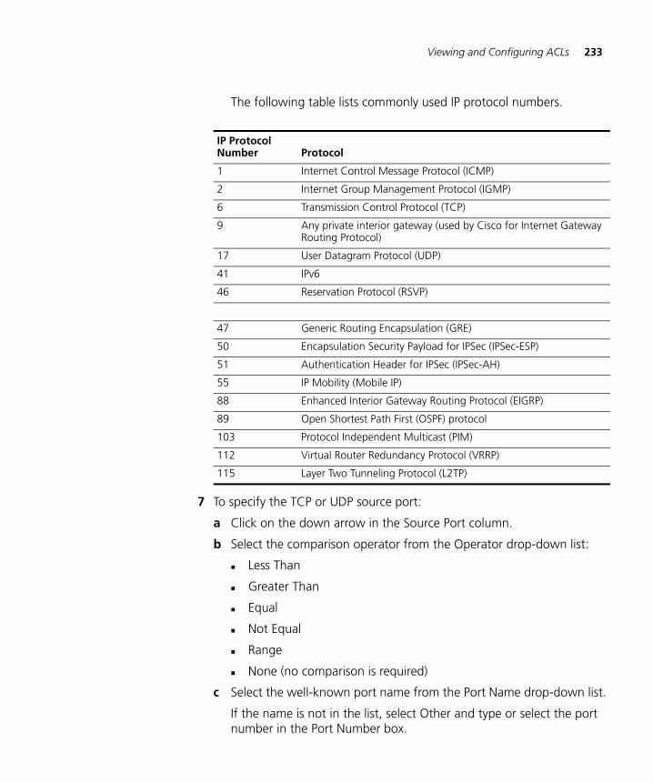
Viewing and Configuring ACLs 233
The following table lists commonly used IP protocol numbers.
7 To specify the TCP or UDP source port:
a Click on the down arrow in the Source Port column.
b Select the comparison operator from the Operator drop-down list:
Less Than
Greater Than
Equal
Not Equal
Range
None (no comparison is required)
c Select the well-known port name from the Port Name drop-down list.
If the name is not in the list, select Other and type or select the port number in the Port Number box.
IP Protocol Number Protocol
1 Internet Control Message Protocol (ICMP)
2 Internet Group Management Protocol (IGMP)
6 Transmission Control Protocol (TCP)
9 Any private interior gateway (used by Cisco for Internet Gateway Routing Protocol)
17 User Datagram Protocol (UDP)
41 IPv6
46 Reservation Protocol (RSVP)
47 Generic Routing Encapsulation (GRE)
50 Encapsulation Security Payload for IPSec (IPSec-ESP)
51 Authentication Header for IPSec (IPSec-AH)
55 IP Mobility (Mobile IP)
88 Enhanced Interior Gateway Routing Protocol (EIGRP)
89 Open Shortest Path First (OSPF) protocol
103 Protocol Independent Multicast (PIM)
112 Virtual Router Redundancy Protocol (VRRP)
115 Layer Two Tunneling Protocol (L2TP)
234 CHAPTER 6: CONFIGURING WX SYSTEM PARAMETERS
d If you selected Range as the comparison operator, type or select the ending port number of the range in the Range End box. The number must be higher than the port number in the Port Number box.
e Click OK.
8 Specify the TCP or UDP destination source port. The options are the same as those for the source port.
9 To match based on DSCP value or IP TOS and IP precedence values:
a Click on the down arrow in the DSCP column.
b Select Type Of Service or Diff-Serv Code Point.
c If you selected Type Of Service, select the IP precedence value from the Precedence drop-down list.
Any (-1)—All packets are subject to the ACL regardless of whether precedence is set.
Routine (0)—Packets with routine precedence are filtered.
Priority (1)—Packets with priority precedence are filtered.
Immediate (2)—Packets with immediate precedence are filtered.
Flash (3)—Packets with flash precedence are filtered.
Flash Override (4)—Packets with flash override precedence are filtered.
CRITIC/ECP (5)—Packets with critical precedence are filtered.
Internetwork Control (6)—Packets with internetwork control precedence are filtered.
Network Control (7)—Packets with network control precedence are filtered.
Select the ToS value in the TOS box.
-1 (any)—All packets are subject to the ACE regardless of whether TOS is set.
0 (normal)—Packets with normal TOS defined are filtered.
1 (minimum monetary cost)—Packets with minimum monetary cost TOS defined are filtered.
2 (maximum reliability)—Packets with maximum reliability TOS defined are filtered.
4 (maximum throughput)—Packets with maximum throughput TOS defined are filtered.
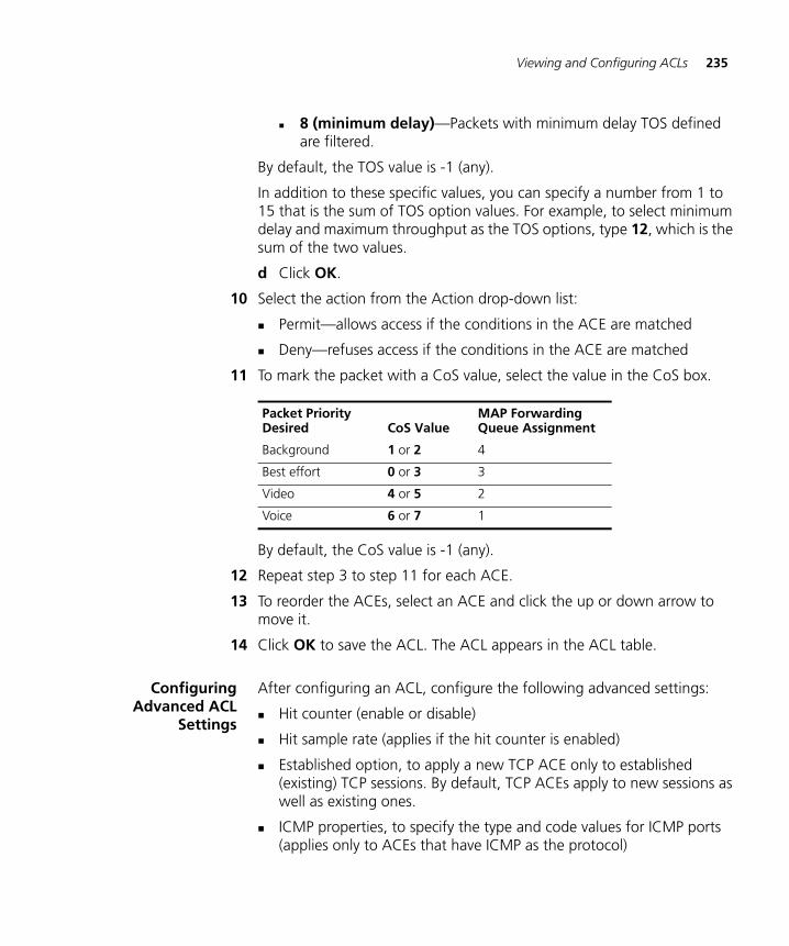
Viewing and Configuring ACLs 235
8 (minimum delay)—Packets with minimum delay TOS defined are filtered.
By default, the TOS value is -1 (any).
In addition to these specific values, you can specify a number from 1 to 15 that is the sum of TOS option values. For example, to select minimum delay and maximum throughput as the TOS options, type 12, which is the sum of the two values.
d Click OK.
10 Select the action from the Action drop-down list:
Permit—allows access if the conditions in the ACE are matched
Deny—refuses access if the conditions in the ACE are matched
11 To mark the packet with a CoS value, select the value in the CoS box.
By default, the CoS value is -1 (any).
12 Repeat step 3 to step 11 for each ACE.
13 To reorder the ACEs, select an ACE and click the up or down arrow to move it.
14 Click OK to save the ACL. The ACL appears in the ACL table.
ConfiguringAdvanced ACL
Settings
After configuring an ACL, configure the following advanced settings:
Hit counter (enable or disable)
Hit sample rate (applies if the hit counter is enabled)
Established option, to apply a new TCP ACE only to established (existing) TCP sessions. By default, TCP ACEs apply to new sessions as well as existing ones.
ICMP properties, to specify the type and code values for ICMP ports (applies only to ACEs that have ICMP as the protocol)
Packet Priority Desired CoS Value
MAP Forwarding Queue Assignment
Background 1 or 2 4
Best effort 0 or 3 3
Video 4 or 5 2
Voice 6 or 7 1
236 CHAPTER 6: CONFIGURING WX SYSTEM PARAMETERS
Capture option, to redirect matching packets to the CPU (applies to ACEs used for Web Portal access)
To change the hit sample rate
The hit sample rate specifies the time interval, in seconds, at which the packet counter is sampled for each security ACE on which the hit counter is enabled.
By default, the hit sample rate is 0, even when the hit counter is enabled. To use the hit counter, you must enable it and set the hit sample rate. The hit sample rate applies globally to all ACEs on which the hit counter is enabled.
1 In the Task List panel, select Edit ACL hit sample rate.
2 Select or type the number of seconds between updates in the Hit Sample Rate box.
3 Click OK.
To enable the hit counter for an ACE
You can enable the hit counter on an individual ACE basis.
1 Select the ACE in the ACL table.
2 In the Task List panel, select Enable Hits for this rule.
You also must set the hit sample rate to a value greater than 0, which is the default. (See “To change the hit sample rate”.)
To enable the established option for TCP ACEs
By default, a new TCP ACE applies to new sessions as well as established (existing) sessions. To apply the ACE only to established sessions, enable the established option.
1 Select the TCP ACE in the ACL table.
2 In the Task List panel, select Enable Established Connections.
To specify the type and code for ICMP ACEs
1 Select the ICMP ACE in the ACL table.
2 In the Task List panel, select ICMP Properties.
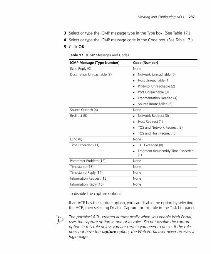
Viewing and Configuring ACLs 237
3 Select or type the ICMP message type in the Type box. (See Table 17.)
4 Select or type the ICMP message code in the Code box. (See Table 17.)
5 Click OK.
To disable the capture option:
If an ACE has the capture option, you can disable the option by selecting the ACE, then selecting Disable Capture for this rule in the Task List panel.
The portalacl ACL, created automatically when you enable Web Portal, uses the capture option in one of its rules. Do not disable the capture option in this rule unless you are certain you need to do so. If the rule does not have the capture option, the Web Portal user never receives a login page.
Table 17 ICMP Messages and Codes
ICMP Message (Type Number) Code (Number)
Echo Reply (0) None
Destination Unreachable (3) Network Unreachable (0)
Host Unreachable (1)
Protocol Unreachable (2)
Port Unreachable (3)
Fragmentation Needed (4)
Source Route Failed (5)
Source Quench (4) None
Redirect (5) Network Redirect (0)
Host Redirect (1)
TOS and Network Redirect (2)
TOS and Host Redirect (3)
Echo (8) None
Time Exceeded (11) TTL Exceeded (0)
Fragment Reassembly Time Exceeded (1)
Parameter Problem (12) None
Timestamp (13) None
Timestamp Reply (14) None
Information Request (15) None
Information Reply (16) None
238 CHAPTER 6: CONFIGURING WX SYSTEM PARAMETERS
Adding a New ACE toa Configured ACL
To add a new ACE to a configured ACL:
1 Access the ACL table:
a Select the Configuration tool bar option.
b In the Organizer panel, click the plus sign next to the WX switch.
c Click the plus sign next to System.
d Select ACLs.
2 Select any ACE in the ACL to which you want to add the new ACE.
3 In the Task List panel, select Add Rules.
4 Go to step 3.
Mapping an ACL An ACL does not take effect until you map it to a user or an interface.
You can map ACLs to ports (or port groups), VLANs, or virtual ports. You cannot map an ACL to a MAP port or a wired authentication port.
You also can map ACLs to user, by configuring the filter.in and filter.out user attributes. User-based ACLs are more specific than ACLs applied to interfaces and are therefore processed first. (See “Authorization Attributes” on page 305.)
1 Access the ACL table:
a Select the Configuration tool bar option.
b In the Organizer panel, click the plus sign next to the WX switch.
c Click the plus sign next to System.
d Select ACLs.
2 Select any ACE in the ACL you want to map.
3 In the Task List panel, select ACL Mappings.
4 Select the mapping type:
To map to a physical port, select port and go to step 5.
To map to a virtual port, select vport and go to step 6.
To map to a VLAN, select vlan and go to step 7.
To map to a Distributed MAP, select dap and go to step 8.
Viewing and Configuring ACLs 239
5 To map an ACL to a port:
a In the Port list, select the port or port group to which you want to map the ACL.
You cannot map an ACL to a MAP port or a wired authentication port.
b In the Direction list, select In to filter incoming packets or Out to filter outgoing packets.
c Click Finish.
6 To map an ACL to a virtual port:
a In the Tag Value box, specify the 802.1Q tag value that identifies a virtual port in a VLAN.
The tag value can be a number from 1 to 4093. The default value is 1.
Make sure that you do not specify duplicate mappings that specify the same port and tag value.
b In the port list, select the port to which you want to map the ACL.
You cannot map an ACL to a MAP port or a wired authentication port.
c In the Direction list, select In to filter incoming packets or Out to filter outgoing packets.
7 To map an ACL to a VLAN:
a In the Type list, select ID to identify the VLAN by number or Name to identify it by name.
If you selected Name, select or type the VLAN name from the Name drop-down list.
If you selected ID, select or type the VLAN number in the ID box.
b In the Direction list, select In to filter incoming packets or Out to filter outgoing packets.
8 To map an ACL to a Distributed MAP:
a In the DAP ID list, select the Distributed MAP from the list.
b In the Direction list, select In to filter incoming packets or Out to filter outgoing packets.
9 Click Finish.
The mapping appears in the ACL Mappings table.
240 CHAPTER 6: CONFIGURING WX SYSTEM PARAMETERS
Deleting an ACL To delete an ACL:
1 Access the ACL table:
a Select the Configuration tool bar option.
b In the Organizer panel, click the plus sign next to the WX switch.
c Click the plus sign next to System.
d Select ACLs.
2 Select any ACE in the ACL you want to delete.
3 In the Task List panel, select Delete ACL.
Deleting anIndividual ACE from
an ACL
To delete an individual ACE from an ACL:
1 Access the ACL table:
a Select the Configuration tool bar option.
b In the Organizer panel, click the plus sign next to the WX switch.
c Click the plus sign next to System.
d Select ACLs.
2 Select any ACE in the ACL.
3 In the Task List panel, select ACL Rules.
4 Select the ACE and click Delete.
5 Click OK.
You cannot delete the ACE at the bottom of the list. This ACE is added to the ACL automatically and cannot be deleted. The ACE at the bottom denies all traffic that does not match other ACEs in the ACL.
Viewing and Changing CoS Mappings 241
Viewing and Changing CoS Mappings
MSS supports Layer 2 and Layer 3 classification and marking of traffic, to help provide end-to-end QoS throughout the network. QoS support includes support of Wi-Fi Multimedia (WMM), which provides wireless QoS for time-sensitive applications such as voice and video.
QoS support is automatically enabled. WX switches and MAPs each provide QoS:
WX switches classify and mark traffic based on 802.1p tag value (for tagged traffic) or Differentiated Services Code Point (DSCP) value.
MAPs classify ingress traffic from wireless clients based on the service type value in the 802.11 header, and mark the DSCP value in the IP tunnel on which the MAP forwards the user traffic to the WX.
MAPs place traffic from a WX to a wireless client in a forwarding queue based on the DSCP value in the tunnel carrying the traffic, then forward the traffic based on the priority.
MSS performs classification on ingress to determine the CoS value. This CoS value is used to mark the packet at the egress interface.
The classification and marking performed by the switch depend on whether the ingress interface has an 802.1p or DSCP value other than 0, and whether the egress interface is tagged or is an IP tunnel.
The mappings between DSCP and CoS values are configurable.
(For more information about how MSS QoS works, see the “Configuring Quality of Service” chapter in the Wireless LAN Switch and Controller Configuration Guide.)
Viewing CoSMappings
To view CoS mappings:
1 Select the Configuration tool bar option.
2 In the Organizer panel, click the plus sign next to the WX switch.
3 Click the plus sign next to System.
4 Select QoS.
The QoS mappings appear in the Content panel. The DSCP to CoS table lists the internal CoS values to which MSS maps DSCP values during classification of ingress traffic. The CoS to DSCP table lists the DSCP values to which MSS maps internal CoS values during marking of egress traffic.
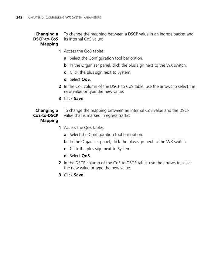
242 CHAPTER 6: CONFIGURING WX SYSTEM PARAMETERS
Changing aDSCP-to-CoS
Mapping
To change the mapping between a DSCP value in an ingress packet and its internal CoS value:
1 Access the QoS tables:
a Select the Configuration tool bar option.
b In the Organizer panel, click the plus sign next to the WX switch.
c Click the plus sign next to System.
d Select QoS.
2 In the CoS column of the DSCP to CoS table, use the arrows to select the new value or type the new value.
3 Click Save.
Changing aCoS-to-DSCP
Mapping
To change the mapping between an internal CoS value and the DSCP value that is marked in egress traffic:
1 Access the QoS tables:
a Select the Configuration tool bar option.
b In the Organizer panel, click the plus sign next to the WX switch.
c Click the plus sign next to System.
d Select QoS.
2 In the DSCP column of the CoS to DSCP table, use the arrows to select the new value or type the new value.
3 Click Save.
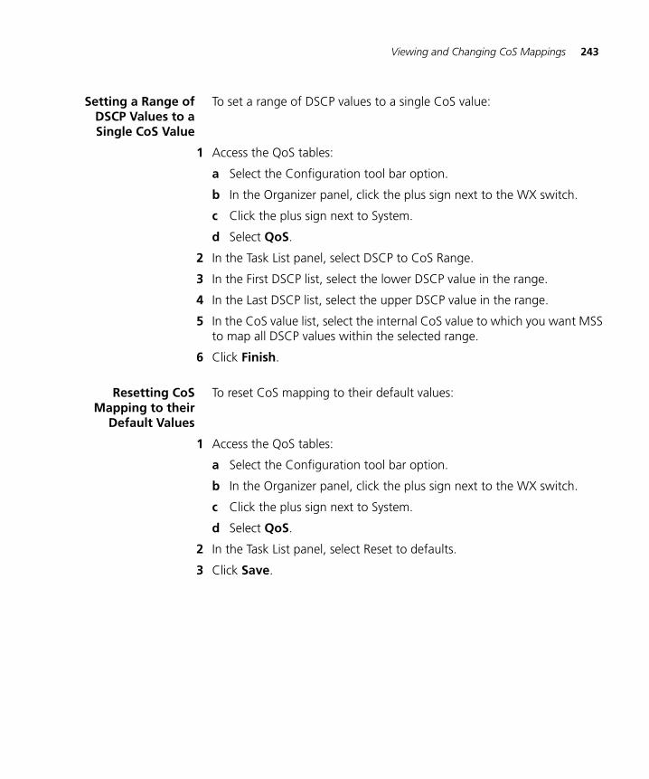
Viewing and Changing CoS Mappings 243
Setting a Range ofDSCP Values to aSingle CoS Value
To set a range of DSCP values to a single CoS value:
1 Access the QoS tables:
a Select the Configuration tool bar option.
b In the Organizer panel, click the plus sign next to the WX switch.
c Click the plus sign next to System.
d Select QoS.
2 In the Task List panel, select DSCP to CoS Range.
3 In the First DSCP list, select the lower DSCP value in the range.
4 In the Last DSCP list, select the upper DSCP value in the range.
5 In the CoS value list, select the internal CoS value to which you want MSS to map all DSCP values within the selected range.
6 Click Finish.
Resetting CoSMapping to their
Default Values
To reset CoS mapping to their default values:
1 Access the QoS tables:
a Select the Configuration tool bar option.
b In the Organizer panel, click the plus sign next to the WX switch.
c Click the plus sign next to System.
d Select QoS.
2 In the Task List panel, select Reset to defaults.
3 Click Save.

244 CHAPTER 6: CONFIGURING WX SYSTEM PARAMETERS
7 CONFIGURING WIRELESS PARAMETERS
This chapter describes how to view and configure the following wireless parameters for WX switches:
Service Set Identifiers (SSIDs), which are managed by service profiles
Radio profiles, which assign IEEE 802.11 settings and a service profile to radios
Auto-DAP profile
MAPs
MAP radios
RF detection
Viewing and Configuring Wireless Services
3WXM provides wizards to configure the following types of wireless services:
802.1X Service Profile—Provides wireless access to 802.1X clients.
Voice Service Profile—Provides wireless access to Voice over IP (VoIP) devices.
Web-Portal Service Profile—Provides wireless access to clients who log in using a web page.
Open Access Service Profile—Provides wireless access to clients without requiring them to log in.
Custom Service Profile—Provides wireless access based on the combination of options you choose. (Use this option only if none of the other options applies to the type of service you want to offer.)
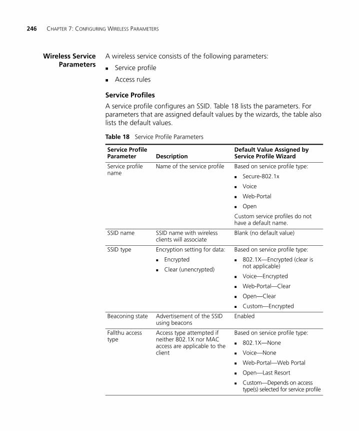
246 CHAPTER 7: CONFIGURING WIRELESS PARAMETERS
Wireless ServiceParameters
A wireless service consists of the following parameters:
Service profile
Access rules
Service Profiles
A service profile configures an SSID. Table 18 lists the parameters. For parameters that are assigned default values by the wizards, the table also lists the default values.
Table 18 Service Profile Parameters
Service Profile Parameter Description
Default Value Assigned by Service Profile Wizard
Service profile name
Name of the service profile Based on service profile type:
Secure-802.1x
Voice
Web-Portal
Open
Custom service profiles do not have a default name.
SSID name SSID name with wireless clients will associate
Blank (no default value)
SSID type Encryption setting for data:
Encrypted
Clear (unencrypted)
Based on service profile type:
802.1X—Encrypted (clear is not applicable)
Voice—Encrypted
Web-Portal—Clear
Open—Clear
Custom—Encrypted
Beaconing state Advertisement of the SSID using beacons
Enabled
Fallthu access type
Access type attempted if neither 802.1X nor MAC access are applicable to the client
Based on service profile type:
802.1X—None
Voice—None
Web-Portal—Web Portal
Open—Last Resort
Custom—Depends on access type(s) selected for service profile
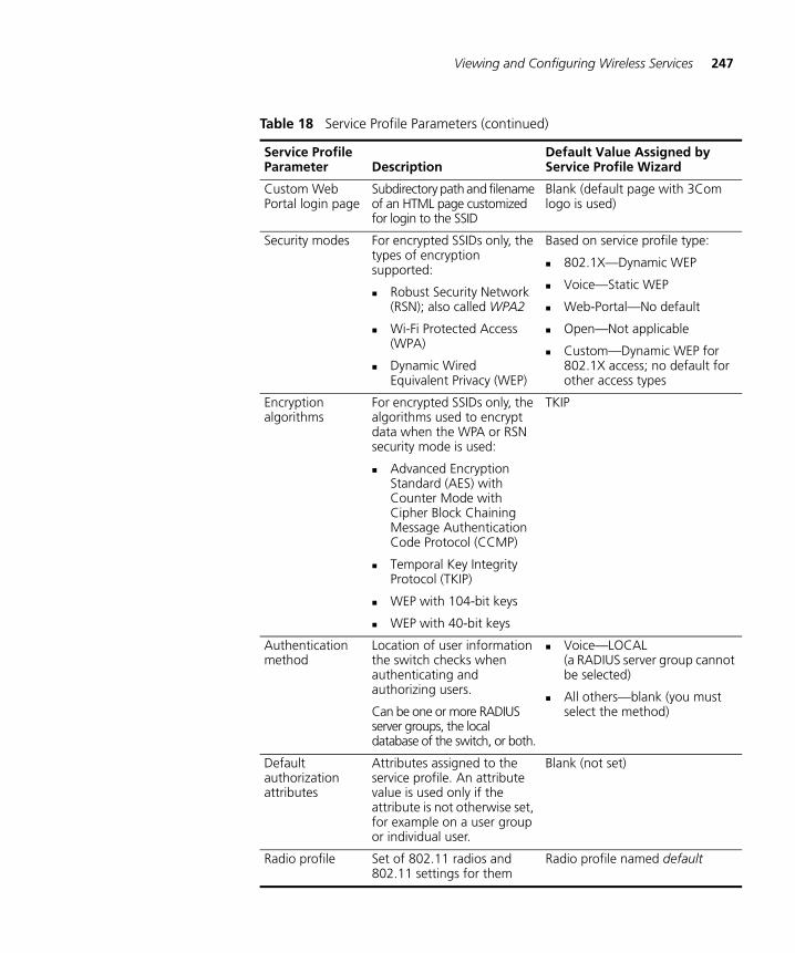
Viewing and Configuring Wireless Services 247
Custom Web Portal login page
Subdirectory path and filename of an HTML page customized for login to the SSID
Blank (default page with 3Com logo is used)
Security modes For encrypted SSIDs only, the types of encryption supported:
Robust Security Network (RSN); also called WPA2
Wi-Fi Protected Access (WPA)
Dynamic Wired Equivalent Privacy (WEP)
Based on service profile type:
802.1X—Dynamic WEP
Voice—Static WEP
Web-Portal—No default
Open—Not applicable
Custom—Dynamic WEP for 802.1X access; no default for other access types
Encryption algorithms
For encrypted SSIDs only, the algorithms used to encrypt data when the WPA or RSN security mode is used:
Advanced Encryption Standard (AES) with Counter Mode with Cipher Block Chaining Message Authentication Code Protocol (CCMP)
Temporal Key Integrity Protocol (TKIP)
WEP with 104-bit keys
WEP with 40-bit keys
TKIP
Authentication method
Location of user information the switch checks when authenticating and authorizing users.
Can be one or more RADIUS server groups, the local database of the switch, or both.
Voice—LOCAL (a RADIUS server group cannot be selected)
All others—blank (you must select the method)
Default authorization attributes
Attributes assigned to the service profile. An attribute value is used only if the attribute is not otherwise set, for example on a user group or individual user.
Blank (not set)
Radio profile Set of 802.11 radios and 802.11 settings for them
Radio profile named default
Table 18 Service Profile Parameters (continued)
Service Profile Parameter Description
Default Value Assigned by Service Profile Wizard
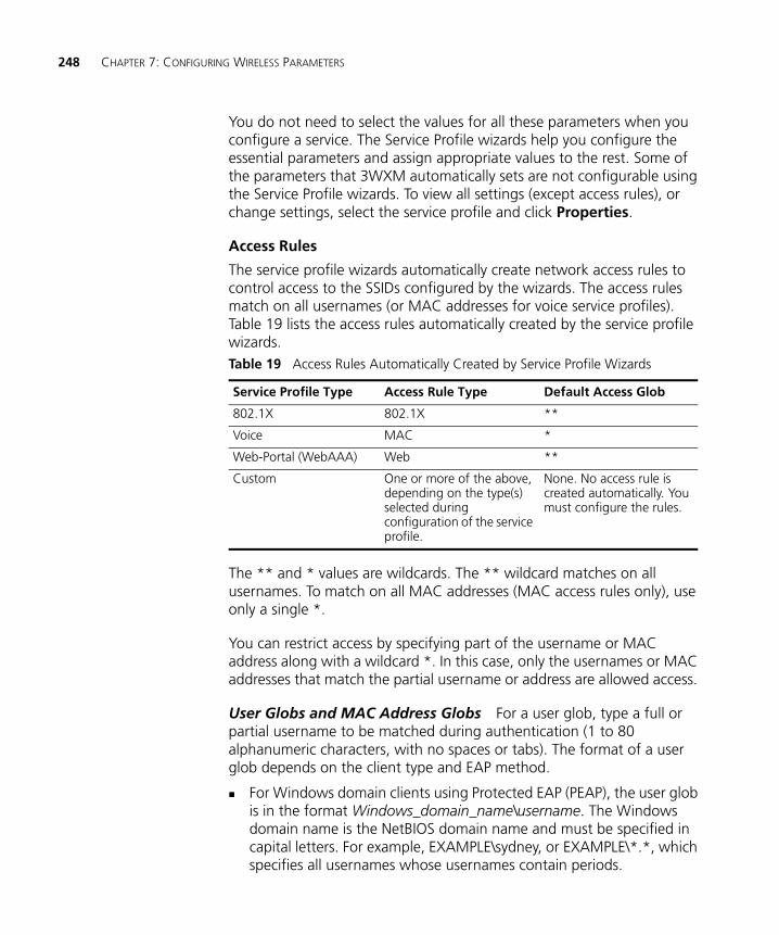
248 CHAPTER 7: CONFIGURING WIRELESS PARAMETERS
You do not need to select the values for all these parameters when you configure a service. The Service Profile wizards help you configure the essential parameters and assign appropriate values to the rest. Some of the parameters that 3WXM automatically sets are not configurable using the Service Profile wizards. To view all settings (except access rules), or change settings, select the service profile and click Properties.
Access Rules
The service profile wizards automatically create network access rules to control access to the SSIDs configured by the wizards. The access rules match on all usernames (or MAC addresses for voice service profiles). Table 19 lists the access rules automatically created by the service profile wizards.
The ** and * values are wildcards. The ** wildcard matches on all usernames. To match on all MAC addresses (MAC access rules only), use only a single *.
You can restrict access by specifying part of the username or MAC address along with a wildcard *. In this case, only the usernames or MAC addresses that match the partial username or address are allowed access.
User Globs and MAC Address Globs For a user glob, type a full or partial username to be matched during authentication (1 to 80 alphanumeric characters, with no spaces or tabs). The format of a user glob depends on the client type and EAP method.
For Windows domain clients using Protected EAP (PEAP), the user glob is in the format Windows_domain_name\username. The Windows domain name is the NetBIOS domain name and must be specified in capital letters. For example, EXAMPLE\sydney, or EXAMPLE\*.*, which specifies all usernames whose usernames contain periods.
Table 19 Access Rules Automatically Created by Service Profile Wizards
Service Profile Type Access Rule Type Default Access Glob
802.1X 802.1X **
Voice MAC *
Web-Portal (WebAAA) Web **
Custom One or more of the above, depending on the type(s) selected during configuration of the service profile.
None. No access rule is created automatically. You must configure the rules.
Viewing and Configuring Wireless Services 249
For EAP with Transport Layer Security (EAP-TLS) clients, the format is username@domain_name. For example, [email protected] specifies the user sydney in the domain name example.com. The *@marketing.example.com glob specifies all users in the marketing department at example.com. The user glob [email protected] specifies the user sydney in the engineering department at example.com.
For a MAC address glob, type a full or partial username to be matched during authentication. MAC addresses must be specified with colons as the delimiters (for example, 00:11:22:33:44:55). You can use wildcards by specifying an asterisk (*) in MAC addresses. The following lists examples of using wildcards in MAC addresses:
* (all MAC addresses)
00:*
00:01:*
00:01:02*
00:01:02:03:*
00:01:02:03:04:*
00:01:02:03:04:0*
To view the access rules of a service profile, see “Viewing SSID Encryption Settings and Access Rules” on page 268. To edit or create access rules for a service profile, see “Modifying SSID Encryption Settings and Access Rules” on page 269.
EAP Type (802.1X Only) 802.1X access rules include information about the Extensible Authentication Protocol (EAP) type to use for AAA communication between the client and the AAA server. The EAP type can be one of the following:
EAP-MD5 Offload—Extensible Authentication Protocol (EAP) with message-digest algorithm 5. Select this protocol for wired authentication clients.
Uses challenge-response to compare hashes.
Provides no encryption or integrity checking for the connection.
The EAP-MD5 option does not work with Microsoft wired authentication clients.
250 CHAPTER 7: CONFIGURING WIRELESS PARAMETERS
PEAP Offload—Protected EAP with Microsoft Challenge Handshake Authentication Protocol Version 2 (MS-CHAP-V2). Select this protocol for wireless clients.
Uses TLS for encryption and data integrity checking.
Provides MS-CHAP-V2 mutual authentication.
Only the server side of the connection needs a certificate.
Local EAP-TLS—EAP with TLS.
Provides mutual authentication, integrity-protected negotiation, and key exchange.
Requires X.509 public key certificates on both sides of the connection.
Provides encryption and integrity checking for the connection.
Cannot be used with RADIUS server authentication (requires user information to be in the local database of the switch)
External RADIUS Server—No protocol is used by the WX. The switch sends the authentication traffic to a RADIUS server for EAP processing.
If you select PEAP, the EAP Sub-Protocol is MS-CHAPV2. For other protocols, the EAP Sub-Protocol is None.
Other access types do not use EAP.
AAA Methods (RADIUS Server Groups and the Local User Database) In addition to user globs or MAC address globs, access rules specify AAA methods, which can be one or both of the following:
RADIUS server group—Named set of RADIUS servers.
LOCAL—Local user database of a switch.
You can select both a server group and LOCAL. The switch tries the methods in the order they appear in the list, starting with the one at the top.
If you specify a RADIUS server group as the first method and a user is denied access by the RADIUS server, no authentication and authorization are attempted with the other methods specified in the list.
If you specify LOCAL as the first method and a user is not in the local user database on the WX, authentication and authorization are attempted with a RADIUS server group if one is defined in the method list.
Viewing and Configuring Wireless Services 251
The methods you select for authentication are also used for authorization. You also can configure accounting for Start-Stop or Stop-Only messages. The authentication method(s) for accounting can be but are not required to be the same as the method(s) for authentication and authorization.
If you plan to specify a RADIUS server group, configure the group first, before using the wizard. To be available for selection in the wizard, the RADIUS server group must already be configured before you open the wizard. (See “Viewing and Configuring RADIUS Settings” on page 311.)
Viewing WirelessServices
To view wireless services:
1 Select the Configuration tool bar option.
2 In the Organizer panel, click the plus sign next to the WX switch.
3 Click the plus sign next to Wireless.
4 Select Wireless Services.
The service profiles appear in the Content panel. Each row in the table shows settings for an individual service profile.
To display all settings for a service profile, select the service profile and click Properties.
Configuring an802.1X Wireless
Service
The 802.1X Service Profile wizard requires you to select one or more RADIUS server groups and does not allow you to complete the configuration without selecting one. To be available for selection in the wizard, a RADIUS server group must already be configured before you open the wizard. (See “Viewing and Configuring RADIUS Settings” on page 311.)
1 Access the 802.1X Service Profile wizard:
a In the Organizer panel, click on the plus sign next to the WX switch on which you want to configure the service profile.
b Click on the plus sign next to Wireless.
c Select Wireless Services.
d In the Task List panel, select 802.1X Service Profile.
2 Read the description of the wizard on the first page, then click Next.
3 Edit the service name in the Name box.
252 CHAPTER 7: CONFIGURING WIRELESS PARAMETERS
Editing the name is optional if this is the first service of this type you are configuring on the switch.
4 Type the SSID name in the SSID box.
5 Click Next.
6 Select the security modes you want the SSID to support. You can select one or more of the following:
RSN (WPA2)
WPA
Dynamic WEP
7 Click Next.
8 If you selected RSN or WPA in step 6, select the encryption algorithms to use. Otherwise, go to step 11.
AES (CCMP)—Usually used with RSN (WPA2)
TKIP—Usually used with WPA
WEP-104—Used with dynamic WEP
WEP-40—Used with dynamic WEP
9 Click Next.
10 Select the EAP type:
EAP-MD5 Offload
PEAP Offload
Local EAP-TLS
External RADIUS Server
If you select PEAP, the EAP Sub-Protocol is MS-CHAPV2. For other protocols, the EAP Sub-Protocol is None.
(For information, see “EAP Type (802.1X Only)” on page 249.)
11 Specify the authentication method (RADIUS server group or local database).
(For information, see “AAA Methods (RADIUS Server Groups and the Local User Database)” on page 250.)
12 Click Next.
13 To assign a default VLAN to the SSID, select the VLAN from the VLAN Name drop-down list.
Viewing and Configuring Wireless Services 253
The VLAN and other authorization attributes can be assigned to users in the local database, on remote servers, or in the service profile of the SSID the user logs into. The VLAN you select here is used only if a VLAN attribute is not configured for the user on the RADIUS server or in the local database of a switch.
14 Select or create the radio profile to map to this service profile.
By default, the default radio profile is selected.
To map the service profile to the default radio profile, leave default selected and go to step 15.
To map the service profile to a different radio profile, select the radio profile and go to step 15.
To create a new radio profile:
a Select Create new Radio Profile and click Next.
b Type the radio profile name in the Name box and click Next.
c Select the radios you want to manage with the radio profile and click Move to move them to the Current Members list.
If you have not planned RF coverage or configured any MAPs in the network plan yet, no radios are listed. You can add the radios later. (Select the radio profile, click Properties, then select Radio Selection. See “Configuring Advanced Radio Profile Settings” on page 274.)
d Go to step 15.
15 Click Finish.
The service profile appears in the service profile table.
Configuring a Voiceover Wireless Service
If the VoIP devices use Wi-Fi Multimedia, you do not need to configure a service profile. WMM is supported automatically. A voice service profile is required only for non-WMM devices.
1 Access the Voice Service Profile wizard:
a In the Organizer panel, click on the plus sign next to the WX switch on which you want to configure the service profile.
b Click on the plus sign next to Wireless.
c Select Wireless Services.
d In the Task List panel, select Voice Service Profile.
2 Read the description of the wizard on the first page, then click Next.
254 CHAPTER 7: CONFIGURING WIRELESS PARAMETERS
3 Edit the service name in the Name box.
Editing the name is optional if this is the first service of this type you are configuring on the switch.
4 Type the SSID name in the SSID box.
5 Select the SSID type from the SSID Type box:
Encrypted—Traffic on the SSID is encrypted.
Clear—Traffic on the SSID is unencrypted.
6 Select the VoIP vendor from the Vendor drop-down list:
SpectraLink—Non-WMM SVP devices
Vocera—Non-WMM Vocera devices
Avaya—Non-WMM Avaya devices
Other—Non-WMM devices that are not SVP or Avaya phones.
7 Click Next.
The next step depends on the encryption type you selected in step 5:
If you selected Encrypted, go to step 8.
If you selected Clear, go to step 18.
8 Select the access type:
802.1X Access—Device is allowed onto the SSID only after successful authentication using 802.1X.
MAC Access—Device is allowed onto the SSID only if its MAC address matches an entry on a RADIUS server or the local database of a switch.
Open Access—All devices are allowed onto the SSID.
9 Click Next.
10 Select the security modes you want the SSID to support. You can select one or more of the following:
RSN (WPA2)
WPA
Static WEP
11 Click Next.
12 If you selected RSN or WPA in step 10, select the encryption algorithms to use. Otherwise, go to step 16.
Viewing and Configuring Wireless Services 255
AES (CCMP)—Usually used with RSN (WPA2)
TKIP—Usually used with WPA
WEP-104—Used with dynamic WEP
WEP-40—Used with dynamic WEP
13 Click Next.
14 If you selected RSN or WPA in step 10, you can select whether to use dynamically generated keys, or static keys based on a passphrase.
To use dynamically generated keys, leave the Pre-shared Key box blank and go to step 15.
To use static keys, type a string from 8 to 63 characters long in the Pre-shared Key box and click Generate.
15 Click Next.
16 If you selected Static WEP in step 12, specify WEP keys. Otherwise, go to step 17.
For each key (up to four), type the key value in the corresponding key box.
By default, data in unicast and multicast packets are encrypted using WEP key 1. To use another key for either type of packet, select the key number in the WEP Unicast Key Index or WEP Multicast Key Index box.
17 Click Next.
18 Select or type the name of the VLAN into which you want the switch to place voice clients.
19 Click Next.
This step and the following step do not apply if the vendor selected in step 6 is Vocera.
If applicable, the ACEs (ACL rules) that 3WXM will configure for the voice service are listed. For non-WMM clients, ACEs are required in order to provide priority treatment of voice traffic. The ACEs differ depending on the vendor you selected in step 6. The wizard describes the ACEs.
If you need to modify the ACEs, go to step 20. Otherwise, go to step 21.
20 To add an ACE, click Add Rule. 3WXM adds an ACE to the end of the list. The ACE matches on all source and destination IP addresses and denies them.
To modify an ACE, select the part of the ACE you want to modify, and edit or select the new value. (For information about ACE settings, see “Viewing and Configuring ACLs” on page 230.)
256 CHAPTER 7: CONFIGURING WIRELESS PARAMETERS
21 If you selected MAC Access in step 8, select or create the MAC address globs you want to allow to access the voice VLAN. Otherwise, go to step 23.
To create a new rule:
a Click Create.
b Specify the MAC address glob in the Matching MAC Glob box. To match on all MAC addresses, leave the wildcard (*) in the box. (For syntax information, see “Access Rules” on page 248.)
To use an existing rule, leave the rule in the list.
22 Select or create the radio profile to map to this service profile.
By default, the default radio profile is selected.
To map the service profile to the default radio profile, leave default selected and go to step 23.
To map the service profile to a different radio profile, select the radio profile and go to step 23.
To create a new radio profile:
a Select Create new Radio Profile and click Next.
b Type the radio profile name in the Name box and click Next.
c Select the radios you want to manage with the radio profile and click Move to move them to the Current Members list.
If you have not planned RF coverage or configured any MAPs in the network plan yet, no radios are listed. You can add the radios later. (Select the radio profile, click Properties, then select Radio Selection. See “Configuring Advanced Radio Profile Settings” on page 274.)
d Go to step 23.
23 Click Finish.
The service profile appears in the service profile table.
Configuring aWeb-Portal
(WebAAA) Service
To configure a Web-Portal (WebAAA) service:
1 Access the Web-Portal Service Profile wizard:
a In the Organizer panel, click on the plus sign next to the WX switch on which you want to configure the service profile.
b Click on the plus sign next to Wireless.
Viewing and Configuring Wireless Services 257
c Select Wireless Services.
d In the Task List panel, select Web-Portal Service Profile.
2 Read the description of the wizard on the first page, then click Next.
3 Edit the service name in the Name box.
Editing the name is optional if this is the first service of this type you are configuring on the switch.
4 Type the SSID name in the SSID box.
5 Select the SSID type:
Encrypted—Traffic on the SSID is encrypted.
Clear—Traffic on the SSID is unencrypted.
6 Click Next.
If you selected Encrypted in step 5, configure the encryption settings. Go to step 7.
If you selected Clear in step 5, go to step 15.
7 Select the security modes you want the SSID to support. You can select one or more of the following:
RSN (WPA2)
WPA
Static WEP
8 Click Next.
9 If you selected RSN or WPA in step 7, you can select whether to use dynamically generated keys, or static keys based on a passphrase.
To use dynamically generated keys, leave the Pre-shared Key box blank and go to step 10.
To use static keys, type a string from 8 to 63 characters long in the Pre-shared Key box and click Generate.
10 Click Next.
11 Select the encryption algorithms to use:
AES (CCMP)—Usually used with RSN (WPA2)
TKIP—Usually used with WPA
WEP-104—Used with dynamic WEP
WEP-40—Used with dynamic WEP
258 CHAPTER 7: CONFIGURING WIRELESS PARAMETERS
12 Click Next.
13 If you selected Static WEP in step 7, specify WEP keys. Otherwise, click Next and go to step 15.
For each key (up to four), type the key value in the corresponding key box.
By default, data in unicast and multicast packets are encrypted using WEP key 1. To use another key for either type of packet, select the key number in the WEP Unicast Key Index or WEP Multicast Key Index box.
14 Click Next.
15 Select or type the name of the VLAN to place clients in.
Clients are placed in this VLAN regardless of any other VLAN assignment. For example, if the VLAN-Name attribute assigns the user to another VLAN, the switch nonetheless places the user in the VLAN you specify here.
16 Click Next.
The ACEs (ACL rules) that 3WXM will configure for the Web-Portal service are listed. The ACEs are required to allow DHCP traffic while blocking all other traffic while a user is being authenticated. These ACEs are used only during authentication. After the user is authenticated, the ACEs are not used.
If you need to add ACEs, use the following procedure. Otherwise, go to step 17.
a Click Next.
b To add an ACE, click Add Rule. 3WXM adds an ACE to the end of the list. The ACE matches on all source and destination IP addresses and denies them.
To modify an ACE, select the part of the ACE you want to modify, and edit or select the new value. (For information about ACE settings, see “Viewing and Configuring ACLs” on page 230.)
CAUTION: Do not change the deny rule at the bottom of the ACL. This rule must be present and the capture option must be used with the rule. If the rule does not have the capture option, the Web Portal user never receives a login page.
17 Click Next.
18 Specify the authentication method (RADIUS server group or local database).
Viewing and Configuring Wireless Services 259
(For information, see “AAA Methods (RADIUS Server Groups and the Local User Database)” on page 250.)
If you selected LOCAL as an authentication method, go to step 19. Otherwise, go to step 21.
19 Click Next.
3WXM lists the users in the local database of a switch. For convenience, you can add, modify, or delete users on this page. To add a user, click Create and see “Creating a Named User” on page 301. To modify a user, select the user and click Properties. To delete a user, select the user and click Delete.
(You can add, modify, or delete users at any time, even after this wizard is closed. See “Creating and Managing Users in the Local User Database” on page 299.)
20 Select or create the radio profile to map to this service profile.
By default, the default radio profile is selected.
To map the service profile to the default radio profile, leave default selected and go to step 21.
To map the service profile to a different radio profile, select the radio profile and go to step 21.
To create a new radio profile:
a Select Create new Radio Profile and click Next.
b Type the radio profile name in the Name box and click Next.
c Select the radios you want to manage with the radio profile and click Move to move them to the Current Members list.
If you have not planned RF coverage or configured any MAPs in the network plan yet, no radios are listed. You can add the radios later. (Select the radio profile, click Properties, then select Radio Selection. See “Configuring Advanced Radio Profile Settings” on page 274.)
d Go to step 21.
21 Click Finish.
260 CHAPTER 7: CONFIGURING WIRELESS PARAMETERS
Configuring an OpenAccess Service
To configure an Open Access service:
1 Access the Open Access Service Profile wizard:
a In the Organizer panel, click on the plus sign next to the WX switch on which you want to configure the service profile.
b Click on the plus sign next to Wireless.
c Select Wireless Services.
d In the Task List panel, select Open Access Service Profile.
2 Read the description of the wizard on the first page, then click Next.
3 Edit the service name in the Name box.
Editing the name is optional if this is the first service of this type you are configuring on the switch.
4 Type the SSID name in the SSID box.
5 Select the SSID type from the SSID Type drop-down list:
Encrypted—Traffic on the SSID is encrypted.
Clear—Traffic on the SSID is unencrypted.
6 Click Next.
If you selected Encrypted in step 5, configure the encryption settings. Go to step 7.
If you selected Clear in step 5, go to step 15.
7 Select the security modes you want the SSID to support. You can select one or more of the following:
RSN (WPA2)
WPA
Static WEP
8 Click Next.
9 If you selected RSN or WPA in step 7, you can select whether to use dynamically generated keys, or static keys based on a passphrase.
To use dynamically generated keys, leave the Pre-shared Key box blank and go to step 10.
To use static keys, type a string from 8 to 63 characters long in the Pre-shared Key box and click Generate.
10 Click Next.
Viewing and Configuring Wireless Services 261
11 Select the encryption algorithms to use:
AES (CCMP)—Usually used with RSN (WPA2)
TKIP—Usually used with WPA
WEP-104—Used with dynamic WEP
WEP-40—Used with dynamic WEP
12 Click Next.
13 If you selected Static WEP in step 7, specify WEP keys. Otherwise, go to step 14.
For each key (up to four), type the key value in the corresponding key box.
By default, data in unicast and multicast packets are encrypted using WEP key 1. To use another key for either type of packet, select the key number in the WEP Unicast Key Index or WEP Multicast Key Index box.
14 Click Next.
15 Select the VLAN into which you want the switch to place users of the SSID.
If you want to specify the VLAN later when configuring the access rules, you can leave the VLAN Name box blank.
16 Select or create the radio profile to map to this service profile.
By default, the default radio profile is selected.
To map the service profile to the default radio profile, leave default selected and go to step 17.
To map the service profile to a different radio profile, select the radio profile and go to step 17.
To create a new radio profile:
a Select Create new Radio Profile and click Next.
b Type the radio profile name in the Name box and click Next.
c Select the radios you want to manage with the radio profile and click Move to move them to the Current Members list.
If you have not planned RF coverage or configured any MAPs in the network plan yet, no radios are listed. You can add the radios later. (Select the radio profile, click Properties, then select Radio Selection. See “Configuring Advanced Radio Profile Settings” on page 274.)
d Go to step 17.
17 Click Finish.
262 CHAPTER 7: CONFIGURING WIRELESS PARAMETERS
Configuring a CustomService
If none of the other service types is appropriate, you can use the Custom Service Profile wizard to configure the service. The screens and options that are displayed depend on the access types and other elections you make as you use the wizard. All pages and options occur in at least one of the other service profile wizards. For information, see the procedures for the other wizards.
Modifying ServiceProfile Settings
You can modify the following service profile settings in the Wireless Service Profiles table itself:
SSID name
SSID type (encrypted or clear)
Beacon state (advertisement of the SSID)
Radio profile (maps MAP radios to the service profile)
To view or change other settings, select the service profile in the Wireless Service Profiles table and click Properties. A dialog with the following tabs is displayed:
Service Profile
WPA, RSN
Static WEP
Authorization Attributes
Broadcast Settings
Radio Profile Selection
Voice Configuration
Client Timeout
Rate Configuration
SODA
Service Profile Tab
The following settings on the Service Profiles tab are explained in the sections on the service profile wizards:
Name
SSID
SSID Type
Viewing and Configuring Wireless Services 263
Beacon
Fall Through Access
For descriptions, see Table 18 on page 246.
The Service Profile tab also has the following settings:
Web-Portal ACL—Specifies the name of the ACL MSS uses to filter a Web-Portal user’s traffic during authentication. This option is applicable only to the Web Portal fallthru authentication type.
Web Portal Page—Specifies the name of a custom login page served to clients users when accessing the Web Portal SSID.
Keep Initial VLAN—When enabled, this option prevents a user from being reassigned to a new VLAN after roaming from one WX switch to another. (For more information, see the “Keeping Users on the Same VLAN Even After Roaming” section of the “Configuring AAA for Network Users” chapter in the Wireless LAN Switch and Controller Configuration Guide.)
WPA, RSN Tab
Most of the settings on the WPA, RSN tab are explained in the sections on the service profile wizards.
The TKIP Countermeasures Time specifies how many ms the switch will hold down traffic on the SSID if more than one Message Integrity Check (MIC) error occurs within a one-minute interval. You can specify from 0 to 60000 (one minute). The default is 60000.
Static WEP Tab
All of the settings on the Static WEP tab are explained in the sections on the service profile wizards.
Authorization Attributes Tab
The Authorization Attributes tab lists the default authorization attributes for the SSID. When a user is authorized for the SSID, the switch applies the default attributes to the user unless those attributes are otherwise specified. For example, if a default session-timeout is set for the SSID, and the session-timeout attribute is not defined as part of the individual user or the user’s group, the switch assigns the default session-timeout of the SSID o the user.
264 CHAPTER 7: CONFIGURING WIRELESS PARAMETERS
Where applicable, the service profile wizards allow you to specify the default VLAN of the SSID but do not allow configuration of the other default attributes.
To change the default VLAN, select it from the VLAN-Name box. To set other default attributes, click in the value column and type the values.
(For more information about attributes and how they are selected, see the “Assigning Authorization Attributes” section in the “Configuring AAA for Network Users” chapter of the Wireless LAN Switch and Controller Configuration Guide.)
Broadcast Settings Tab
The Broadcast Settings tab lists the settings for the following broadcast control features. These features help enhance throughput for client data by reducing the amount of bandwidth used by broadcast traffic.
Proxy ARP—WX responds on behalf of wireless clients to ARP requests for their IP addresses.
DHCP Restrict—WX captures and does not forward any traffic except DHCP traffic for a wireless client who is still being authenticated and authorized.
No Broadcast—Sends unicasts to clients for ARP requests and DHCP Offers and Acks instead of forwarding them as multicasts.
3WXM disables all of these broadcast control options by default.
Radio Profile Selection Tab
The Radio Profile Selection tab list the radio profiles mapped to the service profiles. Service profile wizards map the service profiles to the default radio profile by default.
To map another radio profile to the service profile, select the radio profile in the Available Radio Profiles list, then click Add.
To unmap a radio profile from the service profile, select the radio profile in the Current Radio Profiles list, then click Remove.
Voice Configuration Tab
The Voice Configuration tab lists settings used for VoIP service profiles. For some options, the settings selected by 3WXM differ depending on the vendor you select when you create the service profile.
Viewing and Configuring Wireless Services 265
Static CoS—When enabled, marks all traffic on the SSID with the same CoS value (the Static CoS Value). This option is automatically enabled for Vocera voice service profiles but is disabled for all other service profile types.
Static CoS Value—CoS value assigned by the MAP to all traffic on the SSID of the service profile, when static CoS is enabled. This value is used only when static CoS is enabled. The default is 0 if you enable static CoS manually. However, if static CoS is enabled automatically as part of a Vocera service profile, the default is 7 (highest priority).
CAC Mode—Call Admission Control (CAC) policy for allowing new sessions on the radios serving an SSID:
None—CAC is disabled. This is the setting automatically selected for all service profile types except Vocera voice service profiles.
Sessions—CAC is session-based. A MAP radio cannot have more than the specified number of active sessions for the SSID. This is the setting automatically selected for Vocera voice service profiles.
Max Sessions—When the CAC mode is Sessions, it specifies the maximum number of active sessions radios can have for the SSID. The default is 12.
Short Retry Count—Number of times (1 to 15) the MAP transmits an unacknowledged unicast frame that is shorter than the fragment threshold before discarding the frame. The default is 5.
Long Retry Count—Number of times (1 to 15) the MAP transmits an unacknowledged unicast frame that is equal to or longer than the fragment threshold before discarding the frame. The default is 5.
Client Timeout Tab
The Client Timeout tab lists settings for client session timers:
User idle timeout—Number of seconds a client can remain idle before the client’s session is changed to the Disassociated state. A client is considered to be idle until it either sends data or responds to an idle client probe. You can specify from 20 to 86400 seconds. The default is 180 seconds (3 minutes.) To disable the timer, specify 0.
Idle client probing—When enabled, sends a keepalive probe (a null data frame) to each wireless client. The frame is sent as a unicast. The WX expects a reply in the form of an Ack. Idle client probing is enabled by default.
266 CHAPTER 7: CONFIGURING WIRELESS PARAMETERS
Web-portal session timeout—Specifies how many seconds MSS waits after a Web-Portal client enters the Disassociated state before terminating the client’s session. This can be useful if you want to allow a client connecting through Web Portal WebAAA to enter standby or hibernation mode, then be able to resume its session after waking up, without having to log in again. You can specify from 5 seconds up to 2800 seconds (a little over 46 minutes). The default is 5 seconds. The timeout change applies globally for all Web-Portal sessions on the SSID of the service profile. This option applies only to Web-Portal service profiles.
Rate Configuration Tab
The Rate Configuration tab lists the data rates supported and used by MAP radios. For each radio type (802.11a, 802.11b, and 802.11g), the following rates are individually configurable:
Beacon rate—Data rate at which the radio sends beacon (SSID advertisement) frames and probe-response frames. The valid rates depend on the radio type and are the same as the mandatory rates. However, you cannot set the beacon rate to a disabled rate. The default depends on the radio type:
802.11a—6.0
802.11b—2.0
802.11g—2.0
Multicast rate—Data rate at which the radio sends multicast frames. The valid rates depend on the radio type and are the same as the mandatory rates. The default is Automatic, which sets the multicast rate to the highest rate that can reach all clients connected to the radio.
Mandatory rates—Set of data transmission rates that clients are required to support in order to associate with an SSID on a MAP radio. A client must support at least one of the mandatory rates. These rates are advertised in the basic rate set of 802.11 beacons, probe responses, and reassociation response frames sent by MAP radios.
Management frames sent by MAP radios use one of the specified mandatory rates.
The valid rates depend on the radio type:
802.11a—6.0, 9.0, 12.0, 18.0, 24.0, 36.0, 48.0, 54.0
802.11b—1.0, 2.0, 5.5, 11.0
Viewing and Configuring Wireless Services 267
802.11g—1.0, 2.0, 5.5, 6.0, 9.0, 11.0, 12.0, 18.0, 24.0, 36.0, 48.0, 54.0
The default depends on the radio type:
802.11a—6.0, 12.0, and 24.0
802.11b—1.0, and 2.0
802.11g—1.0, 2.0, 5.5, and 11.0
Supported rates—Rates that are not mandatory but that the radio can nonetheless use to send data. By default, all valid rates that are not mandatory are still supported.
Disabled rates—Data transmission rates that MAP radios will not use to transmit data. This setting applies only to data sent by the MAP radios. The radios will still accept frames from clients at disabled data rates. By default, none of the data rates are disabled.
All rate settings apply specifically to data rates used by radios for transmission. Radios can accept frames from a wireless client at any valid rate.
SODA Tab
The SODA tab has settings for the Sygate On-Demand (SODA) feature. SODA is an endpoint security solution that allows enterprises to enforce security policies on client devices without having to install any special software on the client machines. WX switches can be configured to run SODA security checks on users’ machines as a requirement for gaining access to the network.
Sygate on Demand—Enables or disables SODA on the SSID of the service profile. When SODA functionality is enabled for a service profile, a SODA agent is downloaded to clients attempting to connect to a MAP managed by the service profile. The SODA agent performs a series of security-related checks on the client.
Enforce checks—Enables or disables the enforcement of the SODA security checks, so that the client is allowed access to the network immediately after the SODA agent is downloaded, rather than waiting for the security checks to be run.
Remediation ACL—ACL to be applied to a client if it fails the checks performed by the SODA agent.
Failure Page—Name of the web page served to the user’s browser if the user’s computer fails one of the SODA agent checks.
268 CHAPTER 7: CONFIGURING WIRELESS PARAMETERS
Success Page—Name of the web page served to the user’s browser when the user’s computer successfully completes all of the SODA agent checks.
Logout Page—Name of the web page served to the user’s browser when the user logs out of the SODA-protected network.
Agent Directory—Name of the directory in the nonvolatile storage for the WX switch that contains the SODA agent files.
Viewing SSIDEncryption Settings
and Access Rules
The encryption settings and access rules of a service profile are not displayed in the service profile table or in the wizard opened by the Properties button.
To display encryption settings and access rules of an SSID from the Service Profile table
1 Display the Wireless Service Profiles table:
a In the Organizer panel, click on the plus sign next to the WX switch on which the service profile is configured.
b Click on the plus sign next to Wireless.
c Select Wireless Services.
2 Select the service profile in the table.
A set of tasks appears under Setup in the Task List panel.
3 To display encryption settings and access rules, select one of the following in the Task List panel:
802.1X Access
MAC Access
Web Portal Access
Open Access
To display the access rules only, select Access Rules.
To display encryption settings and access rules of an SSID in an Access Rule table
1 In the Organizer panel, click on the plus sign next to the WX switch on which the service profile is configured.
2 Click on the plus sign next to AAA.
Viewing and Configuring Wireless Services 269
3 Select the type of access rule assigned to the service profile:
802.1X Access Rules—for 802.1 service profiles
MAC Access Rules—for Voice service profiles
Web Access Rules—for Web-Portal (WebAAA) service profiles
Last Resort Access Rules—for Open service profiles
For a custom service profile, the option to select depends on the access rule type selected when the service profile was created.
After selecting the access rule type, 3WXM displays a table listing all of the access rules of that type configured on the WX switch.
4 Look in the SSID column for the SSID name configured in the service profile, and select the table row.
5 Click Properties.
A Network Access Properties wizard containing the configuration settings for the access rule appears.
Modifying SSIDEncryption Settings
and Access Rules
You can create access rules for a service profile from within a service profile wizard. You also can create or modify access rules after creating the service profile.
1 Display the Wireless Service Profiles table:
a In the Organizer panel, click on the plus sign next to the WX switch on which the service profile is configured.
1 Click on the plus sign next to Wireless.
1 Select Wireless Services.
2 Select the service profile in the table.
A set of tasks appears under Setup in the Task List panel.
3 To configure encryption settings and access rules, select one of the following in the Task List panel and go to “Modifying Encryption Settings”.
802.1X Access
MAC Access (used for voice)
Web Portal Access
Open Access
270 CHAPTER 7: CONFIGURING WIRELESS PARAMETERS
To configure access rules only, select Access Rules and go to “Modifying Access Rules” on page 271.
Modifying Encryption Settings
1 Select the security modes you want the SSID to support. You can select one or more of the following:
RSN (WPA2)
WPA
Static WEP
2 Click Next.
3 If you selected RSN or WPA, you can select whether to use dynamically generated keys, or static keys based on a passphrase.
To use dynamically generated keys, leave the Pre-shared Key box blank.
To use static keys, type a string from 8 to 63 characters long in the Pre-shared Key box and click Generate.
4 Click Next.
5 Select the encryption algorithms to use:
AES (CCMP)—Usually used with RSN (WPA2)
TKIP—Usually used with WPA
WEP-104—Used with dynamic WEP
WEP-40—Used with dynamic WEP
6 Click Next.
7 If you selected Static WEP, specify WEP keys.
For each key (up to four), type the key value in the corresponding key box.
By default, data in unicast and multicast packets are encrypted using WEP key 1. To use another key for either type of packet, select the key number in the WEP Unicast Key Index or WEP Multicast Key Index box.
8 Click Next.
9 If the access type is Web Portal or Open Access, select the VLAN into which you want the switch to place users of the SSID.
If you want to specify the VLAN later when configuring the access rules, you can leave the VLAN Name box blank.
Viewing and Configuring Wireless Services 271
10 Click Next.
If the access type is Web Portal, the ACEs (ACL rules) that 3WXM will configure for the Web-Portal service are listed. The ACEs are required to allow DHCP traffic while blocking all other traffic while a user is being authenticated. These ACEs are used only during authentication. After the user is authenticated, the ACEs are not used.
If you need to add ACEs, continue with this step. Otherwise, click Next and go to “Modifying Access Rules” on page 271 or click Finish to save the changes and close the wizard.
To add an ACE, click Add Rule. 3WXM adds an ACE to the end of the list. The ACE matches on all source and destination IP addresses and denies them.
To modify an ACE, select the part of the ACE you want to modify, and edit or select the new value. (For information about ACE settings, see “Viewing and Configuring ACLs” on page 230.)
Do not change the deny rule at the bottom of the ACL. This rule must be present and the capture option must be used with the rule. If the rule does not have the capture option, the Web Portal user never receives a login page.
11 To modify access rules, click Next and go to “Modifying Access Rules”. Otherwise, click Finish.
Modifying Access Rules
1 If you have not already done so, access the Access Rules Configuration page for the service profile:
a Select the service profile in the Wireless Service Profiles table.
b Select one of the following in the Task List panel:
802.1X Access
MAC Access (used for voice)
Web Portal Access
Open Access
Access Rules
c If you selected Access Rules, go to step 2. Otherwise, click Next to advance through the wizard until you reach the Access Rules Configuration page.
2 To create a new rule, click Create.
272 CHAPTER 7: CONFIGURING WIRELESS PARAMETERS
Specify the user glob or MAC address glob. (For syntax information, see “Access Rules” on page 248.)
To modify an existing rule, select the rule and click Properties.
(For information, see the procedure for configuring the type of service profile you are modifying. For example, if you selected an 802.1X profile, see “Configuring an 802.1X Wireless Service” on page 251.)
3 When you finish making changes, click Finish to save them and close the wizard.
Viewing and Configuring Radio Profiles
A radio profile is a set of attributes that you can apply to multiple radios. A default radio profile named default is provided and cannot be deleted. Rather than configuring each radio individually, you can create a new radio profile and apply it to multiple radios that you select. You can also create a radio profile as part of a domain policy and apply it to MAPs on different WX switches.
3Com recommends that you create a new radio profile and leave the default radio profile unchanged as a backup.
The default radio profile is associated with the MAPs of a WX switch, unless you created a new radio profile while configuring the coverage area and configured the WX switches with the information in the floor plan.
If you create a new radio profile while configuring a coverage area for a floor, 3WXM automatically copies the new profile to the domain policy of the Mobility Domain selected for the coverage area. Later, when you configure WX switches in the Mobility Domain using the information in the floor plan, 3WXM also copies the radio profile to the Radio Profiles policy of each of the switches.
Viewing Radio ProfileSettings
To view radio profile settings:
1 Select the Configuration tool bar option.
2 In the Organizer panel, click the plus sign next to the WX switch.
3 Click the plus sign next to Wireless.
4 Select Radio Profiles.
Viewing and Configuring Radio Profiles 273
The radio profiles appear in the Content panel. Each row in the table shows settings for an individual radio profile.
To display all settings for a radio profile, select the radio profile and click Properties.
Creating a RadioProfile
To create a radio profile:
1 Access the Create Radio Profile wizard:
a Select the Configuration tool bar option.
b In the Organizer panel, click the plus sign next to the WX switch.
c Click the plus sign next to Wireless.
d Select Radio Profiles.
e In the Task List panel, select Radio Profile.
2 In the Name box, type the name of the radio profile (1 to 16 characters, with no spaces or tabs).
3 Click Next.
4 To add radios to the profile:
a Select the radios in the Available Members list.
b Click Move.
The radios are removed from the radio profile they are currently in and added to the new profile.
5 Click Next.
6 To map the radio profile to a service profile, select the service profile in the Available Service Profiles list and click Add.
7 Click Finish.
Moving Radios Backto the Default Radio
Profile
To move radios back to the default radio profile:
1 Access the Radio Profiles table:
a Select the Configuration tool bar option.
b In the Organizer panel, click the plus sign next to the WX switch.
c Click the plus sign next to Wireless.
274 CHAPTER 7: CONFIGURING WIRELESS PARAMETERS
2 In the Radio Profiles table, select the radio profile to which the radios are currently mapped.
3 Click Properties.
4 Click the Radio Selection tab.
5 In the Current Members list, select the radios you want to return to the default radio profile.
6 Click Reset To Default.
7 Click OK.
ConfiguringAdvanced RadioProfile Settings
After configuring a radio profile, select the radio profile, and click Properties to display a configuration wizard that contains all of the configurable parameters for the radio profile. 3WXM will display a dialog with the following tabs:
Radio Profile
802.11 Attributes
Auto Tune
Service Profile Selection
Radio Selection
Voice Configuration
Radio Profile Tab
The Radio Profile tab lists settings for the following options:
Name—Radio profile name
Countermeasures Mode:
None—Radios do not use countermeasures. This is the default.
All—Radios use countermeasures against devices classified by MSS as rogues and against devices classified by MSS as interfering devices.
A rogue is a device that is in the 3Com network but does not belong there. An interfering device is not part of the 3Com network but also is not a rogue. MSS classifies a device as an interfering device if no client connected to the device has been detected communicating with any network entity listed in the forwarding database (FDB) of any WX switch in the Mobility Domain.
Viewing and Configuring Radio Profiles 275
Although the interfering device is not connected to your network, the device might be causing RF interference with MAP radios.
Rogue—Radios use countermeasures against devices classified by MSS as rogues, but do not use countermeasures against devices classified by MSS as interfering devices.
CAUTION: Countermeasures affect wireless service on a radio. When a MAP radio is sending countermeasures, the radio is disabled for use by network traffic, until the radio finishes sending the countermeasures.
Configured—Causes radios to attack only devices specified in the attack list on the WX switch (on-demand countermeasures). When this option is used, devices found to be rogues by other means, such as policy violations or by determining that the device is providing connectivity to the wired network, are not attacked.
Enable Active Scan—Sends probe any requests (probe requests with a null SSID name), to solicit probe responses from other access points. Radios also passively scan by listening for beacons and probe responses. When active scan is disabled, radios perform passive scanning only.
Enable RFID—Enables AeroScout support. (For more information, see the “Configuring MAPs To Be AeroScout Listeners” chapter in the Wireless LAN Switch and Controller Configuration Guide.)
Enable U-APSD—Enables Unscheduled Automatic Powersave Delivery (U-APSD) on MAP radios managed by the radio profile. U-APSD enables WMM clients that use powersave mode to more efficiently request buffered unicast packets from MAP radios. (For more information, see the “U-APSD Support” section in the “Configuring Quality of Service” chapter of the Wireless LAN Switch and Controller Configuration Guide.)
802.11 Attributes Tab
The 802.11 Attributes tab lists the settings of the following options:
Beacon Interval—Interval at which the MAP advertises its SSIDs. You can specify from 25 to 8191 milliseconds (ms). The default is 100 ms.
DTIM Period—Number of beacons (1 to 31) the MAP transmits before transmitting the multicast and broadcast frames stored in its buffers. The default is 1.
276 CHAPTER 7: CONFIGURING WIRELESS PARAMETERS
Fragment Threshold—Frame length (256 to 2346 bytes) at which the long-retry-count is applicable instead of the short-retry-count. The default is 2,346 bytes.
Max. Tx MSDU Lifetime—Maximum amount of time, from 500 ms to 250,000 ms (250 seconds), the MAP can hold an outbound frame in buffer storage. The default value is 2,000 ms (2 seconds).
Max. Rx MSDU Lifetime—Maximum amount of time, from 500 ms to 250,000 ms (250 seconds), the MAP can hold an inbound frame in buffer storage. The default is 2000 ms (2 seconds).
RTS Threshold—Minimum length (0 to 2347 bytes) a frame can be for the MAP to use the Request-To-Send/Clear-To-Send (RTS/CTS) method to send the frame. Frames smaller than the RTS threshold are not sent using the RTS/CTS method. The default is 2347 bytes.
Enable Long Preambles—Enables advertisement of long preambles for 802.11b/g radios. This option is enabled by default. This option applies only to 802.11b/g radios.
Auto Tune Tab
The Auto Tune tab lists settings for RF Auto-Tuning:
Tune Channel—Automatically configures and tunes the channel. This feature is enabled by default.
RF Auto-Tuning of channels on 802.11a radios uses only the bottom eight channels in the band (36, 40, 44, 48, 52, 56, 60, and 64). To use a higher channel number, you must disable RF Auto-Tuning of channels on the radio profile the radio is in, and statically configure the channel.
Tune Transmit Power—Automatically configures and tunes the power. This feature is disabled by default.
Channel Tuning Interval—Interval at which RF Auto-Tuning decides whether to change the channels on radios in a radio profile.
At the end of each interval, MSS processes the results of the RF scans performed during the previous interval, and changes radio channels if needed.
You can specify from 0 to 65535 seconds. The default channel interval is 3600 seconds. 3Com recommends that you use an interval of at least 300 seconds (5 minutes). If you set the interval to 0, RF Auto-Tuning does not reevaluate the channel at regular intervals. However, RF Auto-Tuning can still change the channel in response to RF anomalies.
Viewing and Configuring Radio Profiles 277
Tx. Power Tuning Interval—Interval at which RF Auto-Tuning decides whether to change the power level on radios. You can specify from 1 to 65535 seconds. The default is 300 seconds.
Power Ramp Interval—Interval at which power is increased or decreased, in 1 dBm increments, on radios until the optimum power level calculated by RF Auto-Tuning is reached. After each power ramp interval, the radio increases or decreases the power by another 1 dB until the radio reaches the power level selected by RF Auto-Tuning.
Channel Tuning Holddown—Minimum number of seconds a radio in a radio profile must remain at its current channel assignment before RF Auto-Tuning can change the channel.
The channel holddown provides additional stability to the network by preventing the radio from changing channels too rapidly in response to spurious RF anomalies such as short-duration channel interference.
You can specify from 0 to 65535 seconds. The default channel interval is 900 seconds.
Tx. Power Backoff Timer—Interval at which radios reduce power after temporarily increasing the power to maintain the minimum data rate for an associated client.
At the end of each power-backoff interval, radios that temporarily increased their power reduce it by 1 dBm. The power backoff continues in 1 dBm increments after each interval until the power returns to expected setting.
You can specify from 0 to 65535 seconds. The default is 10 seconds.
Service Profile Selection Tab
The Profile Selection tab lists the service profiles to which the radio profile is mapped. The radios managed by the radio profile provide wireless service for the service profiles’ SSIDs.
To map the radio profile to a service profile, select the service profile in the Available Service Profiles list. Click Add to move the profile name to the Current Service Profiles list.
To remove the mapping between the radio profile and a service profile, select the service profile in the Current Service Profiles list. Click Remove to move the profile name to the Available Service Profiles list.
278 CHAPTER 7: CONFIGURING WIRELESS PARAMETERS
Radio Selection Tab
The Radio Selection Tab lists the radios managed by the radio profile. A radio can be managed by only one radio profile.
To add a radio to the radio profile, select the radio in the Available Members list. Click Add to move the radio to the Current Members list.
To remove a radio from the radio profile, select the radio in the Current Members list. Click Reset to Default to return the radio to the default radio profile.
If the Available Members list is empty, no MAPs have been configured for the switch yet. To configure MAPs, see “Configuring a Directly Connected MAP” on page 284 and “Creating a Distributed MAP” on page 282. After configuring the MAPs, return to this wizard page to apply the radio profile to radios.
Voice Configuration Tab
The Voice Configuration tab lists settings for VoIP services:
QoS Mode—Classification and marking of high priority traffic on the WX and MAP:
WMM—Classifies, marks, and forwards traffic for Wi-Fi Multimedia (WMM) devices based on 802.1p and DSCP values.
SVP—Optimizes forwarding of SpectraLink Voice Priority (SVP) traffic by setting the random wait time a MAP radio waits before transmitting the traffic to 0 microseconds.
The SVP QoS mode also requires an ACL to mark CoS in the SVP traffic. The ACL is automatically configured by 3WXM when you use the Voice Service Profile wizard with the SVP vendor option.
Viewing and Changing the Auto-DAP Profile 279
Viewing and Changing the Auto-DAP Profile
You can use an Auto-DAP profile to deploy unconfigured Distributed MAPs. A Distributed MAP that does not have a configuration on a WX switch can receive its configuration from the Auto-DAP profile instead.
The Auto-DAP profile assigns a Distributed MAP number and name to the MAP, from among the unused valid MAP numbers available on the switch. The Auto-DAP profile also configures the MAP with the MAP and radio parameter settings in the profile. The MAP and radio parameter settings in the Auto-DAP profile are configurable.
The Auto-DAP profile does not control SSIDs, encryption parameters, or any other parameters managed by service profiles. You still need to configure a service profile separately for each SSID.
A WX switch can have one Auto-DAP profile.
Viewing Auto-DAPProfile Settings
To view Auto-DAP profile settings:
1 Select the Configuration tool bar option.
2 In the Organizer panel, click the plus sign next to the WX switch.
3 Click the plus sign next to Wireless.
4 Select Auto-DAP.
The Auto-DAP profile settings appear in the Content panel.
Changing Auto-DAPProfile Settings
To change settings for Auto-DAP profile of a switch:
1 To enable the Auto-DAP profile, select Enabled.
2 To select the radio type, click the MAP Radio Type box and select the radio type from the list:
11a—802.11a
11b—802.11b only
11g—802.11b/g
3 In the Enable Blink list, select Yes to enable LED blink mode or No to disable it.
280 CHAPTER 7: CONFIGURING WIRELESS PARAMETERS
When blink mode is enabled, the health and radio LEDs on models alternately blink green and amber, allowing you to visually identify a MAP. (On an AP2750, the 11a LED blinks on and off.) By default, blink mode is disabled.
4 If you are configuring dual-homing support, in the Bias list, select High or Low.
Bias is the priority of one WX connection over other WX connections to a single MAP for booting, configuration, and data transfer. You can set the bias of a Distributed MAP to be low or high. A configuration with a high bias has priority over a configuration for the same MAP with low bias. The default is High.
If the bias for all connections is the same, the MAP selects the switch that has the greatest capacity to add more active MAPs. For example, if a MAP is dual homed to two WX4400 switches, and one of the switches has 50 active MAPs while the other switch has 60 active MAPs, the new MAP selects the switch that has only 50 active MAPs.
Bias applies only to WX switches that are indirectly attached to the MAP through an intermediate Layer 2 or Layer 3 network. A MAP always attempts to boot on MAP port 1 first, and if the MAP is directly attached to a WX switch on MAP port 1, it boots from that switch regardless of the bias settings.
5 In the Enable Firmware Update list, select Yes to automatically upgrade MAP boot firmware. The upgrade version of the firmware is loaded from a WX when the MAP is booting.
Select No to disable automatic firmware upgrading. Automatic firmware upgrading is enabled by default.
6 To enable an individual radio, select Enabled.
7 To change the maximum default power level that RF Auto-Tuning can assign to the radio, select the radio in the list and click Properties, then select the power level from the drop-down list next to Max Transmit Power.
The Default power level is the same as the maximum power level allowed for the country of operation.
8 To change the radio profile used to manage the radios, select the profile from the drop-down list in the Radio Profile column.
9 Click Save.
Viewing and Configuring MAPs 281
Converting AutoDAPs into Statically
Configured DAPs
See “Converting Auto DAPs into Statically Configured APs” on page 72.
Removing Auto DAPs See “Removing Auto DAPs” on page 183.
Viewing and Configuring MAPs
MAPs contain radios that provide networking between your wired network and IEEE 802.11 wireless users. A MAP connects to the wired network through a 10/100 Ethernet link and connects to wireless users through radio signals.
To configure the WX switch to support a MAP, you must first determine how the MAP will connect to the switch. There are two types of MAP-to-WX connection: direct and distributed.
In direct connection, a MAP connects to one or two 10/100 ports on a WX. The WX port is then configured specifically for a direct attachment to a MAP. There is no intermediate networking equipment between the WX and MAP and only one MAP is connected to the WX port. The WX 10/100 port provides PoE to the MAP. The WX also forwards data only to and from the configured MAP on that port. The port numbers on the WX configured for directly attached MAPs reference a particular MAP.
A MAP that is not directly connected to a WX is considered a Distributed MAP. There might be intermediate Layer 2 switches or Layer 3 IP routers between the WX and MAP. The WX can communicate to the Distributed MAP through any network port. (A network port is any port connecting the switch to other networking devices, such as switches and routers, and it can also be configured for 802.1Q VLAN tagging.) The WX contains a configuration for a Distributed MAP based on the serial number of the MAP. Similar to ports configured for directly connected MAPs, Distributed MAP configurations are numbered and can reference a particular MAP. These numbered configurations do not, however, reference any physical port.
(For more information, including network requirements for Distributed MAPs, see the “Configuring MAP Access Points” chapter of the Wireless LAN Switch and Controller Configuration Guide.)
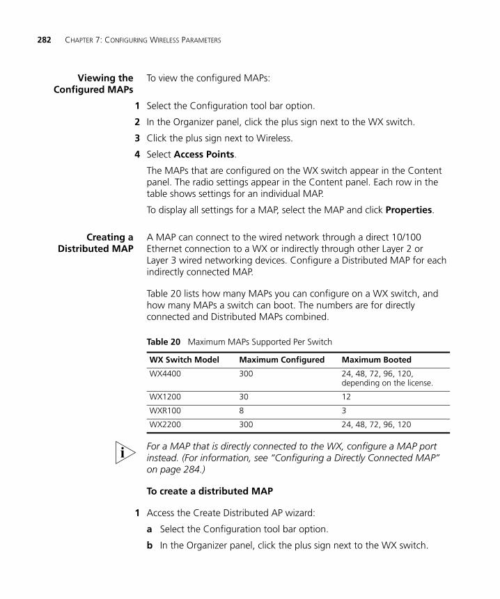
282 CHAPTER 7: CONFIGURING WIRELESS PARAMETERS
Viewing theConfigured MAPs
To view the configured MAPs:
1 Select the Configuration tool bar option.
2 In the Organizer panel, click the plus sign next to the WX switch.
3 Click the plus sign next to Wireless.
4 Select Access Points.
The MAPs that are configured on the WX switch appear in the Content panel. The radio settings appear in the Content panel. Each row in the table shows settings for an individual MAP.
To display all settings for a MAP, select the MAP and click Properties.
Creating aDistributed MAP
A MAP can connect to the wired network through a direct 10/100 Ethernet connection to a WX or indirectly through other Layer 2 or Layer 3 wired networking devices. Configure a Distributed MAP for each indirectly connected MAP.
Table 20 lists how many MAPs you can configure on a WX switch, and how many MAPs a switch can boot. The numbers are for directly connected and Distributed MAPs combined.
For a MAP that is directly connected to the WX, configure a MAP port instead. (For information, see “Configuring a Directly Connected MAP” on page 284.)
To create a distributed MAP
1 Access the Create Distributed AP wizard:
a Select the Configuration tool bar option.
b In the Organizer panel, click the plus sign next to the WX switch.
Table 20 Maximum MAPs Supported Per Switch
WX Switch Model Maximum Configured Maximum Booted
WX4400 300 24, 48, 72, 96, 120, depending on the license.
WX1200 30 12
WXR100 8 3
WX2200 300 24, 48, 72, 96, 120
Viewing and Configuring MAPs 283
c Click the plus sign next to Wireless.
d Select Access Points.
e In the Task List panel, select Distributed AP.
2 In the Name box, type a name (1 to 16 alphanumeric characters, with no spaces or tabs).
3 In the DAP Number box, specify the WX switch connection number the connection to this Distributed MAP. The range of valid connection numbers depends on the WX switch model:
For a WX4400, you can specify a number from 1 to 300.
For a WX1200, you can specify a number from 1 to 30.
For a WXR100, you can specify a number from 1 to 8.
4 In the Serial Number box, type the serial number of the MAP.
5 In the Fingerprint box, type the 16-digit hexadecimal number of the encryption fingerprint for the MAP. Use either of the following formats:
11:22:33:44:55:66:77:88:99:aa:bb:cc:dd:ee:ff:00
1122:3344:5566:7788:99aa:bbcc:ddee:ff00
The fingerprint for a MAP is the hash value of the public encryption key for the MAP. The fingerprint is displayed on a label on the back of the MAP, and is labeled RSA key. If the MAP is already installed and operating, use the CLI command display dap status command to display the fingerprint.
The fingerprint is used for secure communication between the WX switch and the MAP, and applies only to Distributed MAPs.
6 Click Next.
7 Select the MAP model from the MAP Model list.
8 To select the radio type for a single-radio model, click the MAP Radio Type box and select the radio type from the list:
11a—802.11a
11b—802.11b only
11g—802.11b/g
9 Click Next.
10 Configure the radios:
a To enable the radio, select Enabled.
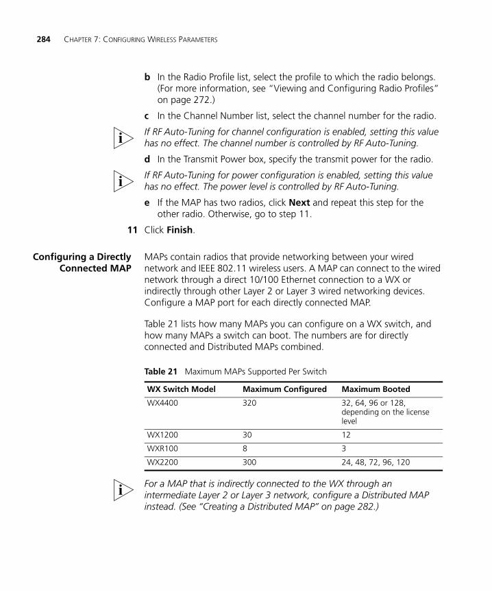
284 CHAPTER 7: CONFIGURING WIRELESS PARAMETERS
b In the Radio Profile list, select the profile to which the radio belongs. (For more information, see “Viewing and Configuring Radio Profiles” on page 272.)
c In the Channel Number list, select the channel number for the radio.
If RF Auto-Tuning for channel configuration is enabled, setting this value has no effect. The channel number is controlled by RF Auto-Tuning.
d In the Transmit Power box, specify the transmit power for the radio.
If RF Auto-Tuning for power configuration is enabled, setting this value has no effect. The power level is controlled by RF Auto-Tuning.
e If the MAP has two radios, click Next and repeat this step for the other radio. Otherwise, go to step 11.
11 Click Finish.
Configuring a DirectlyConnected MAP
MAPs contain radios that provide networking between your wired network and IEEE 802.11 wireless users. A MAP can connect to the wired network through a direct 10/100 Ethernet connection to a WX or indirectly through other Layer 2 or Layer 3 wired networking devices. Configure a MAP port for each directly connected MAP.
Table 21 lists how many MAPs you can configure on a WX switch, and how many MAPs a switch can boot. The numbers are for directly connected and Distributed MAPs combined.
For a MAP that is indirectly connected to the WX through an intermediate Layer 2 or Layer 3 network, configure a Distributed MAP instead. (See “Creating a Distributed MAP” on page 282.)
Table 21 Maximum MAPs Supported Per Switch
WX Switch Model Maximum Configured Maximum Booted
WX4400 320 32, 64, 96 or 128, depending on the license level
WX1200 30 12
WXR100 8 3
WX2200 300 24, 48, 72, 96, 120
Viewing and Configuring MAPs 285
You cannot configure any gigabit Ethernet port, or port 7 or 8 on a WX1200 switch, or port 1 on a WXR100 switch, as a MAP port. To manage a MAP on a WX4400 switch, configure a Distributed MAP connection on the switch. (See “Creating a Distributed MAP” on page 282.)
To configure a directly connected MAP
1 Access the Create Direct-Connect AP wizard:
a Select the Configuration tool bar option.
b In the Organizer panel, click the plus sign next to the WX switch.
c Click the plus sign next to Wireless.
d Select Access Points.
2 In the Task List panel, select Directly Connect AP.
3 Select the WX port the MAP will be connected to from the Available Ports drop-down list.
Configuring a directly connected MAP in a port converts the port to a MAP access port. If the port is a statically configured member of a VLAN, the port is removed from the VLAN.
4 Click Next.
5 Select the MAP model from the MAP Model list.
6 To select the radio type for a single-radio model, click the MAP Radio Type box and select the radio type from the list:
11a—802.11a
11b—802.11b only
11g—802.11b/g
7 Click Next.
The non-editable number (1 or 2) indicates the radio number on the MAP.
8 To select the radio type for a single-radio model, click the MAP Radio Type box and select the radio type from the list:
11a—802.11a
11b—802.11b only
11g—802.11b/g
9 Click Next.
286 CHAPTER 7: CONFIGURING WIRELESS PARAMETERS
10 Configure the radios:
a To enable the radio, select Enabled.
b In the Radio Profile list, select the profile to which the radio belongs. (For more information, see “Viewing and Configuring Radio Profiles” on page 272.)
c In the Channel Number list, select the channel number for the radio.
If RF Auto-Tuning for channel configuration is enabled, setting this value has no effect. The channel number is controlled by RF Auto-Tuning.
d In the Transmit Power box, specify the transmit power for the radio.
If RF Auto-Tuning for power configuration is enabled, setting this value has no effect. The power level is controlled by RF Auto-Tuning.
e If the MAP has two radios, click Next and repeat this step for the other radio. Otherwise, go to step 11.
11 Click Finish.
Setting Up APRedundancy
You can configure redundant WX connections for MAPs in the network.
Only AP models that have two Ethernet ports can support redundant direct connections. However, models with one Ethernet port can support redundant distributed connections.
WX4400 switches support indirect MAP connections only.
To set up AP redundancy:
1 Access the Setup AP Redundancy wizard:
a Select the Configuration tool bar option.
b In the Organizer panel, click the plus sign next to the WX switch.
c Click the plus sign next to Wireless.
d Select Access Points.
e In the Task List panel, select AP Redundancy.
The Setup AP redundancy wizard appears, listing the redundant connections for each MP.
2 Select the MAP for which you want to set up a redundant WX connection and click Add Connections.
a Under Select Bias, select either High or Low from the drop-down list.
Viewing and Configuring MAPs 287
Bias is the priority of one WX connection over other WX connections to a single MAP for booting, configuration, and data transfer. A configuration with a high bias has priority over a configuration for the same MAP with low bias. The default is High.
If the bias for all connections is the same, the MAP selects the switch that has the greatest capacity to add more active MAPs. For example, if an MAP is dual homed to two WX-4400 switches, and one of the switches has 50 active MAPs while the other switch has 60 active MAPs, the new MAP selects the switch that has only 50 active MAPs.
b The number of redundant connections available for each configured WX switch is listed. Select the WX switch the MAP will use for a redundant connection and click OK.
3 To remove all redundant connections for an MAP, select the MAP and click Clear Connections.
4 To create a direct redundant connection for an MAP, select the MAP, click Create, and select Direct Connection from the list.
a Select the WX switch to which the MAP is connected.
b Select the port to which the MAP is connected.
c Set the bias to High or Low.
d Select Enable POE to enable power over Ethernet on the port
e Click Finish.
5 To create a distributed redundant connection for an MAP, select the MAP, click Create, and select Distributed Connection from the list.
a Select the WX switch to which the MAP establishes a distributed connection.
b Set the bias to High or Low.
c Click Finish.
6 To modify a redundant connection for an MAP, select the MAP in the upper box, then select the connection in the lower box and click Properties.
288 CHAPTER 7: CONFIGURING WIRELESS PARAMETERS
Changing the MAPModel
To change the model number of an MAP
1 Access the Change AP Model wizard:
a Select the Configuration tool bar option.
b In the Organizer panel, click the plus sign next to the WX switch.
c Click the plus sign next to Wireless.
d Select Access Points.
e In the content panel, select the MAP whose model number you want to change.
f In the Task List panel, select AP model.
2 Select the new MAP model number from the drop-down list.
3 Click OK.
Changing the RadioType for an MAP
To change the radio type for an MAP:
1 Access the Change AP Model wizard:
a Select the Configuration tool bar option.
b In the Organizer panel, click the plus sign next to the WX switch.
c Click the plus sign next to Wireless.
d Select Access Points.
e In the content panel, select the MAP whose radio type you want to change.
f In the Task List panel, select AP radio type.
2 Select the radio type from the list:
11a—802.11a
11b—802.11b only
11g—802.11b/g
3 Click OK.
Viewing and Configuring MAPs 289
Changing theMAP-WX Security
Mode
To change the MAP-WX security mode for all Distributed MAPs, select the value from the Security Mode drop-down list:
None—Management traffic between Distributed MAPs and the WX is not encrypted, even for MAPs that support encryption.
Optional—Distributed MAPs can be managed by the switch even if they do not have encryption keys or their keys have not been verified by an administrator. Encryption is used for MAPs that support it.
Require—Distributed MAPs can be managed by the switch only if they have encryption keys and their keys have been verified by an administrator. If a MAP does not have an encryption key or the key has not been verified, the WX does not establish a management session with the MAP.
The setting applies to all Distributed MAPs booted and managed by the switch. A change to this setting affects only new management sessions established after deploying the change to the switch. The change does not affect existing sessions.
ConfiguringAdvanced MAP
Settings
After configuring a MAP, select the MAP and click Properties. 3WXM will display a configuration wizard that contains all of the configurable parameters for the MAP.
You also can edit values listed in the table by editing them in the table itself.
1 Access the MAP table:
a Select the Configuration tool bar option.
b In the Organizer panel, click the plus sign next to the WX switch.
c Click the plus sign next to Wireless.
d Select Access Points.
2 Select the MAP you want to modify and click Properties.
3 To change the Name, edit the string in the Name box.
4 To add Location information about the MAP (for example, “In the Conference Room”), enter text in the Location box.
5 To add Contact information about the MAP (for example, “Bob the IT Guy”), enter text in the Contact box.
6 To correct the serial number, edit the value in the Serial Number box.
290 CHAPTER 7: CONFIGURING WIRELESS PARAMETERS
7 To enter or correct the fingerprint, enter or edit the value in the Fingerprint box.
8 If you are configuring dual-homing support, in the Bias list, select High or Low.
Bias is the priority of one WX connection over other WX connections to a single MAP for booting, configuration, and data transfer. You can set the bias for a Distributed MAP to be low or high. A configuration with a high bias has priority over a configuration for the same MAP with low bias. The default is High.
If the bias for all connections is the same, the MAP selects the switch that has the greatest capacity to add more active MAPs. For example, if a MAP is dual homed to two WX4400 switches, and one of the switches has 50 active MAPs while the other switch has 60 active MAPs, the new MAP selects the switch that has only 50 active MAPs.
Bias applies only to WX switches that are indirectly attached to the MAP through an intermediate Layer 2 or Layer 3 network. A MAP always attempts to boot on MAP port 1 first, and if the MAP is directly attached to a WX switch on MAP port 1, it boots from that switch regardless of the bias settings.
9 To force the MAP to always download its software image from the WX switch instead of loading the image that is locally stored on the MAP, select Force Image Download. By default, the MAP loads its locally stored image unless the WX has a newer one.
A change to this option takes place the next time the MAP is restarted.
10 In the Enable Blink list, select Yes to enable LED blink mode or No to disable it.
When blink mode is enabled, the health and radio LEDs alternately blink green and amber, allowing you to visually identify a MAP. By default, blink mode is disabled.
11 In the Enable Firmware Update list, select Yes to automatically upgrade MAP boot firmware. The upgrade version of the firmware is loaded from a WX when the MAP is booting.
Select No to disable automatic firmware upgrading. Automatic firmware upgrading is enabled by default.
12 To add the MAP to a session load-balancing group, enter the group name in the Load Balance Group box.
Viewing and Configuring MAPs 291
13 To configure settings for a radio, click the 802.11g Radio or 802.11a Radio tab.
a To enable the radio, select Enabled.
b If the MAP model supports external antennas, select the location and model from the Antenna Location and Antenna Type boxes.
To meet regulatory requirements. you must ensure that the external antenna model you specify exactly matches the external antenna that is attached to the MAP's external antenna port.
c To indicate the coverage direction of the antenna, change the value in the Directionality of antenna box. The default value of 0 degrees directs the coverage to the right on the floor plan. For example, to move the coverage 90 degrees (so that the coverage area of the antenna faces downward as you view the floor plan), type 90 in the box.
You can verify and change the coverage direction after completing this wizard. To verify the coverage, display the floor plan where the MAP is located. The antenna direction is indicated by an arrow.
To show the RF coverage for the antenna, select the MAP, right-click, and select Display RF Coverage and the radio type from the drop-down list.
To adjust the coverage, select the MAP, right-click, and select Edit Properties from the drop-down list to display the Modify MAP or Modify DAP wizard. In the wizard, click the tab for the radio to display its configuration page, edit the value in the Antenna Direction box, and click OK.
3WXM assumes that the external antenna will be installed so that the front faces in the direction of coverage (not up or down), and so that the antenna cable connector faces down or up. 3WXM also assumes that the antenna does not provide any coverage behind itself.
The Antenna Type and Directionality of antenna boxes appear only if the MAP model supports an external antenna.
d In the Radio Profile list, select the profile to which the radio belongs. (For more information, see “Viewing and Configuring Radio Profiles” on page 272.)
e In the Channel Number list, select the channel number for the radio.
If RF Auto-Tuning for channel configuration is enabled, setting this value has no effect. The channel number is controlled by RF Auto-Tuning.
292 CHAPTER 7: CONFIGURING WIRELESS PARAMETERS
f In the Transmit Power box, specify the transmit power for the radio.
If RF Auto-Tuning for power configuration is enabled, setting this value has no effect. The power level is controlled by RF Auto-Tuning.
a To change the maximum power level RF Auto-Tuning can assign to the radio, select the power level from the Max. Transmit Power pull-down list.
The default power level is default, which means RF Auto-Tuning can assign up to the maximum power level allowed for the radio.
14 Click OK.
Viewing and Changing Radio Settings
You can configure MAP radio settings when you configure the MAPs. You also can view or change radio settings after the MAPs are configured.
Viewing RadioSettings
To view radio settings:
1 Select the Configuration tool bar option.
2 In the Organizer panel, click the plus sign next to the WX switch.
3 Click the plus sign next to Wireless.
4 Select Radios.
The radio settings appear in the Content panel. Each row in the table shows settings for an individual radio.
To display all settings for a radio, select the radio and click Properties.
Changing RadioSettings
To change radio settings:
1 Access the radio table:
a Select the Configuration tool bar option.
b In the Organizer panel, click the plus sign next to the WX switch.
c Click the plus sign next to Wireless.
d Select Radios.
2 To change basic radio settings, select the new values in the table. To change more advanced features, select the radio and click Properties.
Viewing and Changing RF Detection Settings 293
(For information about the radio parameters in the table, see step 10 on page 286. For information about the radio parameters in the Radio Properties wizard, see step 13 on page 291.)
3 If you edit settings in the table, click Save. If you configure settings in the Radio Properties wizard, clicking OK to close the wizard also saves the changes.
Viewing and Changing RF Detection Settings
This section contains procedures for configuring RF detection on an individual switch. For an overview of RF detection and for specific information about the configuration options, see “Configuring Wireless Parameters” on page 245.
The tasks available here allow you to configure entries for permit lists, the ignore list, and the black list. However, you must enter the SSID, Organizationally Unique Identifier (OUI), or MAC address you are adding to a list. To add a value to a list by selecting it, use the RF Detection window instead. (See “Detecting and Combatting Rogue Devices” on page 469.)
To convert a rogue into a third-party AP, see “Converting a Rogue into a Third Party AP” on page 482.
Viewing RF DetectionSettings
To view RF detection settings:
1 Select the Configuration tool bar option.
2 In the Organizer panel, click the plus sign next to the WX switch.
3 Click the plus sign next to Wireless.
4 Select RF Detection.
The RF detection settings appear in the Content panel.
Adding an Entry tothe Permitted Vendor
OUI List
To add an entry to the permitted vendor OUI list:
1 Access the RF detection settings:
a Select the Configuration tool bar option.
b In the Organizer panel, click the plus sign next to the WX switch.
294 CHAPTER 7: CONFIGURING WIRELESS PARAMETERS
c Click the plus sign next to Wireless.
d Select RF Detection.
2 In the Task List panel, select Vendor OUIs.
3 Select the device type(s):
Client
AP
4 Select the vendor from the Vendor drop-down list.
5 Select the specific OUIs you want to allow for the selected vendor. Go to step 9.
If the vendor or OUI is not listed, click Cancel, then select Permitted OUI Entry in the Task List panel. Go to step 6.
6 Edit the OUI in the Vendor OUI box.
7 Select the device type from the Type drop-down list: Client, AP, or All (both client and AP).
8 Click OK.
9 Click Add to move the OUIs to the Permitted OUI List.
10 Click OK.
Adding an Entry tothe Permitted SSID
List
To add an entry to the permitted SSID list:
1 Access the RF detection settings:
a Select the Configuration tool bar option.
b In the Organizer panel, click the plus sign next to the WX switch.
c Click the plus sign next to Wireless.
d Select RF Detection.
2 In the Task List panel, select Permitted SSID Entry.
3 Type the SSID name in the SSID box.
4 Click OK.
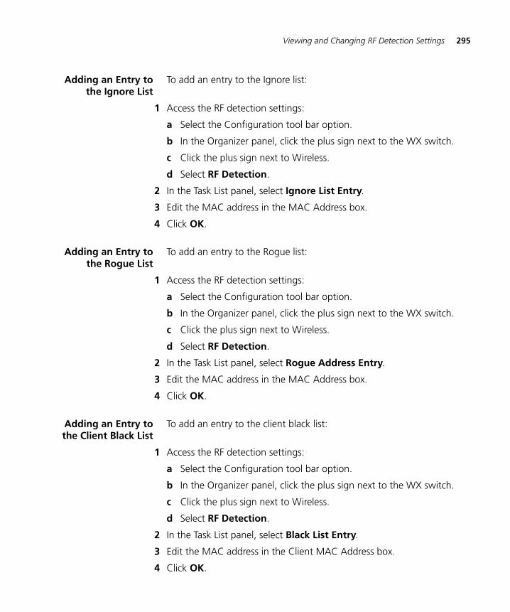
Viewing and Changing RF Detection Settings 295
Adding an Entry tothe Ignore List
To add an entry to the Ignore list:
1 Access the RF detection settings:
a Select the Configuration tool bar option.
b In the Organizer panel, click the plus sign next to the WX switch.
c Click the plus sign next to Wireless.
d Select RF Detection.
2 In the Task List panel, select Ignore List Entry.
3 Edit the MAC address in the MAC Address box.
4 Click OK.
Adding an Entry tothe Rogue List
To add an entry to the Rogue list:
1 Access the RF detection settings:
a Select the Configuration tool bar option.
b In the Organizer panel, click the plus sign next to the WX switch.
c Click the plus sign next to Wireless.
d Select RF Detection.
2 In the Task List panel, select Rogue Address Entry.
3 Edit the MAC address in the MAC Address box.
4 Click OK.
Adding an Entry tothe Client Black List
To add an entry to the client black list:
1 Access the RF detection settings:
a Select the Configuration tool bar option.
b In the Organizer panel, click the plus sign next to the WX switch.
c Click the plus sign next to Wireless.
d Select RF Detection.
2 In the Task List panel, select Black List Entry.
3 Edit the MAC address in the Client MAC Address box.
4 Click OK.
296 CHAPTER 7: CONFIGURING WIRELESS PARAMETERS
EnablingCountermeasures
To enable countermeasures:
1 Access the RF detection settings:
a Select the Configuration tool bar option.
b In the Organizer panel, click the plus sign next to the WX switch.
c Click the plus sign next to Wireless.
d Select RF Detection.
2 To enable countermeasures against rogues detected by radios managed by this profile, select one of the following from the Countermeasures Type pull-down list for the radio profile:
None—Radios do not use countermeasures. This is the default.
All—Radios use countermeasures against devices classified by MSS as rogues and against devices classified by MSS as interfering devices.
A rogue is a device that is in the 3Com network but does not belong there. An interfering device is not part of the 3Com network but also is not a rogue. MSS classifies a device as an interfering device if no client connected to the device has been detected communicating with any network entity listed in the forwarding database (FDB) of any WX switch in the Mobility Domain. Although the interfering device is not connected to your network, the device might be causing RF interference with MAP radios.
Rogue—Radios use countermeasures against devices classified by MSS as rogues, but do not use countermeasures against devices classified by MSS as interfering devices.
Countermeasures affect wireless service on a radio. When a MAP radio is sending countermeasures, the radio is disabled for use by network traffic, until the radio finishes sending the countermeasures.
Configured—Configures radios to attack only devices specified in the attack list on the switch (on-demand countermeasures). When this option is used, devices found to be rogues by other means, such as policy violations or by determining that the device is providing connectivity to the wired network, are not attacked.
3 Click Save.
To view or change other radio profile options, select the radio profile and click Properties.
Viewing and Changing RF Detection Settings 297
Enabling MAPSignatures
A MAP signature is a set of bits in a management frame sent by a MAP that identifies that MAP to MSS. If someone attempts to spoof management packets from a 3Com MAP, MSS can detect the spoof attempt.
1 Access the RF detection settings:
a Select the Configuration tool bar option.
b In the Organizer panel, click the plus sign next to the WX switch.
c Click the plus sign next to Wireless.
d Select RF Detection.
2 Select Enable AP Signature.
3 Click Save.

298 CHAPTER 7: CONFIGURING WIRELESS PARAMETERS
8 CONFIGURING AUTHENTICATION, AUTHORIZATION, AND ACCOUNTING PARAMETERS
This chapter describes how to view and configure the following Authentication, Authorization, and Accounting (AAA) parameters for WX switches:
Local database entries for AAA processing of administrator and network client access
RADIUS servers, for backend AAA processing of WX administrator access and network client access
Global 802.1X Settings
Network client access rules
WX administrator access rules
RADIUS proxy entries and 802.1Q mapping to provide AAA for clients of third-party APs
Location policies for overriding authorization parameters assigned by AAA to network clients
Mobility profiles for controlling network client access to specific MAP ports, Distributed MAPs, or wired authentication ports
Creating and Managing Users in the Local User Database
The WX switch contains a local database that can store user information for a 3Com Mobility System. You can use the local database to create users and authenticate them, or you can use the local database in conjunction with a RADIUS server. For example, although you might use a RADIUS server to manage most users, you could define IT staff as users in the local database in the event that the RADIUS server is unavailable.
300 CHAPTER 8: CONFIGURING AUTHENTICATION, AUTHORIZATION, AND ACCOUNTING PARAMETERS
You can create two types of users in the local database:
Named users — These users are authenticated by username and password and are assigned to specific VLANs. Users include administrators and network users. You can group these users by creating user groups, in order to simplify configuration.
MAC address users — These users are authenticated by a MAC address. For example, devices such as PDAs or cellular phones that do not support 802.1X authentication are identified when the WX switch discovers the MAC addresses of these devices from received frames. The MAC address is the username and is authenticated by the local database. You can group these users by creating user groups. MAC address users and user groups cannot be assigned administrative access to the WX switch.
In addition to username and password, you can configure authorization attributes for users. Authorization attributes specify the network resources the user can access. The most commonly used attribute is VLAN-Name, which specifies the VLAN to place the user in after they are authorized.
You can configure authorization attributes for individual users and for user groups. When you configure attributes for a user group, the attribute settings apply to all users in the group. However, if attributes are also configured for an individual user in the group, the values for the attributes configured for the individual user override the attribute values configured for the group.
You can configure groups for named users and groups for MAC users. A group cannot contain both named users and MAC users.
Viewing Users andGroups in the Local
Database
To view users and groups in the local database:
1 Select the Configuration tool bar option.
2 In the Organizer panel, click the plus sign next to the WX switch.
3 Click the plus sign next to AAA.
4 Select Local User Database.
The users and user groups configured in the local user database appear.
Creating and Managing Users in the Local User Database 301
Creating a NamedUser
To create a named user:
1 Access the Create Named User wizard:
a Select the Configuration tool bar option.
b In the Organizer panel, click the plus sign next to the WX switch.
c Click the plus sign next to AAA.
d Select Local User Database.
e In the Task List panel, select User.
2 In the Name box, type the name of the user (1 to 60 alphanumeric characters, with no spaces or tabs).
3 In the Password box, type the password for the user (1 to 80 alphanumeric characters, with no spaces or tabs). You must specify a password if you want the password to be encrypted in the configuration file.
4 In the User Group list, select a user group to assign the user to, if the group is already configured.
You do not need to assign a user to a user group. If you do select a user group, you only need to specify a password for the user. All other attributes are obtained from the user group.
5 To set authorization attributes for the user, click Next and go to step 6.
6 In the VLAN Name box, select or type the name of the VLAN that the user belongs to (1 to 16 alphanumeric characters, with no spaces or tabs). The WX switch will authorize the user for that VLAN. For more information on VLANs, see “Viewing and Configuring VLANs” on page 215.
If the user requires administrative access only, you do not need to specify a VLAN.
Otherwise, if you plan to set authorization attributes in another way, such as adding the user to a group or configuring default AAA attribute values for the SSID the user will access, click Finish.
7 In the attribute row you want to configure, click the Attribute Value column.
See Table 22 on page 305 for a description of user attributes and their values.
8 Type the new attribute value in lowercase characters. ACL names are case-sensitive.
302 CHAPTER 8: CONFIGURING AUTHENTICATION, AUTHORIZATION, AND ACCOUNTING PARAMETERS
9 Repeat step 5 through step 7 for each attribute value you want to change.
10 Click Finish.
Creating a UserGroup and Assigning
Users To It
To create a user group and assign users to it:
1 Access the Create Named User Group wizard:
a Select the Configuration tool bar option.
b In the Organizer panel, click the plus sign next to the WX switch.
c Click the plus sign next to AAA.
d Select Local User Database.
e In the Task List panel, select Named User Group.
2 To set authorization attributes for users in the group, click Next and go to step 3.
Otherwise, if you plan to set authorization attributes in another way, such as configuring default AAA attribute values for the SSID the user will access, click Finish.
3 In the VLAN Name box, select or type the VLAN that the user group belongs to (1 to 16 alphanumeric characters, with no spaces or tabs). The WX switch will authorize the users in this group for that VLAN. For more information on VLANs, see “Viewing and Configuring VLANs” on page 215.
4 In the attribute row you want to configure, click the Attribute Value column.
See Table 22 on page 305 for a description of user attributes and their values.
5 Type the new attribute value in lowercase characters. ACL names are case-sensitive.
6 Repeat step 4 through step 5 for each attribute value you want to change.
7 To add users to the group, click Next.
8 Select users in the Available Users list.
9 Click Add to move them to the Current Users list.
10 Click Finish.
Creating and Managing Users in the Local User Database 303
Creating a MAC User To create a MAC user:
1 When creating MAC address users, you configure authentication Access the Create MAC User wizard:
a Select the Configuration tool bar option.
b In the Organizer panel, click the plus sign next to the WX switch.
c Click the plus sign next to AAA.
d Select Local User Database.
e In the Task List panel, select MAC Address User.
2 In the User MAC Address box, type the MAC address for the user device, using colons (:) as delimiters. You must specify all 6 bytes of the MAC address.
3 In the MAC User Group list, select the MAC user group that the user device belongs to, if the group is already configured.
4 To set authorization attributes for the user, click Next and go to step 5.
Otherwise, if you plan to set authorization attributes in another way, such as adding the user to a group or configuring default AAA attribute values for the SSID the user will access, click Finish.
5 In the VLAN Name box, select or type the name of the VLAN that the user device belongs to (1 to 16 alphanumeric characters, with no spaces or tabs). The WX switch will authorize the user for that VLAN. For more information on VLANs, see “Viewing and Configuring VLANs” on page 215.
6 In the attribute row you want to configure, click the Attribute Value column.
See Table 22 on page 305 for a description of user attributes and their values.
7 Type the new attribute value in lowercase characters. ACL names are case-sensitive.
8 Repeat step 5 through step 7 for each attribute value you want to change.
9 Click Finish.
304 CHAPTER 8: CONFIGURING AUTHENTICATION, AUTHORIZATION, AND ACCOUNTING PARAMETERS
Creating a MAC UserGroup and Assigning
Users To It
To create a MAC user group and assign users to it:
1 Access the Create MAC User Group wizard:
a Select the Configuration tool bar option.
b In the Organizer panel, click the plus sign next to the WX switch.
c Click the plus sign next to AAA.
d Select Local User Database.
e In the Task List panel, select MAC User Group.
2 In the User Group Name box, type a name for the MAC address user group (1 to 60 alphanumeric characters, with no spaces or tabs).
3 To set authorization attributes for MAC addresses in the group, click Next and go to step 4.
Otherwise, if you plan to set authorization attributes in another way, such as configuring default AAA attribute values for the SSID the user will access, click Finish.
4 In the VLAN Name box, select or type the VLAN that the group belongs to (1 to 16 alphanumeric characters, with no spaces or tabs). The WX switch will authorize the MAC users in this group for that VLAN. For more information on VLANs, see “Viewing and Configuring VLANs” on page 215.
5 In the attribute row you want to configure, click the Attribute Value column.
See Table 22 on page 305 for a description of user attributes and their values.
6 Type the new attribute value in lowercase characters. ACL names are case-sensitive.
7 Repeat step 4 through step 6 for each attribute value you want to change.
8 To add MAC addresses to the group, click Next.
9 Select users in the Available MAC Address Users list.
10 Click Add to move them to the Current MAC Address Users list.
11 Click Finish.
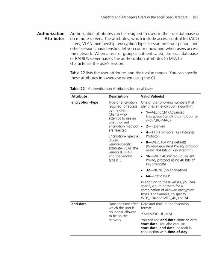
Creating and Managing Users in the Local User Database 305
AuthorizationAttributes
Authorization attributes can be assigned to users in the local database or on remote servers. The attributes, which include access control list (ACL) filters, VLAN membership, encryption type, session time-out period, and other session characteristics, let you control how and when users access the network. When a user or group is authenticated, the local database or RADIUS server passes the authorization attributes to MSS to characterize the user’s session.
Table 22 lists the user attributes and their value ranges. You can specify these attributes in lowercase when using the CLI.
Table 22 Authentication Attributes for Local Users
Attribute Description Valid Value(s)
encryption-type Type of encryption required for access by the client. Clients who attempt to use an unauthorized encryption method are rejected.
Encryption-Type is a 3Com vendor-specific attribute (VSA). The vendor ID is 43, and the vendor type is 3.
One of the following numbers that identifies an encryption algorithm:
1—AES_CCM (Advanced Encryption Standard using Counter with CBC-MAC)
2—Reserved
4—TKIP (Temporal Key Integrity Protocol)
8—WEP_104 (the default) (Wired-Equivalent Privacy protocol using 104 bits of key strength)
16—WEP_40 (Wired-Equivalent Privacy protocol using 40 bits of key strength)
32—NONE (no encryption)
64—Static WEP
In addition to these values, you can specify a sum of them for a combination of allowed encryption types. For example, to specify WEP_104 and WEP_40, use 24.
end-date Date and time after which the user is no longer allowed to be on the network.
Date and time, in the following format:
YY/MM/DD-HH:MM
You can use end-date alone or with start-date. You also can use start-date, end-date, or both in conjunction with time-of-day.
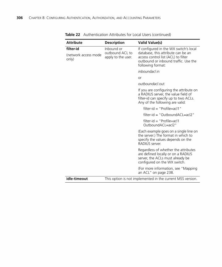
306 CHAPTER 8: CONFIGURING AUTHENTICATION, AUTHORIZATION, AND ACCOUNTING PARAMETERS
filter-id
(network access mode only)
Inbound or outbound ACL to apply to the user.
If configured in the WX switch’s local database, this attribute can be an access control list (ACL) to filter outbound or inbound traffic. Use the following format:
inboundacl.in
or
outboundacl.out
If you are configuring the attribute on a RADIUS server, the value field of filter-id can specify up to two ACLs. Any of the following are valid:
filter-id = "Profile=acl1"
filter-id = "OutboundACL=acl2"
filter-id = "Profile=acl1 OutboundACL=acl2"
(Each example goes on a single line on the server.) The format in which to specify the values depends on the RADIUS server.
Regardless of whether the attributes are defined locally or on a RADIUS server, the ACLs must already be configured on the WX switch.
(For more information, see “Mapping an ACL” on page 238.
idle-timeout This option is not implemented in the current MSS version.
Table 22 Authentication Attributes for Local Users (continued)
Attribute Description Valid Value(s)
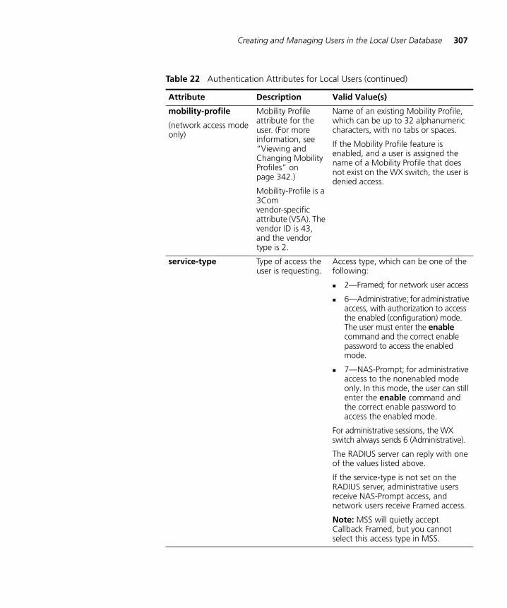
Creating and Managing Users in the Local User Database 307
mobility-profile
(network access mode only)
Mobility Profile attribute for the user. (For more information, see “Viewing and Changing Mobility Profiles” on page 342.)
Mobility-Profile is a 3Com vendor-specific attribute (VSA). The vendor ID is 43, and the vendor type is 2.
Name of an existing Mobility Profile, which can be up to 32 alphanumeric characters, with no tabs or spaces.
If the Mobility Profile feature is enabled, and a user is assigned the name of a Mobility Profile that does not exist on the WX switch, the user is denied access.
service-type Type of access the user is requesting.
Access type, which can be one of the following:
2—Framed; for network user access
6—Administrative; for administrative access, with authorization to access the enabled (configuration) mode. The user must enter the enable command and the correct enable password to access the enabled mode.
7—NAS-Prompt; for administrative access to the nonenabled mode only. In this mode, the user can still enter the enable command and the correct enable password to access the enabled mode.
For administrative sessions, the WX switch always sends 6 (Administrative).
The RADIUS server can reply with one of the values listed above.
If the service-type is not set on the RADIUS server, administrative users receive NAS-Prompt access, and network users receive Framed access.
Note: MSS will quietly accept Callback Framed, but you cannot select this access type in MSS.
Table 22 Authentication Attributes for Local Users (continued)
Attribute Description Valid Value(s)
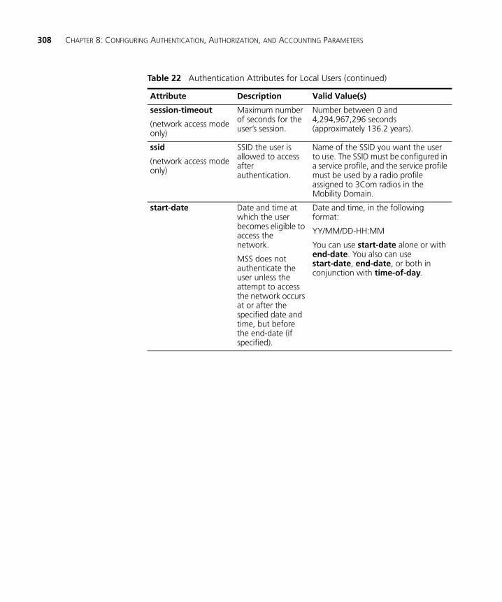
308 CHAPTER 8: CONFIGURING AUTHENTICATION, AUTHORIZATION, AND ACCOUNTING PARAMETERS
session-timeout
(network access mode only)
Maximum number of seconds for the user’s session.
Number between 0 and 4,294,967,296 seconds (approximately 136.2 years).
ssid
(network access mode only)
SSID the user is allowed to access after authentication.
Name of the SSID you want the user to use. The SSID must be configured in a service profile, and the service profile must be used by a radio profile assigned to 3Com radios in the Mobility Domain.
start-date Date and time at which the user becomes eligible to access the network.
MSS does not authenticate the user unless the attempt to access the network occurs at or after the specified date and time, but before the end-date (if specified).
Date and time, in the following format:
YY/MM/DD-HH:MM
You can use start-date alone or with end-date. You also can use start-date, end-date, or both in conjunction with time-of-day.
Table 22 Authentication Attributes for Local Users (continued)
Attribute Description Valid Value(s)
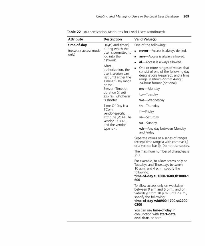
Creating and Managing Users in the Local User Database 309
time-of-day
(network access mode only)
Day(s) and time(s) during which the user is permitted to log into the network.
After authorization, the user’s session can last until either the Time-Of-Day range or the Session-Timeout duration (if set) expires, whichever is shorter.
Time-Of-Day is a 3Com vendor-specific attribute (VSA). The vendor ID is 43, and the vendor type is 4.
One of the following:
never—Access is always denied.
any—Access is always allowed.
al—Access is always allowed.
One or more ranges of values that consist of one of the following day designations (required), and a time range in hhmm-hhmm 4-digit 24-hour format (optional):
mo—Monday
tu—Tuesday
we—Wednesday
th—Thursday
fr—Friday
sa—Saturday
su—Sunday
wk—Any day between Monday and Friday
Separate values or a series of ranges (except time ranges) with commas (,) or a vertical bar (|). Do not use spaces.
The maximum number of characters is 253.
For example, to allow access only on Tuesdays and Thursdays between 10 a.m. and 4 p.m., specify the following: time-of-day tu1000-1600,th1000-1600
To allow access only on weekdays between 9 a.m and 5 p.m., and on Saturdays from 10 p.m. until 2 a.m., specify the following: time-of-day wk0900-1700,sa2200-0200
You can use time-of-day in conjunction with start-date, end-date, or both.
Table 22 Authentication Attributes for Local Users (continued)
Attribute Description Valid Value(s)
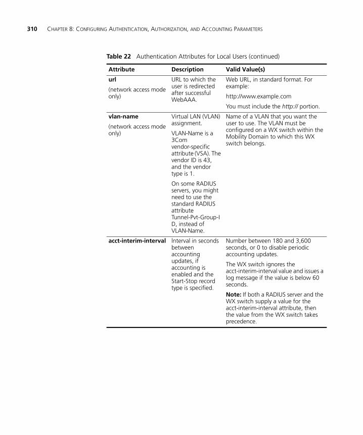
310 CHAPTER 8: CONFIGURING AUTHENTICATION, AUTHORIZATION, AND ACCOUNTING PARAMETERS
url
(network access mode only)
URL to which the user is redirected after successful WebAAA.
Web URL, in standard format. For example:
http://www.example.com
You must include the http:// portion.
vlan-name
(network access mode only)
Virtual LAN (VLAN) assignment.
VLAN-Name is a 3Com vendor-specific attribute (VSA). The vendor ID is 43, and the vendor type is 1.
On some RADIUS servers, you might need to use the standard RADIUS attribute Tunnel-Pvt-Group-ID, instead of VLAN-Name.
Name of a VLAN that you want the user to use. The VLAN must be configured on a WX switch within the Mobility Domain to which this WX switch belongs.
acct-interim-interval lnterval in seconds between accounting updates, if accounting is enabled and the Start-Stop record type is specified.
Number between 180 and 3,600 seconds, or 0 to disable periodic accounting updates.
The WX switch ignores the acct-interim-interval value and issues a log message if the value is below 60 seconds.
Note: If both a RADIUS server and the WX switch supply a value for the acct-interim-interval attribute, then the value from the WX switch takes precedence.
Table 22 Authentication Attributes for Local Users (continued)
Attribute Description Valid Value(s)
Viewing and Configuring RADIUS Settings 311
Viewing and Configuring RADIUS Settings
Remote Authentication Dial-In User Service (RADIUS) is a client-server security protocol that provides authentication, authorization, and accounting for network users and devices. A RADIUS server stores user profiles, which include usernames, passwords, and other user attributes. After defining RADIUS servers, define RADIUS server groups (named sets of RADIUS servers). You must create at least one server group.
RADIUS server groups can authenticate administrators and network users. You can specify up to four RADIUS server groups for AAA services in a 3Com Mobility System.
Although you can use the local database on the WX switch to authenticate users, 3Com recommends using RADIUS to accommodate the large number of users in an enterprise network.
For information about the RADIUS attributes supported by MSS, see the Wireless LAN Switch and Controller Configuration Guide.
Viewing RADIUSSettings, Servers, and
Server Groups
To view RADIUS settings, servers, and server groups:
1 Select the Configuration tool bar option.
2 In the Organizer panel, click the plus sign next to the WX switch.
3 Click the plus sign next to AAA.
4 Select RADIUS.
The RADIUS servers, server groups, and default settings appear.
Creating a RADIUSServer
To create a RADIUS server:
1 Access the Create RADIUS Server wizard:
a Select the Configuration tool bar option.
b In the Organizer panel, click the plus sign next to the WX switch.
c Click the plus sign next to AAA.
d Select RADIUS.
e In the Task List panel, select RADIUS Server.
312 CHAPTER 8: CONFIGURING AUTHENTICATION, AUTHORIZATION, AND ACCOUNTING PARAMETERS
2 In the Name box, type the name of an existing RADIUS server (1 to 64 alphanumeric characters, with no spaces or tabs). Do not use the same name for a RADIUS server and a RADIUS server group.
3 In the IP Address box, type the IP address for the RADIUS server, in dotted decimal notation.
3WXM suggests the name of a server group to place the server in. The server group is required because AAA rules refer to server groups, not to individual servers.
4 Click Next.
5 If you need to change port numbers or timers, go to step 6. Otherwise, go to step 11.
6 In the Authentication Port box, specify the UDP destination port to which the WX switch listens for authentication and authorization. The default port is 1812.
7 In the Accounting Port box, specify the UDP destination port to which the WX switch listens for accounting. The default port is 1813.
8 In the Timeout box, specify how long (1 to 65,535 seconds) the WX switch must wait for a RADIUS server to respond before retransmitting. The default is 5 seconds.
9 In the Retry Count box, specify how many retransmissions (1 to 100) are sent for a RADIUS request. The default is 2.
10 In the Dead Time box, specify how long (0 to 1440 minutes) the WX switch waits before attempting to reach an unresponsive RADIUS server. The default is 0 minutes.
11 In the Key box, type the password (also known as a shared secret key) used to authenticate to the RADIUS server (1 to 32 characters long, with no spaces or tabs).
You must provide the same password that is defined on the RADIUS server.
12 In the Authorization Password box, type the password used for outbound authentication and authorization to a RADIUS server (1 to 32 alphanumeric characters, with no spaces or tabs).
Providing an authorization password is required only for users whose devices are authenticated by their MAC addresses or for last-resort users, neither of which have a regular username or password. The default authorization password is 3Com.
Viewing and Configuring RADIUS Settings 313
Changing the password applies both to MAC users and to last-resort users.
All MAC address-authenticated users or last-resort users must share the same authorization password on the RADIUS server.
13 Click Next.
Modifying a RADIUSServer
To modify a RADIUS server:
1 In the content panel, select the RADIUS server you want to modify and click Properties.
2 In the IP Address box, type the IP address for the RADIUS server, in dotted decimal notation.
3 In the Key box, type the password (also known as a shared secret key) used to authenticate to the RADIUS server (1 to 32 characters long, with no spaces or tabs).
You must provide the same password that is defined on the RADIUS server.
4 In the Timeout box, specify how long (1 to 65,535 seconds) the WX switch must wait for a RADIUS server to respond before retransmitting. The default is 5 seconds.
5 In the Authentication Port box, specify the UDP destination port to which the WX switch listens for authentication and authorization. The default port is 1812.
6 In the Accounting Port box, specify the UDP destination port to which the WX switch listens for accounting. The default port is 1813.
7 In the Retry Count box, specify how many retransmissions (1 to 100) are sent for a RADIUS request. The default is 2.
8 In the Dead Time box, specify how long (0 to 1440 minutes) the WX switch waits before attempting to reach an unresponsive RADIUS server. The default is 0 minutes.
9 In the Authorization Password box, type the password used for outbound authentication and authorization to a RADIUS server (1 to 32 alphanumeric characters, with no spaces or tabs).
Providing an authorization password is required only for users whose devices are authenticated by their MAC addresses or for non-802.1X users of third-party APs. Neither of these user types has a regular username or password. The default authorization password is 3Com.
314 CHAPTER 8: CONFIGURING AUTHENTICATION, AUTHORIZATION, AND ACCOUNTING PARAMETERS
Changing the password applies both to MAC users and to last-resort users.
All MAC address-authenticated users or last-resort users must share the same authorization password on the RADIUS server.
10 Click OK.
Creating a RADIUSServer Group
A server group is a group of one to four RADIUS servers. Server groups enable RADIUS server redundancy by allowing another server to be used if the first server is unavailable. You must create at least one server group, even if you are using only one RADIUS server. You can specify the order in which servers are used for authentication. You can also specify load balancing, which uses all servers in a group using a round-robin algorithm.
1 Access the Create RADIUS Server Group wizard:
a Select the Configuration tool bar option.
b In the Organizer panel, click the plus sign next to the WX switch.
c Click the plus sign next to AAA.
d Select RADIUS.
e In the Task List panel, select RADIUS Server Group.
2 In the Name box, type the name of the RADIUS server group (1 to 32 alphanumeric characters, with no spaces or tabs). Do not use the same name for a RADIUS server and a server group.
3 Click Next.
4 To enable load balancing in the server group, select Load Balance.
If you enable load balancing, a round-robin approach is used to balance the load among servers. Authentication and accounting requests for a given user are always sent to the same server. Each new authentication event uses the next server in the list.
If load balancing is not enabled, the first server in the list is contacted first. If the first server does not respond, the second server in the list is contacted.
5 To add RADIUS servers to the server group, select the servers in the Available RADIUS Servers list and click Add.
Viewing and Configuring RADIUS Settings 315
6 To reorder the servers, select a server and click Up or Down.
If load balancing is enabled, the first AAA request goes to the first RADIUS server in the list. The second AAA request goes to the second RADIUS server in the list, and so on, until the end of the list is reached, after which the first server in the list is used again. Any server that does not respond is skipped. If none of the servers responds, the WX goes to the next method in the method list.
7 Click Next.
When you add a RADIUS server to a RADIUS server group, all RADIUS timers for the server group are restarted.
Changing DefaultRADIUS Settings
You can set default values for certain RADIUS parameters that apply to RADIUS servers and server groups you create for an individual WX. The following RADIUS parameters, except system IP address, are defined with default values, which you can change:
Timeout (generally set for only troubleshooting purposes)
Retry count (generally set for only troubleshooting purposes)
Dead time
Key
Authorization password
Use of the system IP address for the WX switch as the source address for RADIUS packets from the switch
When you create a new RADIUS server, the default settings apply to the new server.
To change default values for RADIUS parameters
1 Access the RADIUS defaults:
a Select the Configuration tool bar option.
b In the Organizer panel, click the plus sign next to the WX switch.
c Click the plus sign next to AAA.
d Select RADIUS.
e In the Task List panel, select RADIUS Defaults.
316 CHAPTER 8: CONFIGURING AUTHENTICATION, AUTHORIZATION, AND ACCOUNTING PARAMETERS
2 In the Timeout box, specify how long WX switch must wait (1 to 65,535 seconds) for a RADIUS server to respond before retransmitting. The default is 5 seconds.
3 In the Retry Count box, specify the number of transmission attempts (1 to 100) for a RADIUS request. The default is 3.
4 In the Dead Time box, specify the amount of time (0 to 1440 minutes) that must elapse before the WX switch attempts to reach an unresponsive RADIUS server. The default is 0 minutes.
When the dead time is set to 0, and there are two or more RADIUS servers in a RADIUS server group, authentication starts with the first server in the group, unless there are two or more RADIUS servers and load sharing is configured, in which case authentication starts by trying a server in round-robin style.
5 In the Key box, type the password (also known as a shared secret key) used to authenticate to the RADIUS server.
You must provide the same password that is defined on the RADIUS server. The password can be 1 to 64 characters long, with no spaces or tabs.
6 In the Authorization Password box, type the password used for outbound authentication and authorization to a RADIUS server. The authorization password can be 1 to 32 alphanumeric characters long, with no spaces or tabs.
Providing an authorization password is required only for users whose devices are authenticated by their MAC addresses or for last-resort users, neither of which have a regular username or password. The default authorization password is 3Com.
Changing the password applies both to MAC users and to last-resort users.
All MAC address-authenticated users or last-resort users must share the same authorization password on the RADIUS server.
7 Click Save.
8 To make RADIUS packets from the WX switch use the system IP address as the source IP address, select Use System IP Address in the content panel.
Viewing and Configuring Global 802.1X Settings 317
Configuring RADIUSSystem Accounting
You can configure RADIUS system accounting in 3WXM. When system accounting is enabled, an Accounting-On message (Acct-Status-Type = 7) is sent to the specified RADIUS server group when the WX switch starts, and an Accounting-Off message (Acct-Status-Type = 8) to the RADIUS server when the WX switch is administratively shut down.
Accounting-Off messages are sent only when the WX switch is administratively shut down, not when a critical failure causes the WX switch to reset. The WX switch does not wait for a RADIUS server to acknowledge the Accounting-Off message; the switch makes one attempt to send the Accounting-Off message, then shuts down.
To configure RADIUS system accounting:
1 Access the RADIUS accounting properties:
a Select the Configuration tool bar option.
b In the Organizer panel, click the plus sign next to the WX switch.
c Click the plus sign next to AAA.
d Select RADIUS.
e In the Task List panel, select System Accounting.
2 Select the server group(s) in the Available RADIUS Server Groups list and click Add.
The Accounting-On and Accounting-Off messages generated by the WX switch are sent to the selected server group(s).
3 Click OK.
Viewing and Configuring Global 802.1X Settings
The IEEE 802.1X standard provides an authentication framework that supports a variety of methods for authenticating and authorizing network access for wired or wireless users. You can configure 802.1X authentication parameters for an individual WX or for a domain policy.
CAUTION: 802.1X parameter settings are global for all SSIDs configured on the switch.
Viewing Global802.1X Settings
To view global 802.1X settings:
1 Select the Configuration tool bar option.
2 In the Organizer panel, click the plus sign next to the WX switch.
318 CHAPTER 8: CONFIGURING AUTHENTICATION, AUTHORIZATION, AND ACCOUNTING PARAMETERS
3 Click the plus sign next to AAA.
4 Select 802.1X.
The global 802.1X settings appear.
Changing Global802.1X Settings
To change global 802.1x settings:
1 Access the 802.1X settings:
a Select the Configuration tool bar option.
b In the Organizer panel, click the plus sign next to the WX switch.
c Click the plus sign next to AAA.
d Select 802.1X.
2 To enable 802.1X authentication for all wired authentication ports on the WX switch, select System Authentication Control.
To disable 802.1X authentication for all wired authentication ports, clear System Authentication Control. By default, 802.1X authentication is enabled.
3 To specify the number of seconds the WX switch waits before attempting reauthentication, specify the timeout value (0 to 65,535 seconds) in the Quiet Period Timeout box. The default is 60 seconds.
4 To specify the number of seconds the WX switch waits before retransmitting an Extensible Authentication Protocol over LAN (EAPoL) packet, specify the timeout value (1 to 65,535 seconds) in the Retransmit Timeout box. The default is 5 seconds.
5 To specify the number of seconds before the WX switch times out an authentication session with an 802.1X client (supplicant), specify the timeout value (1 to 65,535 seconds) in the Supplicant Timeout box. The default is 30 seconds.
6 To specify the number of seconds before the WX switch times out a request to an authentication server, specify the timeout value (1 to 65,535 seconds) in the Authentication Server Timeout box. The default is 30 seconds.
7 To set the maximum number of times the WX switch retransmits an EAP request to the client before timing out the authentication session, specify the value (0 to 10) in the Maximum Requests box. The default is 2 attempts.
Viewing and Configuring Global 802.1X Settings 319
To support SSIDs that have both 802.1X and static WEP clients, MSS sends a maximum of two ID requests, even if this parameter is set to a higher value. Setting the parameter to a higher value does affect all other types of EAP messages.
8 To enable encryption key information to be sent to the client after authentication in EAPoL-Key PDUs, select Key Transmit.
The WX switch sends EAPoL key messages after successfully authenticating the client and receiving authorization attributes for the client. If the client is using dynamic Wired-Equivalent Privacy protocol (WEP), the EAPoL key messages are sent immediately after authorization.
To disable this option, clear Key Transmit. By default, this option is enabled.
9 To enable reauthentication of 802.1X clients, select Reauthentication.
To disable reauthentication, clear Reauthentication. By default, reauthentication is enabled.
10 To specify the number of reauthentication requests the WX switch attempts before a client becomes unauthorized, specify the value (1 to 10) in the Reauthentication Attempts box. The default is 2 attempts.
If the number of reauthentications for a wired authentication client is greater than the maximum number of reauthentications allowed, MSS sends an EAP failure packet to the client and removes the client from the network. However, MSS does not remove a wireless client from the network under these circumstances.
11 To specify the number of seconds before reauthentication is attempted, specify the timeout value, from 60 to 1,641,600 seconds (19 days), in the Reauthentication Period box. The default is 3600 seconds (one hour).
MSS reauthenticates dynamic WEP clients based on the reauthentication timer. MSS also reauthenticates WPA clients if the clients use the WEP-40 or WEP-104 cipher. For each dynamic WEP client or WPA client using a WEP cipher, the reauthentication timer is set to the lesser of the global setting or the value returned by the AAA server with the rest of the authorization attributes for that client.
12 To enable WEP key rolling (rotation) of the broadcast and multicast WEP keys, select WEP Key Rolling.
13 To specify the time to wait before rotating the WEP key, specify the value, from 30 to 1,641,600 seconds, (19 days) in the WEP Key Rolling Period box. The default is 3600 seconds (one hour).
320 CHAPTER 8: CONFIGURING AUTHENTICATION, AUTHORIZATION, AND ACCOUNTING PARAMETERS
14 To specify the number of seconds MSS retains session information for Bonded Auth™ (bonded authentication) purposes for an authenticated machine while waiting for the 802.1X client on the machine to start (re)authentication for the user, specify the value, from 1 to 300 seconds, in the Bonded Period box. The default is 0 seconds.
15 Click Save.
Viewing and Configuring 802.1X Network Access Rules
This section describes how to view and configure 802.1X rules for user network access.
To configure other types of network access rules, see the following:
“Viewing and Configuring MAC Network Access Rules” on page 324
“Viewing and Configuring WebAAA Network Access Rules” on page 327
“Viewing and Configuring Last-Resort Network Access Rules” on page 330
To configure access rules for administrative access to the WX itself, see “Viewing and Configuring WX Administrator Access Rules” on page 332.
This section assumes that you are familiar with the AAA options in MSS. For detailed information, see the “Configuring AAA for Network Users” chapter of the Wireless LAN Switch and Controller Configuration Guide.
Viewing 802.1XNetwork Access Rules
To view 802.1X network access rules:
1 Select the Configuration tool bar option.
2 In the Organizer panel, click the plus sign next to the WX switch.
3 Click the plus sign next to AAA.
4 Select 802.1X Access Rules.
The configured 802.1X network access rules appear.
Viewing and Configuring 802.1X Network Access Rules 321
Creating an 802.1XNetwork Access Rule
If the network user name matches the userglob in an 802.1X access rule, the WX switch attempts to authenticate the client using 802.1X.
1 Access the Create 802.1X Network Access wizard:
a Select the Configuration tool bar option.
b In the Organizer panel, click the plus sign next to the WX switch.
c Click the plus sign next to AAA.
d Select 802.1X Access Rules.
e In the Task List panel, select 802.1X Network Access.
2 Specify whether the rule is for wireless access to an SSID or access through a wired authentication port:
If the rule is for access to an SSID, do one of the following:
To match on any SSID name, leave the value any in the SSID box.
To match only on a specific SSID name, select or type the name in the SSID box.
If the rule is for access through a wired authentication port, select Wired.
CAUTION: The default SSID name any matches on all SSID names. If the SSID box contains any and you do not change the SSID name, the authentication rule allows clients who match the userglob to access any SSID.
3 Type the userglob that is allowed to use 802.1X to access the SSID or wired authentication port.
A user glob is a string containing wildcards that matches on one or more user names. Type a full or partial username to be matched during authentication (1 to 80 alphanumeric characters, with no spaces or tabs). The format of a user glob depends on the client type and EAP method.
For Windows domain clients using Protected EAP (PEAP), the user glob is in the format Windows_domain_name\username. The Windows domain name is the NetBIOS domain name and must be specified in capital letters. For example, EXAMPLE\sydney, or EXAMPLE\*.*, which specifies all usernames whose usernames contain periods.
322 CHAPTER 8: CONFIGURING AUTHENTICATION, AUTHORIZATION, AND ACCOUNTING PARAMETERS
For EAP with Transport Layer Security (EAP-TLS) clients, the format is username@domain_name. For example, [email protected] specifies the user sydney in the domain name example.com. The *@marketing.example.com glob specifies all users in the marketing department at example.com. The user glob [email protected] specifies the user sydney in the engineering department at example.com.
4 Click Next.
5 Select the EAP type from the EAP Type drop-down list:
EAP-MD5—Extensible Authentication Protocol (EAP) with message-digest algorithm 5. Select this protocol for wired authentication clients.
Uses challenge-response to compare hashes.
Provides no encryption or integrity checking for the connection.
The EAP-MD5 option does not work with Microsoft wired authentication clients.
PEAP—Protected EAP with Microsoft Challenge Handshake Authentication Protocol Version 2 (MS-CHAP-V2). Select this protocol for wireless clients.
Uses TLS for encryption and data integrity checking.
Provides MS-CHAP-V2 mutual authentication.
Only the server side of the connection needs a certificate.
Local EAP-TLS—EAP with TLS.
Provides mutual authentication, integrity-protected negotiation, and key exchange.
Requires X.509 public key certificates on both sides of the connection.
Provides encryption and integrity checking for the connection.
Cannot be used with RADIUS server authentication (requires user information to be in the local database of the switch)
Pass-Through—No protocol is used by the WX. 3Com Mobility System Software (MSS) sends the EAP processing to a RADIUS server.
If you select PEAP, the EAP Sub-Protocol is MS-CHAPV2. For other protocols, there is no the EAP Sub-Protocol to select.
6 Click Next.
Viewing and Configuring 802.1X Network Access Rules 323
7 If the authentication rule is disabled, select Enabled.
When a rule is disabled, 3WXM does not add it to the configuration.
8 Select the authentication method(s) in the Available RADIUS Server Groups list and click Add.
An authentication method specifies where the switch will look for user information to authenticate users. You can select a RADIUS server group, LOCAL (the local user database for the switch), or both.
MSS tries the methods in the order they appear in the Current RADIUS Server Groups list. To reorder the methods, select a method and click Up or Down.
If you specify a RADIUS server group as the first method and a user is denied access by the RADIUS server, no authentication and authorization are attempted with the other methods specified in the list.
If you specify LOCAL as the first method and a user is not in the local user database on the WX, authentication and authorization are attempted with a RADIUS server group if one is defined in the method list.
The authentication methods you select are also used for authorization.
9 Click Next.
10 To enable an accounting rule for the SSID, select Enabled.
By default, accounting rules you configure in 3WXM are disabled, which means 3WXM does not add the rules to the configuration.
11 Select one of the following record options:
Select Start-Stop to specify that records are sent at the start of a session and the end of a session.
Select Stop-Only to specify that records are sent only at the end of a session.
12 Select the accounting method(s) in the Available RADIUS Server Groups list and click Add.
The options and processing are the same as those for authentication methods. (See step 8.)
13 Click Finish.
324 CHAPTER 8: CONFIGURING AUTHENTICATION, AUTHORIZATION, AND ACCOUNTING PARAMETERS
Viewing and Configuring MAC Network Access Rules
MAC network access rules allow users onto the network by authenticating their MAC addresses instead of their user names.
During log on, if the username does not match an 802.1X authentication rule, but the MAC address of the user’s NIC or Voice-over-IP (VoIP) phone and the SSID (if wireless) do match a MAC authentication rule, MSS checks the RADIUS server group or local database for matching user information. If the MAC address (and password, if on a RADIUS server) matches, MSS grants access. Otherwise, MSS attempts the fallthru authentication type, which can be Web, Open Access (last-resort), or none.
This section assumes that you are familiar with the AAA options in MSS. For detailed information, see the “Configuring AAA for Network Users” chapter of the Wireless LAN Switch and Controller Configuration Guide.
Viewing MACNetwork Access Rules
To view MAC network access rules:
1 Select the Configuration tool bar option.
2 In the Organizer panel, click the plus sign next to the WX switch.
3 Click the plus sign next to AAA.
4 Select MAC Access Rules.
The configured MAC network access rules appear.
Creating a MACNetwork Access Rule
To create a MAC network access rule:
1 Access the Create MAC Network Access wizard:
a Select the Configuration tool bar option.
b In the Organizer panel, click the plus sign next to the WX switch.
c Click the plus sign next to AAA.
d Select MAC Access Rules.
e In the Task List panel, select MAC Network Access.
Viewing and Configuring MAC Network Access Rules 325
2 Specify whether the rule is for wireless access to an SSID or access through a wired authentication port:
If the rule is for access to an SSID, do one of the following:
To match on any SSID name, leave the value any in the SSID box.
To match only on a specific SSID name, select or type the name in the SSID box.
If the rule is for access through a wired authentication port, select Wired.
CAUTION: The default SSID name any matches on all SSID names. If the SSID box contains any and you do not change the SSID name, the authentication rule allows clients who match the MAC address glob to access any SSID.
3 In the User Glob box, type a full or partial username to be matched during authentication.
MAC addresses must be specified with colons as the delimiters (for example, 00:11:22:33:44:55). You can use wildcards by specifying an asterisk (*) in MAC addresses. The following lists examples of using wildcards in MAC addresses:
* (all MAC addresses)
00:*
00:01:*
00:01:02*
00:01:02:03:*
00:01:02:03:04:*
00:01:02:03:04:0*
4 Click Next.
5 If the authentication rule is disabled, select Enabled.
When a rule is disabled, 3WXM does not add it to the configuration.
6 Select the authentication method(s) in the Available RADIUS Server Groups list and click Add.
An authentication method specifies where the switch will look for user information to authenticate users. You can select a RADIUS server group, LOCAL (the local user database for the switch), or both.
326 CHAPTER 8: CONFIGURING AUTHENTICATION, AUTHORIZATION, AND ACCOUNTING PARAMETERS
MSS tries the methods in the order they appear in the Current RADIUS Server Groups list. To reorder the methods, select a method and click Up or Down.
If you specify a RADIUS server group as the first method and a user is denied access by the RADIUS server, no authentication and authorization are attempted with the other methods specified in the list.
If you specify LOCAL as the first method and a user is not in the local user database on the WX, authentication and authorization are attempted with a RADIUS server group if one is defined in the method list.
The authentication methods you select are also used for authorization.
7 Click Next.
8 To enable this accounting rule for the SSID, select Enabled.
By default, accounting rules you configure in 3WXM are disabled, which means 3WXM does not add the rules to the configuration.
9 Select one of the following record options:
Select Start-Stop to specify that records are sent at the start of a session and the end of a session.
Select Stop-Only to specify that records are sent only at the end of a session.
10 Select the accounting method(s) in the Available RADIUS Server Groups list and click Add.
The options and processing are the same as those for authentication methods. (See step 6.)
11 Click Finish.
Viewing and Configuring WebAAA Network Access Rules 327
Viewing and Configuring WebAAA Network Access Rules
Web AAA allows network users to access the network by logging on a web page.
When a user attempts to access a web page over the network, the WX switch intercepts the HTTP or HTTPS request and serves a login Web page to the user. The user enters the username and password, and MSS checks the RADIUS server group or local database for matching user information. If the username and password match, MSS redirects the user to the web page she requested. Otherwise, MSS denies access to the user.
The fallthru access type for the SSID or wired authentication port must be set to Web. Otherwise, the web access rule will not take effect.
A web access rule is not used if the username matches on the user glob or MAC address glob in an 802.1X or MAC access rule, and the rule also matches on the SSID or wired authentication port through which the user is trying to access the network. In this case, the 802.1X or MAC rule is used instead.
Web Portal WebAAA replaces the WebAAA implementation in MSS Version 3.x. The previous implementation is deprecated beginning in MSS Version 4.0. During upgrade from MSS Version 3.x, your 3.x WebAAA configuration is automatically converted to a Web Portal WebAAA configuration.
This section assumes that you are familiar with the AAA options in MSS. For detailed information, see the “Configuring AAA for Network Users” chapter of the Wireless LAN Switch and Controller Configuration Guide.
Viewing Web AAANetwork Access Rules
To view Web AAA network access rules:
1 Select the Configuration tool bar option.
2 In the Organizer panel, click the plus sign next to the WX switch.
3 Click the plus sign next to AAA.
4 Select Web Access Rules.
The configured Web network access rules appear.
328 CHAPTER 8: CONFIGURING AUTHENTICATION, AUTHORIZATION, AND ACCOUNTING PARAMETERS
Creating a Web AAANetwork Access Rule
To create a Web AAA network access rule:
1 Access the Create Web Network Access wizard:
a Select the Configuration tool bar option.
b In the Organizer panel, click the plus sign next to the WX switch.
c Click the plus sign next to AAA.
d Select Web Access Rules.
2 In the Task List panel, select Web Network Access.
3 Specify whether the rule is for wireless access to an SSID or access through a wired authentication port:
If the rule is for access to an SSID, do one of the following:
To match on any SSID name, leave the value any in the SSID box.
To match only on a specific SSID name, select or type the name in the SSID box.
If the rule is for access through a wired authentication port, select Wired.
CAUTION: The default SSID name any matches on all SSID names. If the SSID box contains any and you do not change the SSID name, the authentication rule allows clients who match the userglob to access any SSID.
4 Type the userglob that is allowed to use Web AAA to access the SSID or wired authentication port.
A user glob is a string containing wildcards that matches on one or more user names. Type a full or partial username to be matched during authentication (1 to 80 alphanumeric characters, with no spaces or tabs). The format of a user glob depends on the client type and EAP method.
For Windows domain clients using Protected EAP (PEAP), the user glob is in the format Windows_domain_name\username. The Windows domain name is the NetBIOS domain name and must be specified in capital letters. For example, EXAMPLE\sydney, or EXAMPLE\*.*, which specifies all usernames whose usernames contain periods.
Viewing and Configuring WebAAA Network Access Rules 329
For EAP with Transport Layer Security (EAP-TLS) clients, the format is username@domain_name. For example, [email protected] specifies the user sydney in the domain name example.com. The *@marketing.example.com glob specifies all users in the marketing department at example.com. The user glob [email protected] specifies the user sydney in the engineering department at example.com.
5 Click Next.
6 If the authentication rule is disabled, select Enabled.
When a rule is disabled, 3WXM does not add it to the configuration.
7 Select the authentication method(s) in the Available RADIUS Server Groups list and click Add.
An authentication method specifies where the switch will look for user information to authenticate users. You can select a RADIUS server group, LOCAL (the local user database for the switch), or both.
MSS tries the methods in the order they appear in the Current RADIUS Server Groups list. To reorder the methods, select a method and click Up or Down.
If you specify a RADIUS server group as the first method and a user is denied access by the RADIUS server, no authentication and authorization are attempted with the other methods specified in the list.
If you specify LOCAL as the first method and a user is not in the local user database on the WX, authentication and authorization are attempted with a RADIUS server group if one is defined in the method list.
The authentication methods you select are also used for authorization.
8 Click Next.
9 To enable this accounting rule for the SSID, select Enabled.
By default, accounting rules you configure in 3WXM are disabled, which means 3WXM does not add the rules to the configuration.
10 Select one of the following record options:
Select Start-Stop to specify that records are sent at the start of a session and the end of a session.
Select Stop-Only to specify that records are sent only at the end of a session.
330 CHAPTER 8: CONFIGURING AUTHENTICATION, AUTHORIZATION, AND ACCOUNTING PARAMETERS
11 Select the accounting method(s) in the Available RADIUS Server Groups list and click Add.
The options and processing are the same as those for authentication methods. (See step 7.)
12 Click Finish.
Viewing and Configuring Last-Resort Network Access Rules
Last resort access allows users to access the network without entering a username or password.
This section assumes that you are familiar with the AAA options in MSS. For detailed information, see the “Configuring AAA for Network Users” chapter of the Wireless LAN Switch and Controller Configuration Guide.
Viewing Last-ResortNetwork Access Rules
To view last-resort network access rules:
1 Select the Configuration tool bar option.
2 In the Organizer panel, click the plus sign next to the WX switch.
3 Click the plus sign next to AAA.
4 Select Last Resort Access Rules.
The configured last-resort network access rules appear.
Creating a Last-ResortNetwork Access Rule
To create a last-resort network access rule:
1 Access the Create Last Resort Network Access wizard:
a Select the Configuration tool bar option.
b In the Organizer panel, click the plus sign next to the WX switch.
c Click the plus sign next to AAA.
d Select Last Resort Access Rules.
e In the Task List panel, select Last Resort Network Access.
Viewing and Configuring Last-Resort Network Access Rules 331
2 Specify whether the rule is for wireless access to an SSID or access through a wired authentication port:
If the rule is for access to an SSID, do one of the following:
To match on any SSID name, leave the value any in the SSID box.
To match only on a specific SSID name, select or type the name in the SSID box.
If the rule is for access through a wired authentication port, select Wired.
CAUTION: The default SSID name any matches on all SSID names. If the SSID box contains any and you do not change the SSID name, the authentication rule allows clients who match the userglob to access any SSID.
3 Click Next.
4 If the authentication rule is disabled, select Enabled.
When a rule is disabled, 3WXM does not add it to the switch’s configuration.
5 Select the authentication method(s) in the Available RADIUS Server Groups list and click Add.
An authentication method specifies where the switch will look for user information to authenticate users. You can select a RADIUS server group, LOCAL (the switch’s local user database), or both.
MSS tries the methods in the order they appear in the Current RADIUS Server Groups list. To reorder the methods, select a method and click Up or Down.
If you specify a RADIUS server group as the first method and a user is denied access by the RADIUS server, no authentication and authorization are attempted with the other methods specified in the list.
If you specify LOCAL as the first method and a user is not in the local user database on the WX, authentication and authorization are attempted with a RADIUS server group if one is defined in the method list.
The authentication methods you select are also used for authorization.
6 Click Next.
332 CHAPTER 8: CONFIGURING AUTHENTICATION, AUTHORIZATION, AND ACCOUNTING PARAMETERS
7 To enable this accounting rule for the SSID, select Enabled.
By default, accounting rules you configure in 3WXM are disabled, which means 3WXM does not add the rules to the switch’s configuration.
8 Select one of the following record options:
Select Start-Stop to specify that records are sent at the start of a session and the end of a session.
Select Stop-Only to specify that records are sent only at the end of a session.
9 Select the accounting method(s) in the Available RADIUS Server Groups list and click Add.
The options and processing are the same as those for authentication methods. (See step 5.)
10 Click Finish.
Viewing and Configuring WX Administrator Access Rules
MSS supports administrative access to a WX switch through the serial console port or through the network. Connections through the network use Telnet or SSH.
This section assumes that you are familiar with the AAA options for administrative access. For detailed information, see the “Configuring AAA for Administrative and Local Access” chapter of the Wireless LAN Switch and Controller Configuration Guide.
Viewing WXAdministrator Access
Rules
To view WX administrator access rules:
1 Select the Configuration tool bar option.
2 In the Organizer panel, click the plus sign next to the WX switch.
3 Click the plus sign next to AAA.
4 Select Admin Access Rules.
The configured administrative access rules appear.
Viewing and Configuring WX Administrator Access Rules 333
Creating an AccessRule for Console
Access
To create an access rule for console access:
1 Access the Create Console Admin User wizard:
a Select the Configuration tool bar option.
b In the Organizer panel, click the plus sign next to the WX switch.
c Click the plus sign next to AAA.
d Select Admin Access Rules.
e In the Task List panel, select Console Access.
2 Type the userglob that is allowed to access the switch through the console port.
3 Click Next.
4 If the authentication rule is disabled, select Enabled.
When a rule is disabled, 3WXM does not add it to the configuration.
5 Select the authentication method(s) in the Available RADIUS Server Groups list and click Add.
An authentication method specifies where the switch will look for user information to authenticate users. You can select a RADIUS server group, LOCAL (the local user database for the switch), or both.
MSS tries the methods in the order they appear in the Current RADIUS Server Groups list. To reorder the methods, select a method and click Up or Down.
If you specify a RADIUS server group as the first method and a user is denied access by the RADIUS server, no authentication and authorization are attempted with the other methods specified in the list.
If you specify LOCAL as the first method and a user is not in the local user database on the WX, authentication and authorization are attempted with a RADIUS server group if one is defined in the method list.
The authentication methods you select are also used for authorization.
6 Click Next.
334 CHAPTER 8: CONFIGURING AUTHENTICATION, AUTHORIZATION, AND ACCOUNTING PARAMETERS
7 To enable this accounting rule for the SSID, select Enabled.
By default, accounting rules you configure in 3WXM are disabled, which means 3WXM does not add the rules to the configuration.
8 Select one of the following record options:
Select Start-Stop to specify that records are sent at the start of a session and the end of a session.
Select Stop-Only to specify that records are sent only at the end of a session.
9 Select the accounting method(s) in the Available RADIUS Server Groups list and click Add.
The options and processing are the same as those for authentication methods. (See step 5.)
10 Click Finish.
Creating an AccessRule for Telnet or SSH
Access
To create an access rule for Telnet or SSH access:
1 Access the Create Admin User wizard:
a Select the Configuration tool bar option.
b In the Organizer panel, click the plus sign next to the WX switch.
c Click the plus sign next to AAA.
d Select Admin Access Rules.
e In the Task List panel, select Admin Access.
2 Type the userglob that is allowed to access the switch through Telnet or SSH.
3 Click Next.
4 If the authentication rule is disabled, select Enabled.
When a rule is disabled, 3WXM does not add it to the configuration.
5 Select the authentication method(s) in the Available RADIUS Server Groups list and click Add.
An authentication method specifies where the switch will look for user information to authenticate users. You can select a RADIUS server group, LOCAL (the local user database for the switch), or both.
Viewing and Configuring WX Administrator Access Rules 335
MSS tries the methods in the order they appear in the Current RADIUS Server Groups list. To reorder the methods, select a method and click Up or Down.
If you specify a RADIUS server group as the first method and a user is denied access by the RADIUS server, no authentication and authorization are attempted with the other methods specified in the list.
If you specify LOCAL as the first method and a user is not in the local user database on the WX, authentication and authorization are attempted with a RADIUS server group if one is defined in the method list.
The authentication methods you select are also used for authorization.
6 Click Next.
7 To enable this accounting rule for the SSID, select Enabled.
By default, accounting rules you configure in 3WXM are disabled, which means 3WXM does not add the rules to the configuration.
8 Select one of the following record options:
Select Start-Stop to specify that records are sent at the start of a session and the end of a session.
Select Stop-Only to specify that records are sent only at the end of a session.
9 Select the accounting method(s) in the Available RADIUS Server Groups list and click Add.
The options and processing are the same as those for authentication methods. (See step 5.)
10 Click Finish.
336 CHAPTER 8: CONFIGURING AUTHENTICATION, AUTHORIZATION, AND ACCOUNTING PARAMETERS
Viewing and Configuring AAA Support for Third-Party AP Users
A WX switch can provide network access for users associated with a third-party AP that has authenticated the users with RADIUS. You can connect a third-party AP to a WX switch and configure the WX to provide authorization for clients who authenticate and access the network through the AP.
Configure a proxy access rule for the AP.
Add a RADIUS proxy entry for the AP. The proxy entry specifies the IP address of the AP and the UDP ports on which the WX switch listens for RADIUS access-requests and stop-accounting records from the AP.
Specify the WX port connected to the third-party AP.
For information about configuration requirements on the third-party AP, see the “Configuring AAA for Users of Third-Party APs” section in the “Configuring AAA for Network Users” chapter of the Wireless LAN Switch and Controller Configuration Guide.
Viewing Settings forThird-Party AP AAA
Support
To view settings for third-party AP AAA support:
1 Select the Configuration tool bar option.
2 In the Organizer panel, click the plus sign next to the WX switch.
3 Click the plus sign next to AAA.
4 Select Third Party APs.
The configured settings appear.
Creating a ProxyAccess Rule
To create a proxy access rule:
1 Access the Create Proxy User wizard:
a Select the Configuration tool bar option.
b In the Organizer panel, click the plus sign next to the WX switch.
c Click the plus sign next to AAA.
d Select Third Party APs.
e In the Task List panel, select Proxy Access.
2 Type the userglob that is expected access the SSID.
Viewing and Configuring AAA Support for Third-Party AP Users 337
For the userglob, type a full or partial username to be matched during authentication (1 to 80 alphanumeric characters, with no spaces or tabs). The format of a user glob depends on the client type and EAP method.
For Windows domain clients using Protected EAP (PEAP), the user glob is in the format Windows_domain_name\username. The Windows domain name is the NetBIOS domain name and must be specified in capital letters. For example, EXAMPLE\sydney, or EXAMPLE\*.*, which specifies all usernames whose usernames contain periods.
For EAP with Transport Layer Security (EAP-TLS) clients, the format is username@domain_name. For example, [email protected] specifies the user sydney in the domain name example.com. The *@marketing.example.com glob specifies all users in the marketing department at example.com. The user glob [email protected] specifies the user sydney in the engineering department at example.com.
3 Optionally, edit the name in the SSID box.
CAUTION: The default SSID name any matches on all SSID names. If the SSID box contains any and you do not change the SSID name, the rule allows clients who match the userglob to access any SSID.
4 Select the authentication method(s) in the Available RADIUS Server Groups list and click Add.
An authentication method specifies where the switch will look for user information to authenticate users. You can select a RADIUS server group, LOCAL (the local user database for the switch), or both.
MSS tries the methods in the order they appear in the Current RADIUS Server Groups list. To reorder the methods, select a method and click Up or Down.
If you specify a RADIUS server group as the first method and a user is denied access by the RADIUS server, no authentication and authorization are attempted with the other methods specified in the list.
If you specify LOCAL as the first method and a user is not in the local user database on the WX, authentication and authorization are attempted with a RADIUS server group if one is defined in the method list.
The authentication methods you select are also used for authorization.
5 Click Finish.
338 CHAPTER 8: CONFIGURING AUTHENTICATION, AUTHORIZATION, AND ACCOUNTING PARAMETERS
Configuring a RADIUSProxy for a Client
To configure a RADIUS proxy for a client:
1 Access the Create RADIUS Proxy Client wizard:
a Select the Configuration tool bar option.
b In the Organizer panel, click the plus sign next to the WX switch.
c Click the plus sign next to AAA.
d Select Third Party APs.
e In the Task List panel, select RADIUS Proxy Client.
2 Type the IP address of the third-party AP and click Next.
3 To change the UDP port number on which the WX switch will listen for RADIUS access-requests from the AP, edit the number in the Authentication Port box.
4 To change the UDP port number on which the WX switch will listen for RADIUS stop-accounting records from the AP, edit the number in the Accounting Port box.
5 Type the key, which is the shared secret configured on the RADIUS servers. MSS uses the shared secret to authenticate and encrypt RADIUS communication.
6 Click Finish.
Specifying the WXPort Connected to the
Third-Party AP
To specify the WX port connected to the third-party AP:
1 Access the Create RADIUS Proxy Client wizard:
a Select the Configuration tool bar option.
b In the Organizer panel, click the plus sign next to the WX switch.
c Click the plus sign next to AAA.
d Select Third Party APs.
e In the Task List panel, select 802.1Q Mapping.
2 Select the WX ports that are connected to the third-party AP and click Add.
3 Click Finish.
Viewing and Changing Location Policy Rules 339
Viewing and Changing Location Policy Rules
During the login process, the AAA authorization process is started immediately after clients are authenticated to use the WX switch. During authorization, MSS assigns the user to a VLAN and applies optional user attributes, such as a session timeout value and one or more security ACL filters.
A location policy is a set of rules that enables you to locally set or change authorization attributes for a user after the user is authorized by AAA, without making changes to the AAA server. For example, you might want to enforce VLAN membership and security ACL policies on a particular WX based on a client’s organization or physical location, or assign a VLAN to users who have no AAA assignment. For these situations, you can configure the location policy on the switch.
You can use a location policy to locally set or change the Filter-Id and VLAN-Name authorization attributes obtained from AAA.
Conditions within a rule are ANDed. All conditions in the rule must match in order for MSS to take the specified action. If the location policy contains multiple rules, MSS compares the user information to the rules one at a time, in the order the rules appear in the configuration file, beginning with the rule at the top of the list. MSS continues comparing until a user matches all conditions in a rule or until there are no more rules.
Any authorization attributes not changed by the location policy remain active.
Each WX switch can have one location policy. The location policy consists of a set of rules. Each rule contains conditions, and an action to perform if all conditions in the rule match. The location policy can contain up to 150 rules.
Viewing LocationPolicy Rules
To view location policy rules:
1 Select the Configuration tool bar option.
2 In the Organizer panel, click the plus sign next to the WX switch.
3 Click the plus sign next to AAA.
4 Select Location Policy.
The configured location policy rules appear.
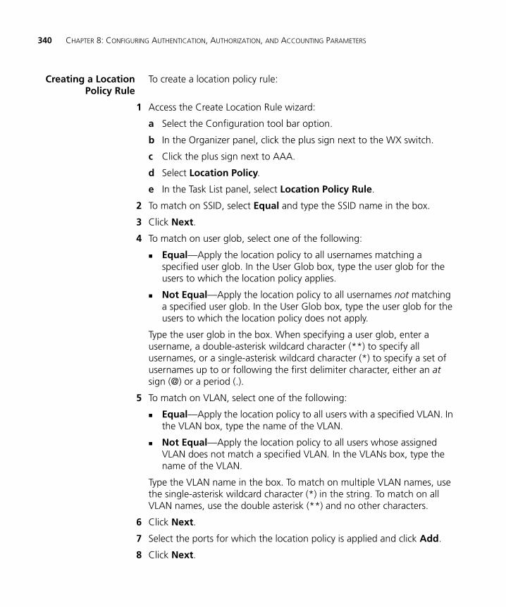
340 CHAPTER 8: CONFIGURING AUTHENTICATION, AUTHORIZATION, AND ACCOUNTING PARAMETERS
Creating a LocationPolicy Rule
To create a location policy rule:
1 Access the Create Location Rule wizard:
a Select the Configuration tool bar option.
b In the Organizer panel, click the plus sign next to the WX switch.
c Click the plus sign next to AAA.
d Select Location Policy.
e In the Task List panel, select Location Policy Rule.
2 To match on SSID, select Equal and type the SSID name in the box.
3 Click Next.
4 To match on user glob, select one of the following:
Equal—Apply the location policy to all usernames matching a specified user glob. In the User Glob box, type the user glob for the users to which the location policy applies.
Not Equal—Apply the location policy to all usernames not matching a specified user glob. In the User Glob box, type the user glob for the users to which the location policy does not apply.
Type the user glob in the box. When specifying a user glob, enter a username, a double-asterisk wildcard character (**) to specify all usernames, or a single-asterisk wildcard character (*) to specify a set of usernames up to or following the first delimiter character, either an at sign (@) or a period (.).
5 To match on VLAN, select one of the following:
Equal—Apply the location policy to all users with a specified VLAN. In the VLAN box, type the name of the VLAN.
Not Equal—Apply the location policy to all users whose assigned VLAN does not match a specified VLAN. In the VLANs box, type the name of the VLAN.
Type the VLAN name in the box. To match on multiple VLAN names, use the single-asterisk wildcard character (*) in the string. To match on all VLAN names, use the double asterisk (**) and no other characters.
6 Click Next.
7 Select the ports for which the location policy is applied and click Add.
8 Click Next.
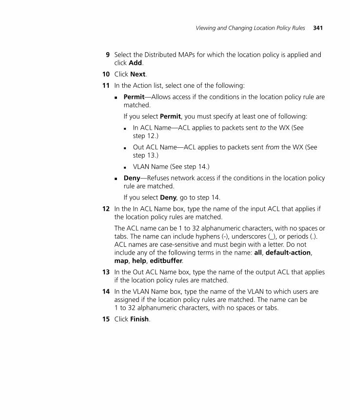
Viewing and Changing Location Policy Rules 341
9 Select the Distributed MAPs for which the location policy is applied and click Add.
10 Click Next.
11 In the Action list, select one of the following:
Permit—Allows access if the conditions in the location policy rule are matched.
If you select Permit, you must specify at least one of following:
In ACL Name—ACL applies to packets sent to the WX (See step 12.)
Out ACL Name—ACL applies to packets sent from the WX (See step 13.)
VLAN Name (See step 14.)
Deny—Refuses network access if the conditions in the location policy rule are matched.
If you select Deny, go to step 14.
12 In the In ACL Name box, type the name of the input ACL that applies if the location policy rules are matched.
The ACL name can be 1 to 32 alphanumeric characters, with no spaces or tabs. The name can include hyphens (-), underscores (_), or periods (.). ACL names are case-sensitive and must begin with a letter. Do not include any of the following terms in the name: all, default-action, map, help, editbuffer.
13 In the Out ACL Name box, type the name of the output ACL that applies if the location policy rules are matched.
14 In the VLAN Name box, type the name of the VLAN to which users are assigned if the location policy rules are matched. The name can be 1 to 32 alphanumeric characters, with no spaces or tabs.
15 Click Finish.
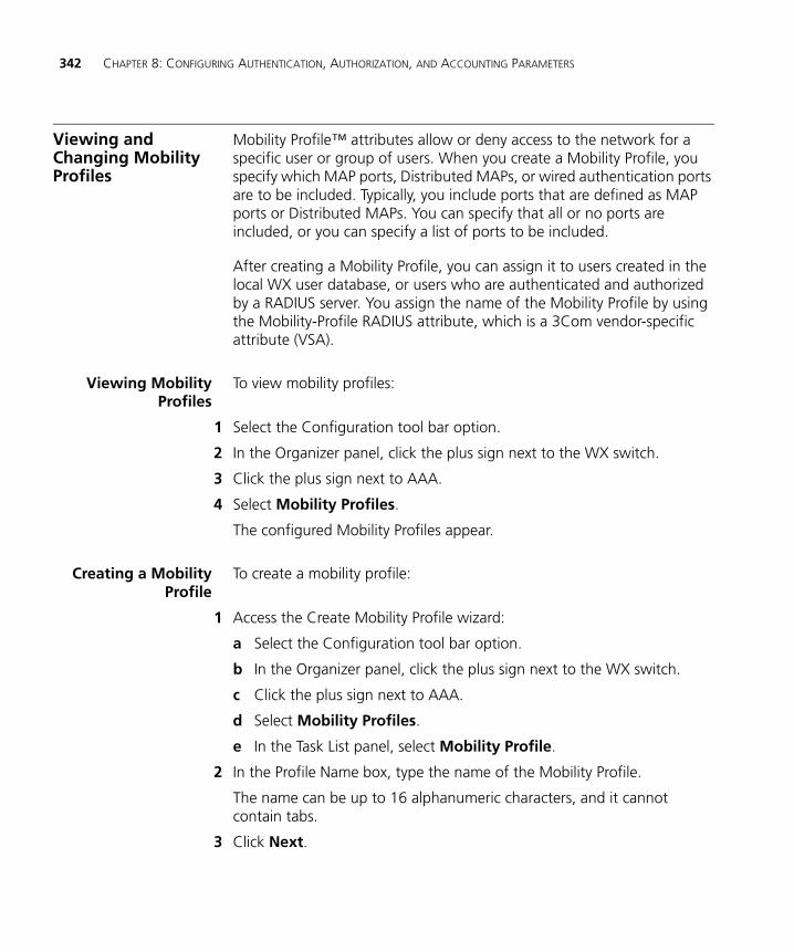
342 CHAPTER 8: CONFIGURING AUTHENTICATION, AUTHORIZATION, AND ACCOUNTING PARAMETERS
Viewing and Changing Mobility Profiles
Mobility Profile™ attributes allow or deny access to the network for a specific user or group of users. When you create a Mobility Profile, you specify which MAP ports, Distributed MAPs, or wired authentication ports are to be included. Typically, you include ports that are defined as MAP ports or Distributed MAPs. You can specify that all or no ports are included, or you can specify a list of ports to be included.
After creating a Mobility Profile, you can assign it to users created in the local WX user database, or users who are authenticated and authorized by a RADIUS server. You assign the name of the Mobility Profile by using the Mobility-Profile RADIUS attribute, which is a 3Com vendor-specific attribute (VSA).
Viewing MobilityProfiles
To view mobility profiles:
1 Select the Configuration tool bar option.
2 In the Organizer panel, click the plus sign next to the WX switch.
3 Click the plus sign next to AAA.
4 Select Mobility Profiles.
The configured Mobility Profiles appear.
Creating a MobilityProfile
To create a mobility profile:
1 Access the Create Mobility Profile wizard:
a Select the Configuration tool bar option.
b In the Organizer panel, click the plus sign next to the WX switch.
c Click the plus sign next to AAA.
d Select Mobility Profiles.
e In the Task List panel, select Mobility Profile.
2 In the Profile Name box, type the name of the Mobility Profile.
The name can be up to 16 alphanumeric characters, and it cannot contain tabs.
3 Click Next.
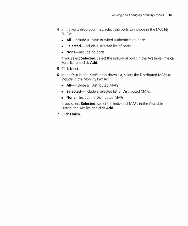
Viewing and Changing Mobility Profiles 343
4 In the Ports drop-down list, select the ports to include in the Mobility Profile:
All—Include all MAP or wired authentication ports.
Selected—Include a selected list of ports.
None—Include no ports.
If you select Selected, select the individual ports in the Available Physical Ports list and click Add.
5 Click Next.
6 In the Distributed MAPs drop-down list, select the Distributed MAPs to include in the Mobility Profile:
All—Include all Distributed MAPs.
Selected—Include a selected list of Distributed MAPs.
None—Include no Distributed MAPs.
If you select Selected, select the individual MAPs in the Available Distributed APs list and click Add.
7 Click Finish.

344 CHAPTER 8: CONFIGURING AUTHENTICATION, AUTHORIZATION, AND ACCOUNTING PARAMETERS
9 CONFIGURING WX SWITCHES REMOTELY
You can use 3WXM Services running in your corporate network to configure WX switches in remote offices. The following remote configuration scenarios are supported:
Drop ship—3WXM Services running in the corporate network can configure a WXR100 switch shipped directly to a remote office. This option does not require any preconfiguration of the switch.
Staged—You can stage any model of switch by preconfiguring IP connectivity and enabling auto-config, then sending the switch to the remote office. The switch contacts 3WXM Services in the corporate network to complete its configuration.
The drop ship option is supported only for the WXR100. The staged option is supported for all switch models. Both options require 3WXM Services. If you know a serial number for a switch, you can create a complete configuration for the switch in 3WXM. When the switch requests its configuration from 3WXM, 3WXM sends the configuration for that serial number. If you do not know the serial number, you can upload the partially configured switch into 3WXM, finish its configuration, then deploy the completed configuration back to the switch.
346 CHAPTER 9: CONFIGURING WX SWITCHES REMOTELY
How Remote WX Configuration Works
Drop Ship (WXR100Only)
1 The WXR100 is shipped directly to the remote office where it will be deployed.
2 The network administrator at the corporate office preconfigures the switch in a 3WXM network plan. The switch configuration must have a name for the switch, the model must be WXR100, and the serial number must match the serial number for the switch. The configuration should also include all other settings required for the deployment, including MAP configuration, SSIDs, AAA settings, and so on.
If enabled to do so, 3WXM can give a switch another switch’s configuration even though the serial number does not match. However, this capability is used only for replacing a failed switch with another switch of the same model, in a network containing only one WX switch. (See “Replacing a Switch and Reusing its Configuration” on page 356.)
3 Someone at the remote office where the switch is delivered physically installs the switch by connecting port 1 to the network. If the switch will manage a directly connected MAP, the MAP needs to be physically installed and connected by an Ethernet cable to port 2. If Distributed MAPs will be managed, these also must be physically installed, connected to the network by Ethernet cables, and connected to Power over Ethernet (PoE) sources.
Drop ship configuration requires a DHCP server at the remote office. The WXR100 uses the DHCP server to obtain an IP configuration in order to communicate with 3WXM Services in the corporate network. The drop ship option also requires an entry in the local DNS server that maps the hostname wlan-config-srv to the IP address of the host where 3WXM Services are installed.
4 The person at the remote office powers on the WXR100, and inserts a paperclip or similar object into the Fn hole for the WXR100 to press the Fn switch. Normally, the Fn LED (the right LED above port 1) remains solidly lit for 3 seconds after power on. However, when the Fn switch is pressed, the LED flashes for 3 seconds instead.
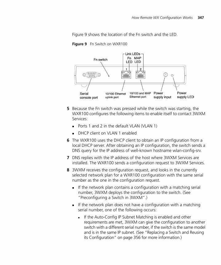
How Remote WX Configuration Works 347
Figure 9 shows the location of the Fn switch and the LED.
Figure 9 Fn Switch on WXR100
5 Because the Fn switch was pressed while the switch was starting, the WXR100 configures the following items to enable itself to contact 3WXM Services:
Ports 1 and 2 in the default VLAN (VLAN 1)
DHCP client on VLAN 1 enabled
6 The WXR100 uses the DHCP client to obtain an IP configuration from a local DHCP server. After obtaining an IP configuration, the switch sends a DNS query for the IP address of well-known hostname wlan-config-srv.
7 DNS replies with the IP address of the host where 3WXM Services are installed. The WXR100 sends a configuration request to 3WXM Services.
8 3WXM receives the configuration request, and looks in the currently selected network plan for a WXR100 configuration with the same serial number as the one in the configuration request.
If the network plan contains a configuration with a matching serial number, 3WXM deploys the configuration to the switch. (See “Preconfiguring a Switch in 3WXM”.)
If the network plan does not have a configuration with a matching serial number, one of the following occurs:
If the Auto-Config IP Subnet Matching is enabled and other requirements are met, 3WXM can give the configuration to another switch with a different serial number, if the switch is the same model and is in the same IP subnet. (See “Replacing a Switch and Reusing its Configuration” on page 356 for more information.)
348 CHAPTER 9: CONFIGURING WX SWITCHES REMOTELY
If the serial number does not match and the Auto-Config IP Subnet Matching option is disabled, 3WXM cannot give the switch a configuration. 3WXM generates a verification warning (on the Network Verification tab). The warning lists the serial number and IP address. The network administrator can upload the switch into the network plan, configure switch parameters, and deploy the configuration to the switch. (See “Uploading a Partially Configured Switch and Completing its Configuration with 3WXM” on page 355.)
Staged WX
1 The switch is shipped to a network administrator who configures IP address and DNS information on the switch, and enables the auto-config option, to configure the switch to contact 3WXM Services in the corporate network.
The network administrator can configure the switch to use a DCHP client to obtain IP information, or can statically configure the information. The IP address and default router (gateway) are required.
DNS information is optional, but is recommended if DNS is available. If DNS is available, an entry must be added to the DNS server that maps the IP address of the host where 3WXM Service are installed to the well-known hostname wlan-config-srv. Otherwise, an IP alias can be configured on the switch itself to map the address to the hostname.
2 The preconfigured switch is shipped to the remote office where it will be deployed.
3 Someone at the remote office physically installs the switch and MAPs.
4 The person at the remote office powers the switch on. The switch boots using the configuration created during staging.
5 The switch either uses its DHCP client to obtain an IP address from a local DHCP server, or uses a statically configured address. This depends on the preconfiguration.
6 If the auto-config option is enabled, the switch sends a DNS query for the IP address of well-known hostname wlan-config-srv.
7 DNS replies with the IP address of the host where 3WXM Services are installed. The switch sends a request to 3WXM Services in the corporate network for a configuration. (If the auto-config option is not enabled, the switch boots using its configuration file. You can use the CLI, 3WXM, or Web Management to complete its configuration.)
3WXM Requirements 349
8 3WXM receives the configuration request, and looks in the currently open network plan for a switch configuration with the same model and serial number as the one in the configuration request.
If the network plan contains a configuration with a matching model and serial number, 3WXM sends the configuration to the switch. (See “Preconfiguring a Switch in 3WXM”.)
If the network plan does not have a configuration with a matching serial number, one of the following occurs:
If the Auto-Config IP Subnet Matching is enabled and other requirements are met, 3WXM can give the configuration to another switch with a different serial number, if the switch is the same model and is in the same IP subnet. (See “Replacing a Switch and Reusing its Configuration” on page 356 for more information.)
If the serial number does not match and the Auto-Config IP Subnet Matching option is disabled, 3WXM cannot give the switch a configuration. 3WXM generates a verification warning (on the Network Verification tab). The warning lists the serial number and IP address. The network administrator can upload the switch into the network plan, configure switch parameters, and deploy the configuration to the switch. (See “Uploading a Partially Configured Switch and Completing its Configuration with 3WXM” on page 355.)
3WXM Requirements
3WXM must be installed and 3WXM Services must be running.
The 3WXM Services option to always accept self-signed certificates must be enabled. This is required if you are using the drop-ship option with a WXR100, or you have staged any model switch with a self-signed certificate. (This option is disabled by default.)
The network plan containing the WX switches must be open.
Preconfiguring the switch in the network plan is optional. If you know the serial number, you can preconfigure the switch in the network plan, and let 3WXM Services deploy the configuration to the switch.
If you do not know the serial number, you still can use 3WXM to configure the switch. However, you will need to wait for the switch to contact 3WXM, so you can upload the configuration, modify the configuration, then deploy the modified configuration back to the switch.
350 CHAPTER 9: CONFIGURING WX SWITCHES REMOTELY
Staging a WX Switch for Configuration by 3WXM
The auto-config option must be enabled on a WX switch in order for the switch to try to contact 3WXM Services for configuration. The auto-config option is automatically enabled on an unconfigured WXR100 when the Fn switch is pressed during power on. However, auto-config is disabled by default on other models.
If you want another WX switch model to be able to access 3WXM Services for a configuration, you must preconfigure the WX with the following information:
IP address
Default router address
Domain name and DNS server address
You can enable the switch to use the MSS DHCP client to obtain this information from a DHCP server in the local network where the switch will be deployed. Alternatively, you can statically configure the information.
The IP address and DNS information are configured independently. You can configure the combination of settings that work with the network resources available at the deployment site. The following examples show some of the combinations you can configure.
If DNS is available, an entry must be added to the DNS server that maps the IP address of the host where 3WXM Services are installed to the well-known hostname wlan-config-srv. Otherwise, an IP alias can be configured on the switch itself to map the address to the hostname.
Example 1:Deployment Site HasDHCP and Local DNS
The deployment site in this example has a DHCP server. The switch is configured to use the MSS DHCP client to obtain an IP address, default router address, DNS domain name, and DNS server IP addresses.
1 Configure a VLAN:
W X1200# set vlan 1 port 7success: change accepted.
2 Enable the DHCP client on VLAN 1:
W X1200# set interface 1 ip dhcp-client enablesuccess: change accepted.
Staging a WX Switch for Configuration by 3WXM 351
3 Enable the auto-config option:
W X1200# set auto-config enablesuccess: change accepted.
4 Save the configuration changes:
W X1200# save configsuccess: configuration saved.
5 Power off or restart the switch.
Example 2:Deployment Site Has
No DHCP and No DNS
The deployment site in this example does not have a DHCP server or a local DNS server. Therefore, IP and DNS information must be statically configured. Because no DNS server is available, an IP alias is configured to map the IP address of the host where 3WXM Services are installed to the well-known hostname wlan-config-srv.
1 Configure a VLAN:
W X1200# set vlan 1 port 7success: change accepted.
2 Configure an IP interface on the VLAN.
W X1200# set interface 1 ip 192.168.1.252 255.255.255.0success: change accepted.
3 Configure a default route through the local default router:
W X1200# set ip route default 192.168.1.1 1success: change accepted.
4 Configure the default DNS domain name:
W X1200# set ip dns domain example.comDomain name changed
5 Configure an IP alias to map the 3WXM server IP address to the well-known name wlan-config-srv:
W X1200# set ip alias wlan-config-srv 172.16.22.846 Enable the auto-config option:
W X1200# set auto-config enablesuccess: change accepted.
7 Save the configuration changes:
W X1200# save configsuccess: configuration saved.
8 Power off or restart the switch.
352 CHAPTER 9: CONFIGURING WX SWITCHES REMOTELY
Example 3:Deployment Site Has
DNS But No DHCP
The deployment site in this example does not have a DHCP server but does have a local DNS server. The configuration is similar to Example 1, but includes DNS configuration information instead of an IP alias.
1 Configure a VLAN:
W X1200# set vlan 1 port 7success: change accepted.
2 Configure an IP interface on the VLAN.
W X1200# set interface 1 ip 192.168.1.252 255.255.255.0success: change accepted.
3 Configure a default route through the local default router:
W X1200# set ip route default 192.168.1.1 0success: change accepted.
4 Configure the default DNS domain name:
W X1200# set ip dns domain example.comDomain name changed
5 Configure DNS server information:
W X1200# set ip dns server 192.168.11.26 Enable the MSS DNS client:
W X1200# set ip dns server enablesuccess: change accepted.
7 Enable the auto-config option:
W X1200# set auto-config enablesuccess: change accepted.
8 Save the configuration changes:
W X1200# save configsuccess: configuration saved.
9 Power off or restart the switch.
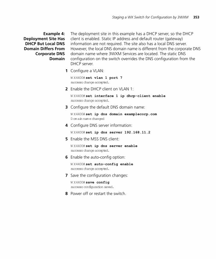
Staging a WX Switch for Configuration by 3WXM 353
Example 4:Deployment Site HasDHCP But Local DNS
Domain Differs FromCorporate DNS
Domain
The deployment site in this example has a DHCP server, so the DHCP client is enabled. Static IP address and default router (gateway) information are not required. The site also has a local DNS server. However, the local DNS domain name is different from the corporate DNS domain name where 3WXM Services are located. The static DNS configuration on the switch overrides the DNS configuration from the DHCP server.
1 Configure a VLAN:
W X4400# set vlan 1 port 7success: change accepted.
2 Enable the DHCP client on VLAN 1:
W X4400# set interface 1 ip dhcp-client enablesuccess: change accepted.
3 Configure the default DNS domain name:
W X4400# set ip dns domain examplecorp.comDomain name changed
4 Configure DNS server information:
W X4400# set ip dns server 192.168.11.25 Enable the MSS DNS client:
W X4400# set ip dns server enablesuccess: change accepted.
6 Enable the auto-config option:
W X4400# set auto-config enablesuccess: change accepted.
7 Save the configuration changes:
W X4400# save configsuccess: configuration saved.
8 Power off or restart the switch.
354 CHAPTER 9: CONFIGURING WX SWITCHES REMOTELY
Preconfiguring a Switch in 3WXM
If you know the serial number, use the following procedure to set up the configuration in 3WXM.
1 Start 3WXM Services.
2 Start a 3WXM Client and connect to 3WXM Services.
3 Select Services > Setup from the menu bar in the main 3WXM window. The 3WXM Services Setup web page appears in your browser.
4 Select Accept self-signed certificates, in the Connection Security area.
5 Click Save.
6 Open the network plan for the site, or select Plan Management and New Plan to create a new network plan.
7 In the main 3WXM window, access the Create Wireless Switch wizard:
a Select the Configuration tool bar option.
b In the Organizer panel, select the network plan name.
c In the Task List panel, select Create Wireless Switch.
8 Enter a name for the switch in the WX Name box.
9 Select the switch model.
10 Enter the serial number in the Serial Number box.
11 Configure other deployment parameters for the switch as required.
You can configure an enable password for the switch even if it does not already have one. When sending the configuration, 3WXM tries the configured password first, then tries a blank password if the enable password does not match the one on the switch. If the switch does not have an enable password, the blank password is accepted. 3WXM then sends the configuration to the switch, including the configured (non-blank) enable password.
12 Click Finish to save the switch configuration and close the wizard.
Leave 3WXM Services running, with the network plan open. When the switch is powered on at the remote site (and the Fn switch is pressed, if a WXR100), the switch contacts 3WXM Services to request a configuration.
Preconfiguring a Switch in 3WXM 355
Uploading a PartiallyConfigured Switchand Completing itsConfiguration with
3WXM
Even if you do not know the serial number of a WX switch, you still can configure the switch in 3WXM. When the switch contacts 3WXM for a configuration, 3WXM generates a warning message such as the following:
No M atching configuration found for serial number – serial-number; IP=ip-addr
You can upload the switch into 3WXM, complete its configuration, then deploy the complete configuration back to the switch.
1 Select the Verification option on the 3WXM tool bar.
2 Click on the warning message.
3 In the Resolutions section, click on Upload WX to display the Upload WX wizard.
4 The IP address is already filled in.
5 Type the Enable password, if one is configured on the switch. If an Enable password has not been configured yet, leave the Enable Password box blank.
6 Click Finish.
3WXM uploads the configuration file from the switch into the network plan. The switch appears in the Equipment section of the Organizer panel.
7 Select the Configuration tab on the 3WXM tool bar.
8 Select the WX switch.
9 Create or modify parameter settings for the switch.
After completing all of the changes, click Save.
10 Select the Verification option on the 3WXM tool bar.
11 Review any error or warning messages for the switch.
12 Click on an error or warning message to display more information, and a list of resolutions for the error or warning condition.
13 Click on a resolution to correct the error or warning condition.
14 Select the Devices option on the 3WXM tool bar.
15 Select the switch.
16 In the Task List panel, select Deploy.
356 CHAPTER 9: CONFIGURING WX SWITCHES REMOTELY
Replacing a Switch and Reusing its Configuration
If a remote switch that is configured by 3WXM fails, you can install a new switch in its place and use 3WXM to configure the switch with the replaced configuration.
This method of switch replacement requires preconfiguration of an auto-config setting by the network administrator, but does not require any configuration by the person who actually performs the replacement at the remote office.
Remote switch replacement is disabled by default but can be enabled on a global basis in the network plan.
This feature applies only when the wireless switch being replaced is the only wireless switch in the network. (Also see the next section, “Requirements”.)
Requirements This method of switch replacement works only under the following conditions:
The new switch must be the same model as the one being replaced.
The new switch must run the same major MSS version (for example, 4.1.x) as the one being replaced.
For models other than the WXR100, the new switch must be pre-staged by a network administrator. (See “Staging a WX Switch for Configuration by 3WXM” on page 350.)
The new switch must send its configuration request to 3WXM from the same IP subnet as the management address of the switch being replaced. 3WXM will give the new switch the same IP address as the old switch.
The new switch must be the only WX switch on the subnet.
How SwitchReplacement Works
1 A network administrator enables the Auto-Config IP Subnet Matching option in 3WXM. (This option is on the 3WXM Services Setup dialog.)
2 Someone at the remote office physically unplugs the failed switch and plugs in a new, unconfigured switch or a pre-staged switch.
3 The person at the remote office powers on the new switch.
Replacing a Switch and Reusing its Configuration 357
If the switch is a WXR100, the person at the remote office also inserts a paperclip or similar object into the Fn hole of the WXR100 to press the Fn switch. Normally, the Fn LED (the right LED above port 1) remains solidly lit for 3 seconds after power on. However, when the Fn switch is pressed, the LED flashes for 3 seconds instead.
4 The new switch requests a configuration from 3WXM, using the process described in “Drop Ship (WXR100 Only)” on page 346 or “Staged WX” on page 348. (The process depends on whether the switch is a WXR100 or is any model that has been prestaged.)
5 3WXM finds a switch configuration that matches the model and MSS version and has a management interface in the same subnet as the new switch.
3WXM also notices that the serial number of the new switch does not match the serial number in the switch configuration in 3WXM. However, because the Auto-Config IP Subnet Matching option is enabled, 3WXM does not reject the configuration request.
EnablingReplacement of
Remote Switches
This configuration task is performed by the network administrator using 3WXM.
To enable replacement of remote switches
1 Open the network plan that contains the remote switches you want to allow to be replaced.
2 Select Services > Setup from the menu bar in the main 3WXM window. The 3WXM Services Setup web page appears in your browser.
3 Select Server Settings in the left column.
4 Select Auto-Config IP Subnet Matching.
5 Click Save at the bottom of the page.
358 CHAPTER 9: CONFIGURING WX SWITCHES REMOTELY
Replacing a Switch This task is performed by someone at the remote office and does not require a network administrator.
3Com recommends that you read through the entire procedure before beginning.
To replace a switch
1 Remove the power cord from the old switch.
2 Unplug the network cables from the old switch.
If the cables are not already labeled to indicate the switch port numbers to which they are connected, you might want to label them before unplugging them.
3 Plug the network cables into the new switch.
4 Plug the power cord into the new switch.
5 Perform this step only if the switch is a WXR100 and was not prestaged by your network administrator.
While the switch is powering on, insert a paperclip or similar object into the Fn hole of the WXR100 to press the Fn switch.
Normally, the Fn LED (the right LED above port 1) remains solidly lit for 3 seconds after power on. However, when the Fn switch is pressed, the LED flashes for 3 seconds instead.

10 MANAGING WX SYSTEM IMAGES AND CONFIGURATIONS
This chapter describes the management of WX system files. It includes information about uploading a WX switch configuration into 3WXM, verifying configuration information, synchronizing local and network changes, deploying WX switches from a network plan to the network, distributing image and configuration files, importing and exporting WX switch configuration files, working with domain policies, and rebooting WX switches or MAP access points.
WX File Management Options
3WXM provides many options for managing WX system image files and configuration files. Table 23 lists the options and the places in this document where the options are described.
Table 23 WX File Management Options in 3WXM
Option Description
Upload configuration
Creates a new WX switch in a network plan, by copying the configuration file from the live switch in the network.
(See “Adding a Switch by Uploading its Configuration from the Network” on page 171.)
Configure and apply policies
Applies configuration settings from policies to a single switch or multiple switches.
(See “Configuring and Applying Policies” on page 387.)
Deploy Sends WX switch configurations from the network plan into the live network, to implement the network plan on the live switches.
(See “Deploying Switch Configuration Changes” on page 366.)
Verify configuration changes
Checks switch configuration changes against a set of configuration rules, alerts you to configuration items that do not fit the rules, and enables you to either edit these configuration items or ignore the rules.
(See “Verifying Configuration Changes” on page 377.)
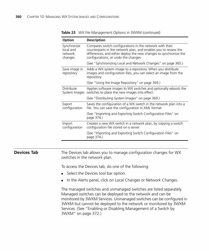
360 CHAPTER 10: MANAGING WX SYSTEM IMAGES AND CONFIGURATIONS
Devices Tab The Devices tab allows you to manage configuration changes for WX switches in the network plan.
To access the Devices tab, do one of the following:
Select the Devices tool bar option.
In the Alerts panel, click on Local Changes or Network Changes.
The managed switches and unmanaged switches are listed separately. Managed switches can be deployed to the network and can be monitored by 3WXM Services. Unmanaged switches can be configured in 3WXM but cannot be deployed to the network or monitored by 3WXM Services. (See “Enabling or Disabling Management of a Switch by 3WXM” on page 372.)
Synchronize local and network changes
Compares switch configurations in the network with their counterparts in the network plan, and enables you to review the differences, and either deploy the new changes to synchronize the configurations, or undo the changes.
(See “Synchronizing Local and Network Changes” on page 365.)
Save image in repository
Adds a WX system image to a repository. When you distribute images and configuration files, you can select an image from the repository.
(See “Using the Image Repository” on page 369.)
Distribute System Images
Applies software images to WX switches and optionally reboots the switches to place the new images into effect.
(See “Distributing System Images” on page 369.)
Export configuration
Saves the configuration of a WX switch in the network plan into a file. You can save the configuration in XML format.
(See “Importing and Exporting Switch Configuration Files” on page 374.)
Import configuration
Creates a new WX switch in a network plan, by copying a switch configuration file stored on a server.
(See “Importing and Exporting Switch Configuration Files” on page 374.)
Table 23 WX File Management Options in 3WXM (continued)
Option Description
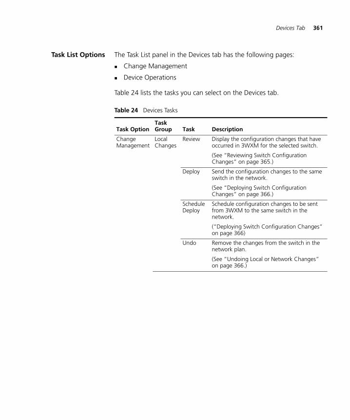
Devices Tab 361
Task List Options The Task List panel in the Devices tab has the following pages:
Change Management
Device Operations
Table 24 lists the tasks you can select on the Devices tab.
Table 24 Devices Tasks
Task OptionTask Group Task Description
Change Management
Local Changes
Review Display the configuration changes that have occurred in 3WXM for the selected switch.
(See “Reviewing Switch Configuration Changes” on page 365.)
Deploy Send the configuration changes to the same switch in the network.
(See “Deploying Switch Configuration Changes” on page 366.)
Schedule Deploy
Schedule configuration changes to be sent from 3WXM to the same switch in the network.
(“Deploying Switch Configuration Changes” on page 366)
Undo Remove the changes from the switch in the network plan.
(See “Undoing Local or Network Changes” on page 366.)
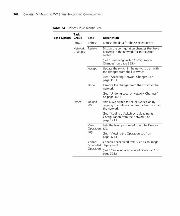
362 CHAPTER 10: MANAGING WX SYSTEM IMAGES AND CONFIGURATIONS
Other Refresh Refresh the data for the selected device.
Network Changes
Review Display the configuration changes that have occurred in the network for the selected switch.
(See “Reviewing Switch Configuration Changes” on page 365.)
Accept Update the switch in the network plan with the changes from the live switch.
(See “Accepting Network Changes” on page 366.)
Undo Remove the changes from the switch in the network.
(See “Undoing Local or Network Changes” on page 366.)
Other Upload WX
Add a WX switch to the network plan by copying its configuration from a live switch in the network.
(See “Adding a Switch by Uploading its Configuration from the Network” on page 171.)
View Operation Log
Lists the tasks performed using the Devices tab.
(See “Viewing the Operation Log” on page 373.)
Cancel Scheduled Operation
Cancels a scheduled task, such as an image deployment.
(See “Canceling a Scheduled Operation” on page 373.)
Table 24 Devices Tasks (continued)
Task OptionTask Group Task Description
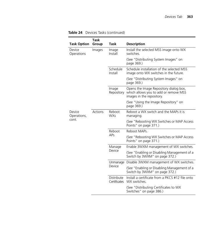
Devices Tab 363
Device Operations
Images Image Install
Install the selected MSS image onto WX switches.
(See “Distributing System Images” on page 369.)
Schedule Install
Schedule installation of the selected MSS image onto WX switches in the future.
(See “Distributing System Images” on page 369.)
Image Repository
Opens the Image Repository dialog box, which allows you to add or remove MSS images in the repository.
(See “Using the Image Repository” on page 369.)
Device Operations, cont.
Actions Reboot WXs
Reboot a WX switch and the MAPs it is managing.
(See “Rebooting WX Switches or MAP Access Points” on page 371.)
Reboot APs
Reboot MAPs.
(See “Rebooting WX Switches or MAP Access Points” on page 371.)
Manage Device
Enable 3WXM management of WX switches.
(See “Enabling or Disabling Management of a Switch by 3WXM” on page 372.)
Unmanage Device
Disable 3WXM management of WX switches.
(See “Enabling or Disabling Management of a Switch by 3WXM” on page 372.)
Distribute Certificates
Install a certificate from a PKCS #12 file onto WX switches.
(See “Distributing Certificates to WX Switches” on page 386.)
Table 24 Devices Tasks (continued)
Task OptionTask Group Task Description
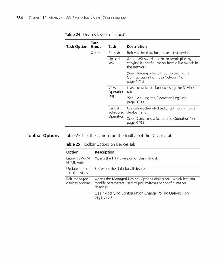
364 CHAPTER 10: MANAGING WX SYSTEM IMAGES AND CONFIGURATIONS
Toolbar Options Table 25 lists the options on the toolbar of the Devices tab.
Other Refresh Refresh the data for the selected device.
Upload WX
Add a WX switch to the network plan by copying its configuration from a live switch in the network.
(See “Adding a Switch by Uploading its Configuration from the Network” on page 171.)
View Operation Log
Lists the tasks performed using the Devices tab.
(See “Viewing the Operation Log” on page 373.)
Cancel Scheduled Operation
Cancels a scheduled task, such as an image deployment.
(See “Canceling a Scheduled Operation” on page 373.)
Table 24 Devices Tasks (continued)
Task OptionTask Group Task Description
Table 25 Toolbar Options on Devices Tab
Option Description
Launch 3WXM HTML Help
Opens the HTML version of this manual.
Update status for all devices
Refreshes the data for all devices.
Edit managed devices options
Opens the Managed Devices Options dialog box, which lets you modify parameters used to poll switches for configuration changes.
(See “Modifying Configuration Change Polling Options” on page 376.)
Synchronizing Local and Network Changes 365
Synchronizing Local and Network Changes
Whenever configuration changes occur to a switch, 3WXM alerts you that changes have occurred. If a configuration change occurs on a switch in the network or in the network plan, so that the network and network plan are out of sync, 3WXM displays a message in a popup window to alert you that a change has occurred.
The Devices tab enables you to review changes and synchronize the switches in the network with their counterparts in 3WXM by either copying the changes to the other switch, or removing the changes from the switch that was changed.
A row of information is displayed for each switch. The Local Status and Network Status columns indicate where changes have occurred.
Reviewing SwitchConfiguration
Changes
To review switch configuration changes:
1 Select the Devices tool bar option.
2 At the bottom of the Task List panel, select Change Management.
3 Select one or more WX switches.
To select multiple switches, press Shift (for contiguous switches) or Control (for noncontiguous switches) while clicking.
4 In the Local Changes or Network Changes group in the Task List panel, select Review.
Selecting Review in Local Changes displays changes made in 3WXM.
Selecting Review in Network Changes displays changes that have occurred in the network.
5 To print the changes, click Print.
6 Click Close to return to the Managed Devices tab.
366 CHAPTER 10: MANAGING WX SYSTEM IMAGES AND CONFIGURATIONS
Accepting NetworkChanges
To accept network changes:
1 Select the Devices tool bar option.
2 At the bottom of the Task List panel, select Change Management.
3 Select one or more WX switches.
To select multiple switches, press Shift (for contiguous switches) or Control (for noncontiguous switches) while clicking.
4 In the Task List panel in the Network Changes group, click Accept.
The status is shown in the Network Status and Local Status columns.
Undoing Local orNetwork Changes
To undo local or network changes:
1 Select the Devices tool bar option.
2 At the bottom of the Task List panel, select Change Management.
3 Select one or more WX switches.
To select multiple switches, press Shift (for contiguous switches) or Control (for noncontiguous switches) while clicking.
4 In the Local Changes or Network Changes group in the Task List panel, select Undo.
Selecting Undo in Local Changes reverses changes made in 3WXM.
Selecting Undo in Network Changes reverses changes that have occurred in the network.
The status is shown in the Network Status and Local Status columns.
Deploying SwitchConfiguration
Changes
You can deploy changes immediately or schedule them to be deployed later.
When you deploy changes to a WX, all of the changes are sent as a single transaction. If any parameter is unsuccessfully changed, the entire transaction is rolled back. If the transaction is successful, the configuration changes are immediately and dynamically put into effect. (A reboot is not required.)
The following procedures provide steps for deploying configuration changes from the Devices tab. You also can immediately deploy changes from the Configuration tab, by clicking Deploy.
Synchronizing Local and Network Changes 367
To immediately deploy local changes
1 Select the Devices tool bar option.
2 At the bottom of the Task List panel, select Change Management.
3 Select one or more WX switches.
To select multiple switches, press Shift (for contiguous switches) or Control (for noncontiguous switches) while clicking.
4 In the Local Changes group in the Task List panel, click Deploy. The Deploy Configurations dialog box appears.
The dialog lists the switches that have configuration changes.
5 Select the switches to which you want to deploy the changes.
To select more than one WX, click Shift while clicking to select contiguous items, or click Ctrl while clicking to select noncontiguous items.
6 Click Deploy.
The deployment status for each affected WX is shown in the History window at the bottom left of the dialog box.
3WXM performs verification of the changes. If errors occur, they are listed in the Selected Errors at the bottom right of the dialog box. If there are errors, fix them and verify the changes before trying to deploy again. (You can use the Verification tab to fix the errors. See “” on page 377.)
If the deploy is successful, 3WXM also instructs the WX switch to save the changes in its configuration file.
7 Click Close.
You can click Close at any time after clicking Deploy. The operation continues in the background. To review the status of the operation, use the operation log. (See “Viewing the Operation Log” on page 373.)
To schedule deployment of local changes
1 Select the Devices tool bar option.
2 At the bottom of the Task List panel, select Change Management.
3 Select one or more WX switches.
To select multiple switches, press Shift (for contiguous switches) or Control (for noncontiguous switches) while clicking.
368 CHAPTER 10: MANAGING WX SYSTEM IMAGES AND CONFIGURATIONS
4 In the Task List panel in the Local Changes group, click Schedule Deploy. The Schedule Deploy dialog box appears.
5 Edit the start date and time.
(The date and time are based on the date and time on the machine where 3WXM Services is installed.)
6 Click OK.
Synchronizing Whenthe Network and
3WXM HaveNonmatching
Changes
If a WX switch in the network has configuration changes and the counterpart in the network plan also has changes but the changes are different, you still can synchronize the changes.
The Devices tab indicates that both the network and the network plan have nonmatching changes in the following ways:
When you select the WX switch, the links in both the Local Changes and Network Changes groups of the Task List panel become active.
When you click Deploy, the deployment is not performed and the following message is displayed instead: wx is not synchronized.
To synchronize the changes, do one of the following:
Review and either deploy (local changes) or accept (network changes), then review and either deploy or accept the other set of changes.
Reject one set of changes (local or network) and accept or deploy the other set of changes.
Reject both sets of changes.
Distributing System Images 369
Distributing System Images
You can use 3WXM to upgrade or downgrade the system image (MSS software) on WX switches. System images include switch software and MAP software.
Using the ImageRepository
Use the image repository to add or delete WX system images. The image file is checked and its version is verified when added to the image repository. Images are stored in the 3Com_installation_directory\images\dp directory.
To add a system image
1 Select the Devices tool bar option.
2 At the bottom of the Task List panel, select Device Operations.
3 In the Task List panel, select Image Repository.
4 Click Add Image. The Add to Repository dialog box appears.
5 Navigate to the directory containing the system image.
6 Select the system image.
7 Click Add to Repository. The image is added to the image repository and appears in the Image List.
8 To close the Image Repository dialog box, click Close.
To delete a system image
1 In the Image Repository dialog box, select the image you want to delete.
2 Click Remove Image. A prompt appears.
3 Click Yes to delete the system image.
4 To close the Image Repository dialog box, click Close.
Distributing SystemImages
You can distribute a system image to one or more WX switches in a network plan.
To use a new system image, you must reboot the WX. For more information, see “Rebooting WX Switches or MAP Access Points” on page 371.
3Com recommends that you use the Verification tab to resolve any configuration errors or warnings before you distribute system images.
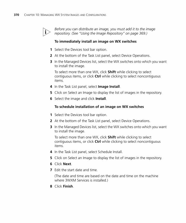
370 CHAPTER 10: MANAGING WX SYSTEM IMAGES AND CONFIGURATIONS
Before you can distribute an image, you must add it to the image repository. (See “Using the Image Repository” on page 369.)
To immediately install an image on WX switches
1 Select the Devices tool bar option.
2 At the bottom of the Task List panel, select Device Operations.
3 In the Managed Devices list, select the WX switches onto which you want to install the image.
To select more than one WX, click Shift while clicking to select contiguous items, or click Ctrl while clicking to select noncontiguous items.
4 In the Task List panel, select Image Install.
5 Click on Select an Image to display the list of images in the repository.
6 Select the image and click Install.
To schedule installation of an image on WX switches
1 Select the Devices tool bar option.
2 At the bottom of the Task List panel, select Device Operations.
3 In the Managed Devices list, select the WX switches onto which you want to install the image.
To select more than one WX, click Shift while clicking to select contiguous items, or click Ctrl while clicking to select noncontiguous items.
4 In the Task List panel, select Schedule Install.
5 Click on Select an Image to display the list of images in the repository.
6 Click Next.
7 Edit the start date and time.
(The date and time are based on the date and time on the machine where 3WXM Services is installed.)
8 Click Finish.
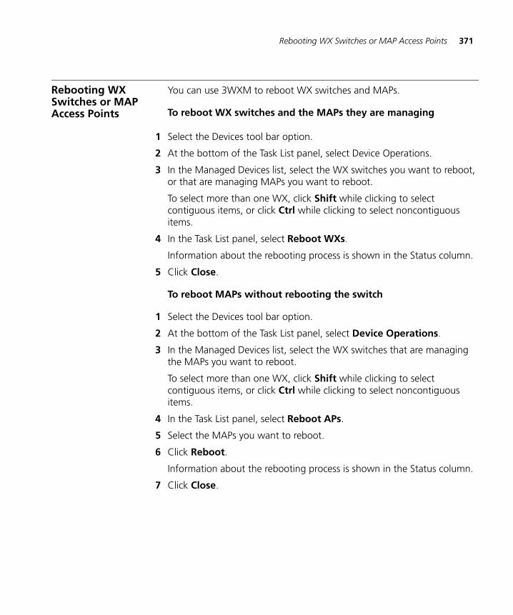
Rebooting WX Switches or MAP Access Points 371
Rebooting WX Switches or MAP Access Points
You can use 3WXM to reboot WX switches and MAPs.
To reboot WX switches and the MAPs they are managing
1 Select the Devices tool bar option.
2 At the bottom of the Task List panel, select Device Operations.
3 In the Managed Devices list, select the WX switches you want to reboot, or that are managing MAPs you want to reboot.
To select more than one WX, click Shift while clicking to select contiguous items, or click Ctrl while clicking to select noncontiguous items.
4 In the Task List panel, select Reboot WXs.
Information about the rebooting process is shown in the Status column.
5 Click Close.
To reboot MAPs without rebooting the switch
1 Select the Devices tool bar option.
2 At the bottom of the Task List panel, select Device Operations.
3 In the Managed Devices list, select the WX switches that are managing the MAPs you want to reboot.
To select more than one WX, click Shift while clicking to select contiguous items, or click Ctrl while clicking to select noncontiguous items.
4 In the Task List panel, select Reboot APs.
5 Select the MAPs you want to reboot.
6 Click Reboot.
Information about the rebooting process is shown in the Status column.
7 Click Close.
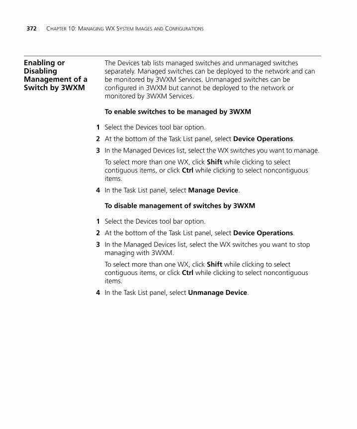
372 CHAPTER 10: MANAGING WX SYSTEM IMAGES AND CONFIGURATIONS
Enabling or Disabling Management of a Switch by 3WXM
The Devices tab lists managed switches and unmanaged switches separately. Managed switches can be deployed to the network and can be monitored by 3WXM Services. Unmanaged switches can be configured in 3WXM but cannot be deployed to the network or monitored by 3WXM Services.
To enable switches to be managed by 3WXM
1 Select the Devices tool bar option.
2 At the bottom of the Task List panel, select Device Operations.
3 In the Managed Devices list, select the WX switches you want to manage.
To select more than one WX, click Shift while clicking to select contiguous items, or click Ctrl while clicking to select noncontiguous items.
4 In the Task List panel, select Manage Device.
To disable management of switches by 3WXM
1 Select the Devices tool bar option.
2 At the bottom of the Task List panel, select Device Operations.
3 In the Managed Devices list, select the WX switches you want to stop managing with 3WXM.
To select more than one WX, click Shift while clicking to select contiguous items, or click Ctrl while clicking to select noncontiguous items.
4 In the Task List panel, select Unmanage Device.
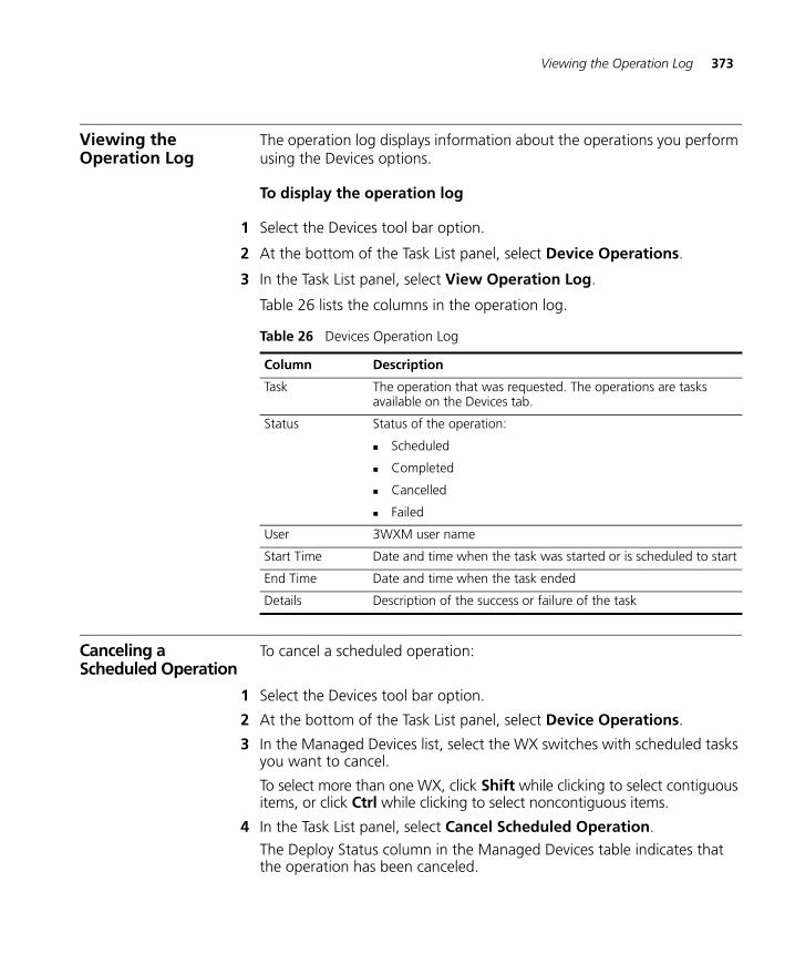
Viewing the Operation Log 373
Viewing the Operation Log
The operation log displays information about the operations you perform using the Devices options.
To display the operation log
1 Select the Devices tool bar option.
2 At the bottom of the Task List panel, select Device Operations.
3 In the Task List panel, select View Operation Log.
Table 26 lists the columns in the operation log.
Canceling a Scheduled Operation
To cancel a scheduled operation:
1 Select the Devices tool bar option.
2 At the bottom of the Task List panel, select Device Operations.
3 In the Managed Devices list, select the WX switches with scheduled tasks you want to cancel.
To select more than one WX, click Shift while clicking to select contiguous items, or click Ctrl while clicking to select noncontiguous items.
4 In the Task List panel, select Cancel Scheduled Operation.
The Deploy Status column in the Managed Devices table indicates that the operation has been canceled.
Table 26 Devices Operation Log
Column Description
Task The operation that was requested. The operations are tasks available on the Devices tab.
Status Status of the operation:
Scheduled
Completed
Cancelled
Failed
User 3WXM user name
Start Time Date and time when the task was started or is scheduled to start
End Time Date and time when the task ended
Details Description of the success or failure of the task
374 CHAPTER 10: MANAGING WX SYSTEM IMAGES AND CONFIGURATIONS
Importing and Exporting Switch Configuration Files
You can import or export switch configuration files in Extensible Markup Language (XML) format.
The import option enables you to create a WX switch in the network plan by importing configuration files in Extensible Markup Language (XML) format. You also can update the configuration of a switch that is already in the plan.
The export option enables you to save a configuration to an XML file. After exporting a WX configuration to an XML file, you can import it to another instance of 3WXM or use it as a backup copy.
If you import a configuration containing information that an older version of 3WXM or MSS does not support, the information is ignored when the configuration is imported.
If you import a switch configuration, you must enable 3WXM management of the switch before you can deploy the switch to the network. (To enable 3WXM management of a switch, see “Modifying Basic Switch Parameters” on page 179.)
To import a configuration
1 In the main 3WXM window, select Tools > Import. The Import Configurations dialog box appears.
2 In the Import Into Mobility Domain group box, select one of the following options:
Click Use File Info to import the configuration information using the Mobility Domain specified in the configuration file.
Click Select to specify a Mobility Domain to import configuration information to. Then select the Mobility Domain from the list.
3 To replace existing WX switch information in 3WXM with information from the configuration file, select Update existing WXs.
4 Click Select Files. The Select Files To Import dialog box appears.
5 Select one or more configuration files to be imported. To make multiple selections, press Shift (for contiguous items) or Control (for noncontiguous items) while clicking items.
6 Click Select Files To Import. The file or files you selected appear in the File Import Results list.
To remove all of the files you previously selected, click Clear Files.
Importing and Exporting Switch Configuration Files 375
7 Click Import. The status of the import process appears in the Status column.
8 Click Close to save the changes.
9 Enable 3WXM to manage the switch. (See “Modifying Basic Switch Parameters” on page 179.)
To export a configuration
1 Select Tools > Export. The Export Configurations dialog box appears.
2 In the Export From list, select the Mobility Domain whose configuration you want to export.
3 If you want to export the configuration file to a different directory, click the Choose button, which is labeled with the current output directory. The Select dialog box appears. Navigate to the directory you want to use as the output directory, and click Select.
4 To overwrite previously exported configuration files, select Overwrite Existing Files.
If you do not select this option, you cannot export a configuration file with the same name as an existing file in the output directory. You can rename the existing file or move the file to another directory.
5 To have 3WXM create a backup copy of a previous configuration file, select Copy Files Before Overwriting.
6 For each WX whose configuration you want to export, make sure the Export checkbox is selected.
7 Click Export to begin the exporting process. Messages appear in the Status column in the WX List box and the Results box.
The configuration is saved in the directory that you specified.
8 To close the Export Configurations dialog box, click Close.
376 CHAPTER 10: MANAGING WX SYSTEM IMAGES AND CONFIGURATIONS
Modifying Configuration Change Polling Options
By default, 3WXM Client polls WX switches in the network every 15 minutes for network changes, and displays a popup message if changes are detected. The popup message is in addition to notification in the Alerts panel.
To modify configuration polling options
1 Select the Devices tool bar option.
2 Click Edit managed devices options on the toolbar of the Device tab. The Managed Device Options dialog box appears.
3 To enable the detection of configuration changes in the network, make sure Enabled is selected next to Poll for configuration changes.
4 To specify how often network checks occur, specify the interval between checks, from 1 to 1440 minutes (24 hours), in the Interval box. The default is 15 minutes.
5 To be notified of network changes by a popup message, select Prompt when network changes are detected.
To disable the popup message, deselect the option.
Disabling the popup message does not affect the Network Changes information in the Alerts panel. The Alerts panel still notifies you of network changes.
6 To instruct WX switches to save deployed configuration changes in their configuration files, select Save WX Configuration on Deploy.
7 Click Close.
11 VERIFYING CONFIGURATION CHANGES
3WXM uses a set of rules to verify WX switch configurations. Changes to a switch’s configuration in 3WXM or in the live network are automatically evaluated by comparing the changes to the rules. If the evaluation detects any error or warning conditions, the information in the Alerts panel is updated:
Errors or warnings in a switch’s configuration in 3WXM affect the Configuration counts.
Errors or warnings in the network affect the Network counts.
Verification Tabs Click on Configuration or Network in the Alerts panel to display the Verification tabs in the Content panel.
The upper section of the panel lists error descriptions in red and lists warning descriptions in orange:
Errors are serious problems that must be addressed before deployment. By default, you cannot deploy a network plan with errors in it. After fixing errors, verify the network plan again to ensure that the errors have been resolved.
Warnings are noncritical issues that do not stop deployment. Review any warnings and consider resolving the issues before deployment.
Details about the selected error or warning appear in the lower left section of the tab.
The Resolution section lists options for resolving the warning or error.
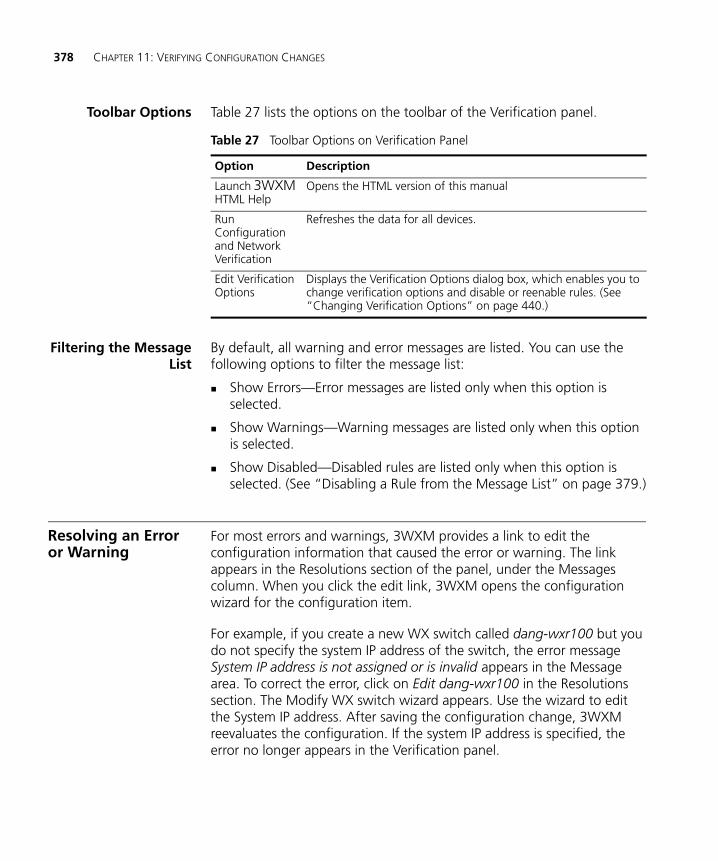
378 CHAPTER 11: VERIFYING CONFIGURATION CHANGES
Toolbar Options Table 27 lists the options on the toolbar of the Verification panel.
Filtering the MessageList
By default, all warning and error messages are listed. You can use the following options to filter the message list:
Show Errors—Error messages are listed only when this option is selected.
Show Warnings—Warning messages are listed only when this option is selected.
Show Disabled—Disabled rules are listed only when this option is selected. (See “Disabling a Rule from the Message List” on page 379.)
Resolving an Error or Warning
For most errors and warnings, 3WXM provides a link to edit the configuration information that caused the error or warning. The link appears in the Resolutions section of the panel, under the Messages column. When you click the edit link, 3WXM opens the configuration wizard for the configuration item.
For example, if you create a new WX switch called dang-wxr100 but you do not specify the system IP address of the switch, the error message System IP address is not assigned or is invalid appears in the Message area. To correct the error, click on Edit dang-wxr100 in the Resolutions section. The Modify WX switch wizard appears. Use the wizard to edit the System IP address. After saving the configuration change, 3WXM reevaluates the configuration. If the system IP address is specified, the error no longer appears in the Verification panel.
Table 27 Toolbar Options on Verification Panel
Option Description
Launch 3WXM HTML Help
Opens the HTML version of this manual
Run Configuration and Network Verification
Refreshes the data for all devices.
Edit Verification Options
Displays the Verification Options dialog box, which enables you to change verification options and disable or reenable rules. (See “Changing Verification Options” on page 440.)
Resolving an Error or Warning 379
To resolve an error or warning
1 Select the error or warning message in the Message column.
2 Read the information in the Error/Warning Details section. For some errors and warnings, this section contains information about how to resolve the error or warning.
3 If an option is listed in the Resolution section, click on the option to display the configuration wizard for the item.
4 Edit the configuration item or resolve the network issue and save the change.
5 Refresh the information in the Verification panel.
6 Check the messages to see whether the error or warning is gone.
Disabling a Rule fromthe Message List
All 3WXM rules are enabled by default. If you want 3WXM to stop alerting you about a specific error or warning, you can disable the rule for that error or warning.
You can disable rules on a per-instance basis or globally for all instances.
If you disable a rule for a specific instance, 3WXM stops alerting you about that particular instance but still uses the rule when evaluating other configuration items.
If you disable a rule for all instances, 3WXM stops using that rule altogether when verifying a configuration.
Rules that are disabled for all instances are disabled on a per-user basis, not a per-plan basis. When you disable all instances of a rule, the rule is disabled for any network plan that you open while you are logged on with the 3WXM Client user name you were logged on with when you disabled the rule.
To disable a specific instance of a warning or error
1 Select the warning or error message.
2 In the Resolutions section, click disable this rule for this instance only.
As soon as you click on this option, the message disappears from the list. 3WXM will not display this particular instance of the message again.
380 CHAPTER 11: VERIFYING CONFIGURATION CHANGES
To globally disable a warning or error
1 Select an instance of the warning or error message.
2 In the Resolutions section, click disable this rule for all instances.
As soon as you click on this option, all instances of the message disappear from the list. 3WXM will not display the message again.
Changing VerificationOptions
By default, 3WXM verifies configuration information in the following cases:
When the configuration is changed in 3WXM.
When you deploy or export a switch from 3WXM to the network.
When you upload a switch from the network into 3WXM.
3WXM verifies the entire switch configuration by default each time a change occurs.
In addition, 3WXM allows you to deploy or export configuration changes that cause error messages by default.
To change verification options
1 On the toolbar of the Verification panel click the Edit Verification Options icon. The Verification Options dialog box appears.
2 Select the cases in which you want 3WXM to perform verification:
Verify changes only—3WXM performs verification only on configuration items that change, instead of verifying the entire configuration when any change in that configuration occurs.
Verify on edits—3WXM performs verification whenever you edit a configuration.
Verify on deploy and export—3WXM performs verification when you select the option to deploy switches from 3WXM to the live network.
Verify on upload—3WXM performs verification when you select the option to upload a switch’s configuration from the network into 3WXM.
Allow errors to be deployed and exported—3WXM allows you to deploy or export a configuration even if it contains errors.
Resolving an Error or Warning 381
3Com recommends that you do not deploy a network plan that contains configuration errors. Allowing configuration errors to be deployed to the network can affect network stability.
3 Click Close to place the changes into effect and close the dialog box.
Disabling andReenabling Rules
If you disable a rule, you can use the Verification Options dialog box to reenable the rule. You also can disable rules, for the entire network plan or for specific instances.
To disable or reenable a rule:
1 On the toolbar of the Verification panel click the Edit Verification Options icon. The Verification Options dialog box appears.
2 Click Rules Control. The list of 3WXM verification rules appears.
3 Locate the rule you want to disable. You can click on the Class or Rule headers to sort alphabetically by rule class or by rule name. You also can filter the display to show only the rules in a specific class.
To filter the rule list based on class:
a Click Filter By Class. The rule list changes to list the rules in the selected class.
b Select a rule class from the listbox. The list of rules changes to list the rules in the selected class. In this example, the selected rule class is 802.1X Network Access.
4 In the Enabled column, click on the checkbox next to the rule.
If you are reenabling a rule, go to step 5.
If you are disabling a rule, go to step 8.
5 In the Rule column, click on the rule name. The disable settings are displayed and become editable.
If the rule is disabled for all instances, the Disable All Instances option is selected.
If individual instances of the rule are disabled, the Disable Selected Instances option is selected and the instances are listed. Instances that are disabled have checkmarks in the checkboxes next to them.
382 CHAPTER 11: VERIFYING CONFIGURATION CHANGES
6 Reenable the rule or instances:
To reenable a rule all of whose instances are disabled, click on the checkbox in the Enabled column. The Disable All Instances option is deselected.
To reenable an individual instance of a rule, click on the checkbox next to the instance. Repeat for each instance you want to reenable. Alternatively, if you want to reenable all of the disabled instances, click on the checkbox in the Enabled column.
7 Go to step 10.
8 Click on the checkbox in the Enabled column. The disable options become editable. By default, the Disable All Instances option is selected.
9 To leave all instances disabled, go to step 10.
To disable only specific instances:
a Select Disable Selected Instances. The individual instances of the rule are listed.
b Click next to the instances you want to disable, then go to step 10.
10 Click Close.
12 MANAGING CERTIFICATES
A digital certificate is a form of electronic identification for computers. This chapter describes processing and managing certificates, and distributing PKS #12 files.
Overview A digital certificate is a form of electronic identification for computers. The 3Com Mobility System supports the following types of X.509 digital certificates:
Administrative certificate for the monitoring service or a WX switch
802.1X-EAP certificate for a WX switch
WX-WX security certificate, used by WX switches in a Mobility Domain to securely exchange management information
WebAAA certificate for a WX switch
Certificate authority certificate to validate the administrator’s certificate
Certificate authority certificate to validate user and the EAP server certificates
When 3WXM connects to 3WXM Services or a WX switch, the administrative certificate is used to authenticate the service or WX switch and establish a secure connection.
If a WX switch does not already have certificates, MSS automatically generates them the first time you boot using MSS Version 4.2 or later. You do not need to install certificates unless you want to replace the ones automatically generated by MSS. (For more information, see the “Certificates Automatically Generated by MSS” section in the “Managing Keys and Certificates” chapter of the Wireless LAN Switch and Controller Configuration Guide.)
This does not apply to WX-WX security (domain) certificates. An WX-WX security certificate is generated only when you enable WX-WX security.
384 CHAPTER 12: MANAGING CERTIFICATES
Before installing a new certificate, verify that the WX switch is set to the correct date, time, and time zone. Otherwise, certificates might not be installed correctly.
For more information about certificates on the WX, see the Wireless LAN Switch and Controller Configuration Guide.
Processing Certificates
When 3WXM Client connects to 3WXM Services or to a WX switch that presents a certificate that is unknown to 3WXM Client, the Certificate Check dialog box appears. The dialog shows information about the certificate and allows you to accept or reject the certificate and therefore accept or reject the connection.
Before 3WXM can communicate with the WX switch or 3WXM Services over a secure HTTPS connection, you must specify how to deal with the certificate required for secure communication
The options you select in this dialog box apply to all HTTPS connections with the 3WXM Client. For example, the 3WXM Client also checks the validity of certificates presented by 3WXM Services, and the settings you select in this dialog affect those connections too.
To process a certificate
1 If you do not want to see the Certificate Check dialog box each time 3WXM connects to a WX switch, select one of the following options:
Always accept self-signed certificates. — Use this option to configure the 3WXM Client to always accept a self-signed certificate from the 3WXM monitoring service and from WX switches.
Install this certificate to validate future connections. — Use this option to accept the certificate and consider the certificate to be valid for future connections.
When you use this option, the Certificate Check dialog box is not shown again for the certificate, even if the certificate becomes out of date.
Managing Certificates 385
2 Do one of the following:
Click Accept to allow the connection to the WX switch.
If you did not select either of the options in step 1, when you click Accept, a secure connection with these certificate credentials is allowed for this session until you close the network plan.
Click Reject to reject the connection to the WX switch.
Managing Certificates
After installing certificates, you can review or delete a certificate in the 3WXM certificate store.
Reviewing CertificateDetails
After installing a certificate in 3WXM, you can see information such as the time frame for which the certificate is valid and who issued the certificate.
To review certificate details
1 Select Tools > Certificates from the menu bar in the main 3WXM window.
2 Select a certificate from the list, and click Details. (You can also double-click the certificate to see its details.)
The Certificate Details dialog box appears, listing the certificate information.
3 Click Close.
4 In the Certificate Management dialog box, click Close.
Deleting Certificates To delete certificates, follow these steps.
1 Select Tools > Certificates from the menu bar in the main 3WXM window.
2 Select a certificate from the list.
3 Click Delete.
4 When prompted, click Yes to confirm the certificate deletion, or click No to cancel the deletion.
If you clicked Yes, the certificate is deleted.
5 In the Certificate Management dialog box, click Close.
386 CHAPTER 12: MANAGING CERTIFICATES
Distributing Certificates to WX Switches
You can use 3WXM to distribute certificates from PKCS #12 files to one or more WX switches.
Although you can distribute one PKCS #12 file to many WX switches, as a best practice, you should install a unique certificate and key pair per WX.
1 Select the Devices tool bar option.
2 At the bottom of the Task List panel, select Device Operations.
3 In the Managed Devices list, select the WX switches to which you want to distribute the certificate.
To select more than one WX, click Shift while clicking to select contiguous items, or click Ctrl while clicking to select noncontiguous items.
4 In the Task List panel, select Distribute Certificates.
5 Click Select PKCS12 File.
6 Navigate to the PKCS #12 file and click Select PKCS12 File.
7 In the PKCS12 Password box, type the one-time password used to authenticate the PKCS12 file. The following characters cannot be used as part of the one-time password of a PKCS #12 file: quotation marks (“ ”), question mark (?), ampersand (&).
This password must match the password used when the file was generated.
8 In the Certificate Type list, select one of the following:
EAP — To install an 802.1X/EAP certificate
Web — To install a WebAAA certificate
Admin — To install an administrative certificate
9 Click Start Download. Download progress appears in the Status column.
When the download process is complete, you see a message indicating that the certificate was installed.
13 CONFIGURING AND APPLYING POLICIES
A policy is a set of WX configuration parameters that you can define once in 3WXM and then apply to multiple WX switches. When you apply a policy to a set of WX switches, all parameter settings in the policy are applied to the switches and update the settings already on the switches.
How Changes Are Managed
When you create a new policy, none of the settings for the policy are applied to WX switches (even the ones you associate with the policy when you create it), until you explicitly apply the policy to the switches.
After associating a new policy with a switch, all new switches that match the WX model and version number of the policy automatically receive the parameter settings in the policy. New switches are switches created using the WX Switch wizard or any uploaded switches. However, policy changes are not automatically applied to switches. Reapply the changed policy to associated switches after making any changes to the policy.
Viewing Policies To view policies:
1 Select the Policies tool bar option.
2 To view the feature areas in the policy, click on the plus sign next to the policy name.
Only the areas that are configured in the policy are listed.
Click on the plus sign next to individual feature areas.
3 To view the parameter settings in a feature area, select the feature area.
The settings appear in the Content panel.
388 CHAPTER 13: CONFIGURING AND APPLYING POLICIES
Creating a Policy To create a policy:
1 Access the Create Policy wizard.
a Select the Policies tool bar option.
b In the Task List panel, select Policy.
2 In the Policy Name box, type a name for the policy. This name will appear in the Organizer panel when the Policies tool bar option is selected.
3 To configure a policy for a specific switch model, select the model from the WX Model Filter drop-down list.
4 To configure the policy to support an older version of 3WXM than is currently running, select the version from the WX Version Filter drop-down list.
5 Click Next.
6 Select the feature areas you want to set in the policy.
When you apply the policy to a switch, all parameter settings from all of the selected feature areas are applied to the switch. This includes any settings left at their default settings in the policy.
7 Click Next.
8 In Available Devices list, select the switches to which you want to apply the policy, then click Add to move the switches to the Current Devices list.
Moving a switch to the Current Devices list does not automatically apply the policy to the switch. To apply policy settings, see “Applying Policy Changes to Switches” on page 389.
9 Click Finish and go to “Configuring Feature Settings in a Policy”.
Configuring Feature Settings in a Policy 389
Configuring Feature Settings in a Policy
To configure feature settings in a policy:
1 If you have not already done so, use the procedure in “Creating a Policy” on page 388 to configure a policy and select the switches to which you want to apply the policy.
2 In the Organizer panel, select a feature area.
3 Use the Content panel or wizards accessed from the Task List panel to configure settings for the feature category.
To find information about a feature category, see Table 28 on page 390.
4 Click Save to save the changes to the policy.
5 In the Task List panel, select View to display the switches to which the policy change will apply.
6 Only the settings you change from their default values are listed.
7 After reviewing the changes, click Close.
8 Correct any changes if needed, then go to “Applying Policy Changes to Switches”.
Applying Policy Changes to Switches
To apply policy changes to WX switches:
1 Select Apply in the Task List panel to apply the changes to WX switches that are already associated with the policy.
2 Review the list of switches, then click Apply to apply the changes to the switches.
The changes are automatically applied to switches you associate with the policy after making the changes.
3 After the done message appears in the Apply Policy wizard, click Close.
4 Repeat step 2 through step 3 for each feature category.
Table 28 on page 390 lists the section where you can find configuration information for a feature category.
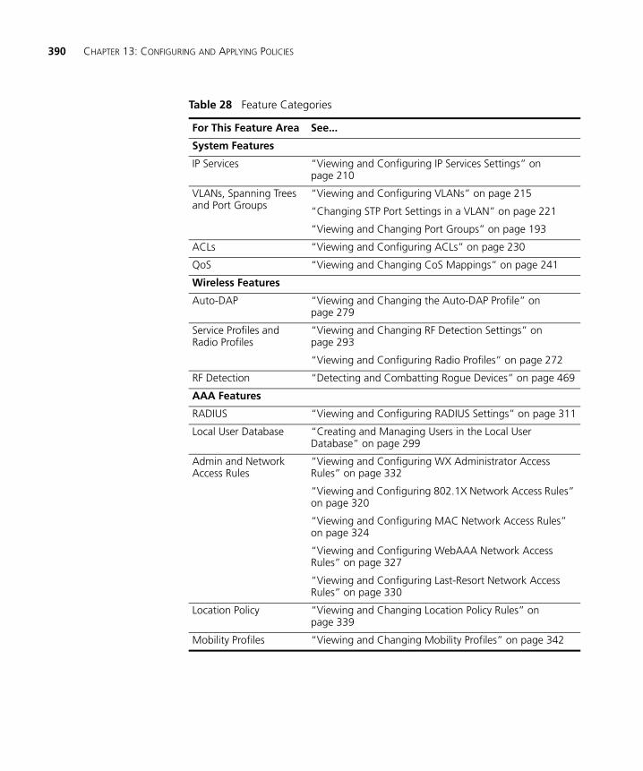
390 CHAPTER 13: CONFIGURING AND APPLYING POLICIES
Table 28 Feature Categories
For This Feature Area See...
System Features
IP Services “Viewing and Configuring IP Services Settings” on page 210
VLANs, Spanning Trees and Port Groups
“Viewing and Configuring VLANs” on page 215
“Changing STP Port Settings in a VLAN” on page 221
“Viewing and Changing Port Groups” on page 193
ACLs “Viewing and Configuring ACLs” on page 230
QoS “Viewing and Changing CoS Mappings” on page 241
Wireless Features
Auto-DAP “Viewing and Changing the Auto-DAP Profile” on page 279
Service Profiles and Radio Profiles
“Viewing and Changing RF Detection Settings” on page 293
“Viewing and Configuring Radio Profiles” on page 272
RF Detection “Detecting and Combatting Rogue Devices” on page 469
AAA Features
RADIUS “Viewing and Configuring RADIUS Settings” on page 311
Local User Database “Creating and Managing Users in the Local User Database” on page 299
Admin and Network Access Rules
“Viewing and Configuring WX Administrator Access Rules” on page 332
“Viewing and Configuring 802.1X Network Access Rules” on page 320
“Viewing and Configuring MAC Network Access Rules” on page 324
“Viewing and Configuring WebAAA Network Access Rules” on page 327
“Viewing and Configuring Last-Resort Network Access Rules” on page 330
Location Policy “Viewing and Changing Location Policy Rules” on page 339
Mobility Profiles “Viewing and Changing Mobility Profiles” on page 342
14 MANAGING ALARMS
A fault or alarm (these two terms are used interchangeably) is generated by a trap, a rule, a status, or a threshold-exceeded event. 3WXM includes a feature to make it easier to manage faults (alarms) that occur in the system.
The Fault Management System also monitors certain traps for third-party applications, and offers administrators the ability to add new trap support when necessary. The type of trap and IP source determine how new trap support should correlate with existing trap support
Setting Up the Fault Management System
Various types of users have different roles in setting up the Fault Management system. These user types include users, service administrators, provisioning users, and monitoring users. These users can perform the following tasks:
Customize faults; for example assign severity to faults and set up e-mail notifications.
Perform fault forwarding using e-mail.
Select the fault based on its category and severity (see “Classifying and Organizing Alarms” on page 393).
Enable or disable faults based on their category or severity (see “Classifying and Organizing Alarms” on page 393).
Modify fault settings in the Fault Management System, service administrators only.
Manage the faults and invoke resolutions, if available, provisioning users.
View faults and acknowledge or unacknowledge the faults, monitoring users.
392 CHAPTER 14: MANAGING ALARMS
Perform the following steps to set up the Fault Management system:
1 Click Setup in the options located on the right side of the Fault Management panel.
2 Select the type of alarms you want to enable by clicking the appropriate check box. Notice that there are several types available for various severity levels.
3 Click the Notification tab and select the severity levels for which 3WXM should send an email notification. You can select severity levels for the following categories:
Performance
Security
Client
System
See “Classifying and Organizing Alarms” on page 393 for more information about the categories.
Enter the appropriate email address in the Email Address field at the bottom of the screen.
4 Click the Database Maintenance tab. The Database Maintenance tab allows you to specify how many faults to store in the database and the number of days to keep uncleared faults. In addition, use this tab to specify the number of days to keep active Critical, Major, Minor, and Informational alarms in the database. Enter the desired values in the following fields:
Number of events per alarm—The number of recent events that should be retained in the database for each alarm.
3WXM allows up to four more events than specified. When a fifth extra event enters the log, 3WXM then prunes the 5 oldest events. For example, if the maximum number of events per alarm is 25, 3WXM does not prune any until the number of events reaches 30. 3WXM then prunes away the 5 oldest events to leave 25 events.
Number of days—The number of days after which any cleared alarms will be deleted from the database.
Critical—The number of days after which any active critical alarms will be removed.
Major—The number of days after which any active major will be aged.
Classifying and Organizing Alarms 393
Minor—The number of days after which any active minor will be aged.
Informational—The number of days after which any active informational will be aged.
5 Click Save.
Classifying and Organizing Alarms
When a fault occurs in 3WXM, the Fault Management System offers a means to categorize the fault by functional area and severity.
3WXM categorizes the fault according to the functional area. Depending on the functional area in which a fault occurs, you can assign the fault to one of the following categories:
System
Performance
Security
Client
3WXM also organizes faults according to severity:
Critical (Red)
Major (Orange)
Minor (Yellow)
Informational (Blue)
3WXM displays a single fault management table that allows you to view all fault-related information, including the fault's functional area and severity, a description of the fault, the source of the fault WX, its current state, and tasks –including alarm management, resolutions, and reports.
For each fault event, 3WXM provides additional information such as the cause, fault object, and event history. The overall status, which is a consolidation of the operational status and fault severity, displays at the appropriate physical or logical entity in the monitoring view.
Click on a fault event, and an information pane will appear at the bottom of the Alarms panel. 3WXM displays the Alarm Details view by default, as shown in the screen below. The Alarm Details view provides additional information regarding a specific fault that does not appear in the tabular form, such as State, Time Created, Last Updated By, Generated By, Transmitter MAC Address, SSID, and Number of Events.
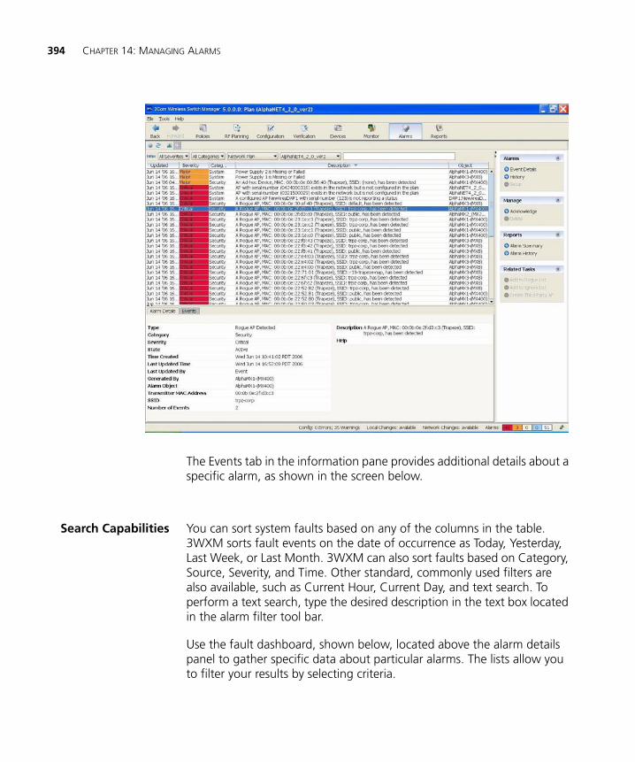
394 CHAPTER 14: MANAGING ALARMS
The Events tab in the information pane provides additional details about a specific alarm, as shown in the screen below.
Search Capabilities You can sort system faults based on any of the columns in the table. 3WXM sorts fault events on the date of occurrence as Today, Yesterday, Last Week, or Last Month. 3WXM can also sort faults based on Category, Source, Severity, and Time. Other standard, commonly used filters are also available, such as Current Hour, Current Day, and text search. To perform a text search, type the desired description in the text box located in the alarm filter tool bar.
Use the fault dashboard, shown below, located above the alarm details panel to gather specific data about particular alarms. The lists allow you to filter your results by selecting criteria.
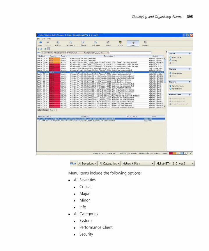
Classifying and Organizing Alarms 395
Menu items include the following options:
All Severities
Critical
Major
Minor
Info
All Categories
System
Performance Client
Security
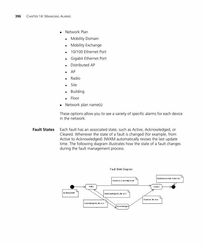
396 CHAPTER 14: MANAGING ALARMS
Network Plan
Mobility Domain
Mobility Exchange
10/100 Ethernet Port
Gigabit Ethernet Port
Distributed AP
AP
Radio
Site
Building
Floor
Network plan name(s)
These options allow you to see a variety of specific alarms for each device in the network.
Fault States Each fault has an associated state, such as Active, Acknowledged, or Cleared. Whenever the state of a fault is changed (for example, from Active to Acknowledged) 3WXM automatically revises the last update time. The following diagram illustrates how the state of a fault changes during the fault management process.
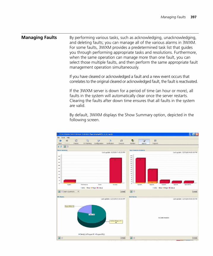
Managing Faults 397
Managing Faults By performing various tasks, such as acknowledging, unacknowledging, and deleting faults; you can manage all of the various alarms in 3WXM. For some faults, 3WXM provides a predetermined task list that guides you through performing appropriate tasks and resolutions. Furthermore, when the same operation can manage more than one fault, you can select those multiple faults, and then perform the same appropriate fault management operation simultaneously.
If you have cleared or acknowledged a fault and a new event occurs that correlates to the original cleared or acknowledged fault, the fault is reactivated.
If the 3WXM server is down for a period of time (an hour or more), all faults in the system will automatically clear once the server restarts. Clearing the faults after down time ensures that all faults in the system are valid.
By default, 3WXM displays the Show Summary option, depicted in the following screen.
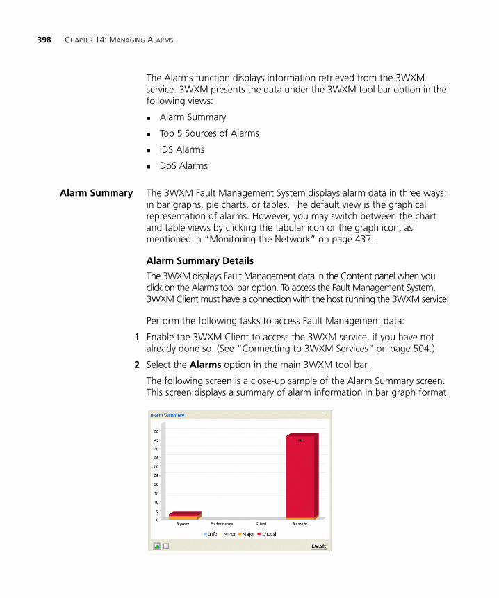
398 CHAPTER 14: MANAGING ALARMS
The Alarms function displays information retrieved from the 3WXM service. 3WXM presents the data under the 3WXM tool bar option in the following views:
Alarm Summary
Top 5 Sources of Alarms
IDS Alarms
DoS Alarms
Alarm Summary The 3WXM Fault Management System displays alarm data in three ways: in bar graphs, pie charts, or tables. The default view is the graphical representation of alarms. However, you may switch between the chart and table views by clicking the tabular icon or the graph icon, as mentioned in “Monitoring the Network” on page 437.
Alarm Summary Details
The 3WXM displays Fault Management data in the Content panel when you click on the Alarms tool bar option. To access the Fault Management System, 3WXM Client must have a connection with the host running the 3WXM service.
Perform the following tasks to access Fault Management data:
1 Enable the 3WXM Client to access the 3WXM service, if you have not already done so. (See “Connecting to 3WXM Services” on page 504.)
2 Select the Alarms option in the main 3WXM tool bar.
The following screen is a close-up sample of the Alarm Summary screen. This screen displays a summary of alarm information in bar graph format.
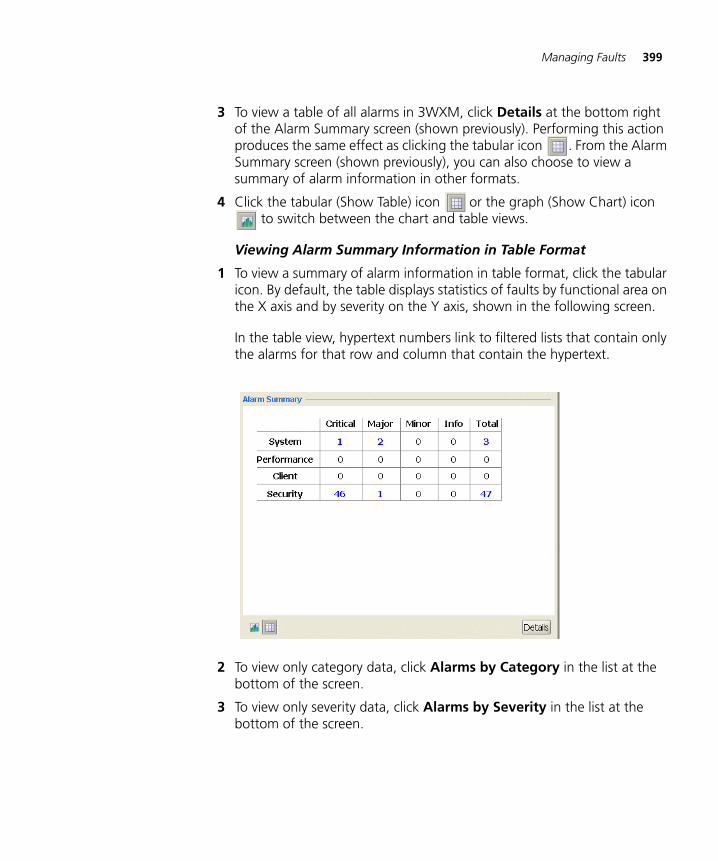
Managing Faults 399
3 To view a table of all alarms in 3WXM, click Details at the bottom right of the Alarm Summary screen (shown previously). Performing this action produces the same effect as clicking the tabular icon . From the Alarm Summary screen (shown previously), you can also choose to view a summary of alarm information in other formats.
4 Click the tabular (Show Table) icon or the graph (Show Chart) icon to switch between the chart and table views.
Viewing Alarm Summary Information in Table Format
1 To view a summary of alarm information in table format, click the tabular icon. By default, the table displays statistics of faults by functional area on the X axis and by severity on the Y axis, shown in the following screen.
In the table view, hypertext numbers link to filtered lists that contain only the alarms for that row and column that contain the hypertext.
2 To view only category data, click Alarms by Category in the list at the bottom of the screen.
3 To view only severity data, click Alarms by Severity in the list at the bottom of the screen.
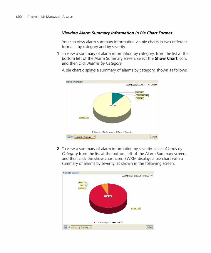
400 CHAPTER 14: MANAGING ALARMS
Viewing Alarm Summary Information in Pie Chart Format
You can view alarm summary information via pie charts in two different formats: by category and by severity.
1 To view a summary of alarm information by category, from the list at the bottom left of the Alarm Summary screen, select the Show Chart icon, and then click Alarms by Category.
A pie chart displays a summary of alarms by category, shown as follows.
2 To view a summary of alarm information by severity, select Alarms by Category from the list at the bottom left of the Alarm Summary screen, and then click the show chart icon. 3WXM displays a pie chart with a summary of alarms by severity, as shown in the following screen.
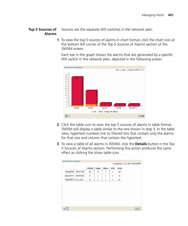
Managing Faults 401
Top 5 Sources ofAlarms
Sources are the separate WX switches in the network plan.
1 To view the top 5 sources of alarms in chart format, click the chart icon at the bottom left corner of the Top 5 Sources of Alarms section of the 3WXM screen.
Each bar in the graph shows the alarms that are generated by a specific WX switch in the network plan, depicted in the following screen.
2 Click the table icon to view the top 5 sources of alarms in table format. 3WXM will display a table similar to the one shown in step 3. In the table view, hypertext numbers link to filtered lists that contain only the alarms for that row and column that contain the hypertext.
3 To view a table of all alarms in 3WXM, click the Details button in the Top 5 Sources of Alarms section. Performing this action produces the same effect as clicking the show table icon.
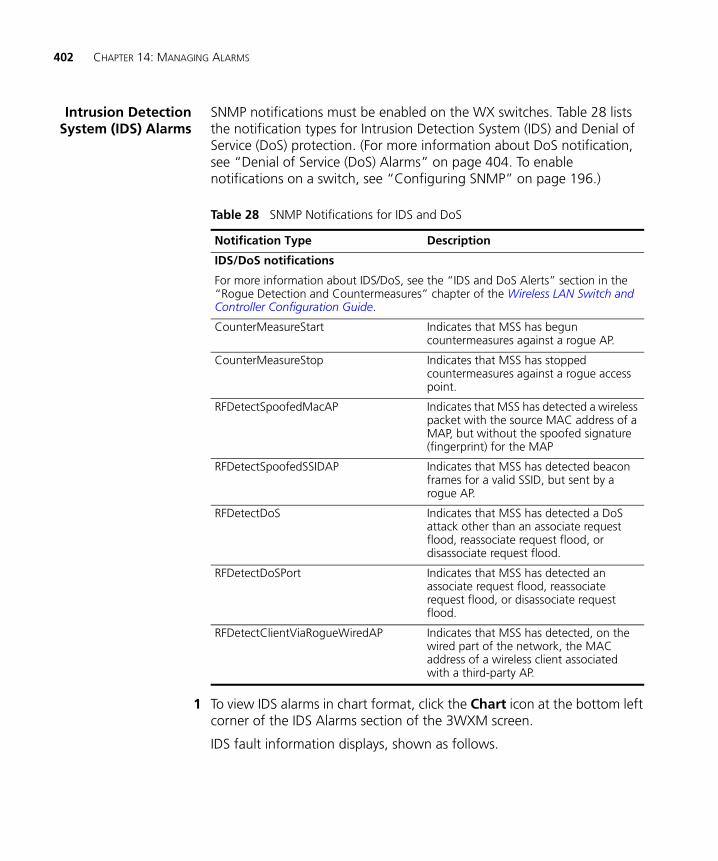
402 CHAPTER 14: MANAGING ALARMS
Intrusion DetectionSystem (IDS) Alarms
SNMP notifications must be enabled on the WX switches. Table 28 lists the notification types for Intrusion Detection System (IDS) and Denial of Service (DoS) protection. (For more information about DoS notification, see “Denial of Service (DoS) Alarms” on page 404. To enable notifications on a switch, see “Configuring SNMP” on page 196.)
1 To view IDS alarms in chart format, click the Chart icon at the bottom left corner of the IDS Alarms section of the 3WXM screen.
IDS fault information displays, shown as follows.
Table 28 SNMP Notifications for IDS and DoS
Notification Type Description
IDS/DoS notifications
For more information about IDS/DoS, see the “IDS and DoS Alerts” section in the “Rogue Detection and Countermeasures” chapter of the Wireless LAN Switch and Controller Configuration Guide.
CounterMeasureStart Indicates that MSS has begun countermeasures against a rogue AP.
CounterMeasureStop Indicates that MSS has stopped countermeasures against a rogue access point.
RFDetectSpoofedMacAP Indicates that MSS has detected a wireless packet with the source MAC address of a MAP, but without the spoofed signature (fingerprint) for the MAP
RFDetectSpoofedSSIDAP Indicates that MSS has detected beacon frames for a valid SSID, but sent by a rogue AP.
RFDetectDoS Indicates that MSS has detected a DoS attack other than an associate request flood, reassociate request flood, or disassociate request flood.
RFDetectDoSPort Indicates that MSS has detected an associate request flood, reassociate request flood, or disassociate request flood.
RFDetectClientViaRogueWiredAP Indicates that MSS has detected, on the wired part of the network, the MAC address of a wireless client associated with a third-party AP.
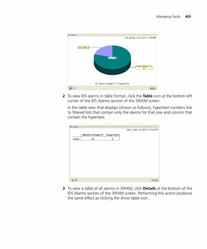
Managing Faults 403
2 To view IDS alarms in table format, click the Table icon at the bottom left corner of the IDS Alarms section of the 3WXM screen.
In the table view that displays (shown as follows), hypertext numbers link to filtered lists that contain only the alarms for that row and column that contain the hypertext.
3 To view a table of all alarms in 3WXM, click Details at the bottom of the IDS Alarms section of the 3WXM screen. Performing this action produces the same effect as clicking the show table icon.
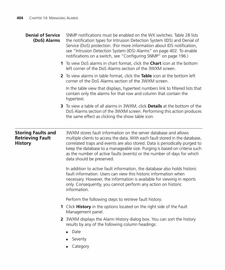
404 CHAPTER 14: MANAGING ALARMS
Denial of Service(DoS) Alarms
SNMP notifications must be enabled on the WX switches. Table 28 lists the notification types for Intrusion Detection System (IDS) and Denial of Service (DoS) protection. (For more information about IDS notification, see “Intrusion Detection System (IDS) Alarms” on page 402. To enable notifications on a switch, see “Configuring SNMP” on page 196.)
1 To view DoS alarms in chart format, click the Chart icon at the bottom left corner of the DoS Alarms section of the 3WXM screen.
2 To view alarms in table format, click the Table icon at the bottom left corner of the DoS Alarms section of the 3WXM screen.
In the table view that displays, hypertext numbers link to filtered lists that contain only the alarms for that row and column that contain the hypertext.
3 To view a table of all alarms in 3WXM, click Details at the bottom of the DoS Alarms section of the 3WXM screen. Performing this action produces the same effect as clicking the show table icon.
Storing Faults and Retrieving Fault History
3WXM stores fault information on the server database and allows multiple clients to access the data. With each fault stored in the database, correlated traps and events are also stored. Data is periodically purged to keep the database to a manageable size. Purging is based on criteria such as the number of active faults (events) or the number of days for which data should be preserved.
In addition to active fault information, the database also holds historic fault information. Users can view this historic information when necessary. However, the information is available for viewing in reports only. Consequently, you cannot perform any action on historic information.
Perform the following steps to retrieve fault history:
1 Click History in the options located on the right side of the Fault Management panel.
2 3WXM displays the Alarm History dialog box. You can sort the history results by any of the following column headings:
Date
Severity
Category
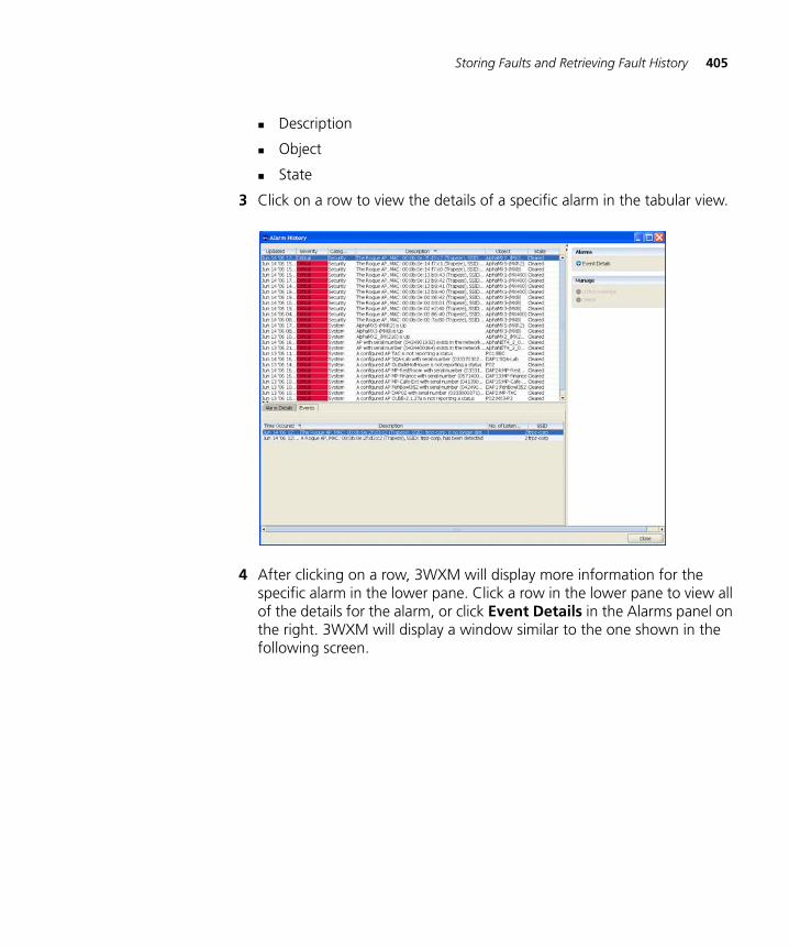
Storing Faults and Retrieving Fault History 405
Description
Object
State
3 Click on a row to view the details of a specific alarm in the tabular view.
4 After clicking on a row, 3WXM will display more information for the specific alarm in the lower pane. Click a row in the lower pane to view all of the details for the alarm, or click Event Details in the Alarms panel on the right. 3WXM will display a window similar to the one shown in the following screen.
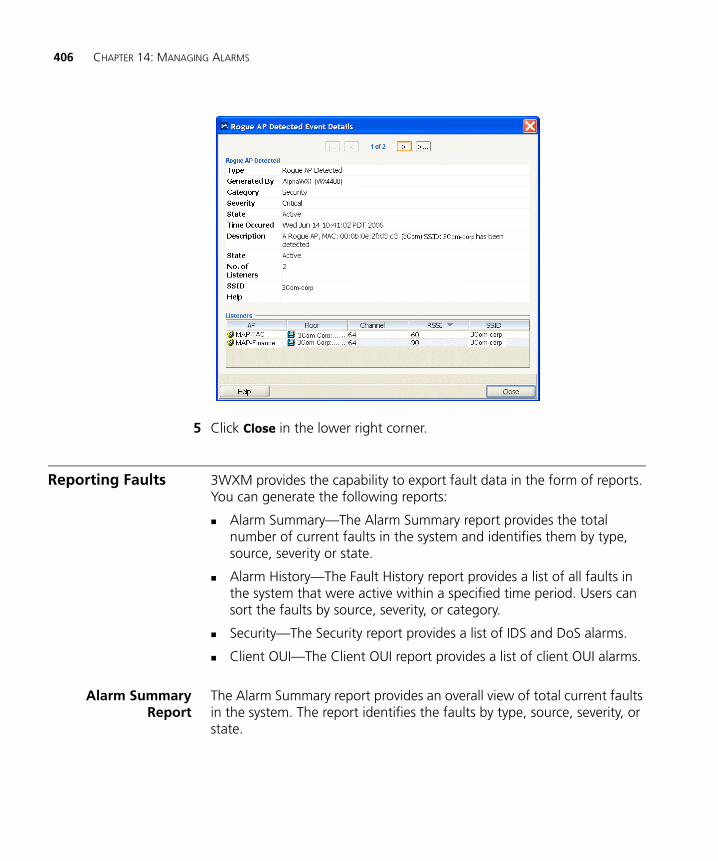
406 CHAPTER 14: MANAGING ALARMS
5 Click Close in the lower right corner.
Reporting Faults 3WXM provides the capability to export fault data in the form of reports. You can generate the following reports:
Alarm Summary—The Alarm Summary report provides the total number of current faults in the system and identifies them by type, source, severity or state.
Alarm History—The Fault History report provides a list of all faults in the system that were active within a specified time period. Users can sort the faults by source, severity, or category.
Security—The Security report provides a list of IDS and DoS alarms.
Client OUI—The Client OUI report provides a list of client OUI alarms.
Alarm SummaryReport
The Alarm Summary report provides an overall view of total current faults in the system. The report identifies the faults by type, source, severity, or state.
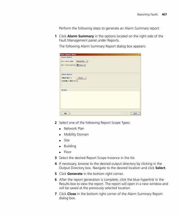
Reporting Faults 407
Perform the following steps to generate an Alarm Summary report:
1 Click Alarm Summary in the options located on the right side of the Fault Management panel under Reports.
The following Alarm Summary Report dialog box appears:
2 Select one of the following Report Scope Types:
Network Plan
Mobility Domain
Site
Building
Floor
3 Select the desired Report Scope Instance in the list.
4 If necessary, browse to the desired output directory by clicking in the Output Directory box. Navigate to the desired location and click Select.
5 Click Generate in the bottom right corner.
6 After the report generation is complete, click the blue hyperlink in the Results box to view the report. The report will open in a new window and will be saved at the previously selected location.
7 Click Close in the bottom right corner of the Alarm Summary Report dialog box.
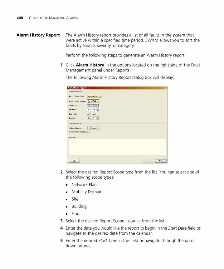
408 CHAPTER 14: MANAGING ALARMS
Alarm History Report The Alarm History report provides a list of all faults in the system that were active within a specified time period. 3WXM allows you to sort the faults by source, severity, or category.
Perform the following steps to generate an Alarm History report:
1 Click Alarm History in the options located on the right side of the Fault Management panel under Reports.
The following Alarm History Report dialog box will display:
2 Select the desired Report Scope type from the list. You can select one of the following scope types:
Network Plan
Mobility Domain
Site
Building
Floor
3 Select the desired Report Scope instance from the list.
4 Enter the date you would like the report to begin in the Start Date field or navigate to the desired date from the calendar.
5 Enter the desired Start Time in the field or navigate through the up or down arrows.
Reporting Faults 409
6 Enter the date you would like the report to end in the End Date field or navigate to the desired date from the calendar.
7 Enter the desired End Time in the field or navigate through the up or down arrows.
8 If necessary, browse to the desired output directory in the Output Directory box. Navigate to the desired location and click Select.
9 Click Generate in the bottom right corner.
10 After generating the report, click the blue hyperlink in the Results box to view the report. 3WXM opens the report in a new window and saves it at the previously selected location.
11 Click Close in the bottom right corner of the Alarm Summary Report dialog box.

410 CHAPTER 14: MANAGING ALARMS
15 USING THE EVENT LOG
3WXM maintains a log of system events. The log contains messages generated by the following:
WX switches in the network plan—messages generated by the WX switches in the network plan that are being monitored by the 3WXM service
3WXM Services—messages generated by the 3WXM server the client is in communication with
3WXM Client—messages generated by the instance of the 3WXM Client you are using
Displaying the Event Log
To display the event log, select Tools > Events from the menu bar in the main 3WXM window.
Event messages are displayed on top. The bottom section allows you to filter the display.
By default, only the messages generated by the 3WXM Client are displayed. Messages are displayed for all severities and for all log facilities.
Toolbar Options Table 29 lists the options on the toolbar for the Event log. These options are in addition to the standard toolbar options. (See “Tool Bar Options” on page 42.)
Table 29 Toolbar Options for Events Tab
Option Description
Export Displays the Export Data dialog box, which enables you to save log data into a file.
Refresh Refreshes event data.
Display Event Details Displays details for the currently selected message.
Display Filters Toggles display of the filter tabs.
412 CHAPTER 15: USING THE EVENT LOG
Refreshing Event Data
By default, the event data is refreshed whenever the 3WXM Client generates a new message for itself, or receives a new message from the 3WXM Services.
To disable automatic refreshing of events, clear the Auto-update checkbox and click Apply. (The checkbox is located on the Filters tab.)
To manually refresh events at any time, click on the toolbar for the Event log.
Reviewing Event Details
To see the details for a specific event, select the event. Event details appear in the Details tab.
Filtering Event Messages
You can limit the events you see in the Event tab by using predefined filters in 3WXM or by specifying filter criteria based on content, facility, or severity. You can save specified filter criteria as a stored filter.
Using PredefinedEvent Filters
To use predefined filters, select one of the following from the Name list in the Stored Filters group box:
All Entries—Shows all entries in the log.
3WXM—Shows only 3WXM Client events.
Server—Shows only 3WXM Services events.
Today—Shows only events that occurred today.
Last 24 Hours—Shows only events that occurred in the last 24 hours.
Last 500 Entries—Shows only the last 500 entries in the log.
Filters specific to the WX switches. For example, if you have a WX switch named wx1, you see a filter named WX ‘wx1’ in the list.
You now see the log entries in Event tab that match the criteria of the filter that you chose.
Filtering Event Messages 413
Filtering Events byContent
When using the predefined filters, you can limit the events you see in Event tab by specifying criteria such as IP address, date, or text in the log message. You can use advanced filters to further limit the events you see.
To filter messages by content
1 In the Event Source box, type an event source name or part of an event source name. You can type more than one name or partial name.
For example, type 3wxm If you want to see only 3wxm events. If you have a WX named wx1, type wx1 to see only events related to wx1. To see events related to all WX switches whose names start with wx, type wx.
To set the search criteria, select one of the following:
contains the string—The filter looks for messages that contain the entire string you entered.
contains all of the strings—The filter looks for messages that contain all of the entered strings. Select this option if you enter more than one string and want to see messages that contain all of the strings.
contains at least one of the strings—The filter looks for messages that contain one or more of the strings you entered. Select this option if you enter more than one string and want to see messages that contain any of the strings.
2 In the Message box, type a word or exact phrase used in a message.
For example, if you type vlan, you see all events that contain vlan in the message.
Set the search criteria by selecting contains the string, contains all of the strings, or contains at least one of the strings.
3 In the IP Address box, type an IP address or a partial IP address.
For example, if you type 10.20, you see all events that pertain to IP addresses containing the string 10.20.
Set the search criteria by selecting contains the string, contains all of the strings, or contains at least one of the strings.
4 In the Date list, select one of the following to filter events by time:
Any—No events are filtered based on time criteria.
Before—Only events that occurred before a specified time.
414 CHAPTER 15: USING THE EVENT LOG
In the Start box, click the arrow to use the calendar to specify the day, month, and year.
Specify the end time.
After—Only events that occurred after a specified time
In the Start box, click the arrow to use the calendar to specify the day, month, and year.
Specify the starting time.
Between—Only events that occurred between specified times
In the Start box, click the arrow to use the calendar to specify the day, month, and year.
Specify the starting time.
In the End box, click the arrow to use the calendar to specify the day, month, and year.
Specify the end time.
5 In the Show list, select one of the following:
All—To see all log entries
Last—To see a specified number of entries at the bottom of the log
First—To see a specified number of entries at the top of the log
If you selected All, go to step 7. Otherwise, go to the next step.
6 In the Matching Entries box, type the number of log entries you want to see.
The maximum number of entries you can specify depends on the number of entries in the log.
7 Click Apply to filter out the unwanted entries from the display.
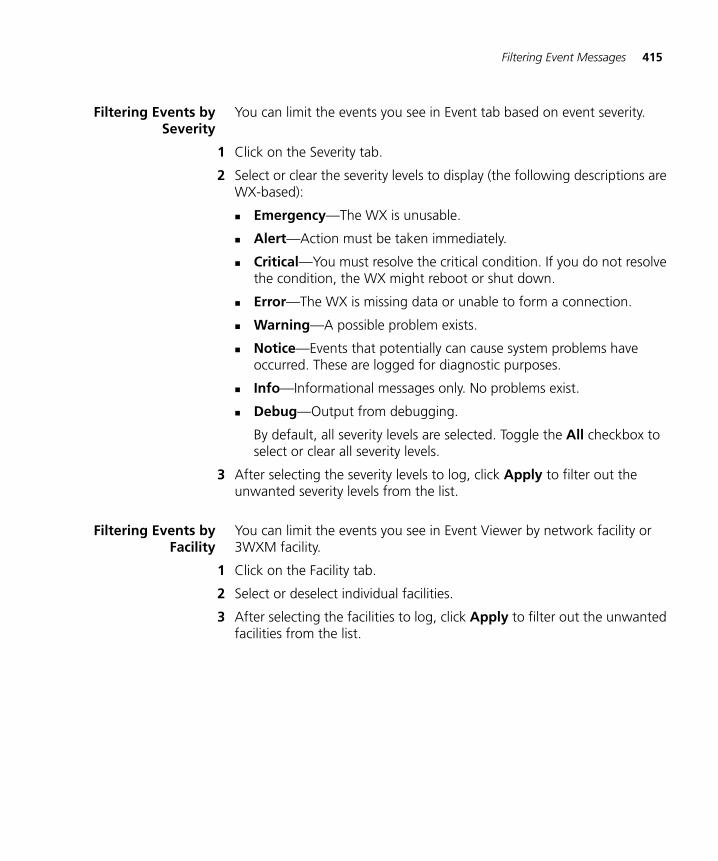
Filtering Event Messages 415
Filtering Events bySeverity
You can limit the events you see in Event tab based on event severity.
1 Click on the Severity tab.
2 Select or clear the severity levels to display (the following descriptions are WX-based):
Emergency—The WX is unusable.
Alert—Action must be taken immediately.
Critical—You must resolve the critical condition. If you do not resolve the condition, the WX might reboot or shut down.
Error—The WX is missing data or unable to form a connection.
Warning—A possible problem exists.
Notice—Events that potentially can cause system problems have occurred. These are logged for diagnostic purposes.
Info—Informational messages only. No problems exist.
Debug—Output from debugging.
By default, all severity levels are selected. Toggle the All checkbox to select or clear all severity levels.
3 After selecting the severity levels to log, click Apply to filter out the unwanted severity levels from the list.
Filtering Events byFacility
You can limit the events you see in Event Viewer by network facility or 3WXM facility.
1 Click on the Facility tab.
2 Select or deselect individual facilities.
3 After selecting the facilities to log, click Apply to filter out the unwanted facilities from the list.
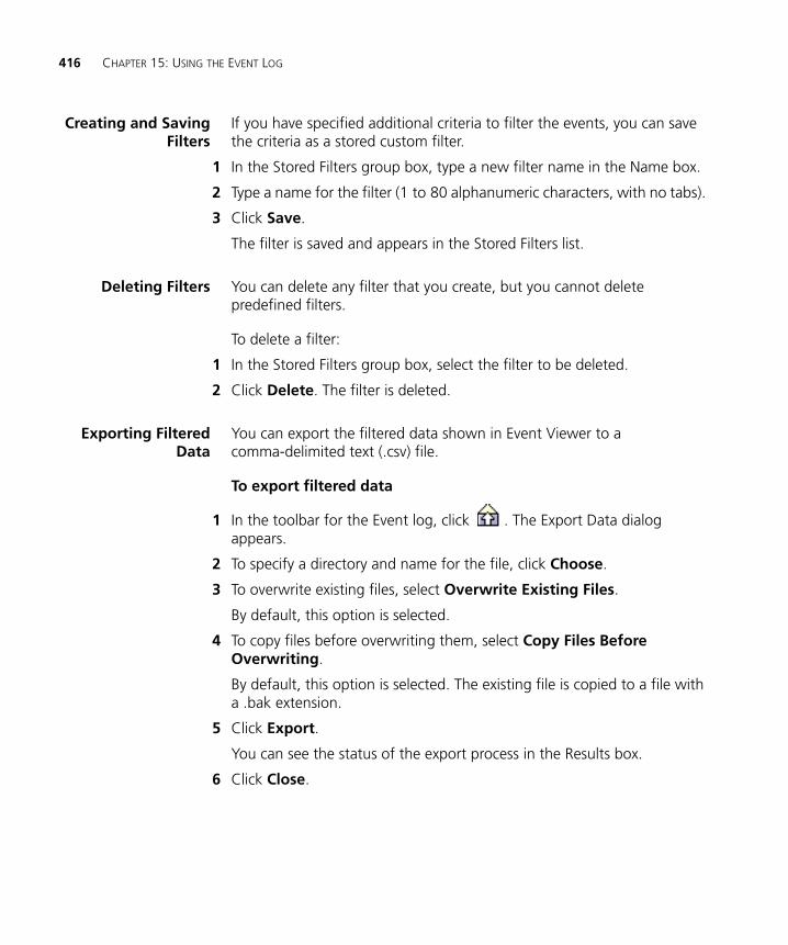
416 CHAPTER 15: USING THE EVENT LOG
Creating and SavingFilters
If you have specified additional criteria to filter the events, you can save the criteria as a stored custom filter.
1 In the Stored Filters group box, type a new filter name in the Name box.
2 Type a name for the filter (1 to 80 alphanumeric characters, with no tabs).
3 Click Save.
The filter is saved and appears in the Stored Filters list.
Deleting Filters You can delete any filter that you create, but you cannot delete predefined filters.
To delete a filter:
1 In the Stored Filters group box, select the filter to be deleted.
2 Click Delete. The filter is deleted.
Exporting FilteredData
You can export the filtered data shown in Event Viewer to a comma-delimited text (.csv) file.
To export filtered data
1 In the toolbar for the Event log, click . The Export Data dialog appears.
2 To specify a directory and name for the file, click Choose.
3 To overwrite existing files, select Overwrite Existing Files.
By default, this option is selected.
4 To copy files before overwriting them, select Copy Files Before Overwriting.
By default, this option is selected. The existing file is copied to a file with a .bak extension.
5 Click Export.
You can see the status of the export process in the Results box.
6 Click Close.
16 GENERATING REPORTS
This chapter describes the reports you can generate with 3WXM:
Inventory
Mobility Domain Configuration
WX Configuration
Client Summary
Client Details
Client Errors
Network Usage (Radio Traffic)
RF Summary
Radio Details
Network Usage (Port Traffic)
Rogue Details
Rogue Summary
Site Survey
Work Order
Alarm Summary
Alarm History
Security
Client OUI
When you generate a report, you can specify the scope of the report and the location where 3WXM saves the report. Some reports also have additional options. 3WXM saves the reports in HTML format.
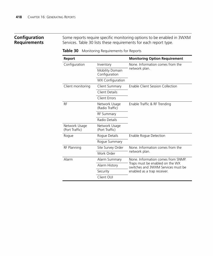
418 CHAPTER 16: GENERATING REPORTS
Configuration Requirements
Some reports require specific monitoring options to be enabled in 3WXM Services. Table 30 lists these requirements for each report type.
Table 30 Monitoring Requirements for Reports
Report Monitoring Option Requirement
Configuration Inventory None. Information comes from the network plan.Mobility Domain
Configuration
WX Configuration
Client monitoring Client Summary Enable Client Session Collection
Client Details
Client Errors
RF Network Usage (Radio Traffic)
Enable Traffic & RF Trending
RF Summary
Radio Details
Network Usage (Port Traffic)
Network Usage (Port Traffic)
Rogue Rogue Details Enable Rogue Detection
Rogue Summary
RF Planning Site Survey Order None. Information comes from the network plan.Work Order
Alarm Alarm Summary None. Information comes from SNMP. Traps must be enabled on the WX switches and 3WXM Services must be enabled as a trap receiver.
Alarm History
Security
Client OUI
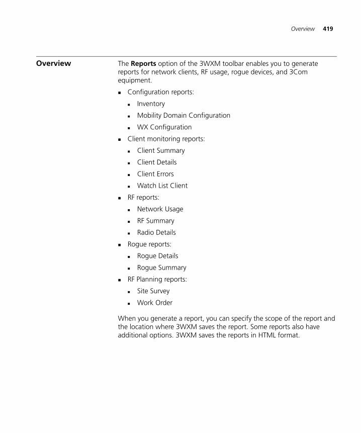
Overview 419
Overview The Reports option of the 3WXM toolbar enables you to generate reports for network clients, RF usage, rogue devices, and 3Com equipment.
Configuration reports:
Inventory
Mobility Domain Configuration
WX Configuration
Client monitoring reports:
Client Summary
Client Details
Client Errors
Watch List Client
RF reports:
Network Usage
RF Summary
Radio Details
Rogue reports:
Rogue Details
Rogue Summary
RF Planning reports:
Site Survey
Work Order
When you generate a report, you can specify the scope of the report and the location where 3WXM saves the report. Some reports also have additional options. 3WXM saves the reports in HTML format.
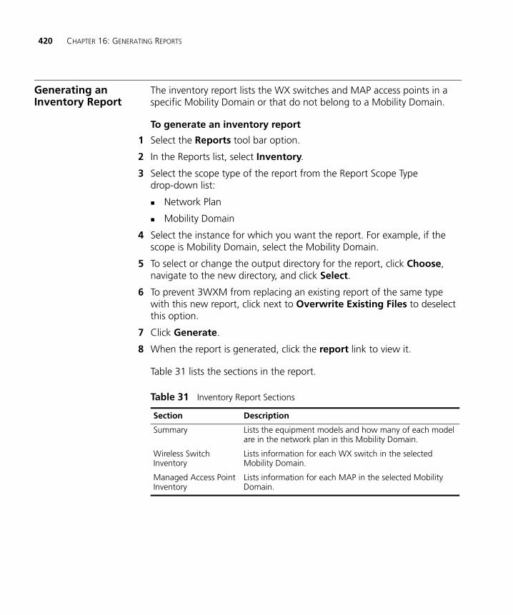
420 CHAPTER 16: GENERATING REPORTS
Generating an Inventory Report
The inventory report lists the WX switches and MAP access points in a specific Mobility Domain or that do not belong to a Mobility Domain.
To generate an inventory report
1 Select the Reports tool bar option.
2 In the Reports list, select Inventory.
3 Select the scope type of the report from the Report Scope Type drop-down list:
Network Plan
Mobility Domain
4 Select the instance for which you want the report. For example, if the scope is Mobility Domain, select the Mobility Domain.
5 To select or change the output directory for the report, click Choose, navigate to the new directory, and click Select.
6 To prevent 3WXM from replacing an existing report of the same type with this new report, click next to Overwrite Existing Files to deselect this option.
7 Click Generate.
8 When the report is generated, click the report link to view it.
Table 31 lists the sections in the report.
Table 31 Inventory Report Sections
Section Description
Summary Lists the equipment models and how many of each model are in the network plan in this Mobility Domain.
Wireless Switch Inventory
Lists information for each WX switch in the selected Mobility Domain.
Managed Access Point Inventory
Lists information for each MAP in the selected Mobility Domain.
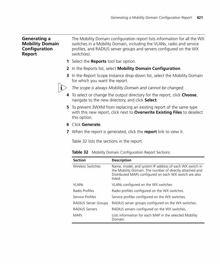
Generating a Mobility Domain Configuration Report 421
Generating a Mobility Domain Configuration Report
The Mobility Domain configuration report lists information for all the WX switches in a Mobility Domain, including the VLANs, radio and service profiles, and RADIUS server groups and servers configured on the WX switch(es).
1 Select the Reports tool bar option.
2 In the Reports list, select Mobility Domain Configuration.
3 In the Report Scope Instance drop-down list, select the Mobility Domain for which you want the report.
The scope is always Mobility Domain and cannot be changed.
4 To select or change the output directory for the report, click Choose, navigate to the new directory, and click Select.
5 To prevent 3WXM from replacing an existing report of the same type with this new report, click next to Overwrite Existing Files to deselect this option.
6 Click Generate.
7 When the report is generated, click the report link to view it.
Table 32 lists the sections in the report.
Table 32 Mobility Domain Configuration Report Sections
Section Description
Wireless Switches Name, model, and system IP address of each WX switch in the Mobility Domain. The number of directly attached and Distributed MAPs configured on each WX switch are also listed.
VLANs VLANs configured on the WX switches.
Radio Profiles Radio profiles configured on the WX switches.
Service Profiles Service profiles configured on the WX switches.
RADIUS Server Groups RADIUS server groups configured on the WX switches.
RADIUS Servers RADIUS servers configured on the WX switches.
MAPs Lists information for each MAP in the selected Mobility Domain.
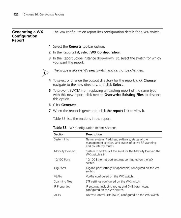
422 CHAPTER 16: GENERATING REPORTS
Generating a WX Configuration Report
The WX configuration report lists configuration details for a WX switch.
1 Select the Reports toolbar option.
2 In the Reports list, select WX Configuration.
3 In the Report Scope Instance drop-down list, select the switch for which you want the report.
The scope is always Wireless Switch and cannot be changed.
4 To select or change the output directory for the report, click Choose, navigate to the new directory, and click Select.
5 To prevent 3WXM from replacing an existing report of the same type with this new report, click next to Overwrite Existing Files to deselect this option.
6 Click Generate.
7 When the report is generated, click the report link to view it.
Table 33 lists the sections in the report.
Table 33 WX Configuration Report Sections
Section Description
System Info Name, system IP address, software, states of the management services, and states of active RF scanning and countermeasures.
Mobility Domain System IP address of the seed for the Mobility Domain the WX switch is in.
10/100 Ports 10/100 Ethernet port settings configured on the WX switch.
Gig Ports Gigabit port settings (if applicable) configured on the WX switch.
VLANs VLANs configured on the WX switch.
Spanning Tree STP settings configured on the WX switch.
IP Properties IP settings, including routes and DNS parameters, configured on the WX switch.
ACLs Access Control Lists (ACLs) configured on the WX switch.
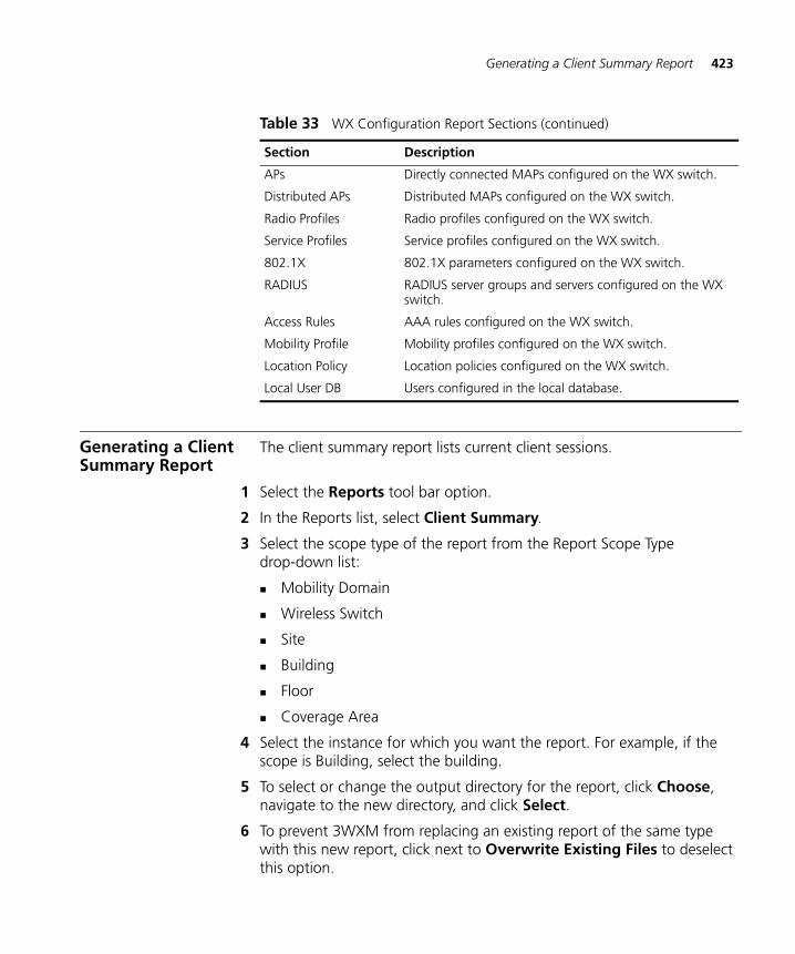
Generating a Client Summary Report 423
Generating a Client Summary Report
The client summary report lists current client sessions.
1 Select the Reports tool bar option.
2 In the Reports list, select Client Summary.
3 Select the scope type of the report from the Report Scope Type drop-down list:
Mobility Domain
Wireless Switch
Site
Building
Floor
Coverage Area
4 Select the instance for which you want the report. For example, if the scope is Building, select the building.
5 To select or change the output directory for the report, click Choose, navigate to the new directory, and click Select.
6 To prevent 3WXM from replacing an existing report of the same type with this new report, click next to Overwrite Existing Files to deselect this option.
APs Directly connected MAPs configured on the WX switch.
Distributed APs Distributed MAPs configured on the WX switch.
Radio Profiles Radio profiles configured on the WX switch.
Service Profiles Service profiles configured on the WX switch.
802.1X 802.1X parameters configured on the WX switch.
RADIUS RADIUS server groups and servers configured on the WX switch.
Access Rules AAA rules configured on the WX switch.
Mobility Profile Mobility profiles configured on the WX switch.
Location Policy Location policies configured on the WX switch.
Local User DB Users configured in the local database.
Table 33 WX Configuration Report Sections (continued)
Section Description
424 CHAPTER 16: GENERATING REPORTS
7 Click Generate.
8 When the report is generated, click the report link to view it.
The client summary report contains the following sections:
Session Summary
Total Num Sessions
Average SNR
Average RSSI
SSID Summary
Access Type Summary
Top Bandwidth Sessions
Low RSSI Sessions
Low SNR Sessions
Generating a Client Details Report
The client details report lists details about current client sessions.
1 Select the Reports tool bar option.
2 In the Reports list, select Client Details.
3 Click Add to add a report filter. The filter configuration fields are activated.
4 Click on the Select field, and select one of the following from the drop-down list:
User Name
IP Address
MAC Address
5 Click on the Value field. Erase the text in the field and type the username, IP address, or MAC address of the user, depending on the selection criterion you specified in step 4.
6 Press Enter to complete the filter.
7 Repeat step 3 through step 6 for each user you want to display details for.
8 To select or change the output directory for the report, click Choose, navigate to the new directory, and click Select.
Generating a Client Errors Report 425
9 To prevent 3WXM from replacing an existing report of the same type with this new report, click next to Overwrite Existing Files to deselect this option.
10 Click Generate.
11 When the report is generated, click the report link to view it.
The client details report contains the following sections:
Session Properties
Location History
Session Statistics
Current AP Statistics
Lifetime AP Statistics
Generating a Client Errors Report
The client errors report lists error statistics for current client sessions.
1 Select the Reports tool bar option.
2 In the Reports list, select Client Errors.
3 Select the scope type of the report from the Report Scope Type list:
Mobility Domain
Wireless Switch
Site
Building
Floor
Coverage Area
4 Select the instance for which you want the report. For example, if the scope is Building, select the building.
5 Select the time period for the report:
1 Hour
24 Hours
7 Days
30 Days
6 To select or change the output directory for the report, click Choose, navigate to the new directory, and click Select.
426 CHAPTER 16: GENERATING REPORTS
7 To prevent 3WXM from replacing an existing report of the same type with this new report, click next to Overwrite Existing Files to deselect this option.
8 Click Generate.
9 When the report is generated, click the report link to view it.
The client errors report contains the following sections:
Cumulative errors for the scope of the report
Client errors on individual WX switches
Generating an RF Network Usage Report
This network usage report shows radio traffic statistics.
1 Select the Reports tool bar option.
2 In the Reports list, select Network Usage (Radio Traffic).
3 Select the scope type of the report from the Report Scope Type drop-down list:
Mobility Domain
Wireless Switch
Site
Building
Floor
Coverage Area
4 Select the instance for which you want the report. For example, if the scope is Building, select the building.
5 Select the time period for the report:
1 Hour
24 Hours
7 Days
30 Days
6 To select or change the output directory for the report, click Choose, navigate to the new directory, and click Select.
Generating an RF Summary Report 427
7 To prevent 3WXM from replacing an existing report of the same type with this new report, click next to Overwrite Existing Files to deselect this option.
8 Click Generate.
9 When the report is generated, click the report link to view it.
The network usage report contains the following sections:
Cumulative statistics for the scope of the report
Usage statistics on individual WX switches
Generating an RF Summary Report
The RF summary report lists summary RF statistics.
1 Select the Reports tool bar option.
2 In the Reports list, select RF Summary.
3 Select the scope type of the report from the Report Scope Type drop-down list:
Mobility Domain
Wireless Switch
Site
Building
Floor
Coverage Area
4 Select the instance for which you want the report. For example, if the scope is Building, select the building.
5 Select the time period for the report:
1 Hour
24 Hours
7 Days
30 Days
6 To select or change the output directory for the report, click Choose, navigate to the new directory, and click Select.
428 CHAPTER 16: GENERATING REPORTS
7 To prevent 3WXM from replacing an existing report of the same type with this new report, click next to Overwrite Existing Files to deselect this option.
8 Click Generate.
9 When the report is generated, click the report link to view it.
The RF summary report contains the following sections:
Cumulative data for the scope of the report
Detailed data for each WX switch within the scope of the report
Generating a Radio Details Report
The radio details report lists details about an individual radio.
1 Select the Reports tool bar option.
2 In the Reports list, select Radio Details.
3 Select the radio for which you want the report.
The scope is always MAP Radio and cannot be changed.
4 Select the time period for the report:
1 Hour
24 Hours
7 Days
30 Days
5 To select or change the output directory for the report, click Choose, navigate to the new directory, and click Select.
6 To prevent 3WXM from replacing an existing report of the same type with this new report, click next to Overwrite Existing Files to deselect this option.
7 Click Generate.
8 When the report is generated, click the report link to view it.
Generating a Traffic Report 429
Generating a Traffic Report
This network usage report shows port traffic statistics.
1 Select the Reports tool bar option.
2 In the Reports list, select Network Usage (Port Traffic).
3 Select the scope type of the report from the Report Scope Type drop-down list:
Network Plan
Mobility Domain
Mobility Exchange
4 Select the instance for which you want the report. For example, if the scope is Mobility Domain, select the Mobility Domain.
5 Select the time period for the report:
1 Hour
24 Hours
7 Days
30 Days
6 To select or change the output directory for the report, click Choose, navigate to the new directory, and click Select.
7 To prevent 3WXM from replacing an existing report of the same type with this new report, click next to Overwrite Existing Files to deselect this option.
8 Click Generate.
When the report is generated, click the report link to view it.
430 CHAPTER 16: GENERATING REPORTS
Generating a Rogue Details Report
The rogue details report lists detailed information about rogue devices.
1 Select the Reports tool bar option.
2 In the Reports list, select Rogue Details.
3 Click Add to add a report filter. The filter configuration fields are activated.
4 Click on the Select field, and select MAC Address.
5 Click on the Value field. Erase the text in the field and type the BSSID of the rogue.
6 Press Enter to complete the filter.
7 Repeat step 3 through step 6 for each user you want to display details for.
8 To select or change the output directory for the report, click Choose, navigate to the new directory, and click Select.
9 To prevent 3WXM from replacing an existing report of the same type with this new report, click next to Overwrite Existing Files to deselect this option.
10 Click Generate.
11 When the report is generated, click the report link to view it.
Generating a Rogue Summary Report
The rogue summary report lists information about rogues.
1 Select the Reports tool bar option.
2 In the Reports list, select Rogue Summary.
3 Select the scope type of the report from the Report Scope Type drop-down list:
Mobility Domain
Site
Building
Floor
4 Select the instance for which you want the report. For example, if the scope is Building, select the building.
Generating a Rogue Summary Report 431
5 Select the time period for the report:
1 Hour
24 Hours
7 Days
30 Days
6 To specify the rogue type, click on the Value field in the Report Filter area of the dialog, and select one of the following from the drop-down list:
Rogue
Interfering
Ad-hoc
All (This option displays all three types: rogue, interfering, and ad-hoc.)
The default is Rogue.
7 To select or change the output directory for the report, click on the button next to output directory, navigate to the new directory, and click Select.
8 To prevent 3WXM from replacing an existing report of the same type with this new report, click next to Overwrite Existing Files to deselect this option.
9 Click Generate.
10 When the report is generated, click the report link to view it.
The report lists the BSSIDs of the rogues detected by each WX switch. The report also shows graphs of the distribution of rogues on the WX switches, and of trend data.
432 CHAPTER 16: GENERATING REPORTS
Generating a Site Survey Order
The site survey order contains the locations and MAC addresses of the line-of-site (LOS) points for use when conducting a site survey, and also provides a GIF image of the floor.
For the site survey order to be meaningful, you must specify the line-of-site (LOS) points first. (See “Importing RF Obstacle Data from a Site Survey” on page 104.)
To generate a site survey order
1 Select the Reports tool bar option.
2 In the Reports list, select Site Survey Order.
3 Select the scope for the work order. You can select the network plan, a site, a building, or an individual floor.
4 Select the language:
English
German
5 To change the output directory for the report, click on the button next to output directory, navigate to the new directory, and click Select.
6 Click Generate.
7 When the report is generated, click View. A browser window containing the report opens.
8 Optionally, select the floor.
9 Click View Site Survey Order. The site survey order appears. LOS point information for the selected floor is displayed.
Scroll down to view the MAC address assignments for the LOS points.
Use the instructions in the Ekahau Site Survey Initial Setup section of the work order to set up the survey.
When you import the floor map into the site survey tool, make sure you use the map name specified in the work order. The site survey data will not appear when you import RF measurements into 3WXM unless the map name is correct.
Generating a Work Order 433
Generating a Work Order
A work order provides all of the necessary information for the physical installation of the 3Com Mobility System. A work order shows where the MAP access points should be installed, WX initial setup configuration information, and projected RSSI information that is useful when verifying the installation.
The work order has meaning only after you add planning information. (See “Planning the 3Com Mobility System” on page 75.)
1 Select the Reports tool bar option.
2 In the Reports list, select Work Order.
3 Select the scope for the work order. You can select the network plan, a site, a building, or an individual floor.
4 Select the options you want to use for the report:
RF Coverage
RSSI Projections
Display Disabled MAPs (only available if RSSI Projections is selected)
Display RF Coverage On Entire Floor (only available if RSSI Projections is selected)
Display Unreachable MAPs (only available if RSSI Projections is selected)
Display MAPs on Other Floors (only available if RSSI Projections is selected)
5 Select the language:
English
German
6 To change the output directory for the report, click on the button next to output directory, navigate to the new directory, and click Select.
7 Click Generate.
8 When the report is generated, click View. A browser window containing the report opens.
9 Optionally, select the floor.
10 Click View Work Order.
434 CHAPTER 16: GENERATING REPORTS
The origin reference point used in work orders to indicate MAP placement is the upper left corner of the coverage area. (Typically, this origin point will not match the origin point used on the floor plan itself.)
Generating an Alarm Summary
The alarm summary report provides a summary of alarms.
1 Select the Reports tool bar option.
2 In the Reports list, select Alarm Summary.
3 Select the scope type of the report from the Report Scope Type drop-down list:
Network Plan
Mobility Domain
Site
Building
Floor
4 Select the instance for which you want the report. For example, if the scope is Building, select the building.
5 To select or change the output directory for the report, click Choose, navigate to the new directory, and click Select.
6 To prevent 3WXM from replacing an existing report of the same type with this new report, click next to Overwrite Existing Files to deselect this option.
7 Click Generate.
8 When the report is generated, click the report link to view it.
Generating an Alarm History
The alarm history report provides a history of alarms.
1 Select the Reports tool bar option.
2 In the Reports list, select Alarm History.
3 Select the scope type of the report from the Report Scope Type drop-down list:
Network Plan
Mobility Domain
Generating a Security Alarm Report 435
Site
Building
Floor
4 Select the instance for which you want the report. For example, if the scope is Building, select the building.
5 Edit or select the start and end dates and times for the history.
6 To select or change the output directory for the report, click Choose, navigate to the new directory, and click Select.
7 To prevent 3WXM from replacing an existing report of the same type with this new report, click next to Overwrite Existing Files to deselect this option.
8 Click Generate.
9 When the report is generated, click the report link to view it.
Generating a Security Alarm Report
The security alarm report provides information about security alarms.
1 Select the Reports tool bar option.
2 In the Reports list, select Security.
3 To select or change the output directory for the report, click Choose, navigate to the new directory, and click Select.
4 To prevent 3WXM from replacing an existing report of the same type with this new report, click next to Overwrite Existing Files to deselect this option.
5 Click Generate.
6 When the report is generated, click the report link to view it.
436 CHAPTER 16: GENERATING REPORTS
Generating an Alarm Report for Client OUIs
The client OUI report provides information about client-related alarms.
1 Select the Reports tool bar option.
2 In the Reports list, select Client OUI.
3 To select or change the output directory for the report, click Choose, navigate to the new directory, and click Select.
4 To prevent 3WXM from replacing an existing report of the same type with this new report, click next to Overwrite Existing Files to deselect this option.
5 Click Generate.
6 When the report is generated, click the report link to view it.
17 MONITORING THE NETWORK
This chapter describes how to use the 3WXM monitoring service. It includes information about monitoring service requirements, accessing monitored data, using the Explore, Status Summary, Client Monitor, RF Monitor, and RF Trends windows, and accessing realtime performance statistics and the event log.
Overview The 3WXM Services regularly checks the status of the network and reports that status to each 3WXM client that is connected to the service. Optionally, the service also receives SNMP traps generated by the WX switches and shows information based on those traps.
The Monitor tab displays information retrieved from the 3WXM Services. Information is presented in the following windows within the Monitor tab:
Status Summary—Shows the high-level status for 3com equipment.
Client Summary—Shows activity, errors, and session information for network clients.
Alarm Summary—Shows faults (alarms) for WX switches.
Traffic Summary—Shows traffic statistics for the network.
Clicking the Details button in any of these views provides more information about the data in the view.
438 CHAPTER 17: MONITORING THE NETWORK
Requirements for Monitoring
To enable the 3WXM service to monitor network data, you or the 3WXM service administrator must specify the WX switches to monitor. The 3WXM service collects data from the switches and updates the information in the views under the Monitor tool bar option for 3WXM clients.
To specify the WX switches to monitor, upload their configuration into 3WXM or add them to the network plan. In addition, enable SNMP traps on the WX switches.
By default, the 3WXM service supplies data to all of the views under the Monitor tool bar option. This data is refreshed at regular intervals, according to the polling interval configured for the 3WXM service. The default polling interval is 5 minutes.
You can optionally disable the 3WXM service from supplying data to specified views. To configure the 3WXM service for monitoring, see “Changing Monitoring Settings” on page 510. To enable SNMP traps on WX switches, see “Configuring SNMP” on page 196.
Network Types There are different types of networks, and the requirements and expectations for network monitoring change depending on the type of network being monitored. The two most commons network types are corporate or campus networks, and distributed networks with remote sites.
Corporate or Campus Networks
Corporate or campus networks have 2 to 32 high-capacity switches, such as WX-4400 devices. These networks can include a high number of APs and clients in a variety of locations, including multiple sites managed by a single 3WXM server. One or more mobility domains can be configured for this network.
For this network, 3WXM has sufficient bandwidth to periodically collect detailed information from all of the switches. With SNMP traps and all trending options enabled, 3WXM will automatically collect data and provide network wide reports on demand. 3WXM will immediately notify the administrator with status and fault information, and the administrator can retrieve data at any time from a single switch or across the network.
Accessing Monitored Data 439
Distributed Networks with Remote Sites
Distributed networks with remote sites have a large number, possibly hundreds, of smaller switches, such as WXR100 or WX1200 devices, spread across a variety of sites; for example, branch offices or a chain of stores. Each site has relatively few APs and clients. The domains might not be configured for mobility because the sites will be geographically distributed, and each site might have only a single switch. You can configure a network domain for this type of network.
For distributed networks, 3WXM will communicate with the WXs over a WAN, and you can turn off automatic data collection for trending, even SNMP traps. The administrator can retrieve some fault and status information, but can control what is collected and how often 3WXM polls the network. With 3WXM, the administrator of a distributed network can monitor and diagnose a single site or WX by collecting data as it is needed.
Accessing Monitored Data
The 3WXM service displays data in the Content panel when you click on the Monitor tool bar option. To access the data, 3WXM client must have a connection with the host running the 3WXM service.
Perform the following tasks to access monitored data:
1 Enable the 3WXM client to access the 3WXM service, if you have not already done so. (See “Connecting to 3WXM Services” on page 504.)
2 Select the Monitor option in the main 3WXM tool bar.
By default, the 3WXM displays the Dashboard view of the Network Plan, as shown in the following figure. (Note that the Network Plan is selected in the Equipment tree of the Organizer panel on the left side of the Dashboard.)
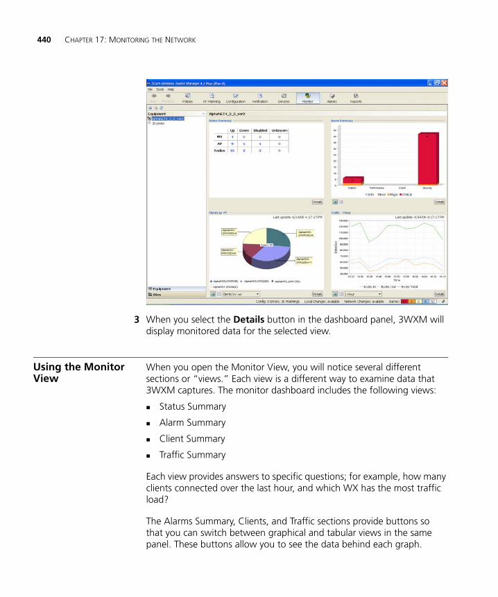
440 CHAPTER 17: MONITORING THE NETWORK
3 When you select the Details button in the dashboard panel, 3WXM will display monitored data for the selected view.
Using the Monitor View
When you open the Monitor View, you will notice several different sections or “views.” Each view is a different way to examine data that 3WXM captures. The monitor dashboard includes the following views:
Status Summary
Alarm Summary
Client Summary
Traffic Summary
Each view provides answers to specific questions; for example, how many clients connected over the last hour, and which WX has the most traffic load?
The Alarms Summary, Clients, and Traffic sections provide buttons so that you can switch between graphical and tabular views in the same panel. These buttons allow you to see the data behind each graph.
Using the Monitor View 441
3WXM automatically selects the appropriate graphical display for the type of data, and displays the data using one of the following graphs:
Line graph
Pie chart
Bar chart
Stacked-bar charts
While 3WXM collects graphical or tabular data, it might take longer to display data in one area than it does in another. Consequently, 3WXM will show the message “Loading data, please wait,” in the chart or table area. However, 3WXM allows you to view data from another view while it collects data from the previously selected view. In other words, 3WXM will load selected data in the background so that you can view corresponding data in another section.
Refresh 3WXM data by clicking the refresh icon in the upper left corner. In addition, you can print any displayed tables and graphs by clicking the print icon in the upper left corner.
Status Summary The Status Summary view is located in the upper left corner of the Content panel and shows the status of the devices in your network. The following list includes some of the information available in the Status Summary view:
Available devices
Inactive devices
Availability status
Alarm status
MAC addresses
Serial numbers
442 CHAPTER 17: MONITORING THE NETWORK
Alarm Summary The Alarm Summary view is located in the upper right corner of the Content panel and shows the current alarms for the selected scope. The alarms are organized by category and alarm type.
3WXM displays the following types of alarms, or faults:
System
Performance
Client
Security
3WXM displays one of the following status modes for each of the previous alarms:
Information
Minor
Major
Critical
Client Summary The Client Summary view is located in the lower left corner of the Content panel and shows different graphs for the following information:
Clients by WX
Clients by SSID
Clients by access type
Clients by time
Top clients
Traffic Summary The Traffic Summary view is located in the lower right corner of the Content panel and shows network usage and summary data. 3WXM shows bytes and packet counter statistics for the following scopes:
Radio
AP
Floor
Building
Site
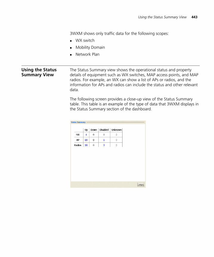
Using the Status Summary View 443
3WXM shows only traffic data for the following scopes:
WX switch
Mobility Domain
Network Plan
Using the Status Summary View
The Status Summary view shows the operational status and property details of equipment such as WX switches, MAP access points, and MAP radios. For example, an WX can show a list of APs or radios, and the information for APs and radios can include the status and other relevant data.
The following screen provides a close-up view of the Status Summary table. This table is an example of the type of data that 3WXM displays in the Status Summary section of the dashboard.
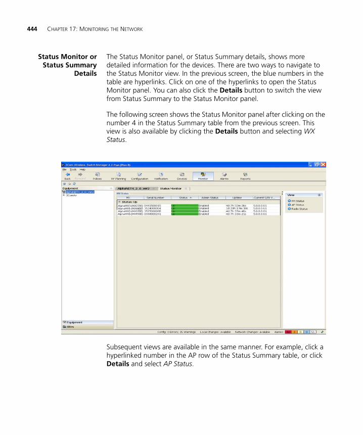
444 CHAPTER 17: MONITORING THE NETWORK
Status Monitor orStatus Summary
Details
The Status Monitor panel, or Status Summary details, shows more detailed information for the devices. There are two ways to navigate to the Status Monitor view. In the previous screen, the blue numbers in the table are hyperlinks. Click on one of the hyperlinks to open the Status Monitor panel. You can also click the Details button to switch the view from Status Summary to the Status Monitor panel.
The following screen shows the Status Monitor panel after clicking on the number 4 in the Status Summary table from the previous screen. This view is also available by clicking the Details button and selecting WX Status.
Subsequent views are available in the same manner. For example, click a hyperlinked number in the AP row of the Status Summary table, or click Details and select AP Status.
Using the Status Summary View 445
The following states reveal the complete status of an object:
Admin State
Locked
Unlocked
Operational State
Up (enabled)
Down (disabled)
Usage State
Active
Idle
Busy
Availability Status
Failed
Degraded
Powered Off
Offline
Not installed
Alarm Status
Critical
Major
Minor
Combined, the states and status information indicates whether a device is in-service, out-of-service, or delivering degraded service.
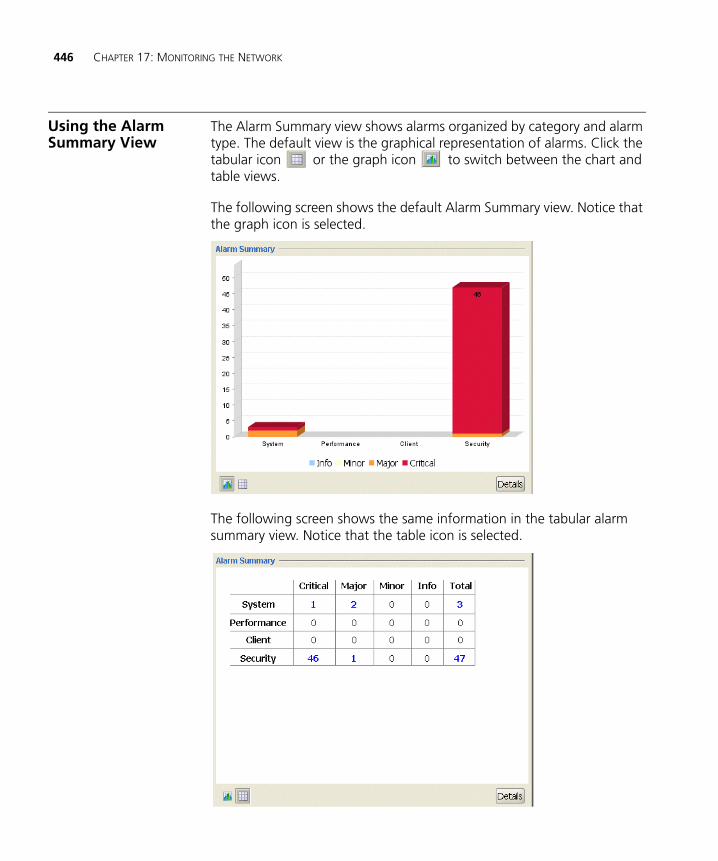
446 CHAPTER 17: MONITORING THE NETWORK
Using the Alarm Summary View
The Alarm Summary view shows alarms organized by category and alarm type. The default view is the graphical representation of alarms. Click the tabular icon or the graph icon to switch between the chart and table views.
The following screen shows the default Alarm Summary view. Notice that the graph icon is selected.
The following screen shows the same information in the tabular alarm summary view. Notice that the table icon is selected.
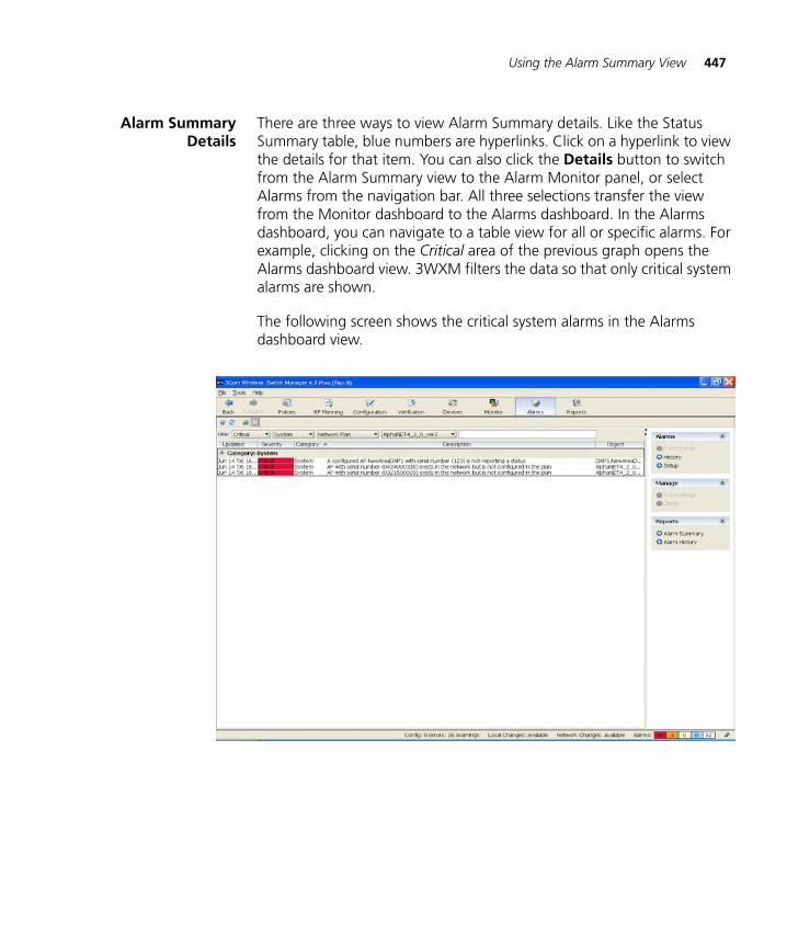
Using the Alarm Summary View 447
Alarm SummaryDetails
There are three ways to view Alarm Summary details. Like the Status Summary table, blue numbers are hyperlinks. Click on a hyperlink to view the details for that item. You can also click the Details button to switch from the Alarm Summary view to the Alarm Monitor panel, or select Alarms from the navigation bar. All three selections transfer the view from the Monitor dashboard to the Alarms dashboard. In the Alarms dashboard, you can navigate to a table view for all or specific alarms. For example, clicking on the Critical area of the previous graph opens the Alarms dashboard view. 3WXM filters the data so that only critical system alarms are shown.
The following screen shows the critical system alarms in the Alarms dashboard view.
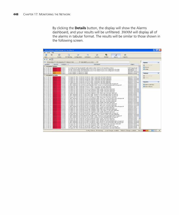
448 CHAPTER 17: MONITORING THE NETWORK
By clicking the Details button, the display will show the Alarms dashboard, and your results will be unfiltered. 3WXM will display all of the alarms in tabular format. The results will be similar to those shown in the following screen.
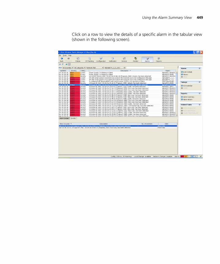
Using the Alarm Summary View 449
Click on a row to view the details of a specific alarm in the tabular view (shown in the following screen).
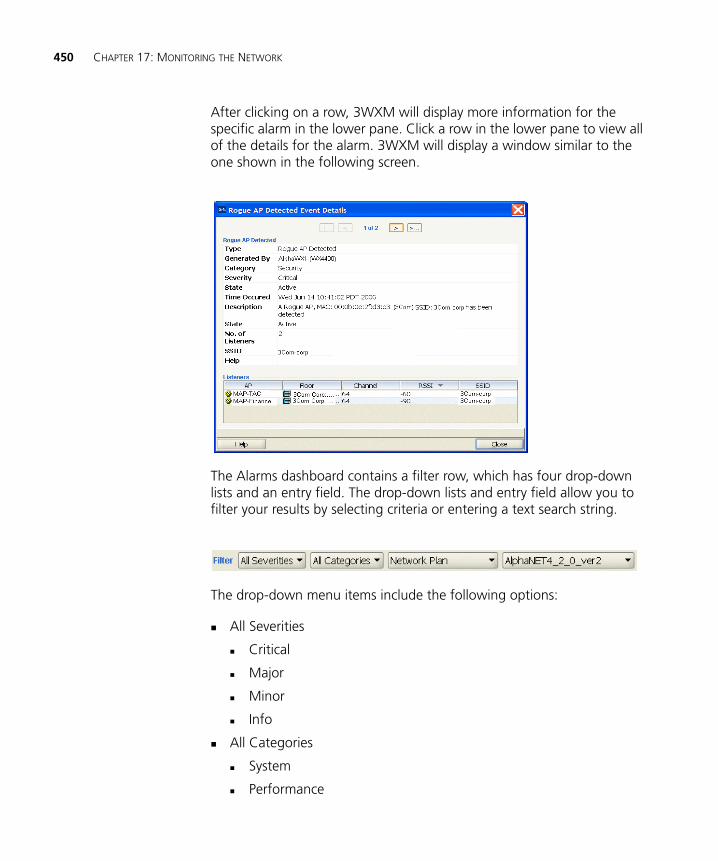
450 CHAPTER 17: MONITORING THE NETWORK
After clicking on a row, 3WXM will display more information for the specific alarm in the lower pane. Click a row in the lower pane to view all of the details for the alarm. 3WXM will display a window similar to the one shown in the following screen.
The Alarms dashboard contains a filter row, which has four drop-down lists and an entry field. The drop-down lists and entry field allow you to filter your results by selecting criteria or entering a text search string.
The drop-down menu items include the following options:
All Severities
Critical
Major
Minor
Info
All Categories
System
Performance
Using the Alarm Summary View 451
Client
Security
Network Plan
Mobility Domain
Mobility Exchange
10/100 Ethernet Port
Gigabit Ethernet Port
Distributed AP
AP
Radio
Site
Building
Floor
Network plan name(s)
These options allow you to see a variety of specific alarms for each device in the network.
Additional AlarmOptions
Additional alarm options are available from the Alarms dashboard. These options are located in the upper right side of the screen and include the following:
Alarms
Event Details
History
Setup
Manage
Acknowledge
Delete
Reports
Alarm Summary
Alarm History
Related Tasks
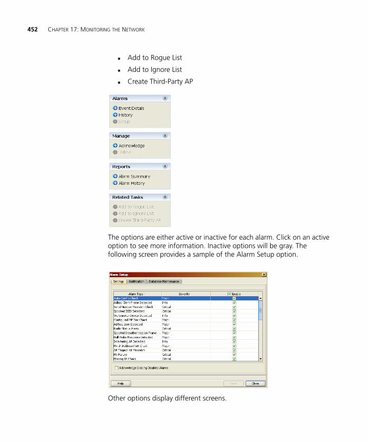
452 CHAPTER 17: MONITORING THE NETWORK
Add to Rogue List
Add to Ignore List
Create Third-Party AP
The options are either active or inactive for each alarm. Click on an active option to see more information. Inactive options will be gray. The following screen provides a sample of the Alarm Setup option.
Other options display different screens.
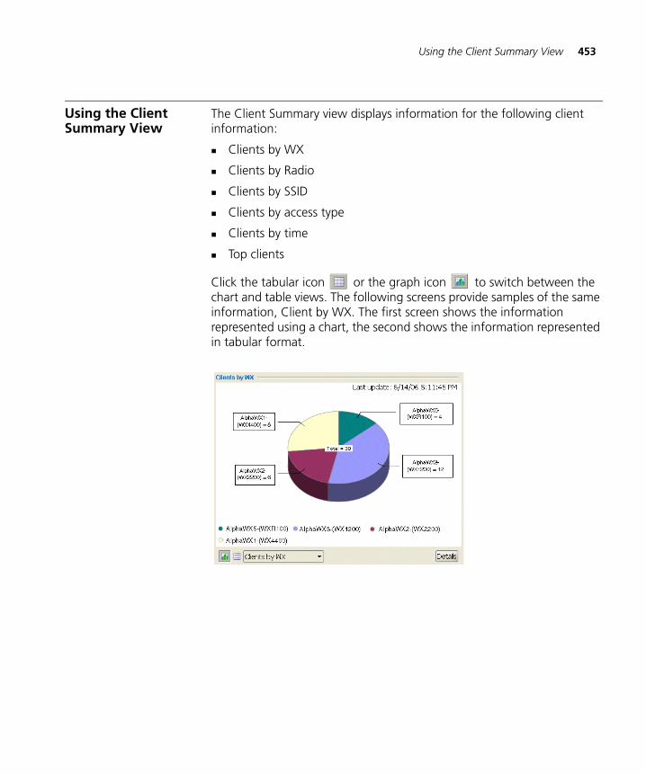
Using the Client Summary View 453
Using the Client Summary View
The Client Summary view displays information for the following client information:
Clients by WX
Clients by Radio
Clients by SSID
Clients by access type
Clients by time
Top clients
Click the tabular icon or the graph icon to switch between the chart and table views. The following screens provide samples of the same information, Client by WX. The first screen shows the information represented using a chart, the second shows the information represented in tabular format.
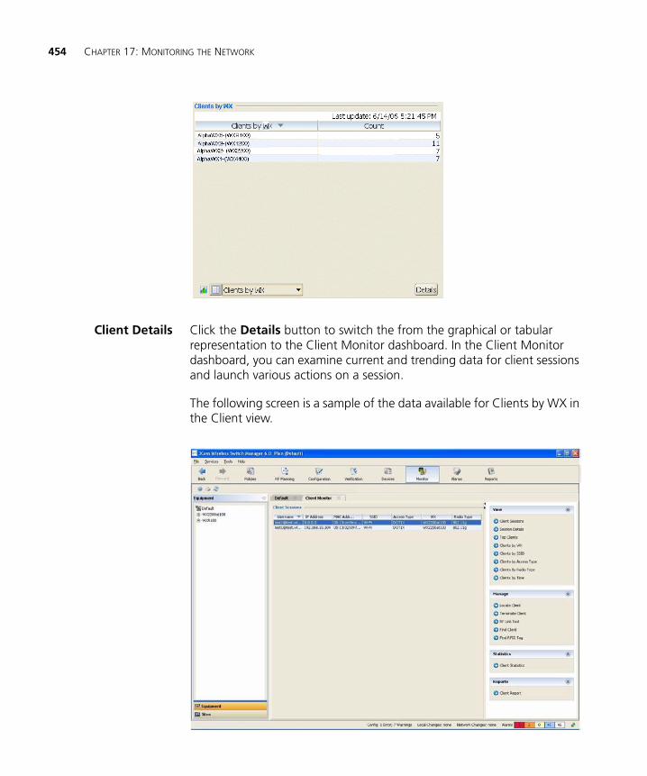
454 CHAPTER 17: MONITORING THE NETWORK
Client Details Click the Details button to switch the from the graphical or tabular representation to the Client Monitor dashboard. In the Client Monitor dashboard, you can examine current and trending data for client sessions and launch various actions on a session.
The following screen is a sample of the data available for Clients by WX in the Client view.
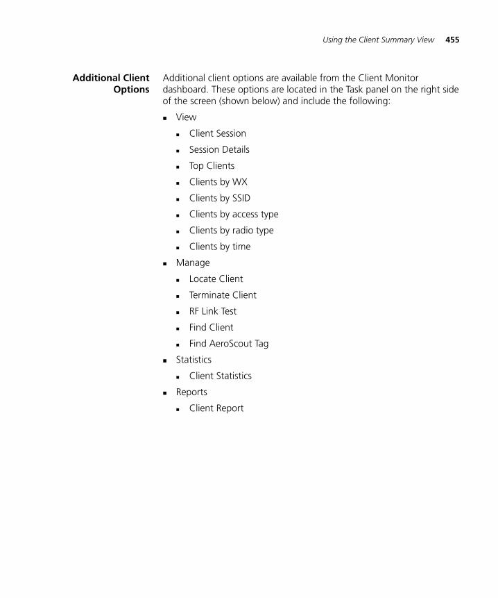
Using the Client Summary View 455
Additional ClientOptions
Additional client options are available from the Client Monitor dashboard. These options are located in the Task panel on the right side of the screen (shown below) and include the following:
View
Client Session
Session Details
Top Clients
Clients by WX
Clients by SSID
Clients by access type
Clients by radio type
Clients by time
Manage
Locate Client
Terminate Client
RF Link Test
Find Client
Find AeroScout Tag
Statistics
Client Statistics
Reports
Client Report
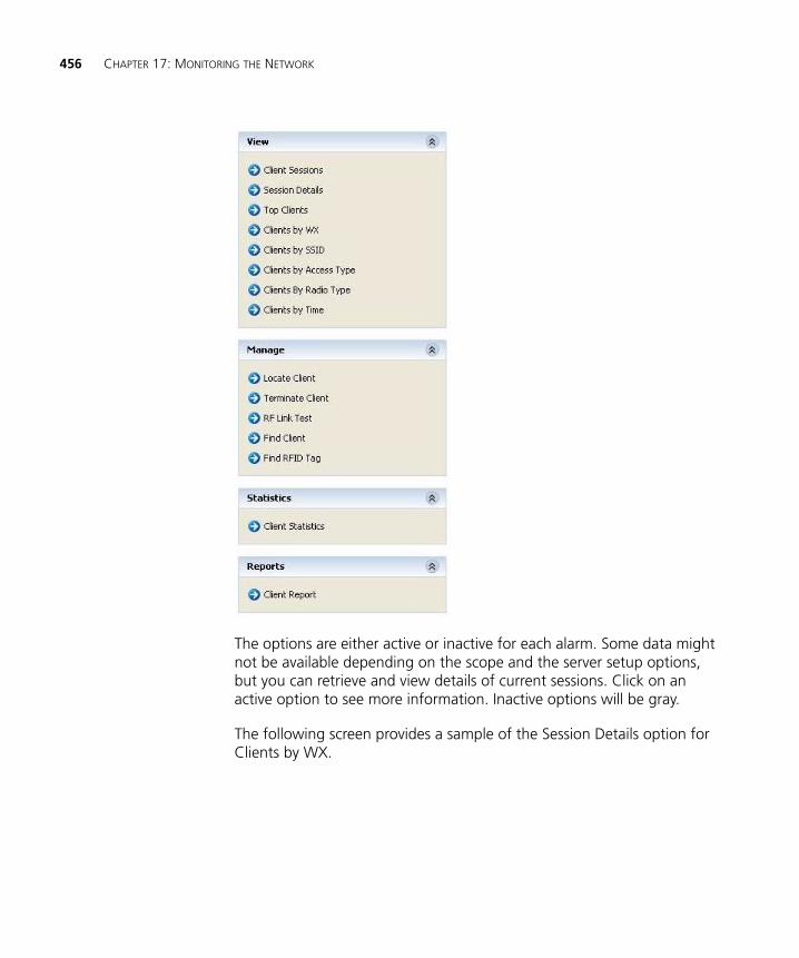
456 CHAPTER 17: MONITORING THE NETWORK
The options are either active or inactive for each alarm. Some data might not be available depending on the scope and the server setup options, but you can retrieve and view details of current sessions. Click on an active option to see more information. Inactive options will be gray.
The following screen provides a sample of the Session Details option for Clients by WX.
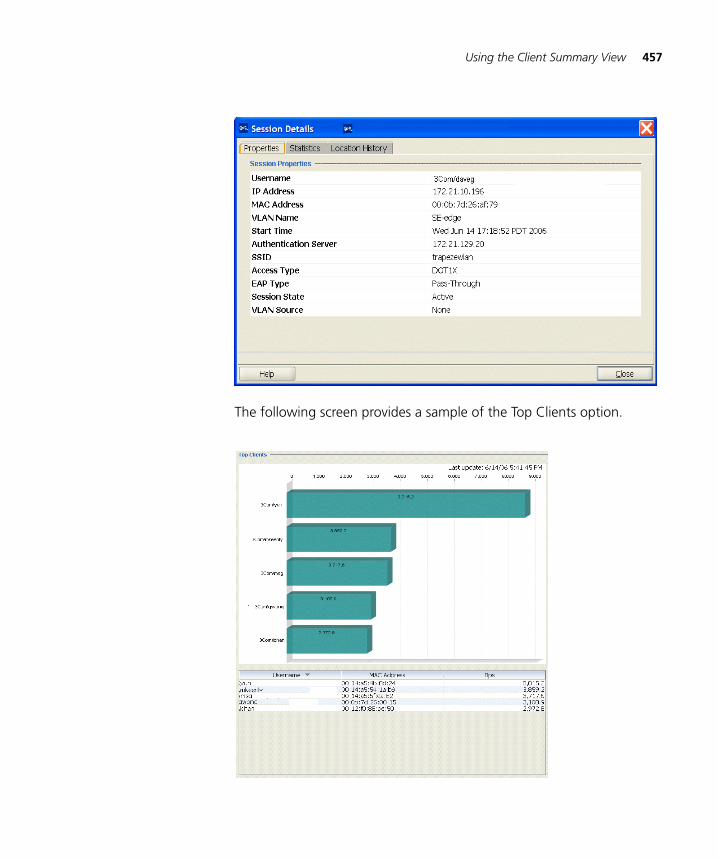
Using the Client Summary View 457
The following screen provides a sample of the Top Clients option.
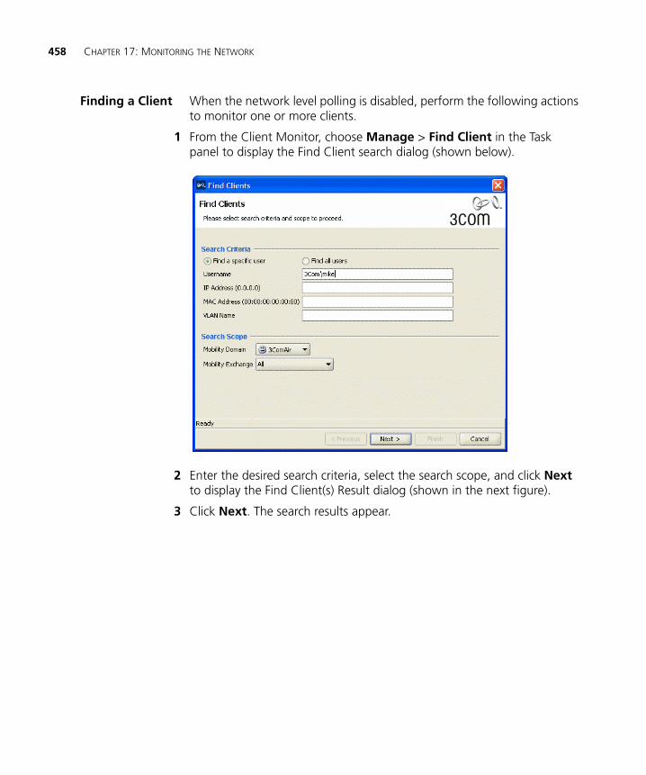
458 CHAPTER 17: MONITORING THE NETWORK
Finding a Client When the network level polling is disabled, perform the following actions to monitor one or more clients.
1 From the Client Monitor, choose Manage > Find Client in the Task panel to display the Find Client search dialog (shown below).
2 Enter the desired search criteria, select the search scope, and click Next to display the Find Client(s) Result dialog (shown in the next figure).
3 Click Next. The search results appear.
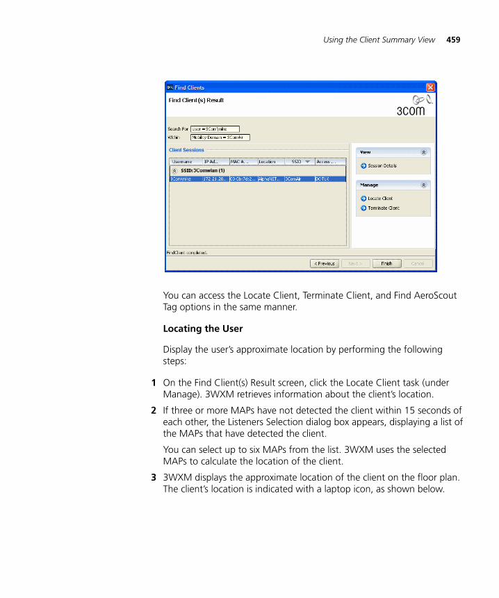
Using the Client Summary View 459
You can access the Locate Client, Terminate Client, and Find AeroScout Tag options in the same manner.
Locating the User
Display the user’s approximate location by performing the following steps:
1 On the Find Client(s) Result screen, click the Locate Client task (under Manage). 3WXM retrieves information about the client’s location.
2 If three or more MAPs have not detected the client within 15 seconds of each other, the Listeners Selection dialog box appears, displaying a list of the MAPs that have detected the client.
You can select up to six MAPs from the list. 3WXM uses the selected MAPs to calculate the location of the client.
3 3WXM displays the approximate location of the client on the floor plan. The client’s location is indicated with a laptop icon, as shown below.
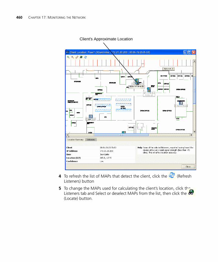
460 CHAPTER 17: MONITORING THE NETWORK
4 To refresh the list of MAPs that detect the client, click the (Refresh Listeners) button
5 To change the MAPs used for calculating the client’s location, click the Listeners tab and Select or deselect MAPs from the list, then click the (Locate) button.
Client’s Approximate Location
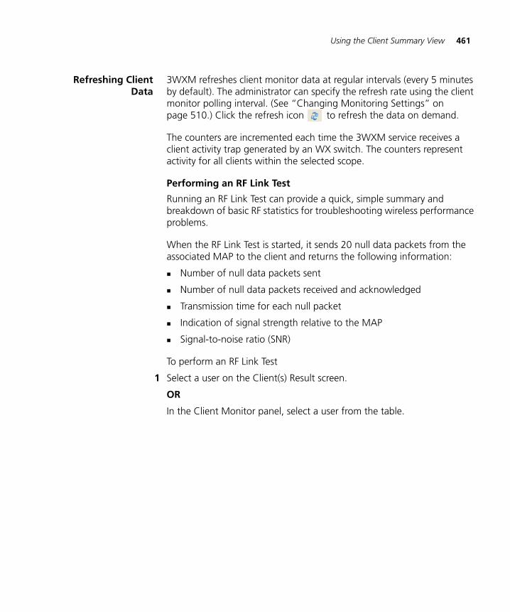
Using the Client Summary View 461
Refreshing ClientData
3WXM refreshes client monitor data at regular intervals (every 5 minutes by default). The administrator can specify the refresh rate using the client monitor polling interval. (See “Changing Monitoring Settings” on page 510.) Click the refresh icon to refresh the data on demand.
The counters are incremented each time the 3WXM service receives a client activity trap generated by an WX switch. The counters represent activity for all clients within the selected scope.
Performing an RF Link Test
Running an RF Link Test can provide a quick, simple summary and breakdown of basic RF statistics for troubleshooting wireless performance problems.
When the RF Link Test is started, it sends 20 null data packets from the associated MAP to the client and returns the following information:
Number of null data packets sent
Number of null data packets received and acknowledged
Transmission time for each null packet
Indication of signal strength relative to the MAP
Signal-to-noise ratio (SNR)
To perform an RF Link Test
1 Select a user on the Client(s) Result screen.
OR
In the Client Monitor panel, select a user from the table.
462 CHAPTER 17: MONITORING THE NETWORK
2 Choose Manage > RF Link Test in the Task panel to run a link test and display the Link Test results dialog, as shown below.
3 Click the Refresh button to perform another link test and repopulate the RF Link Test table with new data.
Using the Traffic Summary View
The Traffic Summary view displays network usage and RF summary data. 3WXM shows both traffic and RF statistics for Radio, AP, Floor, Building, and Site options, but only traffic data is applicable for MS, Mobility Domain, and Network Plan options. Click the tabular icon or the graph icon to switch between the chart and table views.
The following options are available for WX, Mobility Domain, and Network Plan:
1 Hour
24 Hour
7 Days
30 Days
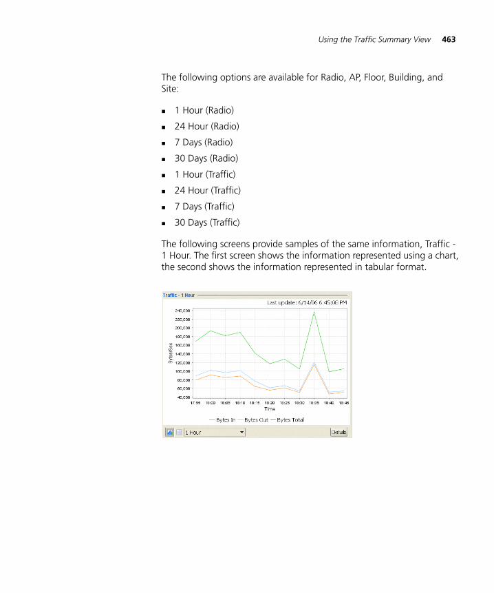
Using the Traffic Summary View 463
The following options are available for Radio, AP, Floor, Building, and Site:
1 Hour (Radio)
24 Hour (Radio)
7 Days (Radio)
30 Days (Radio)
1 Hour (Traffic)
24 Hour (Traffic)
7 Days (Traffic)
30 Days (Traffic)
The following screens provide samples of the same information, Traffic - 1 Hour. The first screen shows the information represented using a chart, the second shows the information represented in tabular format.
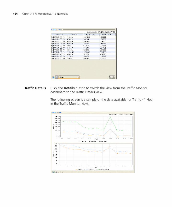
464 CHAPTER 17: MONITORING THE NETWORK
Traffic Details Click the Details button to switch the view from the Traffic Monitor dashboard to the Traffic Details view.
The following screen is a sample of the data available for Traffic - 1 Hour in the Traffic Monitor view.
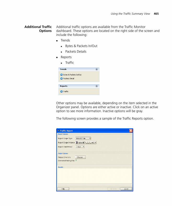
Using the Traffic Summary View 465
Additional TrafficOptions
Additional traffic options are available from the Traffic Monitor dashboard. These options are located on the right side of the screen and include the following:
Trends
Bytes & Packets In/Out
Packets Details
Reports
Traffic
Other options may be available, depending on the item selected in the Organizer panel. Options are either active or inactive. Click on an active option to see more information. Inactive options will be gray.
The following screen provides a sample of the Traffic Reports option.
466 CHAPTER 17: MONITORING THE NETWORK
Voice Monitoring with Traffic Views
3WXM 6.0 now includes monitoring functions which can assist with voice deployments. QoS statistics, including per-queue Tx and Rx counts, can be accessed through the Traffic Monitor dashboard, allowing you to perform real-time monitoring of QoS on a specific radio or a specific client.
Using the Floor View Monitor
Before implementing a wireless network, a floor plan is configured that uses RF Planning and Location. You can select a MAP access point from the Monitoring Equipment tree and display a floor map with that AP selected.
From this view, you can generate visualizations of operational statistics such as RSSI, re-transmits, SNR, and signal level to determine problem areas.
To find an AP on the floor
1 Click on the Monitor option in the main 3WXM tool bar.
2 Expand the Site list tree in the Organizer panel and select the access point you want to view.
3 3WXM automatically opens the Floor View panel, displaying a floor map with the selected access point highlighted.
4 Select a statistic from the Task panel to generate a topographical visualization of that data. (If you choose the RF Interference, High Utilization, or Coverage Hole options and re-transmit rates within the depicted area do not exceed 10% of total network bytes, 3WXM displays a message dialog instead of generating a visualization.)
In the example below, the selected access point is highlighted and RSSI for the coverage area is depicted in the Floor Viewer.
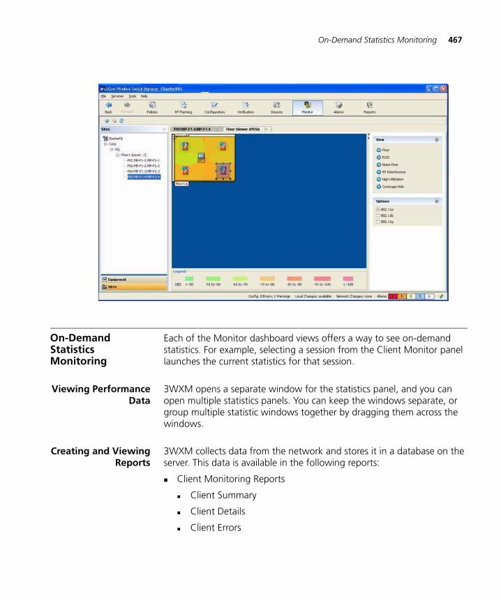
On-Demand Statistics Monitoring 467
On-Demand Statistics Monitoring
Each of the Monitor dashboard views offers a way to see on-demand statistics. For example, selecting a session from the Client Monitor panel launches the current statistics for that session.
Viewing PerformanceData
3WXM opens a separate window for the statistics panel, and you can open multiple statistics panels. You can keep the windows separate, or group multiple statistic windows together by dragging them across the windows.
Creating and ViewingReports
3WXM collects data from the network and stores it in a database on the server. This data is available in the following reports:
Client Monitoring Reports
Client Summary
Client Details
Client Errors
468 CHAPTER 17: MONITORING THE NETWORK
Traffic Reports
Network Usage (Port Traffic)
Network Usage (Radio Traffic)
RF Statistics
RF Summary
Radio Details
Rogue Reports
Rogue Details
Rogue Summary
Alarm Reports
Alarm Summary
Alarm History
Security
Client OUI
RF Planning reports
Site Survey Order
Work Order
For each report, use the wizard to configure the report scope type, report scope instance, and time period settings. Some reports may require additional parameters.
3WXM generates a report and saves it on the server. To view the report, click the report link provided by the wizard. (For more information on 3WXM reports, see “Generating Reports” on page 417.)
18 DETECTING AND COMBATTING ROGUE DEVICES
This chapter discusses how to manage rogue devices that try to use your wireless network. Information includes an overview of detection features, enabling countermeasures, using the Rogue Detection tab, displaying a rogue’s geographical location, ignoring friendly third-party devices, and converting a rogue into a third party AP.
Overview MAP radios automatically scan the RF spectrum for other devices transmitting in the same spectrum. The RF scans discover third-party transmitters in addition to other 3Com radios. MSS considers the third-party transmitters to be devices of interest, which are potential rogues.
You can display information about the devices of interest. To identify friendly devices, such as non-3Com access points in yours or your neighbor’s network, you can add them to the known devices list. You also can enable countermeasures to prevent clients from using the devices that truly are rogues.
With 3WXM, you also can display the physical location of a rogue device.
470 CHAPTER 18: DETECTING AND COMBATTING ROGUE DEVICES
Rogue Detection Requirements
Rogue detection in 3WXM has the following requirements.
The Enable Rogue Detection option must be selected on the Monitoring Settings section of the 3WXM Services Setup dialog. (See “Changing Monitoring Settings” on page 510.)
To use countermeasures, they must be enabled. You can enable them on an individual radio profile basis. (See “Viewing and Configuring Radio Profiles” on page 272.)
SNMP notifications must be enabled on the WX switches. Table 34 lists the notification types related to RF detection. The notification types for Intrusion Detection System (IDS) and Denial of Service (DoS) protection are also listed. (To enable notifications on a switch, see “Configuring SNMP” on page 196.)
Table 34 SNMP Notifications for RF Detection
Notification Type Description
Rogue detection notifications
RogueDetect Indicates that MSS has detected a rogue AP.
RFDetectRougeDisappear Indicates that MSS is no longer detecting a previously detected rogue AP.
RFDetectInterferingRogueAP Indicates that MSS has detected an interfering device.
RFDetectInterferingRogueDisappear Indicates that MSS is no longer detecting a previously detected interfering device.
RFDetectAdHocUser Indicates that MSS has detected an ad-hoc user.
RFDetectUnAuthorizedSSID Indicates that MSS has detected an SSID that is not on the permitted SSID list.
RFDetectUnAuthorizedOUI Indicates that MSS has detected a wireless device that is not on the list of permitted vendors.
RFDetectUnAuthorizedAP Indicates that MSS has detected the MAC address of an AP that is on the attack list.
IDS/DoS notifications
For more information about IDS/DoS, see the “IDS and DoS Alerts” section in the “Rogue Detection and Countermeasures” chapter of the Wireless LAN Switch and Controller Configuration Guide.
CounterMeasureStart Indicates that MSS has begun countermeasures against a rogue AP.
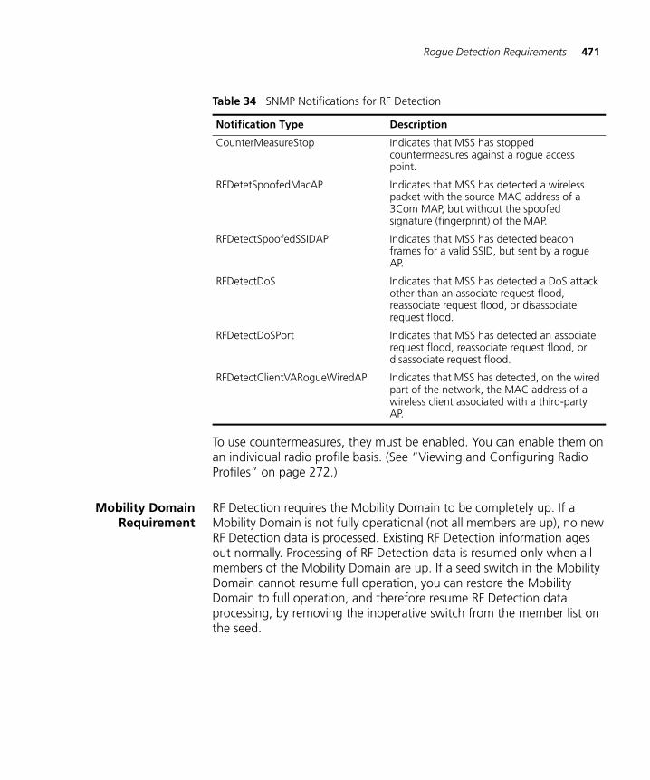
Rogue Detection Requirements 471
To use countermeasures, they must be enabled. You can enable them on an individual radio profile basis. (See “Viewing and Configuring Radio Profiles” on page 272.)
Mobility DomainRequirement
RF Detection requires the Mobility Domain to be completely up. If a Mobility Domain is not fully operational (not all members are up), no new RF Detection data is processed. Existing RF Detection information ages out normally. Processing of RF Detection data is resumed only when all members of the Mobility Domain are up. If a seed switch in the Mobility Domain cannot resume full operation, you can restore the Mobility Domain to full operation, and therefore resume RF Detection data processing, by removing the inoperative switch from the member list on the seed.
CounterMeasureStop Indicates that MSS has stopped countermeasures against a rogue access point.
RFDetetSpoofedMacAP Indicates that MSS has detected a wireless packet with the source MAC address of a 3Com MAP, but without the spoofed signature (fingerprint) of the MAP.
RFDetectSpoofedSSIDAP Indicates that MSS has detected beacon frames for a valid SSID, but sent by a rogue AP.
RFDetectDoS Indicates that MSS has detected a DoS attack other than an associate request flood, reassociate request flood, or disassociate request flood.
RFDetectDoSPort Indicates that MSS has detected an associate request flood, reassociate request flood, or disassociate request flood.
RFDetectClientVARogueWiredAP Indicates that MSS has detected, on the wired part of the network, the MAC address of a wireless client associated with a third-party AP.
Table 34 SNMP Notifications for RF Detection
Notification Type Description
472 CHAPTER 18: DETECTING AND COMBATTING ROGUE DEVICES
Rogue Detection Lists
Rogue detection lists specify the third-party devices and SSIDs that MSS allows on the network, and the devices MSS classifies as rogues. You can configure the following rogue detection lists:
Permitted SSID list—A list of SSIDs allowed in the Mobility Domain. MSS generates a message if an SSID that is not on the list is detected.
Permitted vendor list—A list of the wireless networking equipment vendors whose equipment is allowed on the network. 3WXM identifies the vendor of a piece of equipment by using the Organizationally Unique Identifier (OUI). The OUI is the first three bytes of the MAC address that the equipment uses. MSS generates a message if an AP or wireless client with an OUI that is not on the list is detected.
Rogue list—A list of AP MAC addresses to attack whenever they are present on the network.
Client black list—A list of MAC addresses of wireless clients who are not allowed on the network. MSS prevents clients on the list from accessing the network through a WX switch. If the client is placed on the black list dynamically by MSS due to an association, reassociation or disassociation flood, MSS generates a log message.
Ignore list—A list of third-party devices that you want to exempt from rogue detection. MSS does not count devices on the ignore list as rogues or interfering devices, and does not issue countermeasures against them.
An empty permitted SSID list or permitted vendor list implicitly allows all SSIDs or vendors. However, when you add an entry to the SSID or vendor list, all SSIDs or vendors that are not in the list are implicitly disallowed. An empty client black list implicitly allows all clients, and an empty ignore list implicitly considers all third-party wireless devices to be potential rogues.
All of the lists except the black list require manual configuration. You can configure entries in the black list, and MSS can place a client in the black list due to an association, reassociation, or disassociation flood from the client.
The rogue classification algorithm examines each of these lists when determining whether a device is a rogue. The following figure shows how the rogue detection algorithm uses the lists.
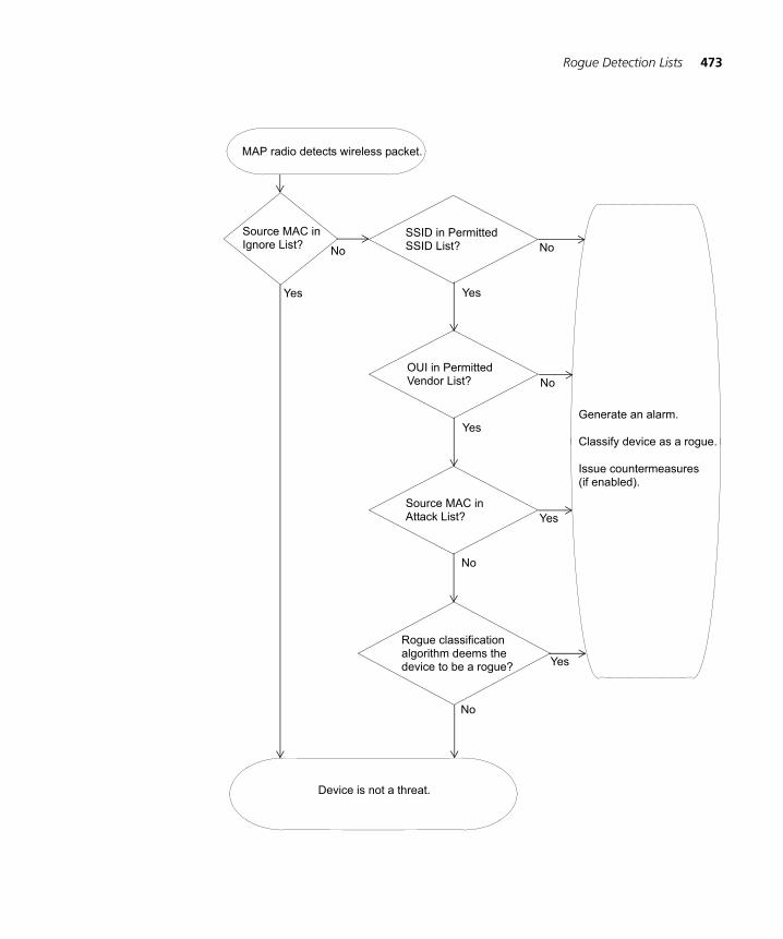
Rogue Detection Lists 473
MAP radio detects wireless packet.
No
Yes Yes
Source MAC in SSID in PermittedIgnore List?
Device is not a threat.
SSID List?
Yes
OUI in PermittedVendor List?
No
Source MAC in Attack List?
No
Generate an alarm.
Classify device as a rogue.
No
Yes
Issue countermeasures(if enabled).
No
Rogue classification
Yesalgorithm deems thedevice to be a rogue?
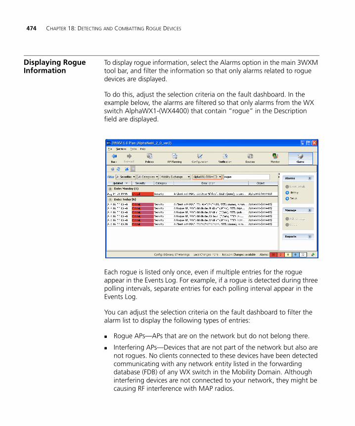
474 CHAPTER 18: DETECTING AND COMBATTING ROGUE DEVICES
Displaying Rogue Information
To display rogue information, select the Alarms option in the main 3WXM tool bar, and filter the information so that only alarms related to rogue devices are displayed.
To do this, adjust the selection criteria on the fault dashboard. In the example below, the alarms are filtered so that only alarms from the WX switch AlphaWX1-(WX4400) that contain “rogue” in the Description field are displayed.
Each rogue is listed only once, even if multiple entries for the rogue appear in the Events Log. For example, if a rogue is detected during three polling intervals, separate entries for each polling interval appear in the Events Log.
You can adjust the selection criteria on the fault dashboard to filter the alarm list to display the following types of entries:
Rogue APs—APs that are on the network but do not belong there.
Interfering APs—Devices that are not part of the network but also are not rogues. No clients connected to these devices have been detected communicating with any network entity listed in the forwarding database (FDB) of any WX switch in the Mobility Domain. Although interfering devices are not connected to your network, they might be causing RF interference with MAP radios.
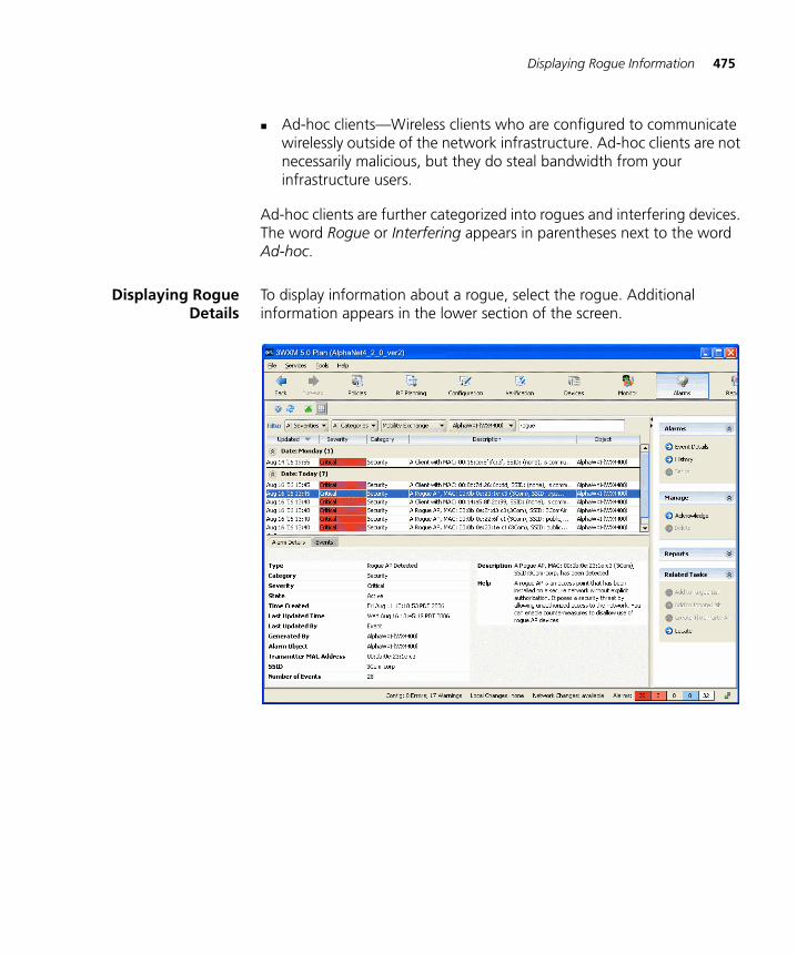
Displaying Rogue Information 475
Ad-hoc clients—Wireless clients who are configured to communicate wirelessly outside of the network infrastructure. Ad-hoc clients are not necessarily malicious, but they do steal bandwidth from your infrastructure users.
Ad-hoc clients are further categorized into rogues and interfering devices. The word Rogue or Interfering appears in parentheses next to the word Ad-hoc.
Displaying RogueDetails
To display information about a rogue, select the rogue. Additional information appears in the lower section of the screen.
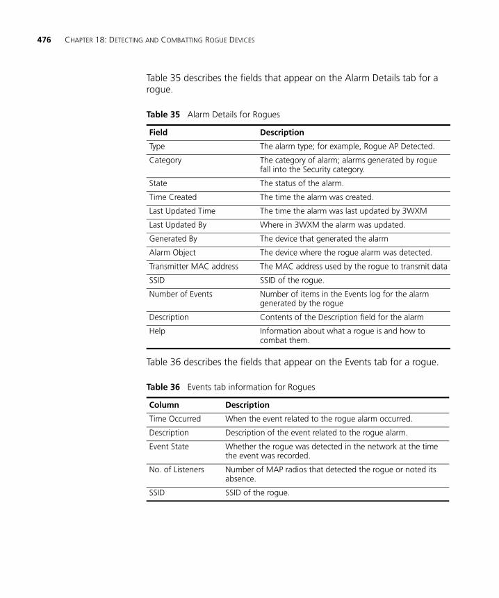
476 CHAPTER 18: DETECTING AND COMBATTING ROGUE DEVICES
Table 35 describes the fields that appear on the Alarm Details tab for a rogue.
Table 36 describes the fields that appear on the Events tab for a rogue.
Table 35 Alarm Details for Rogues
Field Description
Type The alarm type; for example, Rogue AP Detected.
Category The category of alarm; alarms generated by rogue fall into the Security category.
State The status of the alarm.
Time Created The time the alarm was created.
Last Updated Time The time the alarm was last updated by 3WXM
Last Updated By Where in 3WXM the alarm was updated.
Generated By The device that generated the alarm
Alarm Object The device where the rogue alarm was detected.
Transmitter MAC address The MAC address used by the rogue to transmit data
SSID SSID of the rogue.
Number of Events Number of items in the Events log for the alarm generated by the rogue
Description Contents of the Description field for the alarm
Help Information about what a rogue is and how to combat them.
Table 36 Events tab information for Rogues
Column Description
Time Occurred When the event related to the rogue alarm occurred.
Description Description of the event related to the rogue alarm.
Event State Whether the rogue was detected in the network at the time the event was recorded.
No. of Listeners Number of MAP radios that detected the rogue or noted its absence.
SSID SSID of the rogue.
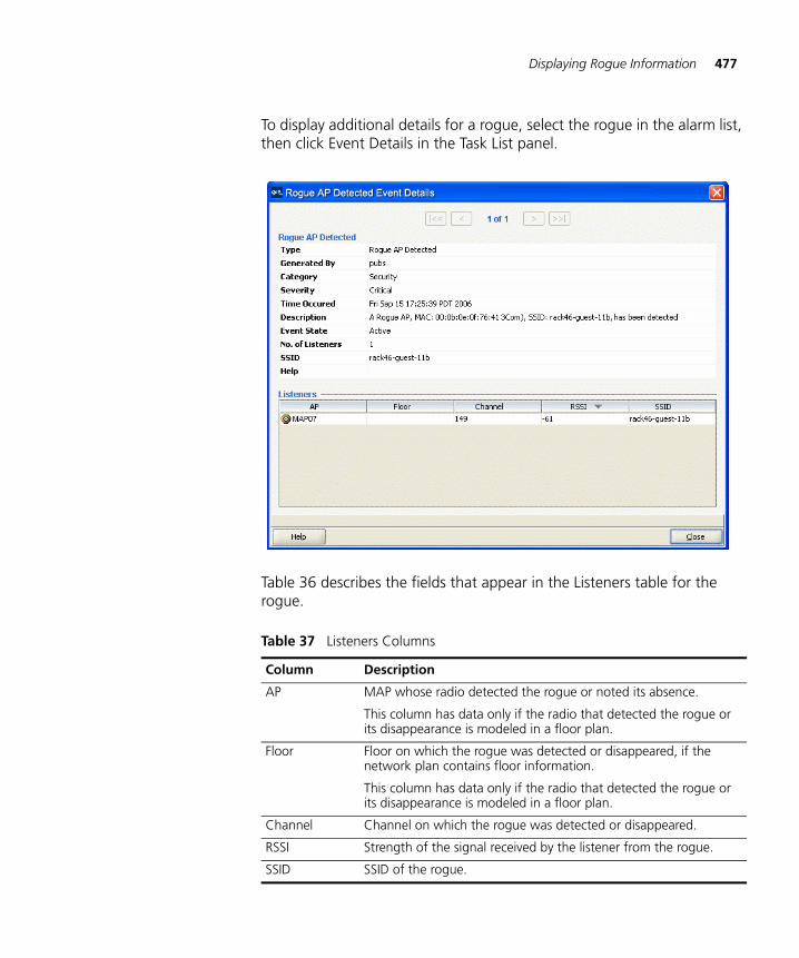
Displaying Rogue Information 477
To display additional details for a rogue, select the rogue in the alarm list, then click Event Details in the Task List panel.
Table 36 describes the fields that appear in the Listeners table for the rogue.
Table 37 Listeners Columns
Column Description
AP MAP whose radio detected the rogue or noted its absence.
This column has data only if the radio that detected the rogue or its disappearance is modeled in a floor plan.
Floor Floor on which the rogue was detected or disappeared, if the network plan contains floor information.
This column has data only if the radio that detected the rogue or its disappearance is modeled in a floor plan.
Channel Channel on which the rogue was detected or disappeared.
RSSI Strength of the signal received by the listener from the rogue.
SSID SSID of the rogue.
478 CHAPTER 18: DETECTING AND COMBATTING ROGUE DEVICES
Displaying Rogue Client Information
To display details about the clients of rogue devices, select the rogue in the alarm list, then click View Clients in the Task List panel.
Table 38 lists the information displayed on about clients of rogue devices.
Displaying Rogue History
To display the alarms that were generated during the during the most-recent 30-day period, click History Task List panel.
Displaying the Geographical Location of a Rogue
If building and floor information for the site is modeled in the network plan, you can display the likely physical location of a rogue. 3WXM displays the floor plan for the floor where the rogue is believed to be located, and displays the areas where the rogue is probably located.
This option displays the likely location of the rogue when the data was collected by the monitoring service from the seed switch and a Mobility Domain. If the rogue has moved since then, the location information will not be current.
To display the location of a rogue within a site
1 Select the rogue in the alarm list.
2 In the Task Panel, under Related Tasks, click Locate.
The Device Location screen appears, indicating the approximate location of the rogue.
Table 38 Clients Columns
Column Description
Client MAC address of the client.
Vendor Manufacturer of the client.
Channel Channel the client is on.
SSID SSID the client is associated with.
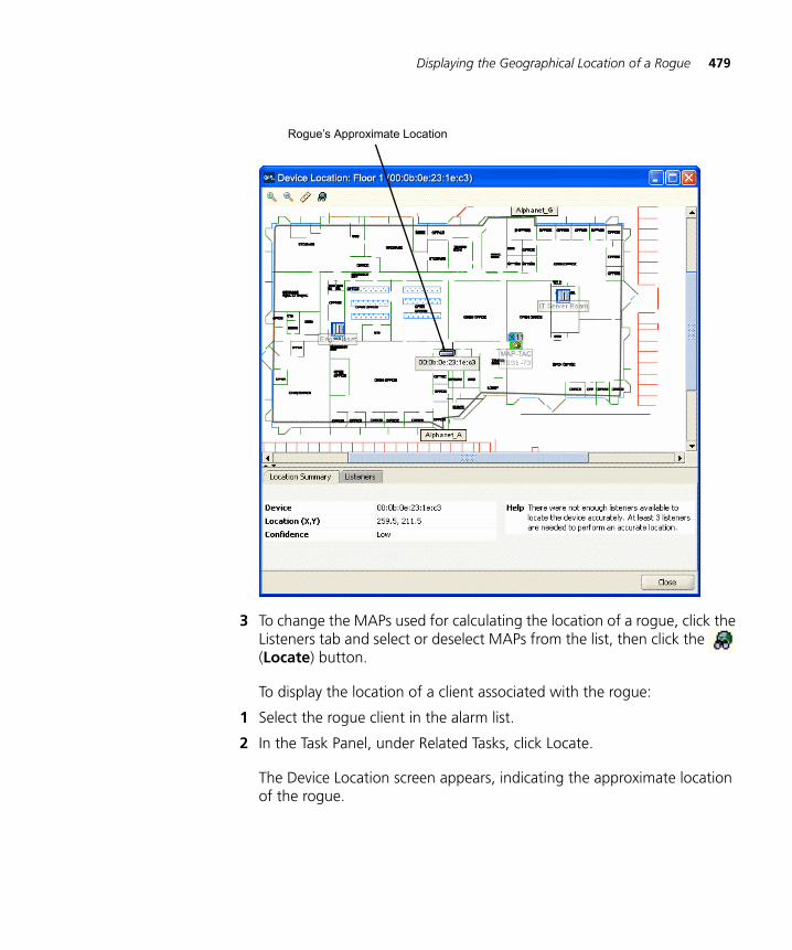
Displaying the Geographical Location of a Rogue 479
3 To change the MAPs used for calculating the location of a rogue, click the Listeners tab and select or deselect MAPs from the list, then click the (Locate) button.
To display the location of a client associated with the rogue:
1 Select the rogue client in the alarm list.
2 In the Task Panel, under Related Tasks, click Locate.
The Device Location screen appears, indicating the approximate location of the rogue.
Rogue’s Approximate Location
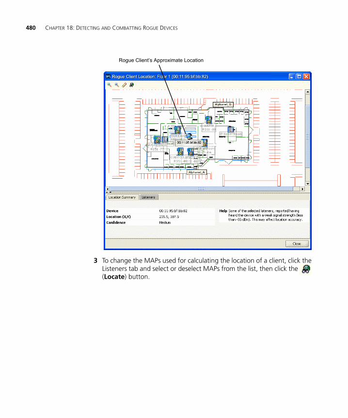
480 CHAPTER 18: DETECTING AND COMBATTING ROGUE DEVICES
3 To change the MAPs used for calculating the location of a client, click the Listeners tab and select or deselect MAPs from the list, then click the (Locate) button.
Rogue Client’s Approximate Location
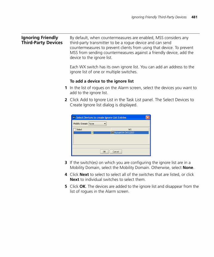
Ignoring Friendly Third-Party Devices 481
Ignoring Friendly Third-Party Devices
By default, when countermeasures are enabled, MSS considers any third-party transmitter to be a rogue device and can send countermeasures to prevent clients from using that device. To prevent MSS from sending countermeasures against a friendly device, add the device to the ignore list.
Each WX switch has its own ignore list. You can add an address to the ignore list of one or multiple switches.
To add a device to the ignore list
1 In the list of rogues on the Alarm screen, select the devices you want to add to the ignore list.
2 Click Add to Ignore List in the Task List panel. The Select Devices to Create Ignore list dialog is displayed.
3 If the switch(es) on which you are configuring the ignore list are in a Mobility Domain, select the Mobility Domain. Otherwise, select None.
4 Click Next to select to select all of the switches that are listed, or click Next to individual switches to select them.
5 Click OK. The devices are added to the ignore list and disappear from the list of rogues in the Alarm screen.
482 CHAPTER 18: DETECTING AND COMBATTING ROGUE DEVICES
Adding a Device to the Rogue List
The rogue list is a list of AP MAC addresses belonging to a switch. 3WXM will attack the AP MAC addresses in the rogue list whenever they are present on the network.
1 In the list of rogues on the Alarm screen, select the devices you want to place on the rogue list.
2 Click Add to Rogue List in the Task List panel. The Select Devices dialog is displayed.
3 If the switch(es) on which you are configuring the rogue list are in a Mobility Domain, select the Mobility Domain. Otherwise, select None.
4 Click Next to select all of the switches that are listed, or click Next to individual switches to select them.
5 Click OK. The devices are added to the rogue list. If countermeasures are enabled, MSS uses them to attack the devices on the list.
Converting a Rogue into a Third Party AP
If a device in the alarm list belongs to a third-party AP in your network, you can convert the rogue into a third-party AP. When you convert a rogue into a third-party AP, the rogue disappears from the alarm list, and allows you to place the AP in your network plan.
Converting a rogue into a third-party AP applies only to the network plan, in 3WXM. 3WXM does not send this information in any form to the WX switches in the network. To prevent MSS from issuing countermeasures against a third-party AP, you must also add the AP to the ignore list. 3WXM does send the ignore list to the WX switches in the network.
To convert a rogueinto a third-party AP
To convert a rogue into a third-party AP, use the following procedure.
1 In the list of rogues on the Alarm screen, select the device you want to convert to a third-party AP.
2 Click Create Third Party AP in the Task List panel. The Third Party AP Properties dialog is displayed.
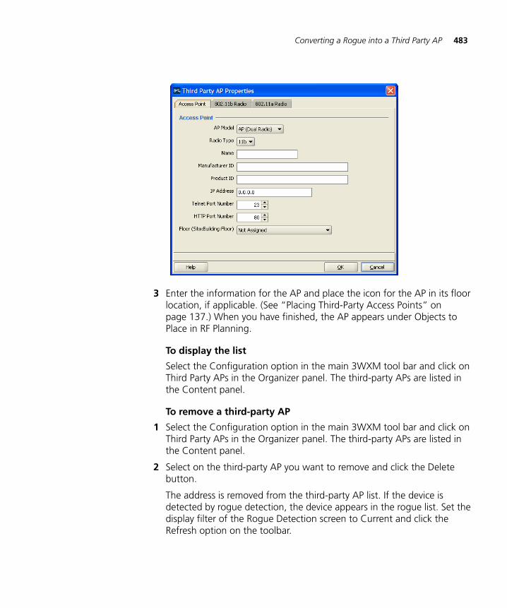
Converting a Rogue into a Third Party AP 483
3 Enter the information for the AP and place the icon for the AP in its floor location, if applicable. (See “Placing Third-Party Access Points” on page 137.) When you have finished, the AP appears under Objects to Place in RF Planning.
To display the list
Select the Configuration option in the main 3WXM tool bar and click on Third Party APs in the Organizer panel. The third-party APs are listed in the Content panel.
To remove a third-party AP
1 Select the Configuration option in the main 3WXM tool bar and click on Third Party APs in the Organizer panel. The third-party APs are listed in the Content panel.
2 Select on the third-party AP you want to remove and click the Delete button.
The address is removed from the third-party AP list. If the device is detected by rogue detection, the device appears in the rogue list. Set the display filter of the Rogue Detection screen to Current and click the Refresh option on the toolbar.
484 CHAPTER 18: DETECTING AND COMBATTING ROGUE DEVICES
Adding Clients Belonging to a Rogue to the Black List
The client black list is a list of MAC addresses belonging to wireless clients who are not allowed on the network. MSS prevents clients on the list from accessing the network through a WX switch.
1 In the Alarm screen, select the client you want to place on the black list.
2 Click Add to Black List on the toolbar. The Select Devices dialog is displayed.
3 Select the clients you want to add to the black list. The Select Devices dialog is displayed.
4 If the switch(es) on which you are configuring the black list are in a Mobility Domain, select the Mobility Domain. Otherwise, select None.
5 Click next to select all of the switches that are listed, or click next to individual switches to select them.
6 Click OK. The selected clients are added to the black list. MSS drops all packets from these clients.
Configuring RF Detection Options from the Organizer Panel
Although the Rogue Detection toolbar options provide the simplest way to configure rogue detection features, you also can configure them on an individual switch basis. To configure rogue detection settings for a switch, see “Viewing and Changing RF Detection Settings” on page 293.
19 OPTIMIZING A NETWORK PLAN
After deploying a network plan to the 3Com equipment in your live network, optimize the plan based on RF information from the network. The RF information can be from a site survey or from MAP radios.
Site survey—RF measurements come from a site survey file generated by the Ekahau Site Survey™ tool. Save the file in comma-separated values (csv) format and import the file into 3WXM.
MAP radios—RF measurements come from the MAPs in the network.
Optimizing your network plan improves the accuracy of the model and provides more precise results when you visualize wireless coverage, locate users and rogue devices, and so on. You also can use optimization to find and fill coverage holes.
Importing RF Measurements
To import RF measurements, you need to import the measurements from MAP radio in the network, from a site survey file, or both. Then, update the RF obstacle data.
Importing theMeasurements
To import the measurements:
1 Select the RF Planning option in the main 3WXM tool bar.
2 Display the floor plan in the Content panel.
3 Under Site Survey, click Import Measurement. The Import RF Measurements wizard is displayed.
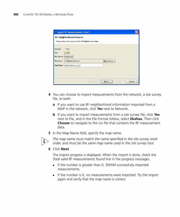
486 CHAPTER 19: OPTIMIZING A NETWORK PLAN
4 You can choose to import measurements from the network, a site survey file, or both:
a If you want to use RF neighborhood information imported from a MAP in the network, click Yes next to Network.
b If you want to import measurements from a site survey file, click Yes next to File, and in the File Format listbox, select Ekahau. Then click Choose to navigate to the csv file that contains the RF measurement data.
5 In the Map Name field, specify the map name.
The map name must match the name specified in the site survey work order, and must be the same map name used in the site survey tool.
6 Click Next.
The import progress is displayed. When the import is done, check the Total valid RF measurements found line in the progress messages.
If the number is greater than 0, 3WXM successfully imported measurements.
If the number is 0, no measurements were imported. Try the import again and verify that the map name is correct.
Importing RF Measurements 487
Applying the RFMeasurements to the
Floor Plan
To apply the RF measurements to the floor plan:
1 Under Site Survey in the Task List panel, click Optimize.
A wizard appears, listing the progress of the request.
The Total number of RF measurements that did not intersect any object line lists the number of measurements that did not experience attenuation due to an RF obstacle in the path between them.
If the measurements came from a site survey file, they are measurements between the portable AP (LOS point) and the PC running the site survey tool. If the measurements came from MAP radios in the network, they are measurements between MAP radios.
The Total number of objects that will be corrected line indicates the number of measurements that did experience attenuation. For existing RF objects, 3WXM corrects the attenuation to match the results.
For RF obstacles created by 3WXM, the description is auto-generated and the obstacle type is Other. You can edit these values by selecting the obstacle, clicking the Edit properties icon to open the Modify RF Obstacle wizard, and modifying the values. Click OK to close the wizard and save the changes. (See “To use the Create RF Obstacle Dialog box” on page 102. The wizard is the same whether it is labeled Create or Modify.)
2 Click Finish.
If the imported RSSI values do not match the values predicated by 3WXM, 3WXM looks for an RF obstacle in the plan that might be causing attenuation, and adjusts its attenuation value in the plan so that the predicted RSSI matches the measured RSSI. However, the following should be noted:
The Optimize feature adjusts attenuation values only if the network plan has an RF obstacle in the line of sight between measurement points (for example, between MAPs that made the measurements). 3WXM does not create an obstacle to account for the RSSI if one does not already exist.
Only one obstacle between any two measurement points is adjusted, even if there are multiple obstacles between the measurement points.
488 CHAPTER 19: OPTIMIZING A NETWORK PLAN
The measurements reflect how well the measuring MAPs can hear one another, and do not directly measure how well clients can hear the MAPs. For example, if the MAPs are mounted on the ceiling, attenuation of their signals to one another might be less than the attenuation of the same signals when received by clients on desktops in cubicles and offices.
Locating and Fixing Coverage Holes
After importing RF measurements and optimizing, look for coverage holes by displaying coverage.
Locating a CoverageHole
To locate a coverage hole:
1 Select the RF Planning option in the main 3WXM tool bar.
2 Display the floor plan in the Content panel.
3 In the Show RF coverage using listbox, select how you want to display the coverage:
Baseline Association Rate—Coverage is shown based on the MAP radio baseline association rate. The baseline association rate is the typical data rate the radio is expected to support for client associations. (The baseline association rate is specified during planning, on a coverage area basis.)
Data Rate—Coverage is shown in colored bands that represent each of the data transmit rates supported by the radio. These rates are standard for each radio type.
RSSI—Coverage is shown based on the received signal strength indication (RSSI) heard by other radios.
4 In the Coverage Areas section of the Organizer panel, select the scope for which you want to display coverage. You can display coverage for an individual radio, a specific coverage area, or all coverage areas on the floor.
To select multiple contiguous objects, click Shift while selecting.
To select multiple noncontiguous objects, click Ctrl while selecting.
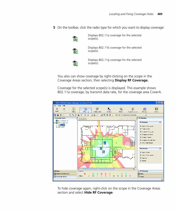
Locating and Fixing Coverage Holes 489
5 On the toolbar, click the radio type for which you want to display coverage:
You also can show coverage by right-clicking on the scope in the Coverage Areas section, then selecting Display RF Coverage.
Coverage for the selected scope(s) is displayed. This example shows 802.11a coverage, by transmit data rate, for the coverage area CoverA.
To hide coverage again, right-click on the scope in the Coverage Areas section and select Hide RF Coverage.
Displays 802.11a coverage for the selected scope(s).
Displays 802.11b coverage for the selected scope(s).
Displays 802.11g coverage for the selected scope(s).
490 CHAPTER 19: OPTIMIZING A NETWORK PLAN
Fixing a CoverageHole
After importing RF measurements, optimizing, and displaying coverage, observe any wireless coverage holes in the network. Use any of the following methods to fix any coverage holes:
Lock the MAPs in place, and use the Compute and Place task to recompute the number of MAPs needed and their recommended placement. If this results in new MAPs being added, install the new MAPs.
Install new MAPs and add them to the network plan. Using this method, you install the new MAP first, then integrate it into your network plan.
Computing andPlacing New MAPs
The procedure for computing and placing new MAPs is the same as the procedure you use for initial planning. Make sure you lock the existing MAPs in place before you compute and place the new MAPs. (See “Computing MAP Placement” on page 143.)
Adding New MAPsthat Are Already
Installed to theNetwork Plan
If you installed a new MAP in the network and you want to add it to the network plan, do the following:
1 Select the Verification option in the main 3WXM tool bar, click the Network Verification tab, and upload the MAP configuration into 3WXM. (See “Verifying Configuration Changes” on page 377.)
2 Select the RF Planning option in the main 3WXM tool bar and display the floor plan in the Content panel.
3 In the Coverage Areas section, right-click on the coverage area for which the MAP is providing coverage, and select Edit Properties. The Coverage Area Properties dialog appears.
4 Click the Associations tab.
5 Select the MAP in the Available Access Points group box and click the Add button to move the MAP to the Current Access Points group box.
6 Click OK to save the changes and close the dialog box.
7 Click on Objects to Place in the Organizer panel.
8 Click on the MAP icon, then click on the location where you installed the MAP. The MAP icon moves from the Objects To Place tab to its location on the floor.
A CHANGING 3WXM PREFERENCES
This chapter discusses how to set 3Com Wireless Switch Manager (3WXM) client preferences. It describes how to reset preferences values and change options for network synchronization, user interface, persistence, tools, certificate management, RF planning, and 3WXM logging.
Overview You can set 3WXM preferences for a user session on the system on which 3WXM is installed. The preferences you set are valid only for that user on that system.
This chapter describes how to change 3WXM Client preferences. To change monitoring service preferences, see “Changing 3WXM Services Preferences” on page 501.
To change 3WXM preferences, in the main 3WXM window, select Tools > Preferences.
Resetting Preferences Values
You can reset the preferences values to their default values by doing one of the following:
To reset the values for a tab, click the tab to display it, and click Reset. (Each tab has a Reset button.)
To reset all preferences for all tabs, click Reset All.
492 CHAPTER A: CHANGING 3WXM PREFERENCES
Changing Network Synchronization Options
By default, 3WXM checks for configuration changes, events, and status changes on WX switches. You can configure checking (also called polling) for configuration changes in the network made with the CLI, Web View, or another instance of 3WXM.
If you do not enable this option, you still can manually synchronize 3WXM with WX switches using the Devices tab. (Select the Devices option from the toolbar in the main 3WXM window. See “Synchronizing Local and Network Changes” on page 365.)
To change network options
1 Select Tools > Preferences. The Preferences dialog box appears.
2 Click the Network tab.
3 To set the amount of time that 3WXM waits for a connection to be established to a WX before trying to connect again, specify the timeout (1 to 30 seconds) in the Connect Timeout box. The default is 5 seconds.
4 To set the number of times (0 to 5) 3WXM tries to reconnect to the WX after the original attempt, specify the value in the Retry Count box. The default is 3 times.
For example, if the retry count is 3, 3WXM attempts to establish a connection to a WX four times. If you specify 0, 3WXM does not attempt to establish a connection if the first attempt is unsuccessful.
5 Click Close to close the Preferences dialog box, or click another tab to continue making changes.
Changing User Interface Options
You can change the following user interface options:
Confirmation prompt when closing wizard pages
Window style for exploring the topological view in the main 3WXM window
Size of icons in 3WXM
Placement of the wizard index in wizard dialog boxes
To change 3WXM user interface options:
1 Select Tools > Preferences. The Preferences dialog box appears.
2 Click the UI tab.
Changing Tools Options 493
3 To enable a confirmation prompt after closing a wizard, select the Warn checkbox.
To disable the confirmation prompt, clear the Warn checkbox. By default, if you close a wizard, a pop-up box appears, asking whether you want to close the wizard. (Changes are lost if you close the wizard.)
If you click Cancel to close a wizard, you do not get a confirmation prompt. If you make changes in a wizard and click Cancel, all changes are lost. To save changes in a wizard, click Finish.
4 Within Window Style, select one of the following:
Single — Show the view in one window when you explore the topology in the main 3WXM window. This is the default setting.
Multiple — Show the topology in multiple windows.
5 Within Icon Size, select one of the following:
16x16 — Change all icons to 16x16 pixels. This is the default setting.
20x20 — Change all icons to 20x20 pixels.
24x24 — Change all icons to 24x24 pixels.
6 Within Show Wizard Index, select one of the following:
On Top — See the wizard index at the top of wizard dialog boxes. This is the default setting.
On Left — See the wizard index on the left of wizard dialog boxes.
7 Click Close to close the Preferences dialog box, or click another tab to continue making changes.
Changing Tools Options
You can change the Telnet and Web browser applications that start from the 3WXM Tools menu. The default Telnet application is Microsoft Telnet Client. The default Web browser is Microsoft Internet Explorer.
To change tools options:
1 Select Tools > Preferences. The Preferences dialog box appears.
2 Click the Tools tab.
3 To change the Telnet executable file or location used by 3WXM, type the path of the executable file in the Telnet Executable box.
494 CHAPTER A: CHANGING 3WXM PREFERENCES
For Windows systems, the default Telnet executable file is C:\WINDOWS\system32\telnet.exe. For Linux systems, the default is /usr/bin/telnet.
You can also click Browse to navigate the computer filesystem.
4 To change the Web browser executable file or location used by 3WXM, type the path of the executable file in the Browser Executable box.
For Windows systems, the default Web browser executable file is C:\Program Files\Internet Explorer\iexplore.exe. For Linux systems, the default is /usr/bin/mozilla.
You can also click Browse to navigate the computer filesystem.
5 Click Close to close the Preferences dialog box, or click another tab to continue making changes.
Changing Certificate Management Options
By default, 3WXM does not accept self-signed certificates from WX switches or from the monitoring service. You can change this option in the Preferences dialog box. (For more information about certificate handling, see “Managing Certificates” on page 383 and “Certificate Check” on page 506.)
To change certificate management options:
1 Select Tools > Preferences. The Preferences dialog box appears.
2 Click the Certificate Handling tab.
3 To automatically accept self-signed certificates, select Always accept self-signed certificates.
To clear this option, clear Always accept self-signed certificates. By default, this option is disabled. The 3WXM Client accepts a certificate only if the certificate is signed by a certificate authority (CA).
4 Click Close to close the Preferences dialog box, or click another tab to continue making changes.
Changing Options for RF Planning 495
Changing Options for RF Planning
You can change the following RF planning options:
Typical transmit power for clients in the 3Com network.
Color schemes for showing RF information
Configuring theTransmit Power of a
Typical Client
To change the transmit power of a typical client:
1 Select Tools > Preferences. The Preferences dialog box appears.
2 Click the RF tab.
3 In the Typical Client Tx Power box, specify the typical transmit power (1 to 20 dBm) for clients in the network. The default is 13 dBm, which is a common client transmit power.
If you want to choose the color for an RF technology or obstacle, see “Changing Colors”.
Changing Colors You can change the color schemes for showing the following types of RF information:
802.11a channels
802.11b and 802.11g channels
RF obstacles
Radio transmit data rates
Receive signal strength (RSSI)
Signal-to-noise ratio (SNR)
Client load (number of clients associated with a radio)
Probability of a rogue device or client being in a specific location
For each scheme, you can change a color using any of the following methods:
Select a color from a predefined palette.
Change the hue, saturation, and brightness (HSB) properties of a color.
Change the red, blue, and green (RGB) properties of a color.
496 CHAPTER A: CHANGING 3WXM PREFERENCES
To Change a Color
1 Select Tools > Preferences. The Preferences dialog box appears.
2 Click the RF tab.
3 Select one of the following tabs:
802.11a Channel Colors
802.11b/g Channel Colors
RF Obstacle Colors
Data Rate Colors
RSSI Band Colors
SNR Band Colors
Load Band Colors
Probability Colors
4 Click on the color column for the color you want to change. The Choose Color dialog box appears.
See one of the following sections:
For more information about using the color palette, see “Defining a Color from the Palette” on page 496.
For more information about using HSB, see “Defining a Color by Changing HSB Properties” on page 497.
For more information about using RGB, see “Defining a Color by Changing RGB Properties” on page 498.
Defining a Color from the Palette
1 To specify a color using the color palette, click Swatches in the Choose Color dialog box.
2 From the color palette, click the color you want to see. Repeat until you find the color you want.
In the Preview box, you can see the swatches and text in the color you chose.
The Recent box shows the colors you have chosen so far. Click Reset to choose the original predefined color and clear the Recent box.
3 Click OK to accept the color you last chose. The RF tab in the Preferences dialog box is active.
Changing Options for RF Planning 497
4 Do one of the following:
Change another color.
Click another Preferences tab.
Click Close to close the Preferences dialog box.
Defining a Color by Changing HSB Properties
You can define colors by changing the hue, saturation, and brightness (HSB).
Hue is the color itself (for example, blue, orange, or purple). Hue is measured in degrees (0 to 360 degrees).
Saturation is the strength of the color. Saturation values are measured in percentages, with 0 percent indicating no color saturation (gray) and 100 percent indicating full saturation.
Brightness is the amount of light in the color. Brightness is also measured in percentages, with 0 percent indicating black and 100 percent indicating white.
To define a color by changing HSB:
1 To specify a color by changing HSB, click HSB in the Choose Color dialog box.
2 To change the hue value, select the H option and do one of the following.
In the H box, specify a value between 0 and 360 degrees.
Use the slider to specify the hue value.
The color appears in the Preview box. You can also see the RGB equivalent in the R, G, and B boxes next to the slider.
3 To change the saturation value, select the S option and do one of the following:
In the S box, specify a value between 0 and 100 percent.
Use the slider to specify the saturation value.
4 To change the brightness value, select the B option and do one of the following:
In the B box, specify a value between 0 and 100 percent.
Use the slider to specify the brightness value.
498 CHAPTER A: CHANGING 3WXM PREFERENCES
5 Click OK to accept the color. The RF Planning Options tab in the Preferences dialog box is active.
6 Do one of the following:
Change another color.
Click another Preferences tab.
Click Close to close the Preferences dialog box.
Defining a Color by Changing RGB Properties
You can define a color by changing red, blue, and green (RGB) color properties.
1 To specify a color by changing RGB, click RGB in the Choose Color dialog box.
2 Use the Red, Green, and Blue sliders to define a color.
You can see a preview of the color in the Preview box.
3 Click OK to accept the color. The RF Planning Options tab in the Preferences dialog box is active.
4 Do one of the following:
Change another color.
Click another Preferences tab.
Click Close to close the Preferences dialog box.
Changing 3WXM Logging Options 499
Changing 3WXM Logging Options
You can change the severity and type of 3WXM events that are logged. By default, the event logging level is set to Critical, and all events are logged.
These log settings apply to log messages generated by 3WXM. They do not apply to log messages generated by WX switches.
To change 3WXM logging options:
1 Select Tools > Preferences. The Preferences dialog box appears.
2 Click the Logging tab.
3 In the Log Event Level list, select one of the following event levels:
Critical — A critical condition has occurred that requires immediate resolution.
Warning — An event that might require attention has occurred.
Info — Informational messages only. No action is required.
Debug — All events are shown, including debug messages.
Select the Debug option only if 3Com Technical Support has advised you to do so. Debug-level logging significantly impacts network performance and should only be enabled temporarily to troubleshoot problems, as directed by Technical Support.
4 Select one or more of the available event types for 3WXM to log.
5 Click Close to close the Preferences dialog box, or click another tab to continue making changes.

500 CHAPTER A: CHANGING 3WXM PREFERENCES
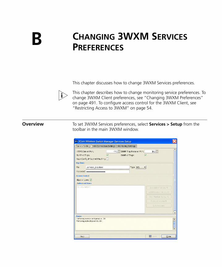
B CHANGING 3WXM SERVICES PREFERENCES
This chapter discusses how to change 3WXM Services preferences.
This chapter describes how to change monitoring service preferences. To change 3WXM Client preferences, see “Changing 3WXM Preferences” on page 491. To configure access control for the 3WXM Client, see “Restricting Access to 3WXM” on page 54.
Overview To set 3WXM Services preferences, select Services > Setup from the toolbar in the main 3WXM window.
502 CHAPTER B: CHANGING 3WXM SERVICES PREFERENCES
A page is opened in your web browser, displaying the 3WXM Services Setup page. When you click Save to implement changes you make on a 3WXM Services page, 3WXM Services verifies the changes. If the changes are valid, the service implements the changes. Otherwise, the service displays error messages and does not implement the changes.
Starting or Stopping the 3WXM Services
The method for starting and stopping monitoring service depends on the platform on which the service is installed:
Windows systems—3WXM Services are started automatically when you complete installation and starts automatically whenever you restart your system.
Linux systems—You can start and stop the service manually from the command line using a shell script that is installed when you install 3WXM Services. You also can configure the service to start and stop automatically.
3Com recommends that all clients that are using 3WXM Services be closed before you stop the services. If a 3WXM Client is using a network plan on 3WXM Services when you stop the services, you cannot select objects or options in the client. In this case, to close the client, click the X in the upper right corner of the window or use Task Manager to end the client session.
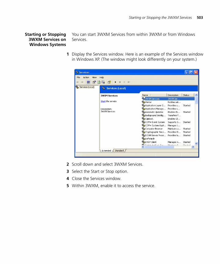
Starting or Stopping the 3WXM Services 503
Starting or Stopping3WXM Services onWindows Systems
You can start 3WXM Services from within 3WXM or from Windows Services.
1 Display the Services window. Here is an example of the Services window in Windows XP. (The window might look differently on your system.)
2 Scroll down and select 3WXM Services.
3 Select the Start or Stop option.
4 Close the Services window.
5 Within 3WXM, enable it to access the service.
504 CHAPTER B: CHANGING 3WXM SERVICES PREFERENCES
Starting or Stopping3WXM Services on
Linux Systems
You can start or stop the service by configuring the service as a daemon.
After 3WXM Services is started, you must enable the 3WXM Client to access the service. (See “Connecting to 3WXM Services”.)
Configuring the Service as a Daemon
The following examples show methods you can use to configure 3WXM Services to automatically start and stop. Other methods might also work. These are the ones that 3Com has tested.
Linux Example—SUSE 9.1 The recommended way to add services to a SUSE 9.1 installation is with the insserv command. Enter commands such as the following (as root):
suse# cd /etc/init.dsuse# ln -s /opt/3wxm/bin/3wxm-services 3wxm-servicessuse# insserv 3wxm-services
Linux Example—Red Hat WS 3 The recommended way to add services to a Red Hat WS 3 system is with the chkconfig command. Enter commands such as the following (as root):
redhat# cd /etc/init.dredhat# ln -s /opt/3wxm/bin/3wxm-services 3wxm-servicesredhat# chkconfig --add 3wxm-services
Connecting to 3WXM Services
If a firewall is enabled on the host where you install 3WXM Services, 3WXM Services will not be able to communicate with 3WXM Client or with WX switches unless the firewall is configured to allow through traffic for the SSL and SNMP ports (443 and 162 by default).
To connect to 3WXM Services
1 Start 3WXM Client.
On Windows systems, select Start > Programs > 3Com Networks > 3WXM > 3WXM, or double-click the 3WXM icon on the desktop.
On Linux systems, change directories to 3WXM_installation_directory/bin, and enter ./3WXM.
Connecting to 3WXM Services 505
The 3WXM Services Connection dialog appears.
2 Enter the IP address or fully-qualified hostname of the machine on which the service is installed.
If the service is installed on the same machine as the one you are using to run 3WXM, enter 127.0.0.1 as the IP address. This is a standard IP loopback address.
3 Specify the service port, if different from the port number in the Service Port listbox.
The port number used by 3WXM Services must not be used by another application on the machine where 3WXM Services is installed. If the port number is used by another application, change the port number on 3WXM Services. (See “Changing Service Settings” on page 508.)
4 Enter a username and password, if required for access to the service.
Usernames and passwords for accessing 3WXM Services are configured on the Service Settings tab. (See “Changing Service Settings” on page 508.)
5 To configure 3WXM Client to remember the username and password for 3WXM Services access, select Remember user name and password.
6 To automatically reopen the network plan that you worked with most recently, leave Open Network Plan selected.
If the Open Network Plan option is selected and this is the first time you are accessing the server from this client, 3WXM Services opens a new (blank) network plan.
7 Click Next.
If the Certificate Check dialog is displayed, click Accept. (For more certificate options, see the next section, “Certificate Check”.)
If the Finish button does not become available, read the last message in the message area of the page to determine why the service could not be reached. Here are common error messages and suggestions for troubleshooting them:
Unable to connect to address: ip-addr:tcp-port-number
Verify that the service is running on the server.
Connection error for address: ip-addr:tcp-port-number
506 CHAPTER B: CHANGING 3WXM SERVICES PREFERENCES
Verify that the service has been started. If the service is running, verify that the certificate on the server is still valid (for example, is not out of date).
HTTP 403: Forbidden
This message can indicate that the username and password are invalid. Ask the administrator for a username and password.
If a license message appears, go to “Starting 3WXM” on page 49.
Certificate Check When the 3WXM Client connects to 3WXM Services, the client checks the certificate presented by 3WXM Services to ensure that the certificate is valid. The certificate is in a key store file on the server.
The default key store file is .services_keystore. This file contains a self-signed certificate for 3WXM Services. You can use this certificate if desired or you can configure the service to use a different key store file containing a different certificate. (See “Changing Service Settings” on page 508.)
By default, the 3WXM Client does not accept self-signed certificates, even from 3WXM Services. Instead, when 3WXM Services or another device presents a self-signed certificate to the 3WXM Client, the Certificate Check dialog box appears on the client. This dialog box displays the certificate information.
The options you select in this dialog box apply to all HTTPS connections with the 3WXM Client. For example, the 3WXM Client also checks the validity of certificates presented by WX switches, and the settings you select in this dialog affect those connections too.
To complete the connection
1 Select one or both of the following options, within 60 seconds after the Certificate Check dialog is displayed:
Always accept self-signed certificates. — Use this option to configure the 3WXM Client to always accept a self-signed certificate from the 3WXM monitoring service and from WX switches.
Install this certificate to validate future connections. — Use this option to accept the certificate and consider the certificate to be valid for future connections.
Verifying that the 3WXM Client is Receiving Service Data 507
When you use this option, the Certificate Check dialog box is not shown again for the certificate, even if the certificate becomes out of date.
2 Click Accept.
To reject the certificate and refuse the connection, click Reject. The 3WXM ends the connection.
The Certificate Check dialog box is redisplayed each time the 3WXM Client attempts to establish a connection with 3WXM Services.
Verifying that the 3WXM Client is Receiving Service Data
If you are using a network plan that already contains equipment, use the following procedure to verify that the 3WXM Client is receiving data for the equipment.
1 Select the network plan name in the Organizer panel.
2 Select the Monitor tool bar option. The monitor dashboard appears.
3 Wait 60 seconds for 3WXM to retrieve updates from the server.
4 Click Details under Status Summary.
5 Check the status colors of the equipment:
Green—Up
Yellow—Up (but with minor service degradation)
Orange—Up (but with major service degradation)
Red—Down
Blue—Unknown (3WXM is not receiving status data from the server yet.)
508 CHAPTER B: CHANGING 3WXM SERVICES PREFERENCES
Changing Service Settings
The service settings control the connection parameters, key store information, and access control to 3WXM Services.
The port numbers used by 3WXM Services must not be used by other applications on the machine where the 3WXM Services is installed. If port 443 or 162 is used by another application, change the port number for the monitoring service or for the other application.
To change service settings
1 Select Services > Setup. A browser window opens, displaying the 3WXM Services Setup page. (See Figure on page 501.)
2 To change the TCP port on which the 3WXM Services listens for requests from 3WXM, type or select the port number in the HTTPS Server Port box. The default is 443.
CAUTION: When you click Save, all instances of the 3WXM Client lose connection with the service and will need to reconnect on the new port number. The HTTPS port number is automatically updated for the 3WXM Client you are using and your connection is automatically restored. Other clients will need to use the Monitor Service Select wizard to change the service port and reconnect.
3 The change the UDP port on which 3WXM Services listens for SNMP traps, type or select the port number in the Trap Receiver Port box. The default is 162.
4 To enable 3WXM Services to receive traps, select one or both of the following trap types:
SNMP V1 Traps
SNMP V3 Traps
You also must add 3WXM Services as a notification target on each WX switch. 3WXM Services does not start listening for SNMP notifications from a WX switch until you add 3WXM Services as an SNMP notification target to the switch. (To configure 3WXM Services as a notification target for a switch, see “Configuring a Notification Target” on page 200).
5 To change the name of the key store file that contains the encryption keys the 3WXM Services uses for authentication with 3WXM, edit the name in the File box. The default name is .services_keystore.
Changing WX Connection Settings 509
6 To change the password that protects access to the key store file, edit the value in the Password box.
7 To specify the file type for the key store file, select one of the following:
PKCS12 — Public-Key Cryptography Standard number 12, the standard format used by Unix machines.
JKS — Java Key Store, a format used by Java platforms and applications.
8 To restrict access to 3WXM Services to specific users “Restricting Access to 3WXM” on page 54.
Changing WX Connection Settings
The WX connection settings control the timeout and retries for connections with monitored WX switches, and the types of certificates the service will accept from the WX switches.
1 Select Services > Setup or select the browser window if 3WXM Services is already open. (See Figure on page 501.)
2 Select Setup, then select WX Connection Settings.
3 To change the number of seconds 3WXM Services waits for a TCP connection with a WX switch to reach the Connect stage, type or select the value in the Connect Timeout box. You can specify from 1 to 30 seconds. The default is 15 seconds.
4 To change the number of times 3WXM Services will reattempt to query a WX switch, if 3WXM Services does not receive a reply to the first query attempt within the connect timeout, type or select the value in the Retry Count box. You can specify from 0 to 5 retries. The default is 5 retries.
5 To prevent 3WXM Services from accepting all types of certificates from the WX switches it monitors, click Accept all certificates to disable the option.
By default, 3WXM Services accepts certificates from WX switches regardless of whether they are generated by a certificate authority (CA) or they are self-signed certificates. When you disable this option, the Accept self-signed certificates option remains enabled.
6 To prevent 3WXM Services from accepting self-signed certificates from the WX switches it monitors, click Accept self-signed certificates to disable the option.
510 CHAPTER B: CHANGING 3WXM SERVICES PREFERENCES
When both the Accept all certificates and Accept self-signed certificates options are disabled, 3WXM Services accepts only-CA generated certificates.
7 To specify a key store filename and a password to protect access to that file:
a Enter the filename in the File box.
b To change the file type for the key store file, select one of the following:
PKCS12 — Public-Key Cryptography Standard number 12, the standard format used by Unix machines.
JKS — Java Key Store, a format used by Java platforms and applications.
c Enter the password in the Password box.
When both the Accept all certificates and Accept self-signed certificates options are disabled, and you specify a key store file, the 3WXM Services accepts a certificate from a WX switch only if the public key information for that certificate is in the key store file.
8 Click Save to save the changes or Cancel to cancel the changes.
Changing Monitoring Settings
By default, status monitoring and monitoring of WX notifications is enabled. Status monitoring supplies data for the Explore and Status Summary windows of the Monitor tab. SNMP notifications (traps) generated by WX switches supply data for the Client Monitor, RF Monitor, and RF Trends windows. Table 39 lists the source of the data for each window in the Monitor tab and for the Performance Statistics window.
Table 39 Sources of Monitor Data
3WXM Client Display Data Source Default
Event log 3WXM Client, for 3WXM Client messages Enabled
3WXM Services, for monitoring service messages
Enabled
Enable Log Monitoring option, for WX switch messages
Enabled
Monitor tab — Status Summary
Status monitoring of WX switches by 3WXM Services
Enabled
Changing Monitoring Settings 511
The monitoring options require SNMP traps to be enabled on the monitored WX switches and also require 3WXM Services to be configured as a notification target (trap receiver) for each of the switches.
The data for some reports also requires monitoring options to be enabled. For information, see the descriptions for each report in “Generating Reports” on page 417.
To change monitoringsettings
To change monitoring settings, use the following procedure.
1 Select Services > Setup or select the browser window if 3WXM Services is already open. (See Figure on page 501.)
2 Select Setup, then select Monitoring Settings.
3 To change the number of minutes between status queries from 3WXM Services to the WX switches it monitors, change the value in the Polling interval box. You can specify from 1 to 60 minutes. The default is 5 minutes.
4 To change settings for monitoring of the log buffers on WX switches:
a Select Enable Log Monitoring. This option is enabled by default.
b To change the number of minutes between queries of the WX switches’ log buffers, change the value in the Polling interval box. You can specify from 1 to 60 minutes. The default is 5 minutes.
c To change the maximum number of log entries 3WXM Services stores for an individual WX switch, change the value in the entries per WX box. You can specify from 1000 to 5000 entries, in increments of 100. The default is 1000 entries.
Monitor tab — Clients Enable Client Session Collection option Enabled
Monitor tab — Traffic Enable Traffic & RF Trending option Enabled
Alarms (or Monitor tab—Alarms)
Enable Rogue Detection option, which activates polling and uses SNMP traps received by 3WXM Services from monitored WX switches
Enabled
Performance Monitoring window
Statistics data received by 3WXM Client directly from managed WX switches. 3WXM Services does not provide this data.
Enabled
Table 39 Sources of Monitor Data (continued)
3WXM Client Display Data Source Default
512 CHAPTER B: CHANGING 3WXM SERVICES PREFERENCES
5 To change settings for client-session data collection:
a Select Enable Client Session Collection. This option is enabled by default.
b To change the number of minutes between data queries, change the value in the Polling interval box. You can specify 5, 10, or 15 minutes. The default is 5 minutes.
6 To change settings for traffic and RF data collection:
a Select Enable Traffic & RF Trending. This option is enabled by default.
b To change the number of minutes between data queries, change the value in the Polling interval box. You can specify 5, 10, or 15 minutes. The default is 5 minutes.
c To change the RF Threshold Settings, enter new settings for the following statistics [default settings are indicated in brackets]:
Radio Retransmit Threshold (%) [10]
Radio Noise Floor Threshold (dBm) [-85]
Radio Signal Level Threshold (dBm) [-75]
Utilization Threshold (%) [80]
SNR Threshold (dBm) [15]
Number of Clients per Radio [15]
7 To change settings for Intrusion Detection System (IDS) and Denial of Service (DoS) data collection:
a Select Enable Rogue Detection. This option is enabled by default.
b To change the number of minutes between data queries, change the value in the Polling interval box. You can specify 5, 10, 15, or 30 minutes. The default is 5 minutes.
8 Click Save to save the changes.
Accessing the 3WXM Services Log 513
Accessing the 3WXM Services Log
1 Select Services > Setup, if 3WXM Services is not already displayed in a browser window.
2 Select Maintenance, then select Log.
Managing Network Plans
3WXM Services regularly backs up network plans, at configurable intervals. In addition to these regular backups, you can create a backup at any time.
You can create a backup from within 3WXM or at a command line. From within 3WXM, you also can change the settings for automatic backups.
To manage backups, select Services > Backup & Restore. If 3WXM Services is already open in the browser window, select Plan Management, then select Backup & Restore.
The backups that already exist for the network plan are listed. Backups that are automatically created by 3WXM do not have names, and their type is Automatic. Backups that you create do have names, and their type is Manual. Only the backups for the currently open plan are listed.
By default, backups created automatically by 3WXM are stored in the following location:
3WXM\backup\auto\plan_name
Backups created by you are stored in the following location by default:
3WXM\backup\manual\plan_name
3WXM zips the backup files and assigns them unique names. You can assign a name to a backup that you create. However, this name does not appear in the backup directory. To select a plan based on the name you assign, use the Backup/Restore dialog.
514 CHAPTER B: CHANGING 3WXM SERVICES PREFERENCES
Backing Up a Plan To immediately create a backup
1 Select Services > Backup & Restore.
If 3WXM Services is already open in the browser window, select Plan Management, then select Backup & Restore.
2 Type a name for the backup in the Backup Name box.
3 Click Create Backup.
When the backup is complete, it appears in the list of backups. (If you do not see the backup, scroll to the bottom of the list.)
Changing BackupSettings
To change settings for automatic backups
1 Select Services > Backup & Restore.
If 3WXM Services is already open in the browser window, select Plan Management, then select Backup & Restore.
2 To change how often 3WXM automatically backs up network plans, select Hourly or Daily from the Backup interval drop-down list.
3 If you select Daily, specify the time to create the backup.
4 To change the maximum number of backup copies 3WXM will keep for a plan, change the number in the Number of backup copies box.
5 Click Save.
Restoring a Plan froma Backup
To restore a plan from a backup
1 Select Services > Backup & Restore.
If 3WXM Services is already open in the browser window, select Plan Management, then select Backup & Restore.
2 Select the backup you want to restore.
3 Click Restore.
Managing Network Plans 515
Copying a PlanBackup from One
Server to Another
Copy a plan to another server by copying the backup file for that plan to the other server, then restoring the plan on the other server from the backup.
To copy a network plan backup from one server to another
1 Select Services > Backup & Restore.
If 3WXM Services is already open in the browser window, select Plan Management, then select Backup & Restore.
2 Select the backup you want to restore.
3 Click Transfer. The Transfer Backup dialog appears.
4 Type the IP address of the host where the other instance of 3WXM Services is installed.
3WXM Services must be running on the host to which you want to transfer the backup.
5 If the port on which the other instance of 3WXM Services listens for traffic from 3WXM is different from the default, edit the number in the Service Port box to match.
6 Type the username and password required by the other instance of 3WXM Services.
7 Click Transfer.
8 On the other server (the one to which you copied the backup), access the Backup/Restore page.
9 Select the backup and click Restore.
Deleting a PlanBackup
To delete a plan backup
1 Select Services > Backup & Restore.
If 3WXM Services is already open in the browser window, select Plan Management, then select Backup & Restore.
2 Select the backup and click Delete.

516 CHAPTER B: CHANGING 3WXM SERVICES PREFERENCES
COBTAINING SUPPORT FOR YOUR 3COM PRODUCTS
3Com offers product registration, case management, and repair services through eSupport.3com.com. You must have a user name and password to access these services, which are described in this appendix.
Register Your Product to Gain Service Benefits
To take advantage of warranty and other service benefits, you must first register your product at:
http://eSupport.3com.com/
3Com eSupport services are based on accounts that are created or that you are authorized to access.
Solve Problems Online
3Com offers the following support tool:
■ 3Com Knowledgebase — Helps you to troubleshoot 3Com products. This query-based interactive tool is located at:
http://knowledgebase.3com.com
It contains thousands of technical solutions written by 3Com support engineers.
518 APPENDIX C: OBTAINING SUPPORT FOR YOUR 3COM PRODUCTS
Purchase Extended Warranty and Professional Services
To enhance response times or extend your warranty benefits, you can purchase value-added services such as 24x7 telephone technical support, software upgrades, onsite assistance, or advanced hardware replacement.
Experienced engineers are available to manage your installation with minimal disruption to your network. Expert assessment and implementation services are offered to fill resource gaps and ensure the success of your networking projects. For more information on 3Com Extended Warranty and Professional Services, see:
http://www.3com.com/
Contact your authorized 3Com reseller or 3Com for additional product and support information. See the table of access numbers later in this appendix.
Access Software Downloads
You are entitled to bug fix / maintenance releases for the version of software that you initially purchased with your 3Com product. To obtain access to this software, you need to register your product and then use the Serial Number as your login. Restricted Software is available at:
http://eSupport.3com.com/
To obtain software releases that follow the software version that you originally purchased, 3Com recommends that you buy an Express or Guardian contract, a Software Upgrades contract, or an equivalent support contract from 3Com or your reseller. Support contracts that include software upgrades cover feature enhancements, incremental functionality, and bug fixes, but they do not include software that is released by 3Com as a separately ordered product. Separately orderable software releases and licenses are listed in the 3Com Price List and are available for purchase from your 3Com reseller.
Contact Us 519
Contact Us 3Com offers telephone, internet, and e-mail access to technical support and repair services. To access these services for your region, use the appropriate telephone number, URL, or e-mail address from the table in the next section.
Telephone TechnicalSupport and Repair
To obtain telephone support as part of your warranty and other service benefits, you must first register your product at:
http://eSupport.3com.com/
When you contact 3Com for assistance, please have the following information ready:
■ Product model name, part number, and serial number
■ A list of system hardware and software, including revision level
■ Diagnostic error messages
■ Details about recent configuration changes, if applicable
To send a product directly to 3Com for repair, you must first obtain a return materials authorization number (RMA). Products sent to 3Com without authorization numbers clearly marked on the outside of the package will be returned to the sender unopened, at the sender’s expense. If your product is registered and under warranty, you can obtain an RMA number online at http://eSupport.3com.com/. First-time users must apply for a user name and password.
Telephone numbers are correct at the time of publication. Find a current directory of 3Com resources by region at:http://csoweb4.3com.com/contactus/
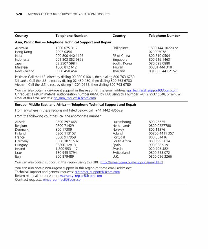
520 APPENDIX C: OBTAINING SUPPORT FOR YOUR 3COM PRODUCTS
Country Telephone Number Country Telephone Number
Asia, Pacific Rim — Telephone Technical Support and Repair
AustraliaHong KongIndiaIndonesiaJapanMalaysiaNew Zealand
1800 075 3162907 0456000 800 440 1193001 803 852 982503 3507 59841800 812 6120800 450 454
Philippines
PR of ChinaSingaporeSouth. KoreaTaiwanThailand
1800 144 10220 or029003078800 810 0504800 616 1463080 698 088000801 444 318001 800 441 2152
Pakistan Call the U.S. direct by dialing 00 800 01001, then dialing 800 763 6780Sri Lanka Call the U.S. direct by dialing 02 430 430, then dialing 800 763 6780Vietnam Call the U.S. direct by dialing 1 201 0288, then dialing 800 763 6780
You can also obtain non-urgent support in this region at this email address [email protected] Or request a return material authorization number (RMA) by FAX using this number: +61 2 9937 5048, or send an email at this email address: [email protected]
Europe, Middle East, and Africa — Telephone Technical Support and Repair
From anywhere in these regions not listed below, call: +44 1442 435529
From the following countries, call the appropriate number:
AustriaBelgiumDenmarkFinland FranceGermanyHungaryIrelandIsraelItaly
0800 297 4680800 71429800 173090800 1131530800 9179590800 182 150206800 128131 800 553 117180 945 3794800 879489
LuxembourgNetherlandsNorwayPolandPortugalSouth AfricaSpainSwedenSwitzerlandU.K.
800 236250800 0227788800 1137600800 4411 357800 8314160800 995 014900 938 919020 795 4820800 553 0720800 096 3266
You can also obtain support in this region using this URL: http://emea.3com.com/support/email.html
You can also obtain non-urgent support in this region at these email addresses:Technical support and general requests: [email protected] material authorization: [email protected] requests: [email protected]
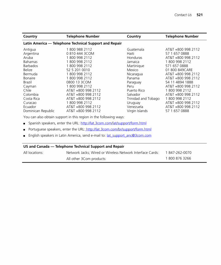
Contact Us 521
Latin America — Telephone Technical Support and Repair
AntiguaArgentinaArubaBahamasBarbadosBelizeBermudaBonaireBrazilCaymanChileColombiaCosta RicaCuracaoEcuadorDominican Republic
1 800 988 21120 810 444 3COM1 800 998 21121 800 998 21121 800 998 211252 5 201 00101 800 998 21121 800 998 21120800 13 3COM1 800 998 2112AT&T +800 998 2112AT&T +800 998 2112AT&T +800 998 21121 800 998 2112AT&T +800 998 2112AT&T +800 998 2112
GuatemalaHaitiHondurasJamaicaMartiniqueMexicoNicaraguaPanamaParaguayPeruPuerto RicoSalvadorTrinidad and TobagoUruguayVenezuelaVirgin Islands
AT&T +800 998 211257 1 657 0888AT&T +800 998 21121 800 998 2112571 657 088801 800 849CAREAT&T +800 998 2112AT&T +800 998 211254 11 4894 1888AT&T +800 998 21121 800 998 2112AT&T +800 998 21121 800 998 2112AT&T +800 998 2112AT&T +800 998 211257 1 657 0888
You can also obtain support in this region in the following ways:
■ Spanish speakers, enter the URL: http://lat.3com.com/lat/support/form.html
■ Portuguese speakers, enter the URL: http://lat.3com.com/br/support/form.html
■ English speakers in Latin America, send e-mail to: [email protected]
US and Canada — Telephone Technical Support and Repair
All locations: Network Jacks; Wired or Wireless Network Interface Cards:
All other 3Com products:
1 847-262-0070
1 800 876 3266
Country Telephone Number Country Telephone Number

522 APPENDIX C: OBTAINING SUPPORT FOR YOUR 3COM PRODUCTS
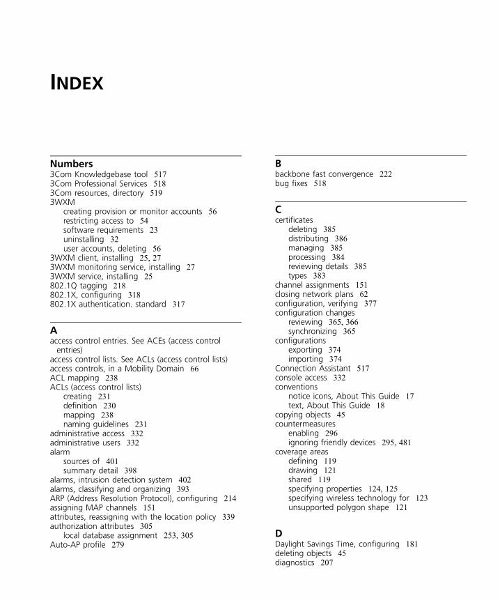
INDEX
Numbers3Com Knowledgebase tool 5173Com Professional Services 5183Com resources, directory 5193WXM
creating provision or monitor accounts 56restricting access to 54software requirements 23uninstalling 32user accounts, deleting 56
3WXM client, installing 25, 273WXM monitoring service, installing 273WXM service, installing 25802.1Q tagging 218802.1X, configuring 318802.1X authentication. standard 317
Aaccess control entries. See ACEs (access control
entries)access control lists. See ACLs (access control lists)access controls, in a Mobility Domain 66ACL mapping 238ACLs (access control lists)
creating 231definition 230mapping 238naming guidelines 231
administrative access 332administrative users 332alarm
sources of 401summary detail 398
alarms, intrusion detection system 402alarms, classifying and organizing 393ARP (Address Resolution Protocol), configuring 214assigning MAP channels 151attributes, reassigning with the location policy 339authorization attributes 305
local database assignment 253, 305Auto-AP profile 279
Bbackbone fast convergence 222bug fixes 518
Ccertificates
deleting 385distributing 386managing 385processing 384reviewing details 385types 383
channel assignments 151closing network plans 62configuration, verifying 377configuration changes
reviewing 365, 366synchronizing 365
configurationsexporting 374importing 374
Connection Assistant 517console access 332conventions
notice icons, About This Guide 17text, About This Guide 18
copying objects 45countermeasures
enabling 296ignoring friendly devices 295, 481
coverage areasdefining 119drawing 121shared 119specifying properties 124, 125specifying wireless technology for 123unsupported polygon shape 121
DDaylight Savings Time, configuring 181deleting objects 45diagnostics 207
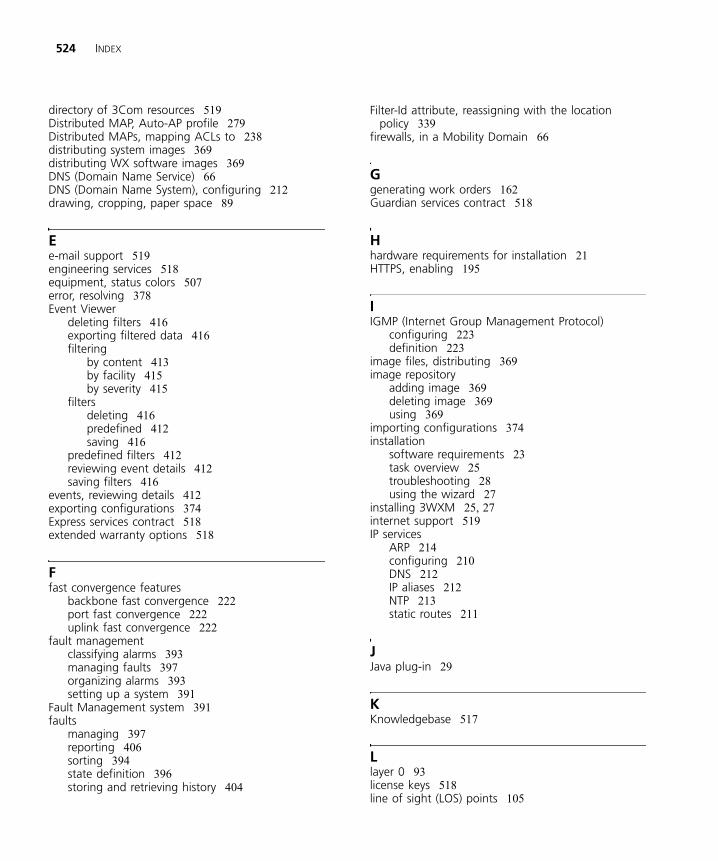
524 INDEX
directory of 3Com resources 519Distributed MAP, Auto-AP profile 279Distributed MAPs, mapping ACLs to 238distributing system images 369distributing WX software images 369DNS (Domain Name Service) 66DNS (Domain Name System), configuring 212drawing, cropping, paper space 89
Ee-mail support 519engineering services 518equipment, status colors 507error, resolving 378Event Viewer
deleting filters 416exporting filtered data 416filtering
by content 413by facility 415by severity 415
filtersdeleting 416predefined 412saving 416
predefined filters 412reviewing event details 412saving filters 416
events, reviewing details 412exporting configurations 374Express services contract 518extended warranty options 518
Ffast convergence features
backbone fast convergence 222port fast convergence 222uplink fast convergence 222
fault managementclassifying alarms 393managing faults 397organizing alarms 393setting up a system 391
Fault Management system 391faults
managing 397reporting 406sorting 394state definition 396storing and retrieving history 404
Filter-Id attribute, reassigning with the location policy 339
firewalls, in a Mobility Domain 66
Ggenerating work orders 162Guardian services contract 518
Hhardware requirements for installation 21HTTPS, enabling 195
IIGMP (Internet Group Management Protocol)
configuring 223definition 223
image files, distributing 369image repository
adding image 369deleting image 369using 369
importing configurations 374installation
software requirements 23task overview 25troubleshooting 28using the wizard 27
installing 3WXM 25, 27internet support 519IP services
ARP 214configuring 210DNS 212IP aliases 212NTP 213static routes 211
JJava plug-in 29
KKnowledgebase 517
Llayer 0 93license keys 518line of sight (LOS) points 105
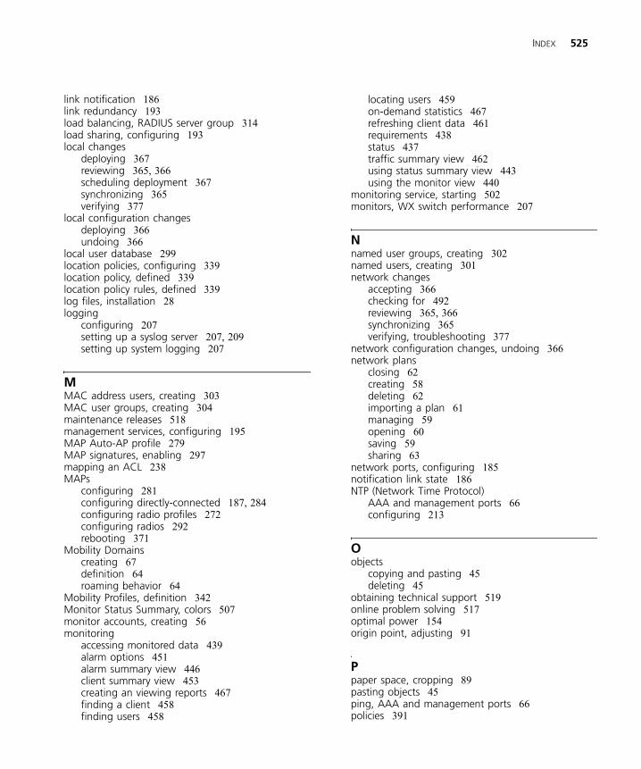
INDEX 525
link notification 186link redundancy 193load balancing, RADIUS server group 314load sharing, configuring 193local changes
deploying 367reviewing 365, 366scheduling deployment 367synchronizing 365verifying 377
local configuration changesdeploying 366undoing 366
local user database 299location policies, configuring 339location policy, defined 339location policy rules, defined 339log files, installation 28logging
configuring 207setting up a syslog server 207, 209setting up system logging 207
MMAC address users, creating 303MAC user groups, creating 304maintenance releases 518management services, configuring 195MAP Auto-AP profile 279MAP signatures, enabling 297mapping an ACL 238MAPs
configuring 281configuring directly-connected 187, 284configuring radio profiles 272configuring radios 292rebooting 371
Mobility Domainscreating 67definition 64roaming behavior 64
Mobility Profiles, definition 342Monitor Status Summary, colors 507monitor accounts, creating 56monitoring
accessing monitored data 439alarm options 451alarm summary view 446client summary view 453creating an viewing reports 467finding a client 458finding users 458
locating users 459on-demand statistics 467refreshing client data 461requirements 438status 437traffic summary view 462using status summary view 443using the monitor view 440
monitoring service, starting 502monitors, WX switch performance 207
Nnamed user groups, creating 302named users, creating 301network changes
accepting 366checking for 492reviewing 365, 366synchronizing 365verifying, troubleshooting 377
network configuration changes, undoing 366network plans
closing 62creating 58deleting 62importing a plan 61managing 59opening 60saving 59sharing 63
network ports, configuring 185notification link state 186NTP (Network Time Protocol)
AAA and management ports 66configuring 213
Oobjects
copying and pasting 45deleting 45
obtaining technical support 519online problem solving 517optimal power 154origin point, adjusting 91
Ppaper space, cropping 89pasting objects 45ping, AAA and management ports 66policies 391
526 INDEX
port link notification 186port fast convergence 222port groups
definition 193link redundancy 193
portsmapping ACLs to 238network 185wired authentication 188
power, optimal 154preferences
certificate management 494logging 499network synchronization 492resetting all preferences 491resetting tab values 491RF planning colors 495tools 493user interface 492
product registration 517, 518Professional Services from 3Com 518profile, Auto-AP 279provision accounts, creating 56purchasing license keys 518purchasing software upgrades 518
QQuickStart 51
Rradio profiles
configuring 272defined 272
radios, configuring 292RADIUS
accounting ports 66authentication 66
RADIUS (Remote Authentication Dial-In User Services) server groups
connecting to 311defining 314
RADIUS (Remote Authentication Dial-In User Services) servers
connecting to 311defining default values 315system accounting 317
RADIUS serverchanging default settings 315configuring system accounting 317creating a group 314modifying 313
rebootingMAPs 371WX switches 371
registering your product 517, 518, 519repair authorization number by FAX, Asia and Pacific
Rim 520repair services 519repair support for Latin America 521repair support for US and Canada 521repair support, Europe, Middle East, and Africa 520reports, work orders 162Restricted Software 518return authorization number (RMA) 519RF detection, configuring 293RF measurement point 158RF obstacles
considerations 100creating 100
RFC 3164, syslog servers 207RMA numbers 519roaming behavior 64rogue detection, configuring 293rogues
adding a client to the black list 484adding device to rogue list 482converting to a third party AP 482displaying details 475displaying information 474displaying the geographical location 478
rules, disabling or reenabling 381
Ssaving, network plans 59
with new name 60Secure Sockets Layer protocol (SSL), management
ports 66sending products to 3Com for repair 519service benefits 517, 519services, repair 519sites, defined 78SNMP (Simple Network Management Protocol)
configuring 196SNMP ports
for get and set operations 66for traps 66
software requirements for installation 23software upgrades contract 518solving problems online 517Spanning Tree Protocol. See STP (Spanning Tree
Protocol)SSH, enabling 195
INDEX 527
SSL management portsfor 3WXM 66for Web View 66
StarterKit 51starting 3WXM 49starting monitoring service 502static multicast ports, configuring 224static routes, configuring 211status colors 507Status Summary, colors 507STP (Spanning Tree Protocol)
backbone fast convergence 222configuring 219port fast convergence 222uplink fast convergence 222
summertime, configuring 181support, e-mail 519support, internet 519support, technical 519syslog server, setting up 207, 209system image files
adding 369deleting 369image repository 369managing 359
system images, distributing 369system information, configuring 182system logs, managing 207
Ttable of 3Com support contact numbers 519tag type 218technical support, Asia and Pacific Rim 520technical support, Europe, Middle East, and
Africa 520telephone support 519telephone technical support 518telephone technical support for Latin America 521telephone technical support for US and Canada 521telephone technical support, Asia and Pacific
Rim 520telephone technical support, Europe, Middle East,
and Africa 520Telnet, management port 66Telnet, configuring 195time zone, configuring 181traces
caution about levels 207running 207
tracing, configuring 207, 209traffic ports, typical, in a Mobility Domain 66
troubleshootingMSS debugging via trace 207MSS logging 207
tunnel affinity 227
Uuninstalling 3WXM 32uplink fast convergence 222user attributes 305user groups, creating 302, 304users
creating 301finding 458locating 459
Vverification, channel assignments 151virtual ports, mapping an ACL to 238VLAN-Name attribute, reassigning with the location
policy 339VLANs (virtual LANs)
adding ports to 218configuring
DHCP server 228IGMP 223static multicast ports 224STP fast convergence 222
creating 216definition 215mapping ACLs to 238roaming 216tagging 218tunnel affinity 227users 215
Wwarning, resolving 378warranty registration 517Web Portal, enabling 195Web-Start client 29wired authentication ports 188wireless services 245wiring closets, creating 118work orders, generating 162WX monitoring performance 207WX software images 369WX switches
managing configuration files 359managing system images 359rebooting 371

528 INDEX
WX-WX security, enabling 67
XX.509 certificate types 383