with aluminum roof
TRANSCRIPT
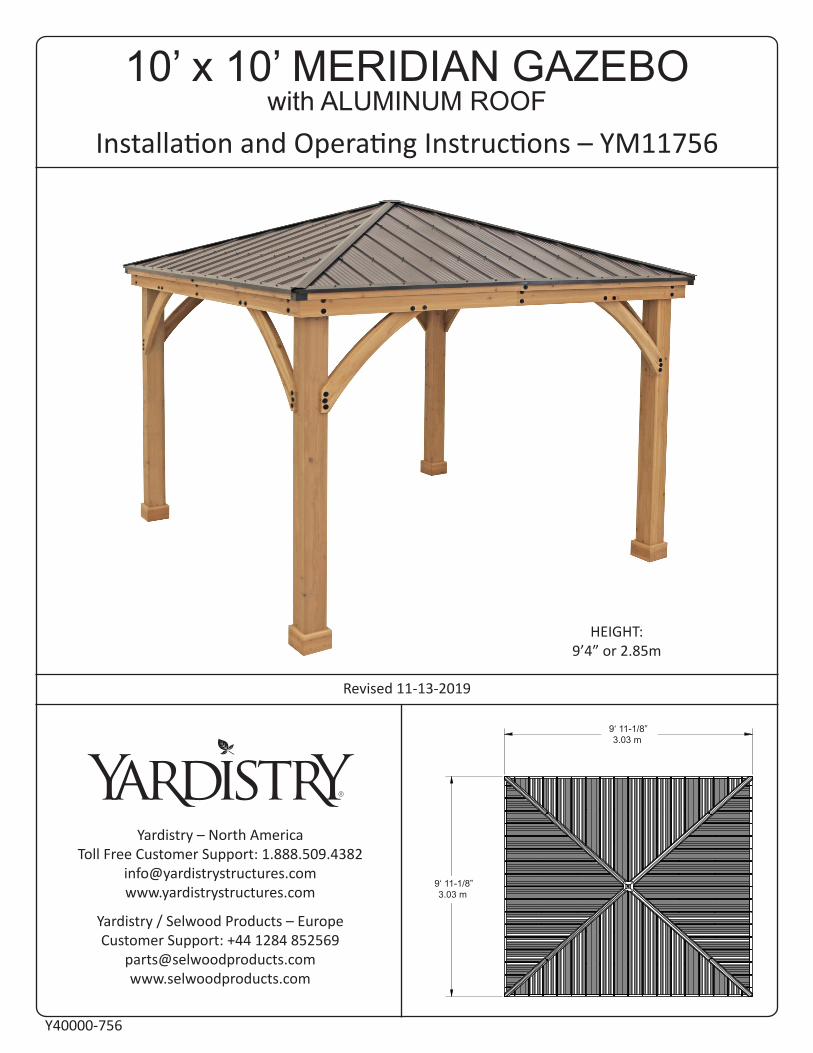
10’ x 10’ MERIDIAN GAZEBO with ALUMINUM ROOF
Installation and Operating Instructions – YM11756
Yardistry – North AmericaToll Free Customer Support: 1.888.509.4382
Yardistry / Selwood Products – EuropeCustomer Support: +44 1284 852569
Revised 11-13-2019
12'-1 5/32"
3687.1
12'-1 5/32"
3687.1
Y40000-756
HEIGHT:9’4” or 2.85m
9‘ 11-1/8”3.03 m
9‘ 11-1/8”3.03 m

Important Safety Notice!
Yardistry components are intended for privacy, decorative and ornamental use only.
Product is NOT INTENDED for the following: • A safety barrier to prevent unsupervised access to pools, hot tubs, spas or ponds. • As load bearing support for a building, structure, heavy objects or swings. • Used in structures that trap wind, rain or snow that would create extra load on the
product.
Accumulated snow must be removed from roof.
DO NOT climb or walk on roof for any reason.
Permanent structures may require a building permit. As the purchaser and or installer of this product you are advised to consult local planning, zoning and building inspection departments for guidance on applicable building codes and/or zoning requirements.
Wood is NOT flame retardant and will burn. Grills, fire pits and chimineas are a fire hazard if placed too close to a Yardistry structure. Consult user’s manual of the grill, fire pit or chimnea for safe distances from combustible materials.
Wear gloves to avoid injury from possible sharp edges of individual elements before assembly.
During installation, follow all safety warnings provided with your tools and use OHSA approved safety glasses. Some structures may require two or more people to install safely.
Check for underground utilities before digging or driving stakes into the ground!
It is important during assembly to closely follow the instructions, complete the assembly on a solid level surface and that you follow the instruction to square up, level and anchor the structure, this will reduce the gap at wood connections during assembly.
General Information: Wood components are manufactured with Cedar (C. Lanceolata) which is protected with factory applied water-based stain. Knots, small checks (cracks) and weathering are naturally occurring and do not affect the strength of the product. Annual application of a water-based water repellent sealant or stain is important and will help reduce weathering and checks.
www.yardistrystructures.com
Questions?
Call toll free or write us at:1 (888) 509-4382
Patents Pending
General Information

July 27, 2018
Limited Warranty
This Warranty gives you specific legal rights. You may have other rights as well which vary from state to state or province to province. This warranty excludes all consequential damages, however, some states/provinces do not allow the limitation or exclusion of consequential damages, and therefore this limitation may not apply to you.
Yardistry warrants that this product is free from defect in materials and workmanship for a period of one (1) year from the original date of purchase. In addition, for any product with lumber, all lumber is warranted for five (5) years against rot and decay. This warranty applies to the original owner and registrant and is non-transferable.
Regular maintenance is required to assure the integrity of your product and is a requirement of the warranty. This warranty does not cover any inspection costs.
This Limited Warranty does not cover:• Labour for replacement of any defective item(s);• Incidental or consequential damages;• Cosmetic defects which do not affect performance or integrity;• Vandalism; improper use or installation; acts of nature, including but not limited to wind,
storms, hail, floods, excessive water exposure;• Minor twisting, warping, checking or any other natural occurring properties of wood that do
not affect performance or integrity.
Yardistry products have been designed for safety and quality. Any modifications made to the original product could damage the structural integrity of the product leading to failure and possible injury. Yardistry cannot assume any responsibility for modified products. Furthermore, modification voids any and all warranties.
This product is warranted for RESIDENTIAL USE ONLY. Yardistry disclaims all other representations and warranties of any kind, express or implied.
Instructions for Proper Maintenance
Your Yardistry structure is designed and constructed of quality materials. As with all outdoor products it will weather and wear. To maximize the enjoyment, safety and life of your structure it is important that you, the owner, properly maintain it.
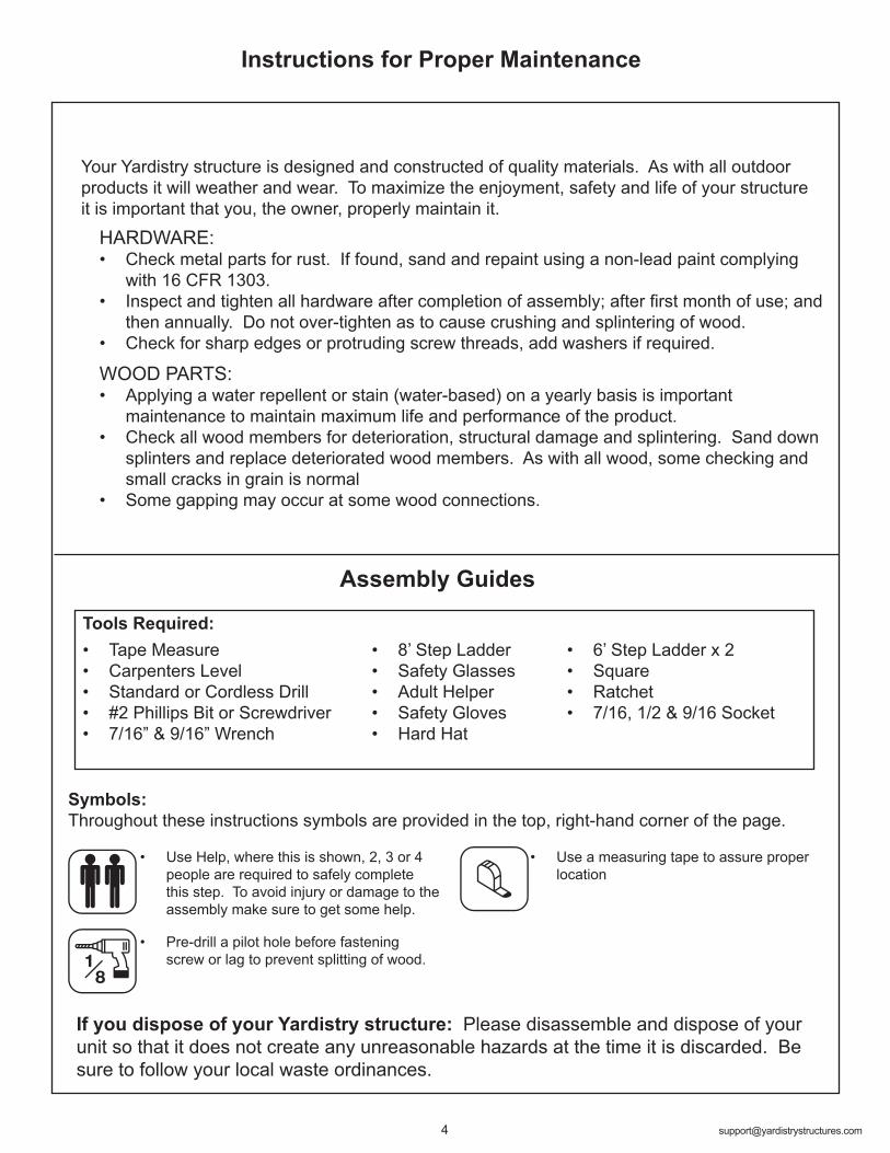
Symbols:Throughout these instructions symbols are provided in the top, right-hand corner of the page.
If you dispose of your Yardistry structure: Please disassemble and dispose of your unit so that it does not create any unreasonable hazards at the time it is discarded. Be sure to follow your local waste ordinances.
HARDWARE: • Check metal parts for rust. If found, sand and repaint using a non-lead paint complying
with 16 CFR 1303.• Inspect and tighten all hardware after completion of assembly; after first month of use; and
then annually. Do not over-tighten as to cause crushing and splintering of wood.• Check for sharp edges or protruding screw threads, add washers if required.
WOOD PARTS:• Applying a water repellent or stain (water-based) on a yearly basis is important
maintenance to maintain maximum life and performance of the product.• Check all wood members for deterioration, structural damage and splintering. Sand down
splinters and replace deteriorated wood members. As with all wood, some checking and small cracks in grain is normal
• Some gapping may occur at some wood connections.
• Tape Measure• Carpenters Level• Standard or Cordless Drill• #2 Phillips Bit or Screwdriver• 7/16” & 9/16” Wrench
Assembly Guides
• 8’ Step Ladder• Safety Glasses• Adult Helper• Safety Gloves• Hard Hat
Tools Required:
• Use Help, where this is shown, 2, 3 or 4 people are required to safely complete this step. To avoid injury or damage to the assembly make sure to get some help.
• Use a measuring tape to assure proper location
• Pre-drill a pilot hole before fastening screw or lag to prevent splitting of wood.
• 6’ Step Ladder x 2• Square• Ratchet• 7/16, 1/2 & 9/16 Socket
Following are some helpful tips to make the assembly process smooth and efficient.
PRE-ASSEMBLIES: (i.e. Post and Beam Assemblies, Roof Rafter Assembly, etc) • Work on a raised, solid and flat surface such as, a table or saw horse.• Keep all connections flush where shown in the instructions.• When assembling the beams keep parts flat, straight and snug when
connecting. METAL PARTS: • Roofing material may have sharp edges, wear safety gloves.• Remove all plastic covering, on both sides of the metal panels, directly
before installing each piece.• Place roofing material on a non-abrasive surface before and after assembly
as it can bend, dent and scratch easily.• The roofing screws can easily crush the roof panels and roof edges when
using a power drill. We recommend hand tightening the roofing screws so they sit snug and tight to the roofing material.
Assembly Tips
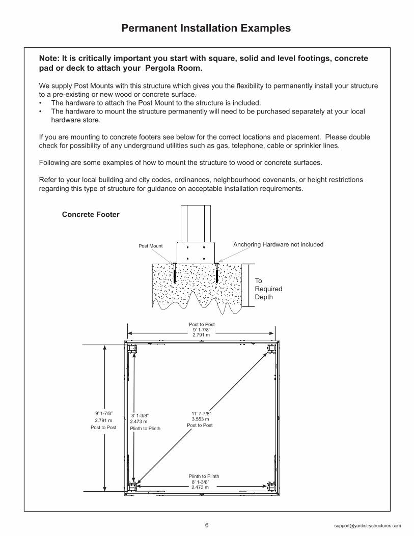
Note: It is critically important you start with square, solid and level footings, concrete pad or deck to attach your Pergola Room.
We supply Post Mounts with this structure which gives you the flexibility to permanently install your structure to a pre-existing or new wood or concrete surface. • The hardware to attach the Post Mount to the structure is included. • The hardware to mount the structure permanently will need to be purchased separately at your local
hardware store.
If you are mounting to concrete footers see below for the correct locations and placement. Please double check for possibility of any underground utilities such as gas, telephone, cable or sprinkler lines.
Following are some examples of how to mount the structure to wood or concrete surfaces.
Refer to your local building and city codes, ordinances, neighbourhood covenants, or height restrictions regarding this type of structure for guidance on acceptable installation requirements.
Permanent Installation Examples
Concrete Footer
To Required Depth
Anchoring Hardware not includedPost Mount
11’ 7-7/8”
Post to PostPost to Post Plinth to Plinth
8’ 1-3/8”
Post to Post9’ 1-7/8”
Plinth to Plinth8’ 1-3/8”2.473 m
2.473 m 3.553 m
2.791 m
9’ 1-7/8”2.791 m
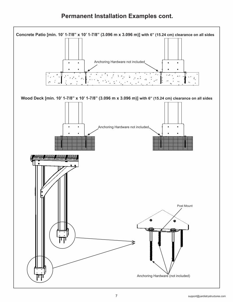
Permanent Installation Examples cont.
Concrete Patio [min. 10’ 1-7/8” x 10’ 1-7/8” (3.096 m x 3.096 m)] with 6” (15.24 cm) clearance on all sides
Wood Deck [min. 10’ 1-7/8” x 10’ 1-7/8” (3.096 m x 3.096 m)] with 6” (15.24 cm) clearance on all sides
Anchoring Hardware not included
Anchoring Hardware not included
Anchoring Hardware (not included)
Post Mount
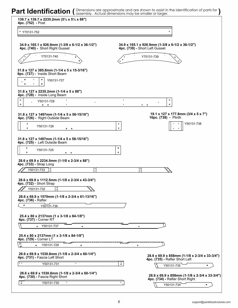
19.1 x 127 x 177.8mm (3/4 x 5 x 7")16pc. (738) - Plinth
Y50131-738
34.9 x 165.1 x 926.9mm (1-3/8 x 6-1/2 x 36-1/2") 4pc. (739) - Short Left Gusset
Y70131-739
Part Identification ( ) Dimensions are approximate and are shown to assist in the identification of parts for assembly. Actual dimensions may be smaller or larger.
139.7 x 139.7 x 2235.2mm (5½ x 5½ x 88")4pc. (752) - Post
Y70131-752
34.9 x 165.1 x 926.9mm (1-3/8 x 6-1/2 x 36-1/2") 4pc. (740) - Short Right Gusset
Y70131-740
Y50131-726
31.8 x 127 x 1497mm (1-1/4 x 5 x 58-15/16")4pc. (726) - Right Outside Beam
Y50131-732
28.6 x 69.9 x 1112.5mm (1-1/8 x 2-3/4 x 43-3/4")4pc. (732) - Short Strap
31.8 x 127 x 385.8mm (1-1/4 x 5 x 15-3/16")8pc. (727) - Inside Short Beam
Y50131-727
Y50131-728
31.8 x 127 x 2235.2mm (1-1/4 x 5 x 88")4pc. (728) - Inside Long Beam
31.8 x 127 x 1497mm (1-1/4 x 5 x 58-15/16")4pc. (725) - Left Outside Beam
Y50131-725
28.6 x 69.9 x 2234.5mm (1-1/8 x 2-3/4 x 88")4pc. (733) - Strap Long
Y50131-733
Y50131-729
25.4 x 80 x 2137mm (1 x 3-1/8 x 84-1/8")4pc. (729) - Corner LT
Y50131-734
28.6 x 69.9 x 858mm (1-1/8 x 2-3/4 x 33-3/4")4pc. (734) - Rafter Short Right
Y50131-731
28.6 x 69.9 x 1530.8mm (1-1/8 x 2-3/4 x 60-1/4")4pc. (731) - Fascia Left Short
28.6 x 69.9 x 1570mm (1-1/8 x 2-3/4 x 61-13/16")4pc. (736) - Rafter
Y50131-736
25.4 x 80 x 2137mm (1 x 3-1/8 x 84-1/8")4pc. (737) - Corner RT
Y50131-737
Y50131-730
28.6 x 69.9 x 1530.8mm (1-1/8 x 2-3/4 x 60-1/4")4pc. (730) - Fascia Right Short
Y50131-735
28.6 x 69.9 x 858mm (1-1/8 x 2-3/4 x 33-3/4")4pc. (735) - Rafter Short Left
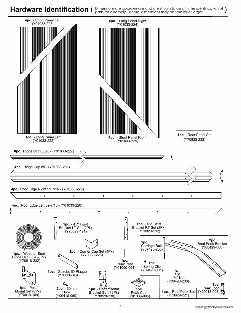
1pc.Carriage Bolt(Y07490-260)
1pc. - Roof Peak Set(Y70829-221)
Dimensions are approximate and are shown to assist in the identification of parts for assembly. Actual dimensions may be smaller or larger.Hardware Identification ( )
1pc.Peak Post
(Y01000-094)
1pc. - Weather Seal Ridge Clip 85¼ (8Pk)
(Y70818-232)
1pc.Peak Loop
(Y20018-003)2pc. - 50mm
Hook(Y00418-050)
1pc.Spring Clip
(Y09490-001)
4pc. - Short Panel Left(Y01033-223)
1pc.1/4" Nut
(Y08490-200)
1pc. - Gazebo ID Plaque (Y70800-104)
1pc. - Corner Cap Set (4Pk) (Y70833-226)
1pc. - Roof Panel Set(Y70833-233)4pc. - Long Panel Left
(Y01033-222)
1pc. - Post Mount Set (8Pk) (Y70819-109)
1pc.Peak Cap
(Y01033-095)
4pc. - Short Panel Right(Y01033-225)
4pc. - Long Panel Right(Y01033-224)
8pc. Ridge Clip 85.25 - (Y01033-227)
1pc. - Rafter/Beam Bracket Set (12Pk)
(Y70829-230)
4pc. Ridge Cap 85 - (Y01033-231)
1pc. - 45º Twist Bracket RT Set (2Pk)
(Y70829-192)
4pc. Roof Edge Right 59 7/16 - (Y01033-229)
4pc. Roof Edge Left 59-7/16 - (Y01033-228)
1pc. - 45º Twist Bracket LT Set (2Pk)
(Y70829-191)
2pc.Roof Peak Bracket
(Y00429-068)

24pc. Wood Screw #8 x 2" - (Y06091-520)
1pc. - 1/8 " Drill Bit
(Y00 400-002 )
Hardware Identification ( )Dimensions are approximate and are shown to assist in the identification of parts for assembly. Actual dimensions may be smaller or larger.
1pc. #2 x 2" Robertson Driver (Y00400-005)
98pc. Pan Screw #10 x 1-1/4" (Y06491-711)
52pc. 5/16" Lock Washer (Y05318-300)
52pc. 5/16 - T-Nut (Y08518-300)
8pc. - 3/8" Lock Nut(Y08318-803)
36pc. Hex Bolt 5/16 x 1-1/4" - (Y07718-311)
8pc. Lag Screw 5/16 x 4-3/4" - (Y06218-343)
24pc. Sheet Metal Screw #8 x 3/4"
(Y06433-503)
160pc. Wood Screw #8 x 1-1/2" (Y06091-512)
12pc. 1/4 x 2-3/4 Hex Bolt - (Y07718-223)
168pc. Hex Roofing Screw #8x 1"
(Y06733-510)
1pc. - Hex Driver (Y00400-004)
72pc. Wood Screw #8 x 2 1/4" - (Y06091-521)
16pc. 3/8 x 1-1/4" Large Washer
(Y05118-811)
24pc. - 1/4" Lock Nut(Y08318-203)
32pc. Wood Screw #7 x 3/4" (Y06091-003)
132pc. 1/4-5/16 x 1-1/4" Large Washer
(Y05118-311)
24pc. Lag Screw 1/4" x 1-15/16" No.12 Shank - (Y06218-219)
16pc. Hex Bolt 5/16 x 3-1/4" - (Y07718-331)
12pc. 1/4 x 2" Hex Bolt - (Y07718-220)
8pc. Hex Bolt3/8 x 8-1/2"
(Y07718-882)

PRODUCT NUMBER: YM11756CARTON I.D. STAMP: __ __ __ __ __ ___ (Box 1)
CARTON I.D. STAMP: __ __ __ __ __ ___ (Box 2)
CARTON I.D. STAMP: __ __ __ __ __ ___ (Box 3)
STOP STOPSTOP STOP
C. Read the assembly manual completely, paying special attention to ANSI warnings; notes; and safety/maintenance information on pages 1 - 4.
• Follow the instructions in order. • This structure is designed to be assembled and installed ideally by four people,
DO NOT attempt to install alone. • Consider the slope of elevation where you plan to install the structure. Also, check for
gas, telephone, other utilities or sprinkler line locations prior to excavating any holes.
D. Before you discard your cartons fill out the form below.
• The carton I.D. stamp is located on the end of each carton. • Please retain this information for future reference. You will need this information if you
contact the Consumer Relations Department.
• Each step indicates which bolts and/or screws you will need for assembly, as well as any flat washers, lock washers, t-nuts or lock nuts.
A. This is the time for you to inventory all your hardware, wood and accessories, referencing the parts identification sheets. This will assist you with your assembly.
Step 1: Inventory Parts - Read This Before Starting Assembly
B. If there are any missing or damaged pieces or you need assistance with assembly please contact the consumer relations department directly. Call us before going back to the store.
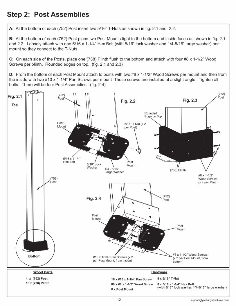
A: At the bottom of each (752) Post insert two 5/16” T-Nuts as shown in fig. 2.1 and 2.2.
B: At the bottom of each (752) Post place two Post Mounts tight to the bottom and inside faces as shown in fig. 2.1 and 2.2. Loosely attach with one 5/16 x 1-1/4” Hex Bolt (with 5/16” lock washer and 1/4-5/16” large washer) per mount so they connect to the T-Nuts.
C: On each side of the Posts, place one (738) Plinth flush to the bottom and attach with four #8 x 1-1/2” Wood Screws per plinth. Rounded edges on top. (fig. 2.1 and 2.3)
D: From the bottom of each Post Mount attach to posts with two #8 x 1-1/2” Wood Screws per mount and then from the inside with two #10 x 1-1/4” Pan Screws per mount These screws are installed at a slight angle. Tighten all bolts. There will be four Post Assemblies. (fig. 2.4)
Step 2: Post Assemblies
HardwareWood Parts
Fig. 2.2
(738) Plinth
4 x (752) Post 16 x (738) Plinth
Top
Bottom #8 x 1-1/2” Wood Screws (x 2 per Post Mount, from bottom)
#8 x 1-1/2” Wood Screws (x 4 per Plinth)
Post Mount
Fig. 2.3
16 x #10 x 1-1/4” Pan Screw80 x #8 x 1-1/2” Wood Screw8 x Post Mount
8 x 5/16” T-Nut
8 x 5/16 x 1-1/4” Hex Bolt (with 5/16” lock washer, 1/4-5/16” large washer)
Fig. 2.1
Post Mount
(752) Post
Rounded Edge on Top
Fig. 2.4
Post Mount
#10 x 1-1/4” Pan Screws (x 2 per Post Mount, from inside)
1/4 - 5/16” Large Washer
5/16” Lock Washer
5/16 x 1-1/4” Hex Bolt
5/16” T-Nut (x 2 per Post)
Post Mount
(752) Post
(752) Post
(752) Post

3
3
Step 3: Beam Assembly Part 1
HardwareWood Parts
A: Connect one (725) Left Outside Beam and one (726) Right Outside Beam using two 5/16 x 1-1/4” Hex Bolts (with 5/16” lock washer, 1/4 - 5/16” large washer and 5/16” t-nut) as shown in fig. 3.1 and 3.2.
B: Connect one (727) Inside Short Beam to each end of one (728) Inside Long Beam using two 5/16 x 1-1/4” Hex Bolts (with 5/16” lock washer, 1/4 - 5/16” large washer and 5/16” t-nut) per end as shown in fig. 3.1 and 3.2.
C: Repeat Steps A and B three more times to make four Outside Beam Assemblies and four Inside Beam Assemblies.
(725) Left Outside Beam
4 x (725) Left Outside Beam4 x (726) Right Outside Beam8 x (727) Inside Short Beam4 x (728) Inside Long Beam
Fig. 3.1
24 x 5/16 x 1-1/4” Hex Bolt (5/16” lock washer, 1/4-5/16” large washer, 5/16” t-nut)
Fig. 3.2
1/4 -5/16” Large Washer5/16 x 1-1/4”
Hex Bolt
5/16” T-nut
Tight
(726) Right Outside Beam
(728) Inside Long Beam
(727) Inside Short Beam
5/16” Lock Washer
Make sure bolt heads are on the outside of each Beam Assembly
(727) Inside Short Beam

Hardware52 x #8 x 2-1/4” Wood Screw
Fig. 3.3
Inside Beam Assembly
Fig. 3.4
Flush
Outside Beam Assembly
Step 3: Beam Assembly Part 2
D: Place one Outside Beam Assembly on one Inside Beam Assembly so the ends are flush. Match the bolt holes in each (727) Inside Short Beam and (728) Inside Long Beam with the bolt holes in (725) Left Outside Beam and (726) Right Outside Beam. Attach with 13 #8 x 2-1/4” Wood Screws. (fig. 3.3 and 3.4)
E: Repeat Step D three more times to make four Beam Assemblies.
Flush
Outside Beam Assembly
#8 x 2-1/4” Wood Screws (x 13 per assembly)
(728)
(727)
(727)
Match bolt holes
Inside Beam Assembly
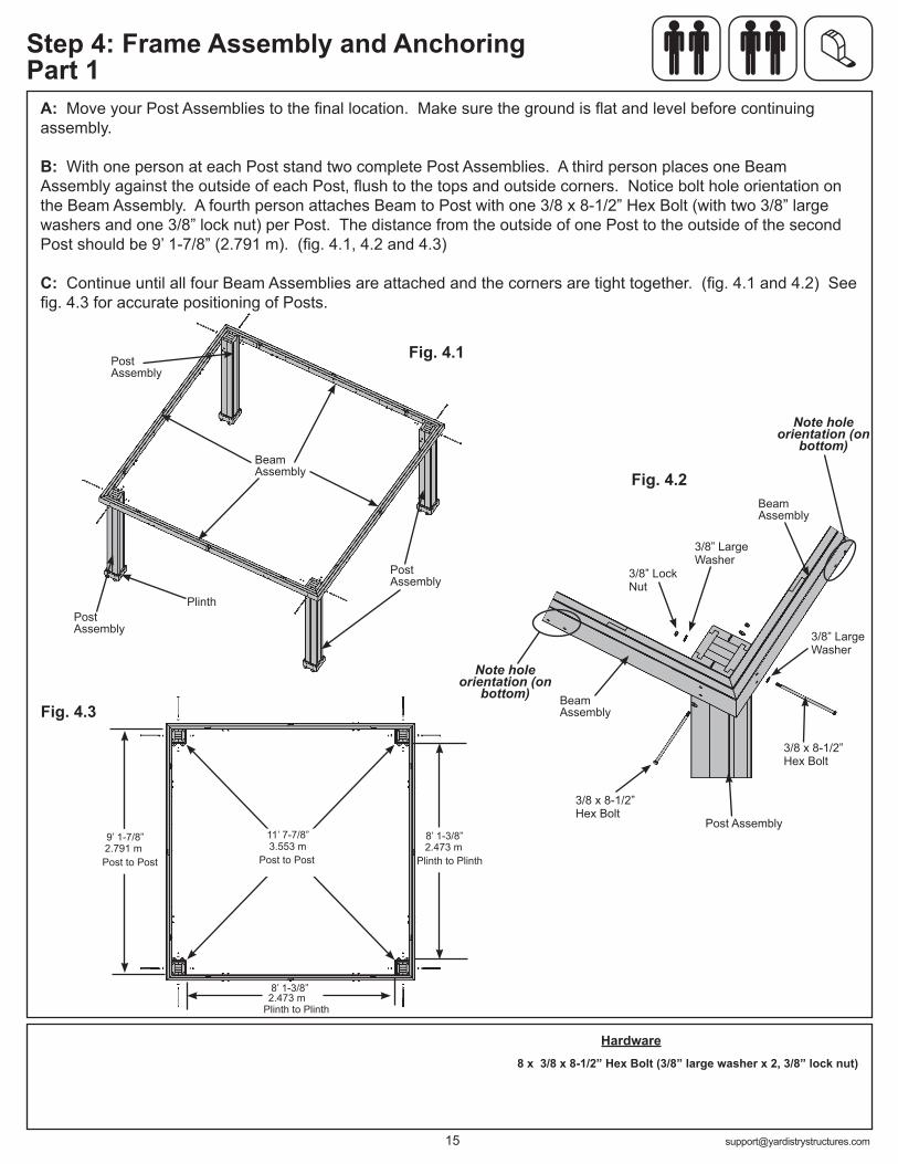
Step 4: Frame Assembly and Anchoring Part 1
Fig. 4.1
A: Move your Post Assemblies to the final location. Make sure the ground is flat and level before continuing assembly.
B: With one person at each Post stand two complete Post Assemblies. A third person places one Beam Assembly against the outside of each Post, flush to the tops and outside corners. Notice bolt hole orientation on the Beam Assembly. A fourth person attaches Beam to Post with one 3/8 x 8-1/2” Hex Bolt (with two 3/8” large washers and one 3/8” lock nut) per Post. The distance from the outside of one Post to the outside of the second Post should be 9’ 1-7/8” (2.791 m). (fig. 4.1, 4.2 and 4.3)
C: Continue until all four Beam Assemblies are attached and the corners are tight together. (fig. 4.1 and 4.2) See fig. 4.3 for accurate positioning of Posts.
Fig. 4.2
Hardware8 x 3/8 x 8-1/2” Hex Bolt (3/8” large washer x 2, 3/8” lock nut)
Note hole orientation (on
bottom)Fig. 4.3
3/8” Lock Nut
3/8” Large Washer
3/8” Large Washer
3/8 x 8-1/2” Hex Bolt
3/8 x 8-1/2” Hex Bolt
Beam Assembly
Beam Assembly
Beam Assembly
Post Assembly
Post Assembly
Post Assembly
Post Assembly
Plinth to Plinth
Plinth to PlinthPost to PostPost to Post
Plinth
Note hole orientation (on
bottom)
11’ 7-7/8”9’ 1-7/8”
8’ 1-3/8”
8’ 1-3/8”2.473 m2.791 m
2.473 m
3.553 m
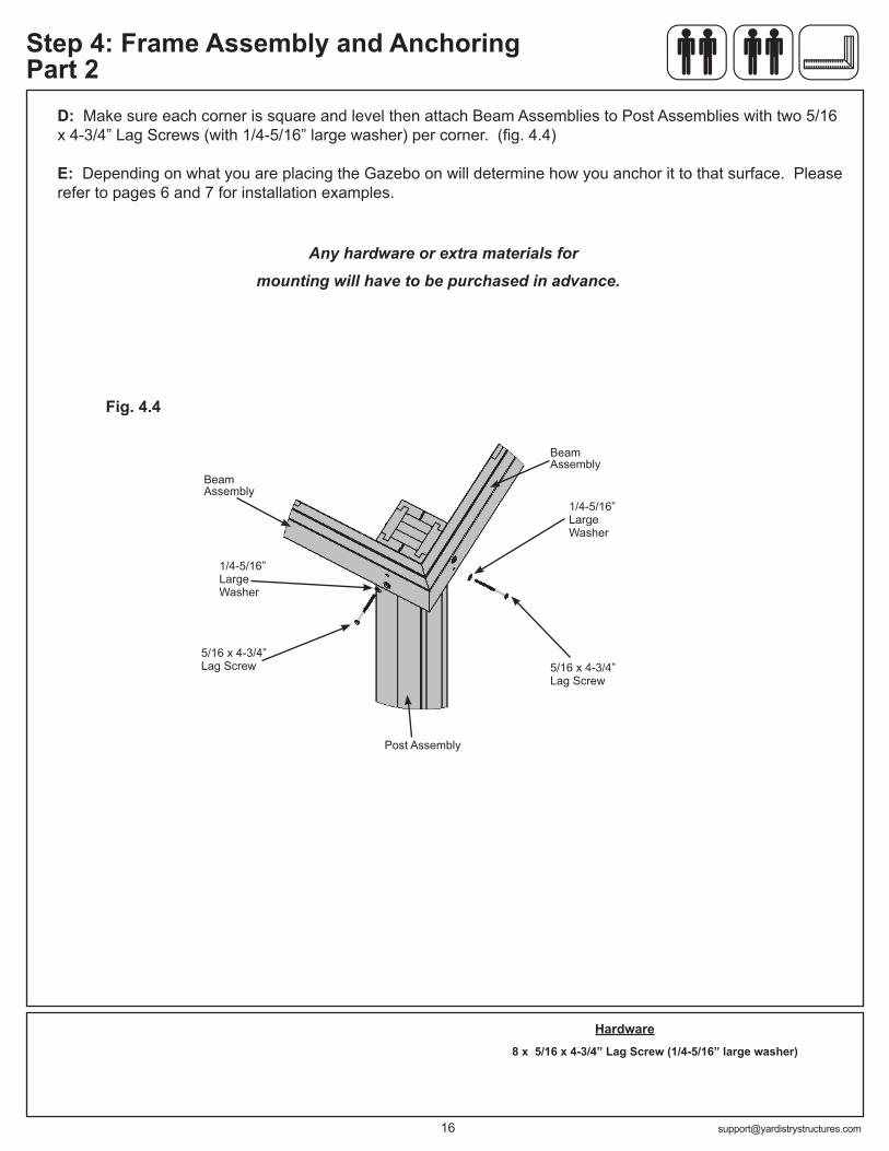
D: Make sure each corner is square and level then attach Beam Assemblies to Post Assemblies with two 5/16 x 4-3/4” Lag Screws (with 1/4-5/16” large washer) per corner. (fig. 4.4)
E: Depending on what you are placing the Gazebo on will determine how you anchor it to that surface. Please refer to pages 6 and 7 for installation examples.
Any hardware or extra materials for mounting will have to be purchased in advance.
Hardware8 x 5/16 x 4-3/4” Lag Screw (1/4-5/16” large washer)
1/4-5/16” Large Washer
5/16 x 4-3/4” Lag Screw
5/16 x 4-3/4” Lag Screw
Fig. 4.4
Beam Assembly
Beam Assembly
Post Assembly
Step 4: Frame Assembly and Anchoring Part 2
1/4-5/16” Large Washer

Note: The bevelled ends on each gusset should always face away from the wood it is attaching to.
A: Make sure the assembly is still square and level then facing one Beam Assembly place one (740) Short Right Gusset on the right hand side so the top fits tight to the Beam Assembly and the bottom fits tight to the Post Assembly. Attach gusset to Beam Assembly with two 5/16 x 3-1/4” Hex Bolts (with 5/16” lock washer, 1/4-5/16” large washer and 5/16” t-nut) and to Post Assembly with three 1/4 x 1-15/16” Hex Lags (with 1/4-5/16” large washer). (fig. 5.1, 5.2 and 5.3)
B: Repeat Step A on the left hand side with one (739) Short Left Gusset. (fig. 5.1, 5.2 and 5.3)
C: Repeat Steps A and B for each Beam Assembly/Post Assembly. (fig. 5.1, 5.2 and 5.3)
Step 5: Attach Gussets
Fig. 5.1
HardwareWood Parts
Fig. 5.2
Fig. 5.3
Tight
Post Assembly
Post Assembly
1/4 x 1-15/16” Hex Lag
5/16” T-nut5/16” Lock Washer 1/4-5/16”
Large Washer
5/16 x 3-1/4” Hex Bolt
5/16 x 3-1/4” Hex Bolt
Beam Assembly
Beam Assembly
1/4-5/16” Large Washer
1/4-5/16” Large Washer
1/4 x 1-15/16” Hex Lag
(739) Short Left Gusset(740) Short
Right Gusset
4 x (740) Short Right Gusset4 x (739) Short Left Gusset
24 x 1/4 x 1-15/16” Hex Lag (1/4-5/16” large washer)16 x 5/16 x 3-1/4” Hex Bolt (5/16” lock washer, 1/4-5/16” large washer, 5/16” t-nut)
(739) Short Left Gusset
(740) Short Right Gusset
(739) Short Left Gusset
(740) Short Right Gusset
(739) Short Left Gusset
(740) Short Right Gusset (739) Short
Left Gusset
(740) Short Right Gusset
(739) Short Left Gusset
(740) Short Right Gusset
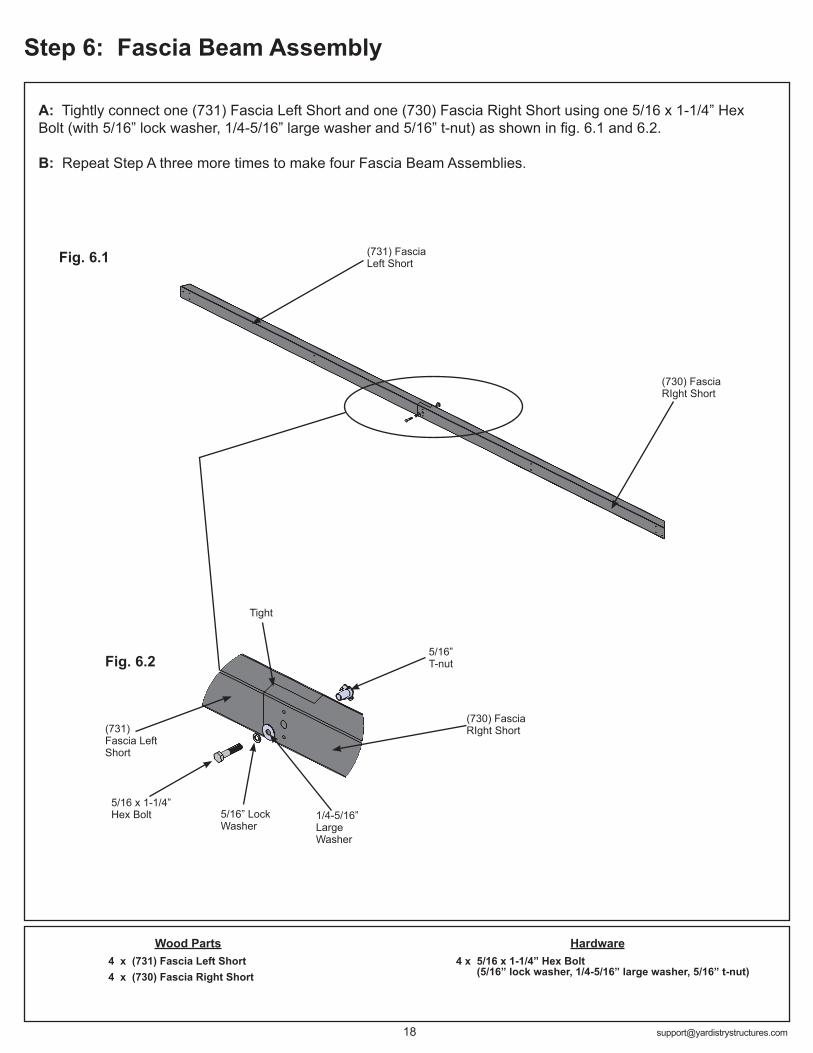
A: Tightly connect one (731) Fascia Left Short and one (730) Fascia Right Short using one 5/16 x 1-1/4” Hex Bolt (with 5/16” lock washer, 1/4-5/16” large washer and 5/16” t-nut) as shown in fig. 6.1 and 6.2.
B: Repeat Step A three more times to make four Fascia Beam Assemblies.
Step 6: Fascia Beam Assembly
Fig. 6.1
Fig. 6.2
HardwareWood Parts4 x (731) Fascia Left Short4 x (730) Fascia Right Short
4 x 5/16 x 1-1/4” Hex Bolt (5/16” lock washer, 1/4-5/16” large washer, 5/16” t-nut)
(730) Fascia RIght Short
(731) Fascia Left Short
(730) Fascia RIght Short(731)
Fascia Left Short
1/4-5/16” Large Washer
5/16” T-nut
5/16 x 1-1/4” Hex Bolt
Tight
5/16” Lock Washer
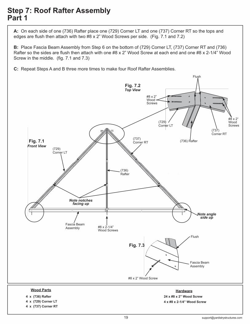
A: On each side of one (736) Rafter place one (729) Corner LT and one (737) Corner RT so the tops and edges are flush then attach with two #8 x 2” Wood Screws per side. (Fig. 7.1 and 7.2)
B: Place Fascia Beam Assembly from Step 6 on the bottom of (729) Corner LT, (737) Corner RT and (736) Rafter so the sides are flush then attach with one #8 x 2” Wood Screw at each end and one #8 x 2-1/4” Wood Screw in the middle. (fig. 7.1 and 7.3)
C: Repeat Steps A and B three more times to make four Roof Rafter Assemblies.
9
9
9
HardwareWood Parts
#8 x 2” Wood Screw
Top View
Fascia Beam Assembly
Step 7: Roof Rafter Assembly Part 1
Fig. 7.1
24 x #8 x 2” Wood Screw4 x #8 x 2-1/4” Wood Screw
4 x (736) Rafter 4 x (729) Corner LT 4 x (737) Corner RT
Fig. 7.3
Note notches facing up
Flush
Fascia Beam Assembly
(736) Rafter
#8 x 2“ Wood Screws
#8 x 2” Wood Screws
Flush
Fig. 7.2
(729) Corner LT
Front View
Note angle side up
(736) Rafter
#8 x 2-1/4” Wood Screws
(737) Corner RT
(729) Corner LT
(737) Corner RT

10
HardwareWood Parts
#8 x 1-1/2” Wood Screws x 20 per assembly
Fig. 7.4
Step 7: Roof Rafter Assembly Part 2
80 x #8 x 1-1/2” Wood Screw8 x #8 x 2-1/4” Wood Screw
4 x (732) Short Strap4 x (733) Strap Long4 x (734) Rafter Short Right4 x (735) Rafter Short Left
D: Place one (732) Short Strap in the notches of (729) Corner LT, (737) Corner RT and (736) Rafter so the ends do not overhang the outside edges of the outside boards then attach with six #8 x 1-1/2” Wood Screws. (Fig. 7.4)
E: Place one (733) Strap Long in the notches of (729) Corner LT, (737) Corner RT and (736) Rafter so the ends do not overhang the outside edges of the outside boards. Attach to (729) Corner LT, (737) Corner RT and (736) Rafter with six #8 x 1-1/2” Wood Screws. (fig. 7.4)
F: Place one (734) Rafter Short Right and one (735) Rafter Short Left in the notches of (733) Strap Long and attach as shown in fig. 7.4 with four #8 x 1-1/2” Wood Screws and two #8 x 2-1/4” Wood Screws per board.
G: Complete Steps D, E and F for all four Roof Rafter Assemblies.
(736) Rafter
No Overhang
Fascia Beam Assembly
(729) Corner LT
(737) Corner RT
Front View
Flush
(732) Short Strap
(735) Rafter Short Left
(733) Strap Long
(734) Rafter Short Right
#8 x 2-1/4” Wood Screws
#8 x 2-1/4” Wood Screws

Hardware
Rafter Beam Bracket
Fig. 8.1
Fig. 8.2
A: On the back of three Roof Rafter Assemblies place one Rafter Beam Bracket on each (734) Rafter Short Right, (735) Rafter Short Left and (736) Rafter. Loosely attach each bracket to rafters with one 1/4 x 2” Hex Bolt (with two 1/4-5/16” large washers and one 1/4” lock nut). (fig. 8.1 and 8.2)
Step 8: Attach Roof to Beam Brackets
9 x 1/4 x 2” Hex Bolt (1/4-5/16” large washer x 2, 1/4” lock nut)
Back View
(736)
(735) (734)
Componets:9 x Rafter Beam Bracket
1/4” Lock Nut
1/4 x 2” Hex Bolt
1/4-5/16” Large Washer
1/4-5/16” Large Washer

INSTALLING ROOFING MATERIAL
CAUTION! Roofing material may have sharp edges! Wear gloves!
HANDLE WITH CARE!Place roofing material on a non-abrasive surface before assembly as it
can bend, dent and scratch easily.
WARNING – DO NOT OVER TIGHTEN ROOFING SCREWS!Over tightening screws will cause roofing material to crush.
The roofing screws can easily crush the Roof Panels and Roof Edges when using a power drill. We recommend hand tightening the roofing screws so that they sit snug and tight to the roofing material.
STOP STOPSTOP STOP
Overtightened and Crushed Snug and Tight
X

INSTALLING ROOFING MATERIALCAUTION!
Roofing material may have sharp edges! Wear gloves!
BE SURE TO REMOVE ALL PLASTIC COVERING, ON BOTH SIDES OF THE ALUMINUM PANELS AND TRIM,
DIRECTLY BEFORE INSTALLING EACH PIECE. (One side is clear and the other is blue, both must be removed.)
STOP STOPSTOP STOP
Overtightened and Crushed Snug and Tight
Example #1 Example #2
Example #3
Hardware
#8 x 1” Roofing Screws
Step 9: Attach Roof Panels Part 1
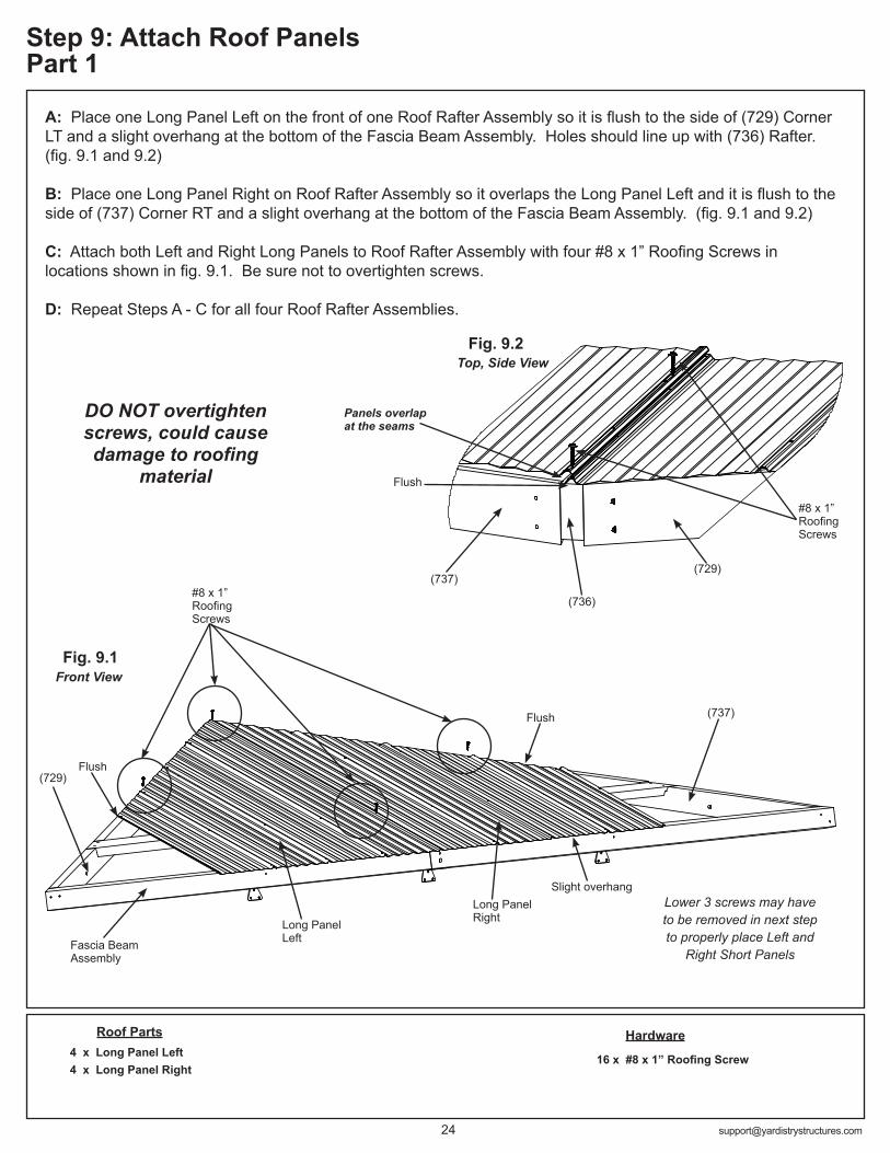
A: Place one Long Panel Left on the front of one Roof Rafter Assembly so it is flush to the side of (729) Corner LT and a slight overhang at the bottom of the Fascia Beam Assembly. Holes should line up with (736) Rafter. (fig. 9.1 and 9.2)
B: Place one Long Panel Right on Roof Rafter Assembly so it overlaps the Long Panel Left and it is flush to the side of (737) Corner RT and a slight overhang at the bottom of the Fascia Beam Assembly. (fig. 9.1 and 9.2)
C: Attach both Left and Right Long Panels to Roof Rafter Assembly with four #8 x 1” Roofing Screws in locations shown in fig. 9.1. Be sure not to overtighten screws.
D: Repeat Steps A - C for all four Roof Rafter Assemblies.
Fig. 9.1
Fig. 9.2
16 x #8 x 1” Roofing Screw
Roof Parts4 x Long Panel Left4 x Long Panel Right
Front View
Fascia Beam Assembly
(729)
(737)
Top, Side View
Panels overlap at the seams
(736)
(737) (729)
#8 x 1” Roofing Screws
Long Panel Left
Long Panel Right
DO NOT overtighten screws, could cause damage to roofing
material
Flush
Flush
Slight overhangLower 3 screws may have to be removed in next step to properly place Left and
Right Short Panels
Flush
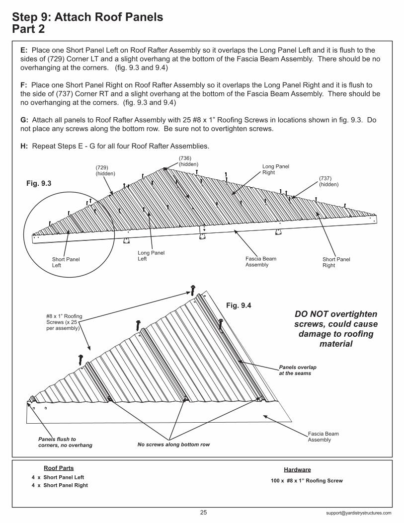
Fig. 9.4
Fig. 9.3
Hardware
100 x #8 x 1” Roofing Screw
Roof Parts4 x Short Panel Left4 x Short Panel Right
Step 9: Attach Roof Panels Part 2
E: Place one Short Panel Left on Roof Rafter Assembly so it overlaps the Long Panel Left and it is flush to the sides of (729) Corner LT and a slight overhang at the bottom of the Fascia Beam Assembly. There should be no overhanging at the corners. (fig. 9.3 and 9.4)
F: Place one Short Panel Right on Roof Rafter Assembly so it overlaps the Long Panel Right and it is flush to the side of (737) Corner RT and a slight overhang at the bottom of the Fascia Beam Assembly. There should be no overhanging at the corners. (fig. 9.3 and 9.4)
G: Attach all panels to Roof Rafter Assembly with 25 #8 x 1” Roofing Screws in locations shown in fig. 9.3. Do not place any screws along the bottom row. Be sure not to overtighten screws.
H: Repeat Steps E - G for all four Roof Rafter Assemblies.
(729) (hidden)
(737) (hidden)
(736) (hidden)
#8 x 1” Roofing Screws (x 25 per assembly)
Short Panel Left
Panels flush to corners, no overhang
Panels overlap at the seams
Fascia Beam Assembly
Fascia Beam Assembly
No screws along bottom row
DO NOT overtighten screws, could cause damage to roofing
material
Long Panel Left
Long Panel Right
Short Panel Right
Tight at centre
Step 10: Attach Ridge Clips and Roof Edges
Hardware
Fig. 10.1
52 x #8 x 1” Roofing Screw32 x #7 x 3/4” Wood Screw
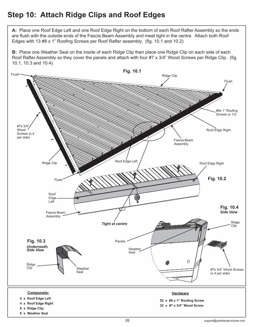
A: Place one Roof Edge Left and one Roof Edge Right on the bottom of each Roof Rafter Assembly so the ends are flush with the outside ends of the Fascia Beam Assembly and meet tight in the centre. Attach both Roof Edges with 13 #8 x 1” Roofing Screws per Roof Rafter assembly. (fig. 10.1 and 10.2)
B: Place one Weather Seal on the inside of each Ridge Clip then place one Ridge Clip on each side of each Roof Rafter Assembly so they cover the panels and attach with four #7 x 3/4” Wood Screws per Ridge Clip. (fig. 10.1, 10.3 and 10.4)
Weather Seal
Ridge Clip
Fig. 10.2
#7x 3/4” Wood Screws (x 4 per side)
Panels
Componets:4 x Roof Edge Left 4 x Roof Edge Right8 x Ridge Clip8 x Weather Seal
Ridge Clip
Roof Edge Left
Roof Edge Right
Fascia Beam Assembly
Flush
Flush
#8x 1” Roofing Screws (x 13)
Roof Edge Left
Roof Edge Right
Fascia Beam Assembly
Fig. 10.3Weather Seal
Underneath, Side View
Ridge Clip
Fig. 10.4Side View
#7x 3/4” Wood Screws (x 4 per side)
Ridge Clip
Flush
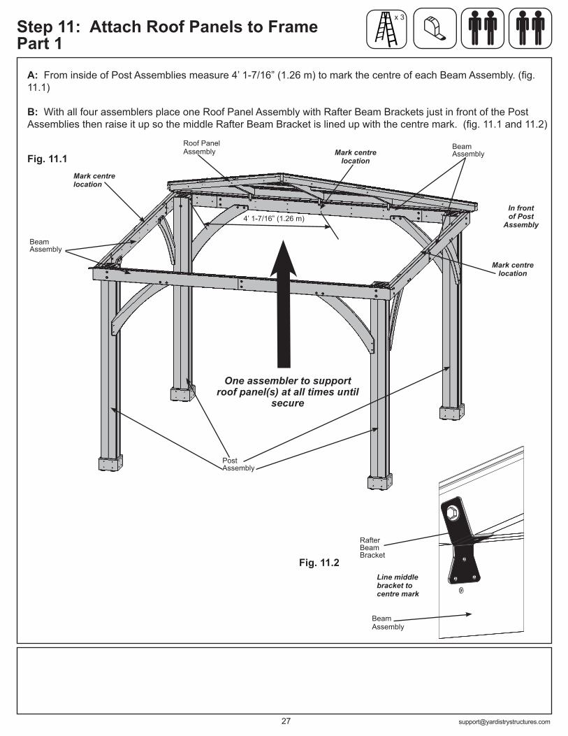
A: From inside of Post Assemblies measure 4’ 1-7/16” (1.26 m) to mark the centre of each Beam Assembly. (fig. 11.1)
B: With all four assemblers place one Roof Panel Assembly with Rafter Beam Brackets just in front of the Post Assemblies then raise it up so the middle Rafter Beam Bracket is lined up with the centre mark. (fig. 11.1 and 11.2)
Step 11: Attach Roof Panels to Frame Part 1
Fig. 11.1
In front of Post
Assembly
Beam Assembly
Post Assembly
4’ 1-7/16” (1.26 m)
Roof Panel Assembly
Mark centre location
Mark centre location
Mark centre location
x 3
Beam Assembly
Rafter Beam Bracket
Fig. 11.2
Beam Assembly
Line middle bracket to centre mark
One assembler to support roof panel(s) at all times until
secure

Step 11: Attach Roof Panels to Frame Part 2
Fig. 11.4
C: Lift a second Roof Panel Assembly with Rafter Beam Brackets over Beam Assembly taking care not to drag the panel on the beams. Make sure the middle Rafter Beam Bracket lines up to the centre mark and (729) Corner LT and (737) Corner RT are flush with each other. One person must remain on the centre ladder to hold both panels in place until three panels are up and secure. (fig. 11.2, 11.3 and 11.4)
D: Starting at the bottom and working up connect Roof Panel Assemblies through (729) Corner LT and (737) Corner RT with three 1/4 x 2-3/4” Hex Bolts (with two 1/4-5/16” large washers and one 1/4” lock nut). To align bolt holes helper in the centre may have to push up the centre of the panels and others make sure corners are aligned. Make sure all bolts are tight. (fig. 11.2 and 11.5)
Fig. 11.2
Flush
Fig. 11.3
x 3
Fig. 11.5
Hardware
3 x 1/4 x 2-3/4” Hex Bolt (1/4-5/16” large washer x 2, 1/4” lock nut)
Corner LT & RT
1/4” Lock Nut
1/4 x 2-3/4” Hex Bolt
Roof Panel Assembly
Make sure corners are aligned
Roof Panel Assembly
Start at bottom and work up the rafters
1/4-5/16” Large Washer
One assembler to support roof panel(s) at all
times until secure
Corner LT & RT
Rafter Beam Bracket
Beam Assembly
Line middle bracket to centre mark
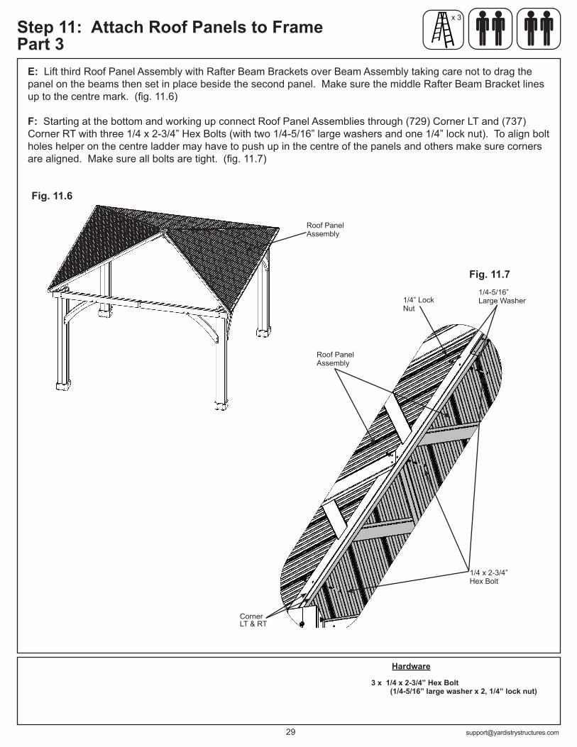
Fig. 11.6
E: Lift third Roof Panel Assembly with Rafter Beam Brackets over Beam Assembly taking care not to drag the panel on the beams then set in place beside the second panel. Make sure the middle Rafter Beam Bracket lines up to the centre mark. (fig. 11.6)
F: Starting at the bottom and working up connect Roof Panel Assemblies through (729) Corner LT and (737) Corner RT with three 1/4 x 2-3/4” Hex Bolts (with two 1/4-5/16” large washers and one 1/4” lock nut). To align bolt holes helper on the centre ladder may have to push up in the centre of the panels and others make sure corners are aligned. Make sure all bolts are tight. (fig. 11.7)
Roof Panel Assembly
Fig. 11.7
Hardware
3 x 1/4 x 2-3/4” Hex Bolt (1/4-5/16” large washer x 2, 1/4” lock nut)
Step 11: Attach Roof Panels to Frame Part 3
x 3
Roof Panel Assembly
1/4-5/16” Large Washer1/4” Lock
Nut
1/4 x 2-3/4” Hex Bolt
Corner LT & RT
Peak Cap
Carriage Bolt
Peak Loop
Spring Clip
1/4” Nut
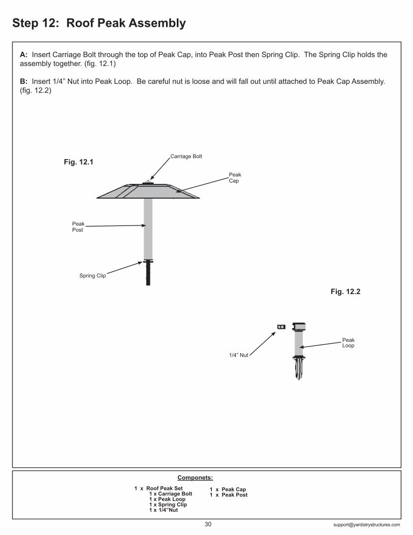
A: Insert Carriage Bolt through the top of Peak Cap, into Peak Post then Spring Clip. The Spring Clip holds the assembly together. (fig. 12.1)
B: Insert 1/4” Nut into Peak Loop. Be careful nut is loose and will fall out until attached to Peak Cap Assembly. (fig. 12.2)
Fig. 12.1
Peak Post
Componets:1 x Roof Peak Set 1 x Carriage Bolt 1 x Peak Loop 1 x Spring Clip 1 x 1/4”Nut
1 x Peak Cap1 x Peak Post
Step 12: Roof Peak Assembly
Fig. 12.2
Peak Cap
Carriage Bolt
Fig. 13.3
Peak Loop
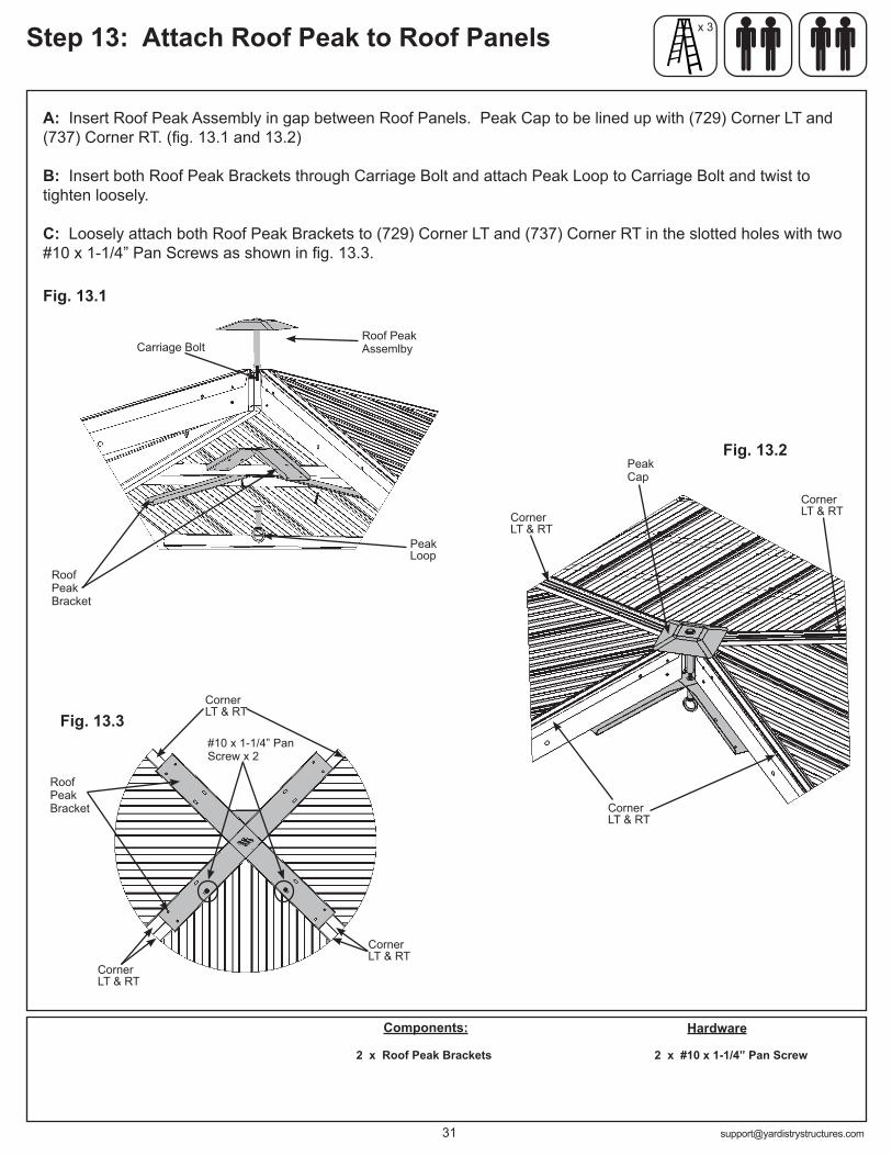
A: Insert Roof Peak Assembly in gap between Roof Panels. Peak Cap to be lined up with (729) Corner LT and (737) Corner RT. (fig. 13.1 and 13.2)
B: Insert both Roof Peak Brackets through Carriage Bolt and attach Peak Loop to Carriage Bolt and twist to tighten loosely.
C: Loosely attach both Roof Peak Brackets to (729) Corner LT and (737) Corner RT in the slotted holes with two #10 x 1-1/4” Pan Screws as shown in fig. 13.3.
Fig. 13.1
Roof Peak Bracket
Roof Peak Assemlby
Components:
2 x Roof Peak Brackets
Step 13: Attach Roof Peak to Roof Panels x 3
Fig. 13.2
Roof Peak Bracket
#10 x 1-1/4” Pan Screw x 2
Hardware
2 x #10 x 1-1/4” Pan Screw
Corner LT & RT
Corner LT & RT
Corner LT & RT
Corner LT & RT
Corner LT & RT
Corner LT & RT
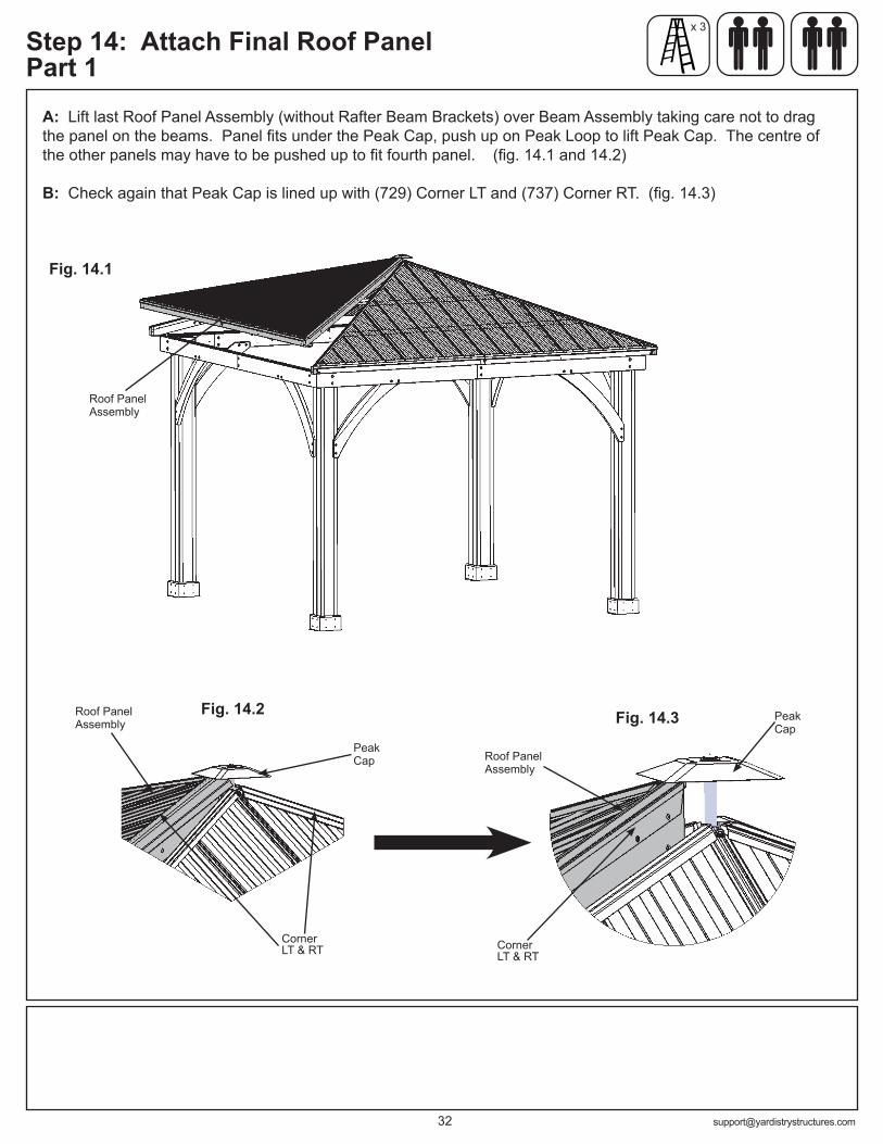
Fig. 14.2
Fig. 14.1
A: Lift last Roof Panel Assembly (without Rafter Beam Brackets) over Beam Assembly taking care not to drag the panel on the beams. Panel fits under the Peak Cap, push up on Peak Loop to lift Peak Cap. The centre of the other panels may have to be pushed up to fit fourth panel. (fig. 14.1 and 14.2)
B: Check again that Peak Cap is lined up with (729) Corner LT and (737) Corner RT. (fig. 14.3)
Roof Panel Assembly
Peak Cap
Roof Panel Assembly
Step 14: Attach Final Roof Panel Part 1
x 3
Peak Cap
Roof Panel Assembly
Fig. 14.3
Corner LT & RT
Corner LT & RT

Remember to push up centre to assist with alignment.
C: Starting at the bottom and working up loosely connect Roof Panel Assemblies through (729) Corner LT and (737) Corner RT with three 1/4 x 2-3/4” Hex Bolts (with two 1/4-5/16” large washers and one 1/4” lock nut) per side. To align bolt holes helper on the centre ladder may have to push up in the centre of the panels and others make sure corners are aligned. Tighten bolts when all six have been installed. (fig. 14.4 and 14.5)
(729) Corner LT and (737) Corner RT should be aligned with mitre in Beam Assembly. (fig. 14.6)
Hardware
1/4” Lock Nut
1/4 x 2-3/4” Hex Bolt
Fig. 14.4
Fig. 14.5
Roof Panel Assembly
Bottom holes first
x 3Step 14: Attach Final Roof Panel Part 2
6 x 1/4 x 2-3/4” Hex Bolt (1/4-5/16” large washer x 2, 1/4” lock nut)
1/4-5/16” Large Washer
Corner LT & RT
Fig. 14.6
Corner LT and RT aligned with mitre in Beam Assembly
Parts removed for clarity

x 3
Fig. 14.7
Parts removed for clarity
Attach to Rafter Short Right, Rafter Short Left and Rafter
Step 14: Attach Final Roof Panel Part 3
Hardware
Rafter Beam Bracket
A: On the fourth Roof Rafter Assembly, place one Rafter Beam Bracket on each (734) Rafter Short Right, (735) Rafter Short Left and (736) Rafter. Loosely attach each bracket to rafters with one 1/4 x 2” Hex Bolt (with two 1/4-5/16” large washers and one 1/4” lock nut). (fig. 14.7)
Componets:3 x Rafter Beam Bracket
1/4” Lock Nut
1/4 x 2” Hex Bolt
1/4-5/16” Large Washer
1/4-5/16” Large Washer
3 x 1/4 x 2” Hex Bolt (1/4-5/16” large washer x 2, 1/4” lock nut)

Hardware8 x #8 x 2-1/4” Wood Screw
A: Make sure middle Rafter Beam Brackets are lined up over centre mark and all are flush and tight to the Beam Assemblies. (729) Corner LT and (737) Corner RT should be aligned with mitre in Beam Assembly Lift in centre if needed to adjust Roof Panel Assemblies.
B: From outside the assembly attach Roof Panel Assemblies together at the Fascia Beam Assembly Ends with two #8 x 2-1/4” Wood Screws per corner. A helper may need to lift the centre of the roof to bring the corners tight together. (fig. 15.1 and 15.2)
Fig. 15.1
Fig. 15.2
Fascia Beam Assembly
Fascia Beam Assembly
Fascia Beam Assembly
Fascia Beam Assembly
Roof Edge Left
#8 x2-1/4” Wood Screw
#8 x2-1/4” Wood Screw
Step 15: Secure Roof Cornersx 3
Note: You will need to lift Roof Edge Left at the corner to
install the top screw
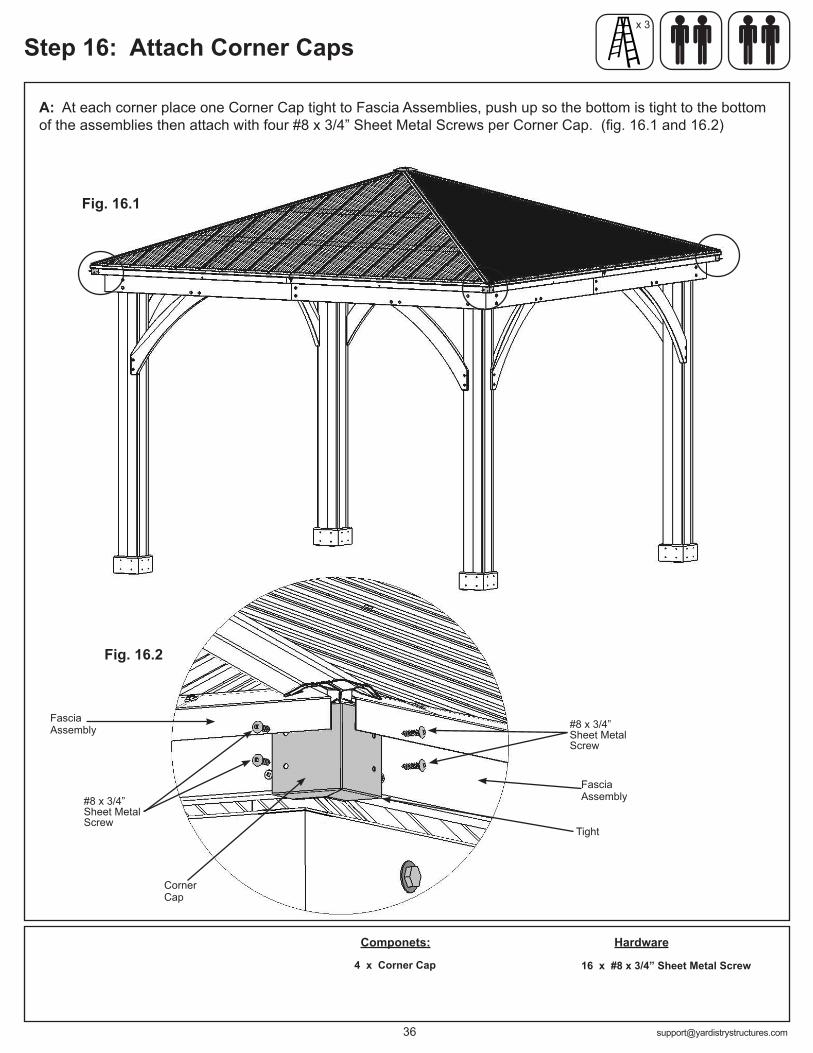
A: At each corner place one Corner Cap tight to Fascia Assemblies, push up so the bottom is tight to the bottom of the assemblies then attach with four #8 x 3/4” Sheet Metal Screws per Corner Cap. (fig. 16.1 and 16.2)
Hardware
16 x #8 x 3/4” Sheet Metal Screw
Componets:
4 x Corner Cap
Corner Cap
Fascia Assembly
Fig. 16.1
Fig. 16.2
#8 x 3/4” Sheet Metal Screw
Fascia Assembly
Tight
x 3
Step 16: Attach Corner Caps
#8 x 3/4” Sheet Metal Screw

A: From inside the assembly attach Rafter Beam Brackets to Beam Assemblies and rafters with four #10 x 1-1/4” Pan Screws per bracket. (fig. 17.1 and 17.2)
B: Tighten all bolts in Rafter Beam Brackets. (fig. 17.1 and 17.2)
Hardware48 x #10 x 1-1/4” Pan Screw
x 3
Step 17: Secure Rafter Beam Brackets
Inside View
Beam Assembly
Fig. 17.1
Roof Panel Assembly
Fig. 17.2
Rafter Beam Bracket
#10 x 1-1/4” Pan Screw
Beam Assembly
Tighten all Rafter Beam Bracket bolts
Step 18: Secure Roof Peak Brackets
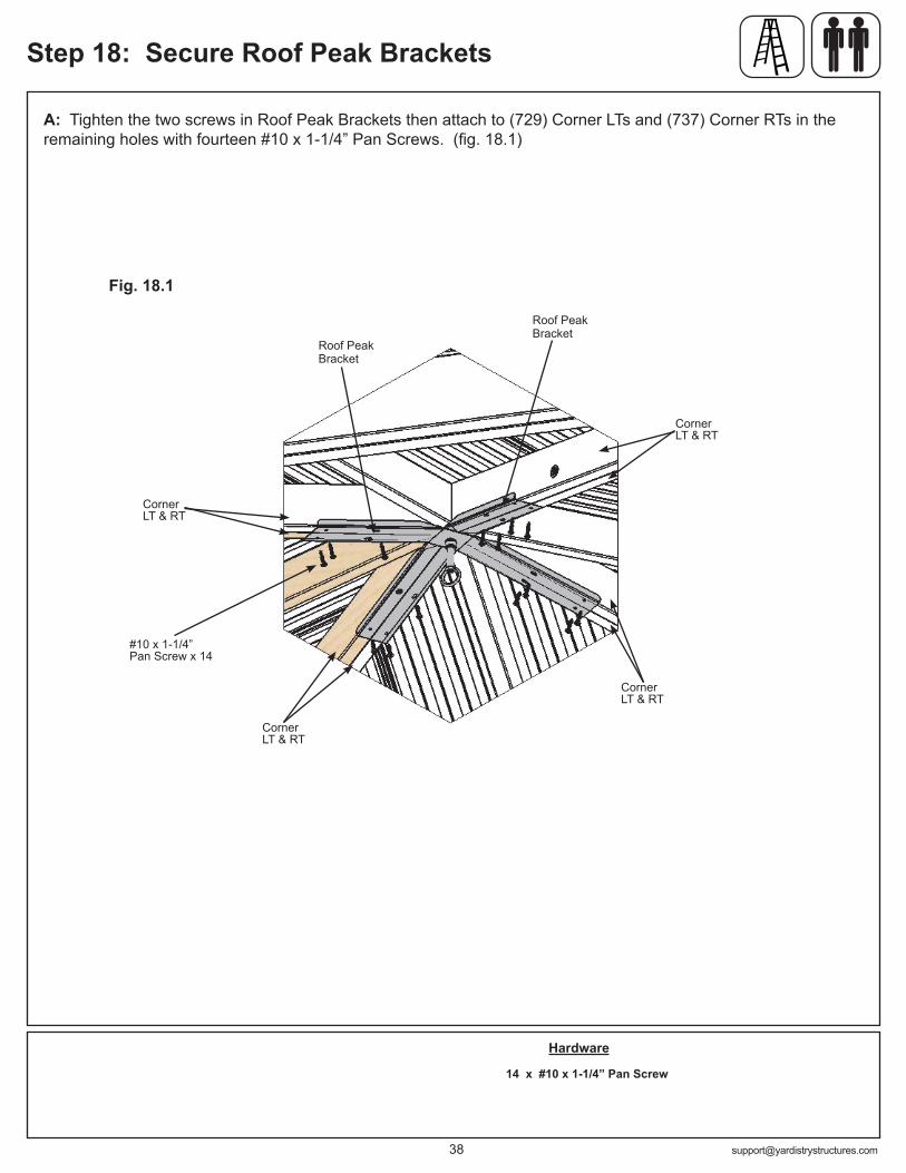
A: Tighten the two screws in Roof Peak Brackets then attach to (729) Corner LTs and (737) Corner RTs in the remaining holes with fourteen #10 x 1-1/4” Pan Screws. (fig. 18.1)
Hardware
14 x #10 x 1-1/4” Pan Screw
Fig. 18.1
Roof Peak Bracket
Roof Peak Bracket
#10 x 1-1/4” Pan Screw x 14
Corner LT & RT
Corner LT & RT
Corner LT & RT
Corner LT & RT
Step 19: Attach Ridge Caps to Roof Panels
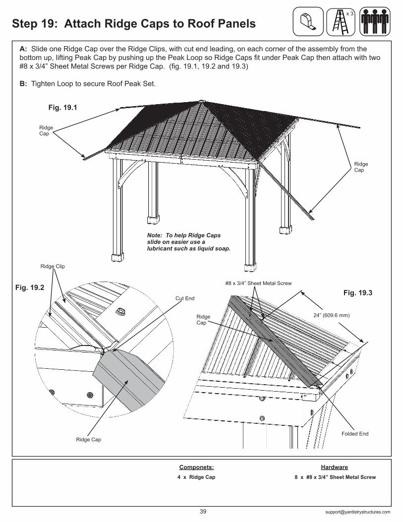
A: Slide one Ridge Cap over the Ridge Clips, with cut end leading, on each corner of the assembly from the bottom up, lifting Peak Cap by pushing up the Peak Loop so Ridge Caps fit under Peak Cap then attach with two #8 x 3/4” Sheet Metal Screws per Ridge Cap. (fig. 19.1, 19.2 and 19.3)
B: Tighten Loop to secure Roof Peak Set.
Hardware8 x #8 x 3/4” Sheet Metal Screw
Componets:4 x Ridge Cap
Ridge Cap
Ridge Cap
Ridge Cap
Ridge Clip
#8 x 3/4” Sheet Metal Screw
Ridge Cap
Fig. 19.1
Fig. 19.2Fig. 19.3
x 3
Cut End
Folded End
24” (609.6 mm)
Note: To help Ridge Caps slide on easier use a lubricant such as liquid soap.
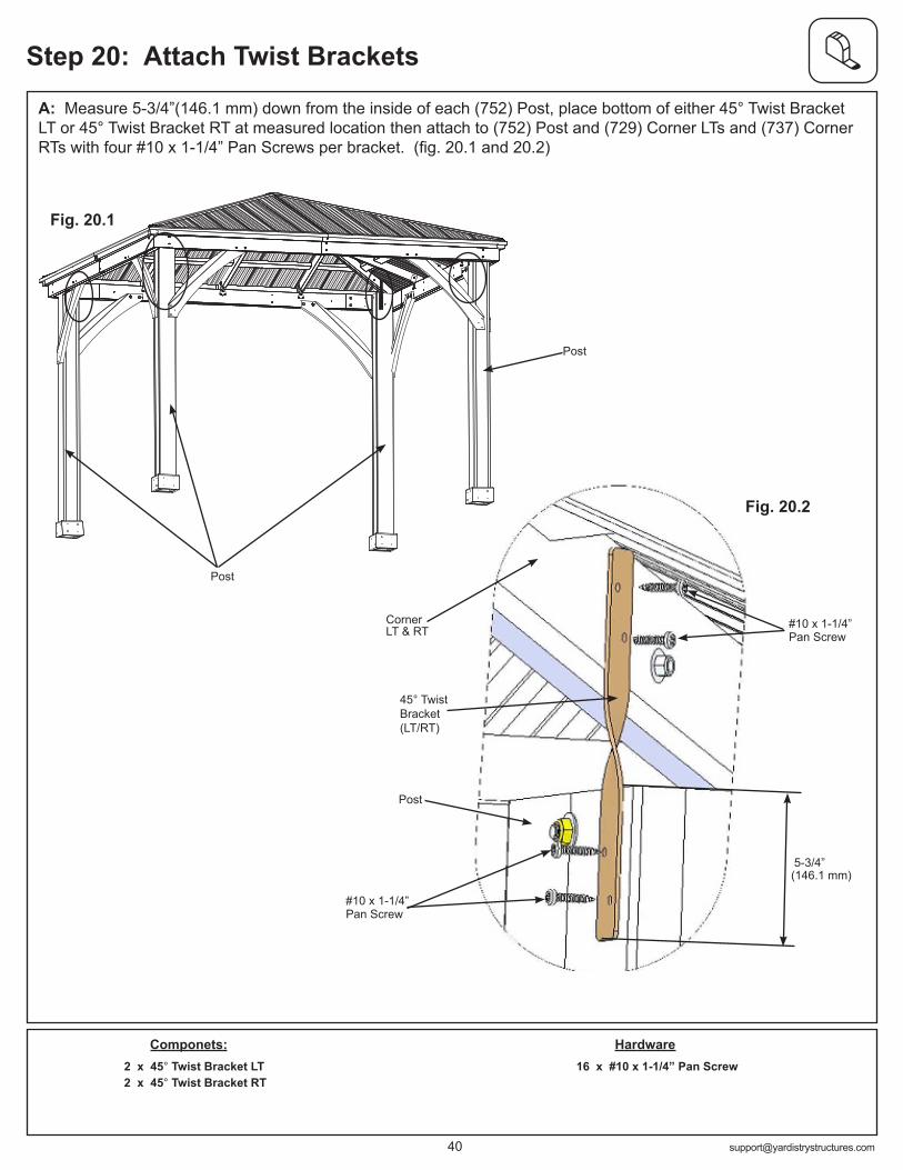
A: Measure 5-3/4”(146.1 mm) down from the inside of each (752) Post, place bottom of either 45° Twist Bracket LT or 45° Twist Bracket RT at measured location then attach to (752) Post and (729) Corner LTs and (737) Corner RTs with four #10 x 1-1/4” Pan Screws per bracket. (fig. 20.1 and 20.2)
Step 20: Attach Twist Brackets
Componets:2 x 45° Twist Bracket LT2 x 45° Twist Bracket RT
45° Twist Bracket (LT/RT)
#10 x 1-1/4” Pan Screw
Hardware16 x #10 x 1-1/4” Pan Screw
Fig. 20.1
5-3/4”
#10 x 1-1/4” Pan Screw
Fig. 20.2
Corner LT & RT
Post
Post
Post
(146.1 mm)
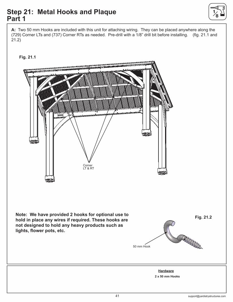
Step 21: Metal Hooks and Plaque Part 1
A: Two 50 mm Hooks are included with this unit for attaching wiring. They can be placed anywhere along the (729) Corner LTs and (737) Corner RTs as needed. Pre-drill with a 1/8” drill bit before installing. (fig. 21.1 and 21.2)
Hardware2 x 50 mm Hooks
Fig. 21.1
Fig. 21.2
50 mm Hook
Note: We have provided 2 hooks for optional use to hold in place any wires if required. These hooks are not designed to hold any heavy products such as lights, flower pots, etc.
Corner LT & RT

Step 21: Metal Hooks and Plaque Part 2
B: Attach Gazebo ID Plaque to a prominent location on your gazebo with two #10 x 1-1/4” Pan Screws. This provides warnings concerning safety and important contact information. A tracking number is provided to allow you to get critical information or order replacement parts for this specific model. (fig. 21.3 and 21.4)
2 x #10 x 1-1/4” Pan Screw
Fig. 21.3
Fig. 21.4#10 x 1-1/4” Pan Screw
Gazebo ID Plaque
HardwareComponets:1 x Gazebo ID Plaque

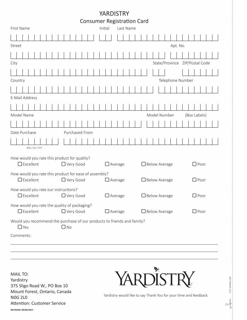
YARDISTRY Consumer Registration Card
First Name Initial Last Name
Street Apt. No.
City State/Province ZIP/Postal Code
Country Telephone Number
E-Mail Address
Model Name Model Number (Box Labels)
Date Purchase Purchased From
How would you rate this product for quality? Excellent Very Good Average Below Average Poor
How would you rate this product for ease of assembly? Excellent Very Good Average Below Average Poor
How would you rate our instructions? Excellent Very Good Average Below Average Poor
How would you rate the quality of packaging? Excellent Very Good Average Below Average Poor
Would you recommend the purchase of our products to friends and family? Yes No
Comments:
MM / DD / YYYY
REVISION: 09/06/2017
MAIL TO:Yardistry375 Sligo Road W., PO Box 10Mount Forest, Ontario, CanadaN0G 2L0Attention: Customer Service
CUT
ALO
NG
LIN
E
Yardistry would like to say Thank You for your time and feedback.