with octagon 20 and 40 advance ex upgrade · the octagon® 20 and 40 advance ex upgrade kit...
TRANSCRIPT

AD24 US Issue 05
®
Advance Humidity Pump with Octagon® 20 and 40® Advance EX Upgrade
User Instructions
Contents Section Subject Page 1 Introduction 2 2 Unpacking 3 3 Humidity Pump Installation 3 4 Egg Basket and Divider Cushions 7 5 Operation 7 6 Routine Maintenance 9 7 Troubleshooting 9 8 Service and Calibration 10 9 Specifications 10
1

AD24 US Issue 05
1 Introduction These instructions detail the installation and operation of your new Brinsea® Advance Humidity Pump. Please read them carefully before setting up your machine to achieve best results and keep these instructions safe for future reference. Used in conjunction with the Octagon® 20 or 40 Advance, the Advance Humidity Pump offers convenient and refined control of incubation humidity. The Octagon® 20 and 40 Advance EX Upgrade kit provides extra egg basket dividers and egg cushioning foam. FEATURES:-
• Continuous, permanent metering of relative humidity (%RH) • Proportional control easily set on incubator • Sensor unit with high accuracy capacitive sensor • Pumped water flow - not level dependent
PRINCIPLE OF OPERATION The sophisticated capacitive sensor (fitted as standard to most Brinsea® Advance Incubators) provides a highly accurate measurement of the relative humidity level within the incubator. The Advance Digital Control System displays this % Relative Humidity (RH) level on the LCD display. The incubator control system provides a signal to the Advance Humidity Pump to operate a tiny water pump which transfers exactly the amount of water required into the incubator to maintain the required relative humidity which is set by the user. The control system compensates for changes in ambient relative humidity level and, within working limits, will maintain a constant relative humidity level.
Water pump rotor
Water tube
Signal lead
Water filling hole with bung
Clear water tank
2

AD24 US Issue 05
2 Unpacking The Brinsea® Advance Humidity Pump with Octagon 20 EX Upgrade Kit comprises the following quantities of parts (quantities for Octagon® 40 in brackets):
1 Advance Humidity Pump unit - free standing unit with water pump and signal lead to connect to Brinsea® Advance incubator.
1 Clear Water Tank - 1 litre capacity, larger containers may also be used where required.
1 Rubber Bung – to cover water filler hole.
1 Water tube (8 feet) - silicone rubber tube for interconnecting and for peristaltic pump replacement.
10 Pre-cut evaporating pads.
2 Evaporating Pad Clips – to fit pad to incubator.
1(2) Rigid Plastic Tube – to pipe water into the incubator to the evaporating pad (shorter tube for Octagon® 40).
2(4) Extra Wire Dividers for Octagon® 20 Advance Incubator (4 extra for Octagon® 40 Advance).
8(16) Foam Cushions – for wire dividers (16 extra for Octagon® 40 Advance).
1(2) Foam Cushion Pad – for lining the egg basket (2 for Octagon® 40 Advance).
2.1 Remove all tape and packing from the module and parts. Retain the carton and packing materials to enable the unit to be repacked.
2.2 Identify each part and check that they are all present and undamaged. If there are any parts damaged or missing please contact your dealer or Brinsea® Products (at the address at the end of the document).
2.3 Please note that the pump capstan on top of the pump unit is deliberately mounted at an angle.
2.4 To register your new Brinsea® product please visit www.brinsea.com and follow the link under Customer Service on the top navigation of the home page to qualify for your free 2 year guarantee. If you do not have access to the internet please call 1-888-667-7009.
2.5 Go to www.Brinsea.com and register as a free member of the Brinsea® Email Group to receive the latest news and information such as advance notice about new products, special offers, exclusive competitions and much more.
3 Humidity Pump Installation 3.1 DISCONNECT THE OCTAGON ADVANCE INCUBATOR FROM THE MAINS SUPPLY.
3.2 Unscrew the Cable Cover.
3.3 Fully insert the signal cable plug into the jack outlet in the top of the incubator. Insert incubator power lead if this is the incubator’s first use. (Thread the cables and water tube through the lid handle on the Octagon® 40).
Octagon 40 only
3
AD24 US Issue 05
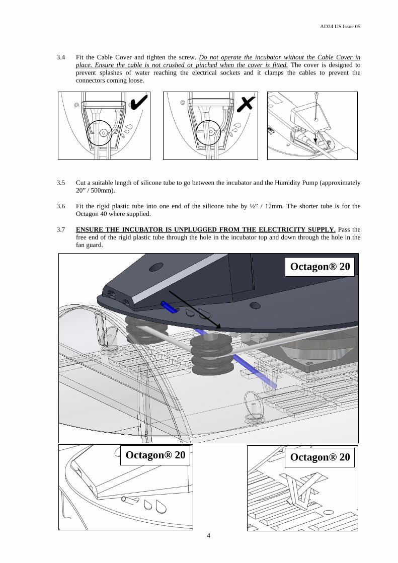
3.4 Fit the Cable Cover and tighten the screw. Do not operate the incubator without the Cable Cover in place. Ensure the cable is not crushed or pinched when the cover is fitted. The cover is designed to prevent splashes of water reaching the electrical sockets and it clamps the cables to prevent the connectors coming loose.
3.5 Cut a suitable length of silicone tube to go between the incubator and the Humidity Pump (approximately 20” / 500mm).
3.6 Fit the rigid plastic tube into one end of the silicone tube by ½” / 12mm. The shorter tube is for the Octagon 40 where supplied.
3.7 ENSURE THE INCUBATOR IS UNPLUGGED FROM THE ELECTRICITY SUPPLY. Pass the free end of the rigid plastic tube through the hole in the incubator top and down through the hole in the fan guard.
4
Octagon® 20 Octagon® 20
Octagon® 20

AD24 US Issue 05
Octagon® 40
Through hole
Through slot
Octagon® 40 Octagon® 40
5

AD24 US Issue 05
3.8 The Advance Humidity Pump is supplied with a length of silicone tube to be fitted around the pump rotor. This length will wear and need periodic replacement. It can also become flattened if left unused for some time because the inside walls of the tube will stick to each other around the rotor and prevent water passing through. Either replace this length of tube with a new 5 ½” (140mm) length or remove it and roll it between finger and thumb to ‘un-stick’ it.
3.9 Cut a 7 ½” (190mm) length of silicone tube and fit to the pump inlet hose nipple (at the right end of the pump). Pass this tube through the hole in the yellow moulding down into the water tank. Allow a loop as shown to prevent kinks.
3.10 Fit the silicone tube from the incubator to the outlet hose nipple.
Outlet Hose Nipple To incubator
140mm long
Inlet Hose Nipple
7½” long
3.11 Fold a pre-cut evaporating pad lengthways into a V shape.
3.12 OCTAGON® 20 - Place over the pad guides and then secure with the two yellow pad clips. These should be gently squeezed and fitted into the retaining slots in the fan guard as shown:-
Pad Guides Clip Slots
6

AD24 US Issue 05
3.13 OCTAGON® 40 – Tuck the pad under the three retaining hooks. Ensure the pad stays open in a V shape. Ensure the water tube is inside the V of the pad.
4 Egg Basket And Divider Cushions 4.1 Place the flat sheet of foam cushion in the bottom of the egg basket(s).
4.2 Fit the divider cushion strips inside each wire divider as shown:-
4.3 The dividers may be spaced so that eggs roll slightly between the cushions as the cradle turns the incubator. This may be useful to increase egg turning angle.
5 Operation The scope of these instructions is limited solely to the humidity control system of Brinsea® Octagon® Advance Incubators. Please read the user instructions supplied with the incubator itself for full details of all aspects of operating the incubator. NOTE: The pump will not operate if the incubator temperature is significantly below the set temperature. This prevents flooding when the lid is removed.
5.1 Fill the water tank to no higher than the bottom of the yellow moulding with clean water and fit the rubber bung in the filler hole.
5.2 Read the operating instructions supplied with the Octagon® 20 or 40 Advance Incubator for full details of how to set up and operate the incubator. Set the vent to its mid position. Refer to the “Main Menu Quick Reference” on page 3.
5.3 Open the main menu by pressing the – and + buttons simultaneously.
TEMP OK
7

AD24 US Issue 05
Press the + button once to move to the RH% option.
RH% OK
Press OK to select.
RH 20% EX ONLY
The – and + buttons may now be used to select the desired Set Humidity Level.
RH 45% EX ONLY
Once correct press OK. Scroll to the Save option using the + button and press OK to save the new humidity setting.
SAVE OK
5.4 If the humidity level in the incubator is lower than the Set Humidity Level the pump will start to turn and gradually draw water from the tank and pump it to the evaporating pad in the incubator. This may take approximately one hour to stabilise after which the pump will run intermittently as the humidity level is controlled.
5.5 The humidity level may fluctuate slightly about the Set Humidity Level by 1 or 2 %. This is quite normal. Note that the humidity control system can only increase the humidity level, not reduce it.
5.6 Guidelines for incubation humidity levels: RH During incubation: Poultry 40-50% Waterfowl 45-55% Ratites 20-35% Parrots 35-45% Most Birds of Prey 40-45% (Thin shelled - Merlins, Kestrels, Owls) 50% Hatching All species 65% RH or more
For more specific information on particular species’ requirements check the relevant literature.
5.7 To determine the correct humidity level for any given species either consult available literature (a range of bird keeping and breeding books is available from Brinsea® Products at the address below) or experiment with different humidity levels and record which proved most successful or weigh eggs during incubation. Eggs loose moisture through their shells and the rate of evaporation depends on the humidity levels around the eggs. During incubation eggs need to loose a fixed amount of water which corresponds to a loss in weight of around 13-16% depending on species. By weighing eggs periodically during incubation it is possible to monitor and, if necessary, correct humidity levels to achieve the correct weight loss. Weigh the eggs on the day they are set in the incubator, take the average weight and plot this on a graph (see example below). The ideal weight loss line can be plotted by joining the point representing initial average weight with the ideal hatch weight (13-16% less depending on species) with the x-axis representing the incubation period (in days).
By measuring actual average weights every few days the actual weight loss can be plotted and compared to the ideal weight loss line and corrections can be made. For example if the actual weight loss was greater than ideal (see graph below) then the air has been too dry and humidity levels need to be increased to compensate.
8

AD24 US Issue 05
Typical ideal weight losses for species groups: Poultry 13% Waterfowl 14%
Birds of prey 18% Ratites 15%
Parrots 16%
Egg weight loss chart
5456586062646668
1 3 5 7 9 11 13 15 17 19 21
Incubation period (days)
Ave
rage
egg
wei
ght
(gra
ms) Ideal weight (grams)
Measured weight (grams)
6 Routine Maintenance 6.1 Changing the pump tube:-
The peristaltic pump will need to have its tube replaced about every 3 months. Cut a length of tube to about 140mm. Remove the connectors and pull off the old tube. Replace with the new tube, avoiding twists. Use the diagram on the product label to thread the tube exactly as shown over the pump head. The tension must be sufficient to ensure complete occlusion of the tube without unnecessary flattening between the pump rollers. Adjust tube length as necessary. Ensure that the tube does not stick together if left for long periods by unhooking it during storage.
6.2 Changing the evaporating pad:- Change the pad as necessary to maintain good evaporating efficiency. If chicks are to be hatched in the incubator, change the pad after each hatch to avoid bacterial contamination.
6.3 No lubrication or further servicing is required beyond the instructions above.
7 Troubleshooting The control system may be set to control between 20 and 80% RH. In practice the minimum and maximum levels of humidity achievable in an incubator depend upon several factors, particularly the fresh air ventilation rate. You may need to allow 24 hours for humidity to stabilise after making changes. If you cannot get the level of RH you want, consider these notes: 7.1 Humidity will not go low enough:-
First increase the fresh air ventilation level. This will help to dilute the moisture given up by the eggs. There will still remain a lower limit determined by the moisture content of the ambient air, particularly in warm humid conditions. This can only be countered by dehumidification of the room air outside the incubator with proprietary dehumidifier but is rarely a problem in practice except with ratites.
9

AD24 US Issue 05
10
7.2 Humidity will not go high enough:-
Restrict fresh air ventilation to the minimum safe level. Remember embryos need to breathe! Increase evaporating pad area. If the pad is too small, you may have a flood in your incubator.
Check that water is reaching the incubator when the pump runs – if not check the whole length of the tubing for kinks and check that the tubing around the pump has not become permanently flattened. If it has, replace the pump tube. Silicone tubing is very flexible but can be damaged by sharp finger nails. A tiny perforation on the suction side of the pump will let in air and prevent the pump drawing water.
8 Servicing and Calibration 8.1 In case of failure first check the signal cable is securely connected to the incubator.
8.2 The pump motor will only operate when an asterisk “*” is shown next to the RH% display on the
incubator. If this is not shown check the Set Humidity Level referring to section 5. The asterisk and pump output are only on when the measured humidity is lower than the Set Humidity Level. The pump output is switched on intermittently once the measured humidity is within 6% of the Set Humidity Level.
8.3 The pump motor is easily replaced if necessary using basic tools. Instructions are supplied.
8.4 The digital humidity sensor is individually calibrated during manufacture but may be re-calibrated if required. To ensure optimal performance return the incubator to Brinsea® Products Service dept. for re-calibration every two years. It is not recommended that this procedure is carried out by the user. BE CAUTIOUS OF LOW COST ANALOGUE OR DIGITAL HYGROMETERS. BRINSEA® PRODUCTS USES SOPHISTICATED EQUIPMENT TRACEABLE TO INTERNATIONAL REFERENCE STANDARDS. Refer to the incubator instructions for details on calibration technique.
8.5 Spare evaporating pads and silicone tube are available from Brinsea® Products at the address below.
9 Specification Sensor: Sensor accuracy +/- 3%. Hysteresis 0% R.H
Response time less than 4 seconds Water Transfer: In-built peristaltic pump
Maximum water flow rate 30g/hour Tank Capacity: 34oz (1L)
Control setting and metering: Indicated in %RH
Dimensions: 5.9” (15cm) x 5.0” (12.5cm) x 5.5” (14cm) (W x D x H)
Weight (dry): 21oz (0.6 Kg)
Brinsea Products Inc., 704 N Dixie Ave., Titusville, FL 32796-2017 USA. Phone. (321) 267-7009 Toll Free 1-888-667-7009 Fax (321) 267-6090
e-mail [email protected], website www.Brinsea.com