with second generation head design - acumed
TRANSCRIPT
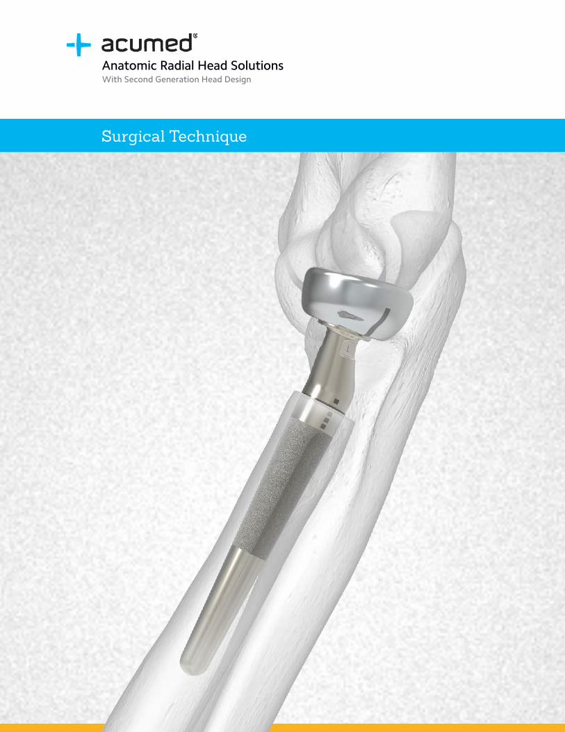
Surgical Technique
Anatomic Radial Head SolutionsWith Second Generation Head Design
Acumed® is a global leader of innovative orthopaedic and medical solutions.
We are dedicated to developing products, service methods, and approaches that improve patient care.
Definition
Warning Indicates critical information about a potential serious outcome to the patient or the user.
Caution Indicates instructions that must be followed in order to ensure the proper use of the device.
Note Indicates information requiring special attention.
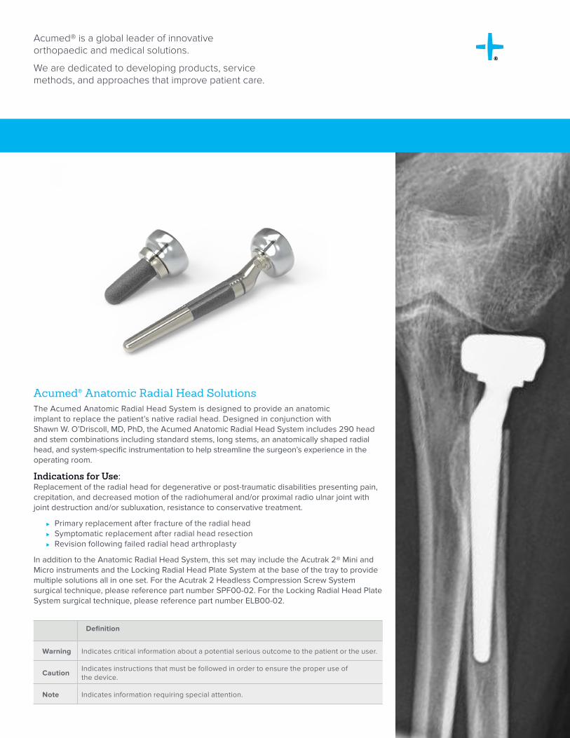
Acumed® Anatomic Radial Head SolutionsThe Acumed Anatomic Radial Head System is designed to provide an anatomic implant to replace the patient’s native radial head. Designed in conjunction with Shawn W. O’Driscoll, MD, PhD, the Acumed Anatomic Radial Head System includes 290 head and stem combinations including standard stems, long stems, an anatomically shaped radial head, and system-specific instrumentation to help streamline the surgeon’s experience in the operating room.
Indications for Use:Replacement of the radial head for degenerative or post-traumatic disabilities presenting pain, crepitation, and decreased motion of the radiohumeral and/or proximal radio ulnar joint with joint destruction and/or subluxation, resistance to conservative treatment.
⊲ Primary replacement after fracture of the radial head ⊲ Symptomatic replacement after radial head resection ⊲ Revision following failed radial head arthroplasty
In addition to the Anatomic Radial Head System, this set may include the Acutrak 2® Mini and Micro instruments and the Locking Radial Head Plate System at the base of the tray to provide multiple solutions all in one set. For the Acutrak 2 Headless Compression Screw System surgical technique, please reference part number SPF00-02. For the Locking Radial Head Plate System surgical technique, please reference part number ELB00-02.
Acumed® Anatomic Radial Head Solutions With Second Generation Head Design Surgical Technique
Table of Contents
System Features . . . . . . . . . . . . . . . . . . . . . . . . . . . . . . . . . . . . . . . . . . . . . . . . . . . . . . . . . . . . . . . . 2
Instrument Overview . . . . . . . . . . . . . . . . . . . . . . . . . . . . . . . . . . . . . . . . . . . . . . . . . . . . . . . . . . . . 6
Surgical Technique Overview . . . . . . . . . . . . . . . . . . . . . . . . . . . . . . . . . . . . . . . . . . . . . . . . . . . . . 8
Surgical Techniques . . . . . . . . . . . . . . . . . . . . . . . . . . . . . . . . . . . . . . . . . . . . . . . . . . . . . . . . . . . . 10
Anatomic Radial Head—Standard Stem . . . . . . . . . . . . . . . . . . . . . . . . . . . . . . . . . . . . . . . . 10
Anatomic Radial Head—Long Stem . . . . . . . . . . . . . . . . . . . . . . . . . . . . . . . . . . . . . . . . . . . . 16
Anatomic Radial Head and Stem Removal . . . . . . . . . . . . . . . . . . . . . . . . . . . . . . . . . . . . . . 21
Ordering Information . . . . . . . . . . . . . . . . . . . . . . . . . . . . . . . . . . . . . . . . . . . . . . . . . . . . . . . . . . .22
References . . . . . . . . . . . . . . . . . . . . . . . . . . . . . . . . . . . . . . . . . . . . . . . . . . . . . . . . . . . . . . . . . . . .28
Acumed® Anatomic Radial Head Solutions With Second Generation Head Design Surgical Technique
2
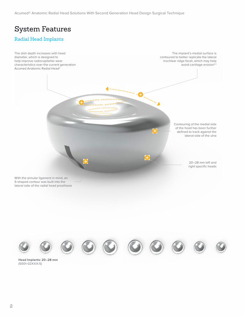
Head Implants: 20–28 mm (5001-02XXX-S)
The implant’s medial surface is contoured to better replicate the lateral
trochlear ridge facet, which may help avoid cartilage erosion1,2
The dish depth increases with head diameter, which is designed to help improve radiocapitellar wear characteristics over the current generation Acumed Anatomic Radial Head2
Contouring of the medial side of the head has been further defined to track against the
lateral side of the ulna
20–28 mm left and right specific heads
With the annular ligament in mind, an S-shaped contour was built into the lateral side of the radial head prosthesis
System FeaturesRadial Head Implants
Acumed® Anatomic Radial Head Solutions With Second Generation Head Design Surgical Technique
3
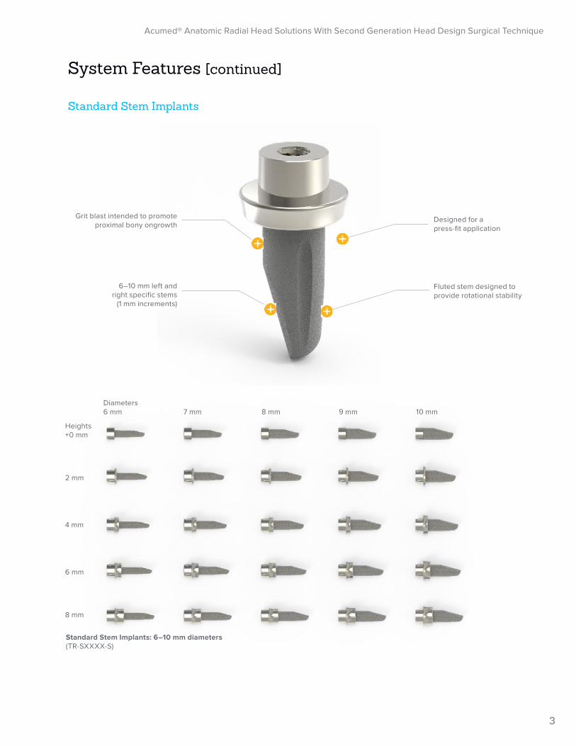
Standard Stem Implants
6–10 mm left and right specific stems
(1 mm increments)
Designed for a press-fit application
Grit blast intended to promote proximal bony ongrowth
Fluted stem designed to provide rotational stability
Standard Stem Implants: 6–10 mm diameters(TR-SXXXX-S)
System Features [continued]
Diameters6 mm 7 mm 8 mm 9 mm 10 mm
Heights+0 mm
2 mm
4 mm
6 mm
8 mm
Acumed® Anatomic Radial Head Solutions With Second Generation Head Design Surgical Technique
4
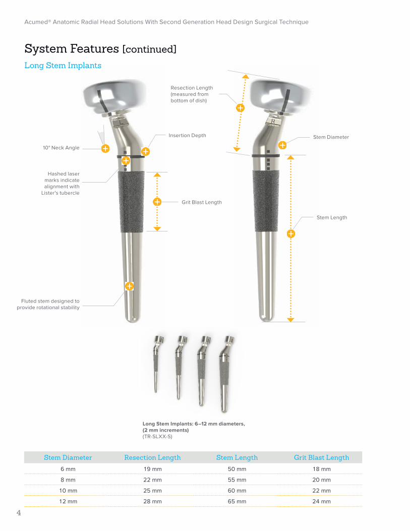
Stem Length
Stem Diameter
Grit Blast Length
10° Neck Angle
Insertion Depth
Fluted stem designed to provide rotational stability
Hashed laser marks indicate alignment with
Lister's tubercle
Stem Diameter Resection Length Stem Length Grit Blast Length
6 mm 19 mm 50 mm 18 mm
8 mm 22 mm 55 mm 20 mm
10 mm 25 mm 60 mm 22 mm
12 mm 28 mm 65 mm 24 mm
Resection Length(measured from bottom of dish)
System Features [continued]Long Stem Implants
Long Stem Implants: 6–12 mm diameters, (2 mm increments)(TR-SLXX-S)
Acumed® Anatomic Radial Head Solutions With Second Generation Head Design Surgical Technique
5
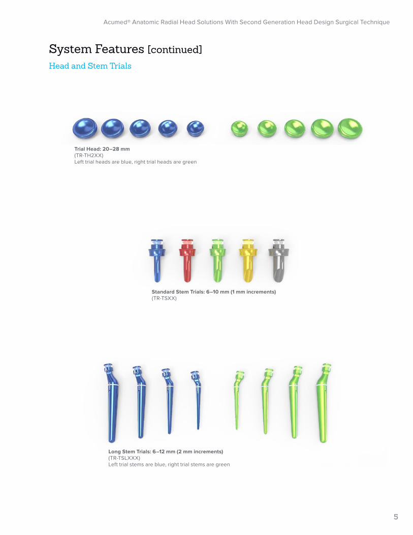
Standard Stem Trials: 6–10 mm (1 mm increments)(TR-TSXX)
Long Stem Trials: 6–12 mm (2 mm increments)(TR-TSLXXX)Left trial stems are blue, right trial stems are green
Trial Head: 20–28 mm (TR-TH2XX)Left trial heads are blue, right trial heads are green
System Features [continued]Head and Stem Trials
Acumed® Anatomic Radial Head Solutions With Second Generation Head Design Surgical Technique
6
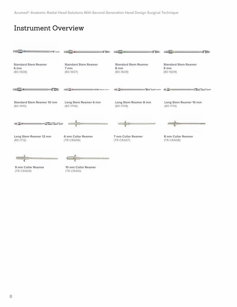
Standard Stem Reamer 6 mm(80-1606)
Standard Stem Reamer 7 mm(80-1607)
Standard Stem Reamer 8 mm(80-1608)
Standard Stem Reamer 9 mm(80-1609)
Standard Stem Reamer 10 mm(80-1610)
Long Stem Reamer 6 mm(80-1706)
Long Stem Reamer 8 mm(80-1708)
Long Stem Reamer 10 mm(80-1710)
Long Stem Reamer 12 mm(80-1712)
6 mm Collar Reamer(TR-CRA06)
7 mm Collar Reamer(TR-CRA07)
8 mm Collar Reamer(TR-CRA08)
9 mm Collar Reamer(TR-CRA09)
10 mm Collar Reamer(TR-CRA10)
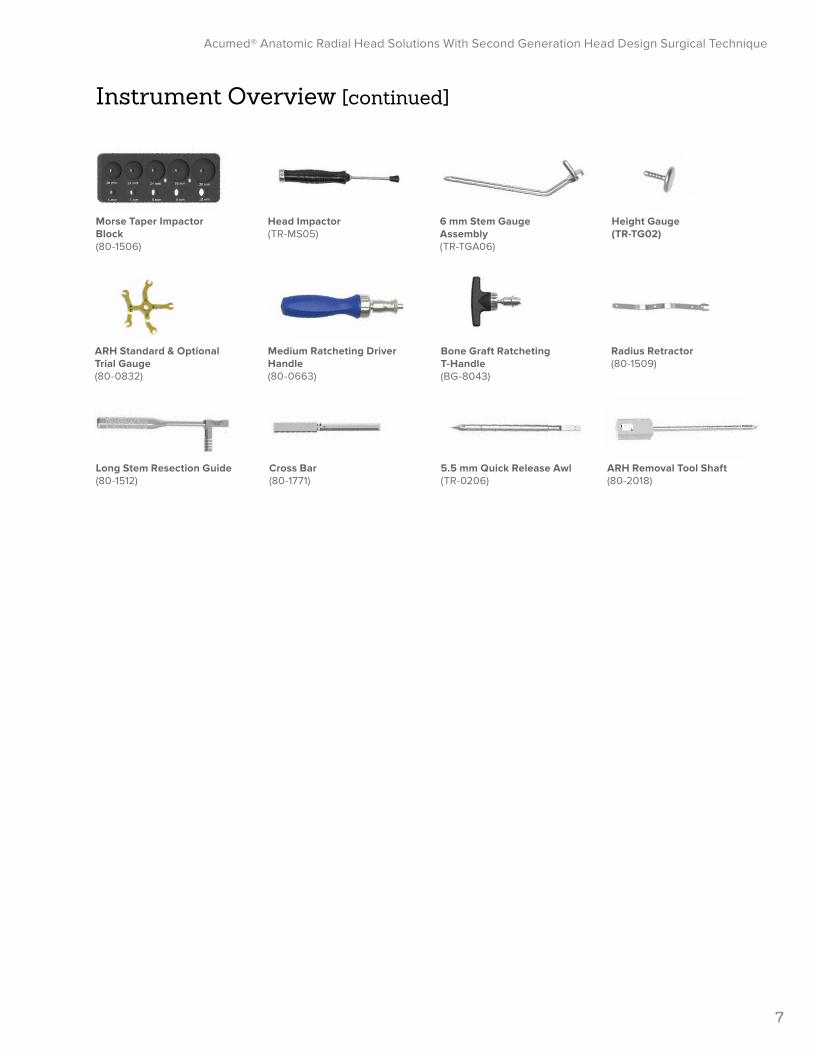
Instrument Overview
Acumed® Anatomic Radial Head Solutions With Second Generation Head Design Surgical Technique
7
Bone Graft Ratcheting T-Handle(BG-8043)
Cross Bar(80-1771)
Long Stem Resection Guide(80-1512)
Radius Retractor(80-1509)
5.5 mm Quick Release Awl(TR-0206)
ARH Removal Tool Shaft (80-2018)
Head Impactor(TR-MS05)
6 mm Stem Gauge Assembly(TR-TGA06)
Height Gauge (TR-TG02)
ARH Standard & Optional Trial Gauge (80-0832)
Medium Ratcheting Driver Handle (80-0663)
Morse Taper Impactor Block(80-1506)
Instrument Overview [continued]
Acumed® Anatomic Radial Head Solutions With Second Generation Head Design Surgical Technique
8
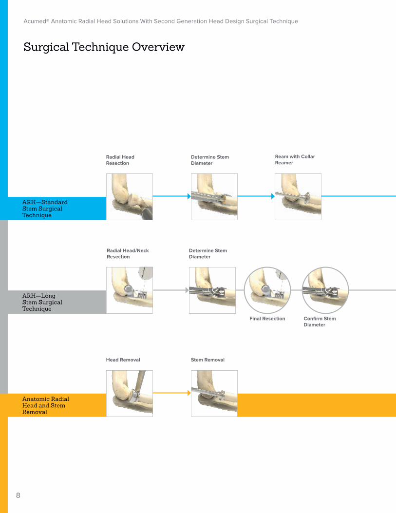
Surgical Technique Overview
Anatomic Radial Head and Stem Removal
ARH—Long Stem Surgical Technique
ARH—Standard Stem Surgical Technique
Determine Stem Diameter
Stem Removal
Ream with Collar Reamer
Radial Head Resection
Head Removal
Determine Stem Diameter
Confirm Stem Diameter
Final Resection
Radial Head/Neck Resection
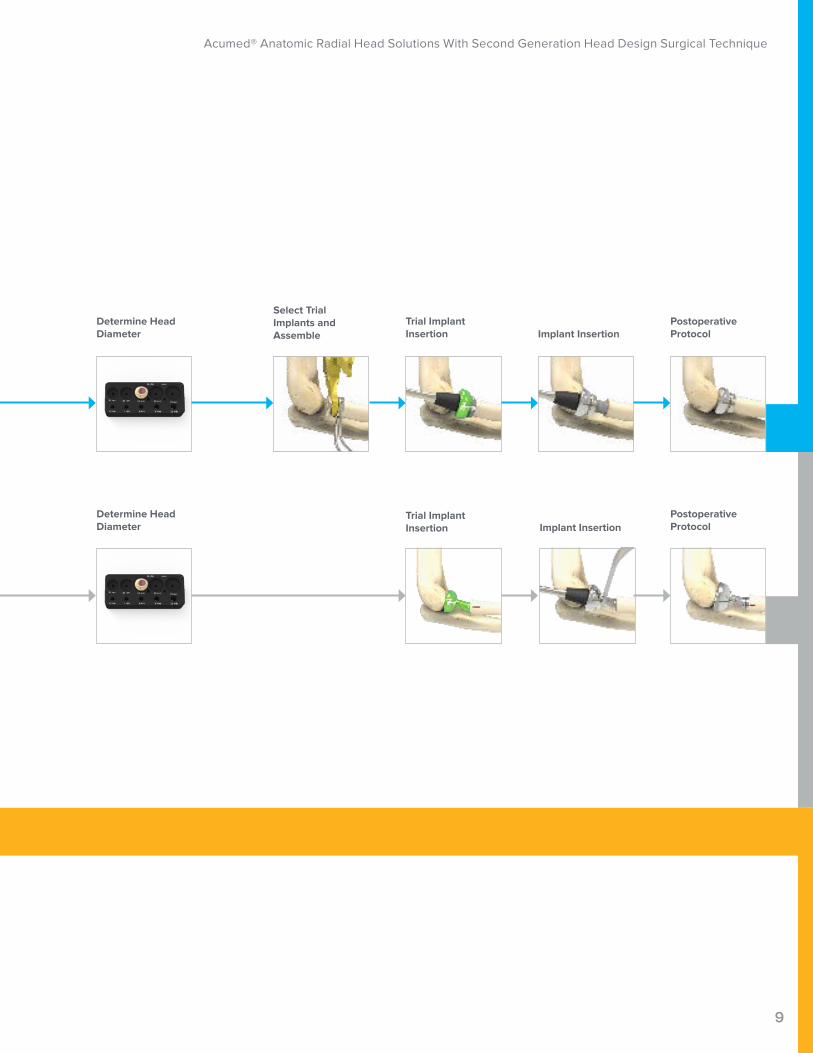
Acumed® Anatomic Radial Head Solutions With Second Generation Head Design Surgical Technique
9
Determine Head Diameter
Determine Head Diameter
Select Trial Implants and Assemble
Trial Implant Insertion
Trial Implant Insertion
Postoperative Protocol
Postoperative Protocol
Implant Insertion
Implant Insertion
Acumed® Anatomic Radial Head Solutions With Second Generation Head Design Surgical Technique
10
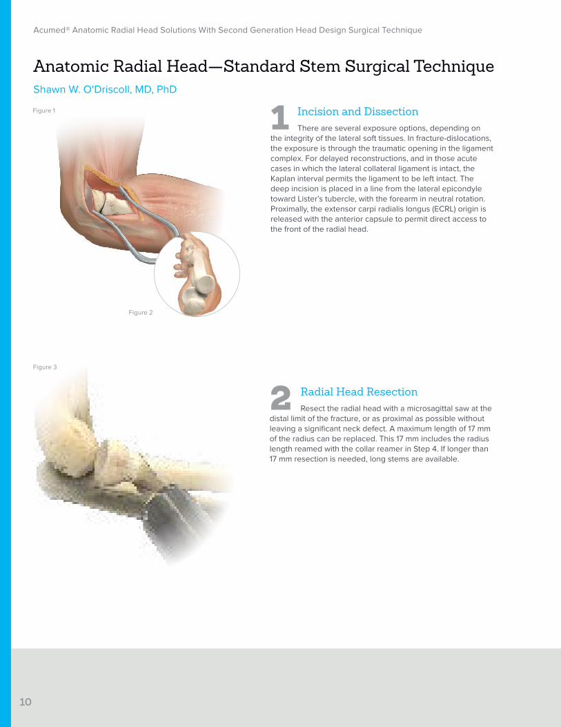
Figure 1 1 Incision and DissectionThere are several exposure options, depending on
the integrity of the lateral soft tissues. In fracture-dislocations, the exposure is through the traumatic opening in the ligament complex. For delayed reconstructions, and in those acute cases in which the lateral collateral ligament is intact, the Kaplan interval permits the ligament to be left intact. The deep incision is placed in a line from the lateral epicondyle toward Lister’s tubercle, with the forearm in neutral rotation. Proximally, the extensor carpi radialis longus (ECRL) origin is released with the anterior capsule to permit direct access to the front of the radial head.
Anatomic Radial Head—Standard Stem Surgical TechniqueShawn W. O'Driscoll, MD, PhD
2 Radial Head ResectionResect the radial head with a microsagittal saw at the
distal limit of the fracture, or as proximal as possible without leaving a significant neck defect. A maximum length of 17 mm of the radius can be replaced. This 17 mm includes the radius length reamed with the collar reamer in Step 4. If longer than 17 mm resection is needed, long stems are available.
Figure 2
Figure 3
Acumed® Anatomic Radial Head Solutions With Second Generation Head Design Surgical Technique
11
5.5 mm Quick Release Awl (TR-0206)
Bone Graft Ratcheting T-Handle (BG-8043)
Standard Stem Reamer 6 mm (80-1606)
Radius Retractor(80-1509)
Collar Reamer(TR-CRAXX)
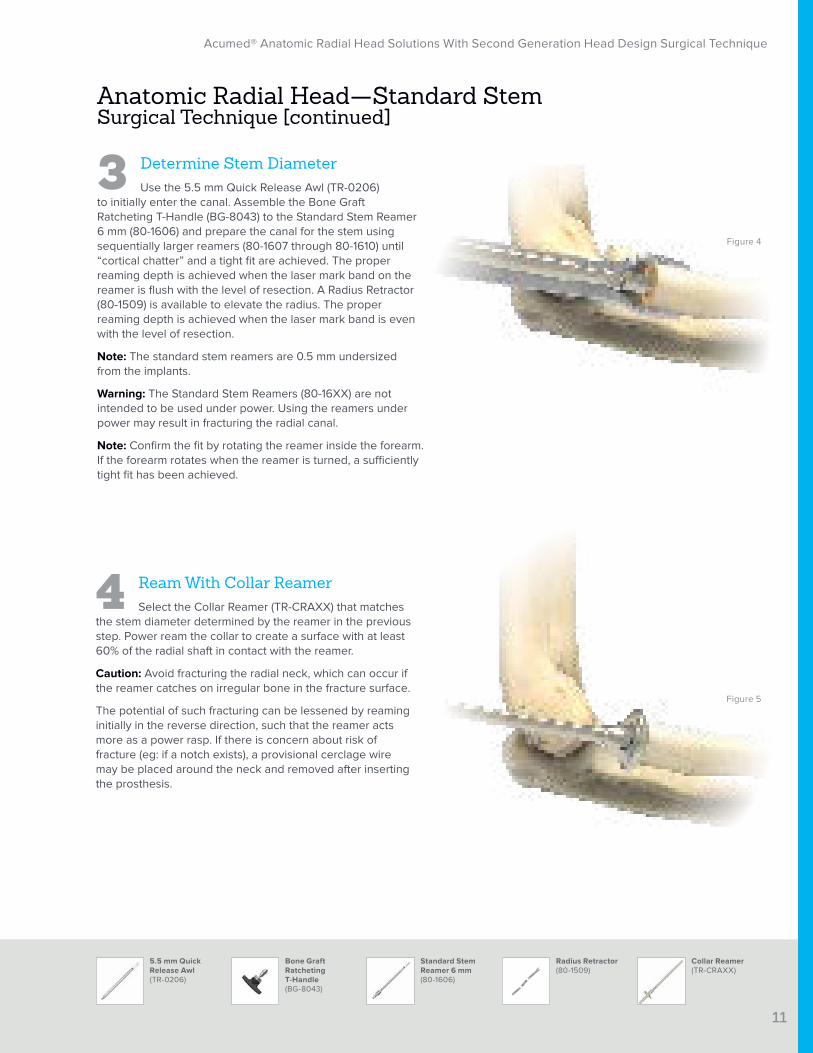
3 Determine Stem DiameterUse the 5.5 mm Quick Release Awl (TR-0206)
to initially enter the canal. Assemble the Bone Graft Ratcheting T-Handle (BG-8043) to the Standard Stem Reamer 6 mm (80-1606) and prepare the canal for the stem using sequentially larger reamers (80-1607 through 80-1610) until “cortical chatter” and a tight fit are achieved. The proper reaming depth is achieved when the laser mark band on the reamer is flush with the level of resection. A Radius Retractor (80-1509) is available to elevate the radius. The proper reaming depth is achieved when the laser mark band is even with the level of resection.
Note: The standard stem reamers are 0.5 mm undersized from the implants.
Warning: The Standard Stem Reamers (80-16XX) are not intended to be used under power. Using the reamers under power may result in fracturing the radial canal.
Note: Confirm the fit by rotating the reamer inside the forearm. If the forearm rotates when the reamer is turned, a sufficiently tight fit has been achieved.
4 Ream With Collar ReamerSelect the Collar Reamer (TR-CRAXX) that matches
the stem diameter determined by the reamer in the previous step. Power ream the collar to create a surface with at least 60% of the radial shaft in contact with the reamer.
Caution: Avoid fracturing the radial neck, which can occur if the reamer catches on irregular bone in the fracture surface.
The potential of such fracturing can be lessened by reaming initially in the reverse direction, such that the reamer acts more as a power rasp. If there is concern about risk of fracture (eg: if a notch exists), a provisional cerclage wire may be placed around the neck and removed after inserting the prosthesis.
Figure 4
Figure 5
Anatomic Radial Head—Standard Stem Surgical Technique [continued]
Acumed® Anatomic Radial Head Solutions With Second Generation Head Design Surgical Technique
12
Morse Taper Impactor Block(80-1506)
Height Gauge (TR-TG02)
6.0 mm Stem Gauge Assembly(TR-TGA06)
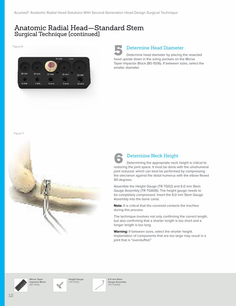
5 Determine Head DiameterDetermine head diameter by placing the resected
head upside down in the sizing pockets on the Morse Taper Impactor Block (80-1506). If between sizes, select the smaller diameter.
6 Determine Neck HeightDetermining the appropriate neck height is critical to
restoring the joint space. It must be done with the ulnohumeral joint reduced, which can best be performed by compressing the olecranon against the distal humerus with the elbow flexed 90 degrees.
Assemble the Height Gauge (TR-TG02) and 6.0 mm Stem Gauge Assembly (TR-TGA06). The height gauge needs to be completely compressed. Insert the 6.0 mm Stem Gauge Assembly into the bone canal.
Note: It is critical that the coronoid contacts the trochlea during this process.
The technique involves not only confirming the correct length, but also confirming that a shorter length is too short and a longer length is too long.
Warning: If between sizes, select the shorter height. Implantation of components that are too large may result in a joint that is "overstuffed."
Anatomic Radial Head—Standard Stem Surgical Technique [continued]
Figure 6
Figure 7
Acumed® Anatomic Radial Head Solutions With Second Generation Head Design Surgical Technique
13
ARH Standard & Optional Trial Gauge (80-0832)
Trial Head (TR-TH2XX)
6.0 mm Stem Gauge Assembly(TR-TGA06)
Standard Stem Trials(TR-TSXX)
Height Gauge (TR-TG02)
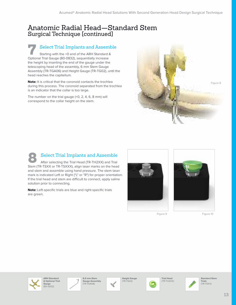
7 Select Trial Implants and AssembleStarting with the +0 end of the ARH Standard &
Optional Trial Gauge (80-0832), sequentially increase the height by inserting the end of the gauge under the telescoping head of the assembly, 6 mm Stem Gauge Assembly (TR-TGA06) and Height Gauge (TR-TG02), until the head reaches the capitellum.
Note: It is critical that the coronoid contacts the trochlea during this process. The coronoid separated from the trochlea is an indicator that the collar is too large.
The number on the trial gauge (+0, 2, 4, 6, 8 mm) will correspond to the collar height on the stem.
8 Select Trial Implants and AssembleAfter selecting the Trial Head (TR-TH2XX) and Trial
Stem (TR-TSXX or TR-TSXXX), align laser marks on the head and stem and assemble using hand pressure. The stem laser mark is indicated Left or Right ("L" or "R") for proper orientation. If the trial head and stem are difficult to connect, apply saline solution prior to connecting.
Note: Left-specific trials are blue and right-specific trials are green.
Anatomic Radial Head—Standard Stem Surgical Technique [continued]
Figure 8
Figure 9 Figure 10
Central ridge of the coronoid
Lateral edge of the coronoid
Acumed® Anatomic Radial Head Solutions With Second Generation Head Design Surgical Technique
14
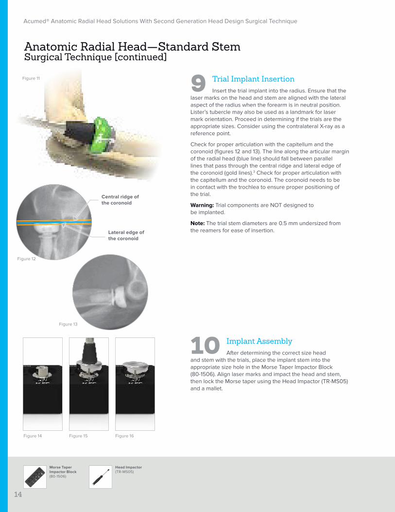
9 Trial Implant InsertionInsert the trial implant into the radius. Ensure that the
laser marks on the head and stem are aligned with the lateral aspect of the radius when the forearm is in neutral position. Lister’s tubercle may also be used as a landmark for laser mark orientation. Proceed in determining if the trials are the appropriate sizes. Consider using the contralateral X-ray as a reference point.
Check for proper articulation with the capitellum and the coronoid (figures 12 and 13). The line along the articular margin of the radial head (blue line) should fall between parallel lines that pass through the central ridge and lateral edge of the coronoid (gold lines).3 Check for proper articulation with the capitellum and the coronoid. The coronoid needs to be in contact with the trochlea to ensure proper positioning of the trial.
Warning: Trial components are NOT designed to be implanted.
Note: The trial stem diameters are 0.5 mm undersized from the reamers for ease of insertion.
10 Implant AssemblyAfter determining the correct size head
and stem with the trials, place the implant stem into the appropriate size hole in the Morse Taper Impactor Block (80-1506). Align laser marks and impact the head and stem, then lock the Morse taper using the Head Impactor (TR-MS05) and a mallet.
Anatomic Radial Head—Standard Stem Surgical Technique [continued]
Figure 11
Figure 12
Figure 13
Head Impactor(TR-MS05)
Figure 14 Figure 15 Figure 16
Morse Taper Impactor Block(80-1506)
Central ridge of the coronoid
Lateral edge of the coronoid
Acumed® Anatomic Radial Head Solutions With Second Generation Head Design Surgical Technique
15
ARH Removal Tool Shaft(80-2018)
12 Postoperative Protocol
Note: The following protocol may be replaced with an alternative protocol at the performing surgeon’s discretion.
Postoperative management is determined by the overall management of the elbow and limb, as though the radial head had never been fractured. For isolated fractures of the radial head and neck without ligament injury, early motion is commenced in flexion and extension as well as pronation and supination. This usually begins within the first few days after surgery.
Note: An ARH Removal Tool Shaft (80-2018) is available in the system for stem removal if needed. For removal instructions, reference the Anatomic Radial Head and Stem Removal technique on page 21.
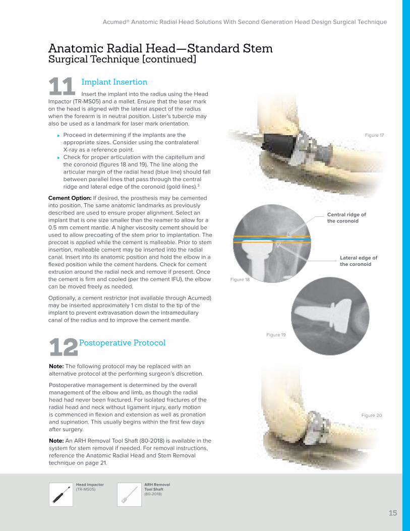
11 Implant InsertionInsert the implant into the radius using the Head
Impactor (TR-MS05) and a mallet. Ensure that the laser mark on the head is aligned with the lateral aspect of the radius when the forearm is in neutral position. Lister’s tubercle may also be used as a landmark for laser mark orientation.
⊲ Proceed in determining if the implants are the appropriate sizes. Consider using the contralateral X-ray as a reference point.
⊲ Check for proper articulation with the capitellum and the coronoid (figures 18 and 19). The line along the articular margin of the radial head (blue line) should fall between parallel lines that pass through the central ridge and lateral edge of the coronoid (gold lines).3
Cement Option: If desired, the prosthesis may be cemented into position. The same anatomic landmarks as previously described are used to ensure proper alignment. Select an implant that is one size smaller than the reamer to allow for a 0.5 mm cement mantle. A higher viscosity cement should be used to allow precoating of the stem prior to implantation. The precoat is applied while the cement is malleable. Prior to stem insertion, malleable cement may be inserted into the radial canal. Insert into its anatomic position and hold the elbow in a flexed position while the cement hardens. Check for cement extrusion around the radial neck and remove if present. Once the cement is firm and cooled (per the cement IFU), the elbow can be moved freely as needed.
Optionally, a cement restrictor (not available through Acumed) may be inserted approximately 1 cm distal to the tip of the implant to prevent extravasation down the intramedullary canal of the radius and to improve the cement mantle.
Anatomic Radial Head—Standard Stem Surgical Technique [continued]
Head Impactor(TR-MS05)
Figure 17
Figure 18
Figure 19
Figure 20
Acumed® Anatomic Radial Head Solutions With Second Generation Head Design Surgical Technique
16
ARH Removal Tool Shaft (80-2018)
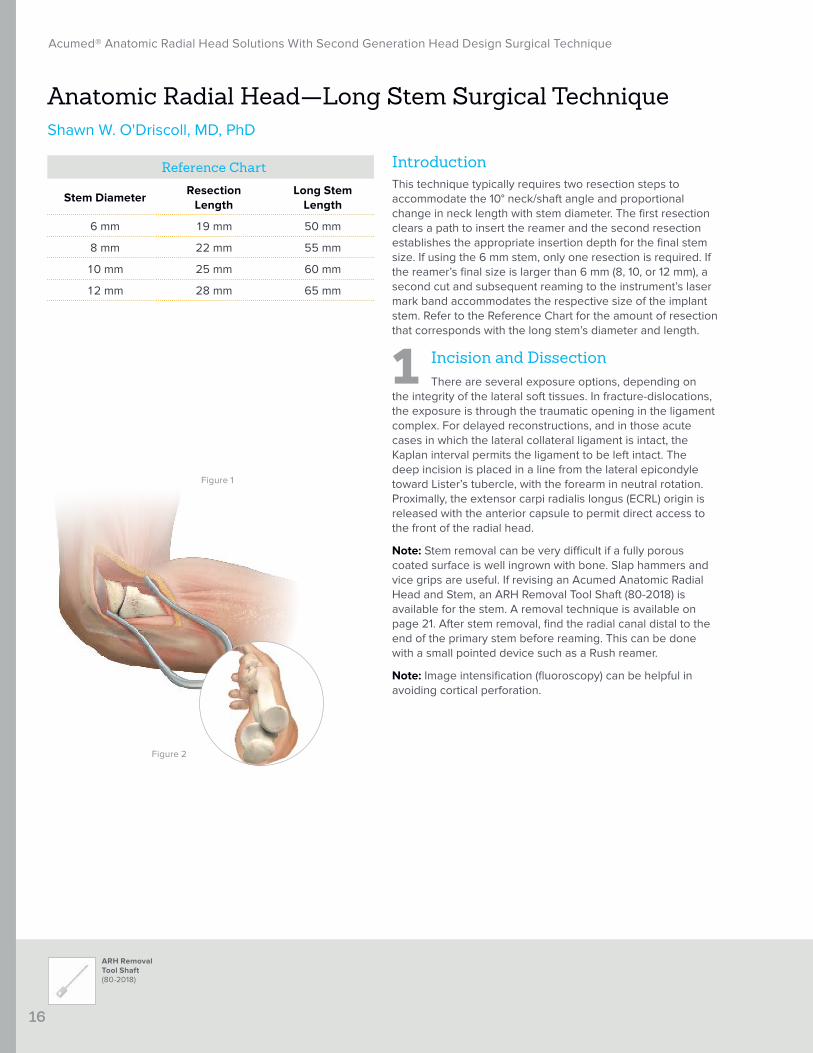
IntroductionThis technique typically requires two resection steps to accommodate the 10° neck/shaft angle and proportional change in neck length with stem diameter. The first resection clears a path to insert the reamer and the second resection establishes the appropriate insertion depth for the final stem size. If using the 6 mm stem, only one resection is required. If the reamer’s final size is larger than 6 mm (8, 10, or 12 mm), a second cut and subsequent reaming to the instrument’s laser mark band accommodates the respective size of the implant stem. Refer to the Reference Chart for the amount of resection that corresponds with the long stem’s diameter and length.
1 Incision and DissectionThere are several exposure options, depending on
the integrity of the lateral soft tissues. In fracture-dislocations, the exposure is through the traumatic opening in the ligament complex. For delayed reconstructions, and in those acute cases in which the lateral collateral ligament is intact, the Kaplan interval permits the ligament to be left intact. The deep incision is placed in a line from the lateral epicondyle toward Lister’s tubercle, with the forearm in neutral rotation. Proximally, the extensor carpi radialis longus (ECRL) origin is released with the anterior capsule to permit direct access to the front of the radial head.
Note: Stem removal can be very difficult if a fully porous coated surface is well ingrown with bone. Slap hammers and vice grips are useful. If revising an Acumed Anatomic Radial Head and Stem, an ARH Removal Tool Shaft (80-2018) is available for the stem. A removal technique is available on page 21. After stem removal, find the radial canal distal to the end of the primary stem before reaming. This can be done with a small pointed device such as a Rush reamer.
Note: Image intensification (fluoroscopy) can be helpful in avoiding cortical perforation.
Anatomic Radial Head—Long Stem Surgical TechniqueShawn W. O'Driscoll, MD, PhD
Figure 1
Figure 2
Reference Chart
Stem DiameterResection
LengthLong Stem
Length
6 mm 19 mm 50 mm
8 mm 22 mm 55 mm
10 mm 25 mm 60 mm
12 mm 28 mm 65 mm
Acumed® Anatomic Radial Head Solutions With Second Generation Head Design Surgical Technique
17
Long Stem Resection Guide(80-1512)
Osteotomy Saw Blade Hub Style L or S (80-0739-S or 80-0740-S)
Radius Retractor (80-1509)
5.5 mm Quick Release Awl(TR-0206)
Long Stem Reamers(80-17XX)
Anatomic Radial Head—Long Stem Surgical Technique [continued]
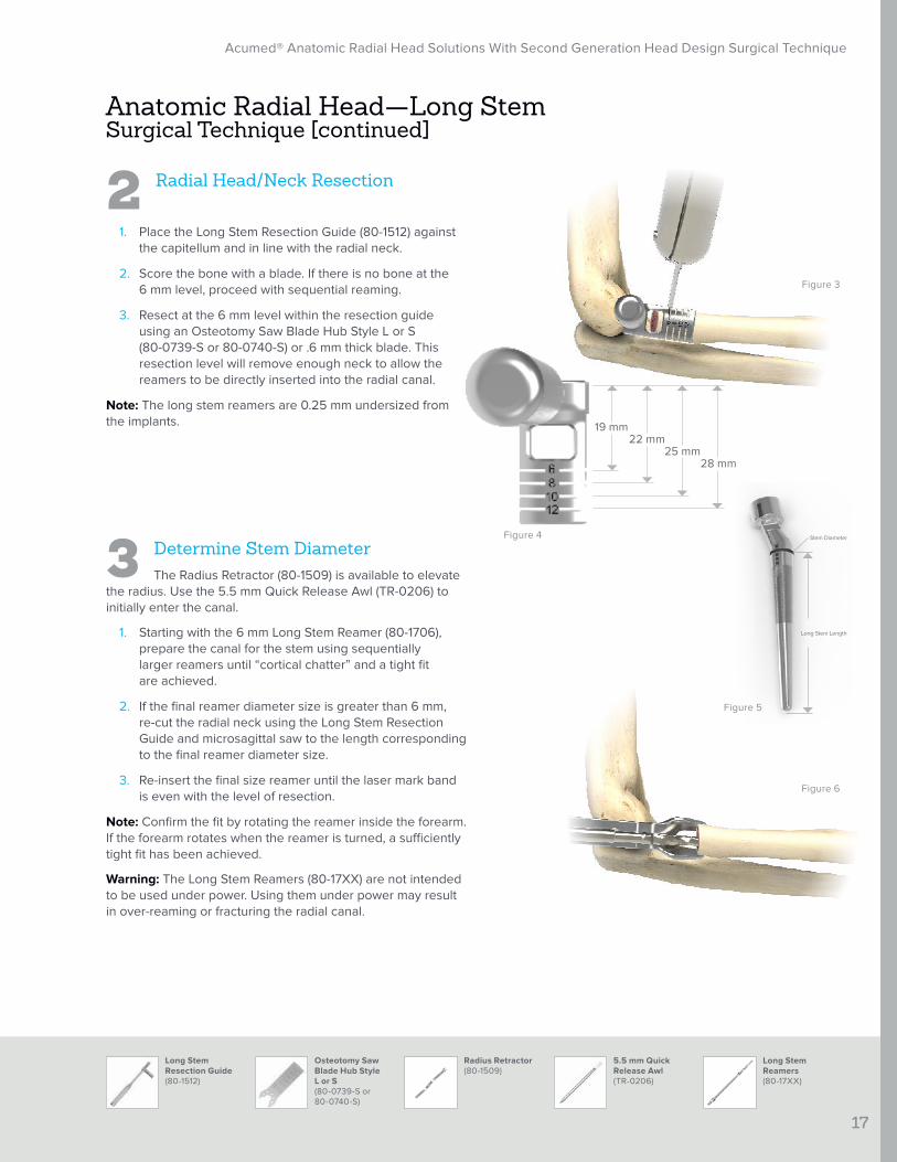
2 Radial Head/Neck Resection
1. Place the Long Stem Resection Guide (80-1512) against the capitellum and in line with the radial neck.
2. Score the bone with a blade. If there is no bone at the 6 mm level, proceed with sequential reaming.
3. Resect at the 6 mm level within the resection guide using an Osteotomy Saw Blade Hub Style L or S (80-0739-S or 80-0740-S) or .6 mm thick blade. This resection level will remove enough neck to allow the reamers to be directly inserted into the radial canal.
Note: The long stem reamers are 0.25 mm undersized from the implants.
3 Determine Stem DiameterThe Radius Retractor (80-1509) is available to elevate
the radius. Use the 5.5 mm Quick Release Awl (TR-0206) to initially enter the canal.
1. Starting with the 6 mm Long Stem Reamer (80-1706), prepare the canal for the stem using sequentially larger reamers until “cortical chatter” and a tight fit are achieved.
2. If the final reamer diameter size is greater than 6 mm, re-cut the radial neck using the Long Stem Resection Guide and microsagittal saw to the length corresponding to the final reamer diameter size.
3. Re-insert the final size reamer until the laser mark band is even with the level of resection.
Note: Confirm the fit by rotating the reamer inside the forearm. If the forearm rotates when the reamer is turned, a sufficiently tight fit has been achieved.
Warning: The Long Stem Reamers (80-17XX) are not intended to be used under power. Using them under power may result in over-reaming or fracturing the radial canal.
Figure 3
Figure 4
Figure 6
Long Stem Length
Stem Diameter
28 mm25 mm
22 mm19 mm
Figure 5
Acumed® Anatomic Radial Head Solutions With Second Generation Head Design Surgical Technique
18
Trial Head (TR-TH2XX)
Trial Morse Taper Long Stem (TR-TSLXXX)
Morse Taper Impactor Block(80-1506)
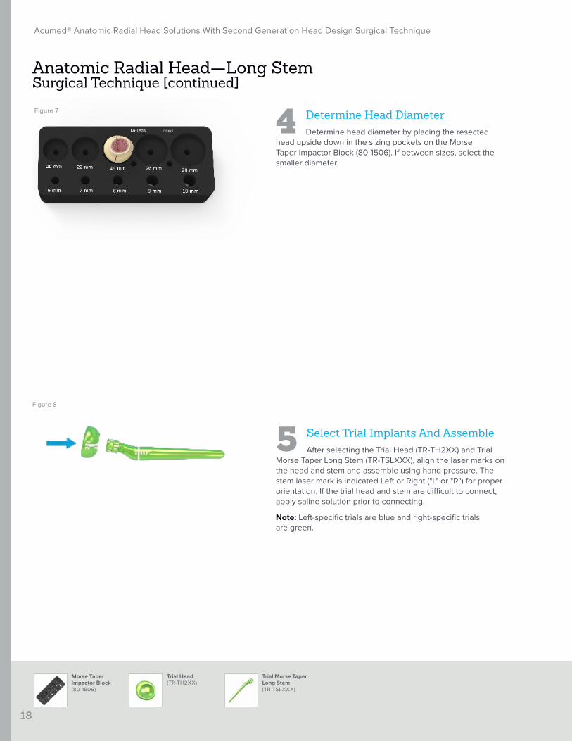
4 Determine Head DiameterDetermine head diameter by placing the resected
head upside down in the sizing pockets on the Morse Taper Impactor Block (80-1506). If between sizes, select the smaller diameter.
5 Select Trial Implants And AssembleAfter selecting the Trial Head (TR-TH2XX) and Trial
Morse Taper Long Stem (TR-TSLXXX), align the laser marks on the head and stem and assemble using hand pressure. The stem laser mark is indicated Left or Right ("L" or "R") for proper orientation. If the trial head and stem are difficult to connect, apply saline solution prior to connecting.
Note: Left-specific trials are blue and right-specific trials are green.
Anatomic Radial Head—Long Stem Surgical Technique [continued]
Figure 7
Figure 8
Acumed® Anatomic Radial Head Solutions With Second Generation Head Design Surgical Technique
19
Morse Taper Long Stem Alignment Guide (80-2127)
Morse Taper Impactor Block (80-1506)
Head Impactor (TR-MS05)
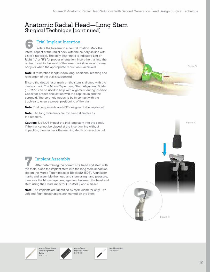
6 Trial Implant InsertionRotate the forearm to a neutral rotation. Mark the
lateral aspect of the radial neck with the cautery (in line with Lister’s tubercle). The stem laser mark is indicated Left or Right ("L" or "R") for proper orientation. Insert the trial into the radius. Insert to the level of the laser mark (line around stem body) or when the appropriate reduction is achieved.
Note: If restoration length is too long, additional reaming and reinsertion of the trial is suggested.
Ensure the dotted laser mark on the stem is aligned with the cautery mark. The Morse Taper Long Stem Alignment Guide (80-2127) can be used to help with alignment during insertion. Check for proper articulation with the capitellum and the coronoid. The coronoid needs to be in contact with the trochlea to ensure proper positioning of the trial.
Note: Trial components are NOT designed to be implanted.
Note: The long stem trials are the same diameter as the reamers.
Caution: Do NOT impact the trial long stem into the canal. If the trial cannot be placed at the insertion line without impaction, then recheck the reaming depth or resection cut.
7 Implant AssemblyAfter determining the correct size head and stem with
the trials, place the implant stem into the long stem impaction site on the Morse Taper Impactor Block (80-1506). Align laser marks and assemble the head and stem using hand pressure, then lock the Morse taper engagement between the head and stem using the Head Impactor (TR-MS05) and a mallet.
Note: The implants are identified by stem diameter only. The Left and Right designations are marked on the stem.
Anatomic Radial Head—Long Stem Surgical Technique [continued]
Figure 9
Figure 10
Figure 11
Acumed® Anatomic Radial Head Solutions With Second Generation Head Design Surgical Technique
20
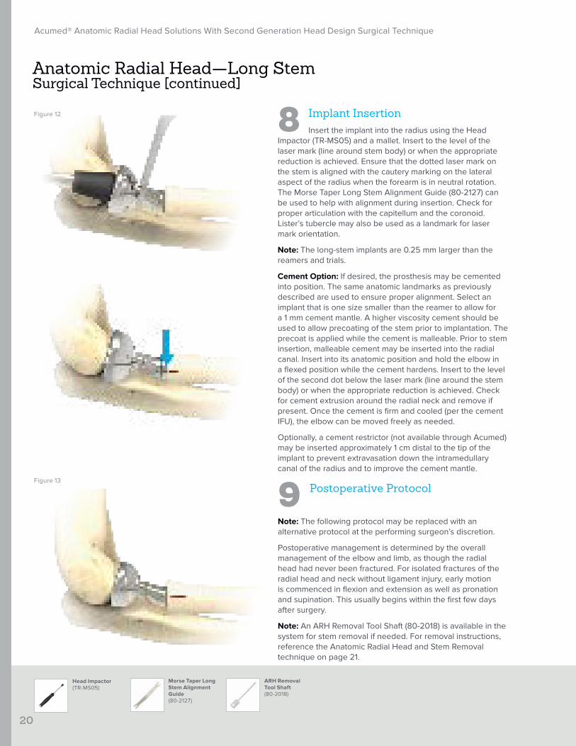
9 Postoperative Protocol
Note: The following protocol may be replaced with an alternative protocol at the performing surgeon’s discretion.
Postoperative management is determined by the overall management of the elbow and limb, as though the radial head had never been fractured. For isolated fractures of the radial head and neck without ligament injury, early motion is commenced in flexion and extension as well as pronation and supination. This usually begins within the first few days after surgery.
Note: An ARH Removal Tool Shaft (80-2018) is available in the system for stem removal if needed. For removal instructions, reference the Anatomic Radial Head and Stem Removal technique on page 21.
8 Implant InsertionInsert the implant into the radius using the Head
Impactor (TR-MS05) and a mallet. Insert to the level of the laser mark (line around stem body) or when the appropriate reduction is achieved. Ensure that the dotted laser mark on the stem is aligned with the cautery marking on the lateral aspect of the radius when the forearm is in neutral rotation. The Morse Taper Long Stem Alignment Guide (80-2127) can be used to help with alignment during insertion. Check for proper articulation with the capitellum and the coronoid. Lister’s tubercle may also be used as a landmark for laser mark orientation.
Note: The long-stem implants are 0.25 mm larger than the reamers and trials.
Cement Option: If desired, the prosthesis may be cemented into position. The same anatomic landmarks as previously described are used to ensure proper alignment. Select an implant that is one size smaller than the reamer to allow for a 1 mm cement mantle. A higher viscosity cement should be used to allow precoating of the stem prior to implantation. The precoat is applied while the cement is malleable. Prior to stem insertion, malleable cement may be inserted into the radial canal. Insert into its anatomic position and hold the elbow in a flexed position while the cement hardens. Insert to the level of the second dot below the laser mark (line around the stem body) or when the appropriate reduction is achieved. Check for cement extrusion around the radial neck and remove if present. Once the cement is firm and cooled (per the cement IFU), the elbow can be moved freely as needed.
Optionally, a cement restrictor (not available through Acumed) may be inserted approximately 1 cm distal to the tip of the implant to prevent extravasation down the intramedullary canal of the radius and to improve the cement mantle.
Anatomic Radial Head—Long Stem Surgical Technique [continued]
Figure 12
Figure 13
Morse Taper Long Stem Alignment Guide (80-2127)
ARH Removal Tool Shaft (80-2018)
Head Impactor (TR-MS05)
Acumed® Anatomic Radial Head Solutions With Second Generation Head Design Surgical Technique
21
ARH Removal Tool Shaft (80-2018)
Cross Bar(80-1771)
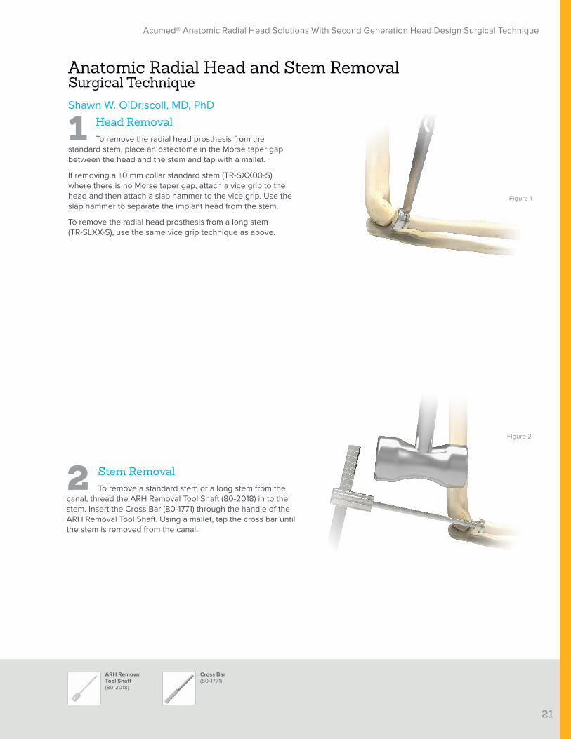
1 Head RemovalTo remove the radial head prosthesis from the
standard stem, place an osteotome in the Morse taper gap between the head and the stem and tap with a mallet.
If removing a +0 mm collar standard stem (TR-SXX00-S) where there is no Morse taper gap, attach a vice grip to the head and then attach a slap hammer to the vice grip. Use the slap hammer to separate the implant head from the stem.
To remove the radial head prosthesis from a long stem (TR-SLXX-S), use the same vice grip technique as above.
Anatomic Radial Head and Stem Removal Surgical TechniqueShawn W. O'Driscoll, MD, PhD
2 Stem RemovalTo remove a standard stem or a long stem from the
canal, thread the ARH Removal Tool Shaft (80-2018) in to the stem. Insert the Cross Bar (80-1771) through the handle of the ARH Removal Tool Shaft. Using a mallet, tap the cross bar until the stem is removed from the canal.
Figure 1
Figure 2

Acumed® Anatomic Radial Head Solutions With Second Generation Head Design Surgical Technique
22
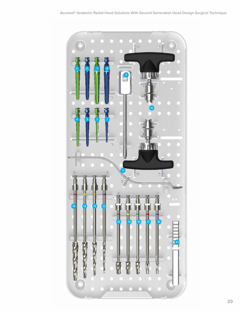
Ordering InformationTray Components
Long Stem Trials Instruments
1 6 mm Trial Morse Taper Long Stem, Left TR-TSL06L 9 ARH Removal Tool Shaft 80-2018
2 6 mm Trial Morse Taper Long Stem, Right TR-TSL06R 10 Bone Graft Ratcheting T-Handle BG-8043
3 8 mm Trial Morse Taper Long Stem, Left TR-TSL08L 11 Radius Retractor 80-1509
4 8 mm Trial Morse Taper Long Stem, Right TR-TSL08R 12 Long Stem Reamer 6 mm 80-1706
5 10 mm Trial Morse Taper Long Stem, Left TR-TSL10L 13 Long Stem Reamer 8 mm 80-1708
6 10 mm Trial Morse Taper Long Stem, Right TR-TSL10R 14 Long Stem Reamer 10 mm 80-1710
7 12 mm Trial Morse Taper Long Stem, Left TR-TSL12L 15 Long Stem Reamer 12 mm 80-1712
8 12 mm Trial Morse Taper Long Stem, Right TR-TSL12R 16 Standard Stem Reamer 6 mm 80-1606
17 Standard Stem Reamer 7 mm 80-1607
18 Standard Stem Reamer 8 mm 80-1608
19 Standard Stem Reamer 9 mm 80-1609
20 Standard Stem Reamer 10 mm 80-1610
21 Cross Bar 80-1771
1
Acumed® Anatomic Radial Head Solutions With Second Generation Head Design Surgical Technique
23
5
4
6
3
7
2
8
1
9
10
11
1415 13 12
20 19 18 17 16
21
Acumed® Anatomic Radial Head Solutions With Second Generation Head Design Surgical Technique
24
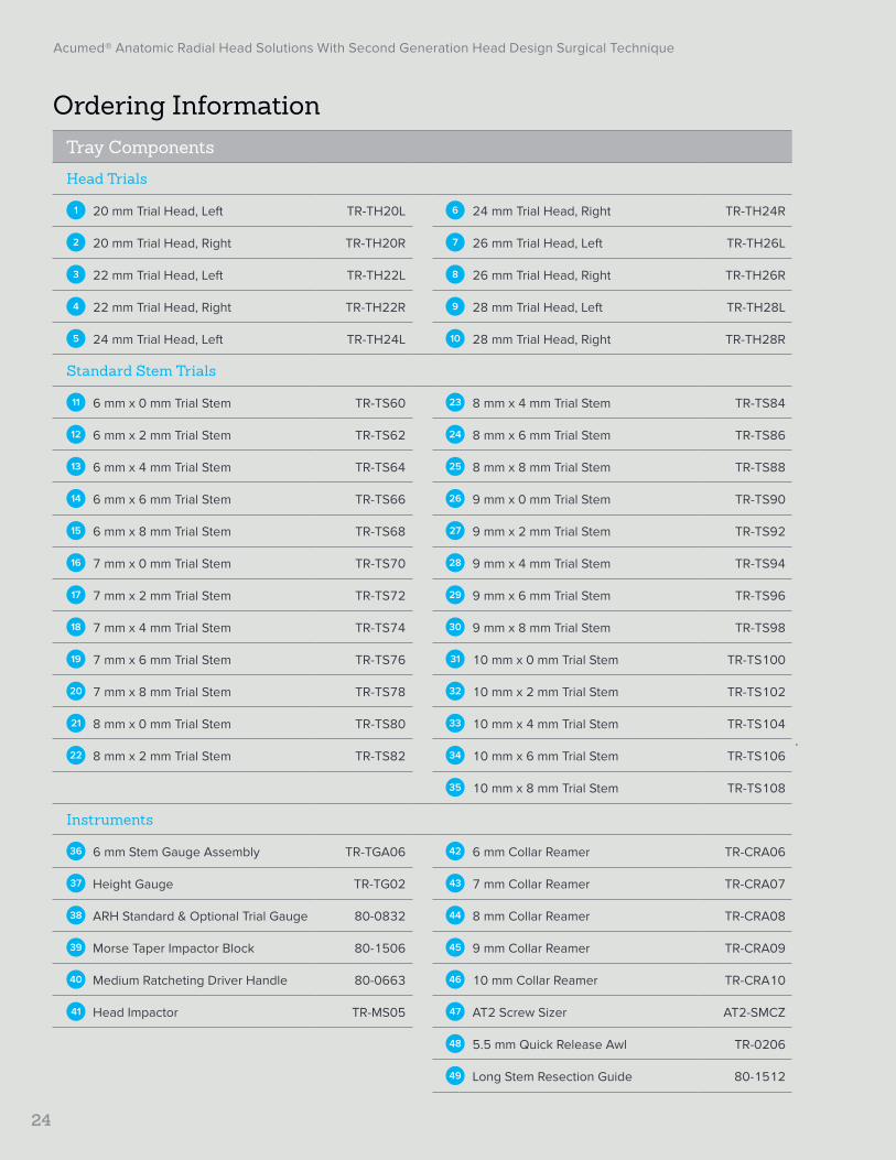
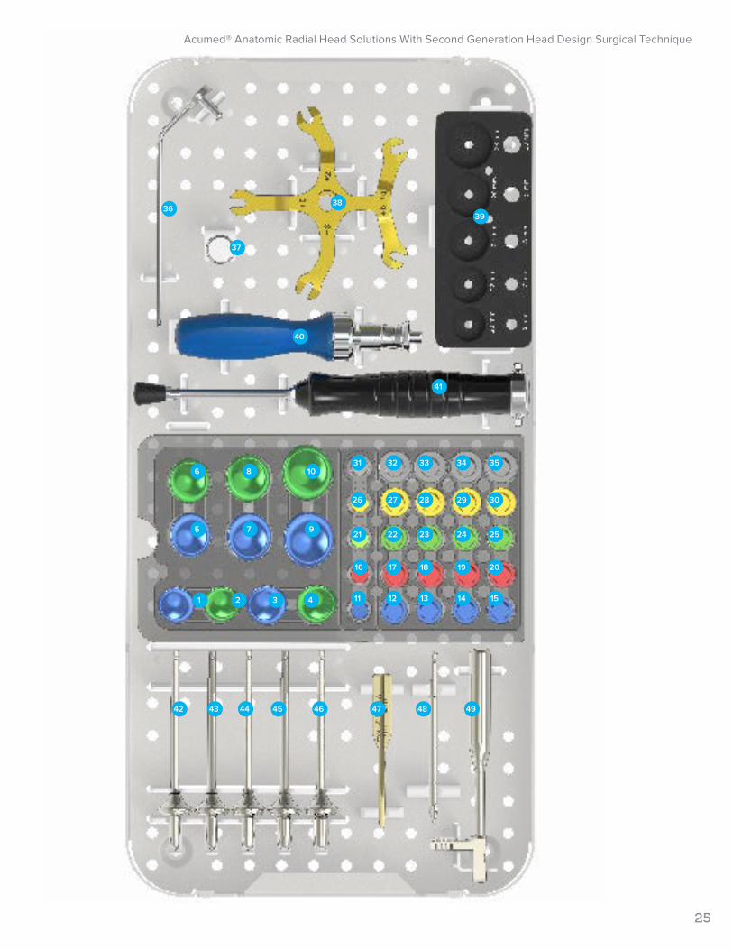
Ordering InformationTray Components
Head Trials
1 20 mm Trial Head, Left TR-TH20L 6 24 mm Trial Head, Right TR-TH24R
2 20 mm Trial Head, Right TR-TH20R 7 26 mm Trial Head, Left TR-TH26L
3 22 mm Trial Head, Left TR-TH22L 8 26 mm Trial Head, Right TR-TH26R
4 22 mm Trial Head, Right TR-TH22R 9 28 mm Trial Head, Left TR-TH28L
5 24 mm Trial Head, Left TR-TH24L 10 28 mm Trial Head, Right TR-TH28R
Standard Stem Trials
11 6 mm x 0 mm Trial Stem TR-TS60 23 8 mm x 4 mm Trial Stem TR-TS84
12 6 mm x 2 mm Trial Stem TR-TS62 24 8 mm x 6 mm Trial Stem TR-TS86
13 6 mm x 4 mm Trial Stem TR-TS64 25 8 mm x 8 mm Trial Stem TR-TS88
14 6 mm x 6 mm Trial Stem TR-TS66 26 9 mm x 0 mm Trial Stem TR-TS90
15 6 mm x 8 mm Trial Stem TR-TS68 27 9 mm x 2 mm Trial Stem TR-TS92
16 7 mm x 0 mm Trial Stem TR-TS70 28 9 mm x 4 mm Trial Stem TR-TS94
17 7 mm x 2 mm Trial Stem TR-TS72 29 9 mm x 6 mm Trial Stem TR-TS96
18 7 mm x 4 mm Trial Stem TR-TS74 30 9 mm x 8 mm Trial Stem TR-TS98
19 7 mm x 6 mm Trial Stem TR-TS76 31 10 mm x 0 mm Trial Stem TR-TS100
20 7 mm x 8 mm Trial Stem TR-TS78 32 10 mm x 2 mm Trial Stem TR-TS102
21 8 mm x 0 mm Trial Stem TR-TS80 33 10 mm x 4 mm Trial Stem TR-TS104
22 8 mm x 2 mm Trial Stem TR-TS82 34 10 mm x 6 mm Trial Stem TR-TS106
35 10 mm x 8 mm Trial Stem TR-TS108
Instruments
36 6 mm Stem Gauge Assembly TR-TGA06 42 6 mm Collar Reamer TR-CRA06
37 Height Gauge TR-TG02 43 7 mm Collar Reamer TR-CRA07
38 ARH Standard & Optional Trial Gauge 80-0832 44 8 mm Collar Reamer TR-CRA08
39 Morse Taper Impactor Block 80-1506 45 9 mm Collar Reamer TR-CRA09
40 Medium Ratcheting Driver Handle 80-0663 46 10 mm Collar Reamer TR-CRA10
41 Head Impactor TR-MS05 47 AT2 Screw Sizer AT2-SMCZ
48 5.5 mm Quick Release Awl TR-0206
49 Long Stem Resection Guide 80-1512
Acumed® Anatomic Radial Head Solutions With Second Generation Head Design Surgical Technique
25
36
41
37
42
38
43
39
40
44 45 46 47 48 49
1 2 3 4
6
5 7 9
8 1031
26
21
11
32
27
22
1716
12
33
28
23
18
13
34
29
24
19
14
35
30
25
20
15
Acumed® Anatomic Radial Head Solutions With Second Generation Head Design Surgical Technique
26
Ordering Information
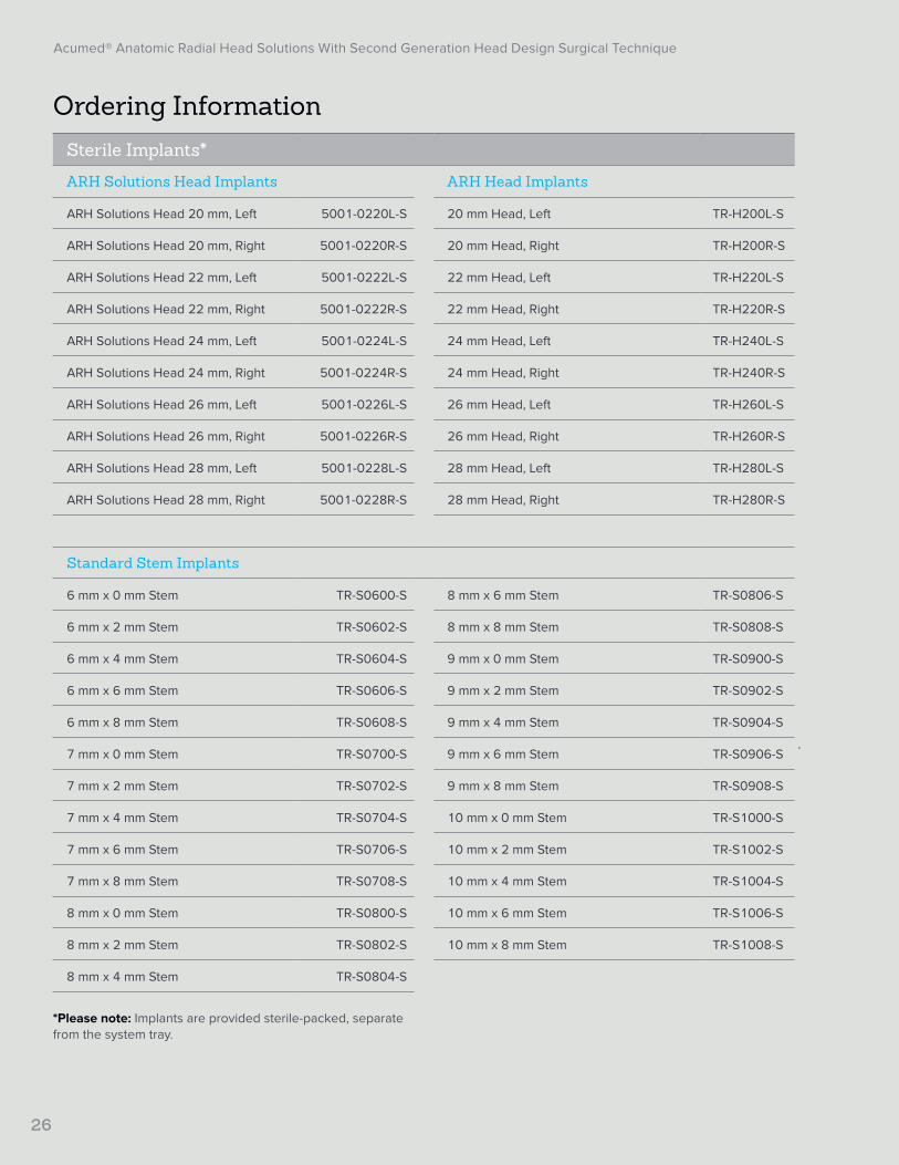
*Please note: Implants are provided sterile-packed, separate from the system tray.
Sterile Implants*
ARH Solutions Head Implants ARH Head Implants
ARH Solutions Head 20 mm, Left 5001-0220L-S 20 mm Head, Left TR-H200L-S
ARH Solutions Head 20 mm, Right 5001-0220R-S 20 mm Head, Right TR-H200R-S
ARH Solutions Head 22 mm, Left 5001-0222L-S 22 mm Head, Left TR-H220L-S
ARH Solutions Head 22 mm, Right 5001-0222R-S 22 mm Head, Right TR-H220R-S
ARH Solutions Head 24 mm, Left 5001-0224L-S 24 mm Head, Left TR-H240L-S
ARH Solutions Head 24 mm, Right 5001-0224R-S 24 mm Head, Right TR-H240R-S
ARH Solutions Head 26 mm, Left 5001-0226L-S 26 mm Head, Left TR-H260L-S
ARH Solutions Head 26 mm, Right 5001-0226R-S 26 mm Head, Right TR-H260R-S
ARH Solutions Head 28 mm, Left 5001-0228L-S 28 mm Head, Left TR-H280L-S
ARH Solutions Head 28 mm, Right 5001-0228R-S 28 mm Head, Right TR-H280R-S
Standard Stem Implants
6 mm x 0 mm Stem TR-S0600-S 8 mm x 6 mm Stem TR-S0806-S
6 mm x 2 mm Stem TR-S0602-S 8 mm x 8 mm Stem TR-S0808-S
6 mm x 4 mm Stem TR-S0604-S 9 mm x 0 mm Stem TR-S0900-S
6 mm x 6 mm Stem TR-S0606-S 9 mm x 2 mm Stem TR-S0902-S
6 mm x 8 mm Stem TR-S0608-S 9 mm x 4 mm Stem TR-S0904-S
7 mm x 0 mm Stem TR-S0700-S 9 mm x 6 mm Stem TR-S0906-S
7 mm x 2 mm Stem TR-S0702-S 9 mm x 8 mm Stem TR-S0908-S
7 mm x 4 mm Stem TR-S0704-S 10 mm x 0 mm Stem TR-S1000-S
7 mm x 6 mm Stem TR-S0706-S 10 mm x 2 mm Stem TR-S1002-S
7 mm x 8 mm Stem TR-S0708-S 10 mm x 4 mm Stem TR-S1004-S
8 mm x 0 mm Stem TR-S0800-S 10 mm x 6 mm Stem TR-S1006-S
8 mm x 2 mm Stem TR-S0802-S 10 mm x 8 mm Stem TR-S1008-S
8 mm x 4 mm Stem TR-S0804-S
Acumed® Anatomic Radial Head Solutions With Second Generation Head Design Surgical Technique
27
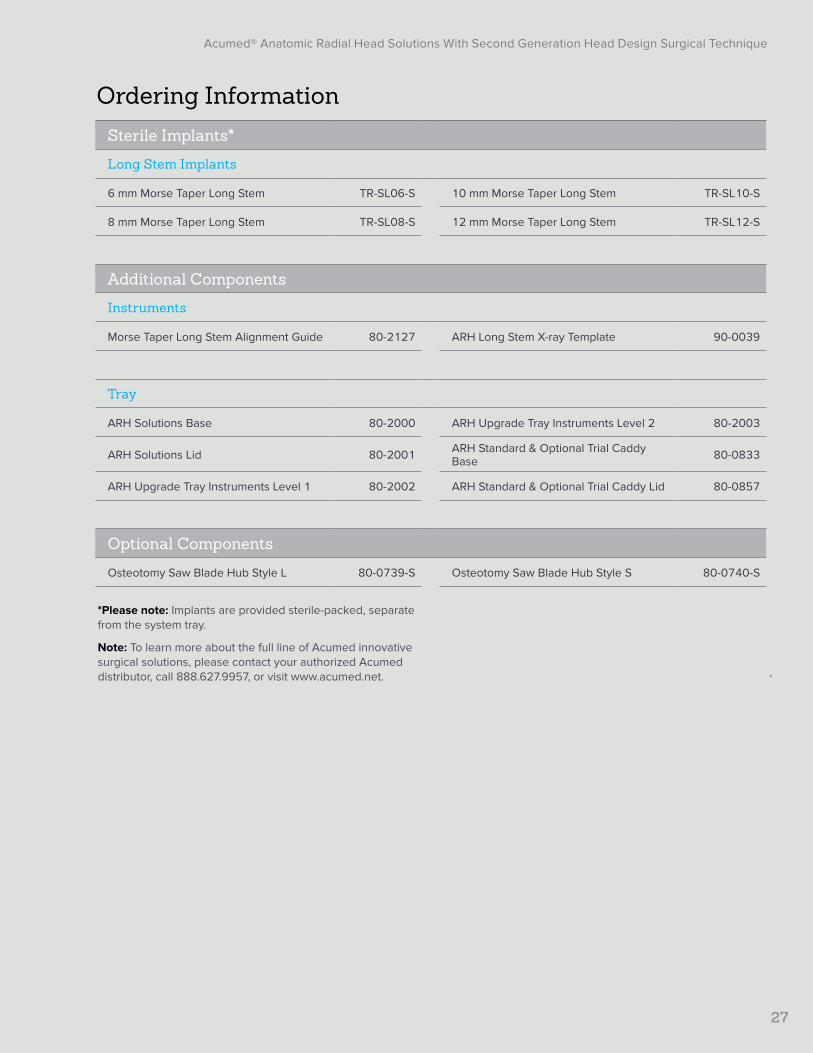
Ordering Information
*Please note: Implants are provided sterile-packed, separate from the system tray.
Note: To learn more about the full line of Acumed innovative surgical solutions, please contact your authorized Acumed distributor, call 888.627.9957, or visit www.acumed.net.
Sterile Implants*
Long Stem Implants
6 mm Morse Taper Long Stem TR-SL06-S 10 mm Morse Taper Long Stem TR-SL10-S
8 mm Morse Taper Long Stem TR-SL08-S 12 mm Morse Taper Long Stem TR-SL12-S
Additional Components
Instruments
Morse Taper Long Stem Alignment Guide 80-2127 ARH Long Stem X-ray Template 90-0039
Tray
ARH Solutions Base 80-2000 ARH Upgrade Tray Instruments Level 2 80-2003
ARH Solutions Lid 80-2001 ARH Standard & Optional Trial Caddy Base 80-0833
ARH Upgrade Tray Instruments Level 1 80-2002 ARH Standard & Optional Trial Caddy Lid 80-0857
Optional Components
Osteotomy Saw Blade Hub Style L 80-0739-S Osteotomy Saw Blade Hub Style S 80-0740-S
Acumed® Anatomic Radial Head Solutions With Second Generation Head Design Surgical Technique
28
References
1. Sahu D, Holmes DM, Fitzsimmons JS, Thoreson AR, Berglund LJ, An KN, O’Driscoll SW. Influence of radial head prosthesis design on radiocapitellar joint contact mechanics. J Shoulder Elbow Surg. 2014;23(4):456-462.
2. Bachman DR, Thaveepunsan S, Park S, Fitzsimmons JS, An KN, O’Driscoll SW. The effect of prosthetic radial head geometry on the distribution and magnitude of radiocapitellar joint contact pressures. J Hand Surg Am. 2015;40(2):281-288.
3. Doornberg JN, Linzel DS, Zurakowski D, Ring D. Reference points for radial head prosthesis size. J Hand Surg Am. 2006;31(1):53-57.

Acumed® Anatomic Radial Head Solutions With Second Generation Head Design Surgical Technique
29
Notes:

Acumed Headquarters5885 NE Cornelius Pass RoadHillsboro, OR 97124 Office: +1.888.627.9957Office: +1.503.627.9957 Fax: +1.503.520.9618 www.acumed.net
These materials contain information about products that may or may not be available in any particular country or may be available under different trademarks in different countries. The products may be approved or cleared by governmental regulatory organizations for sale or use with different indications or restrictions in different countries. Products may not be approved for use in all countries. Nothing contained in these materials should be construed as a promotion or solicitation for any product or for the use of any product in a particular way that is not authorized under the laws and regulations of the country where the reader is located. Nothing in these materials should be construed as a representation or warranty as to the efficacy or quality of any product, nor the appropriateness of any product to treat any specific condition. Physicians may direct questions about the availability and use of the products described in these materials to their authorized Acumed distributor. Specific questions patients may have about the use of the products described in these materials or the appropriateness for their own conditions should be directed to their own physician.
ELB10-07-D | Effective: 2020/10 | © 2020 Acumed® LLC
Acumed® and Acutrak 2® are registered trademarks of Acumed LLC