wixel
DESCRIPTION
Polulu WixelTRANSCRIPT
Pololu Wixel User's GuidePololu Wixel User's Guide © 2001–2012 Pololu Corporation
http://www.pololu.com/docs/0J46/all Page 1 of 61

1. Overview . . . . . . . . . . . . . . . . . . . . . . . . . . . . . . . . . . . . . . . . . . . . . . . . . . . . 31.a. Module Pinout and Components . . . . . . . . . . . . . . . . . . . . . . . . . . . . . . . . . . . . 41.b. Supported Operating Systems . . . . . . . . . . . . . . . . . . . . . . . . . . . . . . . . . . . . . . 71.c. Government Regulations for Radio Devices . . . . . . . . . . . . . . . . . . . . . . . . . . . . . . 7
2. Contacting Pololu . . . . . . . . . . . . . . . . . . . . . . . . . . . . . . . . . . . . . . . . . . . . . . . . 83. Getting Started . . . . . . . . . . . . . . . . . . . . . . . . . . . . . . . . . . . . . . . . . . . . . . . . . 9
3.a. Installing Windows Drivers and Software . . . . . . . . . . . . . . . . . . . . . . . . . . . . . . . 93.b. Installing Linux Drivers and Software . . . . . . . . . . . . . . . . . . . . . . . . . . . . . . . . . 143.c. Installing Mac OS X Drivers and Software . . . . . . . . . . . . . . . . . . . . . . . . . . . . . . . 153.d. Loading an Example App . . . . . . . . . . . . . . . . . . . . . . . . . . . . . . . . . . . . . . . . 16
4. Configuring Your Wixels . . . . . . . . . . . . . . . . . . . . . . . . . . . . . . . . . . . . . . . . . . . . 205. Connecting Your Wixels . . . . . . . . . . . . . . . . . . . . . . . . . . . . . . . . . . . . . . . . . . . . 23
5.a. Connecting Power . . . . . . . . . . . . . . . . . . . . . . . . . . . . . . . . . . . . . . . . . . . . 235.b. Connecting a Microcontroller via TTL Serial . . . . . . . . . . . . . . . . . . . . . . . . . . . . . 245.c. Connecting Buttons and Starting the Bootloader . . . . . . . . . . . . . . . . . . . . . . . . . . . . 25
6. Using a Virtual COM Port . . . . . . . . . . . . . . . . . . . . . . . . . . . . . . . . . . . . . . . . . . . 286.a. Determining the Port Name . . . . . . . . . . . . . . . . . . . . . . . . . . . . . . . . . . . . . . . 286.b. Using a Terminal Program . . . . . . . . . . . . . . . . . . . . . . . . . . . . . . . . . . . . . . . 286.c. Writing PC Software to Use a Serial Port . . . . . . . . . . . . . . . . . . . . . . . . . . . . . . . . 29
7. Ensuring a Good Radio Signal . . . . . . . . . . . . . . . . . . . . . . . . . . . . . . . . . . . . . . . . . 308. Schematic Diagram . . . . . . . . . . . . . . . . . . . . . . . . . . . . . . . . . . . . . . . . . . . . . . . 319. Wixel Apps . . . . . . . . . . . . . . . . . . . . . . . . . . . . . . . . . . . . . . . . . . . . . . . . . . . 32
9.a. Example App: Blink LED . . . . . . . . . . . . . . . . . . . . . . . . . . . . . . . . . . . . . . . . 329.b. Wireless Serial App . . . . . . . . . . . . . . . . . . . . . . . . . . . . . . . . . . . . . . . . . . . 329.c. USB-to-Serial App . . . . . . . . . . . . . . . . . . . . . . . . . . . . . . . . . . . . . . . . . . . 379.d. I/O Repeater App . . . . . . . . . . . . . . . . . . . . . . . . . . . . . . . . . . . . . . . . . . . . 389.e. ShiftBrite App . . . . . . . . . . . . . . . . . . . . . . . . . . . . . . . . . . . . . . . . . . . . . . 419.f. Wireless Tilt Mouse App . . . . . . . . . . . . . . . . . . . . . . . . . . . . . . . . . . . . . . . . 439.g. Serial-to-I²C App . . . . . . . . . . . . . . . . . . . . . . . . . . . . . . . . . . . . . . . . . . . . 45
10. Writing Your Own Wixel App . . . . . . . . . . . . . . . . . . . . . . . . . . . . . . . . . . . . . . . . 5010.a. Getting Started in Windows . . . . . . . . . . . . . . . . . . . . . . . . . . . . . . . . . . . . . . 5010.b. Compiling an Example App . . . . . . . . . . . . . . . . . . . . . . . . . . . . . . . . . . . . . . 5010.c. Using the Eclipse IDE . . . . . . . . . . . . . . . . . . . . . . . . . . . . . . . . . . . . . . . . . 5210.d. Sharing Your App with the Wixel Community . . . . . . . . . . . . . . . . . . . . . . . . . . . . 5610.e. USB Configurations Recognized by the Wixel Configuration Software . . . . . . . . . . . . . . . 5810.f. Wixel App File Format . . . . . . . . . . . . . . . . . . . . . . . . . . . . . . . . . . . . . . . . . 58
11. The Wixel USB Bootloader . . . . . . . . . . . . . . . . . . . . . . . . . . . . . . . . . . . . . . . . . . 60
Pololu Wixel User's Guide © 2001–2012 Pololu Corporation
Page 2 of 61
Wixel programmable USBwireless module.
Wixel programmable USBwireless module enablingwireless communicationbetween a PC and robot.
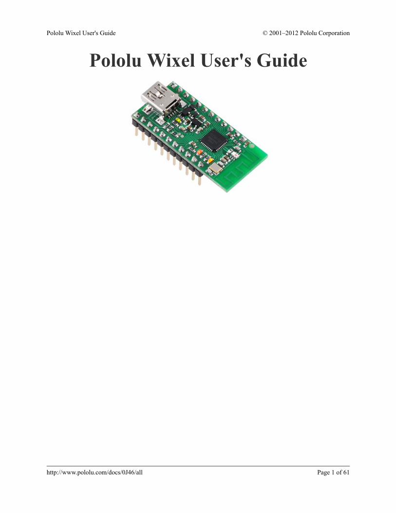
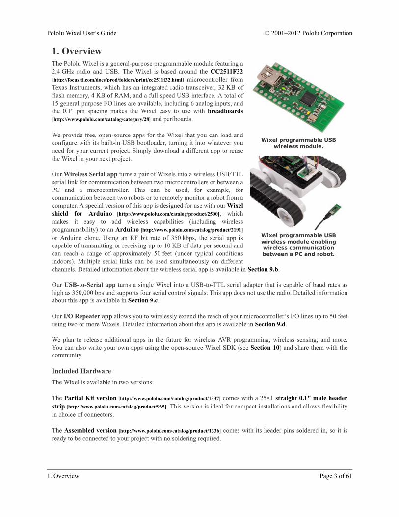
1. OverviewThe Pololu Wixel is a general-purpose programmable module featuring a2.4 GHz radio and USB. The Wixel is based around the CC2511F32[http://focus.ti.com/docs/prod/folders/print/cc2511f32.html] microcontroller fromTexas Instruments, which has an integrated radio transceiver, 32 KB offlash memory, 4 KB of RAM, and a full-speed USB interface. A total of15 general-purpose I/O lines are available, including 6 analog inputs, andthe 0.1" pin spacing makes the Wixel easy to use with breadboards[http://www.pololu.com/catalog/category/28] and perfboards.
We provide free, open-source apps for the Wixel that you can load andconfigure with its built-in USB bootloader, turning it into whatever youneed for your current project. Simply download a different app to reusethe Wixel in your next project.
Our Wireless Serial app turns a pair of Wixels into a wireless USB/TTLserial link for communication between two microcontrollers or between aPC and a microcontroller. This can be used, for example, forcommunication between two robots or to remotely monitor a robot from acomputer. A special version of this app is designed for use with our Wixelshield for Arduino [http://www.pololu.com/catalog/product/2500], whichmakes it easy to add wireless capabilities (including wirelessprogrammability) to an Arduino [http://www.pololu.com/catalog/product/2191]or Arduino clone. Using an RF bit rate of 350 kbps, the serial app iscapable of transmitting or receiving up to 10 KB of data per second andcan reach a range of approximately 50 feet (under typical conditionsindoors). Multiple serial links can be used simultaneously on differentchannels. Detailed information about the wireless serial app is available in Section 9.b.
Our USB-to-Serial app turns a single Wixel into a USB-to-TTL serial adapter that is capable of baud rates ashigh as 350,000 bps and supports four serial control signals. This app does not use the radio. Detailed informationabout this app is available in Section 9.c.
Our I/O Repeater app allows you to wirelessly extend the reach of your microcontroller’s I/O lines up to 50 feetusing two or more Wixels. Detailed information about this app is available in Section 9.d.
We plan to release additional apps in the future for wireless AVR programming, wireless sensing, and more.You can also write your own apps using the open-source Wixel SDK (see Section 10) and share them with thecommunity.
Included HardwareThe Wixel is available in two versions:
The Partial Kit version [http://www.pololu.com/catalog/product/1337] comes with a 25×1 straight 0.1" male headerstrip [http://www.pololu.com/catalog/product/965]. This version is ideal for compact installations and allows flexibilityin choice of connectors.
The Assembled version [http://www.pololu.com/catalog/product/1336] comes with its header pins soldered in, so it isready to be connected to your project with no soldering required.
Pololu Wixel User's Guide © 2001–2012 Pololu Corporation
1. Overview Page 3 of 61

Wixel programmable USB wirelessmodule (without header pins installed).
Wixel programmable USB wirelessmodule (fully assembled).
1.a. Module Pinout and Components
The Wixel can connect to a computer’s USB port via a USB A to Mini-B cable [http://www.pololu.com/catalog/product/130] or a USB A to Mini-B adapter [http://www.pololu.com/catalog/product/1126] (not included). The USBconnection is used to configure the Wixel and also to transmit and receive data. The USB connection can alsoprovide power to the Wixel.
On the side of the board opposite the USB connector, the Wixel has a 2.4 GHz PCB trace antenna. This antenna,along with the other RF circuitry, forms a radio that allows the Wixel to send and receive data packets in the2.4 GHz band. The Wixel is based on the CC2511F32 microcontroller from Texas Instruments, which makes itcompatible with the CC2500 transceiver, the CC2510Fx family, and the CC2511Fx family of chips from TexasInstruments. The Wixel’s radio is not compatible with Wi-Fi, Zigbee, or Bluetooth. The antenna is a “meanderedInverted F” design that is described in Texas Instrument’s application note AN043 [http://focus.ti.com/lit/an/swra117d/swra117d.pdf].
Pololu Wixel User's Guide © 2001–2012 Pololu Corporation
1. Overview Page 4 of 61

Wixel programmable USB wirelessmodule, bottom view with US
quarter for size reference.
The three GND pins are all connected and are at 0 V by definition.When connecting the Wixel to other electronic systems, you shouldmake sure that the Wixel’s GND is connected to the other system’sGND unless you are doing something very advanced.
The Wixel can be powered from VIN pin. Simply connect a 2.7–6.5 Vpower source between VIN and GND, with the positive terminal goingto VIN. It is OK to connect VIN and USB at the same time. See Section5.a for more information about powering your Wixels.
The VALT pin is connected to three things: the 5V USB bus power fromthe USB port (through a diode), VIN (through a diode), and to the inputof the Wixel’s on-board 3.3 V regulator. The connection to 5V isswitched off when a power supply is connected to VIN. Most peoplewill not need to use the VALT pin: see Section 5.a for example uses.
The pin labeled 3V3 on the board (3.3V Output in the diagram above)is connected to the output of the Wixel’s 3.3V regulator. This powersource can be used to power other low-current peripherals in yoursystem. With an input voltage of 5 V (either from USB, VIN, or VALT), this output can provide up to 150 mA ofcurrent. At higher input voltages, this output can provide up to 100 mA.
The pin labeled RST on the board (RESET in the diagram above) is the reset line of the microcontroller. This pincan be driven low to perform a hard reset of the Wixel’s microcontroller. This should not be necessary for typicalusers, but it can be useful while you are developing a Wixel application (see Section 5.c). This pin is internallypulled high to 3.3 V, so it is okay to leave it unconnected. If you do wire something to this pin, the CC2511F32datasheet recommends adding an external RC filter with values of 1 nF and 2.7 kΩ close to the pin in order toavoid unintended reset of the microcontroller.
The Wixel has 15 free I/O lines whose behavior depends on the application that is loaded onto the Wixel.Specifically, these are all of the pins on Port 0 (P0_0 through P0_5), all of the pins on Port 1 (P1_0 throughP1_7), and P2_1. The P2_1 pin is tied to the red LED but the other 14 free I/O lines are only connected to themicrocontroller. The P2_2 line is also accessible, but it is tied to the yellow LED and is used to get the Wixel intobootloader mode (see Section 5.c).
The amount of current that can be supplied by the CC2511F32’s I/O pins is not well-documented by themanufacturer. According to this forum post by a TI Employee [http://e2e.ti.com/support/low_power_rf/f/155/p/31555/319919.aspx], regular I/O pins are designed to be able to source 4 mA while P1_0 and P1_1 are designed for 20 mA.
Caution: The Wixel’s I/O lines are not 5V tolerant. You must use level-shifters, diodes, or voltagedividers to connect the Wixel to outputs from 5V systems.
The CC2511F32 has several peripherals that are available to be used in Wixel applications:
• 2 USARTs which can perform asynchronous serial or SPI communication
• 3 timers that are capable of PWM output as shown above, plus 1 more internal timer
• 6 analog input-capable pins, connected to a 7–12 bit ADC
Pololu Wixel User's Guide © 2001–2012 Pololu Corporation
1. Overview Page 5 of 61
Wixel indicator LEDs.
Different Wixel applications may use different sets of these peripherals. Consult the application documentationfor details on the behavior of the I/O lines.
The pinout and peripheral diagram at the top of this section is also available as a printable pdf[http://www.pololu.com/file/download/wixel_pinout.pdf?file_id=0J462] (145k pdf).
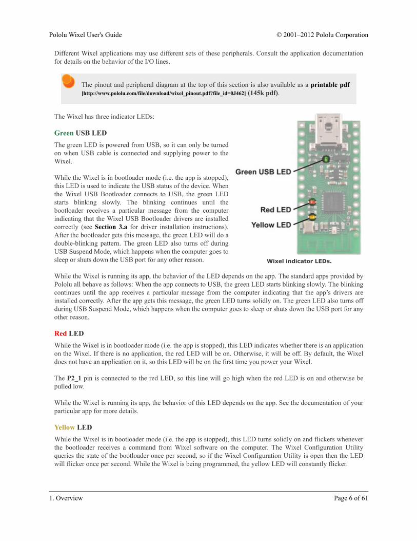
The Wixel has three indicator LEDs:
Green USB LEDThe green LED is powered from USB, so it can only be turnedon when USB cable is connected and supplying power to theWixel.
While the Wixel is in bootloader mode (i.e. the app is stopped),this LED is used to indicate the USB status of the device. Whenthe Wixel USB Bootloader connects to USB, the green LEDstarts blinking slowly. The blinking continues until thebootloader receives a particular message from the computerindicating that the Wixel USB Bootloader drivers are installedcorrectly (see Section 3.a for driver installation instructions).After the bootloader gets this message, the green LED will do adouble-blinking pattern. The green LED also turns off duringUSB Suspend Mode, which happens when the computer goes tosleep or shuts down the USB port for any other reason.
While the Wixel is running its app, the behavior of the LED depends on the app. The standard apps provided byPololu all behave as follows: When the app connects to USB, the green LED starts blinking slowly. The blinkingcontinues until the app receives a particular message from the computer indicating that the app’s drivers areinstalled correctly. After the app gets this message, the green LED turns solidly on. The green LED also turns offduring USB Suspend Mode, which happens when the computer goes to sleep or shuts down the USB port for anyother reason.
Red LEDWhile the Wixel is in bootloader mode (i.e. the app is stopped), this LED indicates whether there is an applicationon the Wixel. If there is no application, the red LED will be on. Otherwise, it will be off. By default, the Wixeldoes not have an application on it, so this LED will be on the first time you power your Wixel.
The P2_1 pin is connected to the red LED, so this line will go high when the red LED is on and otherwise bepulled low.
While the Wixel is running its app, the behavior of this LED depends on the app. See the documentation of yourparticular app for more details.
Yellow LEDWhile the Wixel is in bootloader mode (i.e. the app is stopped), this LED turns solidly on and flickers wheneverthe bootloader receives a command from Wixel software on the computer. The Wixel Configuration Utilityqueries the state of the bootloader once per second, so if the Wixel Configuration Utility is open then the LEDwill flicker once per second. While the Wixel is being programmed, the yellow LED will constantly flicker.
Pololu Wixel User's Guide © 2001–2012 Pololu Corporation
1. Overview Page 6 of 61

The P2_2 pin is connected to the yellow LED, so this line will go high when the yellow LED is on and otherwisebe pulled low.
While the Wixel is running its app, the behavior of this LED depends on the app. See the documentation of yourparticular app for more details.
1.b. Supported Operating SystemsThe Wixel USB drivers and configuration software currently work under Windows 8, Windows 7, WindowsVista, Microsoft Windows XP (SP 3), Linux, and Mac OS X.
Any Wixel app that implements a single USB virtual COM port will work on Linux or Mac OS X with nospecial driver installation required. Any Wixel app that implements a Human Interface Device (HID) will workon Windows, Linux, or Mac OS X with no special driver installation required.
Mac OS X compatibility: we have confirmed that the Wixel works on Mac OS X 10.7 and wecan assist with advanced technical issues, but most of our tech support staff does not use Macs, sobasic support for Mac OS X is limited.
1.c. Government Regulations for Radio Devices
Warning about radio regulations: The Wixel has not been tested or certified for conformance withany radio regulations, and the Wixel is shipped with only a bootloader that does not use the radio.The 2.4 GHz band is relatively unrestricted in many parts of the world, but it is your responsibility tocomply with your local regulations if you program your Wixel to use its wireless capabilities.
The Wixel is a multi-purpose development platform, not a finished product, and it is not certified by the FCCor any other government agency. It is your responsibility to follow local regulations and use good engineeringpractices when developing, installing, and configuring apps for your Wixel. The Wixel has a low-power radio anduses the reference PCB antenna suggested by TI, so we expect typical applications developed for the Wixel tocomply with FCC rules, but the Wixel is not intended for integration into other products. If you are contemplatingadding Wixel-like features to your product, we recommend that you integrate the CC2511 IC directly usingdocumentation from TI; any software developed for the Wixel should work on any other CC2511-based platform.For more information on the requirements for operating a 2.4 GHz device, see TI Application Note 032:SRD regulations for license-free transceiver operation in the 2.4 GHz band [http://focus.ti.com/lit/an/swra060/swra060.pdf].
Pololu Wixel User's Guide © 2001–2012 Pololu Corporation
1. Overview Page 7 of 61

Wixel programmable USBwireless module with USB cabled
connected.
2. Contacting PololuWe would be delighted to hear from you about any of your projects andabout your experience with the Wixel. You can contact us[http://www.pololu.com/contact] directly or post on our forum[http://forum.pololu.com/]. Tell us what we did well, what we could improve,what you would like to see in the future, or anything else you would liketo say!
Pololu Wixel User's Guide © 2001–2012 Pololu Corporation
2. Contacting Pololu Page 8 of 61
3. Getting Started3.a. Installing Windows Drivers and SoftwareBefore you connect a Wixel to a computer running Microsoft Windows, you should install the drivers:
1. Download the Wixel Windows Drivers and Software [http://www.pololu.com/file/download/wixel-windows-121129.zip?file_id=0J448] (12MB zip)
2. Open the ZIP archive and run setup.exe. The installer will guide you through the steps required to installthe Wixel Configuration Utility, the Wixel command-line utility (WixelCmd), and the Wixel drivers on yourcomputer. If the installer fails when run directly from the ZIP file, extract the contents of the ZIP file to atemporary directory on your computer, right click setup.exe, and select “Run as Administrator”.
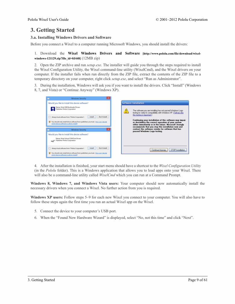
3. During the installation, Windows will ask you if you want to install the drivers. Click “Install” (Windows8, 7, and Vista) or “Continue Anyway” (Windows XP).
4. After the installation is finished, your start menu should have a shortcut to the Wixel Configuration Utility(in the Pololu folder). This is a Windows application that allows you to load apps onto your Wixel. Therewill also be a command-line utility called WixelCmd which you can run at a Command Prompt.
Windows 8, Windows 7, and Windows Vista users: Your computer should now automatically install thenecessary drivers when you connect a Wixel. No further action from you is required.
Windows XP users: Follow steps 5–9 for each new Wixel you connect to your computer. You will also have tofollow these steps again the first time you run an actual Wixel app on the Wixel.
5. Connect the device to your computer’s USB port.
6. When the “Found New Hardware Wizard” is displayed, select “No, not this time” and click “Next”.
Pololu Wixel User's Guide © 2001–2012 Pololu Corporation
3. Getting Started Page 9 of 61

7. On the second screen of the “Found New Hardware Wizard”, select “Install the software automatically”and click “Next”.
Pololu Wixel User's Guide © 2001–2012 Pololu Corporation
3. Getting Started Page 10 of 61
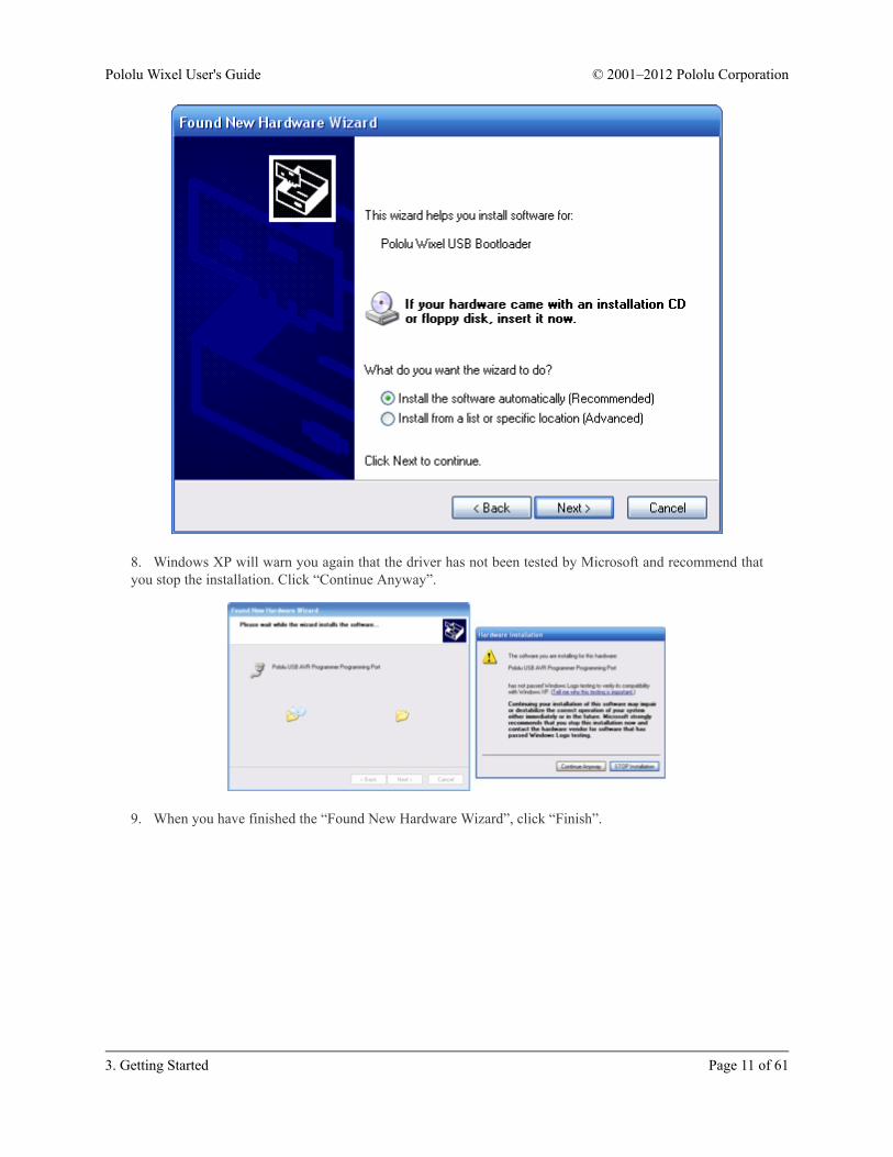
8. Windows XP will warn you again that the driver has not been tested by Microsoft and recommend thatyou stop the installation. Click “Continue Anyway”.
9. When you have finished the “Found New Hardware Wizard”, click “Finish”.
Pololu Wixel User's Guide © 2001–2012 Pololu Corporation
3. Getting Started Page 11 of 61

After installing the drivers, if you go to your computer’s Device Manager and expand the “Pololu USB Devices”list, you should see an entry for the Pololu Wixel USB Bootloader.
Windows Vista or Windows 7 DeviceManager showing a Wixel in bootloader
mode.
Windows XP Device Manager showing aWixel in bootloader mode.
If you see the “Pololu Wixel USB Bootloader” entry in your device manager, it means that your Wixel is inbootloader mode. Your Wixel should go into bootloader mode when you first plug it into USB, because there is noapp on the Wixel by default. Once you have loaded an app onto the Wixel using the Wixel Configuration Utility,and the app is running, then you will not see the Pololu Wixel USB Bootloader entry in your Device Manager.The entry you see in the Device Manager will depend on the application that is loaded on the Wixel. Some appsmight not enable the USB interface, in which case you will see no entry for the Wixel in the Device Manager.However, typical Wixel Apps will appear in your Device Manager as a single Virtual COM port (with product ID0x2200) in the “Ports (COM & LPT)” list as shown below:
Pololu Wixel User's Guide © 2001–2012 Pololu Corporation
3. Getting Started Page 12 of 61

Windows Vista or Windows 7 DeviceManager showing a Wixel that is
running an app with a virtual COM port.
Windows XP Device Manager showing aWixel that is running an app with a
virtual COM port.
In parentheses, you will see the name of the port (for example, COM5 or COM6). Some software will not allowconnection to higher COM port numbers. If you need to change the COM port number assigned to a Wixel, youcan do so using the Device Manager. Bring up the properties dialog for the COM port and click the “Advanced…”button in the “Port Settings” tab. From this dialog you can change the COM port assigned to your device.Windows will remember which COM port was assigned to which Wixel using the built-in serial number of theWixel; a given Wixel will always get assigned to the same COM port regardless of which USB port it is pluggedinto.
Pololu Wixel User's Guide © 2001–2012 Pololu Corporation
3. Getting Started Page 13 of 61

3.b. Installing Linux Drivers and Software
The Wixel Configuration Utility running in Ubuntu Linux.
You can download the Wixel Configuration Utility and the Wixel command-line utility (wixelcmd) for Linuxhere:
• Wixel Linux Software for i386 (32-bit) [http://www.pololu.com/file/download/wixel-linux-110623-i386.tar.gz?file_id=0J489] (211k gz)
• Wixel Linux Software for amd64 (64-bit) [http://www.pololu.com/file/download/wixel-linux-110623-amd64.tar.gz?file_id=0J490] (216k gz)
Unzip the tar/gzip archive by running “tar -xzvf” followed by the name of the file. After following the instructionsin README.txt, you can run the programs by executing wixelconfig or wixelcmd.
Any Wixel app that implements a USB virtual COM port or a Human Interface Device (HID) will work on Linuxwith no special driver installation required.
The virtual COM ports are managed by the cdc-acm kernel module, whose source code you can find inyour kernel’s source code in drivers/usb/class/cdc-acm.c. When you connect a Wixel running an app that
Pololu Wixel User's Guide © 2001–2012 Pololu Corporation
3. Getting Started Page 14 of 61

implements a virtual serial port to the PC, the virtual serial port should appear as a device with a name like /dev/
ttyACM0 (the number depends on how many other ACM devices you have plugged in). You can use any terminalprogram (such as kermit or screen) to send and receive bytes on those ports.
3.c. Installing Mac OS X Drivers and Software
Mac OS X compatibility: we have confirmed that the Wixel works on Mac OS X 10.7 and wecan assist with advanced technical issues, but most of our tech support staff does not use Macs, sobasic support for Mac OS X is limited.
The Wixel Configuration Utility running in Mac OS X.
You can download the Wixel Configuration Utility and the Wixel command-line utility (wixelcmd) for Mac OSX here:
• Wixel Mac Software [http://www.pololu.com/file/download/wixel-mac-120514.dmg?file_id=0J550] (8MB dmg)
Double click on the dmg file to open it, and then follow the instructions in README.txt.
The virtual COM ports are managed by the AppleUSBCDCACM component of Mac OS X. The source code[http://www.opensource.apple.com] of AppleUSBCDCACM is available from Apple. When you connect a Wixelrunning an app that implements a virtual serial port to the PC, the virtual serial port should appear as a devicewith a name like /dev/cu.usbmodemfa121 (the number depends on which USB port you use). You can use anyterminal program (such as screen) to send and receive bytes on those ports.
Pololu Wixel User's Guide © 2001–2012 Pololu Corporation
3. Getting Started Page 15 of 61

3.d. Loading an Example AppWhen you first get your Wixel it will have no application loaded. To make your Wixel do something useful, youmust load an app onto it. This section guides you through the steps needed to load an example application ontothe Wixel using the Wixel Configuration Utility.
1. Install the Wixel drivers and software by following the instructions in the preceding sections.
2. Download the example application here: Example Blink LED App v1.0 [http://www.pololu.com/file/download/example_blink_led_v1.0.wxl?file_id=0J449] (11k wxl). If you want to see the source code, it is in the WixelSDK under apps/example_blink_led. (See Section 10.a.)
3. Open the app in the Wixel Configuration Utility. To do this in Windows, you can simply double-click onthe Wixel App (WXL) file. Alternatively, you can open the Wixel Configuration Utility, click the “Open…”button, and select the Wixel App file. In Windows, you can find the Wixel Configuration Utility in the Pololufolder in your Start Menu.
4. Connect a Wixel to your computer via USB. You should see it appear in the “Wixels” list. If it does notappear, you might need to use a button or wire to get your Wixel into bootloader mode (see Section 5.c). Atthis point, your screen should look something like this:
Pololu Wixel User's Guide © 2001–2012 Pololu Corporation
3. Getting Started Page 16 of 61

The Wixel Configuration Utility with the Example Blink LED App open.
5. Note that in the Wixels box, there is a list of all the Wixels connected to USB that the WixelConfiguration Utility can recognize. There is one Wixel connected, and its 32-bit serial number is displayedin the list. Also note that in the App Configuration box, we have opened the example_blink_led_v1.0.wxlapp. This app has one parameter, blink_period_ms, and it is currently set to 500 (the default).
6. Select the Wixel by left-clicking on its entry in the Wixels list. If you see a dialog box pop up, thisis because the Wixel already has an application on it and the Auto Read checkbox is checked. Click the“Cancel” button in that dialog because we are not interested in reading the contents of the Wixel yet.
7. Click the Write to Wixel button. This writes the currently open app and the settings to the selectedWixel, and then starts running the application.
8. The example blink LED application should be running now. The Wixel’s yellow LED should be off,and the red LED should be blinking. If you are in Windows XP and this is the first time you have run anapplication on this Wixel, the Found New Hardware Wizard will pop up and you will have to follow steps5–9 from Section 3.a to install the drivers properly. After the USB drivers are installed properly, the greenLED should be on solid. Congratulations, you have successfully configured your Wixel!
Pololu Wixel User's Guide © 2001–2012 Pololu Corporation
3. Getting Started Page 17 of 61
9. The speed of the blinking is determined by the blink_period_ms parameter. The units of this parameterare milliseconds (ms). Try changing blink_period_ms to 100 by double-clicking on the number and typing“100”. You can now write the new configuration to the Wixel by clicking the “Write to Wixel” button. Afterthe writing is done and the app is running, you should see the red LED blinking 5 times faster than it wasbefore.
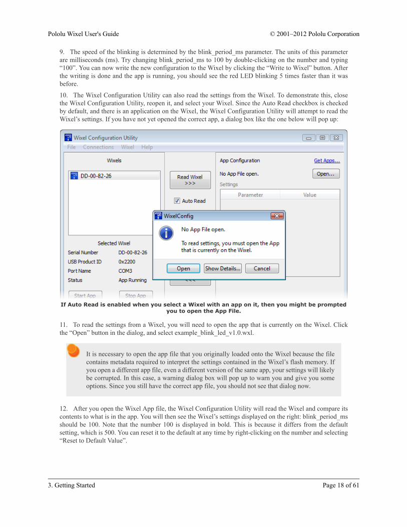
10. The Wixel Configuration Utility can also read the settings from the Wixel. To demonstrate this, closethe Wixel Configuration Utility, reopen it, and select your Wixel. Since the Auto Read checkbox is checkedby default, and there is an application on the Wixel, the Wixel Configuration Utility will attempt to read theWixel’s settings. If you have not yet opened the correct app, a dialog box like the one below will pop up:
If Auto Read is enabled when you select a Wixel with an app on it, then you might be promptedyou to open the App File.
11. To read the settings from a Wixel, you will need to open the app that is currently on the Wixel. Clickthe “Open” button in the dialog, and select example_blink_led_v1.0.wxl.
It is necessary to open the app file that you originally loaded onto the Wixel because the filecontains metadata required to interpret the settings contained in the Wixel’s flash memory. Ifyou open a different app file, even a different version of the same app, your settings will likelybe corrupted. In this case, a warning dialog box will pop up to warn you and give you someoptions. Since you still have the correct app file, you should not see that dialog now.
12. After you open the Wixel App file, the Wixel Configuration Utility will read the Wixel and compare itscontents to what is in the app. You will then see the Wixel’s settings displayed on the right: blink_period_msshould be 100. Note that the number 100 is displayed in bold. This is because it differs from the defaultsetting, which is 500. You can reset it to the default at any time by right-clicking on the number and selecting“Reset to Default Value”.
Pololu Wixel User's Guide © 2001–2012 Pololu Corporation
3. Getting Started Page 18 of 61

After completing this tutorial you should be comfortable with writing apps to the Wixel and reading back thesettings. This is all you need to know in order to configure your Wixels. When you load a real application, suchas the Wireless Serial App [http://www.pololu.com/docs/0J46/9.b], the only thing that will be different are the namesand meanings of the parameters. To understand what the different parameters mean, refer to the documentationfor your specific app.
Some apps might implement a non-standard USB interface (or no USB interface at all). In that case, they willnot be recognized by the Wixel Configuration Utility while the app is running, so you will need to get them intobootloader mode manually (see Section 5.c and also the app’s documentation).
Pololu Wixel User's Guide © 2001–2012 Pololu Corporation
3. Getting Started Page 19 of 61
4. Configuring Your WixelsThe Wixel Configuration Utility allows you to write and read settings from the Wixel. This section explains all ofthe features of the Wixel Configuration Utility in detail.
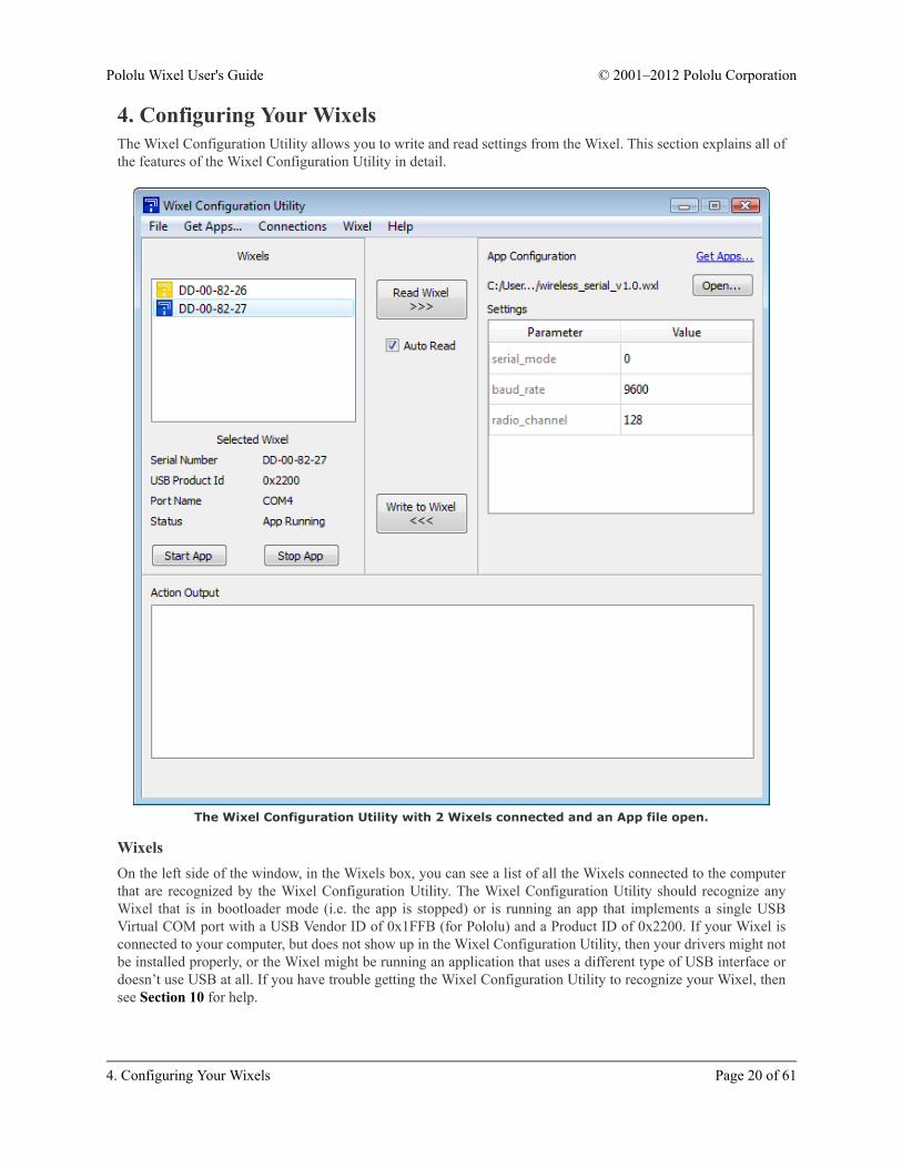
The Wixel Configuration Utility with 2 Wixels connected and an App file open.
WixelsOn the left side of the window, in the Wixels box, you can see a list of all the Wixels connected to the computerthat are recognized by the Wixel Configuration Utility. The Wixel Configuration Utility should recognize anyWixel that is in bootloader mode (i.e. the app is stopped) or is running an app that implements a single USBVirtual COM port with a USB Vendor ID of 0x1FFB (for Pololu) and a Product ID of 0x2200. If your Wixel isconnected to your computer, but does not show up in the Wixel Configuration Utility, then your drivers might notbe installed properly, or the Wixel might be running an application that uses a different type of USB interface ordoesn’t use USB at all. If you have trouble getting the Wixel Configuration Utility to recognize your Wixel, thensee Section 10 for help.
Pololu Wixel User's Guide © 2001–2012 Pololu Corporation
4. Configuring Your Wixels Page 20 of 61

The text displayed in the Wixel list (e.g. “07-C2-C8-3A”) is the serial number of your Wixel. Each Wixel has aunique 32-bit serial number which was randomly generated and assigned to it when the Wixel was manufactured.
The icon displayed in the Wixel list represents the current state of the Wixel. Each Wixel will be in one of thesestates:
Wixel Status Icon Description
App Running The app you loaded on the Wixel is now running.
App Stopped The app you loaded on the Wixel is currently stopped; the Wixel is in bootloader mode.
No App There is no app on the Wixel; the Wixel is in bootloader mode.
Reconnecting The Wixel is reconnecting, disconnecting, or in a transitional state.
If you select a Wixel, you can see more information about it in the area below the list. The USB Product ID is thecurrent product ID presented by the Wixel on its USB interface, as defined in the USB Specification. The PortName is the name of the virtual COM port that has been assigned to the Wixel. In Windows, the Port Name isalso available in the Device Manager.
The Stop App button stops the application that is running on the currently-selected Wixel, putting that Wixel intobootloader mode. The Start App button takes the Wixel out of bootloader mode to run the application that iscurrently on it.
App ConfigurationOn the right side of the window, in the App Configuration box, you can see the name of the currently-open appand the current settings.
You can open a different app by clicking the “Open…” button. In Windows, you can also open an app simply bydouble-clicking on it. The Wixel Configuration Utility can open app files in either the WXL format (documentedin Section 9.d) or the standard Intel HEX [http://en.wikipedia.org/wiki/Intel_HEX] format.
You can change the current settings by double-clicking on a value and typing a new value in. The parameters thatare available depend on the app that is open; different apps have different parameters available.
Please see the documentation for your specific application for an explanation of what the parametersmean, and what the valid values are. The Wixel Configuration Utility will not prevent you fromentering invalid or inconsistent values.
Writing to a WixelAfter you have chosen the app and settings you want to use, and selected a Wixel, you can write the app andsettings to the Wixel by clicking the Write to Wixel button. This will erase whatever application was previouslyon the Wixel and write the new application to the Wixel. When the write operation is done, the Wixel will berestarted and the application should start running.
Reading from a WixelTo read the settings from a Wixel that has been programmed, select the Wixel. If the Auto Read checkbox ischecked, then the Wixel will automatically be read. Uncheck this box if you want to retain current settings when
Pololu Wixel User's Guide © 2001–2012 Pololu Corporation
4. Configuring Your Wixels Page 21 of 61

changing Wixels (for example, when you want to write the same app and settings to multiple Wixels). If the boxis unchecked, you can click the Read Wixel button at any time to read settings from the selected Wixel.
To read the settings from a Wixel, you will need to open the app that is currently on the Wixel. This is necessarybecause the app file contains metadata which is needed in order to correctly interpret the settings contained in theWixel’s flash memory.
If you have lost the app file and want to read the contents of your Wixel, select Read Flash and Export to HEXFile… from the Wixel menu. You can then open the exported HEX File as an App and use it to program otherWixels. The settings from the Wixel will be contained in the exported HEX file but you will not be able to readthese settings in the Wixel Configuration Utility.
If the Wixel’s application is running when the read operation starts, the Wixel Configuration Utility willtemporarily stop the application and put the Wixel into bootloader mode in order to read its contents. When theread operation is completed, the Wixel Configuration Utility will restart the app.
Other CommandsThe Erase Wixel command (found in the Wixel menu) erases the app from the currently selected Wixel (everybit in the application flash section becomes a 1).
The Verify Wixel command reads the currently selected Wixel and tells you whether its contents are identical tothe app and settings displayed on the right in the App Configuration box.
Pololu Wixel User's Guide © 2001–2012 Pololu Corporation
4. Configuring Your Wixels Page 22 of 61

5. Connecting Your WixelsThis chapter explains some of the electrical connections you might need to make to get your Wixel working theway you want it to.
5.a. Connecting PowerThe two main ways of powering the Wixel are the USB port and the VIN pin. The schematic of the Wixel’s powersystem is shown below:
Wixel power system schematic diagram.
VIN Power InputThe Wixel can be powered from VIN if you connect a 2.7–6.5 V power supply (e.g. battery or regulator) tothe GND and VIN pins. The negative terminal should be connected to GND. The positive terminal should beconnected to VIN. It is okay to have both USB and VIN connected at the same time.
The Wixel can be powered from anexternal power source connected to VIN.
USB Power InputThe Wixel can be powered from USB if you connect a USB cable and leave VIN disconnected. The Wixel willdraw its power from USB if VIN is disconnected or it is below about 4 V.
Pololu Wixel User's Guide © 2001–2012 Pololu Corporation
5. Connecting Your Wixels Page 23 of 61
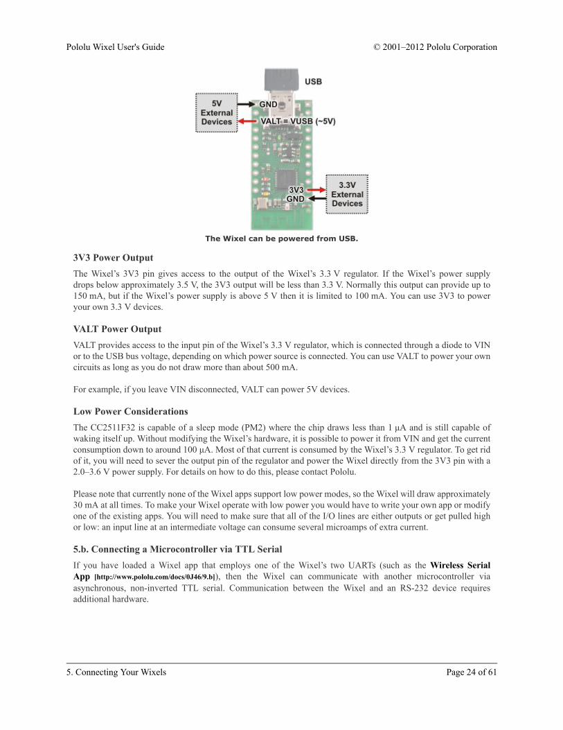
The Wixel can be powered from USB.
3V3 Power OutputThe Wixel’s 3V3 pin gives access to the output of the Wixel’s 3.3 V regulator. If the Wixel’s power supplydrops below approximately 3.5 V, the 3V3 output will be less than 3.3 V. Normally this output can provide up to150 mA, but if the Wixel’s power supply is above 5 V then it is limited to 100 mA. You can use 3V3 to poweryour own 3.3 V devices.
VALT Power OutputVALT provides access to the input pin of the Wixel’s 3.3 V regulator, which is connected through a diode to VINor to the USB bus voltage, depending on which power source is connected. You can use VALT to power your owncircuits as long as you do not draw more than about 500 mA.
For example, if you leave VIN disconnected, VALT can power 5V devices.
Low Power ConsiderationsThe CC2511F32 is capable of a sleep mode (PM2) where the chip draws less than 1 μA and is still capable ofwaking itself up. Without modifying the Wixel’s hardware, it is possible to power it from VIN and get the currentconsumption down to around 100 μA. Most of that current is consumed by the Wixel’s 3.3 V regulator. To get ridof it, you will need to sever the output pin of the regulator and power the Wixel directly from the 3V3 pin with a2.0–3.6 V power supply. For details on how to do this, please contact Pololu.
Please note that currently none of the Wixel apps support low power modes, so the Wixel will draw approximately30 mA at all times. To make your Wixel operate with low power you would have to write your own app or modifyone of the existing apps. You will need to make sure that all of the I/O lines are either outputs or get pulled highor low: an input line at an intermediate voltage can consume several microamps of extra current.
5.b. Connecting a Microcontroller via TTL SerialIf you have loaded a Wixel app that employs one of the Wixel’s two UARTs (such as the Wireless SerialApp [http://www.pololu.com/docs/0J46/9.b]), then the Wixel can communicate with another microcontroller viaasynchronous, non-inverted TTL serial. Communication between the Wixel and an RS-232 device requiresadditional hardware.
Pololu Wixel User's Guide © 2001–2012 Pololu Corporation
5. Connecting Your Wixels Page 24 of 61
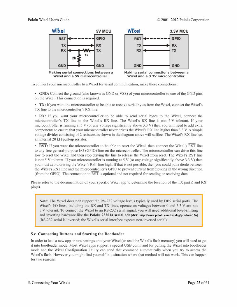
Making serial connections between aWixel and a 5V microcontroller.
Making serial connections between aWixel and a 3.3V microcontroller.
To connect your microcontroller to a Wixel for serial communication, make these connections:
• GND: Connect the ground (also known as GND or VSS) of your microcontroller to one of the GND pinson the Wixel. This connection is required.
• TX: If you want the microcontroller to be able to receive serial bytes from the Wixel, connect the Wixel’sTX line to the microcontroller’s RX line.
• RX: If you want your microcontroller to be able to send serial bytes to the Wixel, connect themicrocontroller’s TX line to the Wixel’s RX line. The Wixel’s RX line is not 5 V tolerant. If yourmicrocontroller is running at 5 V (or any voltage significantly above 3.3 V) then you will need to add extracomponents to ensure that your microcontroller never drives the Wixel’s RX line higher than 3.3 V. A simplevoltage divider consisting of 2 resistors as shown in the diagram above will suffice. The Wixel’s RX line hasan internal 20 kΩ pull-up resistor.
• RST: If you want the microcontroller to be able to reset the Wixel, then connect the Wixel’s RST lineto any free general-purpose I/O (GPIO) line on the microcontroller. The microcontroller can drive this linelow to reset the Wixel and then stop driving the line to release the Wixel from reset. The Wixel’s RST lineis not 5 V tolerant. If your microcontroller is running at 5 V (or any voltage significantly above 3.3 V) thenyou must avoid driving the Wixel’s RST line high. If that is not possible, then you could put a diode betweenthe Wixel’s RST line and the microcontroller’s GPIO to prevent current from flowing in the wrong direction(from the GPIO). The connection to RST is optional and not required for sending or receiving data.
Please refer to the documentation of your specific Wixel app to determine the location of the TX pin(s) and RXpin(s).
Note: The Wixel does not support the RS-232 voltage levels typically used by DB9 serial ports. TheWixel’s I/O lines, including the RX and TX lines, operate on voltages between 0 and 3.3 V are not5 V tolerant. To connect the Wixel to an RS-232 serial signal, you will need additional level-shiftingand inverting hardware like the Pololu 23201a serial adapter [http://www.pololu.com/catalog/product/126](RS-232 serial is inverted; the Wixel’s serial interface expects non-inverted serial).
5.c. Connecting Buttons and Starting the BootloaderIn order to load a new app or new settings onto your Wixel (or read the Wixel’s flash memory) you will need to getit into bootloader mode. Most Wixel apps support a special USB command for putting the Wixel into bootloadermode and the Wixel Configuration Utility can send that command automatically when you try to access theWixel’s flash. However you might find yourself in a situation where that method will not work. This can happenfor two reasons:
Pololu Wixel User's Guide © 2001–2012 Pololu Corporation
5. Connecting Your Wixels Page 25 of 61
• You accidentally loaded a malfunctioning program onto the Wixel that is incapable of responding to thespecial USB command.
• You loaded a program which uses a different type of USB interface or no USB interface. In this case,check the documentation of the app to see if there is a convenient way for getting the Wixel into bootloadermode.
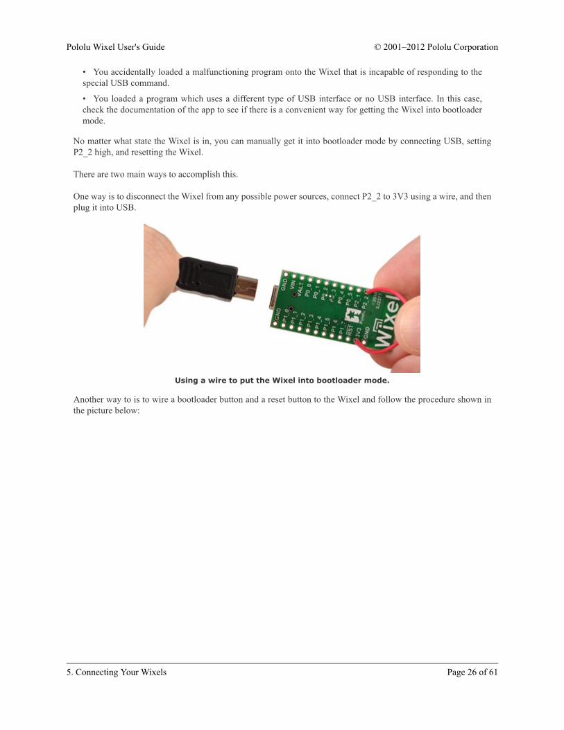
No matter what state the Wixel is in, you can manually get it into bootloader mode by connecting USB, settingP2_2 high, and resetting the Wixel.
There are two main ways to accomplish this.
One way is to disconnect the Wixel from any possible power sources, connect P2_2 to 3V3 using a wire, and thenplug it into USB.
Using a wire to put the Wixel into bootloader mode.
Another way to is to wire a bootloader button and a reset button to the Wixel and follow the procedure shown inthe picture below:
Pololu Wixel User's Guide © 2001–2012 Pololu Corporation
5. Connecting Your Wixels Page 26 of 61

Using pushbuttons to put the Wixel into bootloader mode.
Wixel on breadboard with a bootloader button and reset buttonconnected.
Pololu Wixel User's Guide © 2001–2012 Pololu Corporation
5. Connecting Your Wixels Page 27 of 61
6. Using a Virtual COM PortMost of the available Wixel apps implement a USB interface that consists of a single virtual COM (serial) port.This interface allows you to send and receive bytes from the Wixel in the same way you would send and receivebytes from any other serial port on your computer.
6.a. Determining the Port NameTo connect to a COM port, you usually have to know the name of the port.
In Windows, the port name will be something like “COM4” and you can determine the port name by selecting theWixel in the Wixel Configuration Utility and looking at the “Port Name” property displayed below. You can alsofind out the port name by looking the “Ports (COM & LPT)” list in your Device Manager.
Windows Tip: Besides having names like “COM5” and “COM6”, the virtual COM ports providedby the Wixel also have names like “\\.\USBSER000” and “\\.\USBSER001”. These names areassigned sequentially whenever a device with a virtual COM port is plugged in. If you only haveone device with a virtual COM port plugged into your computer, the name “\\.\USBSER000” willusually be assigned to it. These names will work with most programs that allow you to specifyarbitrary port names.
6.b. Using a Terminal ProgramThere are many free terminal programs available which are capable of sending and receiving bytes on a virtualCOM port. These programs include PuTTY [http://www.chiark.greenend.org.uk/~sgtatham/putty/] (Windows or Linux),Tera Term [http://ttssh2.sourceforge.jp/] (Windows), and Br@y Terminal [http://sites.google.com/site/terminalbpp/](Windows). Advanced users developing scripted applications may prefer the free terminal program kermit[http://www.columbia.edu/kermit/ck80.html]. To use any of these terminal programs with the Wixel, you must specifythe port name (see Section 6.a) and the baud rate. The baud rate may or may not affect anything; see yourapplication’s documentation. The characters you type will be transmitted on the programmer’s TX line. Bytesreceived by the programmer on the RX line will be displayed on the screen by the terminal program.
Typical terminal programs will allow you to choose several other settings besides the baud rate. If you are notsure what settings to use, then you should pick 8 data bits, 1 stop bit, no parity, and no flow control.
Typical terminal programs will not allow you to use the serial control signals, but Br@y terminal does. You canclick the “DTR” and “RTS” buttons to change the state of the DTR and RTS signals. The state of the CTS, CD,DSR, RI, DTR, and RTS signals are indicated by the colors of the corresponding buttons.
Pololu Wixel User's Guide © 2001–2012 Pololu Corporation
6. Using a Virtual COM Port Page 28 of 61

PuTTY is a free Windows terminal program that can send and receive bytes on aserial port.
If you need to send and receive non-ASCII bytes, you can use the Pololu Serial Transmitter Utility forWindows [http://www.pololu.com/docs/0J23] or Br@y Terminal.
6.c. Writing PC Software to Use a Serial PortYou can write your own computer program that communicates with a serial port. The freely available Microsoft.NET framework contains a SerialPort [http://msdn.microsoft.com/en-us/library/system.io.ports.serialport.aspx] class thatmakes it easy to read and write bytes from a serial port. Here is some example C# .NET code that uses a serialport:
// Choose the port name and the baud rate.System.IO.Ports.SerialPort port = new System.IO.Ports.SerialPort("COM4", 115200);
// Connect to the port.port.Open();
// Transmit two bytes on the TX line: 1, 2port.Write(new byte[]{1, 2}, 0, 2);
// Wait for a byte to be received on the RX line.int response = port.ReadByte();
// Show the user what byte was received.MessageBox.Show("Received byte: " + response);
// Disconnect from the port so that other programs can use it.port.Close();
Pololu Wixel User's Guide © 2001–2012 Pololu Corporation
6. Using a Virtual COM Port Page 29 of 61
7. Ensuring a Good Radio SignalHere are some tips for improving the quality of the radio signals sent between a pair of Wixels:
• Reduce the distance between the Wixels, if possible.
• Try different frequencies. Most Wixel apps that use the radio have a radio_channel parameter thatdetermines what frequency will be used. By switching to a different channel you might be able to avoidinterference from other nearby 2.4 GHz radios. You might even want to buy a spectrum analyzer such asthe Wi-Spy [http://www.metageek.net/products/wi-spy/] to find out which frequencies in your area have the leastactivity.
• Remove objects that are very close to the Wixel’s antenna. For example, if the Wixel has no header pinsinstalled and it is resting flat on your desk, find a way to get the Wixel at least an inch or two above the desk.
• Reduce obstructions between the two Wixels. Many objects can interfere with 2.4 GHz radio waves,including walls, trees, people and anything with water in it.
• Try different Wixel orientations. The Wixel’s antenna sends and receives better in some directions thanothers.
Pololu Wixel User's Guide © 2001–2012 Pololu Corporation
7. Ensuring a Good Radio Signal Page 30 of 61

8. Schematic DiagramThe schematic diagram of the Wixel is shown below:
The schematic also available as a printable pdf [http://www.pololu.com/file/download/wixel_schematic.pdf?file_id=0J463] (51k pdf).
Pololu Wixel User's Guide © 2001–2012 Pololu Corporation
8. Schematic Diagram Page 31 of 61

Wireless PC control of a 3pi robot using apair of Wixels.
Together, the USB Adapter A to Mini-Band a Pololu Wixel wireless module can
make a compact USB dongle.
9. Wixel AppsThis section describes the available Wixel apps.
9.a. Example App: Blink LEDThis is an example app that blinks the red LED with a configurable period. See Section 3.d for a tutorial on usingthis app.
Download link: example_bink_led_v1.0.wxl [http://www.pololu.com/file/download/example_blink_led_v1.0.wxl?file_id=0J449] (11k wxl)
9.b. Wireless Serial AppOverviewThis app allows you to connect two Wixels together to make awireless, bidirectional, lossless serial link. It uses an RF bit rateof 350 kbps, is capable of carrying up to 10 KB of payload dataper second, and can reach a range of approximately 50 feet(under typical conditions indoors). You can also use it to turnone Wixel into a USB-to-TTL serial adapter.
This app can run on multiple pairs of Wixels as long as each pairoperates on a different radio channel (the channels should beseparated by 2 to avoid interference).
This app is designed for pairs of Wixels; it will not workproperly if three or more Wixels are broadcasting on the sameradio channel.
Installation InstructionsDownload Wireless Serial App v1.3 [http://www.pololu.com/file/download/wireless-serial-v1.3.wxl?file_id=0J484] (26k wxl). Open itwith the Wixel Configuration Utility, choose your parameters,and then write it to two Wixels. See Section 4 for moreinformation on how this is done.
Pololu Wixel User's Guide © 2001–2012 Pololu Corporation
9. Wixel Apps Page 32 of 61

Default PinoutPin Function
P1_0 DTR general-purpose output pin
P1_1 RTS general-purpose output pin
P1_2 DSR general-purpose input pin
P1_3 CD general-purpose input pin
P1_5 PA_PD radio transmit debug output
P1_6 TX transmits serial data (0–3.3 V)
P1_7 RX receives serial data (0–3.3 V, not 5 V tolerant)
P0_0 Arduino DTR for wireless Arduino programming when used with the Wixel shield
DescriptionThis device appears to the USB host as a Virtual COM Port (with USB product ID 0x2200). If you are usingWindows, you should see an entry labeled “Wixel” in your Device Manager in the “Ports (COM & LPT)” categorywhile the app is running.
There are three basic serial modes that can be selected:
1. USB-to-Radio: Serial bytes from the USB virtual COM port get sent to the radio and vice versa.
2. UART-to-Radio: Serial bytes from the UART’s RX line get sent to the radio and bytes from the radio getsent to the UART’s TX line.
3. USB-to-UART: Just like a normal USB-to-TTL serial adapter, bytes from the virtual COM port get senton the UART’s TX line and bytes from the UART’s RX line get sent to the virtual COM port.
You can select which serial mode you want to use by setting the serial_mode parameter to the appropriate number(from the list above) or you can leave the serial mode at 0 (which is the default). If the serial_mode is 0, then theWixel will automatically choose a serial mode based on how it is being powered as described in the table below,and it will switch between the different serial modes on the fly.
Auto-Detect Serial Mode(serial_mode = 0)
Power Source Serial Mode
USB only USB-to-Radio
VIN only UART-to-Radio
USB and VIN USB-to-UART
The RX pin has an internal 20 kΩ pull-up resistor.
The PA_PD pin (P1_5) is a debugging output that goes low while the Wixel is transmitting a packet on the radio.
The serial data format used by this app is 8 data bits, one stop bit, with no parity, which is often expressed 8-N-1.The data is non-inverted, so 0 V represents 0 and 3.3 V represents 1.
Pololu Wixel User's Guide © 2001–2012 Pololu Corporation
9. Wixel Apps Page 33 of 61

Indicator LEDsThe green LED behaves as described in Section 1.a, and also flickers when there is data transferred over USB.
The yellow LED represents the state of the radio. If the Wixel is in a serial mode where the radio is not used,the yellow LED will be off. Otherwise, the yellow LED turns on and off slowly until radio communication isestablished for the first time, after which it blinks briefly once per second and flickers whenever data is sent orreceived via the radio.
The red LED indicates errors. The red LED will flash briefly if a byte is received on the UART’s RX line that hadto be discarded because the receive buffers were full. The red LED will turn on when a framing error occurs onthe RX line and will stay on until the RX line goes high.
Control SignalsIn addition to relaying bidirectional serial data, this app also relays the values of four control signals: DTR, RTS,DSR, and CD. The names of these control signals come from the RS-232 protocol, but in this app they do notactually have the same role as they have in that protocol: they are general purpose digital control signals that cancarry any kind of data that you want them to, as long as that data changes slowly (on the order of 5 Hz or slower)and is limited to two bits in each direction.
In USB-to-Radio mode, the DTR and RTS signals from USB are transmitted wirelessly to the other Wixel, whilethe control signals wirelessly received from the other Wixel are relayed to USB as DSR and CD.
In UART-to-Radio mode, the DSR and CD signals from the digital input pins are transmitted wirelessly to theother Wixel, while the control signals wirelessly received from the other Wixel are relayed to the DTR and RTSoutput pins.
In USB-to-UART mode, the DTR and RTS signals from USB are relayed to the corresponding output pins, whilethe values of the DSR and CD input pins are relayed to USB.
If two Wixels are communicating wirelessly with each other and both are in UART-to-Radio mode or both arein USB-to-Radio mode, then the correspondence between the control lines is as follows: DSR on one Wixelcorresponds to DTR on the other Wixel, while RTS on one Wixel corresponds to CD on the other Wixel.
The default configuration of this app (as shown in the table above) gives the Wixel two inverted output pins (DTRand RTS), and two inverted input pins (DSR and CD). These pins are inverted, which means that a logical valueof 0 corresponds to high voltage (usually 3.3 V), while a logical value of 1 corresponds to 0 V (GND).
By changing the configuration parameters (see below), you can disable these signals, reassign them to differentI/O lines, or add non-inverted inputs and outputs.
Any pin configured as an input will have an internal 20 kΩ pull-up resistor unless it is assigned to P1_0 or P1_1,which do not have pull-up or pull-down resistors.
You do not have to connect anything to the control signal pins in order to send and receive serialdata. These pins are optional.
General Parameters• serial_mode: Selects the serial mode (1–3, see list above) or auto-detect serial mode (0). The default is 0.
Pololu Wixel User's Guide © 2001–2012 Pololu Corporation
9. Wixel Apps Page 34 of 61
• baud_rate: The baud rate to use for the UART, in bits per second. The default is 9600. We recommend notexceeding 115200. This parameter has no effect on serial communication over the virtual COM port (USB).
• radio_channel: The channel number is from 0 to 255 and determines which frequency to broadcaston. The default is 128. Wixels must be on the same channel to communicate with each other. To avoidinterference, Wixels that aren’t supposed to talk to each other should be at least 2 channels away from eachother. For example, you could have one pair of Wixels on channel 128 and another pair on 130.
• framing_error_ms: The approximate number of milliseconds to disable the UART’s receiver for afterencountering a framing error on the RX line. Valid values are 0–250. The default is 0, which means that theUART’s receiver will not get disabled after a framing error.
Pin Assignment ParametersThe following parameters can be used to reassign the control signals to different pins on the Wixel. The value ofeach parameter must be the number of an unused pin on the Wixel. The number can be computed by multiplyingthe first digit in the pin name by 10 and adding it to the second digit in the pin name. For example, if you wantedto assign the DSR pin to P1_2, you would set nDSR_pin to 12. To disable a signal (assign it to no pin), set thecorresponding parameter to -1.
• nDTR_pin: The pin assignment for the inverted DTR output. The default is 10 (P1_0).
• nRTS_pin: The pin assignment for the inverted RTS output. The default is 11 (P1_1).
• nDSR_pin: The pin assignment for the inverted DSR input. The default is 12 (P1_2).
• nCD_pin: The pin assignment for the inverted CD input. The default is 13 (P1_3).
• DTR_pin: The pin assignment for the non-inverted DTR output. The default is -1 (disabled).
• RTS_pin: The pin assignment for the non-inverted RTS output. The default is -1 (disabled).
• DSR_pin: The pin assignment for the non-inverted DSR input. The default is -1 (disabled).
• CD_pin: The pin assignment for the non-inverted CD input. The default is -1 (disabled).
• arduino_DTR_pin: The pin assignment for an output for wireless Arduino programming when used withthe Wixel shield [http://www.pololu.com/catalog/product/2500]. The default is 0 (P0_0).
You should not simultaneously enable the non-inverted and inverted input for the same signal. Specifically, eithernCD_pin or CD_pin should be -1 and either nDSR_pin or DSR_pin should be -1.
Example Uses1. This application can be used to make a wireless serial link between two microcontrollers, with no USBinvolved (except for initially configuring the Wixels). To do this, use the UART-to-Radio mode on bothWixels.
2. This application can be used to make a wireless serial link between a computer and a microcontroller.Use USB-to-Radio mode on the Wixel that is connected to the computer and use UART-to-Radio mode onthe Wixel that is connected to the microcontroller. If you are powering both Wixels in the usual way, youshould be able to use auto-detect serial mode (serial_mode = 0).
3. If you are doing option 2 above and using the the auto-detect serial mode (serial_mode = 0), thenyou have the option to (at any time) plug a USB cable directly into the Wixel that is connected to yourmicrocontroller to establish a more direct (wired) serial connection with the microcontroller. (You would, ofcourse, have to tell your computer to switch to the other COM port when you do this.)
Pololu Wixel User's Guide © 2001–2012 Pololu Corporation
9. Wixel Apps Page 35 of 61

CaveatsData will be lost if the Wixel receives bytes on the RX line faster than the radio can convey them to the otherWixel. If you have trouble, try reducing the amount of data sent to the RX line by lowering the baud rate or addingdelays to your microcontroller’s code.
Caution: The Wixel’s I/O lines are not 5V tolerant. You must use level-shifters, diodes, or voltagedividers to connect the Wixel to outputs from 5V systems. Also, avoid drawing more current from anI/O line than it can provide (see the discussion of P1_0 and P1_1 in Section 1.a). Avoid connectingmultiple output pins together.
The Wixel does not support the RS-232 voltage levels typically used by DB9 serial ports. The Wixel’sI/O lines, including the RX and TX lines, operate on voltages between 0 and 3.3 V. To connect theWixel to an RS-232 serial signal, you will need additional level-shifting and inverting hardware likethe Pololu 23201a serial adapter [http://www.pololu.com/catalog/product/126] (RS-232 serial is inverted;the Wixel’s serial interface expects non-inverted serial).
Versions• Wireless Serial App v1.3 [http://www.pololu.com/file/download/wireless-serial-v1.3.wxl?file_id=0J484] (26k wxl),released 2011-06-20: Added the framing_error_ms parameter and the corresponding feature for disablingthe UART’s receiver after a framing error. Changed the behavior of the red and yellow LEDs; in previousversions the red LED was off and the yellow LED simply indicated the presence of VIN power.
• Wireless Serial App v1.2 [http://www.pololu.com/file/download/wireless_serial_v1.2.wxl?file_id=0J468] (24k wxl),released 2011-04-06: Added support for control signals. As a result, the radio protocol used is NOTcompatible with earlier versions. Also fixed a glitch on the TX line that occurred upon power-up or reset.Added blinking behavior to the green LED to indicate USB data transfer.
• Wireless Serial App v1.1 [http://www.pololu.com/file/download/wireless_serial_v1.1.wxl?file_id=0J461] (18k wxl),released 2011-03-23: Improved the radio protocol to fix a problem in v1.0 where if one Wixel resets but theother Wixel does not, then (depending on the state of the other Wixel) there is a 50% probability that the nextradio packet sent in either direction will be ignored by the receiver.
• Wireless Serial App v1.0 [http://www.pololu.com/file/download/wireless_serial_v1.0.wxl?file_id=0J447] (18k wxl),released 2011-03-22: Initial release.
Versions Configured for the Wixel Shield for ArduinoThese are special versions of the app that have the same code as the corresponding standard versions, but havedifferent settings so that they will work well with the Wixel Shield for Arduino [http://www.pololu.com/catalog/product/2500]. The default baud_rate was changed to 115200, which is the baud rate used by the Arduino Uno’s[http://www.pololu.com/catalog/product/2191] bootloader. All the pin assignment parameters were set to -1 (disabled)except arduino_DTR_pin, which was left at 0 (P0_0). The framing_error_ms parameter was set to 5. The onlyparameters of these apps that can be modified by the user are the radio_channel parameter and baud_rateparameter. For more information about configuring this version, please see the Section 2.c of the Wixel ShieldUser’s Guide [http://www.pololu.com/docs/0J47].
• Wireless Serial App (version 1.3) configured for the Wixel Shield for Arduino[http://www.pololu.com/file/download/wireless-serial-v1.3-shield.wxl?file_id=0J485] (25k wxl)
Pololu Wixel User's Guide © 2001–2012 Pololu Corporation
9. Wixel Apps Page 36 of 61
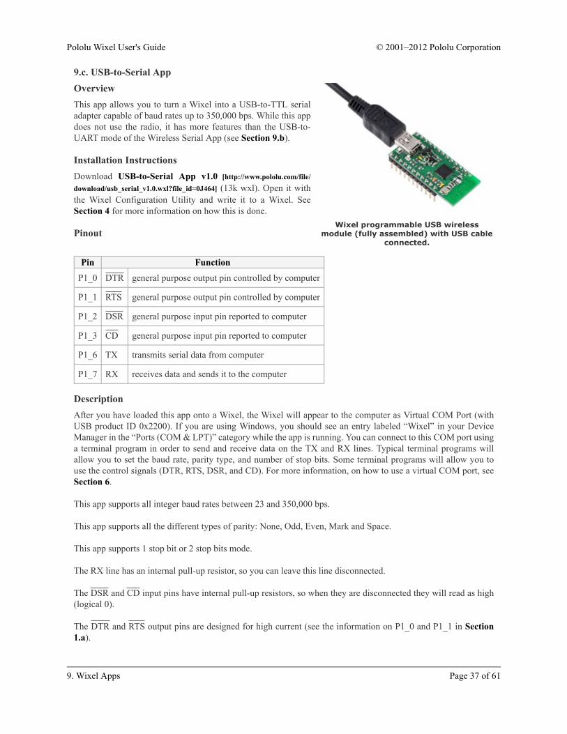
Wixel programmable USB wirelessmodule (fully assembled) with USB cable
connected.
9.c. USB-to-Serial AppOverviewThis app allows you to turn a Wixel into a USB-to-TTL serialadapter capable of baud rates up to 350,000 bps. While this appdoes not use the radio, it has more features than the USB-to-UART mode of the Wireless Serial App (see Section 9.b).
Installation InstructionsDownload USB-to-Serial App v1.0 [http://www.pololu.com/file/download/usb_serial_v1.0.wxl?file_id=0J464] (13k wxl). Open it withthe Wixel Configuration Utility and write it to a Wixel. SeeSection 4 for more information on how this is done.
Pinout
Pin Function
P1_0 DTR general purpose output pin controlled by computer
P1_1 RTS general purpose output pin controlled by computer
P1_2 DSR general purpose input pin reported to computer
P1_3 CD general purpose input pin reported to computer
P1_6 TX transmits serial data from computer
P1_7 RX receives data and sends it to the computer
DescriptionAfter you have loaded this app onto a Wixel, the Wixel will appear to the computer as Virtual COM Port (withUSB product ID 0x2200). If you are using Windows, you should see an entry labeled “Wixel” in your DeviceManager in the “Ports (COM & LPT)” category while the app is running. You can connect to this COM port usinga terminal program in order to send and receive data on the TX and RX lines. Typical terminal programs willallow you to set the baud rate, parity type, and number of stop bits. Some terminal programs will allow you touse the control signals (DTR, RTS, DSR, and CD). For more information, on how to use a virtual COM port, seeSection 6.
This app supports all integer baud rates between 23 and 350,000 bps.
This app supports all the different types of parity: None, Odd, Even, Mark and Space.
This app supports 1 stop bit or 2 stop bits mode.
The RX line has an internal pull-up resistor, so you can leave this line disconnected.
The DSR and CD input pins have internal pull-up resistors, so when they are disconnected they will read as high(logical 0).
The DTR and RTS output pins are designed for high current (see the information on P1_0 and P1_1 in Section1.a).
Pololu Wixel User's Guide © 2001–2012 Pololu Corporation
9. Wixel Apps Page 37 of 61
The control signals are all inverted, which means that a logical 0 corresponds to a high voltage (3.3 V) and alogical 1 corresponds to a low voltage (0 V).
This app will discard bytes received on the RX line that have framing errors or parity errors, and it will also throwout bytes if there is an RX buffer overrun. An RX buffer overrun should not happen if you are using a baud rateof 350,000 bps or less.
Example Uses• The TX line can be used to send commands to a microcontroller or other serial device.
• The RX line can be used to receive data from a microcontroller or other serial device.
• The DTR and RTS lines are general-purpose digital outputs that can be used to control something (suchas an LED) from a computer.
• The DSR and CD lines are general-purpose digital inputs that can be connected to a sensor or other circuitand read from a computer.
Caveats• The CC2511’s UARTs do not actually support 1.5 stop bits, so if you try to set the number of stop bits to1.5, this app will use 1 stop bit instead.
• The CC2511’s UARTs do not support having 2 stop bits very well, so if you set the number of stop bits to2, this app may fail to detect framing errors that occur during the second stop bit. Also, the next byte receivedafter the framing error occurred may be discarded even if that byte is valid. This problem only applies toreceiving bytes on the RX line; this app has no problem transmitting bytes on the TX line with 2 stop bits.
Caution: The Wixel’s I/O lines are not 5V tolerant. You must use level-shifters, diodes, or voltagedividers to connect the Wixel to outputs from 5V systems. Also, avoid drawing more current from anI/O line than it can provide (see the discussion of P1_0 and P1_1 in Section 1.a). Avoid connectingmultiple output pins together.
The Wixel does not support the RS-232 voltage levels typically used by DB9 serial ports. The Wixel’sI/O lines, including the RX and TX lines, operate on voltages between 0 and 3.3 V. To connect theWixel to an RS-232 serial signal, you will need additional level-shifting and inverting hardware likethe Pololu 23201a serial adapter [http://www.pololu.com/catalog/product/126] (RS-232 serial is inverted;the Wixel’s serial interface expects non-inverted serial).
9.d. I/O Repeater AppOverviewThis app allows you to wirelessly extend the reach of your microcontroller’s I/O lines up to 50 feet using two ormore Wixels. An input pin on one Wixel can be mapped to an output pin on another Wixel. When the input pinreads high, the output pin will be driven high (3.3 V) and when the input pin reads low, the output pin will bedriven low (0 V). Each Wixel can have up to 15 input pins, 15 output pins, or a mixture of input and output pins.Each input pin can map to one or more output pins on one or more Wixels.
Pololu Wixel User's Guide © 2001–2012 Pololu Corporation
9. Wixel Apps Page 38 of 61

Installation InstructionsDownload I/O Repeater App v1.3 [http://www.pololu.com/file/download/io_repeater_v1.3.wxl?file_id=0J562] (22k wxl). Open it withthe Wixel Configuration Utility, choose your settings, and writeit to two or more Wixels. See Section 4 for more information onhow this is done.
DescriptionThe following 15 pins on each Wixel can be used as inputs oroutputs (or be disabled):
• All the pins on Port 0: P0_0, P0_1, P0_2, P0_3, P0_4,P0_5.
• All the pins on Port 1: P1_0, P1_1, P1_2, P1_3, P1_4, P1_5, P1_6, P1_7.
• Pin P2_1 (the red LED pin).
The behavior of each pin is determined by its link ID, which is a parameter that you can set individually for eachpin on each Wixel using the Wixel Configuration Utility. A link ID of 0 means the pin will be disabled (it will bean input but its input value will not have any effect). A negative link ID between -1 and -127 means that the pinwill be a digital input and its value will be transmitted over the radio. A positive link ID between 1 and 127 meansthat the pin will be a digital output and its output value will be determined by the input value of the pin with theopposite (negated) link ID on another Wixel. For example, if the P1_3 pin on one Wixel has a link ID of -13, thenit will be a digital input and its value will be reflected on all the output pins that have a link ID of 13 on all theother Wixels. Input pins do not have any effect on output pins that are on the same Wixel.
If a Wixel is running this app and has one or more pins configured to be inputs, then it will transmit a single radiopacket every 7–10 ms that contains input values and link IDs of all of its inputs. Any other Wixel that successfullyreceives this packet will process it and use it to update the state of its output pins.
This app will work with more than two Wixels on the same radio channel. In that case, make sure that you do nothave multiple input pins on different Wixels with the same link ID: otherwise, the corresponding output pin(s)will change state unpredictably whenever there is a conflict between the different input pins. It is OK to havemuliple output pins with the same link ID.
Every pin configured as an input has an internal 20 kΩ pull-up resistor except P1_0 and P1_1, which float whenthey are inputs. This means that if you leave the input pin disconnected, it will be pulled high by default.
Each output pin will drive low (0 V) by default before any radio packets are received that change its state.
After you have loaded this app onto a Wixel, the Wixel will appear to the computer as Virtual COM Port (withUSB product ID 0x2200). If you are using Windows, you should see an entry labeled “Wixel” in your DeviceManager in the “Ports (COM & LPT)” category while this app is running. You can not send or receive data on thisCOM port. Its only purpose is to let the Wixel Configuration Utility easily get the Wixel into bootloader mode.
Parameters• radio_channel: The channel number is from 0 to 255 and determines which frequency to broadcaston. The default is 128. Wixels must be on the same channel to communicate with each other. To avoidinterference, Wixels that aren’t supposed to talk to each other should be at least 2 channels away from eachother. For example, you could have one pair of Wixels on channel 128 and another pair on 130.
• Pm_n_link: The link ID of pin Pm_n where m is the port number (0–2) and n is the pin number (0–7).
Pololu Wixel User's Guide © 2001–2012 Pololu Corporation
9. Wixel Apps Page 39 of 61

Default SettingsThe default settings are:
Pin Link ID Function
P0_0 -1 Input with pull-up resistor.
P2_1 (red LED pin) 1 Output linked to P0_0 on the other Wixel.
Therefore, if you load this app onto two Wixels using the default settings, they should behave as follows: Ifnothing is connected to either Wixel’s P0_0 line, the red LEDs on both Wixels will be on. If you connect theP0_0 line of one Wixel to GND using a wire, then you should see the red LED on the other Wixel turn off. Thisdemonstrates the basic operation of the app.
Example Uses• A Wixel output pin can be used to control an LED. Be sure to use an appropriate current-limiting resistorin series with the LED (e.g. 1 kΩ)
• A Wixel input pin can be used to read the state of a button or switch. Connect the button or switch betweenthe input pin and GND, so that when the switch is open the pin will read high, and when the switch is closedthe pin will read low.
• A Wixel output pin can be connected to an input pin on another microcontroller.
• A Wixel input pin can be connected to an output pin on another microcontroller. The output must not driveto a voltage higher than 3.3 V. If your microcontroller is running at 5 V you could get around this by using adiode or putting your output pin into open-collector mode (never drive high).
Caveats• A change on an input pin will usually be reflected on the corresponding output pin(s) within 10–100 ms,but every radio packet has a chance of being lost so there is no guaranteed latency. Therefore, this app is onlysuitable for very low-speed digital signals such as the signal from a pushbutton or the signal used to controlan LED. This app is not suitable for PWM or RC servo signals.
• This app uses digital I/O which means that every reading is transmitted as a 0 or 1. This app does notsupport analog voltages.
Caution: The Wixel’s I/O lines are not 5V tolerant. You must use level-shifters, diodes, or voltagedividers to connect the Wixel to outputs from 5V systems. Also, avoid drawing more current from anI/O line than it can provide (see the discussion of P1_0 and P1_1 in Section 1.a). Avoid connectingmultiple output pins together.
Versions• I/O Repeater App v1.3 [http://www.pololu.com/file/download/io_repeater_v1.3.wxl?file_id=0J562] (22k wxl),released 2012-07-03: Adds randomness to the radio packet transmission timing to prevent two transmittingWixels from being synchronized if they start up at the same time.
• I/O Repeater App v1.1 [http://www.pololu.com/file/download/io_repeater_v1.1.wxl?file_id=0J500] (20k wxl),released 2011-07-26: Fixes a bug in v1.0 which prevented P1_6 and P1_7 from being used as outputs.
• I/O Repeater App v1.0 [http://www.pololu.com/file/download/io_repeater_v1.0.wxl?file_id=0J465] (18k wxl),released 2011-03-25: Initial release.
Pololu Wixel User's Guide © 2001–2012 Pololu Corporation
9. Wixel Apps Page 40 of 61
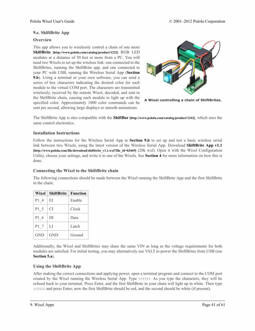
A Wixel controlling a chain of ShiftBrites.
9.e. ShiftBrite AppOverviewThis app allows you to wirelessly control a chain of one moreShiftBrite [http://www.pololu.com/catalog/product/1222] RGB LEDmodules at a distance of 50 feet or more from a PC. You willneed two Wixels to set up the wireless link: one connected to theShiftBrites, running the ShiftBrite app, and one connected toyour PC with USB, running the Wireless Serial App (Section9.b). Using a terminal or your own software, you can send aseries of hex characters indicating the desired color for eachmodule to the virtual COM port. The characters are transmittedwirelessly, received by the remote Wixel, decoded, and sent tothe ShiftBrite chain, causing each module to light up with thespecified color. Approximately 1000 color commands can besent per second, allowing large displays or smooth animations.
The ShiftBrite App is also compatible with the ShiftBar [http://www.pololu.com/catalog/product/1242], which uses thesame control electronics.
Installation InstructionsFollow the instructions for the Wireless Serial App in Section 9.b to set up and test a basic wireless seriallink between two Wixels, using the latest version of the Wireless Serial App. Download ShiftBrite App v1.1[http://www.pololu.com/file/download/shiftbrite_v1.1.wxl?file_id=0J469] (20k wxl). Open it with the Wixel ConfigurationUtility, choose your settings, and write it to one of the Wixels. See Section 4 for more information on how this isdone.
Connecting the Wixel to the ShiftBrite chainThe following connections should be made between the Wixel running the ShiftBrite App and the first ShiftBritein the chain:
Wixel ShiftBrite Function
P1_4 EI Enable
P1_5 CI Clock
P1_6 DI Data
P1_7 LI Latch
GND GND Ground
Additionally, the Wixel and ShiftBrites may share the same VIN as long as the voltage requirements for bothmodules are satisfied. For initial testing, you may alternatively use VALT to power the ShiftBrites from USB (seeSection 5.a).
Using the ShiftBrite AppAfter making the correct connections and applying power, open a terminal program and connect to the COM portcreated by the Wixel running the Wireless Serial App. Type ffffff. As you type the characters, they will beechoed back to your terminal. Press Enter, and the first ShiftBrite in your chain will light up in white. Then typeff0000 and press Enter; now the first ShiftBrite should be red, and the second should be white (if present).
Pololu Wixel User's Guide © 2001–2012 Pololu Corporation
9. Wixel Apps Page 41 of 61
To shift out multiple color commands at once, for example when you want to set the colors of the entire chain,type a series of single-color commands without pressing Enter, then press Enter once to apply them all.
Parameters• radio_channel: The channel number is from 0 to 255 and determines which frequency to broadcaston. The default is 128. Wixels must be on the same channel to communicate with each other. To avoidinterference, Wixels that aren’t supposed to talk to each other should be at least 2 channels away from eachother. For example, you could have one pair of Wixels on channel 128 and another pair on 130.
• input_bits: The number of bits per channel that you would like to use to send color information. Theallowed values are 1 to 16, and the default is 8, which corresponds to colors represented by 6-digit hexvalues. However, the ShiftBrite supports 10 bits of resolution, so choose a value of 10 to make use of its fulldynamic range. In this case, you must send 9 digits to set a color. For example, 3ff3ff3ff is the brightestpossible white and 001000000 is the dimmest possible red. Other values for this parameter might be usefulin special situations (e.g. 4 bits of resolution lets you specify a full color in three bytes, such as f00 for red,which allows for a higher update rate).
• echo_on: Set to 0 to disable echoing of every character sent. While echoes are useful for debugging, youmight want to disable them for the highest possible speed.
Data FormatThe data consists of a series of red, green, and blue (RGB) values, as ASCII hex strings. Each value containsfrom 1 to 4 characters, depending on the value of input_bits, specifying a number from 0 to 2input_bits-1. Whena complete set of R, G, and B values has been received, the values are multiplied or divided by the appropriatefactor to match the 10-bit ShiftBrite data format and shifted out to the ShiftBrite chain. An Enter character (ASCII10 or 13) causes the Latch pin to be toggled, instantly setting each ShiftBrite to its new color.
Tips• The yellow LED is normally on, and flickers whenever data is received from the radio, which might beuseful for debugging your wireless connection.
• You can use wires with pre-crimped terminals [http://www.pololu.com/catalog/category/71] and crimpconnector housings [http://www.pololu.com/catalog/category/70] to make a custom cable between the Wixel andthe ShiftBrite chain.
Versions• Shiftbrite App v1.1 [http://www.pololu.com/file/download/shiftbrite_v1.1.wxl?file_id=0J469] (20k wxl), released2011-04-06: Changed the yellow LED to be normally on, but flicker whenever data is received from theradio. This version is only compatible with Wireless Serial App v1.2 and later.
• Shiftbrite App v1.0 [http://www.pololu.com/file/download/shiftbrite_v1.0.wxl?file_id=0J466] (18k wxl), released2011-03-28: Initial release. In this version, the yellow LED starts off and turns on after the first Enter isreceived. This version is only compatible with Wireless Serial App versions 1.0 and 1.1.
Pololu Wixel User's Guide © 2001–2012 Pololu Corporation
9. Wixel Apps Page 42 of 61

Wireless tilt mouse made with twoWixels and an accelerometer.
9.f. Wireless Tilt Mouse AppOverviewThis app allows you to make a wireless tilt mouse for yourcomputer. By tilting the mouse, you can control the position ofthe mouse cursor. The mouse also supports two buttons forclicking.
This app requires two Wixels: a transmitter and a receiver. Thetransmitter Wixel detects a tilt using an accelerometer andwirelessly transmits that information to the receiver Wixel,which relays it to the computer as mouse movements. Thereceiver appears to the computer as a standard USB HumanInterface Device (HID); after the Wixels have been configured,no driver installation is necessary to use the mouse.
Parts NeededThere are many different ways to build this project. Here are the parts we used:
• Wixel Pair (Fully Assembled) + USB Cable [http://www.pololu.com/catalog/product/1338]
• MMA7361L 3-Axis Accelerometer ±1.5/6g [http://www.pololu.com/catalog/product/1246]
• 3-AAA Battery Holder, Enclosed with Switch [http://www.pololu.com/catalog/product/1147] and 3 AAAbatteries
• 270-Point Breadboard [http://www.pololu.com/catalog/product/350]
• Mini Pushbutton Switches [http://www.pololu.com/catalog/product/1400]
You will need wires and connectors to make the electrical connections. We suggest our jumper wire kits[http://www.pololu.com/catalog/category/29] or premium jumper wires [http://www.pololu.com/catalog/category/65].
You will need a soldering iron [http://www.pololu.com/catalog/category/5] to solder the included header pins into theaccelerometer.
The pushbuttons are optional, and any normally-open (NO) pushbutton or switch will work. If you want to haveboth a left mouse button and a right mouse button you should get two pushbuttons. Note that only one button (onP1_2) is shown in the picture above.
Pinout of Transmitter WixelPin Function
P0_1 analog input for vertical mouse speed
P0_2 analog input for horizontal mouse speed
P1_2 left mouse button input, internally pulled high
P1_7 right mouse button input, internally pulled high
Wixel ConfigurationDownload the Wireless Tilt Mouse App [http://www.pololu.com/file/download/wireless_tilt_mouse_v1.0.wxl?file_id=0J470](26k wxl). Open it with the Wixel Configuration Utility, choose your settings, and write it to the transmitter Wixel.
Pololu Wixel User's Guide © 2001–2012 Pololu Corporation
9. Wixel Apps Page 43 of 61

The transmitter Wixel should now appear to your computer as a USB virtual COM port (with USB product ID0x2200). You can not send or receive data on this COM port. Its only purpose is to let the Wixel ConfigurationUtility easily get the transmitter Wixel into bootloader mode when the transmitter Wixel is connected to thecomputer via USB.
Download the Wireless Tilt Mouse Receiver App [http://www.pololu.com/file/download/wireless_tilt_mouse_receiver_v1.0.wxl?file_id=0J471] (15k wxl). Open it with the Wixel Configuration Utility, chooseyour settings, and write it to the receiver Wixel. The receiver Wixel should now appear to your computer as aHuman Interface Device. If you are using Windows there should be a new entry entitled “HID-compliant mouse”in your Device Manager in the “Mice and other pointing devices” section. The receiver will also show up as akeyboard, but it does not use that interface.
The Wixel Configuration Utility does not yet detect Wixels with USB HID interfaces. Therefore,if you need to reconfigure your receiver Wixel, you will need to manually get it into bootloadermode (set pin P2_2 high and reset – although this app monitors P2_2 all the time so the reset is notstrictly necessary).
AssemblyWith the battery pack switched off, connect power for the transmitter Wixel. The black wire from the battery packshould connect to a GND pin on the Wixel. The red wire from the battery pack should connect to VIN. To test theconnection, turn on the battery pack: the transmitter Wixel’s yellow LED should turn on. Remember to turn offthe battery pack while you are making connections.
Connect the GND of the Wixel to the GND (ground) pin of the accelerometer. Connect power for theaccelerometer. The MMA7361L accelerometer we used can run off of 3.3 V and draws relatively little current, sowe powered it from the Wixel’s 3V3 line by connecting 3V3 to the accelerometer’s VDD.
Make any connections necessary to enable your accelerometer. For the MMA7361L, we connected SLP to VDD.
Choose which axis of the accelerometer will control the mouse cursor’s horizontal movement and connect itsoutput to the transmitter Wixel’s P0_2 pin. If your accelerometer is oriented as shown in the picture above, youshould use the Y axis.
Choose which axis of the accelerometer will control the mouse cursor’s vertical movement and connect its outputto the transmitter Wixel’s P0_1 pin. If your accelerometer is oriented as shown in the picture above, you shoulduse the X axis.
Connect a normally-open (NO) pushbutton between the transmitter Wixel’s P1_2 pin and GND. This will be theleft mouse button. The P1_2 input line has an internal pull-up resistor, so the voltage on that line should be high(3.3 V) when the button is not pressed. When the button is pressed, the voltage should go low (0 V).
In the same manner, connect a pushbutton between the transmitter Wixel’s P1_7 pin and GND. This will be theright mouse button.
ParametersBoth the transmitter and receiver app have a parameter called radio_channel. The channel number is from 0 to255 and determines which frequency to broadcast on. The default is 128. The transmitter and receiver must beon the same channel to talk to each other. To avoid interference, Wixels that aren’t supposed to talk to each other
Pololu Wixel User's Guide © 2001–2012 Pololu Corporation
9. Wixel Apps Page 44 of 61
should be at least 2 channels away from each other. For example, you could have one pair of Wixels on channel128 and another pair on 130.
The transmitter app has additional parameters to configure the behavior of the mouse:
• invert_x: Set to 1 to invert the horizontal movement of the mouse. Default is 0.
• invert_y: Set to 1 to invert the vertical movement of the mouse. Default is 0.
• speed: A positive number that determines the speed of the mouse. Default is 100. This speed is linearlyproportional to this number.
Alternative PartsYou could replace the battery pack with a single 9 V battery and a step-down regulator that outputs voltagewithin the Wixel’s 2.7–6.5 V operating range, such as our step-down voltage regulator D24V3ALV[http://www.pololu.com/catalog/product/2101], or you could use a 1- or 2-cell holder along with an appropriate step-upvoltage regulator, such as our 5V boost regulator NCP1402 [http://www.pololu.com/catalog/product/798].
You could replace the accelerometer by any other accelerometer [http://www.pololu.com/catalog/category/80] whoseoutputs are equal to one half of the input voltage when the acceleration on the corresponding axis is 0.
Mouse Speed CalculationThe mouse speed is calculated from the measured acceleration vector of the device. The acceleration vectornormally points straight upwards and has a magnitude of 1 g due to the Earth’s gravity. The Wixel measures the Xand Y outputs from the accelerometer, which tell it the components of the device’s acceleration vector in the planeof the accelerometer. The resulting two-dimensional vector is then multiplied by its own magnitude to achievegreater control at lower speeds. The vector is then multiplied by the speed parameter to convert it into a mousespeed which is reported wirelessly to the computer.
9.g. Serial-to-I²C AppOverviewThis app turns a Wixel into a serial-to-I²C bridge, acting as a master controller on a single-master I²C bus. Toperform I²C operations, another device can issue serial ASCII commands to the Wixel on its radio, UART, or USBinterface.
I²C [http://en.wikipedia.org/wiki/I²C] is a two-wire interface that is commonly used for communications on peripheralslike the LSM303DLHC compass [http://www.pololu.com/catalog/product/2124] and the BMP085 pressure sensor[http://www.pololu.com/catalog/product/1646]. The official specification [http://www.pololu.com/file/download/UM10204.pdf?file_id=0J435] (371k pdf) for the I²C bus is published by NXP.
Installation InstructionsDownload Serial-to-I²C App 1.0 [http://www.pololu.com/file/download/serial_i2c_v1.0.wxl?file_id=0J480] (26k wxl). Openit with the Wixel Configuration Utility, choose your parameters, and then write it to a Wixel. See Section 4 formore information on how this is done.
Pololu Wixel User's Guide © 2001–2012 Pololu Corporation
9. Wixel Apps Page 45 of 61
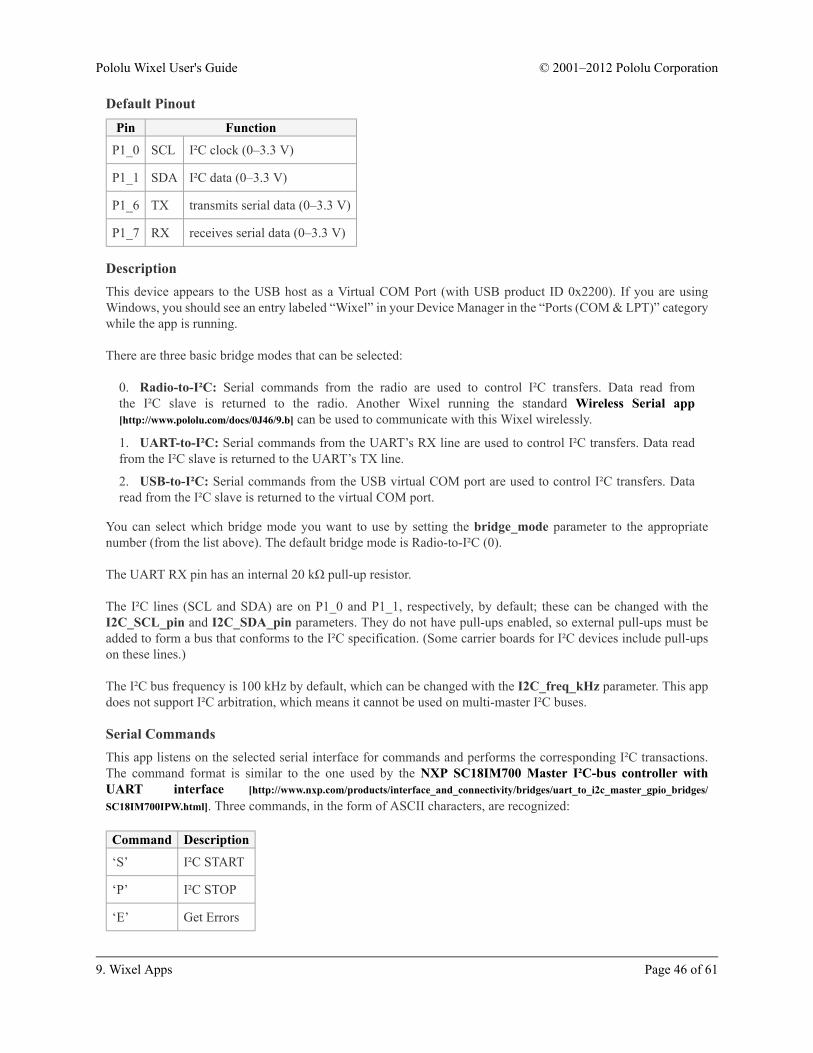
Default PinoutPin Function
P1_0 SCL I²C clock (0–3.3 V)
P1_1 SDA I²C data (0–3.3 V)
P1_6 TX transmits serial data (0–3.3 V)
P1_7 RX receives serial data (0–3.3 V)
DescriptionThis device appears to the USB host as a Virtual COM Port (with USB product ID 0x2200). If you are usingWindows, you should see an entry labeled “Wixel” in your Device Manager in the “Ports (COM & LPT)” categorywhile the app is running.
There are three basic bridge modes that can be selected:
0. Radio-to-I²C: Serial commands from the radio are used to control I²C transfers. Data read fromthe I²C slave is returned to the radio. Another Wixel running the standard Wireless Serial app[http://www.pololu.com/docs/0J46/9.b] can be used to communicate with this Wixel wirelessly.
1. UART-to-I²C: Serial commands from the UART’s RX line are used to control I²C transfers. Data readfrom the I²C slave is returned to the UART’s TX line.
2. USB-to-I²C: Serial commands from the USB virtual COM port are used to control I²C transfers. Dataread from the I²C slave is returned to the virtual COM port.
You can select which bridge mode you want to use by setting the bridge_mode parameter to the appropriatenumber (from the list above). The default bridge mode is Radio-to-I²C (0).
The UART RX pin has an internal 20 kΩ pull-up resistor.
The I²C lines (SCL and SDA) are on P1_0 and P1_1, respectively, by default; these can be changed with theI2C_SCL_pin and I2C_SDA_pin parameters. They do not have pull-ups enabled, so external pull-ups must beadded to form a bus that conforms to the I²C specification. (Some carrier boards for I²C devices include pull-upson these lines.)
The I²C bus frequency is 100 kHz by default, which can be changed with the I2C_freq_kHz parameter. This appdoes not support I²C arbitration, which means it cannot be used on multi-master I²C buses.
Serial CommandsThis app listens on the selected serial interface for commands and performs the corresponding I²C transactions.The command format is similar to the one used by the NXP SC18IM700 Master I²C-bus controller withUART interface [http://www.nxp.com/products/interface_and_connectivity/bridges/uart_to_i2c_master_gpio_bridges/SC18IM700IPW.html]. Three commands, in the form of ASCII characters, are recognized:
Command Description
‘S’ I²C START
‘P’ I²C STOP
‘E’ Get Errors
Pololu Wixel User's Guide © 2001–2012 Pololu Corporation
9. Wixel Apps Page 46 of 61

The general format for a command sequence begins with a START command (‘S’), followed by a slave deviceaddress, the number of data bytes to be written or read, the data to be written (if a write is being done), andfinally a STOP command (‘P’). If a read is being done, the data read from the slave device will be returned on theserial interface. The least significant bit of the slave device address (the data direction bit) indicates whether theoperation is a write (0) or a read (1). A repeated START condition can be generated by issuing another STARTcommand without sending a STOP command.
For example, to write the value 0x2E to register 0xF4 on a slave device with the write address 0xEE, the followingsequence of bytes could be sent to the Wixel:
‘S’, 0xEE, 2, 0xF4, 0x2E, ‘P’
To read a two-byte value from register 0xF6 on the same device, whose read address would be 0xEF, the followingsequence could be issued (the second ‘S’ generates a repeated START):
‘S’, 0xEE, 1, 0xF6, ‘S’, 0xEF, 2, ‘P’
The Wixel would respond with the two data bytes read from the slave.
Any invalid or unrecognized command is ignored and causes the Invalid Command error bit to be set.
To prevent an unfinished command sequence from leaving the I²C bus in an unusual state, this app will timeout and reset the bus if a byte is not received on the serial interface within 500 ms of the last byte. After thishappens, the Command Timeout error bit will be set, and a new command sequence must be initiated with aSTART command. The command timeout delay can be changed with the cmd_timeout_ms parameter; a value of0 disables this timeout.
If the Wixel receives a Get Errors command (‘E’), it will respond with a single byte containing the status of severalerror conditions. This command can be issued any time the app is not expecting a slave address or data byte.
When an error occurs, the corresponding bit in the error byte is set and remains set until the errors are read withthe Get Errors command, after which it is cleared internally. The following table shows the error condition thatcorresponds to each bit:
Pololu Wixel User's Guide © 2001–2012 Pololu Corporation
9. Wixel Apps Page 47 of 61
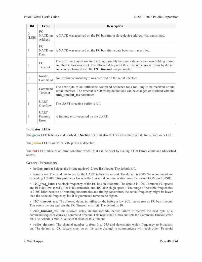
Bit Error Description
0(LSB)
I²CNACK onAddress
A NACK was received on the I²C bus after a slave device address was transmitted.
1I²CNACK onData
A NACK was received on the I²C bus after a data byte was transmitted.
2 I²CTimeout
The SCL line stayed low for too long (possibly because a slave device was holding it low)and the I²C bus was reset. The allowed delay until this timeout occurs is 10 ms by defaultand can be changed with the I2C_timeout_ms parameter.
3 InvalidCommand An invalid command byte was received on the serial interface.
4 CommandTimeout
The next byte of an unfinished command sequence took too long to be received on theserial interface. The timeout is 500 ms by default and can be changed or disabled with thecmd_timeout_ms parameter.
5 UARTOverflow The UART’s receive buffer is full.
6UARTFramingError
A framing error occurred on the UART.
Indicator LEDsThe green LED behaves as described in Section 1.a, and also flickers when there is data transferred over USB.
The yellow LED is on when VIN power is detected.
The red LED indicates an error condition when lit; it can be reset by issuing a Get Errors command (describedabove).
General Parameters• bridge_mode: Selects the bridge mode (0–2, see list above). The default is 0.
• baud_rate: The baud rate to use for the UART, in bits per second. The default is 9600. We recommend notexceeding 115200. This parameter has no effect on serial communication over the virtual COM port (USB).
• I2C_freq_kHz: The clock frequency of the I²C bus, in kilohertz. The default is 100. Common I²C speedsare 10 kHz (low speed), 100 kHz (standard), and 400 kHz (high speed). The range of possible frequenciesis 2-500 kHz; because of rounding inaccuracies and timing constraints, the actual frequency might be lowerthan the selected frequency, but it is guaranteed never to be higher.
• I2C_timeout_ms: The allowed delay, in milliseconds, before a low SCL line causes an I²C bus timeout.This resets the bus and sets the I²C Timeout error bit. The default is 10.
• cmd_timeout_ms: The allowed delay, in milliseconds, before failure to receive the next byte of acommand sequence causes a command timeout. This resets the I²C bus and sets the Command Timeout errorbit. The default is 500. A value of 0 disables this timeout.
• radio_channel: The channel number is from 0 to 255 and determines which frequency to broadcaston. The default is 128. Wixels must be on the same channel to communicate with each other. To avoid
Pololu Wixel User's Guide © 2001–2012 Pololu Corporation
9. Wixel Apps Page 48 of 61
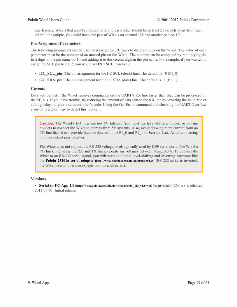
interference, Wixels that aren’t supposed to talk to each other should be at least 2 channels away from eachother. For example, you could have one pair of Wixels on channel 128 and another pair on 130.
Pin Assignment ParametersThe following parameters can be used to reassign the I²C lines to different pins on the Wixel. The value of eachparameter must be the number of an unused pin on the Wixel. The number can be computed by multiplying thefirst digit in the pin name by 10 and adding it to the second digit in the pin name. For example, if you wanted toassign the SCL pin to P1_2, you would set I2C_SCL_pin to 12.
• I2C_SCL_pin: The pin assignment for the I²C SCL (clock) line. The default is 10 (P1_0).
• I2C_SDA_pin: The pin assignment for the I²C SDA (data) line. The default is 11 (P1_1).
CaveatsData will be lost if the Wixel receives commands on the UART’s RX line faster than they can be processed onthe I²C bus. If you have trouble, try reducing the amount of data sent to the RX line by lowering the baud rate oradding delays to your microcontroller’s code. Using the Get Errors command and checking the UART Overflowerror bit is a good way to detect this problem.
Caution: The Wixel’s I/O lines are not 5V tolerant. You must use level-shifters, diodes, or voltagedividers to connect the Wixel to outputs from 5V systems. Also, avoid drawing more current from anI/O line than it can provide (see the discussion of P1_0 and P1_1 in Section 1.a). Avoid connectingmultiple output pins together.
The Wixel does not support the RS-232 voltage levels typically used by DB9 serial ports. The Wixel’sI/O lines, including the RX and TX lines, operate on voltages between 0 and 3.3 V. To connect theWixel to an RS-232 serial signal, you will need additional level-shifting and inverting hardware likethe Pololu 23201a serial adapter [http://www.pololu.com/catalog/product/126] (RS-232 serial is inverted;the Wixel’s serial interface expects non-inverted serial).
Versions• Serial-to-I²C App 1.0 [http://www.pololu.com/file/download/serial_i2c_v1.0.wxl?file_id=0J480] (26k wxl), released2011-05-03: Initial release.
Pololu Wixel User's Guide © 2001–2012 Pololu Corporation
9. Wixel Apps Page 49 of 61

10. Writing Your Own Wixel App10.a. Getting Started in WindowsTo get started developing your own Wixel Apps using Windows as the development platform, we recommendthat you download and install the Pololu Wixel Development Bundle: wixel-dev-bundle-120127.exe[http://www.pololu.com/file/download/wixel-dev-bundle-120127.exe?file_id=0J526] (10MB exe). This bundle contains fourthings:
• Wixel SDK [http://pololu.github.com/wixel-sdk/]: Contains source code (for libraries and applications) that willhelp you develop your own applications for the Wixel.
• SDCC – Small Device C Compiler [http://sdcc.sourceforge.net/]: A free compiler that is used to compile thecode in the Wixel SDK.
• Pololu GNU Build Utilities: Windows versions of some open-source utilities that are required by the SDK.
• Notepad++ [http://notepad-plus-plus.org/]: A free text editor which is convenient to use when editing Wixelcode.
10.b. Compiling an Example AppAfter you have installed all the necessary software (either from the Wixel Development Bundle or from othersources), you should try compiling an example app and loading it onto a Wixel to make sure that your system isset up correctly.
Compiling AppsGo to the folder where you installed the Wixel SDK (C:\wixel-sdk is the default) and run make_all.bat. Ifeverything is installed correctly, the output of that batch file should look something like this:
You have now built all the apps in the Wixel SDK and all the libraries that they depend on. Every subfolder of theapps folder should now have a WXL file in it. This is a compiled app which can be loaded onto Wixels using theWixel Configuration Utility or the Wixel Command-Line Utility (WixelCmd).
Pololu Wixel User's Guide © 2001–2012 Pololu Corporation
10. Writing Your Own Wixel App Page 50 of 61

You might get the following error message from make in Windows:
make: Interrupt/Exception caught (code = 0xc00000fd, addr = 0x425073)
If you get this error, please run “make -v” at a Command Prompt and make sure that you arerunning GNU Make 3.82-pololu2 [https://github.com/pololu/make]. This version of make is includedin the latest Wixel Development Bundle (see Section 10.a). If the output from “make -v” showssome other version of make even after installing the Wixel Development Bundle, then you shouldremove that other version of make from your PATH or reorder your PATH so that version3.82-pololu2 is used. You can edit your PATH environment variable from the Control Panel. Seethe pololu/make wiki on GitHub [https://github.com/pololu/make/wiki] for more information on thisproblem.
Loading an App onto Wixels from the Command LineWhile you are developing an app, it can be useful to have a way to load an app onto the target Wixel fromthe command line. You can do this with the Makefile: plug a Wixel into your computer, open up a commandprompt, navigate to the wixel-sdk folder, and type make load_example_blink_led. This should compile theexample_blink_led app (if it is out of date) and then invoke the Wixel Command-Line Utility (WixelCmd) inorder to load the app onto all Wixels connected to your computer. The output should look something like this:
The example blink LED application should be running now. The Wixel’s yellow LED should be off, and the redLED should be blinking. If that is the case, then congratulations! You have successfully compiled a program andloaded it onto the Wixel.
You can also specify settings at the command line. Try running this command:
make load_example_blink_led S="blink_period_ms=100"
You should now see the LED blinking 5 times faster than it was before. To specify multiple settings, put othersettings inside the quotes and separate all settings with spaces.
Opening an App with the Wixel Configuration UtilityYou can also open the app in the Wixel Configuration Utility if you want to. Try running this command:
make open_example_blink_led
The Wixel Configuration Utility should start running and open the example_blink_led app.
Pololu Wixel User's Guide © 2001–2012 Pololu Corporation
10. Writing Your Own Wixel App Page 51 of 61

Using Eclipse with the Wixel SDK to developWixel applications.
Creating Your Own AppsNow that you know how to compile apps and quickly load them onto the Wixel to test them, you are ready todevelop your own Wixel apps. You can either modify one of the existing apps in the SDK or create your own app.To create your own app, simply copy one of the existing app folders and change the name. You do not need tomodify the Makefile when you create a new app; the Makefile will automatically detect the app as long as it is inthe apps folder. When you are developing your app, you can use all of the commands above except you shouldreplace “example_blink_led” with the name of your app (the name of the subfolder in the apps folder). For moreinformation, including documentation of all the libraries in the Wixel SDK, see the Wixel SDK Documentation[http://pololu.github.com/wixel-sdk/].
10.c. Using the Eclipse IDEYou can develop Wixel applications using any texteditor. If you use the free, open source Eclipse IDE,you can benefit from some of its advanced C/C++editing features. The following is a tutorial on how toset up Eclipse for use with the Wixel SDK.
1. Install the Wixel SDK on your computer andcompile an example app by following theinstructions in the previous sections.
2. Download and install the Eclipse IDE forC/C++ Developers [http://www.eclipse.org/downloads/].If you are a Windows user, we recommend that youdownload the 32-bit version of Eclipse, even if youhave a 64-bit operating system. You may need toinstall a Java Runtime Environment (JRE) beforeyou can run Eclipse.
3. Run Eclipse. It will ask you to choose a workspace folder. Eclipse does not allow the workspaceand project folders to be the same. Therefore, we recommend making a new folder called something likeeclipse_workspace, moving the wixel-sdk folder inside of it, and choosing that new folder to be yourEclipse workspace location. By doing this, you can avoid having a large number of files in your workspace.You can switch your workspace location later if you need to.
4. After choosing your workspace folder, you will see a welcome screen that says “Welcome to the EclipseIDE for C/C++ Developers” and has several circular icons on it. Click the icon with the yellow arrow in it togo to the Workbench.
5. From the File Menu, select New > C Project. This will open up a dialog entitled “C Project”.
6. For the Project name, enter wixel-sdk. The Location box should now show the correct location of yourwixel-sdk folder. Eclipse will show a warning at the top of the window that says “Directory with specifiedname already exists.” (this is good).
7. Under Project type, select Makefile project > Empty Project. It does not matter what toolchain youselect.
8. Click the Finish button to finish creating the wixel-sdk project.
9. Press Ctrl+B or select Project > Build All to build the project. This is equivalent to running make all
in the wixel-sdk folder. You can see the build output by selecting the Console tab at the bottom or by goingto Window > Show View > Console.
Pololu Wixel User's Guide © 2001–2012 Pololu Corporation
10. Writing Your Own Wixel App Page 52 of 61

10. In the left-hand pane, you will see the “C/C++ Projects” or “Project Explorer” view. This view shoulddisplay one entry entitled wixel-sdk which represents the project you just created. Double click on theproject name to expand it and see all the folders and files inside it.
11. Navigate to the apps/example_blink_led folder and double-click on example_blink_led.c. This willopen the file in the center pane.
12. Make a small change to example_blink_led.c, such as removing a blank line or adding a comment.Save the file by pressing Ctrl+S or by selecting File > Save.
13. Press Ctrl+B or select Project > Build All to rebuild the project. When you do this, Eclipse runs makein the wixel-sdk folder, which builds all of the apps and the libraries they depend on. Once again, you cansee the build output by selecting the Console tab at the bottom or by going to Window > Show View >Console. The Wixel SDK’s Makefile should detect that example_blink_led.c has changed, so it shouldrebuild the app. The output in the Console view should look something like this:
14. Congratulations! You have made your first change to an app and recompiled it using the Eclipse IDE.
15. When you are ready to load the app onto a Wixel, open up a Command Prompt, navigate to the wixel-
sdk directory, and run make load_APPNAME where APPNAME is the name of the app. We do not have a wayof loading apps onto the Wixel that is integrated into Eclipse.
Improving the configuration of Eclipse1. In the Project menu, select Properties. Under C/C++ General > Paths and Symbols > Includes, clickthe Add… button. Enter the full path to SDCC’s include directory. If you are on a 64-bit machine and SDCCis installed in the default location, this will be “C:\Program Files (x86)\SDCC\include”. Check the “Add toall languages” box and click OK. This will allow Eclipse to find the headers provided by the compiler, suchas stdio.h, which will reduce the number of warnings you see from Eclipse while developing apps.
2. In the Window menu, select Preferences. Under C/C++ > Code Analysis, uncheck the boxes for “Typecannot be resolved” and “Field cannot be resolved”. We found that these two errors were not workingcorrectly under Eclipse Indigo Service Release 1, and they will be caught by the compiler regardless of howyou configure Eclipse.
3. In the Window menu, select Preferences. Under General > Workspace, check Save automaticallybefore build. This makes Eclipse save your code automatically before building, so you do not have toremember to do that.
Advanced Features of EclipseThe attraction of using Eclipse is the large number of advanced C/C++ editing features it provides. Here are justa few of these features:
• Eclipse supports C syntax highlighting.
Pololu Wixel User's Guide © 2001–2012 Pololu Corporation
10. Writing Your Own Wixel App Page 53 of 61
• If an error occurs during the build, you can double-click on the error from the Console or Problems viewin order to jump directly to the line of code that has the problem.
• If you put your text cursor on a function name, variable name, preprocessor macro, or include directive,then you can quickly jump to the place where that item is defined by pressing F3 or by right-clicking andselecting Open Declaration.
• Pressing Ctrl+Tab inside a source (.c) file opens up the corresponding header (.h) file, and vice-versa.This is especially useful if you are writing a Wixel library.
• The Outline view shows all the variables and functions defined in the current file. You can click on one ofthem to quickly jump to its definition. You can even drag them within the Outline view to change their orderin your file.
• If you put your cursor on a function name, you can see all the places where that function is called bytyping Ctrl+Alt+H or right-clicking and selecting Open Call Heirarchy.
• Eclipse makes it easy to rename selected objects (variables, methods/functions, etc.) by automaticallypropagating the changes to other files in the project. You can access this feature by putting your cursor on aname and then right-clicking and selecting Refactor > Rename…
• Eclipse scans your files for comments containing “TODO”. These comments are aggregated in the Tasksview, and you can also easily find them in your current file by clicking on the little blue rectangles to theright of the vertical scroll bar. Each blue rectangle represents the location of a TODO item in your file.
Pololu Wixel User's Guide © 2001–2012 Pololu Corporation
10. Writing Your Own Wixel App Page 54 of 61
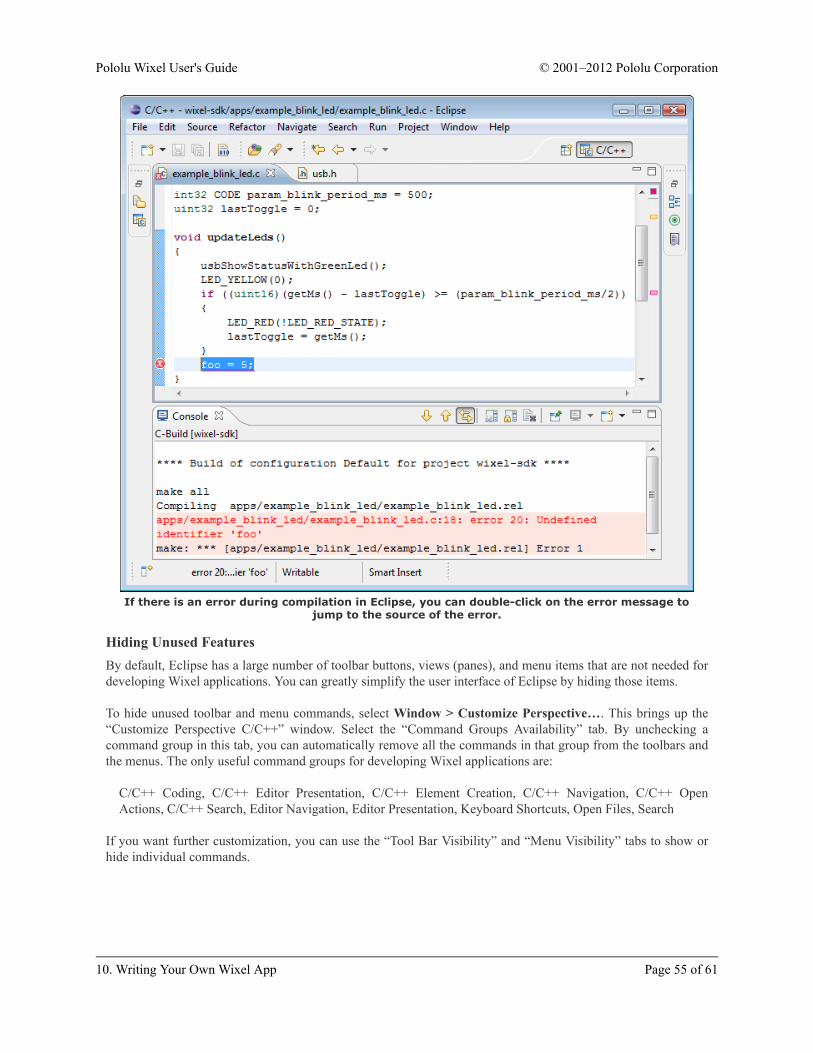
If there is an error during compilation in Eclipse, you can double-click on the error message tojump to the source of the error.
Hiding Unused FeaturesBy default, Eclipse has a large number of toolbar buttons, views (panes), and menu items that are not needed fordeveloping Wixel applications. You can greatly simplify the user interface of Eclipse by hiding those items.
To hide unused toolbar and menu commands, select Window > Customize Perspective…. This brings up the“Customize Perspective C/C++” window. Select the “Command Groups Availability” tab. By unchecking acommand group in this tab, you can automatically remove all the commands in that group from the toolbars andthe menus. The only useful command groups for developing Wixel applications are:
C/C++ Coding, C/C++ Editor Presentation, C/C++ Element Creation, C/C++ Navigation, C/C++ OpenActions, C/C++ Search, Editor Navigation, Editor Presentation, Keyboard Shortcuts, Open Files, Search
If you want further customization, you can use the “Tool Bar Visibility” and “Menu Visibility” tabs to show orhide individual commands.
Pololu Wixel User's Guide © 2001–2012 Pololu Corporation
10. Writing Your Own Wixel App Page 55 of 61

10.d. Sharing Your App with the Wixel CommunityPreparing your app for the communityPlease make sure that you have set up the following sections in your WXL file:
• description – this should fully describe what your app does or link to a web site with a completedescription. Since other people will be trying this on their Wixels, make sure to bring our attention toanything that may cause damage or incompatibility. Most importantly, any IO ports used as outputs shouldbe explicitly listed in the description.
• license – this specifies the terms under which others may distribute copies or modifications of your app.We recommend and use the MIT license, which is simple and allows widespread use of your code. Note thatif you have used the Wixel SDK to build your app, you need to include our license, though you may add yourown restrictions if necessary. We recommend using the following template, which will make it easy for us toshare your app or to include it in the Wixel SDK:
Copyright (c) 2011 <YOUR NAME>. Documentation for this app is available at:
http://<YOUR SITE>/
Copyright (c) 2011 Pololu Corporation. For more information, see
http://www.pololu.com/http://forum.pololu.com/
Permission is hereby granted, free of charge, to any personobtaining a copy of this software and associated documentationfiles (the "Software"), to deal in the Software withoutrestriction, including without limitation the rights to use,copy, modify, merge, publish, distribute, sublicense, and/or sellcopies of the Software, and to permit persons to whom theSoftware is furnished to do so, subject to the followingconditions:
The above copyright notice and this permission notice shall beincluded in all copies or substantial portions of the Software.
THE SOFTWARE IS PROVIDED "AS IS", WITHOUT WARRANTY OF ANY KIND,EXPRESS OR IMPLIED, INCLUDING BUT NOT LIMITED TO THE WARRANTIESOF MERCHANTABILITY, FITNESS FOR A PARTICULAR PURPOSE ANDNONINFRINGEMENT. IN NO EVENT SHALL THE AUTHORS OR COPYRIGHTHOLDERS BE LIABLE FOR ANY CLAIM, DAMAGES OR OTHER LIABILITY,WHETHER IN AN ACTION OF CONTRACT, TORT OR OTHERWISE, ARISINGFROM, OUT OF OR IN CONNECTION WITH THE SOFTWARE OR THE USE OROTHER DEALINGS IN THE SOFTWARE.
Announcing your app on the Wixel forumWhen you are ready for the community to try out a version of your app, you may announce it on the Wixelforum [http://forum.pololu.com/viewforum.php?f=30], attaching your WXL file. It is helpful to paste a copy of yourdescription into your post so that we can see what your app is about before downloading it.
Contributing your source codeSharing your source code greatly increases the value of your app, since other members of the community will beable to adapt it to their own projects or learn from your code. You might also have made changes to the commonsections of the Wixel SDK that you would like us to incorporate, or you might have discovered and want toshare your fixes. For all of these reasons, we are maintaining the Pololu Wixel SDK Repository on GitHub[http://github.com/pololu/wixel-sdk] as a central location for sharing Wixel code. You can easily use this site to forkyour own version of the Wixel SDK, show us what you are working on, submit changes, and so on.
Pololu Wixel User's Guide © 2001–2012 Pololu Corporation
10. Writing Your Own Wixel App Page 56 of 61

GitHub uses the Git Version Control System [http://git-scm.com/] for tracking versions and branchesof code, so we highly recommend learning how to use Git if you want to share your code with theWixel community or even just to get the latest version for your own use. Teaching Git is beyond thescope of this User’s Guide, but there are many good tutorials available on the web. For example,the Git tutorial [http://help.github.com/set-up-git-redirect] provided by GitHub will help you get started.
For the rest of this section, we will assume that you are comfortable with Git.
If you have been following the instructions in this document, your code is located within the wixel-sdk folderalong with the rest of the Wixel SDK. This folder is actually a clone of our Git repository, which means that itincludes history and version information as well as a link back to our repository (a remote), within the folder .git.As long as you have not modified the contents of .git, you should be able to use Git to commit your changes,pull updates from us, and push your changes to a public repository. To make sure that Git is working correctly, trytyping the following command at the command prompt from within the wixel-sdk folder:
git log
This should display a list of recent commits in the repository. Alternatively, you can use the program gitk or youcan use the “Show Log” command of TortoiseGit to view a much more detailed, graphical representation of thelog. After reviewing the log, you can add and commit all of your new files:
git add <list of new files...>git commit -a
Alternatively, you can use the “Commit…” command of TortoiseGit. Either way, you will be shown a list ofnew or modified files and prompted for a commit message. Please check this over carefully and write a gooddescription of your changes, because it is very hard to change your commits after you make them public.
In some cases, you might want to start over with a fresh copy of the Wixel SDK, which you can make by typing
git clone -o pololu git://github.com/pololu/wixel-sdk.git
into a command prompt. At any time, you can download the latest updates from us and merge them into your codeby typing the following command:
git pull pololu
Initially, you will commit your changes to your local repository, but when you are ready to publish them, youshould set up your own repository on GitHub to make them accessible to the community. To do this, sign up fora GitHub account and fork our repository into a repository on your account. Please do this by clicking the “fork”button at the top of our repository [http://github.com/pololu/wixel-sdk] so that it will be connected within the GitHubsystem – this way we will see your changes and can easily incorporate them into the SDK. After making yourfork, you can push all of the changes from your local repository to GitHub with
git remote add myrepo <GitHub URL>git push myrepo
where <GitHub URL> is the SSH or HTTP URL shown on your GitHub page.
Pololu Wixel User's Guide © 2001–2012 Pololu Corporation
10. Writing Your Own Wixel App Page 57 of 61

Finally, you will probably want to post a link to your GitHub repository on the Wixel forum[http://forum.pololu.com/viewforum.php?f=30]. This will help others find out about it and give you feedback on yourcontribution.
10.e. USB Configurations Recognized by the Wixel Configuration SoftwareThe Wixel Configuration Utility and the Wixel Command-Line Utility can currently only recognize certain Wixelapps. If your app is not recognized, then users of your app will not easily be able to reconfigure it after they haveloaded it onto their Wixel (they will have to get their Wixel into bootloader mode manually).
To be recognized, your app must implement a particular USB interface. Specifically, it must implement a USBCDC ACM virtual COM port with vendor ID 0x1FFB and product ID 0x2200. When the USB host sends acommand to your app that sets the baud rate to 333, your app should enter bootloader mode. Your app shouldwork with the wixel_serial.inf driver which is installed along with the other Windows software (see Section3.a). The easiest way to write an app that meets these requirements is to use the usb_cdc_acm.lib library in theWixel SDK.
In the future we will add support for other types of USB interfaces if there is a need for it. Please contact us[http://www.pololu.com/contact] if you would like to use other types of interfaces in your apps.
10.f. Wixel App File FormatFor the purpose of loading a compiled program onto a Wixel, the Wixel Configuration Utility and the WixelCommand-Line Utility (WixelCmd) accept two file formats: Intel HEX (.hex) and Wixel App (.wxl). The IntelHEX (.hex) file format is an industry standard, and can be produced by most toolchains. The Wixel App(.wxl) file format is a simple format created by Pololu that includes an Intel HEX file inside it along withimportant metadata, such as the names and addresses of user-configurable parameters. The Wixel App file formatis designed to be extensible and easy to generate.
The Wixel App file is plain text: every byte is an ASCII-encoded character. The allowed ASCII codes are 0x20through 0x7F and also 0x09 (tab), 0xA (new line, “\n”), and 0xD (carriage return, “\r”). The bytes in a Wixel Appfile are divided into lines. Line endings can be encoded with any of the following byte sequences: “\r\n” (0xD,0xA), “\r” (0xD), or “\n” (0xA).
The first line must be “Pololu Wixel Application - www.pololu.com”. This line explains the purpose of the WixelApp file. The second line must be “1.0”. This specifies the version number of the file format used in the file.
The third line and all the lines below it are divided into sections. Each section has a one-line header at the top ofit that specifies the name of the section. The header line consists of 6 equals signs (======) followed by a space,followed by the name of the section. The order of the sections does not matter. The only sections required by theWixel software are the cdb and hex sections.
The hex sectionThe hex section contains an Intel Hex file that specifies the bytes to write to the flash of the Wixel. See the IntelHEX [http://en.wikipedia.org/wiki/Intel_HEX] page on Wikipedia for more information. The flash memory region onthe CC2511F32 that is available for Wixel applications consists of addresses 0x400 through 0x77FF (inclusive).Any line of the HEX file that writes to bytes outside of this region will be ignored.
The license sectionThe license section is a human-readable section that should specify the terms under which others may distributecopies or modifications of the app. The Wixel SDK automatically inserts the MIT license into all Wixel App filesbecause that is required by the Wixel SDK’s license.
Pololu Wixel User's Guide © 2001–2012 Pololu Corporation
10. Writing Your Own Wixel App Page 58 of 61

The description sectionThe description section is a human-readable section that should describe what the app does or link to a web siteabout the app.
The cdb sectionThe cdb section contains the names and addresses of the user-configurable parameters. For each parameter, theremust be two lines in this section (not necessarily consecutive) as specified below.
One line contains the address of the parameter, and must be of the form: L:G$param_NAME$0$0:ADDRESS whereNAME is the name of the parameter and ADDRESS specifies the address of the parameter in the Wixel’s flashmemory as a 4-digit hexadecimal number (e.g. “11C3”).
Another line contains the type of the parameter, and must be of the form: S:G$param_NAME$0$0(TYPE),D,0,0where NAME is the name of the parameter and TYPE is the type of the parameter. Currently, the only allowedtype is a 32-bit signed integer, which is encoded as “{4}SL:S”.
The Wixel SDK generates the cdb of section by running grep on the CDB file produced by SDCC during thelinking step, selecting all lines containing the string “param”. This means you can define a parameter simply bywriting the following code in your Wixel App, outside of any function:
int32 CODE param_NAME = DEFAULT_VALUE;
where NAME is the name of your parameter and DEFAULT_VALUE is the default value it will have if the userdoes not change its value. This default value is stored in the hex section, not the cdb section.
You could put your entire CDB file in the WXL file if you wanted to; the software ignores unrecognized lines.However the CDB file can be hundreds of kilobytes long so this is not encouraged.
Wixel App files usually have non-Windows line endings in the cdb section so they can not beviewed properly in Notepad or other text editors that only recognize Windows line endings.
Pololu Wixel User's Guide © 2001–2012 Pololu Corporation
10. Writing Your Own Wixel App Page 59 of 61

11. The Wixel USB BootloaderThe Wixel comes with a USB bootloader that can be used in conjunction with the Wixel Configuration Utilityor WixelCmd to upload apps to the Wixel (no external programmer is required). This section documents sometechnical details of the bootloader and is intended for advanced users.
Flash Memory SectionsThe bootloader occupies the first 1 KiB (1024 bytes) and the last 2 KiB of the CC2511F32’s flash memory. Thosesections of memory are protected to prevent accidental corruption of the bootloader. The remaining 29 KiB offlash, known as the application section, is available for the app. The bootloader places no restrictions on what datacan be written to the application section. However, the bootloader will consider the application to be invalid andnot allow any code in the application section to run if the first byte of the application section (address 0x400) is0xFF, which should never be the case for an application that is compiled correctly.
The CC2511’s standard entry vector and the interrupt vectors are remapped by the bootloader to the beginning ofthe application section. The application’s entry vector should be placed at 0x400. The first interrupt vector shouldbe at 0x403 and consecutive interrupt vectors should be 8 bytes apart.
The application can put the Wixel into bootloader mode by jumping to address 0x6 using an ljmp instruction.
The block of flash memory from 0x3CC to 0x3FF in the bootloader is used to store some information that can beread by the application:
• Addresses 0x3CC–0x3DD contain the USB device descriptor of the bootloader, as defined in the USB 2.0Specification.
• Addresses 0x3E0–0x3E3 contain the serial number of the Wixel as a 32-bit unsigned little-endian integer.
• Addresses 0x3E6–0x3FD contain the serial number of the Wixel in USB string descriptor format.
The bytes in the 0x3CC–0x3FF region not mentioned above are reserved and contain only zeros.
Pololu Wixel User's Guide © 2001–2012 Pololu Corporation
11. The Wixel USB Bootloader Page 60 of 61

When the Wixel resets, it uses this procedure to decidewhether to run the bootloader or the app.
Startup ProcedureEvery time the Wixel powers on, thebootloader’s startup code runs. This codedecides whether to launch the bootloaderor the application by using the followingprocedure: First, it configures the threeLED lines to have internal pull-downresistors and disables the internal pull-upand pull-down resistors of the other Port2 pins. Second, if the application is notvalid (first byte is 0xFF), it goes intobootloader mode. Third, if the Wixel hasUSB power and the yellow LED (P2_2)line is high, it goes into bootloader mode.Finally, is none of these tests have causedit to go into bootloader mode, it runs theapplication.
Pololu Wixel User's Guide © 2001–2012 Pololu Corporation
11. The Wixel USB Bootloader Page 61 of 61