wizord user 1.6 · • the energizer is fully compliant to iec 60335-2-76. • there are no user...
TRANSCRIPT
WIZORD Electric Fence Energizer
User Manual
Introduction 3
Company Profile 3
Guarantee 4
Nemtek group outlets 5
Standard Operating Procedures 6
Standard Operating Procedures - Notes 7
Standard Operating Procedures - LEDs 8
Features & Functions 9
IEC Safety Information 10
Document revision history 10
Table of Contents
2

INTRODUCTION
Thank you for choosing our product! NEMTEK Electric Fence Energizers are designed and
manufactured to provide many years of reliable use, if installed and maintained correctly.
The guidelines provided in this manual will assist you with the basic operation and maintenance
of your WIZORD.
The WIZORD is designed and manufactured in South Africa for the South African and
international markets. More information on our products and general information is available
on our web site at: http://www.nemtek.com.
COMPANY PROFILE
The NEMTEK Group of Companies manufacture and distribute intelligent electronic security and
perimeter control systems and have been involved in the security industry since 1990.
We have our own research and development team, designing and manufacturing a full range of
globally competitive electric fence energizers and related products.
NEMTEK is continually updating its products according to South African and international
standards in order to ensure the highest quality products and continuous customer satisfaction.
3
Introduction & Company Profile

GUARANTEE
The WIZORD energizer, manufactured by IO Tech Manufacturing (Pty) Ltd, is guaranteed for a
period of two year from date of sale against defects due to faulty workmanship or materials.
IO Tech Manufacturing (Pty) Ltd will, at its discretion, either repair or replace a product that
proves to be defective.
IO Tech Manufacturing (Pty) Ltd guarantees that the product, when properly installed and used
in line with the specification as determined by Nemtek from time to time, will execute its
function of generating a suitable potential. Nemtek does not guarantee that the operation of
the product will be uninterrupted and totally error free. Faulty units must be returned to one of
the Nemtek Group outlets. The buyer shall pay all shipping and other charges for the return of
the product to Nemtek or Nemtek Security Warehouse.
LIMITATION OF GUARANTEE
The guarantee does NOT apply to defects resulting from acts of God, modifications made by
the buyer or any third party, misuse, neglect, abuse, accident and mishandling.
EXCLUSIVE REMEDIES
The remedies provided herein are Nemtek’s sole liability and the buyer’s sole and exclusive
remedies for breach of guarantee. Nemtek shall not be liable for any special, incidental,
consequential, direct or indirect damages, whether based on contact, tort, or any other legal
theory. The foregoing guarantee is in lieu of any and all other guarantees, whether expressed,
implied, or statutory, including but not limited to warranties of merchantability and suitability
for a particular purpose.
Guarantee
4

HEAD OFFICE
Tel: +27 (0)11 462 8283 Northriding Commercial Park
Fax: +27 (0)11 462 7132 Stand 251, Aintree Street, Northriding
Randburg, South Africa
EXPORTS
Tel: +27 (0)11 462 8283 [email protected]
Fax: +27 (0)11 462 7132
EDENVALE
Tel: +27 (0)11 453 1970 Unit 4, Meadowdale Park
Fax: +27 (0)11 453 1858 Cnr. Dick Kemp & Herman Roads
Meadowdale, Edenvale, South Africa
CAPE TOWN
Tel: +27 (0)21 386-3742 27B Concord Crescent, Airport City
Fax: +27 (0)21 386-5573 Cape Town, South Africa
NELSPRUIT
Tel: +27 (0)13 752-2187 Waterval Ave, Riverside Industrial
Fax: +27 (0)13 752-2188 Nelspruit, South Africa
KWAZULU-NATAL
Tel: +27 (0)31 701-2125 19 Henwood Road
Fax: +27 (0)31 701-2125 Pinetown, South Africa
AUSTRALIA
Tel: (08) 9303 9855 Unit 5, 19 Innovation Circuit,
Email: [email protected] Wangara, 6065, Perth, WA, Australia
Website: www.nemtek.com
E-mail: [email protected]
Manufactured in South Africa
5
NEMTEK Group Outlets

6
TURNING YOUR UNIT ON / OFF:
In the default state, the energizer can be turned on or off by holding the plastic tab
over the corresponding logo on the fascia of the unit. The unit will beep once when
turned on and twice when turned off.
FENCE STATUS INDICATION:
The unit will indicate that a condition is currently active (fence fault, gate open, or
service condition) if the corresponding LED is flashing; e.g. if the fence LED is
flashing, the fence voltage is currently not satisfactory. If the fence alarm indication
LED is lit continuously, there was a fence alarm condition previously but the fence
voltage is now satisfactory. Similarly, if the gate alarm indication LED is lit
permanently, the gate opening time exceeded the entry delay period but is now
closed. If the gate indication LED is flashing, the gate is still open.
If the mains supply is present the power LED is lit and it will go out with a mains
failure. The On LED will be lit when the unit is switched on and it will be off when it
is switched off. The On LED will flash when the unit is switched to the Low Voltage
Mode.
ALARM INDICATION:
The fence and gate inputs are configured to trigger external alarms and the internal
buzzer. The service condition will activate the buzzer only. Be aware that, should
there be a prolonged power failure, the battery may run low and cause the service
light to flash. If the mains interruption is sufficiently long, the unit will shut down
and there will be no indication of mains failure.
RESETTING THE ALARM:
Switch the unit off with the Nemtek tab or remote key-switch. This will silence the
siren (if it has not already timed-out), internal buzzer and will switch the strobe off.
One of the alarm lights will be flashing or will remain lit to indicate the source of
the alarm. A permanently lit indicator notifies the user that the fault no longer
exists. In the latter case simply turning the energizer On again will clear the
memory condition. A flashing alarm light illustrates that the fault condition persists.
In this case rectify the condition which caused the alarm. To reset and clear the
memory condition turn the energizer On and Off and On again. Only if the alarm
condition is resolved will the energizer operate without alarm activation.
Standard Operating Procedure
Standard Operating Procedure
7
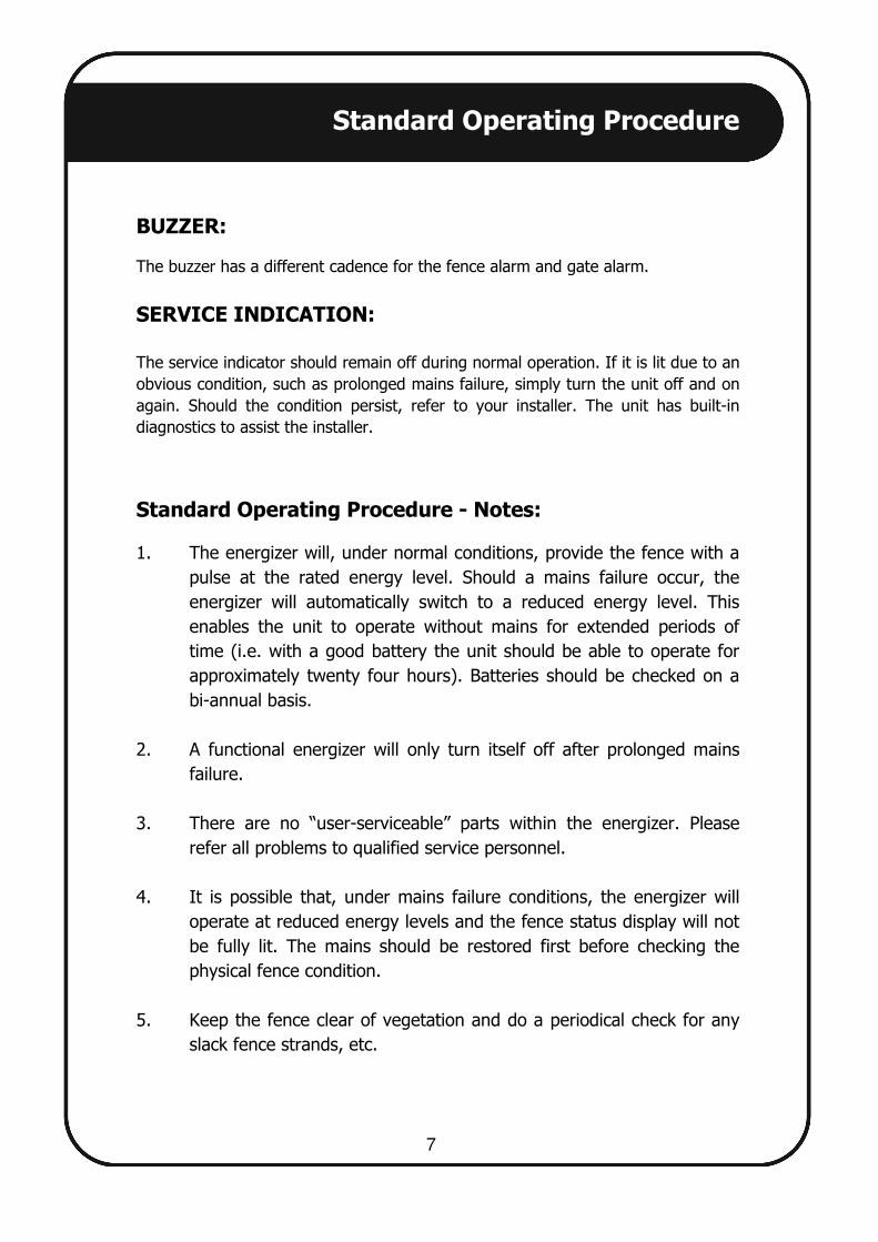
Standard Operating Procedure - Notes:
1. The energizer will, under normal conditions, provide the fence with a
pulse at the rated energy level. Should a mains failure occur, the
energizer will automatically switch to a reduced energy level. This
enables the unit to operate without mains for extended periods of
time (i.e. with a good battery the unit should be able to operate for
approximately twenty four hours). Batteries should be checked on a
bi-annual basis.
2. A functional energizer will only turn itself off after prolonged mains
failure.
3. There are no “user-serviceable” parts within the energizer. Please
refer all problems to qualified service personnel.
4. It is possible that, under mains failure conditions, the energizer will
operate at reduced energy levels and the fence status display will not
be fully lit. The mains should be restored first before checking the
physical fence condition.
5. Keep the fence clear of vegetation and do a periodical check for any
slack fence strands, etc.
BUZZER:
The buzzer has a different cadence for the fence alarm and gate alarm.
SERVICE INDICATION:
The service indicator should remain off during normal operation. If it is lit due to an
obvious condition, such as prolonged mains failure, simply turn the unit off and on
again. Should the condition persist, refer to your installer. The unit has built-in
diagnostics to assist the installer.

Standard Operating Procedure - LEDs
8
The status of the energizer and the fence
is displayed on the front panel of the
energizer, as follows:
Under normal operating conditions:
Conditions that if ignored will sound the alarm:
Mains present, battery charging
Fence energized
No fence alarm
No gate alarm
No service condition
If all are flashing, fence is
operating correctly
Restore mains – see Note 1
Turn energizer on – see Note 2
Alarm condition
Alarm condition
Possible installer intervention required – see Note 3
Fence good
Concern – see Note 4
Service fence – see note 4
Service fence
Alarm/Fence faulty

Features & Functions
9
INTEGRATED UNIT: For energizers designed from a security perspective, the fence monitoring is an
integral part of the product. The energizer is an integrated energizer, battery
charger and fence monitor with a siren and strobe light output.
LIGHTNING PROTECTION: The mains and high voltage outputs are protected against lightning and power
surges. It also protects the unit against abnormally high potential differences
between the high voltage and mains ground.
REMOTE KEY-SWITCH: The energizer can be wired to a remote on/off switch. There is only one external
input and the selection of gate, remote on/off or low/high voltage is exclusive.
GATE INPUT: Gate delay entry of four minutes, one minute (Wizord 2 only) or immediate entry
alarm.
HIGH/LOW VOLTAGE: The energizer (Wizord 2 only) can be switched between low/high voltage mode.
EARTH LOOP MONITORING: For additional security, the facility to use earth loop monitoring is provided for.
EXTENDED OPERATION DURING MAINS FAILURE:
The unit detects the mains failure and reduces the fence output energy.
AUXILIARY 12VDC OUTPUT: A 12 Volts DC fused output is available to supply any auxiliary equipment like a
radio remote receiver. The current must not exceed 0.5 amps.
SIREN OUTPUT: 12VDC output for siren available.
STROBE LIGHT OUTPUT: 12VDC output for strobe light available.
WEATHER PROOF HOUSING: The unit enclosure is made of high quality weather resistant material.
ARMED RESPONSE RADIO CONNECTABLE: The system has the facility to be connected to an armed response radio.
BATTERY BACKUP: The unit is supplied standard with a 12V 7AH rechargeable battery.

10
IEC Safety Information
• The Energizer is fully compliant to IEC 60335-2-76.
• There are no user serviceable parts inside the energizer.
• If the supply cord is damaged, it must be replaced by the manufacturer,
its service agent, or similar qualified persons in order to avoid a hazard.
• This appliance is not intended for use by persons (including children)
with reduced physical, sensory or mental capabilities, or lack of
experience and knowledge, unless they have been given supervision or
instruction concerning use of the appliance by a person responsible for
their safety.
• Electric fencing can be lethal. Avoid head contact with the fence.
Ask the installer to explain the options of current limiting resistors.
Rev 1.5, 4 February 2016
Updated for Wizord 4i
Rev 1.6, 20 June 2016
Combined Wizord 4i and Wizord 2
Print Code: MO 025