wj-sxb151 - panasonic€¦ · installation of multiplexer board wj-sxb151 the features of...
TRANSCRIPT
Before attempting to connect or operate this product,please read these instructions carefully and save this manual for future use.
Multiplexer Board
Model No. WJ-SXB151
WARNING:• All work related to the installation of this product should be made by qualified service personnel or system installers.
■ General ................................................................................................................. 2■ Precautions ........................................................................................................... 2■ Procedure Flow ..................................................................................................... 2
HARDWARE PREPARATION .................................................................................... 3■ Installation of Multiplexer Board WJ-SXB151 ....................................................... 3■ Connection with WJ-HD100 Series or Time-lapse VCR ....................................... 5
FIRMWARE UPDATE ................................................................................................ 6■ Installation of SX150A Program Writer .................................................................. 6■ Firmware Update of SX150A Program Writer ....................................................... 6■ Error List ............................................................................................................... 8
TROUBLESHOOTING .............................................................................................. 9
■ Specifications ..................................................................................................... 10■ Accessories ........................................................................................................ 10
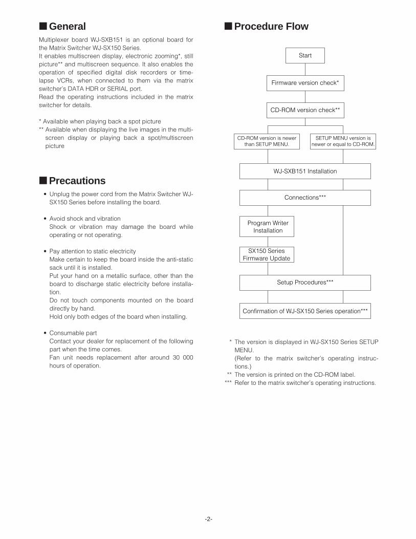
■ Procedure Flow
* The version is displayed in WJ-SX150 Series SETUPMENU.(Refer to the matrix switcher’s operating instruc-tions.)
** The version is printed on the CD-ROM label.*** Refer to the matrix switcher’s operating instructions.
-2-
■ Precautions• Unplug the power cord from the Matrix Switcher WJ-
SX150 Series before installing the board.
• Avoid shock and vibrationShock or vibration may damage the board whileoperating or not operating.
• Pay attention to static electricityMake certain to keep the board inside the anti-staticsack until it is installed.Put your hand on a metallic surface, other than theboard to discharge static electricity before installa-tion.Do not touch components mounted on the boarddirectly by hand.Hold only both edges of the board when installing.
• Consumable partContact your dealer for replacement of the followingpart when the time comes.Fan unit needs replacement after around 30 000hours of operation.
■ GeneralMultiplexer board WJ-SXB151 is an optional board forthe Matrix Switcher WJ-SX150 Series.It enables multiscreen display, electronic zooming*, stillpicture** and multiscreen sequence. It also enables theoperation of specified digital disk recorders or time-lapse VCRs, when connected to them via the matrixswitcher’s DATA HDR or SERIAL port.Read the operating instructions included in the matrixswitcher for details.
* Available when playing back a spot picture** Available when displaying the live images in the multi-
screen display or playing back a spot/multiscreenpicture

-3-
HARDWARE PREPARATION■ Installation of Multiplexer
Board WJ-SXB151● The Features of Multiplexer Board
WJ-SXB151Multiplexer Board WJ-SXB151 is an optional accessoryspecified for Matrix Switcher WJ-SX150 Series.The board installation will add the following functions tothe matrix switcher.
• A monitor can display up to 16 camera images inmultiscreen segments. (Multiscreen output)A desired image can be displayed as a still picture.(Still output)
• The matrix switcher can detect a moving object withthe brightness change and send an alarm to theexternal equipments. (Motion detector)
• The matrix switcher can multiplex the images of allthe cameras connected to Digital Disk RecorderWJ-HD100 Series or a time-lapse VCR.
• When an alarm becomes active, the accompaniedimage can be recorded by priority. (Alarm priorityrecording).
• The playback of the specified camera image whilethe alarm priority recording is available.
• When playing back the multiplexed images, spotoutput (displaying of a selected image's display) orthe multiscreen output is available.
Notes:• When using Digital Disk Recorder WJ-HD500 or
WJ-HD200 Series, all the functions related toMultiplexer Board WJ-SXB151 becomes unavail-able.
• To use these functions, the setup through WJ-SX150 Series SETUP MENU (OSD) and WJ-SX150 Series Administrator Console is neces-sary as well as the installation. For details, referto the operating instructions of the matrix switch-er.
● Installation procedures1. Disconnect the matrix switcher's power plug from
the outlet.2. Open the top cover by removing 11 screws and
sliding it backward. (Refer to the illustration.)
3. Install the cooling fan.q Open the blank panel at the right side of the
back panel.Remove the two screws. (Refer to the illustra-tion.)
w Remove the 3P connector attached to CN14,and connect the power cord of the cooling fanto CN14.
-4-
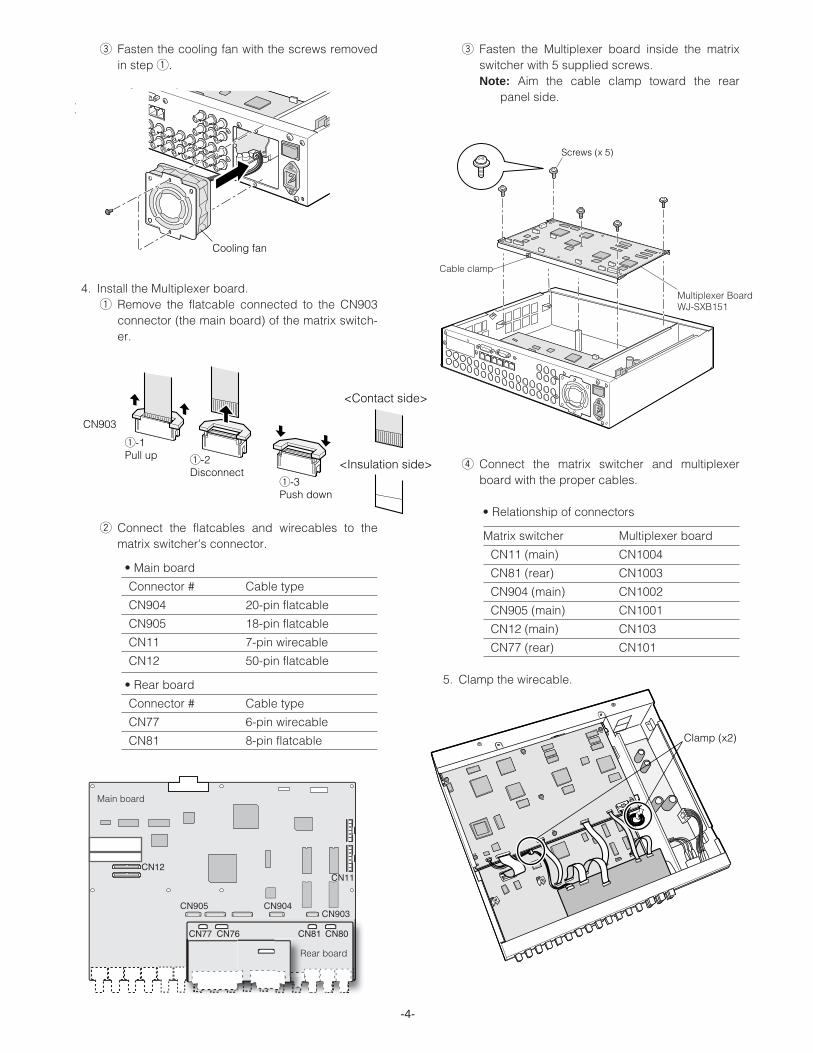
e Fasten the cooling fan with the screws removedin step q.
4. Install the Multiplexer board.q Remove the flatcable connected to the CN903
connector (the main board) of the matrix switch-er.
w Connect the flatcables and wirecables to thematrix switcher's connector.
• Main board
Connector # Cable type
CN904 20-pin flatcable
CN905 18-pin flatcable
CN11 7-pin wirecable
CN12 50-pin flatcable
• Rear board
Connector # Cable type
CN77 6-pin wirecable
CN81 8-pin flatcable
e Fasten the Multiplexer board inside the matrixswitcher with 5 supplied screws.Note: Aim the cable clamp toward the rear
panel side.
r Connect the matrix switcher and multiplexerboard with the proper cables.
• Relationship of connectors
Matrix switcher Multiplexer board
CN11 (main) CN1004
CN81 (rear) CN1003
CN904 (main) CN1002
CN905 (main) CN1001
CN12 (main) CN103
CN77 (rear) CN101
5. Clamp the wirecable.
-5-
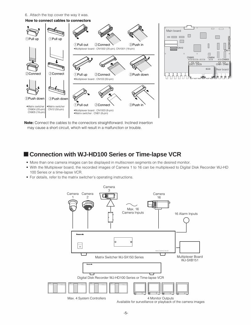
■ Connection with WJ-HD100 Series or Time-lapse VCR • More than one camera images can be displayed in multiscreen segments on the desired monitor.• With the Multiplexer board, the recorded images of Camera 1 to 16 can be multiplexed to Digital Disk Recorder WJ-HD
100 Series or a time-lapse VCR.• For details, refer to the matrix switcher’s operating instructions.
Matrix Switcher WJ-SX
OPERATE
For Matrix Switcher (WJ-SX150)
System Controller
For Matrix Switcher (WJ-SX150)
System Controller
For Matrix Switcher (WJ-SX150)
System Controller
For Matrix Switcher (WJ-SX150)
System Controller
OPERAOPERATE LED WILL BLINKTE LED WILL BLINKIF COOLING FIF COOLING FAN MALFUNCTIONSAN MALFUNCTIONS
6. Attach the top cover the way it was.
-6-
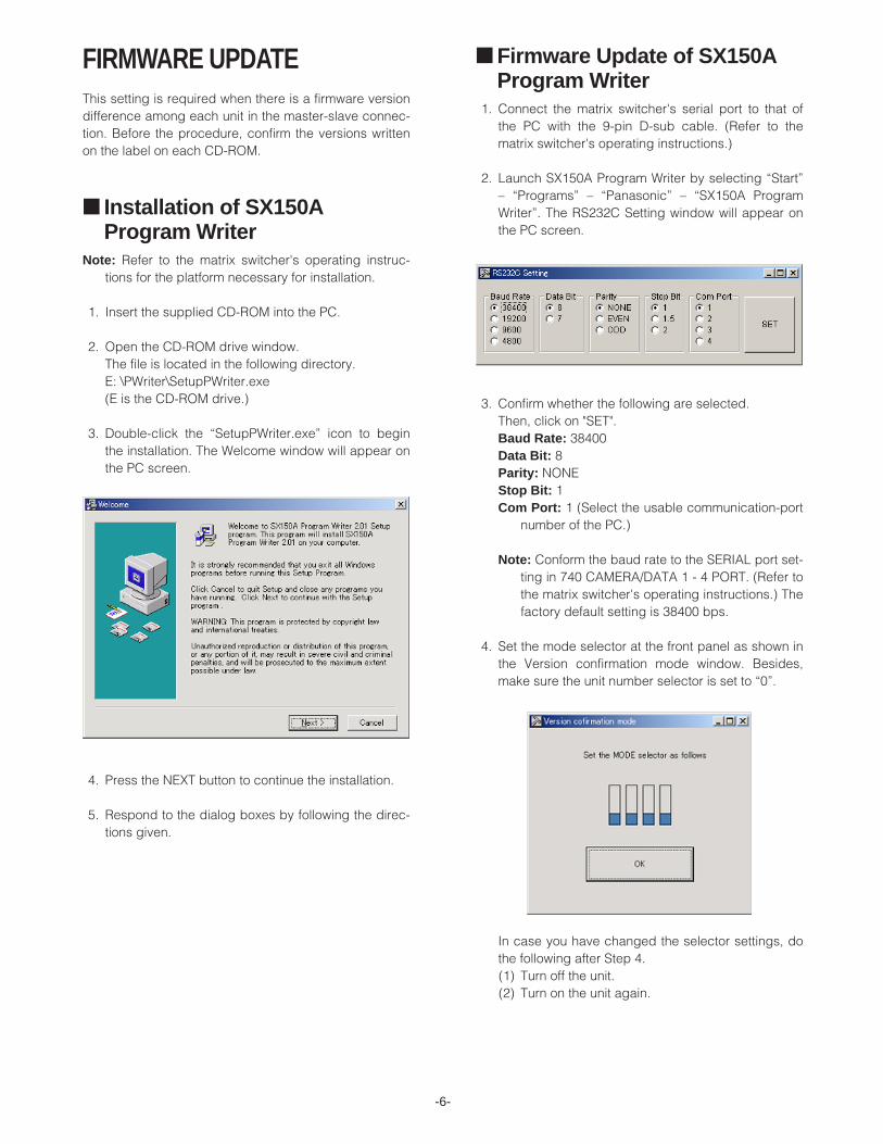
FIRMWARE UPDATEThis setting is required when there is a firmware versiondifference among each unit in the master-slave connec-tion. Before the procedure, confirm the versions writtenon the label on each CD-ROM.
■ Installation of SX150AProgram Writer
Note: Refer to the matrix switcher's operating instruc-tions for the platform necessary for installation.
1. Insert the supplied CD-ROM into the PC.
2. Open the CD-ROM drive window.The file is located in the following directory.E: \PWriter\SetupPWriter.exe(E is the CD-ROM drive.)
3. Double-click the “SetupPWriter.exe” icon to beginthe installation. The Welcome window will appear onthe PC screen.
4. Press the NEXT button to continue the installation.
5. Respond to the dialog boxes by following the direc-tions given.
■ Firmware Update of SX150AProgram Writer
1. Connect the matrix switcher's serial port to that ofthe PC with the 9-pin D-sub cable. (Refer to thematrix switcher's operating instructions.)
2. Launch SX150A Program Writer by selecting “Start”– “Programs” – “Panasonic” – “SX150A ProgramWriter”. The RS232C Setting window will appear onthe PC screen.
3. Confirm whether the following are selected.Then, click on "SET".Baud Rate: 38400Data Bit: 8Parity: NONEStop Bit: 1Com Port: 1 (Select the usable communication-port
number of the PC.)
Note: Conform the baud rate to the SERIAL port set-ting in 740 CAMERA/DATA 1 - 4 PORT. (Refer tothe matrix switcher's operating instructions.) Thefactory default setting is 38400 bps.
4. Set the mode selector at the front panel as shown inthe Version confirmation mode window. Besides,make sure the unit number selector is set to “0”.
In case you have changed the selector settings, dothe following after Step 4.(1) Turn off the unit.(2) Turn on the unit again.
-7-
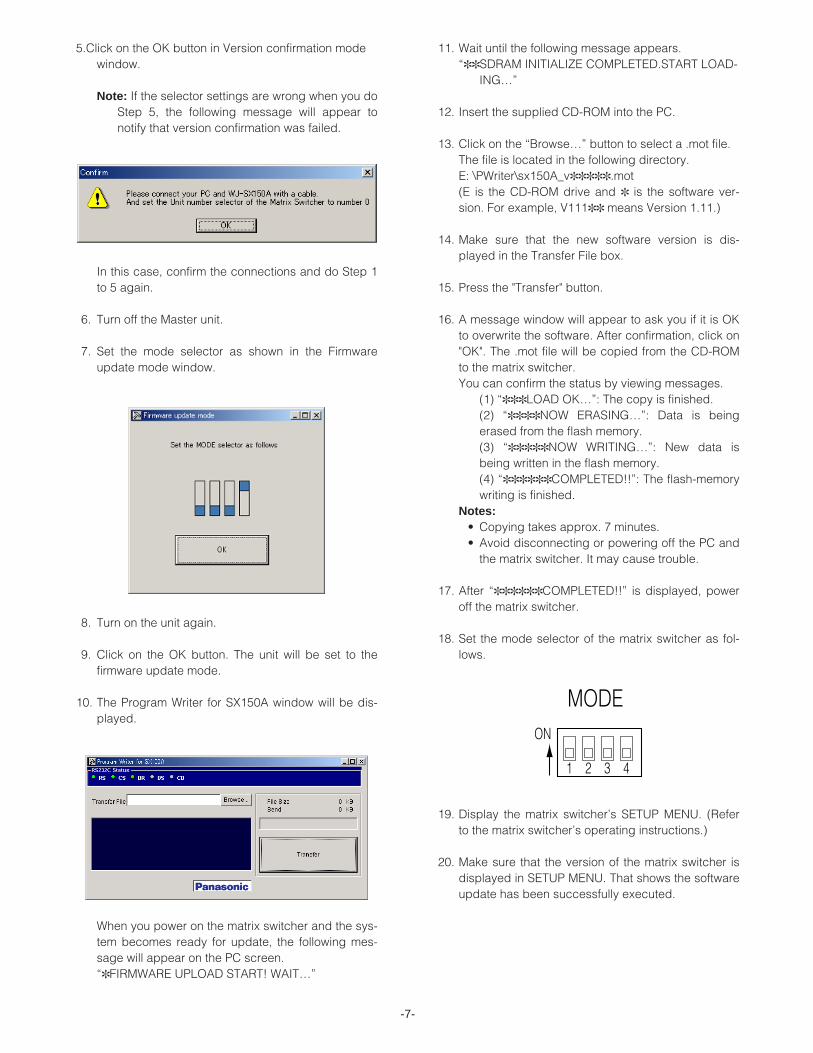
5.Click on the OK button in Version confirmation modewindow.
Note: If the selector settings are wrong when you doStep 5, the following message will appear tonotify that version confirmation was failed.
In this case, confirm the connections and do Step 1to 5 again.
6. Turn off the Master unit.
7. Set the mode selector as shown in the Firmwareupdate mode window.
8. Turn on the unit again.
9. Click on the OK button. The unit will be set to thefirmware update mode.
10. The Program Writer for SX150A window will be dis-played.
When you power on the matrix switcher and the sys-tem becomes ready for update, the following mes-sage will appear on the PC screen.“✽ FIRMWARE UPLOAD START! WAIT…”
11. Wait until the following message appears.“✽✽ SDRAM INITIALIZE COMPLETED.START LOAD-
ING…”
12. Insert the supplied CD-ROM into the PC.
13. Click on the “Browse…” button to select a .mot file.The file is located in the following directory.E: \PWriter\sx150A_v✽✽✽✽✽ .mot (E is the CD-ROM drive and ✽ is the software ver-sion. For example, V111✽✽ means Version 1.11.)
14. Make sure that the new software version is dis-played in the Transfer File box.
15. Press the "Transfer" button.
16. A message window will appear to ask you if it is OKto overwrite the software. After confirmation, click on"OK". The .mot file will be copied from the CD-ROMto the matrix switcher.You can confirm the status by viewing messages.
(1) “✽✽✽ LOAD OK…”: The copy is finished.(2) “✽✽✽✽ NOW ERASING…”: Data is beingerased from the flash memory.(3) “✽✽✽✽✽ NOW WRITING…”: New data isbeing written in the flash memory.(4) “✽✽✽✽✽✽ COMPLETED!!”: The flash-memorywriting is finished.
Notes:• Copying takes approx. 7 minutes.• Avoid disconnecting or powering off the PC and
the matrix switcher. It may cause trouble.
17. After “✽✽✽✽✽✽ COMPLETED!!” is displayed, poweroff the matrix switcher.
18. Set the mode selector of the matrix switcher as fol-lows.
19. Display the matrix switcher’s SETUP MENU. (Referto the matrix switcher’s operating instructions.)
20. Make sure that the version of the matrix switcher isdisplayed in SETUP MENU. That shows the softwareupdate has been successfully executed.
-8-
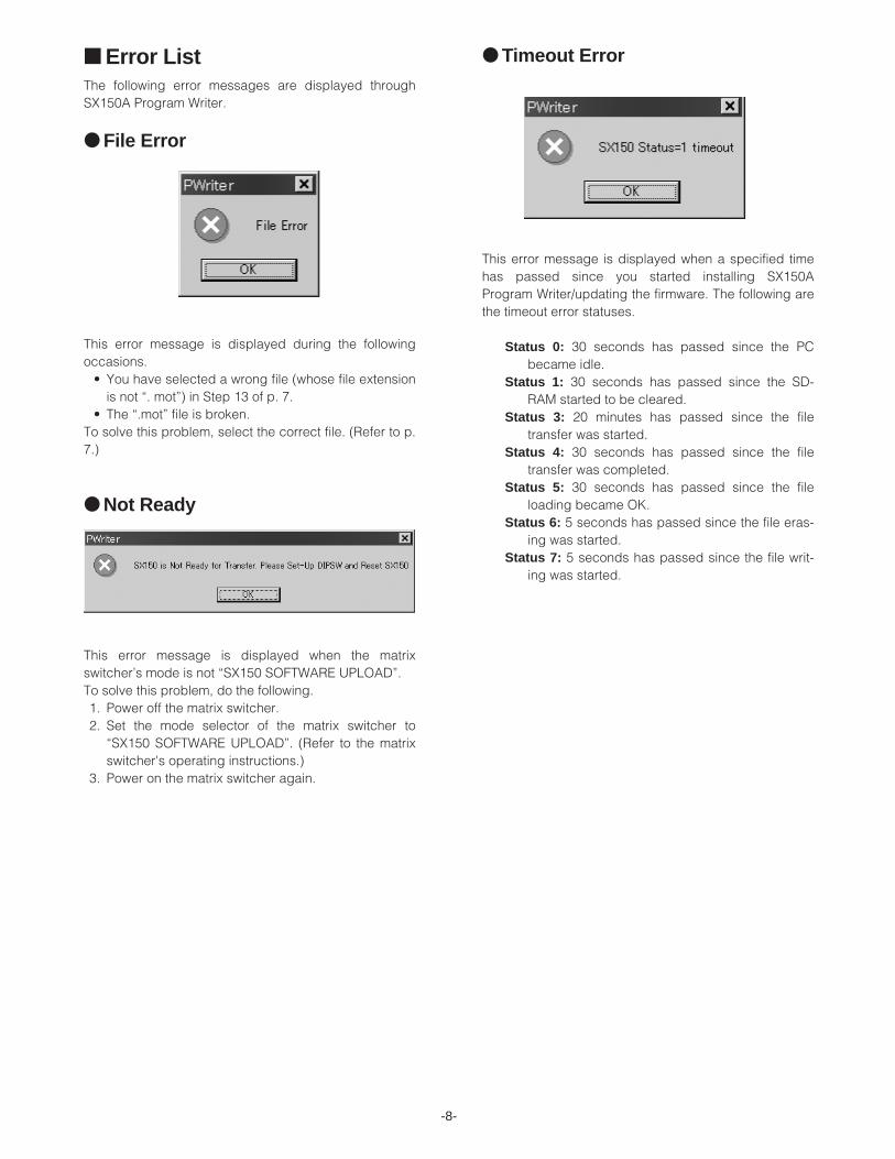
■ Error ListThe following error messages are displayed throughSX150A Program Writer.
● File Error
This error message is displayed during the followingoccasions.
• You have selected a wrong file (whose file extensionis not “. mot”) in Step 13 of p. 7.
• The “.mot” file is broken.To solve this problem, select the correct file. (Refer to p.7.)
● Not Ready
This error message is displayed when the matrixswitcher’s mode is not “SX150 SOFTWARE UPLOAD”.To solve this problem, do the following.1. Power off the matrix switcher.2. Set the mode selector of the matrix switcher to
“SX150 SOFTWARE UPLOAD”. (Refer to the matrixswitcher's operating instructions.)
3. Power on the matrix switcher again.
● Timeout Error
This error message is displayed when a specified timehas passed since you started installing SX150AProgram Writer/updating the firmware. The following arethe timeout error statuses.
Status 0: 30 seconds has passed since the PCbecame idle.
Status 1: 30 seconds has passed since the SD-RAM started to be cleared.
Status 3: 20 minutes has passed since the filetransfer was started.
Status 4: 30 seconds has passed since the filetransfer was completed.
Status 5: 30 seconds has passed since the fileloading became OK.
Status 6: 5 seconds has passed since the file eras-ing was started.
Status 7: 5 seconds has passed since the file writ-ing was started.
-9-
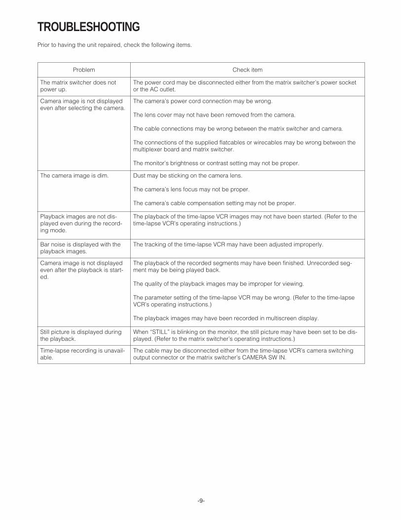
TROUBLESHOOTINGPrior to having the unit repaired, check the following items.
Camera image is not displayedeven after the playback is start-ed.
Time-lapse recording is unavail-able.
The matrix switcher does notpower up.
Camera image is not displayedeven after selecting the camera.
Problem Check item
The power cord may be disconnected either from the matrix switcher’s power socketor the AC outlet.
The camera’s power cord connection may be wrong.
The lens cover may not have been removed from the camera.
The cable connections may be wrong between the matrix switcher and camera.
The connections of the supplied flatcables or wirecables may be wrong between themultiplexer board and matrix switcher.
The monitor’s brightness or contrast setting may not be proper.
The camera image is dim. Dust may be sticking on the camera lens.
The camera’s lens focus may not be proper.
The camera’s cable compensation setting may not be proper.
Playback images are not dis-played even during the record-ing mode.
The playback of the time-lapse VCR images may not have been started. (Refer to thetime-lapse VCR’s operating instructions.)
Bar noise is displayed with theplayback images.
The tracking of the time-lapse VCR may have been adjusted improperly.
The playback of the recorded segments may have been finished. Unrecorded seg-ment may be being played back.
The quality of the playback images may be improper for viewing.
The parameter setting of the time-lapse VCR may be wrong. (Refer to the time-lapseVCR’s operating instructions.)
The playback images may have been recorded in multiscreen display.
Still picture is displayed duringthe playback.
When “STILL” is blinking on the monitor, the still picture may have been set to be dis-played. (Refer to the matrix switcher’s operating instructions.)
The cable may be disconnected either from the time-lapse VCR’s camera switchingoutput connector or the matrix switcher’s CAMERA SW IN.
-10-
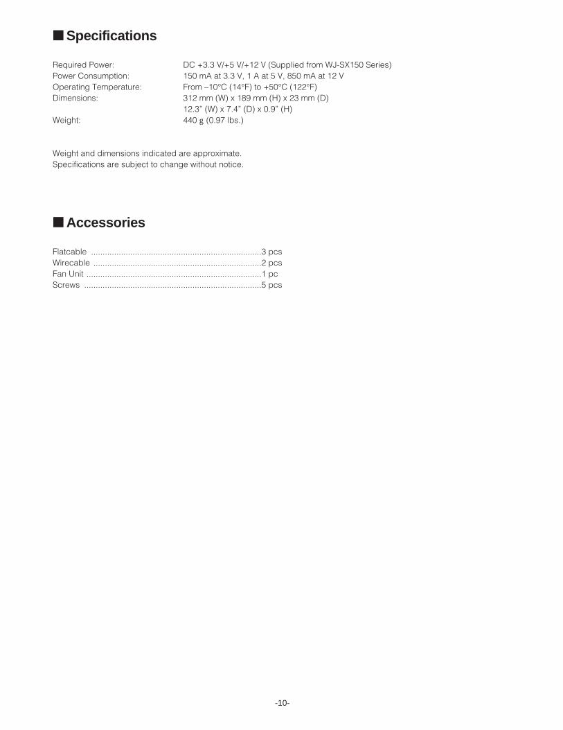
■ Specifications
Required Power: DC +3.3 V/+5 V/+12 V (Supplied from WJ-SX150 Series)Power Consumption: 150 mA at 3.3 V, 1 A at 5 V, 850 mA at 12 VOperating Temperature: From –10°C (14°F) to +50°C (122°F)Dimensions: 312 mm (W) x 189 mm (H) x 23 mm (D)
12.3” (W) x 7.4” (D) x 0.9” (H)Weight: 440 g (0.97 lbs.)
Weight and dimensions indicated are approximate.Specifications are subject to change without notice.
■ Accessories
Flatcable ..........................................................................3 pcsWirecable .........................................................................2 pcsFan Unit ............................................................................1 pcScrews .............................................................................5 pcs