wk contents -...
TRANSCRIPT

WK
Contents
Point Description PageNo. No.
0 Introduction 1
1 Pump construction 11.1 Casing 11.2 Rotor 11.3 Bearing arrangement 21.4 Lubrication 31.4.1 Oil lubrication 31.4.2 Grease lubrication 41.5 Shaft seal 41.5.1 Stuffing boxes 41.5.1.1 Cooling liquid for stuffing boxes 51.5.1.2 Packing the stuffing boxes 51.5.1.3 Packing material 71.5.2 Mechanical seals 71.6 Coupling 7
2 Mode of operation of pump 7
3 Drive 8
4 Transport 8
5 Painting 8
6 Condition of equipment as supplied 8
7 Accessories 9
8 Installing the pumping set 98.1 Description of site prior to
commencement of erection 98.2 Installation and preliminary levelling up 98.3 Aligning the coupling 98.4 Grouting in the baseplate 108.5 Final alignment 10
9 Piping 119.1 Suction lift line and positive
Suction head line 119.1.1 Strainers in suction head line/suction lift line 119.2 Isolating valves 129.3 Non-return valves 129.3.1 Automatic recirculation valve 129.4 Final coupling check 139.5 Measuring instruments 13
10 Commissioning 1310.1 Preliminary remarks regarding
commissioning 1310.2 Start-up 1310.3 Operation and supervision of pump 14
Point Description PageNo. No.
10.4 Shutting the pump down 1410.5 Preserving the pump 1510.6 Sending the pump back to our Works 15
11 Dismantling the pump 1511.1 Preparations prior to dismantling 1511.2 Dismantling the bearing 1511.2.1 Dismantling the drive end bearing 1511.2.2 Dismantling the end side bearing 1611.2.2.1 Standard bearing construction 1611.2.2.2 Heavy duty bearing construction 1711.3 Removing the shaft seal 1711.3.1 Soft-packed stuffing box construction 1711.4 Dismantling the pump body 1711.5 Inspection of individual pump components 1911.6 Dynamic balancing of pump rotor 20
12 Assembly of pump 2012.1 Preparations prior reassembly 2012.2 Assembling the pump body 2012.3 Assembly of shaft seal 2212.3.1 Pump construction with soft-packed
stuffing box 2212.4 Assembly of bearings 2312.4.1 Assembly of end side bearing 2312.4.2 Assembly of drive end bearing 23
13 Operating troubles, causes and remedies 2513.1 Operating troubles 2513.2 Causes for damage 2513.3 Suggested remedies 26
14 Spare parts 27
15 Check list 2815.1 Pre-requisites for initial commissioning 2815.2 Initial start-up with cold water 2815.3 Priming the boiler 2815.4 Initial operation with hot fluid 2815.5 Supervision of operations & maintenance 28
16 Sectional drawings and list ofcomponents 29Balancing liquid piping 31

WK
0. Introduction
WK pumps are High Pressure Horizontal Centrifugal Pumps.In accordance with the latest state of the art of pump designand construction, our pumps combine favourable hydrauliccharacteristics with a long service life, reliability of operationand simple maintenance and operation.
A pre-requisite for trouble-free operation of the pumps is thecareful observance of the recommendations contained in thisoperating instruction manual. It should therefore, always be atthe disposal of the personnel entrusted with the erection,maintenance and operation of the pump.
It goes without saying that the pumps should only be operatedunder the duty conditions specified (see data sheet). The termsof our Guarantee naturally apply within this range of conditions.Our Guarantee will become invalid if the pumps are dismantled,either completely or partially, without our prior consent. Thefirst assembly and dismantling of the pump should be carriedout by skilled fitters and erectors, and this also applies to theinitial start-up (commissioning) of the pumping set.
1. Pump Construction
(For item numbers, see under section 16, Sectional drawings.)
1.1 Casing
WK high pressure centrifugal pumps are single or multistagecentrifugal pumps with a radially split casing. This consists ofthe suction and discharge casing (106 and 107) together witha number of stage casings (108). If the extraction of a givenquantity of the liquid pumped at one of more intermediatepressures is required, the corresponding stage casings canbe provided with extraction (Bleed off) nozzles. The individualcasing components are sealed off against one another by flatgaskets (400.2) or by ‘O’ rings (412) and clamped together byconnection rods (905). The diffusers (171.1 and 171.2) arearranged in the stage casings and in the discharge casingrespectively (108 and 107 respectively). They are centered inthe casings at their outer periphery and secured againsttwisting.
The stuffing box housings (451) and bearing housing (350)are flanged onto the suction and discharge casing respectively(106 and 107) and attached by studs (902.1). The stuffing boxhousings (451) are sealed off from the suction and dischargecasings respectively (106 and 107) by a flat gasket (400.3).On pumps fitted with special hot water stuffing boxes or withmechanical seals, the shaft seal is surrounded by a cooling
Fig. 1
water compartment, which is sealed off against atmosphereby the stuffing box housing cover (165) with flat gasket (400.3)and O-ring (412.4) (See Fig. 2)
Fig. 2 Stuffing box housing with cooling compartment cover
Depending on the number of stages and on the temperatureof the product pumped, the pump feet are integrally cast ontothe suction and discharge casings (106 and 107) either at thebottom, or at shaft centerline height. The suction nozzle canbe arranged to point horizontally to the left or right hand side,or vertically upwards, if the pump feet are arranged at thebottom of the pump; if they are arranged at shaft centerlingheight, the suction nozzle can only be arranged to pointvertically upwards the discharge nozzle points radially upwardson both types of pump feet arrangement.
In order to achieve a favourable NPSH required, the suctionnozzles on all sizes of pumps are made one nominal size largerthan the discharge nozzles. The flange construction is specifiedin the data sheet.
1.2 Rotor
All the rotating components assembled on the shaft make upthe complete pump rotor (See Fig. 3 and 4)
The shaft (210) transmits the torque generated by the driveonto the impellers. The impellers (230) are mounted issequence on shaft (210), and they all point in the samedirection. They are secured against twisting by keys.
The narrow clearance gap between impeller neck and casingwearing ring (502) at the suction and discharge end of eachimpeller prevents the equalization of presure between onestage and the next.
The shaft (210) is protected inside the pump against attack bythe fluid pumped by means of spacer sleeve (525.1/2) anddistance bushes stage (521). The distance bushes/stage alsoserve to locate the impellers axially on the shaft. The shaft(210) is protected by the shaft protection sleeves (524.1/.2) inthe region of the shaft seal. These protection sleeves arescrewed onto shaft (210) by means of screw threads withopposed hand to the direction of rotation of the shaft.
Fig. 3 Assembled rotor
412.3 412.4 461.1
452
165
350
400.3
7A/7E
400.3
451
524.2(524.1)
1

WK
Fig. 4 Dismantled rotor
In order to balance the axial thrust, throttling passages arearranged at the impeller necks at the suction and dischargeend of each impeller, and additional balancing holes areprovided in the impeller necks at the discharge end(See Fig. 5).
A fixed bearing absorbs the residual axial thrust generatedand also locates the rotor in the axial position; in the standardbearing construction, this bearing consists of a deep grooveball bearing (321) and in the pump construction with heavyduty bearing bracket, it consists of two angular contact ballbearings (320).
1.3 Bearing Arrangement
WK pumps are fitted with different types of beaings and bearinghousing, depending on the differential head (generatedpressure) of the pump. In the case of low differential heads,the standard bearing construction is provided. In the case ofhigher total heads, the heavy duty bearing construction isprovided to absorb the increased residual thrust.
The pump manufacturer decides which type of bearingarrangement shall be provided.
Fig. 6 Individual bearing components (drive end)
Part 1 = Outer race with cage and rollersPart 2 = Adaptor SleevePart 3 = Inner bearing racePart 4 = Locking WasherPart 5 = Withdrawal Nut
Standard Bearing Construction :
Drive end : 1 Cylindrical roller bearing in accordance with DIN5412 (see Fig. 6) with adaptor sleeve in accordance with DIN
5412 and standard bearing bracket (No adaptor sleeveprovided on pump size 150).
End side : 1 deep groove ball bearing in accordance with DIN625 and standard bearing housing (see Figs. 7 and 8).
Heavy Duty Bearing Construction :
Drive end : Same as atandard bearing construction. Endside : 2 matched angular contact ball bearings in accordancewith DIN 628; X arrangement and heavy duty bearing bracket(see Fig. 9).
Fig. 9 Bearing construction with heavy duty bearingbracket size 150.
Fig. 7 Bearing construction, size 40 to 125
361 920.4 321 350 350 731.2 322 400.4 901.2
400.4 903.4(13B)
507507 52-1 360 210
Fig. 8 Bearing construction, size 150
903.12 400.4 920.4 350 525.4 507 525.4 350 360
361 543 321 932 507 932 322 543Drive end
Fig. 5 Rotor
901.3 361 913 350.2 412.7 507210932508320320923
412.7 644 644 360.2902.3
525.5720.3(8B)
901.4525.8160
543400.5903.5(13B)
2

WK
Standard Construction
Pump size 40 50 65 80 100 125 150
Drive end :cylindrical roller bearing NU 206 K NU 207 K NU 207 K NU 208 K NU 208 K NU 210 K NU 410designation in accordance C 3 C 3 C 3 C 3 C 3 C 3 C 3with DIN 5412
Adaptor sleeve inaccordance with DIN 5412 H 206 H 207 H 207 H 208 H 208 H 210 ---
Non Drive end :Deep groove ball bearingdesignation in accordance 6403/C 3 6404/C 3 6404/C 3 6405/C 3 6405/C 3 6405/C 3 6410/C 3with DIN 625
Oil fill in litres 0.16 0.18 0.18 0.25 0.25 0.28 0.45
Heavy Duty Bearing Bracket
Pump size 40 50 65 80 100 125 150
Drive end :cylindrical roller bearing NU 206 K NU 207 K NU 207 K NU 208 K NU 208 K NU 210 K NU 410designation in accordance C 3 C 3 C 3 C 3 C 3 C 3 C 3with DIN 5412
Adaptor sleeve inaccordance with DIN 5415 H 206 H 207 H 207 H 208 H 208 H 210 ---
Non Drive end :Angular contact ball bearingDin 628, 7305 BG 7306 BG 7306 BG 7307 BG 7307 BG 7309 BG 7310 BGmatched pair, X arrangement 7305 B. UA 7306 B. UA 7306 B. UA 7307 B. UA 7307 B. UA 7309 B. UA 7310 B. UAManufacturer SKF
FAG
Oil fill in litres 0.65 0.70 0.70 0.90 0.90 1.2 1.2
Drive at both Ends
Pump size 40 50 65 80 100 125 150
Suction side :cylindrical roller bearing NU 206 K NU 207 K NU 207 K NU 208 K NU 208 K NU 210 K NU 410designation in accordance C 3 C 3 C 3 C 3 C 3 C 3 C 3with DIN 5412
Adaptor sleeve inaccordance with DIN 5412 H 206 H 207 H 207 H 208 H 208 H 210 ---
Discharge side :Deep groove ball bearingdesignation in accordance 6305/C 3 6306/C 3 6306/C 3 6307/C 3 6307/C 3 6308/C 3 6410/C 3with DIN 625
Oil fill in litres 0.16 0.18 0.18 0.25 0.25 0.28 0.45
Fig. 10 Bearing end oil requirement table
In case of the pump construction with drive at both ends, thebearing arrangement at the suction end corresponds to thestandard construction. At the discharge end, deep groove ballbearings in accordance with DIN 625 are fitted, but they are ofbearing series 63.
See Fig. 10 ‘‘Bearing and oil requirement table’’ for precisebearing designation and size for the individual pump sizes.Splash ring (507) on shaft (210) prevent the penetration ofany leakage liquid from the stuffing box into the bearinghousing.
1.4 Lubrication
1.4.1 Oil Lubrication
Standard construction WK pumps are provided with oil splashlubrication. The antifriction bearings are slightly submerged inthe oil sump, ensuring perfectly satisfactory lubrication at alltimes. The max. oil level is automatically attained during toppingup when oil starts pouring out of the over-flow holes in thebearing covers (360/361).
On request, we can fit constant level oilers (638), which willnecessitate the sealing of the shaft against the bearing bracketby means of felt rings (422.1) (See Fig. 11 to 13).
3

WK
Oil Quality : Machinery oil possessing good air releaseproperties and corrosion prevention characteristics; kinematicviscosity 36 cSt approx. = 4.80E at 500C; flash point 1500Cminimum; pour point lower than -200C.
Lubrication times : First oil change after the first 500 hours ofoperation, subsequent oil changes after every 3000 hours ofoperation approx., but at least once a year.
Fig. 11 Oil splash lubrication
Fig. 13 Constant level oiler viewed from X
Topping up of the oil fill at least once a month.
The bearing temperature may be allowed to rise up to 400Cabove room temperature, but should not exceed 800C.
1.4.2 Grease Lubrication
(Cannot be provided on heavy duty bearing constructionpumps).
Portable (mobile) pumps, and pumps installed on board shiphave grease-lubricated bearings (See Fig. 14). Use a goodquality lithium soap ball and roller bearing grease, free of resinand acid, and possessing rust preventive properties. Thegrease should have a penetration number situated between 2and 3, corresponding to a worked penetration situated between2220 and 295 mm/10. Its drop point should be not less than1750C.
The bearing temperature may be allowed to rise up to 400Cabove room temperature, but should not exceed 800C. Thegrease fill will last for 15000 hours of operation i.e., for 2 yearsapprox. If the operating conditions are arduous, the bearingsshould be serviced once a year. A grease fill amounts to 10-20grammes of grease, depending on the pump size. The pumpbearings are packed with grease at our Works before despatch.
1.5 Shaft Seal
The shaft is sealed at its exits through the casings by softpackedstuffing boxes or by mechanical seals. If the pump is fitted withspecial stuffing boxes, mechanical seals can be fitted in lieu ofsoft packing (or vice versa) at any time during the service lifeof the pump, with a minimum of machining of the coolingcompartment covers. On the other hand, the fitting ofmechanical seals to pumps equipped with standard or hot watertype soft-packed stuffing boxes necesitates the fitting of newpump components. Particulars can be obtained from the pumpmanufacturer.
1.5.1 Stuffing Boxes
Soft-packed stuffing boxes reduce the flow of leakage liquid atthe clearance gap between casing and shaft protection sleevewhen the pressure inside the pump is higher than atmospheric.Conversely, on pumps which operate on suction lift, the soft-packed stuffing box prevents the ingress of air into the pump.Sealing is effected by means of soft packing (461.1) arrangedin a number of rings in the annular space between the stuffingbox housing (451) and the shaft protection sleeve (524.1/2)and lightly compressed by the stuffing box gland (452).
Caution : On pumps which have a high discharge pressure,the stuffing box at the discharge end is relieved of pressure,via a balance liquid line, down to the suction pressure, providedthat the differential pressure across the pump exceeds 20 bar.This ensures that the stuffing boxes at the suction and dischargeends of the pump have the same admission pressure. Thisarrangement applies to pump sizes 40 to 65 if the dischargepressure exceeds 20 bar and to pump sizes 80 to 150 if thedischarge pressure exceeds 15 bar.
Single stage pumps require no special pressure relief even athigh discharge pressures. The pressure is relieved via thebalance holes in the impeller.
Overflow hole
Oil sump
Fig. 12 Construction with constant level oiler and sealing ofthe bearing housing.
422.4 500.4 500.1 913 422.1
X
End side(Heavy duty bring bracket)
Drive end
638
Fig. 14 Grease lubricated bearing construction
731.2 636
4

WK
Soft-packed stuffing box, ‘‘Standard’’ (N) construction.Standard construction with 4 packing rings (461.1) used fortemperatures of the fluid pumped up to 1050C. The stuffingbox compartment cannot be cooled.
Soft-packed stuffing box, ‘‘Hot Water’’ (HW) construction.Construction with 4 packing rings (461.1) and cooling of thestuffing box compartment. Used for temperatures of the fluidpumped in excess of 1050C up to 2300C max.
Special stuffing box, ‘‘Extra-deep’’ (V) construction.Construction with 7 packing rings (461.1) and cooling of thestuffing box compartment, used mainly in process industryapplications.
Special stuffing box, ‘‘VSM’’ ConstructedVSM is the abbreviation (in German) of ‘‘Extra deep with lanternring at the centre’’.
Construction with 5 packing rings (461.1) and one seal casering (458) arranged at the centre of the packing compartment;used mainly for operation under vacuum or suction lift, andwhere malodorous fluids are pumped. For operation undervacuum, the lantern ring (458) is fed with a sealing liquid, andit prevents the ingress of air into the pump.
Special stuffing box, ‘‘VSH’’ constructed.VSH is the abbreviation (in German) for ‘‘Extra deep with sealcage ring at the bottom of the box’’. The construction with 5packing rings (461.1) and a seal cage ring (458) arranged atthe bottom of the packing compartment is used where fluidscontaining abrasive particles are pumped. The flushing liquid,which should be fed through the cage ring (458) at a pressureof at least 1 to 4 bar (max.) above the suction pressure,penetrates inside the pump and protects the stuffing boxpacking (461.1) against abrasive substances.
1.5.1.1 Cooling Liquid for Stuffing Boxes
Treated cooling water which does not tend to precipitate saltscausing hardness out of solution should be used as coolingliquid. The cooling water should be allowed to flow out freelyand visibly, so that it can be checked at any time in respect ofrate of flow and temperature. The temperature differentialbetween cooling water inlet and outlet should not exceed 100C.The max. permissible cooling water outlet temperature shouldnot exceed 500C. The cooling water pressure should be situatedbetween 1 bar min. and 10 bar max.
An isolating valve should be incorporated in the cooling watersupply line, to enable the rate of flow of cooling water to beadjusted, and the supply of cooling water to be turned off whenthe pump is shut down. The cooling water should only be turnedoff after the temperature of the fluid inside the pump hasdropped to below 800C.
1.5.1.2 Packing the Stuffing Boxes
Caution : The pump is despatched from our works with thestuffing boxes unpacked. An adequate quantity of packingmaterial is supplied loose with the pump. The stuffing box willonly be able to perform its vital function satisfactorily oncondition that it is carefully packed and properly maintainedas prescribed.
Before packing, thoroughly clean stuffing box gland (452),packing compartment and shaft protection sleeve (524.1/.2).
Fig. 15 ‘‘Standard’’ (N) construction stuffing box
412.3 461.1
452
350
400.3
451
524.2(524.1)
Fig. 16 ‘‘Hot Water’’ (HW) construction stuffing box
412.3 412.4 461.1
452
165
350
400.3
7A/7E
400.3
451
524.2(524.1)
Fig. 17 Special soft packed stuffing box ‘‘Extra deep’’ (V)
412.3 412.4 461.1
452
165
350
400.3
7A/7E
400.3
451524.2(524.1)
Fig. 18 Special stuffing box VSM
Fluids pumped :Operation under vacuumor pumping of malodorousfluids (ammonia andsolvents).
Sealing liquid consumption1 to 3 litres/hours approx.
412.3 412.4 461.1
452
165
350
400.3
10A/10E
400.3
451
524.2(524.1)
458
Fig. 19 Special stuffing box VSH.
Fluids :
Products containing abrasiveparticles, which must be keptaway from the stuffing boxpacking, so as not to erodethe latter (oils containingdiatomite (kieselguhr),fractions from catalyticcracking containing abrasivecatalyst particles).Flushing liquid consumption300 to 500 litres/hour approx.412.3 412.4 461.1
452
165
350
400.3
11E
400.3
451
524.2(524.1)
458
5

WK
Fig. 20 Cutting the packing rings of length.
To cut the packing rings to correct length, use a suitable woodencutting jig (we can supply same on request), to ensure that thepacking rings are of the correct length and that their ring buttscome into correct contact with one another (see Fig. 20).
If the packing rings are either too long or too short, the stuffingbox will not be able to perform its function properly. In the caseof asbestos-graphite packing material, the rubbing faces ofthe individual rings should be lightly coated with molybdenumdisulphide before insertion in the packing compartment. Thefirst packing ring is then inserted and pushed home into thecompartment with the aid of the stuffing box gland.
The following packing rings are then inserted into the packingcompartment one by one, making sure that the butt joint ofeach ring is offset 900 approx. in relation to the butt joint of thepreceding ring; the individual rings are pushed home into thepacking compartment with the aid of the stuffing box gland(see Fig. 21 and 22). The packing rings should only be pressedlightly against one another. They should not be inserted in thepacking compartment in such a way that a clear gap of 6 to 8mm is left at the outer end of the compartment for the positiveguidance of the stuffing box gland.
Fig. 22 Insertion of packing rings with the aid of the stuffingbox gland
Fig. 23 Tightening the stuffing box gland
The inserted packing rings should then be compressedmoderately with the aid of the stuffing box gland (452) and thenuts (see Fig. 23). Then the nuts should be slackened againby one to two complete turns, and thereafter tightened lightlyby hand. The correct and even seating of the stuffing box gland(452) should be checked when the pump is subjected to suctionpressure, by inserting a feeler gauge between the gland (452)and the shaft protection sleeve (524.1/.2).
In the case of the special stuffing boxes, a seal cage ring isalso inserted in the packing compartment, viz. at the centre ofthe compartment (between the packing rings) in the case ofconstruction ‘‘VSM’’, and at the bottom of the compartment inthe case of construction ‘‘VSH’’. In these cases, an informationplate (see Fig. 20) is affixed to the stuffing box housing, showingthe position of the lantern ring. The seal cage ring must registerbeneath the drilled hole in the stuffing box housing, to enablethe sealing of flushing liquid to flow through the hole and thering. The sealing or flushing liquid pressure should be 1 to 4bar above the pressure reigning in the packing compartmentof the stuffing box.
The packing of the stuffing boxes should be carried out withgreat care, to avoid an excessively high radial pressing forceof the packing rings against the shaft protection sleeve, whichmight damage the latter. If the shaft protection sleeve is scoredor grooved, even a new packing cannot be expected to lastvery long in service.
Fig. 24 Information plate regading seal cage ring
Fig. 21 Stuffing box packing
6

WK
A newly packed stuffing box should leak profusely at first. Ifthis leakage does not cease of its own accord after a relativelyshort period of operation, the nuts on the gland should betightened slowly and evenly while the pump is running, untilthe stuffing box only drips tightened evenly and not askew, asotherwise the shaft protection sleeves (524.1/.2) might bedamaged (see Fig. 23).
The leakage rate in service of a soft-packed stuffing box shouldamount to 3 to 5 litres/hours approx.
If the newly packed stuffing boxes start to smoke when thepump is started up for the first time, the pump should beswitched off. If the smoking persists after the pump has beenstarted up again and operated several times in succession,the nuts on the gland should be slackened slightly, or the stuffingbox should be inspected if necessary.
1.5.1.3 Packing Material
When selecting the packing material, make sure it is compatiblewith the fluid pumped (consult the manufacturer in case ofdoubt).
In steam generating plants, the asbestos-graphite packingmaterial specially developed for hot water service has givengood results. Packing material which has been dept in storefor a certain period has a longer service life than packingmaterial fresh from the packing manufacturer.
1.5.2 Mechanical Seals
Mechanical seals can be fitted as shaft seals in lieu of soft-packed stuffing boxes. If it is intended to replace soft-packedstuffing boxes by mechanical seals after the pump has beenin service for some time, it is necessary for the pump to beequipped with stuffing box holdings (451) for ‘‘V’’ special stuffingboxes. It is also necessary to re-machine two tapped holes inthe cooling cover (165) for the attachment of the seal cover(471).
1.6 Coupling
The pump on connected to the driver by a flexible coupling.Fig. 29 illustrated the type of coupling most frequently used.
Fig. 29 Flexible coupling
Spacer type couplings (see Figs. 30 and 31) enable inspectionsand minor repairs (e.g. the fitting of new bearings or shaftprotecting sleeves) to be carried out without removing the driver.
Fig. 30 Spacer type flexible coupling
Fig. 31 Mounted spacer-type flexible coupling
2. Mode of Operation of Pump
The fluid flows through the suction casing towards the impellerat a given pressure. Energy is transmitted to the fluid by theimpeller, which is fitted with vanes. From the impeller, the fluidflows into the diffuser, where kinetic energy is converted intopotential energy, increasing the pressure rise still further.
The return guide vanes arranged on the discharge end cheekof the diffuser (171.1) guide the fluid under hydraulicallyfavourable conditions towards the eye of the following stageimpeller (230). This process is repeated from one stage to thenext, and the pressure rise by the same amount in each stage,viz. by the stage generated pressure. After leaving the finalstage diffuser (171.2), the fluid flows through the dischargecasing (107) into the discharge line connected to this casing.
The generated pressure creates an axial thrust on the pumprotor of single and multistage centrifugal pumps. By theprovision of narrow throttling gap between the impeller necksand the casing wearing rings at either side of each impeller,equal size lateral impeller space, and therefore almost identicalpressure conditions are created at the suction and dischargeends of each impeller (see Fig. 34).
The balance holes in the discharge side impeller cheeks ensurea compensation of pressures between the suction anddischarge sides of the impellers in the region situated betweenthe impeller hub and the throttling gap, thus again preventingthe creation of any appreciable axial thrust in this region of theimpeller. Any residual axial thrust is absorbed by the fixedbearing in the discharge end bearing housing. This fixedbearing also locates the axial rotor position.
Fig. 34 Axial forces acting on impeller
Balance hole
7

WK
Fig. 35 Characteristics for constant pump rotational speed
As can be seen in the Fig. 35 the power absorbed by the pumpdoes not decrease proportionately with decreasing rate of flow,but remains relatively high at the pump shut-off point (capacityQ = 0).
This absorbed power is almost wholly converted into heat insidethe pump and this heating up process can lead to rapidevaporation of the fluid inside the pump, particularly if the drivingmotor is powerful and the fluid pumped is hot; this happens atthe pump shut-off point (Q = 0) and at very low rate of flow.
In order to avoid such evaporation which might damage thepump, It is necessary to ensure a given minimum rate of flowthrough the pump at all times, which removes the heatgenerated.
For this purpose, an automatic recirculation valve (combinedwith a non-return valve) is provided (see section 9.3.1); thisvalve automatically opens a by-pass line when the rate of flowdrops below a given preset value. If such a valve is notincorporated in the plant, the pump must not be operated belowa given minimum rate of flow, nor must it be allowed to runagainst a closed discharge valve. After start up against a closeddischarge valve, the latter should be opened immediately. Ifthe pump handles a hot fluid or a fluid with a low boiling point(highly volatile), or if it operates on suction lift, steps must betaken to ensure that the fluid at the pump inlet nozzles hasattained the pressure prescribed in the Confirmation of Order,in order to prevent vapour formation and the resulting damagecaused by cavitation particularly the disintegration of the firststage impeller). If the back pressure is too low, the capacity ofthe pump will increase unduly, and the danger than arise ofoverloading and overheating of the driving motor.
3. Drive
The driver is usually connected to the stub shaft at the suctionend of the pump. The direction of rotation is clockwise viewedfrom the driver into the pump. On request, the drive can bearranged at the discharge end of the pump (direction of rotationanticlockwise) or the pump can be provided with a stub shaftat both ends.
There are too many different types of drivers to allow them tobe described in detail here, and we would therefore refer youto the operating instructions for the driver, published by thedriver manufacturer, which are attached.
4. Transport
If the pump is supplied as a unit bolted onto a baseplate, theropes for handling and transport should be slung under thepump and driver as illustrated in Fig. 36.
Fig. 36 Slinging the ropes under the pump and drivermounted on a combine baseplate
5. Painting
Standard construction pumps operating at temperatures below1400C are provided with a coat of primer and a top coat ofsynthetic resin base blue enamel paint (RAL 5001). If theoperating temperature exceeds 1400C, the ‘‘hot’’ pumpcomponents, i.e. casing, pressure gauge piping and connectionrods are provided with a coat of aluminium bronze paint (RAL9006 silver bronze). All the ‘‘Cold’’ pump components, viz. thebase-plate, bearing brackets etc. receive a coat of primer anda top coat of blue enamel paint (RAL 5001).
Special painting to customer’s specification can be carried outon request in accordance with the Confirmation of Order. Allbright aprts and surfaces on the pump are coated with oilgrease.
6. Condition of Equipment as Supplied
The following constructions can be supplied on request (seeConfirmation of Order for certified and binding data) :
1. Pump without baseplate (Fig. 0).
2. Pump mounted on short baseplate (Fig. 4).(designed to accomodate pump only)
3. Pump and driver mounted on combbined baseplate(Fig. 3).
If the pump is supplied with a short baseplate or without abaseplate, the ropes should be slung under the connectionrods as illustrated in Fig. 37.
Caution : When slinging the ropes for transport, never slingthem under the pump stub shafts or under the bearing brackets.
The internal interconnecting piping for the pressure relief ofthe shaft seal, and any cooling liquid supply and drain lines orsealing liquid lines, in so far as required, are already laid atour works prior to despatch, up to the limit of the Extent ofSupply. The coupling and coupling guard are already mountedon the pump.
When a pump is supplied mounted on a combined baseplate,only the pump is dowelled to the baseplate, after having beenaligned with the driver.
The driver is dowelled on site with cylindrical dowel pins afterthe final alignment on site. The necessary cylindrical dowelpins are supplied loose with the pump.
8

WK
Caution :
1. The pump bearings are not filled with oil.
2. The stuffing boxes are not packed.All apertures are plugged with PVC stoppers.
7. Accessories
As a general rule, the following items are supplied loose withthe pump :
1 set of binding bolts (only supplied loose if the pump is suppliedwithout a baseplate).
1 set of foundation bolts (if the pump is supplied with abaseplate).
On request, the following items can be supplied, amongstothers :
Pressure gauge holder or pressure gauge bridgePressure gaugePressure vacuum gaugeStop valve for pressure gaugeCoupling extractor device1 set of shims and packing plates for levelling up1 wooden cutting jig for packing rings1 set of special tools
8. Installing the Pumping Set
8.1 Description of Site prior to Commencement ofErection
When our erection staff arrive on site, the pump foundationmust have been checked for dimensional conformity with ourfoundation drawing data by the site management, and clearedfor erection to preceed. The foundation and its immediatesurroundings must be in a suitable condition to enable theefficient and speedy erection of the pump and accessories toproceed with out hindrance.
Our erection staff must be able to make use of customer’shoisting gear, e.g. the engine room crane etc. for transportand erection if required.
Our erection staff will check the correct orientation of thefoundations in relation to the space axis after c;earamce fprerection has been given. The site management is responsiblefor the zero point marking of the foundation (see ‘‘Conditionsof Erection’’).
The areas for the packing plates (shims) should now be markedout and trued up in accordance with the foundation drawing.Then thick packing plates should be laid in position and levelledup with a spirit level.
The packing plates should lie flush on the foundation and belevelled up as truly horizontal as possible to facilitate thesubsequent alignment and levelling up of the complete pumpingset as accurately as possible. The exact height is of lessimportance at this stage, because any difference in heightscan be compensated by the insertion of shims of varyingthickness when the set itself is levelled up. Three point supportshould be adopted for the preliminary levelling up.
Fig. 38 Preparation of foundation
8.2 Installation and preliminary Levelling Up
The pumping set should only be placed on the foundation afterthe latter has set quite firmly, and the preparations for thefoundation described above should be carefully followed.Before placing the set on the foundation, suspend thefoundation bolts in the baseplate. Then fix the longitudinal andlateral directions and the correct height, then carry out apreliminary levelling up with the aid of a spirit level, and groutin the foundation bolts.
8.3 Aligning the Coupling
If the bare pump only is supplied, i.e. the motor or gearbox arenot mounted, the flexible coupling should be pre-heated to 100-1200C approx. in an oil bath before mounting on the stub shafts.The flexible elements should be removed beforehand.
Caution : Never drive the half coupling onto the shaft byhammer blows. Always use a pusher device to mount it on theshaft. (see Fig. 39).
In order to align the shafts, the pump and driver should bepushed towards each other until the two coupling halves areseparated by the axial gap specified in the foundation orinstallation drawing.
The preliminary alignment of the coupling is effected by meansof a short steel straight edge and feeler gauge.
Fig. 37 Slinging the ropes on a pump with short baseplateFig. 4 Surface for shims (packing plates)
Foundation axis
Foundation bolt
9

WK
Check the axial gap ‘‘E’’ at various points around the periphery,with the aid of a feeler gauge, and place a short straight edgeacross the outer diameter of the two coupling havles, formingbridge. If the gap ‘‘E’’ remains constant around the periphery,and if the straight edge lies flush at all points, the preliminaryalignment can be considered satisfactory (see Fig. 40 and 41).
The accurate coupling alignment requires the manufacturer ofa coupling alignment jig. This can be made from 20 x 20 flatbar steel or similar, the jig should be attached to the shafts(see Fig. 42).
Fig. 41 Aligning the spacer-type coupling by means of astraight edge and gauge
Fig. 42 Coupling alignment jig
The coupling can be considered correctly aligned with the aidof the jigs illustrated if the difference measured does not exceed0.04 mm both in the radial and axial directions, measurementsbeing taken in 4 planes at 900 intervals. The coupling alignmentcheck should be repeated after the piping has been connectedto the pump.
8.4 Grouting in the Baseplate
After alignment of the coupling, the holes for the foundationsbolts and the baseplate should be grouted in with a quicksettingcement mortar in 1:2 ratio (1 part of cement on 2 parts sandand gravel). Make sure that all the boxes in the baseplate arecompletely filled with the cement mortar and that no cavitiesremain.
The foundation bolts should be tightened evenly and firmlyafter the grout has set firmly. Then check with the aid of a dialmicrometer that the alignment is still correct.
8.5 Final Alignment
After all the pipelines have been connected and the directionof rotation check has been carried out (with the pumpdisconnected from the driver), the final alignment of thepumping set should be effected. The same procedure wouldbe followed as for the preliminary alignment, i.e. the relevantalignment jigs with 3 dial micrometers should be used and themeasurements previously described should be carried out atthe various shaft position (see section 8.3 ‘‘Aligning theCouplings’’).
Caution : The pump feet must be pulled tight against theirseating on the baseplate. The alignment can be consideredsatisfactory if the dimensional deviations do not exceed 0.04mm both in the case of the radial measurement and in thecase of the axial difference measurement (see section‘‘Alignment’’).
The final measurement readings should be entered in thesystem of coordinates on the erection check list. Any necessaryheight adjustments should be effected by inserting shims ofappropriate thickness under the feet of the individual machines.
Fig. 39 Mounting the coupling
Wrong
Right
Fig. 40 Aligning the coupling bby means of a straight edgeand gauge
Straight edge
Straight edge Gauge
E
a1 b1
a b
Straightedge
Gauge
DD
A
B
C
Spacer type coupling
Max. clearance 0.04 mm
10

WK
9. Piping
The main piping should be connected to the pump withouttransmitting any stresses or strains onto the latter. Anyappreciable piping forces which are transmited to the base-plate via the PUMP can detrimentally affect the alignment andthe running of the pump. Such forces should therefore be keptto a minimum at all costs.
9.1 Suction Lift Line and Positive Suction Head Line
The pipe line connected to the suction casing (106) is calledeither a suction lift line or a (positive) suction head line,depending on whether the pressure at the pump inlet is belowor above atmospheric pressure. This line should be kept asshort as possible. (see Figs. 43 and 44)
Suction lift lines should rise all the way towards the pump,they should also be absolutely leak tight and be laid in such away as to prevent the formation of air pockets at any point.(see Fig. 43).
Fig. 43 Suction lift line
The nominal size of the pump suction flange is no accurateguide to the size of the suction lift line. The latter should besized, as a first approximation to give a velocity of 2m/sec.approx. In principle, every pump should be equipped with itsown individual suction lift line. If this is not feasible for particularreasons, the common suction lift line should be sized for a slow a velocity as possible and preferably for a constant velocityright up to the last pump on the line (see Fig. 45).
In addition, pumps connected to a common suction lift lineshould be equipped with VSM stuffing boxes.
If the suction lift line is buried, it should be hydrostatically testedat 3 to 4 bar before burial.
The same remarks as above apply to the nature and laying of(positive) suction head lines. Horizontal lenngths of suctionhead lines should however be laid with a slightly rising slopetowards the suction vessel. If it is not feasible to avoid apexesin the suction head line, each apex should be equipped with avent cock. It is also advisable to avoid any appreciable lengthof horizontal suction head line laid close beneath the suctionvessel because of the danger of evaporation (see Fig. 44).
9.1.1 Strainers in Suction Head Line/Suction Lift Line
Before a new pumping installation is commissioned, all thevessels, piping and connections should be thoroughly cleaned,flushed through and blown though. It often happens that weldingbeads, pipe scal and other dirt only become detached frominside the piping after a considerable period of service; theymust therefore be prevented from penetrating inside the pumpby the provision of a strainer in the suction head or suction liftline. This strainer should have a free area of holes equal to 3times the pipe cross section area approx., in order to avoid anexcessive pressure drop when foreign bodies tend to clog thestrainer.
Conical (hat shaped) strainers have given good results inservice (see DIN 4189), they should have a woven wire insertof corrosion-resistant material with a 1.0 mm. mesh width of0.5 mm. diameter wire. The fine strainer should precede thecoarse strainer in respect of direction of flow of the fluid. Duringthe initial period of commissioning, the suction pressure shouldbe kept under frequent observation. If the NPSH available isfound to decrease, this may be due to clogged strainers (thepressure drop acros the strainer should be measured with theaid of a differential pressure gauge). The strainers should thenbe cleaned. (see Figs. 46 and 47).
Unless anything to the contrary has been specified, the max.permissible pressure drop across the strainer should notexceed 3 meters.
Eccentric reducer (fitted belly down)
Suction strainer basket
>0.5m
>0.5m
Fig. 44 Suction head line
Fig. 45 Common suction lift line for several pumps
Correct
Wrong
11

WK
9.2 Isolating Valves
An isolating valve (gate valve) should be provided in the suctionlift line, to enable the supply of fluid to a pump to be shut off ifnecessary. An isolating valve should also be incorporated inthe discharge line of every pump, as close as possible to thepump itself. This valve can be used to adjust the operatingpoint (rate of flow) apart from its function of isolating thedischarge line. Isolating valves in suction head lines shouldonly be used to isolate the line (in the event of repairs etc.).They must always remain fully open when the pump is running.If the pump operates under vacuum or suction lift, the isolatingvalve should be provided with a sealing liquid connection orwith a closed water seal, to prevent any ingress of air into thestuffing box of the valve stem. To facilitate venting the isolatingvalves should be fitted in the line with their stems horizontal.
9.3 Non-Return Valves (in the discharge line)
A check valve or non-return valve should be incorporatedbetween the pump and isolating valve. Depending on thecircumstances, this can be either a check valve, or a non returnvalve or an automatic recirculation valve. The object ofthe nonreturn valve is to prevent a reflus of fluid through the pumpwhen the latter stops suddenly. A blocked or leaky non returnvalve may cause the pump to rotate in reverse, slackening theshaft protection sleeves and damaging the pump.
9.3.1 Automatic Recirculation Valve
The schroeder system automatic recirculation valve (minimumflow device) is a safety device, the purpose of which has alreadybeen explained in section 2 ‘Mode of Operation of Pump’. Itshould always be installed immediately downstream of thepump, always upstream of the isolating valve, and alwaysvertical, with the direction of flow from bottom to top (see Fig.48).
Each automatic recirculation valve is supplied in accordancewith the operating conditions of the pump concerned.
The greater the flow of fluid, the higher the valve cone is liftedby the fluid pumped. A connecting rod in the shape of a leverthe slide valve lever is connected at one end to the valve coneand at the other end to the shut-off valve (slide valve) on thebypass (leak-off) outlet. As the valve cone rises and falls, theshut-off valve is actuated by this lever, and the opening of thebypass is controlled in such a way that the bypass closes whenthe rate of flow has attained a given value, and opens when itdrops below this value. The minimum flow rate is calculatedand adjusted so as to avoid any excessive overheating insidethe pump (see Fig. 49).
Part No. Designation
1 Bottom half of body2 Top half of body3 Valve cone6 Guide shank8 Slide valve head9 Nozzle10 Throttle11 Rotary slide valve
1. Strainer holder2. Fine strainer3. Coarse strainer4. Pump
Fig. 46 Conical strainerfor suction head line
Fig. 47 Conical strainer withmonitoring of pressure drop.
1
2
3
4
min.
max.
Fig. 48 Automatic recirculation valve
2156181621381911102092322131217141
24 25
‘‘Construction with manualoperation nozzle’’
Fig. 49
12

WK
12 Lever13 Taper grooved dowel pin14 Bottom spider15 Top spider16 Cylindrical helical spring17 Socket head cap screws18 Socket head cap19 Taper grooved dowel pin20 O-ring21*) O-ring22 Valve23 Cylindrical helical spring24 Manual operation nozzle25 Multistage throttle
*) Not applicable for temperature above 1300C and valvepressure rating above PN 100 (Metal to metal sealing provided).
Parts 8-13 (Complete leak-off nozzle) can be replacedindividually.
9.4 Final Coupling Check
After completion of the piping assembly, the coupling alignmentshould be checked once more (See Section 8.3 ‘‘Aligning theCoupling’’). It must be possible to rotate the pump rotor withouteffort by hand at the coupling, when the stuffing boxes are notpacked. If the alignment is satisfactory (no misalignment havingtaken place), the driver can be dowelled with cylindrical dowelpins.
9.5 Measuring Instruments
Each pump should be equipped with two pressure gauges,one at suction nozzle and the other at the discharge nozzle;their measuring range should be suitable for the prevalentpressure conditions, and they should be provided with a stopcock or stop valve. If the suction conditions demand it (e.g.suction lift operation), the gauge on the suction nozzle shouldbe pressure vacuum gauge (measuring instruments can besupplied by us on request see Fig. 50).
10. Commissioning
10.1 Preliminary Remarks regarding Commissioning
If the initial start up does not take place immediately after theerection of the pumping set, but only weeks or even monthslater, it will be necessary to carry out the following checks onceagain before start up :
1. Renewed direction of rotation check of driver with pumpdisconnected from the driver.
Even a relatively short start up run in reverse rotation mayresult in damage to the pump. The overspeed trip checkof the turbine or turbine driven pumps should also becarried out with the turbine disconnected from the pump.
2. Check correct coupling alignment again.
3. Dismantle pump bearings, clean them and reassemblethem (as described in section 11, ‘‘Dismantling thePump’’).
4. Fill-in oil, or check grease fill respectively.
5. Pack the stuffing boxes (see section 1.5.1 ‘‘StuffingBoxes’’).
10.2 Start-up
1. Check oil level in pump bearings, if necessary top up theoil fill until oil starts pouring out of the over flow hole.
2. Check condition of stuffing boxes (451.1 / 451/2). Thestuffing box gland should penetrate deep enough in thestuffing box to ensure positive guidance, and must not betightened askew (see section 1.5.1 ‘‘Stuffing Boxes’’).
3. In the case of a mechanical seal with internal circulation,open flow controller fully (only applies to the initial start-up).
4. Turn on cooling liquid supply and check that it flows awayfreely.
5. Open suction valve fully.
6. Leave isolating valve in discharge line closed for the timebeing.
7. The pump must be completely primed with the productpumped. Before it is started up for the first time, the pumpshould be vented through the connection on the dischargepressure gauge, or through the vent valves, if provided.The discharge line should also be vented through valvessituated at the apex of the line.
8. Open the shut off valve on the minimum flow line of theautomatic recirculation valve and lock it open, to preventunintentional closure. If the automatic recirculation valveis equipped with a manual operation line, open the valvein this line.
If the pump is only equipped with a manually controlledminimum flow (by pass) line, open the isolating valve inthis line.
If a check valve or non return valve is incorporated and ifthe pump is to be started up against an open dischargevalve, make sure that the non return valve is closed as aresult of the back pressure (e.g. the boiler pressure). Ifthe full back pressure does not reign at the time of startup the pump should only be started up against a closeddischarge valve.
9. Check suction pressure and temperature. Check whetherthe saturation condition of the fluid pumped reigns insidethe pump with the aid of the saturation curve. No vapourformation must be allowed to take place inside the pump.
10. When starting up for the first time, and also after aprolonged plant shutdown, start up the driver with thepump coupled to it, then switch off the driver againimmediagely. Check that the rotor runs down to a standstill
Fig. 50 Arrangement of measuring instruments
13

WK
smoothly and lightly, and check that the pump bearingsare being supplied with oil. The pump rotor must not stopwith a sudden jerk.
11. In the case of a turbine driven pump, run the pump up tofull sped rapidly.
12. Watch the discharge pressure, to make such the pumpattains the prescribed discharge pressure.
13. If applicable, close the manually operated minimum flowline when the operating rotational speed has beenattained. Check whether minimum flow line becomeswarm.
14. Adjust rate of flow of cooling liquid for the mechanicalseal by means of the flow controller. The temperature atthe mechanical seals should not exceed 700C.
15. Open isolating valve in the discharge line.
Caution : If the pump is commissioned on hot fluid, the casingwill heat up more rapidly than the connection rods (905)because of its direct contact with the fluid pumped. The casingwill become longer as a result of thermal expansion. The pre-stressing of the connection rods will increase and the surfacepressure (contact pressure) on the flat gaskets will attain amaximum value. Under such stress conditions, the gasketswhich are still new will bed themselves down. When the pumphas warmed up all over, the connection rods (905) may suffersuch a reduction in prestressing that the pump may start leakingat the stage casings, especially in the case of pumps with alarge number of stages. In order to avoid such leakage, theconnection rods (905) should be tightened up after the firstfew ‘‘hot’’ starts on a new or reconditioned pump.
10.3 Operation and Supervision of Pump
1. Pumps operating at constant speed may usually beoperated at the point of optimum efficiency, at total headsup to 90% of design head providing that suction headand the motor horsepower are adequate.
2. Pumps operating at constant speed may usually beoperated within the range indicated in the pump operatingdiagram below. It should be noted that the throughoutwhich can be achieved decreases with decreasing speedand pressure (see Fig. 51).
3. When filling the boiler, the operating limits specified in 1and 2 above should not be exceeded i.e. the dischargevalve should be partially closed to ensure that the pressuredoes not fall below the minimum discharge pressurecorresponding to the particular speed or capacity at whichthe pump is operated at the time. If the rate of flow dropsbelow the minimum flow, the minimum flow device startsoperating. Any prolonged operation within the responserange of the minimum flow device should be avoided asfar as possible, because this will cause premature wearon the control and throttling organs.
10.4 Shutting the pump down
1. Close isolating valve (gate valve or globe valve) in thedischarge line. If applicable, check the opening point ofthe minimum flow device from time to time.
2. Switch off driver and watch the pump run down smoothlyto a standstill. The pump rotor should not stop with asudden jerk.
3. If applicable, turn off the sealing, circulation or flushingliquid.
4. The cooling liquid supply can be partially throttled, but itshould only be turned off completely when the temperatureinside the pump measured at the pump nozzle, hasdropped below 800C. The suction valve should remainopen unless the pump is being taken out of service of aprolonged period and it being drained.
10.5 Preserving the Pump
If the pump is taken out of service for a prolonged period, it isadvisable to dismantle it completely. Proceed as described insection 11 ‘‘Dismantling’’. All components should be thoroughlycleaned, dried and all bright parts coated with grease.Thereafter the pump should be reassembled. All apertures onthe pump should be plugged with wooden stoppers soaked inoil or blanked off with wooden cover plates fitted with O-rings.A sachet filled with silicagel (silicagel absorbs moisture) shouldbe attached to the inside faces of the oil soaked wooden coverplates on the suction and discharge nozzles (i.e. inside thenozzles).
The packing should be removed from the stuffing boxcompartments and these should be sealed by oil-soakedwooden half tubes, each provided with two O-rings, in order toprevent the penetration of moisture (not applicable to pumpsfitted with mechanical seals).
Caution : Only use acid free oils and greases when preservingthe pump.
Fig. 51 Pump operating diagram
Fig. 52 Transport frame, Pump feet at shaft centreline heigh
14

WK
10.6 Sending the Pump back to our Works
If the pump is sent back to our Works for repairs or overhaul, itshould be despatched completely assembled in order toprevent any possible damage to the sealing faces duringtransport. All pipe connections and flanges should be pluggedor blanked off, after the pump has been drained. The pumpshould be securely mounted on a transport frame for despatch(see Figs. 52 and 53).
11. Dismantling the Pump
11.1 Preparations prior to Dismantling
1. Close all isolating valves in the suction and dischargelines, and also, if applicable, in the cooling liquid, sealingliquid or flushing liquid lines, and drain the pump via thedrain apertures (6B) in the suction and discharge casings(106 and 107).
2. Dismantle and remove cooling liquid, sealing liquid orflushing liquid lines.
3. Pull out stuffing box gland (452) and remove stuffing boxpacking (461.1).
4. Disconnect coupling (see section 1.6 ‘‘Couplings’’). Checkpump alignment at the coupling and make a note of themeasurements (see section 8.3 ‘‘Alignment’’).
5. If the pump is to be dismantled completely, unscrew thefixing bolts on the suction and discharge lines and on thepump feet, and remove the pump from the baseplate.
6. Drain off the oil fill in the bearing housing by unscrewingdrain plug (903.4/.5).
11.2 Dismantling the Bearings
11.2.1 Dismantling the Drive End Bearing
1. Pull off the half coupling with the aid of an extractor (seeFigs. 54 and 55).
Fig. 54 Wheel puller
2. Remove bearing cover (360).
3. Bend back tab washer between ring nut of adaptor sleeveand cylindrical roller bearing (322) (see Fig. 56).
Fig. 55 Pulling off the coupling hub
4. Slacken withdrawal nut of adaptor sleeve (52.1) by a fewturns (see Fig. 57).
Fig. 56 Bending back the locking washer
5. Loosen adaptor sleeve (52.1) on shaft (210) by gentletaps on the end face of the withdrawal nut.
Fig. 57 Pulling off the coupling hub
Fig. 53 Transport frame, Pump feet at bottom
15

WK
6. Pull out inner race of cylindrical roller bearing (322)together with adaptor sleeve (52.1) from bearing housing(350) (see Figs. 58 and 59)
Fig. 58 Forcing out the inner components of the cylindricalroller bearing
7. Unscrew and remove hex. nuts (920.2) from studs bolts(902.1) in the suction casing (106) in order to dismantlethe bearing housing and stuffing box housing (see Figs.60 and 61).
Fig. 59 Dismantled inner components of cylindrical rollerbearing
Fig. 60 Forcing off the bearing housing
Fig. 61 Removing the bearing housing (350) together withouter race of cylindrical roller bearing (322)
8. On pump size 150 which is fitted with a cylindrical rollerbearing without adaptor sleeve, the bearing housing (350),including the outer race of the bearing and the otherdistance ring (543) are removed after unscrewing the hex.nuts (920.4), then the inner race of the bearing and theinner distance ring (525.4) are pulled off the shaft, andthe circlip (932) removed.
11.2.2 Dismantling the End side Bearing
11.2.2.1 Standard Bearing Construction
1. Remove bearing end cover (361) together with gasket(400.4).
2. Unscrew hex. shaft nut (920.4) and remove it from theshaft.
3. Unscrew and remove hex. nuts (920.2) from studs (902.1)in discharge casing (107), in order to dismantle the bearinghousing and stuffing box housing.
4. Force off bearing housing together with deep groove ball
Fig. 62 Stripping off the splash ring
16

WK
bearing (321) by means of loan forcing screws until thebearing housing and bearing can be pulled off the shaftwithout effort.
5. Inspect condition of deep groove ball bearing (321) and ifnecessary remove it form bearing housing (350).
6. Strip splash ring (507) off the shaft.
11.2.2.2 Heavy Duty Bearing Construction
1. Remove bearing end cover (361) including O-ring (412.7).
2. Unscrew shaft nut (923) and remove it from the shafttogether with lubricating ring (644).
3. Unscrew hex. nuts (920.2) from studs (920.3) in outletcover (107), in order to dismantle bearing housing (350).
4. Force off (with the aid of forcing screws) bearing housing(350.2) together with angular contact ball bearing (320),inner distance ring (525.8), outer distance ring (543), guidebush (508) and lubrication ring (644), and pull the bearingassembly off the shaft with the aid of an extractor.
5. Remove distance bush (525.5), circlip (932) and splashring (507) from the shaft.
6. Inspect condition of angular contact ball bearing (320)and if necessary remove it form bearing housing (350.2).
11.3 Removing the Shaft Seal
11.3.1 Soft-packed Stuffing Box Construction
1. Pull stuffing box gland (452) off the shaft.
2. Force off and remove stuffing box housing (451). Onpumps equipped with cooled stuffing boxes, force off andremove the stuffing box housing (451) including coolingcover (165) (see Fig. 63).
3. Slacken shaft protection sleeve (524.2) and remove it fromshaft (210) (see Fig. 64)
Fig. 63 Removing the stuffing box housing (451)
11.4 Dismantling the Pump Body
1. The stage casings (108) should be numberedconsecutively in respect of their positions in relation toone another before dismantling, to ensure that the suctioncasing (106), the stage casing (108) and the dischargecasing (107) are all reassembled in the correct sequencein relation to one another during reassembly (see Fig.68).
Fig. 64 Slackening shaft protection sleeve (524.2)
2. Unscrew nuts (920.1) at discharge end or connection rods(905) and pull the connection rods out of the suction anddischarge casing (see Fig. 68).
3. Underpin the pump at the stage casing (108) with woodenblocks or an erection trestle, so as to free the componentwhich is to be dismanntled next.
4. Force discharge casing (107) together with diffuser/laststage (171.2) off stage casing (108) and lift it off (see Fig.69 and 70).
Fig. 68 Identification of casing components and removal oftie rods
17

WK
Fig. 69 Forcing off the stage casing
5. Dismantle in sequence impellers (230), stage casings(108) together with diffusers (171.1), keys and stagesleeve (521) (see Figs. 71 and 72)
Fig. 70 Lifting off the stage casing
Fig. 71 Forcing off the impeller
6. When the last stage casing (108) has been dismantled,pull shaft (210) together with last impeller (230), spacersleeves (525.1) and shaft protection sleeve (524.1) outof the suction casing (see Fig. 73).
Fig. 72 Slackening and removing the stage casing
7. Pull impeller (230), spacer sleeve (525.1) and shaftprotection sleeve (524.1) off the shaft (see Fig. 74).
Fig. 73 Removing the shaft together with first stageimpeller
8. Stack the stage casings on top of one another in correctorder. The contact faces should be protected by woodenstrips or thick cardboard during stacking, to avoid anydamage. (see Fig. 75)
Fig. 74 Dismantled shaft with impeller spacer sleeve andshaft protection sleeve.
18

WK
11.5 Inspection of individual Pump Components
1. Shaft (210)
Check true running (out-of-round) between centres on alathe. Max. permissible out-of-round (shaft whip) : 0.03mm. In principle, a bent shaft should never be straightenedout, either warm or cold, but replaced by a new shaft ifthe permissible shaft whip is exceeded.
Caution : Make sure the shaft is accurately centred onthe lathe as otherwise erroneous measurement resultswill be obtained.
2. Stage Casings (108)
Examine al contact faces for flawless condition. The planeparallelism of the contact faces must be checked at 4points around the circumference. The deviation shouldnot exceed 0.05 mm. Touch up any damage contact faceson a lathe. The surface roughness must not exceedRa = 1.6 m.
3. Bearings (322)
The bearings should be replaced by new ones even ifthere are only slight discolorations or rust specks, or signsof damage on the contact faces tracks and ball or rollers.The outer race of the cylindrical roller bearing should beinserted as illustrated in Fig. 76.
Fig. 75 Stacking the stage casings on top of one another
As new clearance Max. permissible clearancefor material alternative value for material alternative
Chrome steel Chrome steelC.I. Bz throughout C.I. Bz throughout
and bronze and bronzemm on dia. mm on dia. mm on dia. mm. on dia.
Casing Wearing ring Impeller neck 0.30 0.40 1.0 1.0
Diffuser -- stage sleeve 0.30 0.35 1.0 1.0
Discharge casing -- spacer sleeves 0.30 0.35 1.0 1.0
Suction headShaft -- Suction casing 1.0 1.0 2.0 2.0operation
Fig. 76 Inserting the outer race of the roller bearing
Observe the greatest cleanliness when mounting thebearings (322). If the existing bearings are to be usedagain, they should be cleaned with petrol gasoline orbenzol. After washing, they should immediately besparyed with oil.
4. Impellers (230) spacer sleeve suction/discharge (525),stage sleeve (521), Casing Wearing Rings (502) andDiffusers (171).
Inspect the impellers (230) for signs of damage by solidsentrained with the fluid pumped.
The impeller necks -- in the case of material constructionCA6NM (chrome steel construction throughout) these areprovided with impeller wearing rings (503) -- and thecasing wearing rings (502, stage sleeve diffusers in the
Fig. 77 Alternative material construction in chrome steelthroughout (e.g. CA6NM)
540.2 503 171.2 400.2 541 521 106 210107 412.2 230 108 171.1 502 540.3
525.1525.2
19

WK
case of chrome steel construction throughout the latterand provided with inter stage bushes (541) should all beexamined for signs of radial galling (seizure). The spacersleeve (525.1) should be examined for signs of galling inthe suction casing (see Fig. 77). If any galling has beenascertained, and if it can be eliminated by touching up ona lathe, the increase in clearance which results must notexceed the max. permissible values listed in Fig. 78 ‘‘RotorClearances’’. If the touching up work on the componentsresults in a clearance in excess of the max. permissiblevalue, new components should be fitted, and the ‘‘as new’’clearances listed in Fig. 78 should be re-established.
The increase in clearance must be adjusted to the samevalve at all the throttling gaps on the pump, in principle ifthe clearances have been exceeded at one or more placesinside the pump body, and new wear parts have to befitted at those places, it is advisable to fit new parts at allthe other places as well.
Assembly from Drive End
Slip shaft protection sleeve (524.1) onto the shaft without O-ring (421.3) and pull it tight against the shaft shoulder. Mountcoupling half with the aid of a pusher device.
Assembly from End Side
Mount spacer sleeve (521), keys and impellers (230) of theremaining stages onto the shaft in their correct sequence.
Caution : Remember to mount the impellers in accordancewith their correct stage sequence.
Slip spacer sleeve (525.2) shaft protection sleeve (524)respectively onto shaft (921) without O-ring (412.3), and pullthem tight against the hub of the last stage impeller (230).
5. Shaft Protection Sleeves (524.1/.2)
These may only be touched up very slightly, if the damageis more than superficial, new shaft protection sleevesshould be fitted.
6. Cooling Compartments of Stuffing Box Housings (451)
If applicable, and if a cooling liquid supply is connectedto them, inspect the compartments and clean them.
7. Coupling
If the flexible elements show signs of wear after aprolonged period of operation, replace same by new onesin good time.
11.6 Dynamic Balancing of Pump Rotor
If certain rotor components are replaced by new ones or aretouched up, or if a new shaft is fitted, the pump rotor of pumpsizes 40 to 100 must be subjected to an out-of-round check,and in addition, the pump rotor of pump sizes 125 and 150must be dynamically balanced, if possible at max. operatingsspeed, but in any event at 1000 1/min. The max. permissibleresidual eccentricity should not exceed 5 m.
For the dynamic balancing test, the rotor should be assembledas follows :
Before dynamic balancing, the pump rotor should be checkedfor out-of-round in the region of the impeller necks (230), ofthe spacer sleeves and distance stage sleeve (525.1 and 521)and of the bearings (see Fig. 79). The measured out-of-roundvalue at any of these places should not exceed 0.03 mm. Beforefinal assembly in pump, the rotor must be dismantled again, in
reverse sequence to the assembly described above.
Fig. 79 Rotor assembly for dynamic balancing
12. Assembly of Pump
12.1 Preparations prior to Reassembly
Before reassembly of ring section pumps, the axial face-to-face length ‘‘E’’ of each stage casing (108) and of thecorresponding impeller (230) with stage sleeve (521) must bemeasured. Any discrepancy in lengths must be compensatedby machining the stage sleeve (521) only, and the end resultmust be E1 = E2 taking the thickness of glat gasket (400.2)into account (see Fig. 80).
If machining of the stage sleeve is required, it should beshortened at both end faces in one and the same clamping onthe machine too. The permissible end face wobble (deviationfrom plane parallelism) is 5 m. Make sure not to damage thecontact faces on the casing components, diffusers impellers,spacer sleeves and stage sleeves before and during assembly.All pump components, particularly the end contact faces, shouldbe thoroughly cleaned. If new impellers are fitted, or if the oldones are touched up, the rotor must be balanced dynamically.
12.2 Assembling the Pump Body
1. Before assembly of the rotor components, coat the shaft(120) with molybdenum disulphide.
2. Slip the shaft protection sleeve (524.1) onto shaft (210)after inserting O-ring (412.3) and pull it tight against theshaft shoulder. Mount spacer sleeve (525.1), key and firststage impeller (230) onto shaft (210) (see Fig. 81).
Fig. 80 Measuring the stages
E1
E2
20

WK
Fig. 81 Shaft with first stage impeller
3. Insert shaft (210) together with spacer sleeve (525.1) andimpeller (230) into discharge casing (106) (see Fig. 82).
Fig. 82 Shaft with first stage impeller inserted into suctioncasing
Fig. 83 Mounting the impeller
4. Mount stage casing (108) together with inserted diffuser(171.1) and flat gasket (400.2), and slip stage sleeve (521)onto the shaft (see Fig. 84).
5. Mount all the following stages in similar fashion each stageconsists of stage casing 9108), diffuser (171.1), casingwearing ring (502), flat gasket (400.2), impeller (230), keyand stage sleeve (521). Underpin the stage casings (108)in turn after assembly (see Fig. 84).
Fig. 84 Mounting the stage casings
6. After assembly of each individual stage, check the totalaxial clearance ‘‘Sa 1 + Sa 2’’ of the pump rotor (approx.6 mm. see Fig. 85).
7. Mount discharge casing (107) with inserted last stagediffuser (171.2) and O-ring (412.2) (see Fig. 86).
Fig. 86 Inserting the diffuser in the discharge casing
Fig. 85 Checking the total axial clearance.
Sa2
Sa1
21

WK
Size Number Torque Number Torqueof stages of stages
40 1-10 7.5 kpm 11-16 8.0 kpm
50 1-10 8.5 kpm 11-15 10.0 kpm
65 1-10 12.0 kpm 11-14 15.0 kpm
80 1-8 20.0 kpm 9-12 23.0 kpm
100 1-8 25.0 kpm 9-11 27.0 kpm
125 1-6 30.0 kpm 7-10 32.0 kpm
150 1-6 35.0 kpm 7-8 37.0 kpm
Fig. 87 Tightening torque for the connection rods1kgm = 1 kpm
8. Insert tie rods (905) with nuts (920.1) and washers (550)from the suction end.
9. At the suction end, screw on at the hex. nuts (920.1) onconnection rods (905) and screw them down to medianposition. Insert the tie rods (905) from the suction end,after having slipped on the washers.
9a. PUmps which operate under conditions of extremetemperature fluctuations (in excess of 500C within a 30minute interval) can be subjected to unequal thermalexpansion at the casings and tie rods, which can result inleakage. In order to compensate these expansions, astack of cup springs should be inserted between the nutand suction casing on each connection rod. The numberof cup springs in the stack will depend on the compressionpressure required, and is determined by the pumpmanufacturer (see Fig. 88).
9b. The washer (550.1), sleeve (520.1), stack of cup springs(950) and spring cage (483) are all mounted on the tierods (905) between the suction casing (106) and the hex.nut (920.1). The cup springs should be lightly coated withoil before insertion. The hex. nut (920.1) should bescrewed on by hand. The tie rods (905) should be fittedas described under point 10 below. The hex. nut (920.1)at the suction end should be tightened until abbutment isachieved.
If the pump should become slightly distorted by uneventightening, the hex. nuts (920.1) at the suction end shouldbe slackened slightly.
10. At the discharge end, the screw threads of the tie rodsand the washers should be coated with molybdenumdisulphide. The hex. nuts (920.1) should bbe tightened
by hand with a standard short spanner to ensure intimatecontact of the stage casings (108) at their sealing faces.
11. Slip the spacer sleeve onto the shaft until it abuts againstthe hub of the last stage impeller.
12. Place the pump on the baseplate. The pump feet mustseat flush on the baseplate. Tighten hex. nuts (920.1) onthe tie rods at the discharge end evenly on the cross.
13. Tighten nuts (920.1) on the tie rods (905) at the dischargeend. Then slacken the nuts at the discharge end againuntil the seating is loose, and tighten them again by handwith the aid of a short hammering spanner until contact isestablished. Then tighten the nuts firmly with the aid of atorque spanner (see Fig. 87).
12.3 Assembly of Shaft Seal
12.3.1 Pump construction with Soft packed Stuffing Box
1. Slip shaft protecting sleeve (524.2) onto shaft (210) afterinsertion of O-ring (412.3), and pull it tight against spacersleeve (525.2) (see Fig. 89).
Fig. 89 Mounting the shaft protection sleeve
2. Mount stuffing box housing (451) with flat gasket (400.3).In the case of pumps equipped with cooled stuffing boxes,mount the stuffing box housing (451) together with coolingcover (165) (see Fig. 90).
Fig. 90 Mounting the stuffing box housing
Fig. 88 Stack of cup springs.
483 520.1 550.1
920.1 950 106 905
Part No. Designation106 Suction casing483 Spring cage520.1 Sleeve550.1 Washer905 Tie rod920.1 Hex. nut950 Stack of cup springs
22

WK
3. Slip the stuffing box gland (452) loosely on shaft (210)but do not insert it in the stuffing box compartment.
4. Slip splash ring (507) onto the shaft.
12.4 Assembly of Bearings
12.4.1 Assembly of End Side Bearing
Standard Bearing Construction 1
1. Mount splash ring (507) onto shaft (210).
2. Slip bearing housing (350) onto the shaft and onto thestuds on discharge casing (107), and fasten it with thenuts (920.2) (see Fig. 107).
3. Mount deep groove ball bearing (321).
4. Screw hx. shaft nut (920.4) onto the shaft and tighten it.
5. Mount bearing end cover (361) and gasket (400.4).
6. Seal the oil drain apertures (13B) by means of threadedplug (903.4).
7. In the case of pump size 150, assembly should proceedas follows :
Mount splash ring (507), circlip (932) and inner spacersleeve (525.4) on the shaft.
Insert deep groove ball bearing (321) and outer spacersleeve (543) into the bearing bracket (see Fig. 108).
Mount bearing bracket (350) together with insertedcomponents.
Mount lock washer and hex. shaft nut (920.4) on the shaft.
Pull the nut tight and lock it with the aid of the lock washer.
Mount bearing end cover (361) with gasket (400.4).
Heavy Duty Bearing Construction (see Fig. 109).
1. Mount splash ring (507) and circlip (932) on the shaft.
2. Slip bearing housing (350.2) together with cover (160)and bearing cover (360.2) onto the shaft and studs (902.3)on the discharge casing and fasten it with the nuts (920.2).
3. Slip spacer sleeve (525.5) onto the shaft until it abutsagainst circlip (932).
4. Slip inner guide bush (508) and lubricating (644) onto theshaft.
Caution : The angular contact ball bearings must be mountedin ‘‘X’’ arrangement. To facilitate mounting, it is advisabble topre-heat the angular contact ball bearings in an oil bath beforethey are slipped onto the shaft.
5. Mount inner angular contact ball bearing (320), innerdistance ring (525.*0, outer spacer sleeve (543) and outerangular contact ball bearing (320) onto shaft (210).
6. Screw shaft nut (923) onto shaft, and pull it tight. Insertlubricating ring (644).
7. Mount bearing end cover (361) with O-ring (412.7) andpull it tight with the aid of hex. bolts (901.3).
12.4.2 Assembly of Drive End Bearing
1. Mount splash ring (507) on shaft (210).
2. If necessary, insert outer race of cylindrical roller bearing(322) in the bearing housing (see Fig. 76).
Fig. 107 Bearingconstruction, pumpsizes 40 to 125
Fig. 108 Bearingconstruction, pump size 150
361 920.4 321 350 903.12 400.4 920.4 350 525.4
507932321543361
400.4 903.4(13B)
507
Fig. 109 Heavy duty bearing bracket construction on pumpsize 150.
901.3 361 913 350.2 412.7 507210350508320320923
412.7
903.5(13B)
644400.5
160543
525.8901.4
644720.3(8B)
360.2525.5
902.3
Fig. 110 Bearing construction, pump sizes 40 to 125
350 731.2 322 400.4 901.2
507 52-1 360 210
23

WK
3. Mount bearing housing (350) together with outer race ofcylindrical roller bearing (322) and tighten hex. nuts(920.2) evenly (see Fig. 111).
Fig. 111 Mounting the bearing housing
4. Slip adaptor sleeve (52-1) together with bearing inner race,lock washer and withdrawal nut onto shaft (210) until therear end face of the inner bearing race lies in the sameplane as the outer end face of the oter race of cylindricalroller bearing (322). Then tighten the withdrawal nut andmake sure that the components of the cylindrical rollerbearing do not slide out of position in relation to eachouter whilst the nut is being tightened (see Figs. 112 and113).
Fig. 112 Mounting the inner race of the cylindrical rollerbearing with adaptor sleeve
Fig. 113 Tightening the withdrawal nut
5. Bend down the tabs on the locking washer (see Fig. 114).
6. Mount bearing cover (360) and flat gasket (400.4) (seeFig. 115).
7. On pump size 150, assembly should proceed as follows(see Fig. 116).
Mount splash ring (507) and circlip (932) on the shaft.Insert outer race of cylindrical roller bearing (322) andouter distance ring (543) in the bearing housing. Mountbearing housing (350).
Slip inner distance ring (525.4) and bearing inner race(322) onto the shaft.
Mount locking washer and shaft nut (920.4) on the shaft.
Pull nut tight and lock it with the locking washer.
Mount bearing cover (360) and gasket (400.4).
Fig. 116 Bearing construction, pump size 150
507 525.4 350 360
932 322 543
24

WK
8. Mount coupling hub on the shaft with the aid of a pusherdevice.
9. Align pump at the coupling (see section 8.3, ‘‘CouplingAlignment’’).
10. Pull fixing bolts tight on pump feet (see section 8.5, ‘‘FinalAlignment’’).
11. Pack the stuffing boxes in accordance with section 12.3.1‘‘Assembly of Shaft Seal’’.
12. Connect all the pipelines to the pump.
13. Carry out a final coupling alignment check in accordancewith section 8.5 ‘‘Final Alignment’’.
14. Fill the bearing housing (350) with oil (see sections 1.3‘‘Bearings’’ and 1.4 ‘‘Lubrication’’).
15. Open isolating valve in suction line fully.
16. Start up the pump (see section 10 ‘‘Commissioning’’).
13. Operating Troubles, Causes andRemedies
Caution : Before remedying operating troubles, check allmeasuring instruments used for reliability and accuracy.
13.1 Operating Troubles Cause and suggested remedy seesection 13.2 & 13.3
1. Pump fails to deliver liquid 1, 2, 3, 4, 5, 6, 8, 12,13
2. Pump delivers insufficient 1, 2, 3, 4, 5, 8, 12, 13,liquid 19, 20, 21
3. Total head is too low 3, 4, 5, 7, 8, 10, 12, 19,20, 21
4. Sudden interruption of 1, 2, 3, 4, 9, 11, 13delivery shortly after start-up
5. Absorbed power is 6, 7, 9, 10, 17, 19excessively high
6. Excessive leakage at 14, 16, 18, 22, 23, 24,stuffing box 28, 29
7. Life of packing is too short 14, 16, 18, 22, 23, 24,25, 26, 27, 28, 29
8. Pump vibrates or runs noisily 2, 3, 4, 11, 13, 14, 15,16, 17, 18, 20, 24, 32,33
9. Life of bearing is too short 14, 16, 17, 25, 31, 32,33, 34
10. Excessively high temperature 1, 3, 4, 7, 9, 11, 13, 14,inside the pump. 16,Rotor fouls the casing or 18, 19, 20, 24, 30, 32seizes
11. Too high a rate of leakage 14, 16, 18, 24, 25, 35,liquid at the mechanical seal 36, 37, 38, 39, 40or too short a mechanicalseal life
13.2 Cause of Damage (the numbers listed belowcorrespond with the code numbers of section 13.1).
Faults at the Suction End
1. Pump not properly vented, air pocket in suction line,vapour bubble at suction end, lines not properly vented.
2. Pump or suction line incompletely primed with fluid.
3. Insufficient pressure differential between suction pressureand vapour pressure, NPSH required is not attained(observe rate of pressure decrease).
4. Mouth of suction line too close to surface of liquid level inthe suction vessel, or liquid level in vessel too low.
General Faults in the Installation
5. Rotational speed to low, or rate or minimum flow throughby-pass excessive.
6. Rotational speed too high.
7. Reverse rotation.
8. Total head required for the system is higher than totalhead generated by the pump at duty point (back pressuretoo high).
9. Total head required for the system is lower than total headgenerated by the pump (pump operates beyond theperformance limit curve).
10. Specific gravity of fluid pumped is different from figurespecified originally (different operating temperature).
11. Operation at very low rate of flow (fault in minimum flowdevice, rate of minimum flow is too low).
12. Pumps cannot possibly operate in parallel under theseconditions.
Mechanical Faults
13. Foreign bodies lodged in impeller.
14. Pump misaligned or incorrectly aligned, or shifting offoundation.
15. Resonance, or interference by other machines via thefoundation.
16. Shaft is bent.
17. Rotating elements foul the stationary elements, pump runsvery rough.
18. Bearings badly worn.
19. Casing wearing rings badly worn.
20. Impeller damaged or disintegrated.
21. Fault casing seal (excessive internal loss at throttling gap,rotor clearances exceeded due to wear), so that anexcessive loss arises or water leaks through the casingpartition. Water leaks out of metallic sealing face toatmosphere.
22. Shaft or shaft protection sleeves worn or scored, O-ringdamaged.
23. Stuffing box badly packed. Packing material of unsuitablequality.
24. Shaft chatters because bearings are worn or becauseshaft is misaligned.
25. Rotor vibrates.
26. Stuffing box gland is tightened excessively, no fluidavailable to lubricate the packing.
27. Defect in cooling liquid supply to water-cooled stuffingbox gland.
28. Excessive clearance gap between stuffing box gland andshaft protection sleeve. Packing is squeezed into gapbeneath the gland.
25

WK
29. Dirt or sand in cooling liquid fed to stuffing box glandcauses scoring of shaft protection sleeve.
30. Excessively high axial thrust.
31. Insufficient quantity of oil in bearing housing, unsuitableoil quality, dirty oil, water in the oil.
32. Faulty bearing assembly (damage during assembly,wrong, assembly).
33. Dirt in the bearings.
34. Ingress of water into bearing housing.
35. Rubbing faces of mechanical seal worn or scored. O-ringsdamaged.
36. Seal incorrectly assembled. Materials unsuitable.
37. Surface pressure in sealing gap too high, no fluid availablefor lubrication and cooling.
38. Fault in cooling liquid supply system to mechanical seal.
39. Excessively large gap between cooling housing andspacer sleeve. Temperature in the cooling circuit risesexcessively.
40. Dirt in cooling circuit of mechanical seal leads to scoringof mechanical seal rubbing faces.
13.3 Suggested Remedies
If, after a breakdown has occurred, one of the cause listed insection 13.2 has been established as the cause, and the matterhas been put right or the cause of the trouble eliminated, it isrecommended, prior to recommissioning the set, to check theeffortless rotation of the pump rotor by hand, with the driverdisconnected (unless the pump had to be dismantled in anycase, because of the damage). Check that the pump runssmoothly and quietly after recommissioning.
Cause 1. Open vent valves or pressure gauge vent screws,open isolating valves in minimum flow devicecircuit. Check layout of pipelines to ensure that fluidflows smoothly.
Cause 2. Prime pumps and piping again, and vent themthoroughly. Check layout of pipelines.
Cause 3. Check isolating valve and strainers in suction line.The instrument readings taken must be accurate.Consult manufacturer.
Cause 4. Check water level in reservoir and examinepossibility of altering it. Raise water level, altermouth of suction line. The nozzle should not projecttoo high inside the reservoir, and it should beshaped so as to promote favourable flowcharacteristics.
Cause 5. Increase speed, if pump it turbine-driven. Refer tomanufacturer, if pump is motor-driven. Checkoperation of minimum flow device.
Cause 6. Decrease speed, if pump is turbine-driven. Referto manufacturer, if pump is motor driven.
Cause 7. Cross over two phase leads on the motor.
Cause 8. Increase rotational speed. Fit larger diameterimpellers. Increase number of stages. Refer tomanufacturer.
Cause 9. Adjust pressure conditions by means of dischargevalve. Alter rotation speed, alter impeller diameter.Refer to manufacturer.
Cause 10. Check temperature of fluid pumped, take stepsoutlined in 9, above.
Cause 11. Check operation of minimum flow device. Refer tomanufacturer.
Cause 12. Check condition of individual machines. Refer tomanufacturer.
Cause 13. Clean out pump, check condition of suction system(check suction line and strainers).
Cause 14. Realign pumping set when cold.
Cause 15. Refer to manufacturer.
Cause 16. Fit a new shaft. On no account straighten outt abend shaft.
Cause 17. Dismantle pump.
Cause 18. Check quiet running of pumps. Check couplingalignment (when cold). Check oil quality andcleanlines.
Cause 19. Fit new casing wearing rings, Check out-of-round(true running of) rotor. Check presence of foreignbodies in the pump (see also item 16).
Cause 20. Fit new impeller. Check suction head (cavitation).Check system for presence of foreign bodies (seealso item 16).
Cause 21. Replace damaged components by new ones.
Cause 22. Replace damaged components by new ones.Check shaft protection sleeves for true running(out-of-round). Check suitability of packing materialused. Check that gland is not tightened askew andobserve rate of leakage.
Cause 23. Carefully repack stuffing box. Check suitability ofpacking material used.
Cause 24. Realign coupling (when cold). Fit new bearings.Check rotor for signs of damage.
Cause 25. Check suction pressure (cavitation). Checkcoupling alignment. Check pump internals forpresence of foreign bodies.
Cause 26. Repack stuffing box. Tighten gland lightly only.Alow slightly higher rate of gland leakage. Checksuitability of packing material used.
Cause 27. Check unobstructed flow through cooling liquidfeed line.
Cause 28. Fit an end ring or a new stuffing box gland. Checkcondition of shaft protection sleeve.
Cause 29. Use treated cooling liquid. Fit filters in cooling liquidlines.
Cause 30. Check rotor clearances. Check axial adjustment(position) of rotor.
Cause 31. Check oil quality and quantity.
Cause 32. Check bearing components for signs of damageand assemble them correctly.
Cause 33. Throughly clean bearings, bearing housings andcheck condition of bearing of seal.
Cause 34. Remove all rust from bearings and bearingbrackets. Change the oil fill.
Cause 35. Replace damaged components by new ones.Check rotating components for out-of-round. Checksuitability of materials used. Make sure all sealcomponents seat accurately, and lookout forleakage.
Cause 36. Carefully insert seal. Check materials for suitability.
Cause 37. Measure the seal anew. Refer to manufacturer.
26

WK
Cause 38. Check unobstructed flow through cooling liquidsupply line.
Cause 39. Fit a new bush or a spacer sleeve in the coolinghousing.
Cause 40. Use treated cooling liquid. Incorporate filters incooling liquid line.
14. Spare Parts
When ordering spare parts, always please quote the itemnumbers, and designations of the items concerned, and theWorks serial number of the pump, in order to avoid any queriesand delays in delivery. The Works serial number of the pumpcan be obtained from the title page of the present instructionmanual, or from the rating plate on the pump.
We recommend keeping the following spare parts in stock inorder to be in a position to remedy rapidly any operating troublewhich might arise.
Part No. Spe
cial
stu
ffing
boxe
s H
WV,
VS
M, V
SH
Mec
hani
cal s
eal
Sta
ndar
dst
uffin
g bo
x
Remark
Quantity for pumpconstruction with
210 Shaft with keys 1 1 1 *)230 Impeller S S S *)320 Angular contact ball bearing 2 2 2 Only on heavy duty bearing bracket321 Deep groove roller bearing 1 1 1322 Cylindrical roller bearing 1 1 1400.1 Flat gasket 1 1 1400.2 Flat gasket S S S400.3 Flat gasket 2 4 4400.4 Flat gasket 2 2 2400.5 Flat gasket 1 1 1 Only on heavy duty bearing bracket400.6 Flat gasket - - 2412.2 O-ring 1 1 1412.3 O-ring 2 2 2 *)412.4 O-ring - 2 2412.7 O-ring 2 2 2 Only on heavy duty bearing bracket422.1 Felt ring 3 3 3 Only on heavy duty bearing bracket422.2 Felt ring 1 1 1 Only when bearing is sealed461.1 Stuffing box packing (in metres) 2 2 -472 Mechanical seal, complete - - 2502 Casing wearing ring S S S521 Stage sleeve S-1 S-1 S-1523.1 Shaft protection sleeve - - 1 *)524.1 Shaft protection sleeve 1 1 - *)524.2 Shaft protection sleeve 1 1 - *)525.1 Spacer sleeve 1 1 1 *)525.2 Spacer sleeve 1 1 1 *)540.1 Stage bush 1 1 1 Only on pump size 150540.2 Stage bush 1 1 1 Only on material alternative chrome steel540.3 Stage bush 1 1 1 Only on material alternative chrome steel541 Stage bush S-1 S-1 S-1 Only on material alternative chrome steel52.1 Adaptor sleeve, complete 1 1 1
S = Number of stages*) Parts for complete pump rotor.The latter should be assembled and dynamically balanced, and kept in stock as a complete spare parts.
27

WK
15. Check List
15.1 Pre-requisites for Initial Commissioning
Check direction of rotation of driver with pump disconnected.Check correct alignment of pumping set with appropriatealignment jigs and dial micrometers.
Check that the stuffing box gland seats squarely and hassufficient guidance (with the aid of a feeler gauge, check thatthe gap between the shaft protection sleeve and the stuffingbox gland remains the same around the circumference). Ifmechanical seals are fitted, check that the circulation lines arevented at the apex.
Check that the system is primed with the fluid pumped, andthoroughly vented via the vent valve in the discharge line (ifprovided), and via the vent screws of the pressure gauge valve(suction pressure-discharge pressure).
Check that the valves in the minimum flow line are opened.Check that the valve in the manually-operated line of theminimum flow device is opened.
Check that oil has been filled in the bearing bracket and thatthe required oil level has been attained (by oil pouring out ofthe overflow holes).
Observe the start-up procedure for the driver.
If the operating temperature exceed 1500C, check that the mainvalve in the cooling liquid supply line is fully open, and that thefluid flows through freely, also check that the throttling valvesin the cooling liquid lines are fully open.
Check that the isolating valve in the suction head line is fullyopen.
Check that the isolating valve in the discharge line is closed.
15.2 Initial Start-up with Cold Water
Switch on driver for a short instant, and switch it off againimmediately. Check that rotor runs down smoothly and evenlyto a standstill.
Switch driver on again. Check quiet running of pump.
Observe the stuffing boxes (they should not run too hot).
Make sure that the pump runs smoothly and quietly, and thatthe stuffing boxes function correctly.
On pumps fitted with mechanical seals, keep a check on thetemperature in the circulation lines.
Keep a check on the pressure gauge indications (suction anddischarge pressures).
If the pump is turbine driven, run up turbine to full operatingspeed as rapidly as possible, and make sure the pump runsquietly during this time.
15.3 Priming the Boiler
Crack the isolating valve in the discharge line open slowly(remember lag of servo-actuated valves). Run the pump withinthe confines of the limitation curve of the operating diagram(see section 10.3 ‘‘Pump Operation and Supervision’’).
15.4 Initial Operation with Hot Fluid
When the nominal temperature of the fluid pumped has beenattained, adjust the flow rate of the cooling liquid supply. Thisshould be done by throttling the individual valves in the internalcooling liquid piping system in such a way that a temperaturedifferential of 100C max. is set up between the cooling liquidinlet and outlet.
During operation, check the pressure drop across the strainerin the suction lift or suction head line. When the max.permissible pressure drop value has been reached, switch offthe pumping set and clean the strainer.
15.5 Supervision of Operations & Maintenance
During operation, the pump should be kept under carefulobservation. The following measurement values should bechecked at frequent intervals :
Suction pressure
Suction temperature
Pump discharge pressure
Temperature at pump discharge nozzle
Bearing temperature
Stuffing box leakage
Temperature of mechanical seals
Cooling liquid temperature at cooler outlet (Max. temperaturedifferential 100C)
Check that the pump runs smoothly and quietly at all times,and check the pressure drop across the suction head line bydifferential pressure measurement.
We recommend keeping a log book on pump operation, tosupervise the pumps more closely; the following data shouldbe entered in this log book at hourly intervals : rate of flow,suction pressure, discharge pressure, temperature of fluidpumped, rotational speed and axial rotor position. The timesof start-up and shutdown should also be recorded, so that thetotal number of hours of operation of the feed pump can beascertained at any time.
The oil level and oil quality should be checked, respectivelytested, after the first 200 hours of operation. Thereafter, the oillevel and oil quality should be checked at least once a month.
28

WK
Qty. Part Designationper No.pump
1 106 Suction casing1 107 Discharge casingS-1 108 Stage casing1 160 Cover 5)2 165 Cooling coverS-1 171.1 Diffuser1 171.2 Last stage1 (210) ShaftS (230) Impeller2 (320) Contract ball bearing 5)1 (321) Deep groove ball bearing1 (322) Cylindrical roller bearing2 350 Bearing housing1 350.2 Heavy bearing housing1 360 Bearing cover1 360.2 Bearing cover/End side5)1 361 Bearing cover/End sideS-1 (400.2) Flat gasket2 (400.3) Flat gasket2 (400.4) Flat gasket2 (400.5) Flat gasket 5)2 (412.2) O-ring2 (412.3) O-ring2 (412.4) O-ring2 (412.7) O-ring 5)2 (422.1 Felt ring 2)
Qty. Part Designationper No.pump
1 (422.2) Felt ring 2)2 451 Stuffing box housing2 452 Stuffing box gland2 458 Lantern ring2 (461.1) Stuffing box packing2 500.1 End ring 2)1 500.2 End ring 2)2 500.4 RingSx2 (502) Casing wearing ring 1)Sx2 503 Impeller wearing ring 1)2 507 Splash ring1 508 Guide bushS-1 (521) Stage sleeve1 (524.1) Shaft protection sleeve1 (524.2) Shaft protection sleeve1 (525.1) Spacer sleeve1 (525.2) Spacer sleeve1 525.43/.8 Spacer sleeve1 525.5 Spacer sleeve1 (540.2) 1) Bush1 (540.3) 1) Bush1 (541) 1) Stage bushS-1 550 Washer2 (52-1) Adaptor sleeve16 636 Grease nipple1 638 Constant level oiler222 644 Lubricating ring 5)1 680 Cover sheet
Qty. Part Designationper No.pump
2 720.3 Double nipple2 731.2 Plug8 901.2 Hex. bolt4 901.3 Hex. bolt 5)4 901.4 Hex. bolt16 902.1 Stud4 902.2 Stud8 902.3 Stud2 903.1 Plug2 903.2 Plug2 903.4 Plug1 903.5 Plug1 903.12 Plug8 905 Tie rod2 913 Vent plug16 920.1 Hex. nut16 920.2 Hex. nut4 920.3 Hex. nut
920.4 Shaft nut1 923 Shaft nut 5)1 932 Circlip 3) 5)2 7A Cooling liquid outlet
7E Cooling liquid inlet10A Sealing liquid outlet10 E Sealing liquid inlet11 E Flushing liquid inlet13 B Oil drain
( ) Recommended spare partsS Number of stages
1) Material alternative with CA6NM (special chrome steel with emergency running characteristics, approximately 14% Cr)2) For out door execution felt ring Part No. 422.1/2 or Oil seal 421.1/2.3) WK 1504) Only supplied in conjunction with Part No. 230 (Impeller)5) For heavy duty bearing construction
16. Sectional Drawings and List of Components
Basic construction WK 40 to 125
361920.4
321350 920.2
902.1 400.3
903.1
903.4
720.3903.2
400.4
507
452
412.3 451
461.1
920.1550 524.2
905 525.2107
412.2171.2
521680
230500.4
400.2502
525.1524.1
106171.1
108
451
461.1
412.3
452
507
400.4
902.2920.3
903.2
400.3350
731.252-1
322360
901.2210
ç ç
29

WK
Construction with CA6NM material alternative
540.2107
503412.2
171.2230
400.2108
541171.1
521502
106540.3
210
525.1525.2
Impeller wear rings and bushes
Hot water stuffing boxHW.
412.3 412.4 461.1
452
165
350
400.3 4003
7A/7E
451
524.2(524.1)
Special stuffing boxes
412.3 412.4 461.1
452
165
350
400.3 4003
7A/7E
451
524.2(524.1)
VSM
412.3 412.4 461.1
452
165
350
400.3 4003
10A/10E
451
524.2(524.1)
458VSH
412.3 412.4 461.1
452
165
350
400.3 4003
11E
451
524.2(524.1)
458
Grease-lubricatedconstrucion
638
731.2
Constant level oiler(viewed from X)
638
Construction with constant level oilerand bearing housing seal
913
X
500.1 422.1
Construction with bearinghousing seal
422.2 500.2 932
WK 150 bearing construction
903.12 361 543 920.4 321 525.4 350350 322 360
Front end Drive end
Bearing construction incorporatingheavy-duty bearing housing WK 40 to 150
901.3 361 913 350.2 412.7 507210932508320320923
903.5(13B)
400.5 543 901.4 720.3(8B)
525.5
412.7 644160 525.8
644 360.2902.3
30
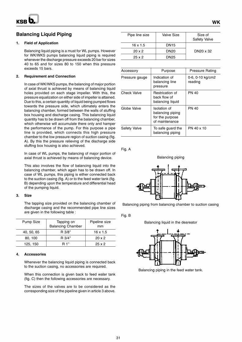
WK
Balancing Liquid Piping
1. Field of Application
Balancing liquid piping is a must for WL pumps. Howeverfor WK/WKS pumps balancing liquid piping is requiredwhenever the discharge pressure exceeds 20 bar for sizes40 to 65 and for sizes 80 to 150 when this pressureexceeds 15 bars.
2. Requirement and Connection
In case of WK/WKS pumps, the balancing of major portionof axial thrust is achieved by means of balancing liquidholes provided on each stage impeller. With this, thepressure equalization on either side of impeller is attained.Due to this, a certain quantity of liquid being pumped flowstowards the pressure side, which ultimately enters thebalancing chamber, formed between the walls of stuffingbox housing and discharge casing. This balancing liquidquantity has to be drawn off from the balancing chamber,which otherwise will accumulate there only and hamperthe performance of the pump. For this purpose a pipeline is provided, which connects this high pressurechamber to the low pressure region of suction casing (fig.A). By this the pressure relieving of the discharge sidestuffing box housing is also achieved.
In case of WL pumps, the balancing of major portion ofaxial thrust is achieved by means of balancing device.
This also involves the flow of balancing liquid into thebalancing chamber, which again has to be drawn off. Incase of WL pumps, this piping is either connected backto the suction casing (fig. A) or to the feed water tank (fig.B) depending upon the temperature and differential headof the pumping liquid.
3. Size
The tapping size provided on the balancing chamber ofdischarge casing and the recommended pipe line sizesare given in the following table :
Pump Size Tapping on Pipeline sizeBalancing Chamber mm
40, 50, 65 R 3/8’’ 16 x 1.5
80, 100 R 3/4’’ 20 x 2
125, 150 R 1’’ 25 x 2
4. Accessories
Whenever the balancing liquid piping is connected backto the suction casing, no accessories are required.
When this connection is given back to feed water tank(fig. C) then the following accessories are necessary.
The sizes of the valves are to be considered as thecorresponding size of the pipeline given in article 3 above.
Pipe line size Valve Size Size ofSafety Valve
16 x 1.5 DN15
20 x 2 DN20 DN20 x 32
25 x 2 DN25
Accessory Purpose Pressure Rating
Pressure gauge Indication of 0-6, 0-10 kg/cm2balancing line readingpressure
Check Valve Restrication of PN 40back flow ofbalancing liquid
Globe Valve Isolation of PN 40balancing pipingfor the purposeof maintenance
Safety Valve To safe guard the PN 40 x 10balancing piping
Fig. A
Balancing piping
Balancing piping from balancing chamber to suction casing
Fig. B
Balancing liquid in the deareator
Balancing piping in the feed water tank.
31

WK
5. Illustrations
i) Balancing liquid fed back to suction casing. Fig. A
ii) Balancing liquid fed back to feed water tank. Fig. B
iii) Arrangement of valves in balancing line. Fig. C
6. Precautionary Notes
i) Connection of balancing liquid piping whether tosuction casing or to the feed water tank is indicatedon the front page (Technical Data Sheet) of the orderacceptance. This is to be strictly adhered to.
ii) Size of the balancing liquid piping should be exactlyas given in article 3 above.
iii) Whenever the balancing liquid line is fed back tofeed water tank, and if more than one pumps areoperating in parallel, the individual balancing liquidlines should be independently connected to the feedwater tank, without joining them together, or evenputting them into a common header.
iv) The globe valve in the balancing liquid line back tofeed water tank should always remain in fully opencondition, and on no account should it be closed evenby accident.
v) The piping for safety valve has to be branched priorto the check valve, so that all the further piping issafe guarded against the increase in pressure.
Feed water tank
Globe valve
Check valve
Pressure Gauge
Z = End of KSB Supply
Safety valve
Fig. C
32

WK
NOTES

WK
NOTES

WK
NOTES

WK

Operating Instructions WK
Manufactured in technical collaboration with KSB Aktiengesellschaft., Germany by :
PUMPS LIMITEDWorks : Telephone No. TelefaxPimpri - Irrigation and Process Division, (020) 772008, 770990 (020) 776120
Mumbai-Pune Road, Pune - 411 018Chinchwad - Power Projects Division,
D-II Block, MIDC, Pune - 411 019 (020) 773882, 774213, 774389 (020) 770890Coimbatore - Water Pumps & Valves Division, NSN Palayam Post, (0422) 892547 - 9, 892647 (0422) 892650
151, Mettupalayam Road - 641 031Vambori - Foundry Division, Ahmednagar - 413 704 (02426) 72528, 34, 50 (02426) 72443Sinnar - Water Pumps Division, (02551) 30252, 53, 30255, 30256 (02551) 30254
Plot No. E - 3, MIDC Sinnar, Malegaon, Dist. Nashik - 422 103
Regd. Office :Mumbai - 126, Maker Chamber III, Nariman Point - 400 021 (022) 2854237 - 42 (022) 2873299
Zonal Offices :
Mumbai - 126, Maker Chamber III, Nariman Point - 400 021 (022) 2854237 - 42 (022) 2873299Calcutta - 30, Circus Avenue, 2nd Floor, 700 017 (033) 2470473, 2400117 - 8 (033) 2470588NOIDA - KSB House, A-96, Sector IV, NOIDA (0118) 54091 - 93 (0118) 525627, 550567
Dist. Gautam Budh Nagar, 201 301Chennai - Guindy House, 2nd Floor, 95 Anna Salai, 600 032 (044) 2352571 - 2, 2300629 (044) 2352749
Branch Offices :
! Ahmedabad - (079) 7540428, 7543427 ! Aurangabad - (0240) 351440 ! Bangalore - (080) 3491806, 3493925 ! Baroda - (0265) 330532, 333226 ! Bareilly - (0581) 452748! Bhubaneshwar - (0674) 557031 ! Chandigarh - (0172) 544685, 549021 ! Durgapur - (0343) 545539 ! Guwahati - (0361) 569689 ! Hubli - (0836) 251057! Indore - (0731) 529478, 529704 ! Jaipur - (0141) 384121, 381206 ! Jamshedpur - (0657) 433461, 433471 ! Kochi - (0484) 394667 ! Lucknow - (0522) 213492, 274492! Nagpur - (0712) 535062 ! Pune - (020) 5536345, 5536347 ! Raipur - (0771) 426708 ! Secunderabad - (040) 7017696 ! Vijayawada - (0866) 433796, 433384
Service Stations :Odhav - Shed 22, G.V.M. Estate, Amedabad 382 410 (079) 2870372NOIDA - A - 96, Sector IV, 201 301 (0118) 91 - 525626, 550567Howrah - 142, Foreshore Road, Ramkrishnapur (033) 6602909
Tech
nica
l mat
ter
subj
ect t
o ch
ange
with
out n
otic
e.

Works Order No. : ________________________________________________
Pump Type & Size : ________________________________________________
Operating Instructions0011.81 / 00 - 18 G3 WK
High Pressure Centrifugal Pumps
These operating instructions contain fundamentalinformation and precautionary notes. Please read themanual thoroughly prior to installation of unit, electrical
connection and commissioning.It is imperative to comply with all other operating instructionsreferring to components of individuals units.