wl roof series - ks-kentico-prod-cdn-endpoint.azureedge.net
TRANSCRIPT

DISCLAIMER: THE DETAILS ARE PROVIDED AS A GUIDELINE FOR PROPER PANEL AND ASSOCIATED COMPONENT DESIGN, AND ARE BASED ON INDUSTRY ACCEPTED PRACTICES.
PANEL SPANS, CLIP SPACING AND FASTENER RECOMMENDATIONS ARE PROJECT SPECIFIC AND SHOULD BE DETERMINED BY THE ENGINEER OF RECORD. FOR SIMPLICITY ALL
DETAILS CONTAINED HEREIN SHOW 2 FASTENERS PER CLIP (MINIMUM REQUIREMENT).
INSULATION, PURLINS/JOISTS, DECKING, MISCELLANEOUS STRUCTURAL SUPPORTS ETC. ARE SHOWN FOR CLARITY ONLY, AND ARE NOT SUPPLIED BY MORIN (N.B.M.).
FOR PROJECT SPECIFIC ENGINEERING AND DESIGN ASSISTANCE, AS WELL AS INFORMATION ON RADIUS PANEL OPTIONS, PLEASE CONTACT MORIN TECHNICAL SERVICES.
I
Introduction............................................................................................................................1
Warranties, Installation, Material Specifications
Basic Installation Tool List....................................................................................................2
Field Metal Cutting Tool List...................................................................................................3
Pre- Installation Check List.....................................................................................................4
Design Data...........................................................................................................................5
Slope, Thermal Movement, Gauge Selection, Corrosion Resistance,
Deflection, Fabrication Tolerances, Walking Loads
Technical Data......................................................................................................................9
Uplift Chart, Physical Data, Structural, Temperature, Diaphragm,
Test Ratings
Fastening Guidelines..........................................................................................................11
Clip Selection/Location, Load Calculations, Flashing, Trim,
Fasteners, Sealants
Panel Installation................................................................................................................12
Panel Clip & Accessories.....................................................................................................19
Testing..................................................................................................................................22
Typical Roof Condition Layout and Details Index...............................................................23
MCA Technical Bulletin 1040 ........................................................................................67
Lightning and Metal Roofing
MCA Technical Bulletin 1050 ........................................................................................69
Metal Roof Coating Maintenance
MCA Technical Bulletin 1060 ........................................................................................71
Oil Canning
MANUAL DOES NOT APPLY TO ZINC OR COPPER APPLICATIONS
REV 11/18
SWL Roof Series
MORINCORP.COM * BRISTOL, CT * FONTANA, CA * DELAND, FL * T: 800-640-9501

SWL Roof Series manual is an introduction to Morin’s recommendations. While some of these recommendations
may or may not be agreed to by all, it must be remembered that these are the methods that Morin recommends
and/or requires to activate the warranties to our material upon completion of a project.
It is generally understood that one of the most serious problems with metal roofing in the past has been leaking,
because of the use of thru-fastening to the substrate. Using this method, holes are drilled through the panels
and then fasteners are installed through these holes for attachment to a structural substrate. In time, these holes
will elongate due to thermal expansion/contraction, which in turn will cause the panel to leak. The standing seam
roof panel system eliminates this problem by using the factory or field roll formed panels that are attached to the
structural substrate by the use of concealed sliding clips. Morin's SWL Roof Series clips are fixed and the panels
move up and down the slope engaging on the clips rather than the clips sliding and running out of expansion
capacity. The SWL Roof Series systems (i.e. panels, closures, clips) can be designed into a low
slope, (> 1/2” in 12") leak free system for use in roofing and walls on both new and retrofit construction. The
SWL Roof Series panels can be curved to various radiuses.
Please contact your local representative for further information. Several ancillary systems (i.e. gutters,
downspouts, ridge ventilators, fascias, window and rake end trim) are not standard, but are fabricated for
specific job requirements. Our suggested details for these conditions are included in the following sections of this
manual.
WARRANTIES:
Morin can furnish the various extended performance warranties as required by a project’s specification. The
items covered by this warranty are standard and include such items as weather-tightness, structural performance
and finish performance. Contact your local representative for a sample copy of these warranties. The above
warranties cover only the materials furnished by Morin and will not become valid until all remittance is complete.
Furthermore, if requesting a weather-tightness warranty, a complete set of shop drawings and specifications are
required for review prior to installation. Three jobsite inspections are also required. The effective date of the
warranty will be the date of the substantial completion of work, but no later than nine (9) months after material
has shipped from a Morin plant.
INSTALLATION:
Morin recommends that our SWL Roof Series panel should be installed under the direct supervision of an
experienced sheet metal craftsman, trained in the proper application of the system.
MATERIAL SPECIFICATIONS:
The SWL Roof Series panel is supplied in standard widths of 12”, 16”, and 18” and the standard material
thickness is 24 through 18 gauge for steel, as well as 0.032”, 0.040”, and 0.050” for aluminum. All panels are
supplied with either a non-coated mill finish or with a prefinished coating using standard 1.0 mil Fluorocarbons
and High Build Fluorocarbons, depending on the project’s performance requirements. Standard panel fabrication
lengths are available from 5' (1.52m) up to 30’ (9.14m). Longer lengths of panel are available however not
recommended due to handling restrictions.
COOL METAL ROOFING AND LEED
®
:
Morin’s SWL Roof Series meets the requirements of these programs. Contact your local representative for
additional information.
1
INTRODUCTION:
SWL Roof Series
MORINCORP.COM * BRISTOL, CT * FONTANA, CA * DELAND, FL * T: 800-640-9501

2
BASIC INSTALLATION TOOL LIST:
· Measuring Tape
· Pencil
· Offset. Straight and Left Cut. Red Grip Snaps
· Offset. Straight and Right Cut. Green Grip Snaps
· Hand Seamers
· Utility Knife and Blades
· 6" Vise-Grip Locking C-Clamps
· Pop Rivet Tool
· 6" Speed Square
· Tool Belt
· 1
1
2
" Wood Chisel
· Hammer. Straight Claw 16 oz.
ADDITIONAL TOOLS TO SPEEDUP INSTALLATION:
· Duckbill. Vise-Grip. Locking Sheet Metal Tool
· 12" Speed Square
· Construction Master, Contractor's Calculator
· Roper Whitney No. 5 Jr. Punch Kit
· Hand Crimper
· Bend Moore. Hemming Tool
Can be purchased at most:
Lowes, Home Depot, Granger, Dynamic Fastener, Triangle Fastener, Ram Tool, and Fastenal
SWL Roof Series
MORINCORP.COM * BRISTOL, CT * FONTANA, CA * DELAND, FL * T: 800-640-9501

3
FIELD METAL CUTTING TOOL LIST:
· Metal Cutting Circular Saw
· Tenryu Steel-Pro Saw Blade for Circular Saw
· Nibbler
· Porta - Band. Bandsaw
· Sawzall. Reciprocating Saw
· Kett Shears
· Swanson Shear
Can be purchased at:
Granger, Dynamic Fastener, Triangle Fastener, Ram Tool, and Fastenal
SWL Roof Series
MORINCORP.COM * BRISTOL, CT * FONTANA, CA * DELAND, FL * T: 800-640-9501

4
PRE - INSTALLATION CHECK LIST:
• Review contract documents and approved shop drawings prior to installation to verify that they
match the structure.
• Examine the structure for alignment prior to installation. Verify that all surfaces are
flat, plumb, level, straight, square, and within panel tolerances of ¼” in 20 feet.
Any variance from tolerances can affect panel performance, aesthetics, and installation and must
be reported to the general contractor, and corrected by the responsible party before panel
installation begins.
• Set benchmarks for panels and trim per contract documents and approved shop drawings. This
will ensure better panel alignment, easier panel installation, panel performance, and aesthetics for
the project.
• Verify that all blocking, supports, and penetrations are in place before installation begins.
• Verify clip placement and fastening points based on project specific shop drawings and
calculations.
• Verify that staged panels match the shop drawings based on specific elevation.
• Verify that panels and trim are clean and free of damage. Do not install any damaged materials.
• Verify that the installer has the proper tools for panel and trim installation.
• Verify that all equipment, safety gear, and procedures meet and/or exceed the OSHA approved
standards.
NOTE: Ensure that all conditions on the Pre-Installation Checklist are met prior to the installation of
panels. If any one of these conditions are not met, MORIN recommends that installation of panels not
begin until the issue is rectified.
SWL Roof Series
MORINCORP.COM * BRISTOL, CT * FONTANA, CA * DELAND, FL * T: 800-640-9501
5
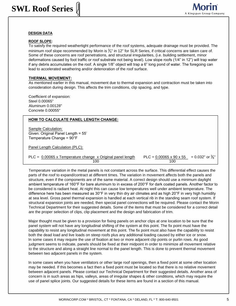
ROOF SLOPE:
To satisfy the required weathertight performance of the roof systems, adequate drainage must be provided. The
minimum roof slope recommended by Morin is
3
4
" in 12" for SLR Series, if critical concerns are taken care of.
Some of these concerns are roof penetrations, and structural irregularities, (i.e. building settlement, minor
deformations caused by foot traffic or roof substrate not being level). Low slope roofs (1/4” in 12”) will trap water
if any debris accumulates on the roof. A single 1/8” object will trap a 6” long pond of water. The foregoing can
lead to accelerated weathering and/or deterioration of the roof surface.
THERMAL MOVEMENT:
As mentioned earlier in this manual, movement due to thermal expansion and contraction must be taken into
consideration during design. This affects the trim conditions, clip spacing, and type.
Coefficient of expansion:
Steel 0.00065"
Aluminum 0.00128"
Concrete 0.00055"
HOW TO CALCULATE PANEL LENGTH CHANGE:
Sample Calculation:
Given: Original Panel Length = 55’
Temperature Change = 90°F
Panel Length Calculation (PLC):
PLC = 0.00065 x Temperature change x Original panel length PLC = 0.00065 x 90 x 55 = 0.032" or
3
8
"
100 100
Temperature variation in the metal panels is not constant across the surface. This differential effect causes the
parts of the roof to expand/contract at different times. The variation in movement affects both the panels and
structure, even if the components are of the same material. A correct design should use a minimum daylight
ambient temperature of 160°F for bare aluminum to in excess of 200°F for dark coated panels. Another factor to
be considered is radiant heat. At night this can cause low temperatures well under ambient temperature. The
difference here has been measured as 30°F in very thin dry air climates and as high 20°F in very high humidity
at sea level. Gross panel thermal expansion is handled at each vertical rib in the standing seam roof system. If
structural expansion joints are needed, then special panel connections will be required. Please contact the Morin
Technical Department for their suggested details. Some of the items that must be considered for a correct detail
are the proper selection of clips, clip placement and the design and fabrication of trim.
Major thought must be given to a provision for fixing panels on anchor clips at one location to be sure that the
panel system will not have any longitudinal shifting of the system at this point. The fix point must have the
capability to resist any longitudinal movement at this point. The fix point must also have the capability to resist
both the dead load and live loads on steep roofs plus any additional loading caused by either ice or snow.
In some cases it may require the use of fixation at two or more adjacent clip points or purlin rows. As good
judgment seems to indicate, panels should be fixed at their midpoint in order to minimize all movement relative
to the structure and along a straight line normal to the panel length. This is done to prevent thermal movement
between two adjacent panels in the system.
In some cases when you have ventilators or other large roof openings, then a fixed point at some other location
may be needed. If this becomes a fact then a fixed point must be located so that there is no relative movement
between adjacent panels. Please contact our Technical Department for their suggested details. Another area of
concern is in such areas as hips, valleys, areas of irregular shapes & other conditions, which may require the
use of panel splice joints. Our suggested details for these items are found in a section of this manual.
DESIGN DATA
SWL Roof Series
MORINCORP.COM * BRISTOL, CT * FONTANA, CA * DELAND, FL * T: 800-640-9501

6
In addition to the above, a designer must also give some thought concerning such accessory items as gutters,
downspouts, ridge caps, gable trim or related flashing. All of these trim items must be designed and fastened to
adequately account for their expected thermal movement.
Everything mentioned above applies to both steel and aluminum. With aluminum this is very critical, in as much as
it’s coefficient of expansion is twice that of steel. In either case, steel or aluminum, trim lengths should not
exceed 20’ in order to try to eliminate the elongation of fastener holes, oilcans or kinks. Flashing lap joints must be
allowed to move. Screws or rivets should not be used to hold flashing lengths together. Several types of joinery that
allow for thermal movement are shown in our detail section found in this manual.In areas where it is not feasible to
furnish full length (ridge/eave) factory fabricated panels because of either shipping limitations or adding to the
length of existing roof panels, it will be required to use a panel splice lap joint.
For weather resistance, these are designed to be sealed joints with structural fixpoint connections that prevent
relative movement between adjacent panels. The reason for this is that any movement may over stress the sealant
and cause a leak or cause fastener holes to elongate with the same leak results.
PANEL GAUGE SELECTION:
Some of the items that must be considered when selecting the minimum gauge of a standing seam roof panel are
material types, panel width and panel rib height. Economy in gauge selection may be had if the lightest gauge
available meets the performance requirements of the project. If this is found to be the case, then structural standing
seam roof panel systems can be fabricated in heavier gauges or purlin spacing can be designed to allow for the
maximum span of the standing seam roof panel system selected. Sometimes economies of gauge purlins can
outweigh the cost savings of using the standing seam roof panel systems maximum spans. These components
should be taken into account in order to receive the best overall cost for the project.
PANEL SUBSTRATE DETERIORATION:
In the metal panel industry, deterioration is generally known to be “corrosion”. Corrosion is nothing more than metal
oxidation, (i.e. red rust/steel or white rust/aluminum). In order to fight this problem, it is recommended that only
stainless steel or metal coated/plated fasteners or clips be used in the standing seam roof panel system. The
reason for this is that there is the possibility of water condensation at the base of the fastener, which could
accelerate fastener deterioration. All fasteners must be compatible with the panel substrate in order to allow the
building envelope to have a long performance in the project’s atmospheric environment.
DEFLECTION:
Building codes in most cases do not set limits on the deflection of roof cladding; therefore this item is overlooked in
the design of standing seam roof panel systems. Usually these codes limit the deflection to structural members
only if other materials supported are sensitive to great movement and/or cracking. Deflection should be calculated
if there is concern for drainage or the possibility of a clearance problem with secondary structural members. The
Southern Building Code and BOCA limit deflection to L/180 while the Aluminum Association sets the limit at L/60.
However, the designer should always check the local codes for the limits that they should set and these limits
should be included in the project specifications. Uniform loading changes the standing seam roof products section
properties as the panel distorts, (i.e. panels become more rigid under positive loads and more flexible under
negative loads). To determine the actual allowable negative load ability of a standing seam roof panel system a
full-scale wind uplift test should be run. From these tests, a negative load table with appropriate safety factors can
be developed.
Positive load capacity can be calculated using the products section properties and in accordance with AISI
Specifications. The flat of the standing seam roof panel, at its intersection with its vertical rib, when put under a
positive or negative load, will deflect. In checking clearances, both positive and negative clearances must be
determined.
DESIGN DATA
SWL Roof Series
MORINCORP.COM * BRISTOL, CT * FONTANA, CA * DELAND, FL * T: 800-640-9501

7
FABRICATION TOLERANCE:
The Metal Construction Association (MCA) has developed tolerances for acceptable manufacturing practices.
These tolerances are now considered to be the metal panel industry standard and are published in the MCA
Manual. The following is a brief summary of these tolerances:
Panel Length + / – 3/8”
Panel End Squareness
Viewed from Panel Front 0.5% of width or
measured across sheet no more than 1/8” at one end
Viewed from Panel Side 2.0% of panel
measured across sheet depth or no
more than 1/16”
Camber 3/16” per 10’ length
(lateral bow of panel viewed
from panel front)
Squareness should be measured using the panel "diagonal difference" method. Generally both ends will
be parallel so 1/8" out of square at an end can correspond to 1/4 inch diagonal difference. Squareness thus
determined is a function of panel length and width.
If the tabulated level of camber renders a particular product unserviceable for reasons other than aesthetics,
it shall not be acceptable.
Other "as fabricated" profile dimensional tolerances (e.g. cover width and sub-element lengths, radii and angular
tolerances) can be somewhat meaningless. These dimensions are difficult to consistently measure and the
profiles are difficult to sustain during transit and installation. Sometimes profile must be field adjusted for in place
aesthetics. The final "in place" condition is the essential factor.
DESIGN DATA
SWL Roof Series
MORINCORP.COM * BRISTOL, CT * FONTANA, CA * DELAND, FL * T: 800-640-9501
PANEL END SQUARENESS
Viewed from panel front
measured across sheet
.
3
8
"
Tolerance
PANEL LENGTH
Viewed from panel side
measured across sheet
CAMBER
1
0
'
-
0
"
T
o
le
r
a
n
c
e
8
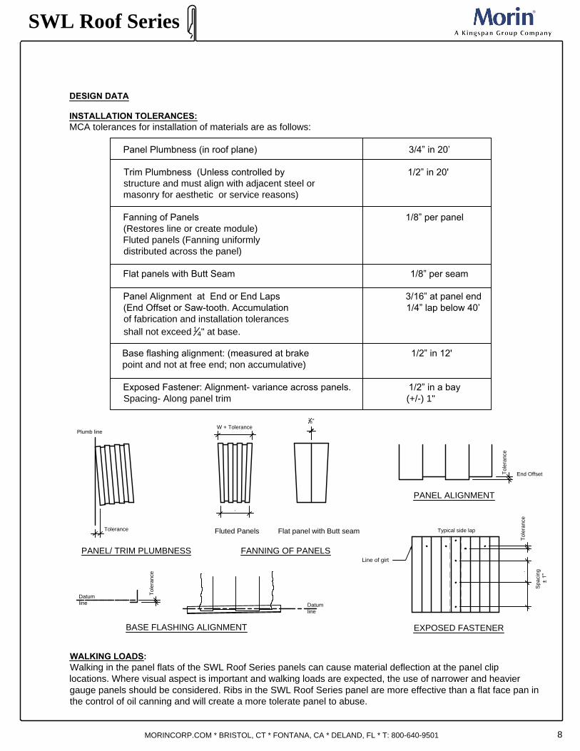
INSTALLATION TOLERANCES:
MCA tolerances for installation of materials are as follows:
Panel Plumbness (in roof plane) 3/4” in 20’
Trim Plumbness (Unless controlled by 1/2” in 20'
structure and must align with adjacent steel or
masonry for aesthetic or service reasons)
Fanning of Panels 1/8” per panel
(Restores line or create module)
Fluted panels (Fanning uniformly
distributed across the panel)
Flat panels with Butt Seam 1/8” per seam
Panel Alignment at End or End Laps 3/16” at panel end
(End Offset or Saw-tooth. Accumulation 1/4” lap below 40’
of fabrication and installation tolerances
shall not exceed
1
4
" at base.
Base flashing alignment: (measured at brake 1/2” in 12'
point and not at free end; non accumulative)
Exposed Fastener: Alignment- variance across panels. 1/2” in a bay
Spacing- Along panel trim (+/-) 1"
WALKING LOADS:
Walking in the panel flats of the SWL Roof Series panels can cause material deflection at the panel clip
locations. Where visual aspect is important and walking loads are expected, the use of narrower and heavier
gauge panels should be considered. Ribs in the SWL Roof Series panel are more effective than a flat face pan in
the control of oil canning and will create a more tolerate panel to abuse.
DESIGN DATA
Tolerance
Plumb line
W + Tolerance
.
1
8
"
PANEL/ TRIM PLUMBNESS FANNING OF PANELS
Flat panel with Butt seamFluted Panels
Tolerance
End Offset
PANEL ALIGNMENT
Datum
line
Datum
line
Tolerance
Tolerance
Spacing
± 1"
.
Typical side lap
Line of girt
BASE FLASHING ALIGNMENTEXPOSED FASTENER
SWL Roof Series
MORINCORP.COM * BRISTOL, CT * FONTANA, CA * DELAND, FL * T: 800-640-9501

9
PRODUCT SUMMARY:
SWL Roof Series, a structural standing seam
roofing panel system. Options for architects include
three panel widths and different rib options.
PRODUCTION REFERENCES:
Lengths 5' (1.52m) to 30' (9.14m) Standard
Longer lengths available (not recommended due to
handling restrictions)
Jobsite roll forming in lengths up to 300'
STORAGE AND INSTALLATION NOTES:
Deliver panel materials and components in the original,
unopened, undamaged packaging with identification
labels intact.
Store roof materials on dry, firm, and clean surface.
Elevate one end of bundle to allow moisture runoff,
cover and ventilate to allow air to circulate and
moisture to escape.
Install panels plumb, level, and true-to-line to
dimensions and layout indicated on approved shop
drawings.
Remove protective film immediately as per standard
directions.
Cutting and fitting of panels shall be neat, square and
true. Torch or abrasive cutting is prohibited.
PRODUCT OFFERINGS:
Panel Type - Structural standing seam roof panel
Minimum Roof Slope: 2:12
Panel Depths - 1
3
4
"
Cover Widths - 12" (305mm) or 16" (406mm) or
18" (457mm)
MATERIAL OPTIONS:
Painted Steel: Galvalume/Zincalume 18GA (1.19mm),
20GA (.91mm), 22GA (.76mm), 24GA (.60mm)
Stainless Steel: 20GA, 22GA and 24 GA
Aluminum: 0.050GA (1.27mm), 0.040GA (1mm) and
0.032GA (.81mm)
COLOR AND FINISH OPTIONS FOR ALUMINUM AND STEEL:
Standard (Fluropon
®
PVDF-Kynar500
®
)
Premium Colors MICA (Fluropon Classic
®
II PVDF)
Premium Colors METALLIC (Fluropon Classic
®
PVDF)
Morin Custom Color Matching Services
Other Finishes Available
Surface Options- Smooth surface standard, stucco embossed
texture optional.
Sealant- Optional factory caulk available.
Clip- SWL Clip
Substrate- Open framing or solid decking application.
·
· ·
·
·
·
SWL Roof Series
MORINCORP.COM * BRISTOL, CT * FONTANA, CA * DELAND, FL * T: 800-640-9501
FINISH SIDE
FINISH SIDE
12"
FINISH SIDE
16"
FINISH SIDE
FINISH SIDE
FINISH SIDE
18"
FINISH SIDE
FINISH SIDE
FINISH SIDE
12" 16" 18"
16" 18"
TECHNICAL DATA
1
3
4
"
1
3
4
"
1
3
4
"
1
3
4
"
1
3
4
"
1
3
4
"
1
3
4
"
1
3
4
"
SWL-12-0
SWL-12-1
SWL-12-2
SWL-16-0
SWL-16-1
SWL-16-2
SWL-18-0
SWL-18-1
SWL-18-2
PANEL PROFILES AVAILABLE:
12"
1
3
4
"

10
.
SWL Roof Series
MORINCORP.COM * BRISTOL, CT * FONTANA, CA * DELAND, FL * T: 800-640-9501
STRUCTURAL – UPLIFT LOADS:
The SWL Series panel systems uplift capacities are based on the requirements of ASTM E1592,
UL580. Actual uplift loads are determined by an independently certified load test of production run panels. ASCE
7 is the basis of use with most major code bodies that specifies that higher uplift pressures be used at the
perimeters and thus the SWL clips must be spaced closer together to allow for the increased uplift pressures
when compared to the general field of the roof. This means that if an open purlin design is used, then the purlin
spacing at the perimeter must be shortened to allow for the smaller spans required by the SWL Series system.
Determination of the required wind uplift pressure (psf) for all roof loading areas must be provided in the
specifications and/or drawings by the architect and/or engineer of record. This information is needed in order to
make the correct panel selection and clip spacing during the bidding process. Also carefully review the submittal
to verify that the fasteners that secure the SWL clip to the structure are adequate to resist the uplift loads
mentioned above.
THERMAL LOADS – PRESSURE PARALLEL TO THE ROOF:
Structural supports are exposed not only to wind or snow loads, but also to expansion and contraction thermal
loads due to temperature induced friction forces at the anchor points. Generally speaking these forces can be
ignored, but in some cases they can build up quite rapidly and become very noticeable. They should be
definitely checked when single panel lengths exceed 180’. A basic assumption is that a friction induced forced is
additive, allowing a 20 pound per clip friction allowance is then conservative based on the “stick/slip” movement
of the panel in relation to the clip. It is highly unlikely all clip resistance is at the same place at the same
time. “Fixed points” in the SymmeTry system may require lateral support, similar to that used in a structural wind
truss design, due to these thermal loads.
PANEL SYSTEM DIAPHRAGM STRENGTH:
The SWL Series system is a floating system and therefore has no effective diaphragm strength. Therefore the
roof structure must be designed with wind bracing.
UNDERWRITERS (UL) ROOF APPROVAL:
In most building locations it will be found that they will require that some form of Underwriters Classification must
be in place to help reduce the cost of insurance. The SWL system carries a UL-90 class rating. Consult our
technical department or Underwriter’s Building Directory for the requirements of the listed construction. Morin’s
SymmeTry Series systems are listed under UL Design Nos.
FIRE RATINGS:
Morin’s roof systems are fabricated from either steel or aluminum. These materials are generally considered by
most code bodies and fire jurisdictions to qualify as fire retardant roof coverings. Because of this they may be
used with other materials to satisfy a requirement for an hourly rated system to meet a specific fire protection
need. Contact our technical department for various rates up to 4 hours. UL rates the roof systems in either steel
or aluminum as a Class A Roof Covering for use over purlins or non-combustible decks.
AIR AND WATER INFILTRATION:
Air and Water Infiltration testing has been conducted on the SWL Series panel system in accordance with ASTM
E283 and ASTM E 331, 1680 and 1646.
CYCLE WEAR TEST:
The SWL Series system has been tested over 1,000,000 cycles of expansion/contraction in both steel and
aluminum and with both internal and hook clips. Panels or clips did not wear through; these tests indicate that
the system will exceed the 20-year life cycle of the roof.
TECHNICAL DATA

11
SWL Roof Series
MORINCORP.COM * BRISTOL, CT * FONTANA, CA * DELAND, FL * T: 800-640-9501
SWL SERIES CLIP SELECTION:
Clip selection is a relatively simple task once you have collected all of the data required. This data includes such
items as type of structure, all structural loading, thermal expansion/contraction needs and even sometimes the
finished appearance that the designer is looking for on a particular project. After making the final clip selection,
the designer should make sure that the structural supports are supplied with the correct size, spacing and
clearance to accommodate the clip selected. From clip sketches shown in this manual, the clearance between
the panels and supporting purlin or deck is
3
8
".
SWL SERIES CLIP LOCATION:
Clips are to be spaced at the maximum spacing as shown on the calculations submitted to the architect at the
time the contractors make their material submittal, but must not exceed the maximum spacing as shown in the
manufacturers literature for the required loads. When the roof system is used over a solid substrate (deck), the
spacing of the clips must be examined to be sure that this spacing does not exceed the spacing of the panel/clip
system but also does not exceed the strength of the fastener, which connects the clip to the substrate.
FASTENER LOAD CALCULATIONS:
To calculate the wind uplift loads for any fastener or fastener group, you must take the following items into
account:
· Design wind load uplift.
· Tributary area of fastener.
· Fastener manufacturer’s information as to the pullout/pullover of the fastener being considered.
· The local building code safety factor requirements.
· As mentioned earlier in this manual, you should also check the loads that snow and expansion/contraction
places on the fastener to be sure that those loads do not exceed the fastener manufacturer’s
recommendations.
FLASHING, TRIM & MISCELLANEOUS FASTENERS:
While SWL Series panels & clips are the primary concern when using the Morin roofing system, you should not
overlook the importance of flashing & their fasteners. After all, a leak at this location is just as bad as a leak
through the roof panel. If at all possible, these fasteners should not be installed in a manner that would penetrate
the SWL panel. The fastener must be of a self sealing type with a sealing washer under its head on the exposed
surface. Pop rivets should never be used with flashing or trim because they will leak. If it is found that there is no
other solution to fastening flashings, then be sure that closed end rivets are used and that they are both plugged
and sealed. The minimum size fastener to be used to connect flashing and trim to the standing seam panel
should be either a #10 screw or
1
8
" rivet.
SEALANTS:
The roof system is designed & manufactured to give 20 years of service. Because of this, it is our
recommendation that the sealants specified or used have an equal life expectancy. In applying sealants to a
metal surface, one of the most important aspects for a good seal is to have a clean and dry surface and that the
sealant being used is applied in accordance with the manufacturers recommendations. There are two types of
joints on which sealant is required. They are exposed and non-exposed joints. An exposed sealant joint should
use a sealant that will have a final cure that will stay flexible. Do not use either asphalt or oil base type sealant.
For non-exposed sealant joints, use only non-hardening type sealant, recommended by a sealant manufacturer.
There are several installers that prefer to use a silicone type sealant. This type of material will work fine as long
as it has the 20-yr service life expectancy. One word of caution when using this product is that you must be sure
that it is a non-acetic acid cure.
FASTENING GUIDELINE

12
SWL Roof Series
MORINCORP.COM * BRISTOL, CT * FONTANA, CA * DELAND, FL * T: 800-640-9501
PANEL INSTALLATION
1. COORDINATING THE INSTALLATION OF PANELS WITH OTHER TRADES
Careful attention prior to and during panel installation must be paid to the other trades working on the same project
as your roof installation. Failure to do so may result in compromised schedules and rising costs. For example, if
there is any new masonry and/or cement work on the same project, it should be scheduled prior to the roof panel
installation, so that the masonry/cement is complete and cured before any roof panels are installed. Trades involved
in electrical and HVAC may perform work in conjunction with the roof panel installation remembering to coordinate
the work such that those trades may perform their tasks while the roof is partially or completely installed. Keep in
mind too that some of the work performed by these trades may be detrimental to the roof structure and the materials
used are corrosive to metal roofs; such as copper, pressure treated wood, and HVAC cleaners.
2. INSPECT THE STRUCTURE
The area designated to receive the new roof panels must be inspected and conditions that fail to meet the
requirements of the roof system must be reported PRIOR to beginning the installation process.
a. Checking for Square - Failing to confirm that the structure and the roof system are square will have a major
impact on the success of the roof panel installation. Square and straight are not the same. Straightness reports on
any deviation along a single edge of an object, as in a straight line. Square is the correlation of one edge to
another edge. A square edge defines that the edges will be 90°, or perpendicular, to each other. If the measured
distance between diagonal roof corners is equal, then the installer will confirm the roof to be square.
b. The 3-4-5 Method - This method well known throughout the various construction trades helps the installer for
when the roof is not square. The goal is to install the metal panel so that it is square to the eave of the roof and
this technique will provide you with a reference line that is perpendicular (or square) to another edge, on any
surface of the roof. Required tools are: Tape measure; chalk line; hammer and two nails.
1. Step 1: Step 1: Starting at the bottom edge of the roof, measure a 6 inches off of the roof's edge (Figure
A), then draw a 3-foot horizontal line and set nails at each end. (Figure B)
2. Step 2: From the first nail set (on the left), pull a vertical 4-foot dimension and draw an arc. (Figure C)
3. Step 3: Measure from the second nail (on the right) exactly 5 feet diagonally up to the first arc and mark
the intersection from the 4-foot dimension (Figure D)
4. Step 4: Place the third nail. (Figure E)
5. Step 5: Mark a straight vertical line from the first nail to the third nail (Figure F) which will now show a
straight vertical line off the eave. This will give you a square reference line for your roof installation.
6. For larger right angles, use this same method for example in multiples of 3-4-5: 6-8-10, 9-12-15 etc.

13
RA
KE
E
DG
E
EAVE
RA
KE
E
DG
E
EAVE
3 Feet
4 F
eet
RA
KE
E
DG
E
EAVE
RA
KE
E
DG
E
EAVE
5
F
e
e
t
RA
KE
E
DG
E
EAVE
5
F
e
e
t
RA
KE
E
DG
E
EAVE
6"
FIGURE A
FIGURE B
FIGURE C FIGURE D
FIGURE E FIGURE F
SWL Roof Series
MORINCORP.COM * BRISTOL, CT * FONTANA, CA * DELAND, FL * T: 800-640-9501
PANEL INSTALLATION

14
c. In-plane alignment - While a roof may have been installed square, straight and flat, it may still not have
been installed correctly. The roof must be installed in-plane with the rest of the structure and other planes,
otherwise it will not appear right and performance may be compromised. When roof and wall surfaces are not
in-plane, it can sometimes be referred to as a “crooked” roof. In this scenario, even though each roof and wall
surface is straight, they are not straight to each other. Remember that misalignment may occur at the
intersection of different roof and transition sections. A misaligned or crooked roof will present with performance
issues, creating gaps and voids which will leak and weaken the roof.
ROOF
WALL
"In-Plane" alignment of roof and wall.
ROOF "B"
WALL
"In-Plane" alignment of all roof and wall sections.
ROOF "A"
ROOF
WALL
Incorrect Alignment of roof and wall
ROOF "B"
WALL
ROOF "A"
Incorrect Alignment of roof sections
SWL Roof Series
MORINCORP.COM * BRISTOL, CT * FONTANA, CA * DELAND, FL * T: 800-640-9501
PANEL INSTALLATION
15
SWL Roof Series
MORINCORP.COM * BRISTOL, CT * FONTANA, CA * DELAND, FL * T: 800-640-9501
PANEL INSTALLATION
3. FLATNESS
Straightness involves the edges of an object while flatness entails the wide, open surfaces of an object.
Installed roof panels must be both straight and flat. The issue of oil-canning on a metal roof is directly related to
panel surfaces which are not flat. When other roof structure members are out of alignment, the roof panels will
not lay flat. Some examples of this are:
- Decking is not flat due to warped panels or misaligned seams.
- Purlins, roof joists, and supporting members are twisted, warped, or “pre-stressed”.
a. Pre-Cambered Roof Members - When using pre-cambered traditional roof support members with metal
roofing systems, they may fail to flatten out due to the light weight of the metal roof material as compared to more
traditional roofing materials. When pre-cambered structural members are installed prior to the installation of a
metal roofing system, and it is noted after the metal roof installation, that there is a loss of flatness in the metal
panels, the condition should be brought immediately to the attention of appropriate authorities, as these causes
are not the installer's fault and out of their control.
b. Water and Flatness - While flatness will not cause a panel to leak, a panel that is not Installed flat can
create an area of standing water or result in direct runoff to areas were not intended to handle the additional
water.
4. ESTABLISHING DIRECTION AND SEQUENCE OF INSTALLATION
Many factors play a major role in establishing the direction and sequence of the panel installation. For example
geographic factors such as prevailing wind direction; roof design factors such as panel types, seams and profiles;
structural characteristics including building length and width. A major determination is the direction of the
installation as this will directly impact exactly where the installation will start, which in turns directly impacts how
and where materials are distributed on the ground or pre-loaded onto the roof structure.
a. Prevailing Winds - Starting at the lower corner of the roof edge, install the panels vertically and downwind
or away from the prevailing wind. The work is performed in this manner so that the wind, rain or snow blows over
and not under the side lap seam joints.
b. Panel Layout - There are times when the metal roof panel's seam and profile will determine the direction of
the installation, i.e. left-to-right or vice versa. Also some metal roof panels have applied coatings that require
them to be installed in the same way directionally. Taking the time to properly plan the panel layout will save you
and your client time, material and labor and deliver on an aesthetically pleasing and high performing roof.
c. Single Panel Eave-To-Ridge - When the roof design calls for a single, eave-to-ridge length panel
dimensional tolerances must be adhered to by the installer, as well as panel straightness and flatness tolerances.
d. Multiple Panels Eave-To-Ridge - For when the roof design calls for multiple panels, factors in addition to
dimensional tolerances must be maintained. Most important is the alignment of the lapped panels to avoid “Dog
Legs” of the installed panels.

16
.℄
2. Place edge of first panel on center line of run.
2
1
SWL Roof Series
MORINCORP.COM * BRISTOL, CT * FONTANA, CA * DELAND, FL * T: 800-640-9501
PANEL INSTALLATION
5. SUSTAINING PANEL MODULARITY AND ALIGNMENT
The relationship of the installed roof panel to other installed roof panels, roof structure members and the structure
that the roof rests upon is called panel modularity. Modularity affects the strength, performance and aesthetics
factors of the finished roof.
a. Starting Square To The Eave - The technique of starting the first panel “square to the eave” will establish a
baseline and reference for the remainder of the panels, and impact the appearance and performance of the
finalized roof.
b. Monitor and Measure During Installation - The measurement and monitoring of the roof, its members and
conditions during the installation are the responsibility of the installer. Once a square edge has been determined
and established as the reference, all distances must be measured from and compared to that square
edge/reference in order to effectively monitor and maintain squareness, never forgetting that small errors grow
over distance.
c. Sawtoothing at Eave, End Laps and Ridge - Sawtoothing of the panels will occur when the roof panels are
not installed square to the roof edge or eave. To avoid or reduce this risk the installer should always make sure
that the first panel installed is square to the corresponding roof edge and aligned to panels at other tiers. (See 2b.
The 3-4-5 Method)
d. Alignment and Aesthetic Considerations -Keep in mind that some people are of the opinion that the
finished appearance of the newly installed metal roof is just as important as the performance of that same metal
roof. Proper planning before the actual installation will deliver an installed roof that meets visual and performance
requirements. Remember to always create benchmarks, i.e. the straight vertical lines as previously noted. There
are two accepted methods to achieve a balanced, proportioned installation. Either locate the seam at the center
line of the roof or locate the center line of the panel on the center line of the roof.
The panels are installed beginning at the center of the run and working towards either the right or left end of the
run. This procedure ensures that the panel seams are symmetrical about the center line of the run.
1. Measure length of run divided by 2 to determine center line.

17
UNSQUARE PANELS
3
6
"
O
.
C
M
A
X
3
"
M
I
N
.
EDGE OF PANEL ON CENTERLINE
ANCHOR CLIPS
SWL Roof Series
MORINCORP.COM * BRISTOL, CT * FONTANA, CA * DELAND, FL * T: 800-640-9501
PANEL INSTALLATION
3. Check to make sure panel is square on the roof. Top and bottom edges of panel should be at equal distance to
the end of the run. Unsquare seams of panels on the roof could result in the problem as illustrated below.
4. Anchor the panel to roof deck with anchor clips and nail or screw clips to substructure depending on type of
material. Both sides of first panel are to be anchored with anchor clips. Clips should be placed not closer
than 3” from the ends of the panel and not spaced over 36” o.c.
5. After the first panel is in place and anchored, place the second panel either to the right or left of the first panel.
Anchor the outside edge of the second panel with clips.

18
SWL Roof Series
MORINCORP.COM * BRISTOL, CT * FONTANA, CA * DELAND, FL * T: 800-640-9501
a. Issues with Thermal Movement - Common causes of problems related to thermal movement are
either double-pinning of the roof panels (ex. fastening at both the eave and ridge of the panel)
and conditions that cause the panel clips to bind, thereby not adjusting to the thermal movement
of the panel.
The installer should:
1. Refer back to the Design Data section within this SWL Manual, specifically the section on
Thermal Movement: Coefficient of Expansion and How to Calculate Panel Length Change.
2. Confirm that the panel fastening method is aligned with those as shown in the erection drawing
or the manufacturer's instructions. Verify that all involved with this installation are also aware as
to the panel fastening method.
3. Be aware of installation of accessories or any panel modification and that these do not create a
double-pinning of the roof panels.
4. Inspect and approve the sealant requirements around any clips and ensure that the clip fasteners
are not damaged and allow the panel to move freely as designed.
6. BEST PRACTICES FOR FIELD CUTTING THE PANELS AND TRIM
Tools:
Tools approved for cutting metal include electric or pneumatic nibblers, electric sheet metal shears, sheet
metal hand shears and aviation snips, circular saws fitted with specially formulated carbide blades
designed for cutting metal.
For field cutting sheet metal, follow these simple rules:
a. Avoid abrasive or other blades which will heat the metal and create heavy burrs. This is
especially true when working with coated steel, as it will exceed the melting temperature of the
metallic coating, melt it away from the cut edge, and cause a site for corrosion to occur.
b. When cutting panels, a lot of steel bits, commonly referred to as swart, get scattered and thrown
onto adjacent surfaces. If not thoroughly and promptly cleaned up and removed, this swart will
cause potential corrosion or heavy staining as shown above.
c. Some trimming and cutting of panels and trim pieces is to be expected with every installation.
You risk jeopardizing the appearance and performance of a roof system by failing to cut the metal
roof materials correctly.
PANEL INSTALLATION

19
SWL Roof Series
MORINCORP.COM * BRISTOL, CT * FONTANA, CA * DELAND, FL * T: 800-640-9501
PANEL CLIP & ACCESSORIES
ISO VIEWEND VIEW
6"
6"
SWL CLIP
BEARING PLATE
TOP VIEW

20
*NBM = Not By Morin
SWL Roof Series
MORINCORP.COM * BRISTOL, CT * FONTANA, CA * DELAND, FL * T: 800-640-9501
6" X 6" BEARING PLATE
PANCAKE HEAD FASTENERS
(2-4) PER CLIP DEPENDING
UPON UPLIFT WINDLOAD
SWL SERIES PANEL
RIGID INSULATION (NBM)
ROOF DECK (NBM)
40 MIL HIGH HEAT ICE &
WATERSHIELD (NBM)
PANEL ASSEMBLY
The clips are fixed and the panels move up and down the slope engaging on the clips rather than the clips sliding
and running out of expansion capacity. These panels can be formed onsite. By eliminating end laps, and
ensuring a proper installation by qualified installers.

21
PANEL ASSEMBLY
SWL Roof Series
MORINCORP.COM * BRISTOL, CT * FONTANA, CA * DELAND, FL * T: 800-640-9501
FINISH SIDE
PANEL WIDTH
1
3
4
"

22
TESTING:
- ASTM E1592- Uplift Test
- UL 580, UL 1897 - Uplift Test
- UL Class A - Fire Rating
- FM 4471 open framing - Uplift Test
- FM 4471 over metal deck – Uplift Test
- FM Class 1-SH – Severe Hail Resistance Test
- ASTM E1680 and ASTM E283 - Air Infiltration Test
- ASTM E1646 and ASTM E331 - Water Infiltration Test
- ASTM E2140 - Static Water Test
- Florida Product Approval
The SWL Roof Series from MORIN has undergone or is undergoing a wide variety of tests that will allow
for its installation anywhere, including where the strictest wind uplift codes and wind driven rain
requirements are in place.
Morin’s SWL Roof panels (2" legs) will meet requirements to be installed at very low slopes. It will meet
ASTM E1680 air infiltration, ASTM E1646 water infiltration and ASTM E2140 static water pressure
requirements, which means the panel can be flooded and it won’t leak.
The SWL Roof Series System is undergoing (and expected to meet the requirements of):
SWL Roof Series
MORINCORP.COM * BRISTOL, CT * FONTANA, CA * DELAND, FL * T: 800-640-9501

MANUAL DOES NOT APPLY TO ZINC OR COPPER APPLICATIONS
TYPICAL ROOF CONDITION LAYOUT
25
38
39
52
58
56
42
30
24
40
28
34
37
59
55
57
Wall to Rake Flashing..................................................
Rake At Sloping To Flat Roof......................................
Wall To Rake Step Flashing.........................................
Wall To Rake Expansion Joint.....................................
Hip to Rake Transition..................................................
Panel Expansion Joint..................................................
Rake At Valley Assembly- Isometric View....................
Rake At Valley Detail....................................................
Equipment Curb Flashing.............................................
Equipment Curb Flashing Isometric View(A)................
Equipment Curb Flashing - Section - B........................
Equipment Curb Flashing - Section - C........................
Equipment Curb Flashing - Section - D........................
Pipe Penetration...........................................................
Gutter Flashing Condition.............................................
Rake And Eave Flashing Condition..............................
Ridge And Hip Flashing Condition................................
Downspout....................................................................
Snow Guard Isometric View.........................................
Lightening Protection....................................................
Knuckle (Knee) Detail...................................................
Knuckle (Knee) Isometric..............................................
45
46
47
48
49
50
51
52
53
54
55
56
57
58
59
60
61
Typical Roof Condition Layout................................
Low Eave Isometric View........................................
Low Eave Section...................................................
Low Eave Isometric View........................................
Low Eave Section...................................................
High Eave ..............................................................
High Eave - Wall To Roof........................................
Panel Slope Transition............................................
Panel End & Closure...............................................
Roof to Wall Detail..................................................
Low Eave Gutter - Isometric View..........................
Low Eave Gutter -Section.......................................
Internal Gutter.........................................................
Internal Gutter At Parapet Wall...............................
Internal Gutter At Sawtooth Roof............................
Ridge Cap ..............................................................
Vented Ridge .........................................................
Hip To Rake Ridge Detail.......................................
Hip To Rake Ridge - Isometric View.......................
Rake Detail.............................................................
Rake At Stepped Eave...........................................
Rake Installation.....................................................
29
65
35
32
49
45
43
62
63
64
65
66
SWL Roof Series
MORINCORP.COM * BRISTOL, CT * FONTANA, CA * DELAND, FL * T: 800-640-9501
23
24
25
26
27
28
29
30
31
32
33
34
35
36
37
38
39
40
41
42
43
44
23
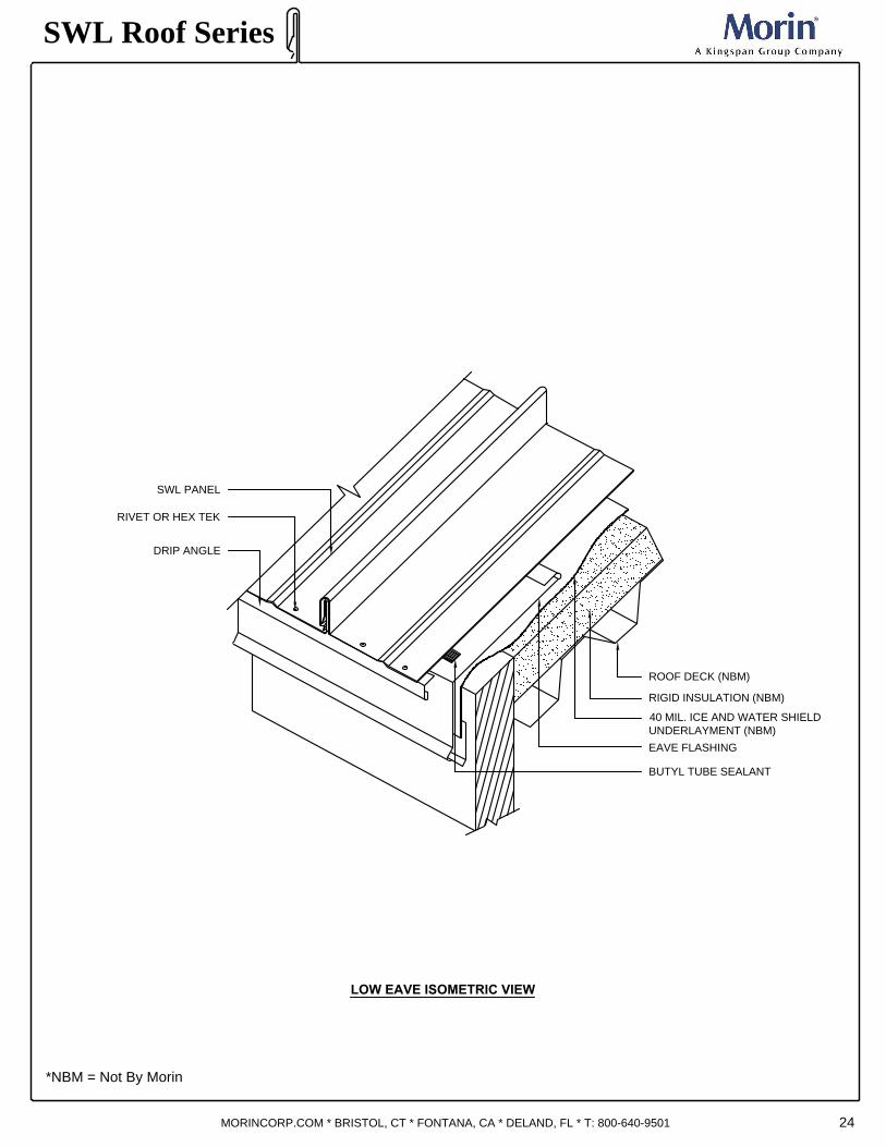
LOW EAVE ISOMETRIC VIEW
SWL Roof Series
*NBM = Not By Morin
MORINCORP.COM * BRISTOL, CT * FONTANA, CA * DELAND, FL * T: 800-640-9501
BUTYL TUBE SEALANT
RIGID INSULATION (NBM)
ROOF DECK (NBM)
RIVET OR HEX TEK
DRIP ANGLE
EAVE FLASHING
SWL PANEL
40 MIL. ICE AND WATER SHIELD
UNDERLAYMENT (NBM)
24

LOW EAVE SECTION
25
SWL Roof Series
*NBM = Not By Morin
MORINCORP.COM * BRISTOL, CT * FONTANA, CA * DELAND, FL * T: 800-640-9501
BUTYL TUBE SEALANT AT
RIB & PAN
EAVE TRIM
UNDERLAYMENT
(NBM)
RIGID INSULATION
(NBM)
ROOF DECK (NBM)
PANCAKE HEAD FASTENERS
(2) PER CLIP MIN.
6
"
-
8
"
M
A
X
I
M
U
M
1"X1" DRIP ANGLE
Note:
Eave design must be able to allow for the total amount of expansion of the panel if the ridge is fixed.
A drip trim should be used to stiffen the flat of the panel and block wind driven rain. This piece also
assists in limiting the amount of bow of the flat under high wind.
2 RIVETS (MIN) OR HEX TEK
PER PANEL
1
"
M
I
N
SWL CLIP
6"X6" BEARING PLATE
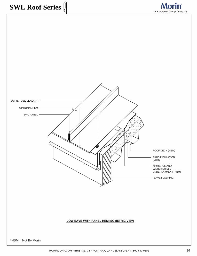
26
BUTYL TUBE SEALANT
RIGID INSULATION
(NBM)
ROOF DECK (NBM)
EAVE FLASHING
SWL PANEL
40 MIL. ICE AND
WATER SHIELD
UNDERLAYMENT (NBM)
OPTIONAL HEM
LOW EAVE WITH PANEL HEM ISOMETRIC VIEW
SWL Roof Series
*NBM = Not By Morin
MORINCORP.COM * BRISTOL, CT * FONTANA, CA * DELAND, FL * T: 800-640-9501

LOW EAVE SECTION WITH PANEL HEM
SWL Roof Series
*NBM = Not By Morin
MORINCORP.COM * BRISTOL, CT * FONTANA, CA * DELAND, FL * T: 800-640-9501
SWL CLIP
BUTYL TUBE SEALANT
AT RIB & PAN
EAVE TRIM
RIGID INSULATION
(NBM)
ROOF DECK (NBM)
PANCAKE HEAD FASTENERS
(2) PER CLIP MIN.
6
"
-
8
"
M
A
X
I
M
U
M
1
"
M
I
N
OPTIONAL HEM
(ALLOW EXPANSION)
UNDERLAYMENT
(NBM)
3
8
"
3
8
"
3
8
"
27
Note:
Since sealant between roof underlayment and panel may limit expansion or rupture, protection against
wind blown water infiltration is provided by folding the panel under, which allows for thermal expansion.
Detail must be designed to allow for maximum thermal movement.
6"X6" BEARING PLATE

HIGH EAVE
28
SWL Roof Series
*NBM = Not By Morin
MORINCORP.COM * BRISTOL, CT * FONTANA, CA * DELAND, FL * T: 800-640-9501
RIDGE CAP
PANCAKE HEAD FASTENERS
(2) PER CLIP MIN.
RIGID INSULATION (NBM)
FASTENERS (5) PER PANEL MIN.
6"X6" BEARING PLATE
ROOF DECK (NBM)
CONTINUOUS "Z" CLOSURE SET IN SEALANT
NOTCHED AROUND PANEL RIBS IN FIELD
HIGH HEAT ICE AND
WATER SHIELD REQ'D
40 MIL MIN. (NBM)
"J" CLOSURE SUPPORT
RIVET
FULLY SEAL LENGTH
OF 'J' CLOSURE
FIX FASTENER (2) PER PANEL

WALL TO ROOF HIGH EAVE
29
SWL Roof Series
*NBM = Not By Morin
MORINCORP.COM * BRISTOL, CT * FONTANA, CA * DELAND, FL * T: 800-640-9501
FASTENERS (2) PER CLIP MIN.
ROOF DECK
(NBM)
SWL CLIP
HIGH EAVE FLASHING
MASONRY FASTENER
BUTYL TUBE SEALANT
FASTENERS (5) PER PANEL MIN.
"J" SUPPORT AT PANEL ENDS
Note:
High eave flashings are similar to ridge conditions. Attention must be given to the design for sealing and panel movement.
URETHANE SEALANT
BETWEEN FLASHING AND MASONRY
FULLY SEAL LENGTH
OF 'J' CLOSURE
6"X6" BEARING PLATE
FIX FASTENER (2) PER PANEL
CONTINUOUS "Z" CLOSURE SET IN SEALANT
NOTCHED AROUND PANEL RIBS IN FIELD
30
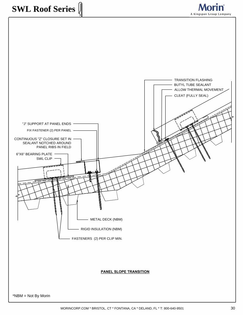
PANEL SLOPE TRANSITION
SWL Roof Series
*NBM = Not By Morin
MORINCORP.COM * BRISTOL, CT * FONTANA, CA * DELAND, FL * T: 800-640-9501
SWL CLIP
BUTYL TUBE SEALANT
FASTENERS (2) PER CLIP MIN.
METAL DECK (NBM)
RIGID INSULATION (NBM)
CONTINUOUS "Z" CLOSURE SET IN
SEALANT NOTCHED AROUND
PANEL RIBS IN FIELD
"J" SUPPORT AT PANEL ENDS
TRANSITION FLASHING
ALLOW THERMAL MOVEMENT
6"X6" BEARING PLATE
CLEAT (FULLY SEAL)
FIX FASTENER (2) PER PANEL

PANEL END & CLOSURE ISOMETRIC
31
SWL Roof Series
*NBM = Not By Morin
MORINCORP.COM * BRISTOL, CT * FONTANA, CA * DELAND, FL * T: 800-640-9501
CONTINUOUS Z METAL CLOSURE
(SEALANT AROUND
RIBS & BOTTOM)
CONTINUOUS J-TRIM (FULLY SEAL)

ROOF TO WALL
32
SWL Roof Series
*NBM = Not By Morin
MORINCORP.COM * BRISTOL, CT * FONTANA, CA * DELAND, FL * T: 800-640-9501
FASTENERS (2)
PER CLIP MIN.
METAL DECK (NBM)
RIGID INSULATION (NBM)
BUTYL SEALANT
SWL CLIP
6
"
-
1
0
"
M
A
X
IM
U
M
CLEAT WITH DOUBLE BEAD CONTINUOUS
1
8
" x1" BUTYL TAPE SEALANT
18 GA GALVANIZED
CAP (NBM)
CURB CAP (NBM)
BUTYL TAPE
SEALANT
BACK PAN
SWL PANEL
CRICKET
(FIELD INSTALLED)
6"X6" BEARING PLATE

LOW EAVE WITH GUTTER
33
SWL Roof Series
*NBM = Not By Morin
MORINCORP.COM * BRISTOL, CT * FONTANA, CA * DELAND, FL * T: 800-640-9501
RIGID INSULATION
(NBM)
ROOF DECK (NBM)
40 MIL ICE AND
WATER SHIELD
UNDERLAYMENT (NBM)
GUTTER
SUPPLEMENTAL GUTTER
SUPPORT BRACKETS
AS REQUIRED 2" WIDE
SWL PANEL
DRIP ANGLE
USE BUTYL TUBE
SEALANT AT PANEL
RIB AND PAN
CLOSED END POP-RIVET
(3) PER PANEL MIN.
STRAPS
STRAP ATTACHED
THOROUGHLY TO GUTTER

LOW EAVE WITH GUTTER
34
Note:
Consideration during design must be given to capacity, overflow, accessibility for cleaning, and
aesthetics. Attachments must provide structural supports and allow for thermal movement.
Protection from ice and snow must be considered during the detailing of this condition. Edge of
gutter should be reinforced in areas of snow or ice accumulation. The edge of the gutter should
be below the roof plane to allow for evacuation of the snow build-up. The gutter should be
independent of the roof panel as not to inhibit the thermal movement of the roof.
SWL Roof Series
*NBM = Not By Morin
MORINCORP.COM * BRISTOL, CT * FONTANA, CA * DELAND, FL * T: 800-640-9501
SWL CLIP
SWL PANEL
40 MIL ICE AND
WATER SHIELD (NBM)
RIGID INSULATION
(NBM)
ROOF DECK
(NBM)
FASTENERS (2)
PER CLIP MIN.
EAVE TRIM
GUTTER
GUTTER STRAP
SUPPLEMENTAL
GUTTER
STRAP 2" WIDE
BUTYL TUBE SEALANT
BETWEEN RIBS AND PAN
1"X1" DRIP ANGLE
6"X6" BEARING PLATE

INTERNAL GUTTER
35
Note:
Where an exposed gutter may distract from the aesthetics of the building, an internal gutter may
be required. The condition and roof design must allow for this condition to be “fixed” against
thermal movement. Considerations must be made in areas of ice or snow to avoid blockage of
the gutter or drains. Overflow scuppers are required at each end of the gutter. This design relies
on sealant to form the weather barrier. Designers should be aware of the hazards and allow for
adequate drainage. Morin requires membrane liner for all internal gutter (NBM). Use larger J-
support for panel with clip relief, pencil ribs and striated.
SWL Roof Series
*NBM = Not By Morin
MORINCORP.COM * BRISTOL, CT * FONTANA, CA * DELAND, FL * T: 800-640-9501
SWL CLIP
BUTYL SEALANT
BETWEEN RIBS AND PAN
GUTTER FLASHING
METAL DECK (NBM)
FASTENERS (2) PER CLIP MIN.
RIGID INSULATION (NBM)
GUTTER DRAIN (NBM)
CONTINUOUS "Z" CLOSURE
SET IN SEALANT NOTCHED
AROUND PANEL RIBS IN FIELD
"J" SUPPORT AT PANEL ENDS
SEAL FULLY
OVERFLOW SCUPPER
AT ENDWALLS
6"X6" BEARING PLATE
FIX FASTENER (2) PER PANEL
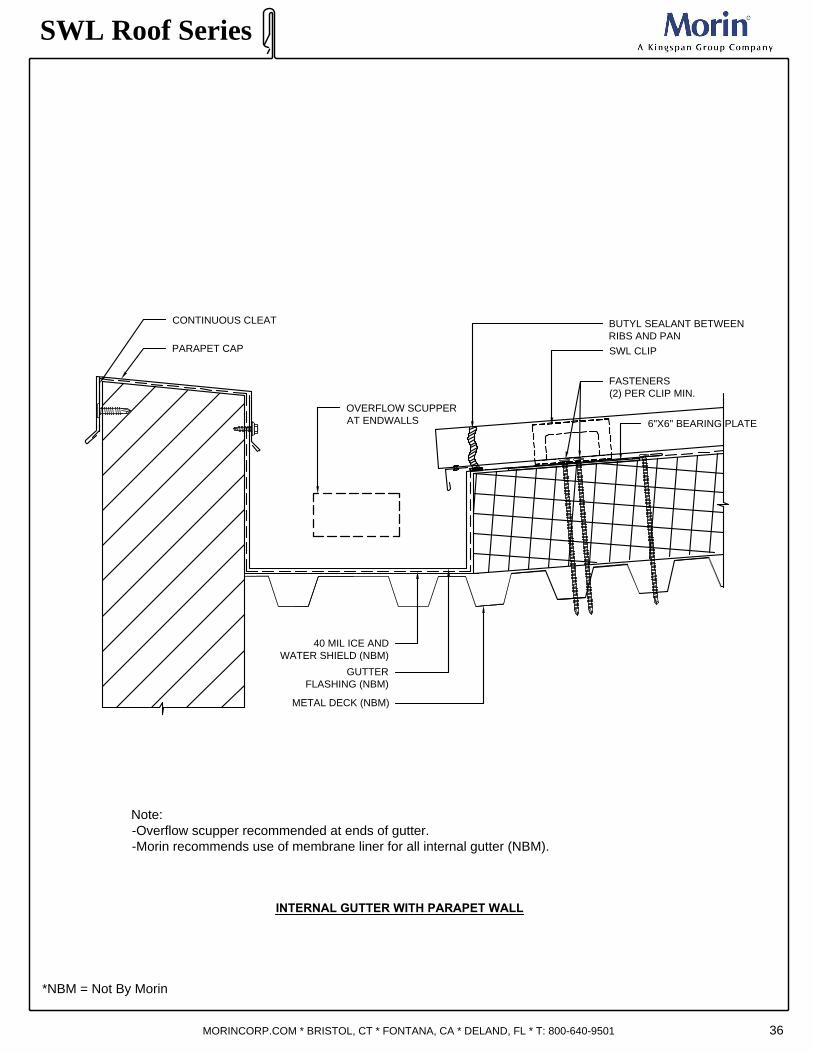
Note:
-Overflow scupper recommended at ends of gutter.
-Morin recommends use of membrane liner for all internal gutter (NBM).
INTERNAL GUTTER WITH PARAPET WALL
36
SWL Roof Series
*NBM = Not By Morin
MORINCORP.COM * BRISTOL, CT * FONTANA, CA * DELAND, FL * T: 800-640-9501
SWL CLIP
METAL DECK (NBM)
FASTENERS
(2) PER CLIP MIN.
40 MIL ICE AND
WATER SHIELD (NBM)
PARAPET CAP
CONTINUOUS CLEAT
GUTTER
FLASHING (NBM)
BUTYL SEALANT BETWEEN
RIBS AND PAN
OVERFLOW SCUPPER
AT ENDWALLS
6"X6" BEARING PLATE

Note:
-Overflow scupper recommended at ends of gutter.
-Morin recommends use of membrane liner for all internal gutter (NBM).
INTERNAL GUTTER WITH SAW TOOTH ROOF
37
SWL Roof Series
*NBM = Not By Morin
MORINCORP.COM * BRISTOL, CT * FONTANA, CA * DELAND, FL * T: 800-640-9501
SWL CLIP
FASTENERS (2)
PER CLIP MIN.
METAL DECK (NBM)
RIGID INSULATION
(NBM)
GUTTER DRAIN (NBM)
OVERFLOW SCUPPER
AT ENDWALLS
GUTTER SUPPORT (NBM)
BUTYL SEALANT
BETWEEN RIBS
AND PAN
6"X6" BEARING PLATE
OVERFLOW SCUPPER
AT ENDWALLS
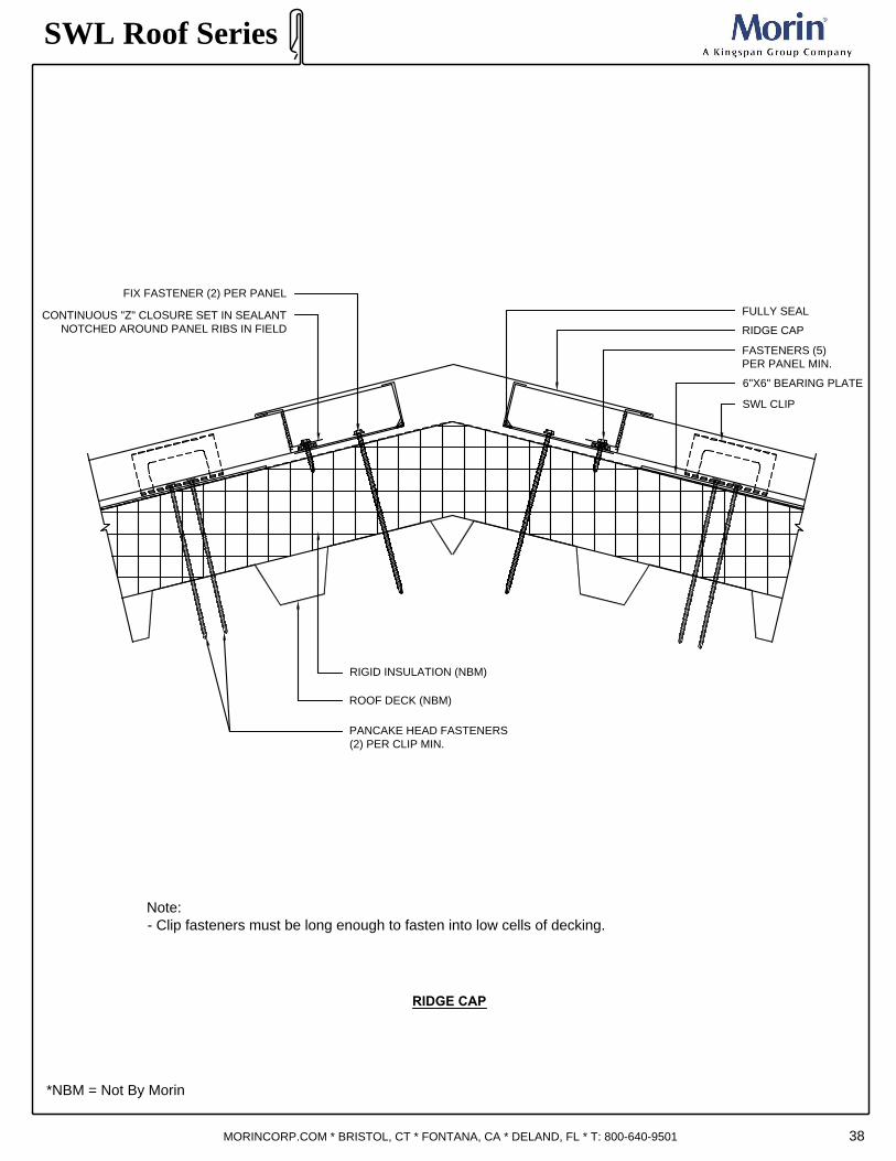
RIDGE CAP
38
Note:
- Clip fasteners must be long enough to fasten into low cells of decking.
SWL Roof Series
*NBM = Not By Morin
MORINCORP.COM * BRISTOL, CT * FONTANA, CA * DELAND, FL * T: 800-640-9501
FASTENERS (5)
PER PANEL MIN.
SWL CLIP
RIDGE CAP
RIGID INSULATION (NBM)
ROOF DECK (NBM)
PANCAKE HEAD FASTENERS
(2) PER CLIP MIN.
6"X6" BEARING PLATE
CONTINUOUS "Z" CLOSURE SET IN SEALANT
NOTCHED AROUND PANEL RIBS IN FIELD
FULLY SEAL
FIX FASTENER (2) PER PANEL

Note:
- Clip fasteners must be long enough to fasten into low cells of decking.
SWL Roof Series
*NBM = Not By Morin
MORINCORP.COM * BRISTOL, CT * FONTANA, CA * DELAND, FL * T: 800-640-9501
4" AS REQ.
SWL CLIP
RIDGE CAP
6"X6" BEARING PLATE
FASTENERS
(2) PER CLIP MIN.
RIGID INSULATION
(NBM)
ROOF DECK (NBM)
CONTINUOUS "Z" CLOSURE
NOTCH AROUND RIBS IN FIELD
FULLY SEAL AROUND
NOTCHED & BOTTOM RIBS
FASTENER W/ NEOPRENE
WASHER AT 12" O.C.
VENTED RIDGE
39
FULLY SEALANT
VENTABLE MATERIAL (NBM)
FIX FASTENER (2) PER PANEL
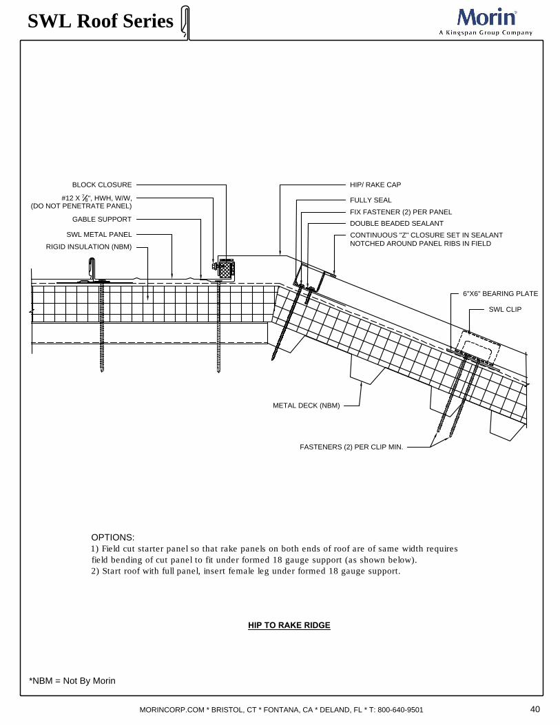
OPTIONS:
1) Field cut starter panel so that rake panels on both ends of roof are of same width requires
field bending of cut panel to fit under formed 18 gauge support (as shown below).
2) Start roof with full panel, insert female leg under formed 18 gauge support.
40
HIP TO RAKE RIDGE
SWL Roof Series
*NBM = Not By Morin
MORINCORP.COM * BRISTOL, CT * FONTANA, CA * DELAND, FL * T: 800-640-9501
SWL METAL PANEL
GABLE SUPPORT
RIGID INSULATION (NBM)
METAL DECK (NBM)
SWL CLIP
#12 X
7
8
", HWH, W/W,
(DO NOT PENETRATE PANEL)
CONTINUOUS "Z" CLOSURE SET IN SEALANT
NOTCHED AROUND PANEL RIBS IN FIELD
FASTENERS (2) PER CLIP MIN.
DOUBLE BEADED SEALANT
HIP/ RAKE CAP
6"X6" BEARING PLATE
FULLY SEAL
BLOCK CLOSURE
FIX FASTENER (2) PER PANEL

41
HIP TO RAKE RIDGE ISOMETRIC
SWL Roof Series
*NBM = Not By Morin
MORINCORP.COM * BRISTOL, CT * FONTANA, CA * DELAND, FL * T: 800-640-9501
RIDGE/ HIP CAP
METAL RIDGE/HIP CLOSURE SUPPLIED
10' LONG BEVEL CUT TO FIT SLOPE

42
RAKE DETAIL
SWL Roof Series
*NBM = Not By Morin
MORINCORP.COM * BRISTOL, CT * FONTANA, CA * DELAND, FL * T: 800-640-9501
#12 X
7
8
", HWH, W/W,
(DO NOT PENETRATE PANEL)
FOAM BLOCK
W/ BUTYL SEALANT
RAKE TRIM
RIGID INSULATION (NBM)
ROOF DECK (NBM)
SWL PANEL
CONT. GABLE SUPPORT
6"X6" BEARING PLATE
SWL PANEL CLIP
Note:
The roof and structure must be allowed to move independently of each other. Thermal
movement cannot be restricted. The gable clip is designed to allow this movement while
holding down the roof panel. It will also hold the roof panel off the structure the same distance
as both hold down clips. Since the gable clip is stationary, the gable trim piece can be
attached to it for positive anchoring. The design of the gable flashing can be modified to suit
the individual project as long as the basic concept is maintained. Spacing for gable clip
is 2’-0” o.c. maximum. For longer purlin spacing a gable clip trim is available in 10’-0” sections.
Options:
1) Field cut starter panel so that rake panels on both ends of roof are of same width. Requires
field bending of cut panel to fit under formed gable support (as shown below).
2) Start roof with full panel, insert female leg under formed gable support.
3) Clip fasteners must be long enough to fasten into low cells of decking

RAKE AT STEPPED EAVE
43
SWL Roof Series
*NBM = Not By Morin
MORINCORP.COM * BRISTOL, CT * FONTANA, CA * DELAND, FL * T: 800-640-9501
RIGID INSULATION (NBM)
ROOF DECK (NBM)
6"X6" BEARING PLATE
SWL PANEL CLIP
RAKE FLASHING
BUTYL TUBE SEALANT
Note:
Clip fasteners must be long enough to fasten into low cells of decking.
SWL PANEL
PANCAKE HEAD FASTENER
WITH BUTYL TUBE SEALANT

SWL Roof Series
*NBM = Not By Morin
MORINCORP.COM * BRISTOL, CT * FONTANA, CA * DELAND, FL * T: 800-640-9501 44
RAKE INSTALLATION
COMPLETE ASSEMBLY
STEP: 1
FASTEN RAKE CLEAT
STEP: 2
RAKE FLASHING
STEP: 3
2 ROWS OF CONTINUOUS
BUTYL SEALANT
STEP: 4
FIELD CUT PANEL
STEP: 5
FIELD NOTCH AND BEND
TO CREATE OPEN HEM

45
WALL TO RAKE FLASHING
Note:
Since the width of the standing seam roof can vary due to compression or spreading during the installation, the
module can be altered to minimize the endwall trim width. In cases of fixed panel width or module, the designer
should center the roof panels if possible, to reduce the width of the trim pieces. The endwall flash should be
sloped to allow drainage of water to avoid leaks at joints in the trim. Reinforcing of the trim may be required at
large widths to support the joints.
SWL Roof Series
*NBM = Not By Morin
MORINCORP.COM * BRISTOL, CT * FONTANA, CA * DELAND, FL * T: 800-640-9501
RAKE FLASHING
FOAM BLOCK
W/ BUTYL SEALANT
FASTENERS AS REQUIRED
RIGID INSULATION (NBM)
METAL DECK (NBM)
METAL WALL
RAKE FLASHING
FLASHING
SWL PANEL CLIP
GABLE SUPPORT
6"X6" BEARING PLATE
URETHANE SEALANT
BETWEEN FLASHING
AND MASONRY
12
2:12 MIN

RAKE AT SLOPING TO FLAT ROOF
46
SWL Roof Series
*NBM = Not By Morin
MORINCORP.COM * BRISTOL, CT * FONTANA, CA * DELAND, FL * T: 800-640-9501
RIGID INSULATION (NBM)
METAL DECK (NBM)
FASTENERS (2)
PER CLIP MIN.
BUTYL TUBE SEALANT BETWEEN
RIBS AND PAN
TRANSITION FLASHING
SWL CLIP
6" X 6" BEARING PLATE
ALIGN FACE OF TRIM WITH
CONTINUOUS RAKE CLIP AND STEP
RAKE FLASHING
PANEL LEG CUT-OFF
RIVET
FULLY SEAL
TRIM
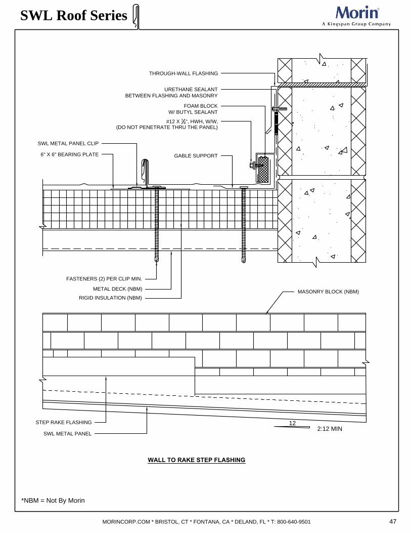
WALL TO RAKE STEP FLASHING
SWL Roof Series
*NBM = Not By Morin
MORINCORP.COM * BRISTOL, CT * FONTANA, CA * DELAND, FL * T: 800-640-9501
THROUGH-WALL FLASHING
STEP RAKE FLASHING
MASONRY BLOCK (NBM)
SWL METAL PANEL CLIP
GABLE SUPPORT
FASTENERS (2) PER CLIP MIN.
RIGID INSULATION (NBM)
METAL DECK (NBM)
#12 X
7
8
", HWH, W/W,
(DO NOT PENETRATE THRU THE PANEL)
SWL METAL PANEL
FOAM BLOCK
W/ BUTYL SEALANT
6" X 6" BEARING PLATE
URETHANE SEALANT
BETWEEN FLASHING AND MASONRY
12
47
2:12 MIN

48
WALL TO RAKE EXPANSION JOINT
OPTIONS:
1) Field cut starter panel so that rake panels on both ends of roof are of same width requires
field bending of cut panel to fit under continuous rake clip (as shown below).
2) start roof with full panel, insert female leg under continuous rake clip.
SWL Roof Series
*NBM = Not By Morin
MORINCORP.COM * BRISTOL, CT * FONTANA, CA * DELAND, FL * T: 800-640-9501
METAL DECK (NBM)
RIGID INSULATION (NBM)
1" 1" 1"
FOAM BLOCK
W/ BUTYL SEALANT
CONT. GABLE SUPPORT
THROUGH-WALL FLASHING
6"X6" BEARING PLATE
6"X6" BEARING PLATE
#12 X
7
8
", HWH, W/W,
(DO NOT PENETRATE PANEL)
COMPRESSIBLE INSULATION
(NBM)

49
RIGID INSULATION (NBM)
METAL DECK (NBM)
OPTIONS:
1) Field cut starter panel so that rake panels on both ends of roof are of same width requires field bending of cut panel
to fit under formed 18 gauge support (as shown below).
2) Start roof with full panel, insert female leg under formed 18 gauge support.
3) Use J- support for panel with clip relief, pencil ribs and striated.
CONTINUOUS "Z" CLOSURE
SET IN SEALANT NOTCHED AROUND
PANEL RIBS IN FIELD
FASTENERS (2) PER CLIP MIN.
DOUBLE BEADED SEALANT
"J" SUPPORT AT PANEL ENDS
HIP/ RAKE CAP
HIP TO RAKE TRANSITION
SLO
PE
MIN
2:1
2
SWL Roof Series
*NBM = Not By Morin
MORINCORP.COM * BRISTOL, CT * FONTANA, CA * DELAND, FL * T: 800-640-9501
SWL CIP
FULLY SEAL
BUTYL TUBE SEALANT BETWEEN
RIBS AND PAN
CLEAT OPTION
6"X6" BEARING
PLATE
PANEL HEM
(ALLOW EXPANSION)
SEAL
DRIP ANGLE
FIX FASTENER (2) PER PANEL

PANEL EXPANSION JOINT
50
Some building designs require an expansion joint to accommodate movement of the structure.
The detail must be designed to allow movement in the anticipated directions. Several proprietary
products are available which can be integrated into this basic design.
Options:
1) Field cut starter panel so that rake panels on both ends of roof are of same width. Requires
field bending of cut panel to fit under gable support (as shown below).
2) Start roof with full panel, insert female leg under gable support.
SWL Roof Series
*NBM = Not By Morin
MORINCORP.COM * BRISTOL, CT * FONTANA, CA * DELAND, FL * T: 800-640-9501
METAL DECK (NBM)
RIGID INSULATION (NBM)
1" 1" 1"
#12 X
7
8
", HWH, W/W,
(DO NOT PENETRATE PANEL)
FOAM BLOCK
W/ BUTYL SEALANT
SWL METAL PANEL
CONTINUOUS GABLE SUPPORT
BUTYL TUBE SEALANT ON TOP
OF GABLE SUPPORT
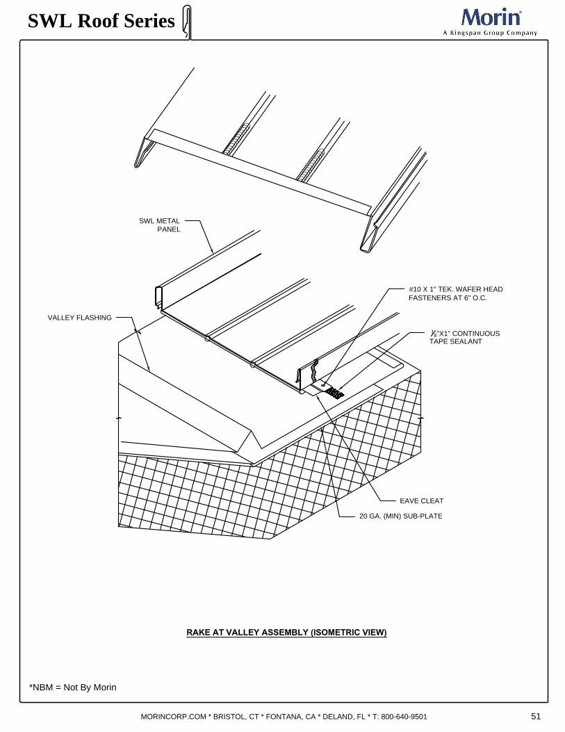
RAKE AT VALLEY ASSEMBLY (ISOMETRIC VIEW)
51
SWL Roof Series
*NBM = Not By Morin
MORINCORP.COM * BRISTOL, CT * FONTANA, CA * DELAND, FL * T: 800-640-9501
VALLEY FLASHING
EAVE CLEAT
1
8
"X1" CONTINUOUS
TAPE SEALANT
20 GA. (MIN) SUB-PLATE
SWL METAL
PANEL
#10 X 1" TEK. WAFER HEAD
FASTENERS AT 6" O.C.

52
RAKE AT VALLEY DETAIL
Valley flashing must allow for sufficient area to carry anticipated runoff without overflow or
backup under the roof edge. The raised center assists in diversion of water and allows for
thermal movement.
SWL Roof Series
*NBM = Not By Morin
MORINCORP.COM * BRISTOL, CT * FONTANA, CA * DELAND, FL * T: 800-640-9501
SWL CLIP
BUTYL TUBE SEALANT
BETWEEN RIBS AND PAN
RIGID INSULATION (NBM)
METAL DECK (NBM)
VALLEY FLASHING
FASTENERS (2)
PER CLIP MIN.
S
A
M
E
H
T
.
A
S
P
A
N
E
L
L
A
R
G
E
R
A
T
L
O
W
S
L
O
P
E
FASTENERS 6" O.C
6
"
M
I
N
.
1
8
" X 1" CONTINUOUS
DOUBLE BEAD
BUTYL TAPE SEALANT
SWL PANEL
20 GA. (MIN) SUB-PLATE
6"X6" BEARING PLATE
CLEAT

53
EQUIPMENT CURB FLASHING PLAN VIEW
Note:
Large openings for equipment or hatchways require a curb with means of diverting the water
around the opening. Set and secure roof curb on support framing. At least two parallel curb walls
must be on support framing. In high load areas engineer needs to check for proper
support. Loads shall not be supported by cantilever sections exceeding 1’0” in length.
Cut roof panels to fit snugly around curb walls and to within 1” of the water diverter. Apply a wide
band of tape caulk to the top side of curb flanges. Install and seal closures in ends of panels. Plug
and caulk all rib ends. Press roof panels into place. Fasten roof panels through curb flanges to
support steel using suitable fasteners for the roof system. A spacing of approximately 3” should
be used. Inspect installation and fasteners. Apply an exterior sealant to seal seams around all
sides of curb to insure a weathertight seal. In all cases the curb assembly is capped by a collar or
skirt that extends down over the curb. Curb to be fixed to panel only. Allowance must be made at
equipment curb and trim to allow for thermal movement.
SWL Roof Series
*NBM = Not By Morin
MORINCORP.COM * BRISTOL, CT * FONTANA, CA * DELAND, FL * T: 800-640-9501
12" M
IN
BA
CK
P
AN
5"
AP
RO
N
CU
RB
LE
NG
TH
6"
6" M
IN
6" M
IN
6" MIN
A
B B
C
D
C
D
A

APRON
54
SWL Roof Series
*NBM = Not By Morin
MORINCORP.COM * BRISTOL, CT * FONTANA, CA * DELAND, FL * T: 800-640-9501
SIDE FLASHING
BACK PAN
CURB PENETRATION
1
2
"
M
I
N
.
1" TABS
EQUIPMENT CURB FLASHING
BACK PAN
SIDE FLASHING
1" TABS
CU
RB
HE
IG
HT
1
2
"
M
I
N
.
1
1
2
"
V
A
R
I
E
S
CU
RB
HE
IG
HT
C
U
R
B
L
E
N
G
T
H
CU
RB
HE
IG
HT
5
"
2"
5
"
EQUIPMENT CURB FLASHING (ISOMETRIC VIEW A)

EQUIPMENT CURB - SECTION B
55
SWL Roof Series
*NBM = Not By Morin
MORINCORP.COM * BRISTOL, CT * FONTANA, CA * DELAND, FL * T: 800-640-9501
FASTENERS (2) PER CLIP MIN.
METAL DECK (NBM)
RIGID INSULATION (NBM)
18 GA GALVANIZED
CAP (NBM)
6" minimum
CURB CAP (NBM)
TRANSITION FLASHING
PANEL LEG CUT-OFF
RIVET
FULLY SEAL
TRIM
6"X6" BEARING PLATE

EQUIPMENT CURB - SECTION C
56
SWL Roof Series
*NBM = Not By Morin
MORINCORP.COM * BRISTOL, CT * FONTANA, CA * DELAND, FL * T: 800-640-9501
FASTENERS (2)
PER CLIP MIN.
METAL DECK (NBM)
RIGID INSULATION (NBM)
BUTYL TUBE SEALANT
SWL CLIP
6" -10" M
A
X
IM
U
M
DOUBLE BEAD CONTINUOUS
1
8
" x1" BUTYL TAPE SEALANT
18 GA GALVANIZED
CAP (NBM)
CURB CAP (NBM)
BUTYL TAPE
SEALANT
BACK PAN
SWL PANEL
4
"
M
I
N
.
6"X6"
BEARING
PLATE

EQUIPMENT CURB - SECTION D
57
SWL Roof Series
*NBM = Not By Morin
MORINCORP.COM * BRISTOL, CT * FONTANA, CA * DELAND, FL * T: 800-640-9501
CURB CAP (NBM)
FASTENERS (2) PER CLIP MIN.
METAL DECK (NBM)
RIGID INSULATION (NBM)
18 GA GALVANIZED
CAP (NBM)
APRON
SWL CLIP
CONTINUOUS "Z" CLOSURE SET IN SEALANT
NOTCHED AROUND PANEL RIBS IN FIELD
DOUBLE BEAD
1
8
"X1" BUTYL TAPE SEALANT
"J" SUPPORT AT PANEL ENDS
FULLY SEAL
6"X6" BEARING PLATE
FIX FASTENER (2) PER PANEL

PIPE PENETRATION DETAIL
58
Notes:
1) Attach Dektite or similar to panel only to allow thermal movement.
2) Center pipe penetration within panel width if possible.
3) Keep base of Dektite away from panel edges (minimum 2").
4) Provide 1" clearance between edge of pipe and panel hole.
SWL Roof Series
*NBM = Not By Morin
MORINCORP.COM * BRISTOL, CT * FONTANA, CA * DELAND, FL * T: 800-640-9501
#14 X
7
8
", TEK 3, HWH, W/W,
PAINTED 2" O.C.
BEFORE INSTALLING THE DEKTITE OR SIMILAR,
PLACE CONTINUOUS BEAD OF SEALANT AROUND
PIPE AT HEIGHT OF BOOT TOP
STAINLESS STEEL
PIPE CLAMP
APPLY SEALANT BETWEEN BOTTOM
OF DEKTITE AND TOP OF PANEL

GUTTER FLASHING CONDITIONS
59
SWL Roof Series
*NBM = Not By Morin
MORINCORP.COM * BRISTOL, CT * FONTANA, CA * DELAND, FL * T: 800-640-9501
6"
1
8
" GAP
GUTTER SPLICE PLATE
GUTTER LAP DETAIL
4"
2" 1"1"
1" LAP
GUTTER EXPANSION DETAIL
3
4
" 1
1
2
"
END CAP
END CAP
END CAP
4
"
GUTTER EXPANSION DETAIL
3
4
"
EXPANSION
COVER
SET IN SEALANT
Note: Use expansion joint every 25'

RAKE AND EAVE FLASHING CONDITION
60
SWL Roof Series
*NBM = Not By Morin
MORINCORP.COM * BRISTOL, CT * FONTANA, CA * DELAND, FL * T: 800-640-9501
4"
RAKE LAP DETAIL
6
"
L
A
P
4"
EAVE LAP DETAIL
EAVE INSIDE SPLICE PLATE
4
"
N
O
T
C
H
NOTCH IN BOTTOM LEG
Note: Shingle laps in direction
of water flow.
6"
4
"
N
O
T
C
H
NOTCH IN BOTTOM LEG
SPLICE PLATE

6"
RIDGE CAP - LAP DETAIL
6"
HIP CAP - LAP DETAIL
6
"
L
A
P
W
A
T
E
R
F
L
O
W
BUTYL SEALANT
BUTYL SEALANT
6" NOTCH IN
THE BOTTOM LEG
TYP. LAP DETAIL
RIDGE AND HIP FLASHING CONDITION
6
"
L
A
P
FASTEN PANEL CLOSURE
TO PANEL CLOSURE TO
FIX IN PLACE
Note: Field Notch Hems As Required.
SWL Roof Series
*NBM = Not By Morin
MORINCORP.COM * BRISTOL, CT * FONTANA, CA * DELAND, FL * T: 800-640-9501 61

SWL Roof Series
*NBM = Not By Morin
MORINCORP.COM * BRISTOL, CT * FONTANA, CA * DELAND, FL * T: 800-640-9501
DOWN SPOUT OUTLET
CENTER HEM
TYPICAL 4" X 3" ELBOW
DIMENSIONS WITH 6"
RETURN
DOWNSPOUT
4"
3"
4"
3"
62

SWL Roof Series
*NBM = Not By Morin
MORINCORP.COM * BRISTOL, CT * FONTANA, CA * DELAND, FL * T: 800-640-9501
SIDE VIEW
ASSEMBLY
SNOW GUARD
2" STRIP OF MATCHED
GAUGE & COLOR STRIP
CROSS MEMBER CONTINUOUS
SNOW GUARD (ISOMETRIC VIEW)
S
L
O
P
E
Note:
1) Mount s-5-z clamp directly to top of panel rib with set screw.
2) Install 2" color strip from panel flatstock into snow guard.
3) Connect clip to snow guard, one per panel, centered.
4) Connect assembly to s-5-z clamps.
1
2
"
M
I
N
63

SIDE VIEW
LIGHTNING PROTECTION
Note:
-Coated cables and clamp required as necessary to prevent galvanic reaction.
SWL Roof Series
*NBM = Not By Morin
MORINCORP.COM * BRISTOL, CT * FONTANA, CA * DELAND, FL * T: 800-640-9501
LIGHTNING ROD AIR TERMINAL
CONDUCTOR CABLE
CLAMP
ALUMINUM TOP MOUNT
SECTION CUT VIEW
CONDUCTOR CABLE
ALUMINUM TOP MOUNT
CLAMP
SWL PANEL
64

BUTYL TUBE SEALANT
RIVET TYPICAL
FIELD NOTCH AND BEND
40 MIL ICE & WATER SHEILD (NBM)
SWL CLIP
PANEL NOTCH
SWL PANEL
SWL Roof Series
*NBM = Not By Morin
MORINCORP.COM * BRISTOL, CT * FONTANA, CA * DELAND, FL * T: 800-640-9501 65
KNUCKLE (KNEE) DETAIL
(2) EXPOSED FASTENERS IN
PAN TO MAKE FIXED POINT.
NEED TO ALLOW RIDGE &
EAVE TO FLOAT.
FASTENERS
(2) PER CLIP MIN.
METAL DECK (NBM)
RIGID INSULATION (NBM)
6"X6" BEARING
PLATE
PANCAKE HEAD
FASTENERS
20GA. MIN SUB-PLATE

KNUCKLE (KNEE) ISOMETRIC
NOTES:
- All dimensions are nominal.
- Fabricate trim to fit inside and outside of panel seam as req'd.
66
SWL Roof Series
*NBM = Not By Morin
MORINCORP.COM * BRISTOL, CT * FONTANA, CA * DELAND, FL * T: 800-640-9501
*KNEE-CAP SUPPLIED
@ 10'-0" LENGTHS
1
0
'
-
0
"
SEALANT (TYP.)
APPLY SEALANT UNDER
KNEE-CAP
& AT THE FOLD
20GA. MIN SUB. PLATE

TECHNICAL BULLETIN 1040
LIGHTNING AND METAL ROOFING
We live in an electronic age, with computers and other sensitive electrical and electronic equipment present not
only in every workplace, but also in most households. The element of personal safety notwithstanding, more
and more people are considering lightning protection for their home or business. When a metal roof is
employed on a
project, it seems to heighten peoples awareness of lighting, and some question whether or not the use of
metallic roofing increases the risk of lightning strike. Metal roofing does not in any way increase this risk.
Lightning is a flow of electrical current between earth and sky The result of this electrical flow can be millions of
volts. There is still much that is not known about lightning, but most experts agree that a path of ionization
begins from the cloud and extends earthward. This path of ionization is the beginning of, and establishes the
route for a lightning strike. The more dramatic part of the strike occurs when electrons race upward from
earth-to-sky along this route. This is the flash of light with which we are all familiar. It is also the phase of the
strike which poses the threat of damage. As is the case with any flow of electrical current, lightning will follow
the path of least resistance. if the electrical charge is strong enough, it will also arc from one substance to
another. It is the resistance to the flow of this electricity which generates heat energy and can cause
explosions, and other damage.
In assessing the risk involved with lightning striking any structure, two different subject areas should be
analyzed. The first has to do with probability of a strike; the second has to do with consequence of the strike.
There is no measure known which can lessen the probability of a lightning strike, except perhaps physically
moving the location of a structure. The use of lightning protection systems may, however, lessen consequence
of a strike should one occur.
The probability of lightning strike is determined by a number of factors:
1. The topography in the area of the subject facility. Probability of strike is higher if the project is located on a
mountain top or hill top as opposed to a field.
2. Size and height of the subject structure. A tall building or one covering more ground area is more likely to be
struck than a short or small building. A tall, slender structure (such as a steeple or lighthouse) is also a more
likely candidate for a strike.
3. Relative location of the subject structure with respect to nearby larger and taller structures. Presence of a
very tall structure in proximity to a small, short building will tend to further reduce the likelihood of a strike to the
small building.
4. Frequency and severity of thunderstorm activity in the geographic area of the project. As can be appreciated
by reviewing the above factors, the probabilities of a strike to a metal roofed structure are no more or less than
any other kind of structure, as these probabilities have to do with height and size of the structure and its
surroundings, rather than its construction materials.
As can be appreciated by reviewing the above factors, the probabilities of a strike to a metal roofed structure
are no more or less than any other kind of structure, as these probabilities have to do with height and size of
the structure and its surroundings, rather than its construction materials. In order to adequately assess risks
involved with lightning events, the consequence of a strike must also be studied. In other words, what if
lightning does strike a subject building— what will happen? Obviously, there is a potential threat to human life
associated with a lightning strike in addition to the threat of damage to either the contents of the building, or the
building itself, or both. These threats are affected by the following factors:
SWL Roof Series
MORINCORP.COM * BRISTOL, CT * FONTANA, CA * DELAND, FL * T: 800-640-9501 67

TECHNICAL BULLETIN 1040
LIGHTNING AND METAL ROOFING
1. THE CONSTRUCTION MATERIALS USED FOR BOTH FRAMING AND ROOF COVERINGS:
If these materials are (electrically) conductive, the threat of fire and explosion are both reduced, also reducing
the threat to human life. If these materials are noncombustible the threat of damage to them is reduced, and they
will not contribute a fuel source to any fire resulting from a lightning strike.
2. PHYSICAL CONTENTS OF A BUILDING:
If contents are flammable, or explosive, risks of the perils of fire are obviously increased. If contents are highly
sensitive electronic or other equipment. highly valuable or irreplaceable items, then the consequence of loss is
intensified.
3. HUMAN OCCUPANCY:
Buildings which are heavily occupied are considered to be at higher risk than unoccupied or sparsely occupied
buildings. Also, the type of occupancy has a bearing, if a fire results from a lightning strike, the risk to human life
is greater if occupants are handicapped or non-ambulatory & cannot be quickly evacuated.
4. REMOTENESS OF THE BUILDING:
If the building is remote with respect to fire fighting and medical emergency response, the risks of physical loss
due to fire as well as human perils are increased.
Because metal roofing is both an electrical conductor, and a noncombustible material, the risks associated with
its use and behavior during a lightning event make it the most desirable construction material available. This fact
not withstanding, and in view of the many variables which contribute to lightning risk, it may, in some cases, be
prudent to consider lightning protection. A lightning protection system provides for a continuous conductor from
earth to sky (and vice-versa) so that the electrical charge is furnished an obvious path through which to flow,
thereby reducing the risk to (electrically) resistive construction materials and human life.
For additional information see:
NFPA 780 Standard for the
Installation of Lightning Protection
Systems.1995 edition. National Fire
Protection Association, Quincy, Mass.
This technical bulletin has been
distributed, prior to publication,
for review and comment by those
organizations believed to have a
direct interest in and knowledge
of the subject matter.
SWL Roof Series
MORINCORP.COM * BRISTOL, CT * FONTANA, CA * DELAND, FL * T: 800-640-9501 68

TECHNICAL BULLETIN 1050
METAL ROOF COATING AND MAINTENANCE
CLEANING PAINTED FLUOROCARBON SURFACES:
While factory applied finishes for metal building panels are so durable that they will last many years longer than
ordinary paints, it is desirable to clean them thoroughly on a routine basis. Apparent discoloration of the paint
may occur when it has been exposed in dirt-laden atmospheres for long periods of time. Slight chalking may also
cause some change in appearance in areas of strong sunlight. A thorough cleaning will generally restore the
appearance of these buildings and render repainting unnecessary. An occasional light cleaning will also help
maintain an aesthetically pleasing appearance. For any cleaning method used, it is recommended that the
process be tested on a small inconspicuous area before use on a large scale. To maintain the original finish of
the building panels, the only regular maintenance necessary is that of an annual washing. Mild solutions of
detergents or household ammonia will aid in the removal of most dirt, and the following are recommended levels:
1. One cup of common detergent which contains less than 0.5% phosphate (example - “Tide”), dissolved
into 5 gallons of water. NOTE: The use of detergents containing greater than 0.5% phosphate are not
recommended for use in general cleaning of building panels. Never mix cleaners, since this could be
ineffective as well as dangerous. For example, detergents containing ammonia or ammonia compounds
mixed with bleach (which contains chlorine) can result in harmful vapors being formed.
2. One cup of household ammonia dissolved into 5 gallons of water (room temperature).
Working from the top to the bottom of the panels, the building may be washed with either solution using a well
soaked cloth, sponge, brush (with very soft bristles) or low pressure spray washer. The use of scouring powders
or industrial solvents are not recommended since these agents may damage the film, or leave unsightly sources
for dirt accumulation.
Solvent containing cleaners (examples - “Fantastic” or “Formula 409”) are very effective and can be used without
concern. If mildew or other fungal growth is a problem and cannot be removed as outlined above, household
bleach—mixed at a concentration of one gallon bleach to five gallons of water, along with one cup of mild soap
to aid wetting—is recommended.
Once the building is washed, thorough rinsing with clear water is necessary to eliminate the possibility of residue.
Failure to remove all residue from these cleaning steps may damage the film.
POLYVINYLIDENE FLUORIDE (PVDF) AND PLASTISOL COATINGS
Polyvinylidene fluoride (PVDF) and plastisol present relatively nonadherent surfaces to airborne soil. If needed, a
variety of methods for removal of surface deposits is available. Two precautions are given:
1. Do not use wire brushes, abrasives, or similar cleaning tools which will mechanically abrade the coating
surface.
2. In general, the cleaning agents listed below should be tested on a small, inconspicuous area before use on
a large scale.
HOT OR COLD DETERGENT SOLUTIONS
A 5% solution in water of commonly used commercial and industrial detergents will not have any effect on the
metal panel surface. Washing with these solutions should be followed by a thorough rinse of water. A cloth or
soft bristle brush should be used.
SWL Roof Series
MORINCORP.COM * BRISTOL, CT * FONTANA, CA * DELAND, FL * T: 800-640-9501 69

TECHNICAL BULLETIN 1050
METAL ROOF COATING AND MAINTENANCE
CLEANING PAINTED SURFACES:
SOLVENTS
Most organic solvents are flammable and/or toxic and must be handled following manufacturer’s
recommendations. They should be kept away from open flames, sparks, electrical motors and used with
adequate ventilation and protective equipment.
Solvents that may be used to remove non-water soluble deposits (examples - tar, grease, oil paint, graffiti,
sealants...) from PVDF and plastisol surfaces include:
1. Alcohols -
· Denatured alcohol (ethanol)
· Isopropyl (rubbing alcohol)
· Methanol (wood alcohol)
2. Petroleum Products and Turpentine-
· VM&P naphtha (benzine)
· Mineral spirits (oleum)
· Kerosene
· Turpentine (wood or gum spirits)
· Oxalic acid
3. Aromatic and Chlorinated -
· Xylol (Xylene)
· Toluol (Toluene)
· Perchlorethylene (Perclene)
· Trichlorethylene (Triclene)
These solvents should be used with caution on PVDF and plastisol surfaces. A small area should be tested
before general application; contact should be limited to five minutes.
4. Ketones, Esters, Lacquer thinner, Paint Remover.
· Methyl ethyl ketone (MEK)
· Methyl isobutyl ketone (MIBK)
· Ethyl acetate (nail polish remover)
· Butyl acetate
· Lacquer thinner
· Paint remover (non-flammable)
These solvents should be used with caution on PVDF and plastisol surfaces. A small area should be tested
before general application; contact should be limited to one minute. Paint removers should be carefully tested
on small areas following the manufacturer’s application recommendations.
5. Acetone should not be used on PVDF and plastisol surfaces.
CHEMICAL SOLUTIONS
Sodium hypochlorite solution (Laundry bleach, Clorox)
Hydrochloric acid (muriatic acid)
Acid solutions are corrosive and toxic. They should be tested on small areas before general application;
contact should be limited to five minutes. The panel surface should be thoroughly flushed with water after the
chemical solution washing.
GRAFFITI
Graffiti presents a special problem because of the many possible agents used, generally aerosol paint. It is
recommended that less active solvents (examples - alcohols, petroleum solvents and turpentine, aromatic and
chlorinated) be tried initially, followed by stronger solvents (examples -ketones, esters, lacquer thinner, paint
remover). If none of these are satisfactory, it may be necessary to resort to touch-up paint, total repainting or
replacement.
SWL Roof Series
MORINCORP.COM * BRISTOL, CT * FONTANA, CA * DELAND, FL * T: 800-640-9501 70

TECHNICAL BULLETIN 1060
OIL CANNING
What is oil canning?
Oil Canning can be defined as a perceived waviness in the flat areas of metal roofing and metal siding
panels. Generally the period and amplitude of the wave depend on the continuous width of the flat. Oil
canning is an inherent part of light gauge cold formed metal products, particularly those with broad flat
areas. Profiles having wide flat surfaces are often referred to as “architectural” roofing and siding
panels. Such panels are distinguished from corrugated shapes as the latter are more fluted in design, have
much
narrower flats, and are less likely to exhibit oil canning.
Oil canning can be more apparent during certain times of day and in certain seasons based upon the angle
at which sunlight hits the roof or wall, and based upon the temperature differential.
What causes oil canning?
There are numerous causes of oil canning.
1. Metal Coil Production
Residual stresses induced during coil production can contribute to oil canning. Examples of these types of
features are: Full center - the coil is longer in the middle of the strip which creates ripples or buckles near
the mid-coil area. This is the most common example.
Wavy edge - the coil is longer along the edge of the strip.
Camber - the deviation of a side edge from a straight line.
These conditions exist to some extent in all light flat rolled metal and tend to become more exaggerated as
the strength level of the sheet product increases and also for thinner and wider sheet products. When
excessive, each circumstance can cause oil canning after roll forming by the manufacturer.
2. Panel Fabrication
Slitting - The slitting of a master coil can release and redistribute residual forces. The coil’s response can
create or increase oil canning. The economics of producing wider coils makes slitting almost mandatory.
Forming - New residual stresses can be created during some forming operations. Architectural panel
profiles typically require more forming along the edges than in the middle of the sheet. They often require
more forming along one side than the other. This requires that forming begins along the sides. The
sequential “working” of the sheet will have a tendency to “trap” uneven metal contained within the central
areas. For example, corrugated ribbed profiles are most often roll-formed from the center and moving
outward, thereby “pushing” the uneven metal to the edges.
3. Panel Installation
Misalignment of the Support System - Structural supports that are produced, fabricated, and installed
within allowable tolerances can create a “non-planar” or contoured bearing surface. Stresses induced while
panels conform to this surface can contribute to oil canning.
Over Engagement of Panels - Most panels accommodate transverse thermal expansion by flexing of webs
and by “take up” at side joints. When panels are over engaged, these relief features are hindered or
eliminated. In the extreme case, the over engagement process itself can generate waviness. Either cause
can contribute to oil canning.
Over Driving of Fasteners - This operation creates stresses in the panel and provides a “reading line” along
the fastener alignment.
SWL Roof Series
MORINCORP.COM * BRISTOL, CT * FONTANA, CA * DELAND, FL * T: 800-640-9501 71

TECHNICAL BULLETIN 1060
OIL CANNING
Longitudinal Expansion - The surface temperature of exposed panels cycles throughout the year and even
fluctuates daily. The temperature and the cycle depend on many variables (e.g., project location and
building orientation, cloud cover, panel configuration, surface finish or color, system thermal insulation
characteristics). Under temperature fluctuation, the panels expand or contract. If panels are restrained by
fasteners, clips or perimeter details, they accommodate thermal forces through several
mechanisms. These include “slotting” around fasteners, out-of-plane “bowing”, and local distortion of flat
areas. The magnitude of thermal force depends on the restraint provided, on the base materials’ physical
properties and on the temperature differential between the support structure and external skin. Waviness
can be amplified when there is uneven fastener restraint along the panel. Such restraint is common
on “concealed fastener” systems having fasteners along one edge and an interlock along the
other. Waviness caused by thermal forces differs from the other forms of oil canning in that waves can
appear and disappear daily as the sun moves across the sky.
Movement of the Primary Structure - Excessive differential deflection, racking, drift, or settlement within the
primary structure can cause noticeable waviness within panel flats. This distortion can be temporary
or sustained.
Handling - Carrying panels in the flat orientation or twisting panels can induce a wavy appearance to a
previously flat panel. Twisting can occur if one corner of a panel is used to lift a panel or to remove the
panel from a bundle.
How can oil canning be controlled?
Coil producers and panel manufacturers attempt to minimize these conditions and produce quality
products. Research continues on improved production methods. Regardless, all of the above factors
contribute to oil canning in architectural roofing or siding products. While a number of factors are a function
of the panel design, there are steps that the designer, panel manufacturer, and erector can take to reduce
the chances of oil canning.
1. Coil - Tension leveling or stretcher leveling, processes whereby the metal sheet is “stretched” in coil
form beyond its yield point, will provide a flatter surface less prone to oil canning. In general, the heavier
the thickness the less likely a product is to oil can. The possibility of oil canning can be reduced by ordering
tension leveled and resquared material. Tension leveling should be done only after coils are slit.
2. Design - The use of fasteners and clips that allow panels to float without causing thermal stresses is a
means of controlling oil canning on roof panels. The addition of stiffening ribs in the panel
profile “break-up” the flat surface and make oil canning less apparent. An embossed surface or a surface
painted with a low gloss paint system will also help reduce visible surface waviness in the metal.
3. Installation - More stringent specifications regarding the alignment of the supporting structure will focus
attention on this critical aspect. Instructions to the erection forces regarding proper handling, spacing, and
fastening should be part of the manufacturers’ delivery packet.
4. Handling - Proper handling is one of the most critical considerations and should be addressed in
production, transportation and installation activities.
SWL Roof Series
MORINCORP.COM * BRISTOL, CT * FONTANA, CA * DELAND, FL * T: 800-640-9501 72

TECHNICAL BULLETIN 1060
OIL CANNING
Concluding remarks:
Oil canning is an aesthetic issue. Normally, structural integrity is not affected; however, it must be reviewed
if the distortion is extreme. Such distortion might indicate movement within the primary structure or
distressed connections within the panel system. Since many uncontrollable factors are involved, no
manufacturer can realistically assure the total elimination of oil canning. With careful attention to the
production and selection of material, to the panel design, and to installation practice, oil canning can be
effectively minimized. Unless specific tolerances have been incorporated into the contract documents and
accepted by the panel provider and panel manufacturer, and if reasonable precautions have been taken,
oil canning is not grounds for panel rejection.
References:
1. American Iron & Steel Institute. “Sheet Steel Coils & Cut Lengths” Steel Products Manual, October 1979.
2. US Steel Sheet & Strip Handbook. July 1983.
Founded in 1983, the Metal Construction Association brings together the diverse metal construction
industry for the purpose of expanding the use of all metals used in construction. MCA promotes the
benefits of metal in construction through:
· Technical guidance
· Product certification
· Educational and awareness programs
· Advocating for the interests of our industry
· Recognition of industry-achievement awards
· Monitoring of industry issues, such as codes and standards
· Research to develop improved metal construction products
· Promotional and marketing support for the metal construction industry
· Publications to promote use of metal wall and roof products in construction
For more information, please visit the MCA Web site at www.metalconstruction.org.
This technical bulletin has been
distributed, prior to publication,
for review and comment by those
organizations believed to have a
direct interest in and knowledge
of the subject matter.
SWL Roof Series
MORINCORP.COM * BRISTOL, CT * FONTANA, CA * DELAND, FL * T: 800-640-9501 73