wlp-7a20 pcap series user’s manual · iii excessive forces and uneven surfaces may cause the cart...
TRANSCRIPT

WLP-7A20 PCAP Series
User’s Manual
P/N: 205G00WLP7A201, Version V1.0
Copyright 2014, ALL RIGHTS RESERVED.
All other brand names are registered trademarks of their respective owner

Copyright Notice
Copyright © 2014 All Rights Reserved. Printed in Taiwan.
The information contained in this document is subject to change without any notices.
Acknowledgments
Greeting & Setup
Thank you for purchasing the WLP-7A20 Panel PC. We wish that this unit
will be durable and reliable in providing your needs. Please follow the
instructions below to ensure the unit continues to have high performance
Unpacking
After opening the carton, there will be a unit with an accessory box.
Examine the contents to see if there are damages to the unit and if all
accessories are present.
Setting up
Please read this manual carefully and remember to keep this manual for
future reference.
Safety Instructions & Cleaning
The unit has undergone various tests in order to comply with safety
standards. Inappropriate use may be dangerous. Please remember to
follow the instructions below to insure your safety during the installation and
operating process.
Transporting & Placement of unit
1. When moving the unit on a cart; be very cautious. Quick stops,

III
excessive forces and uneven surfaces may cause the cart to overturn
thus risking the unit to fall to the ground.
2. If the Monitor display unit does fall to the ground, immediately turn the
power off and disconnect cords. Then contact a service technician for
repairs. Continual use of the unit may result cause a fire or electric
shock. Also, do not repair the unit on your own.
3. Having two or more people transporting the display unit is
recommended. In addition, when installing the open frame by
suspending it also requires two or more people.
4. Before suspending the unit, make sure the material used for
suspension is sturdy and stable. If not properly suspended, the display
unit may fall and cause serious injury to people standing nearby as
well as to the unit itself.
5. If you wish to mount the display unit, remember to use only the
mounting hardware recommended by the manufacturer.
Electrical and Power Source Related
1. This Monitor display unit must operate on a power source as shown on
the specification label. If you are not sure what type of power supply
used in the area, consult your dealer or local power supplier.
2. The power cords must not be damaged. Applied pressure, added heat,
and tugging may damage the power cord.
3. The power cord must be routed properly when setup takes place. We
advise that this aspect measure is to prevent people from stepping on
the cords or while the unit is suspended to prevent flying objects from
getting tangled with the unit.
4. Do not overload the AC outlets or extension cords. Electrical shocks or
fires may occur from overloading.
5. Do not touch the power source during a thunderstorm.

IV
6. If your hands are wet, do not touch the plug.
7. Use your thumb and index finger, grip firmly on the power cord to
disconnect from the electrical socket. By pulling the power cord, may
result in damaging it.
8. If the unit is not going to be in use for an extended period of time,
remember to disconnect the unit.
9. Connect the unit to a power source with the same numerical value as
spec. label shown. Please use only the power cord provided by the
dealer to ensure safety and EMC compliance.
Various Factors of Environment
1. Do not insert objects into the openings.
2. Do not have liquids seep into the internal areas of the Monitor display
unit.
3. Having liquids seep in or inserting objects into the unit may result in
electric shocks from taking and/or short circuiting the internal parts.
4. Do not place the Monitor display unit in the presence of high moisture
areas.
5. Do not install the Monitor display unit in a wet environment.
6. Do not place near unit near heat generating sources.
7. Do not place the unit in a location where it will come in contact with
fumes or steam.
8. Remember to keep the Monitor display unit away from the presence of
dust.
9. If water has flow in or seep in, immediately disconnect the open frame
unit. Then contact a service technician for repairs.
Ventilation Spacing
1. Do not cover or block the openings on the top and back sides of the

V
display unit. Inadequate ventilation may cause overheating thus
reducing the lifespan of the unit.
2. Unless proper ventilation is present, do not place unit in an enclosed
area; such as a built-in shelf. Keep a minimum distance of 10 cm
between the display unit and wall.
Cleaning the unit
1. Remember to turn off the power source and to unplug the cord from the
outlet before cleaning the unit.
2. Carefully dismount the unit or bring the unit down from suspension to
clean.
3. Use only a dry soft cloth or clean room wiper when cleaning the LCD
panel or touch screen surface. Use a soft cloth moistened with mild
detergent to clean the display housing.
4. Remember to avoid having liquids seep into the internal components.
Servicing, Repairing, Maintenance & Safety Checks
1. If the unit is not functioning properly, observe the performance level of
the display closely to determine what type of servicing is needed.
2. Do not attempt to repair the Monitor display unit on your own.
Disassembling the cover exposes users’ to high voltages and other
dangerous conditions. Notify and request a qualified service
technician for servicing the unit.
3. If any of the following situations occur turn the power source off and
unplug the unit. Then contact a qualified service technician
i. A liquid was spilled on the unit or objects have fallen into the unit.
ii. The unit is soaked with liquids.
iii. The unit is dropped or damaged.
iv. If smoke or strange odor is flowing out of the open frame unit.

VI
v. If the power cord or plug is damaged.
vi. When the functions of the unit are dysfunctional.
4. When part replacement is needed. Make sure service technician uses
replacement parts specified by the manufacturer, or those with the
same characteristics and performance as the original parts. If
unauthorized parts are used it may result in starting a fire, electrical
shock and/or other dangers.
Battery Installation
Follow below instructions and notice the caution for replacing and disposing
of the RTC Lithium battery CR2032 for safety consideration.
CAUTION:
There is danger of explosion, if battery is incorrectly replaced. Replace
only with the same or equivalent type recommended by the
manufacturer. Dispose of used batteries according to the
manufacturer’s instruction.
The specification is subject to change without notice.

VII
Version Change History
Date Version Description Remark
2014/1/24 V1.0 First release Cosa
2014/9/24 V1.1 Add SPEC of WLP-7A20-21V CKPT
Cosa
VIII
Table of Contents
How to Use This Manual ................................................................................ X
System Overview ........................................................................... 1
System View .................................................................................................... 5
I/O connectors ................................................................................................. 7
VESA mount installation ................................................................................. 8
Unpacking ..................................................................................................... 10
Getting Started .............................................................................. 11
Setting up the System .................................................................................... 12
Installing System Software ............................................................................ 13
Installing the Drivers ..................................................................................... 15
BIOS Setup Information ............................................................. 17
Appendix ........................................................................................ 29
A. Jumper settings and Connectors ....................................... 29
B. Wake UP on LAN Function ................................................... 84

IX
X
How to Use This Manual
This manual is written for the system integrator, PC technician and knowledgeable PC end user. It describes how to configure your WLP-7A20 Panel PC to meet various operating requirements. The user’s manual is divided into three chapters, with each chapter addressing a basic concept and operation of the server board.
Chapter 1: System Overview - presents what you have inside the box and gives you an overview of the product specifications and basic system architecture for the WLP-7A20 Panel PC.
Chapter 2: System Installation - describes how to set up the system.
Chapter 3: BIOS Setup Information - specifies the meaning of each setup parameter, how to get advanced BIOS performance and update to a new BIOS. Additionally, the POST checkpoint list will give you a guide for troubleshooting.
The contents of this manual are subject to change without prior notice. These changes will be incorporated in new editions of this manual.

1
System Overview
System Specification
CPU Intel® Core™ i5-3317U Chipset Intel® BD82HM65 PCH Audio Realtek ALC262 audio codec, 2+2 watts power amplifier LAN Marvell 88E8071 Giga LAN x 2 Memory Two 1066/1333 MHz DDR3 SODIMM socket support dual
Channel, non-ECC, up to 8GB I/O EC Serial ATA SATA 2, 300 MB/s transfer rate x 2 Serial port RS232,422,485 x 1, RS232 x 5 USB External USB 2.0 x 4 (Type A)
Internal 3.3V Socket x 3 5V Pin Head x 4 (1 reserved for touch screen)
WDT Generates system reset; 256 segments, 0, 1, 2…255 sec/min.
BIOS
Brand: AMI
Flash ROM size: 4M bytes Support RTC wakeup /Wake on LAN /Power on after power failure/PnP/ACPI/RTC

2
Display
Panel
Size 19” 21”
Brand AUO AUO
Model G190EG01 V1 M215HTN01.1
Resolution (pixel) SXGA (1280 x
1024) 1920 x 1080
(Full HD)
Number of Colors 16.7M 16.7M
View Angle (H/V) Horizontal 170
Vertical 160 Horizontal 170
Vertical 160
Brightness (cd/m2)
350 250
Contrast Ratio 1000:1 1000:1
Power Consumption (W)
15.534 W (Typ)
Interface 2ch LVDS Dual Channel
LVDS
Supply Voltage (V)
5
Backlight LED LED
life time<Hrs> 50000hrs 30000

3
Touch Screen: capacitive types
HIGGSTEC
Type P-CAP
Glove Need special conductive stylus
Stylus Only very thin latex glove
Vandal NA
Interface USB
Light Transmission 90%± 3%
Hardness Mohs 7
Glass thickness 2.8 mm
Linearity 99.0%
Resolution 4096X4096
Lifetime 100 million touches
Touch Controller
RES EETI ,IC8051F321,MCU,TOUCH,28P,0.5MM,SMT,QFN
Storage
HDD 2.5” SATA HDD drive bay x 1 (with anti-vibration mechanism)
Expansion
Mini-PCIe 52 pin card-edge type compatible to PCI Express*Base specification 2.0 x 2
External I/O
USB USB 2.0 x 4 COM DB-9 x 3 (RS232 x 2, RS232/RS422/RS485 x 1) LAN RJ-45 x 2 (Gigabit Ethernet) Audio 3.5mm phone jack connector * 2 ( Line-out, and Mic-in) DVI output DVI-I x 1
Power
Power DC-In connector x 1 (Jack with locker) Switch Reset key

4
LED indicator on Aluminum bezel
Green: power On/Off Orange: HDD status
Power Input DC12V~28V Power Adapter AC 90 ~ 264V / 47 ~ 63 Hz / DC output 12V (15”)
AC100~240V / 47 ~ 63 Hz / DC output 12V (17”,19”)
Mechanical & Environmental
Material construction Front bezel is Aluminum or SECC, others are SECC enclosure
Aluminum bezel Color Black / Silver Front Panel Protection IP66 / NEMA4X ID design Panel mount / Open frame Operation Temperature 15” & 19”: 12V DC Input 0~50℃
(IEC60068-2-56, air flow cooling)
17”: 12V DC Input 0~45℃
(IEC60068-2-56, air flow cooling) Storage Temperature -20~60℃
Operation Relative Humidity 10%~90%, non-condensing Storage Relative Humidity 10%~90%, non-condensing Mounting Panel mount/VESA (75x75)
Net Weight Gross Weight
19” 9 11.7
21” 9.8 15
5
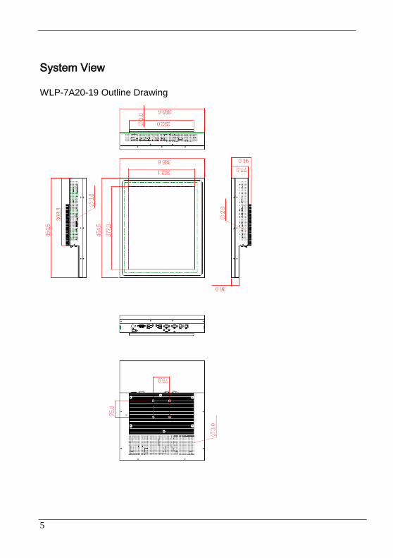
System View
WLP-7A20-19 Outline Drawing
6
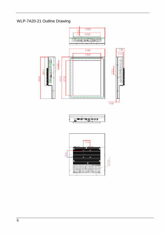
WLP-7A20-21 Outline Drawing
7
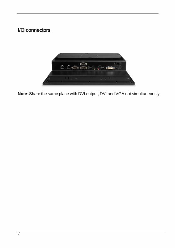
I/O connectors
Note: Share the same place with DVI output, DVI and VGA not simultaneously
8
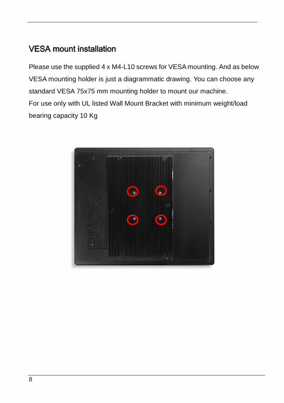
VESA mount installation
Please use the supplied 4 x M4-L10 screws for VESA mounting. And as below
VESA mounting holder is just a diagrammatic drawing. You can choose any
standard VESA 75x75 mm mounting holder to mount our machine.
For use only with UL listed Wall Mount Bracket with minimum weight/load
bearing capacity 10 Kg

9

10
Unpacking
After unpacking the shipping carton, you should find these standard items:
The WLP-7A20 Panel PC series
Accessory box including the followings:
– AC-DC adapter x 1
– AC power cord x 1
– Screws (M3x0.5PxL6) x 8
– Screws (M4x0.7PxL44) x 8
– CD-ROM for drivers, utility, user manual(in PDF format)
Inspect all the items. If any item is damaged or missing, notify your dealer immediately.

11
Getting Started
This chapter tells you how to set up the system.
12
Setting up the System
The following is a summary of the steps in setting up the system for use.
CAUTION: Make sure that power to the system and each of the devices to be connected is switched OFF before plugging in the connectors.
1. Make any required external connections such as the keyboard, and mouse.
2. Plug the appropriate end of the power cord into the power connector of the system. Then plug the other end of the power cord to an electrical outlet.
3. Press the power switch of the system to turn on the system’s power.
4. If necessary, run the BIOS SETUP program to configure the system (see Chapter 3).
5. Install the software drivers if necessary.
13
Installing System Software
Recent releases of operating systems from major vendors include setup
programs, which load automatically and guide you through hard disk
preparation and operating system installation. The guidelines below will
help you determine the steps necessary to install your operating system on
the Panel PC hard drive.
NOTE: Some distributors and system integrators may have already
pre-installed system software prior to shipment of your Panel PC.
Installing software requires an installed HDD. Software can be loaded in the
WLP-7A20 Panel PC using any of below methods:
Method 1: Use the Ethernet
You can use the Ethernet port to download software from the net to the
HDD that has been pre-installed in WLP-7A20 Panel PC
Method 2: Use the COM Port
By connecting another PC to the WLP-7A20 Panel PC with an
appropriate cable, you can use transmission software to transmit
Operation System Software to the HDD that has been pre-installed in the
WLP-7A20 Panel PC.
Method 3: Use a External CD-ROM
In order to boot up system from USB-CD/DVD drive, please connect
USB-CD/DVD drive, turn on computer power, keep on pressing “F11”
key, go into BIOS quick boot menu, select “USB-CD ROM”, WAIT FOR
20 SECONDS, then press enter, system OS will boot up from
USB-CD/DVD drive directly

14
Then you can use the external CD-ROM to transmit the software to the
HDD that has been pre-installed in the WLP-7A20 Panel PC

15
Installing the Drivers
After installing your system software, you will be able to set up the LAN,
VGA, Audio and USB functions. All drivers are stored in a CD disc, which
can be found in your accessory pack.
The various drivers and utilities in the disc have their own text files that help
users install the drivers and understand their functions.
Follow the sequence below to install the drivers:
Step 1 – Install Intel® INF Driver
Step 2 – Install Intel® VGA Driver
Step 3 – Install Intel® LAN Driver
Step 4 – Install Audio Driver
Step 1 – Install Intel® INF Driver
1. Open fie of chipset
2. Click on the setup.exe
3. Follow the instructions that the window shows
4. The system will help you install the driver automatically
5. Reboot system
Step 2 –Install Intel® VGA Driver
1. Open fie of VGA
2. Select the OS folder your system is
3. Click on the .exe file located in the OS folder
4. Follow the instructions that the window shows
5. The system will help you install the driver automatically
6. Reboot system
Step 3 – Install Intel® LAN Driver
1. Open fie of LAN
16
2. Click on the setup.exe
3. Follow the instructions that the window shows
4. The system will help you install the driver automatically
5. Reboot system
Step 4 – Install Audio Driver
1. Open fie of LAN
2. Click on the setup.exe
3. Follow the instructions that the window shows
4. The system will help you install the driver automatically
5. Reboot system
17
BIOS Setup Information
BIOS Introduction
The AMI BIOS (Basic Input / Output System) installed in your computer
system’s ROM supports Intel processors. The BIOS provides critical
low-level support for a standard device such as disk drives, serial ports and
parallel ports. It also adds virus and password protection as well as special
support for detailed fine-tuning of the chipset controlling the entire system.
BIOS Setup
The AMI BIOS provides a Setup utility program for specifying the system
configurations and settings. The BIOS ROM of the system stores the Setup
utility. When you turn on the computer, the AMI BIOS is immediately
activated. Pressing the <Del> key immediately allows you to enter the Setup
utility. If you are a little bit late pressing the <Del> key, POST (Power On Self
Test) will continue with its test routines, thus preventing you from invoking the
Setup. If you still wish to enter Setup, restart the system by pressing
the ”Reset” button or simultaneously pressing the <Ctrl>, <Alt> and <Delete>
keys. You can also restart by turning the system Off and back On again. The
following message will appear on the screen:
Press <DEL> to Enter Setup
In general, you press the arrow keys to highlight items, <Enter> to select,
the <PgUp> and <PgDn> keys to change entries, <F1> for help and <Esc>
to quit.
When you enter the Setup utility, the Main Menu screen will appear on the
screen. The Main Menu allows you to select from various setup functions
and exit choices.

18
Main
This section provides information on the BIOS information, Memory
information, and Battery information
System Date
Set the system date. Use the <Tab> key to switch between data elements.
System Time
Set the system time. Use the <Tab> key to switch between time elements.

19
Advanced
Launch OpROM Support
Launch PXE OpROM
Enables or disables Boot Option for Legacy Network Devices.
Launch Storage OpROM
Enables or disables Boot Option for Legacy Mass Storage Devices with
Option ROM.
PCI Subsystem Settings
PCI ROM Priority
In Case of multiple Option ROMs (Legacy and EFI Compatible),
specifies what PCI Option ROM to launch.
PCI Latency Timer
Value to be programmed into PCI Latency Timer Register.
VGA Palette Snoop

20
Enables or disables VGA Palette Registers Snooping.
PERR# Generation
Enables or Disables PCI Device to Generate PERR#.
SERR# Generation
Enables or Disables PCI Device to Generate SERR#.
Relaxed Ordering
Enables or Disables PCI Express Device Relaxed Ordering.
Extended Tag
If ENABLED allows Device to use 8-bit Tag field as a requester.
No Snoop
Enables or Disables PCI Express Device No Snoop option.
Maximum Payload
Set Maximum Payload of PCI Express Device or allow System BIOS to
select the value
Maximum Read Request
Set Maximum Read Request Size of PCI Express Device or allow
System BIOS to select the value.
ASPM Support
Set the ASPM Level: Force L0 – Force all links to L0 State : AUTO –
BIOS auto configure : DISABLE – Disables ASPM.
Extended Synch
If ENABLED allows generation of Extended Synchronization patterns.
ACPI Settings
Enables ACPI Auto Conf
Enables or Disables BIOS ACPI Auto Configuration.
Enable Hibernation
Enables or Disables System ability to Hibernate (OS/S4 Sleep State).
This option may be not effective with some OS.

21
ACPI Sleep State
Select the highest ACPI sleep state the system will enter, when the
SUSPEND button is pressed.
S5 RTC Wake Settings
Wake System with Fixed Time
Enables or disables system wake on alarm event. When enabled, the
system will wake on the time specified.
Wake system with Dynamic Time
Enables or disables system wake on alarm event. When enabled, the
system will wake on the current time+Increase minute(s).
CPU Configuration
Hyper-Threading
Enabled for Windows XP and Linux (OS optimized for Hyper-Threading
Technology) and Disabled for other OS (OS optimized for
Hyper-Threading Technology)
Core-Multi Processing
Enable or Disable Core-Multi Processing mode.
Execute Disable Bit
XD can prevent certain classes of malicious buffer overflow attacks
when combined with a supporting OS (Windows Server 2003 SP1,
Windows XP SP2, SuSE Linux 9.2, RedHat Enterprise 3 Update 3.)
Limit CPUID Maximum
Disabled for Windows XP.
IDE Configuration
ATA or IDE Configuration
Select ATA or IDE configuration.
Configure SATA AS
Select a configuration for SATA controller.

22
HDD Acoustic Power Ma
Option to enable or disable HDD Acoustic Power Management.
DiPM
Option to enable or disable DiPM
Intel IGD SWSCI OpRegion
DVMT Mode Select
Selects DVMT Mode used by Internal Graphics Device.
DVMT/FIXED Memory
Selects DVMT/FIXED Mode Memory size used by Internal Graphics
Device.
IGD – Boot Type
Select the Video Device which will be activated during POST. This has
no effect if external graphics present.
LCD Panel Type
Select LCD panel used by Internal Graphics Device by selecting the
appropriate setup item.
Panel Scaling
Select the LCD panel scaling option used by the Internal Graphics
Device.
GMCH BLC Control
Back Light Control Setting
BIA Control
Spread Spectrum clock
>>Hardware: Spread is controlled by chip;
>>Software: Spread is controlled by BIOS.
TV1 Standard
TV2 Standard
Active LFP

23
Select the Active LFP Configuration.
No LVDS:VBIOS does not enable LVDS.
INT-LVDS:VBIOS enables LVDS driver by Integrated encoder.
SDV0 LVDS:VBIOS enables LVDS driver by SDV0.
USB Configuration
Legacy USB Support
Allows USB devices to be used in MS-DOS.
EHCI Hand-off
This is a workaround for 0Ses without EHCI hand-off support. The
EHCI ownership change should be claimed by EHCI driver.
USB transfer time-out
The time-out value for Control, Bulk, and Interrupt transfers.
Device reset time-out
USB mass storage device Start Unit command time-out.
Device power-up delay
Maximum time the device will take before it properly reports itself to the
HOST Controller.
‘Auto’ uses default value: for a Root port it is 100 ms, for a Hub port the
delay is taken from Hub descriptor.
F71869 Super IO Configuration
Serial Port 0 Configuration
Set Parameters of Serial Port 0 (COM A).
Serial Port 1 Configuration
Set Parameters of Serial Port 1 (COM B).
F71869 H/W Monitor
Monitor hardware status
Second Super IO Configuration
Serial Port 1 Configuration

24
Set Parameters of Serial Port 1 (COM C).
Serial Port 2 Configuration
Set Parameters of Serial Port 2 (COM D).
Serial Port 3 Configuration
Set Parameters of Serial Port 3 (COM E).
Serial Port 4 Configuration
Set Parameters of Serial Port 4 (COM F).
Serial Port Console Redirection
Serial Port Console Redirection.
Chipset
Host Bridge/South Bridge
This screen provides information on Host Bridge/South Bridge parameters.
25
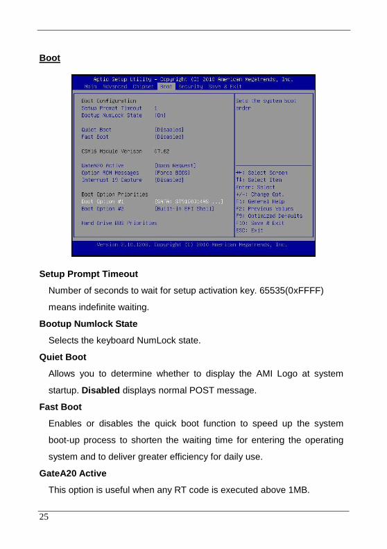
Boot
Setup Prompt Timeout
Number of seconds to wait for setup activation key. 65535(0xFFFF)
means indefinite waiting.
Bootup Numlock State
Selects the keyboard NumLock state.
Quiet Boot
Allows you to determine whether to display the AMI Logo at system
startup. Disabled displays normal POST message.
Fast Boot
Enables or disables the quick boot function to speed up the system
boot-up process to shorten the waiting time for entering the operating
system and to deliver greater efficiency for daily use.
GateA20 Active
This option is useful when any RT code is executed above 1MB.

26
Upon Request GA20 can be disabled using BIOS services. (Default)
Always Do not allow disabling GA20.
Option ROM Messages
Sets display made for option ROM.
Interrupt 19 Capture
Enables or disables Option ROMs to Trap Int 19.
Boot Option Priorities
Specifies the sequence of loading the operating system from the installed
hard drives.
Security
Enables or disables the security chip. It is recommended that you use this
function with the Administrator/User password.
27
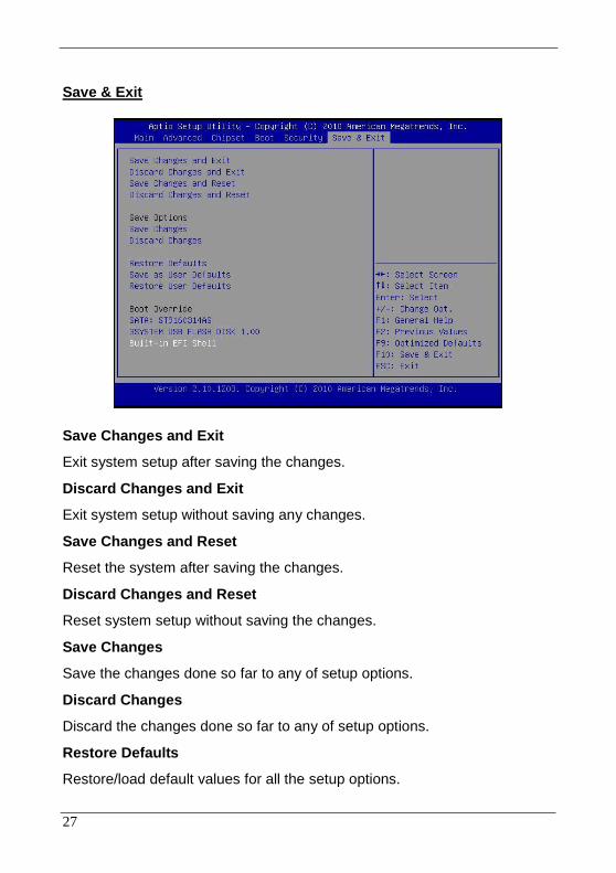
Save & Exit
Save Changes and Exit
Exit system setup after saving the changes.
Discard Changes and Exit
Exit system setup without saving any changes.
Save Changes and Reset
Reset the system after saving the changes.
Discard Changes and Reset
Reset system setup without saving the changes.
Save Changes
Save the changes done so far to any of setup options.
Discard Changes
Discard the changes done so far to any of setup options.
Restore Defaults
Restore/load default values for all the setup options.

28
Save as User Defaults
Save the changes done so far as User Defaults.
Restore User Defaults
Restore the User Defaults to all the setup options.
EFIGUI_FLASH
Press <Enter> to execute the simple EFI GUI Flash Program.
29
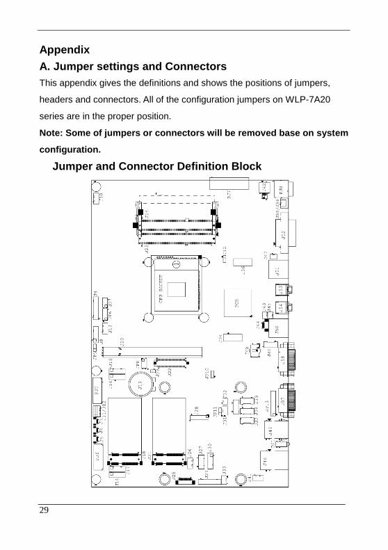
Appendix
A. Jumper settings and Connectors
This appendix gives the definitions and shows the positions of jumpers,
headers and connectors. All of the configuration jumpers on WLP-7A20
series are in the proper position.
Note: Some of jumpers or connectors will be removed base on system
configuration.
Jumper and Connector Definition Block

30
JP5 –Backlight Adjust
Description Jumper Setting
analog Inverter
1-2 (default)
PWM Inverter 2-3

31
JP6 – Touch Panel Wire Selection
Description Jumper Setting
4 wire 1-2, 3-4, 5-6, 7-8, 9-10
5 wire 3-4, 5-6, 7-8, 9-10 (default)
8 wire 1-2

32
JP7 – Touch Panel Type Selection
Description Jumper Setting
3M type 1-2, 3-4 (default)
ELO type 5-6,7-8

33
JP8– Panel Power Selection
Description Jumper Setting
+5VS (for 17"/19"/21.5”) 1-2,3-4 (default)
+3.3VS (for 10"/12"/15") 5-6,7-8

34
JP9 –TPM Settings
Description Jumper Setting
Clear ME RTC registers 1-2
Keep ME RTC registers
OPEN (default)
35
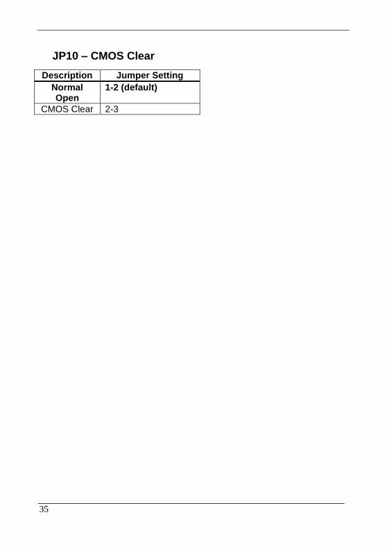
JP10 – CMOS Clear
Description Jumper Setting
Normal Open
1-2 (default)
CMOS Clear 2-3
36
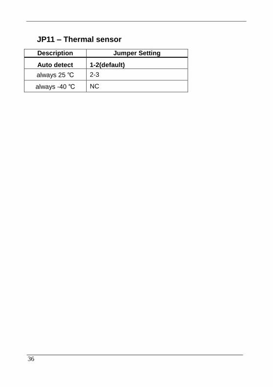
JP11 – Thermal sensor
Description Jumper Setting
Auto detect 1-2(default)
always 25 ℃ 2-3
always -40 ℃ NC

37
JP12 – SATA or SATA DOM Selection
Description Jumper Setting
SATA DOM 1-2 ---power +5V
SATA 2-3(default)--- GND

38
JP13 – COM1 Function Selection
Description Jumper Setting
RS-232 5-6, 9-11, 10-12, 15-17, 16-18(default)
RS-422 3-4, 7-9, 8-10, 13-15, 14-16, 21-22
RS-485 1-2, 7-9, 8-10, 19-20

39
Connector Definition
40
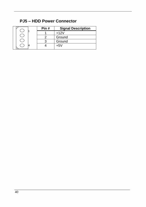
PJ5 – HDD Power Connector
1
4
Pin # Signal Description
1 +12V
2 Ground
3 Ground
4 +5V
41
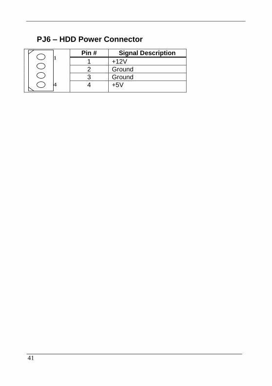
PJ6 – HDD Power Connector
1
4
Pin # Signal Description
1 +12V
2 Ground
3 Ground
4 +5V

42
PJ7 – Battery Connector
Pin1
Pin # Signal Description
1 BATT+ 2 BATT+ 3 BATT+ 4 BAT_T 5 BAT_C 6 BAT_D 7 BATT_EN# 8 BATT- 9 BATT- 10 BATT-
43
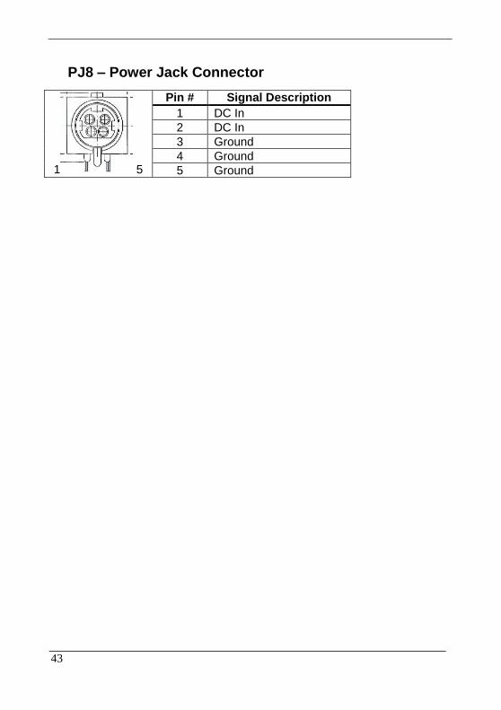
PJ8 – Power Jack Connector
1 5
Pin # Signal Description
1 DC In
2 DC In
3 Ground
4 Ground
5 Ground
44
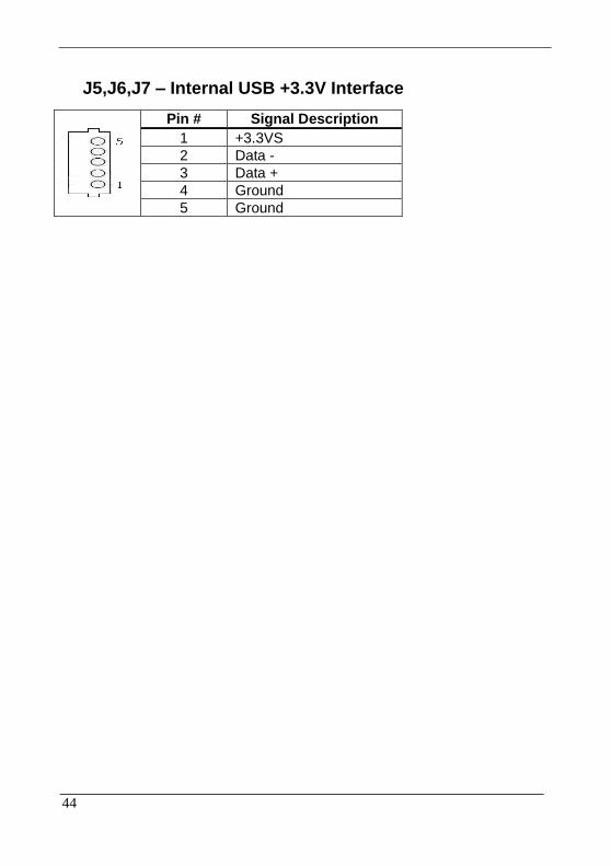
J5,J6,J7 – Internal USB +3.3V Interface
Pin # Signal Description
1 +3.3VS
2 Data -
3 Data +
4 Ground
5 Ground

45
J8 – LCD Inverter Interface
6 1
Pin # Signal Description
1 +12V
2 +12V
3 Backlight Adjust
4 Backlight Enable
5 Ground
6 Ground

46
J9 –Resistor Touch Panel Interface
1
9
Pin # Signal Description
8-wire 4-wire 5-wire
1 UL(X+) UL(X+) UL(X+)
2 UR(Y+) UR(Y+) UR(Y+)
3 N/A N/A PRCBE
4 LR(X-) LR(X-) LR(X-)
5 LL(Y-) LL(Y-) LL(Y-)
6 X+_DRIVE N/A N/A
7 Y+_DRIVE N/A N/A
8 X-_DRIVE N/A N/A
9 Y-_DRIVE N/A N/A
47
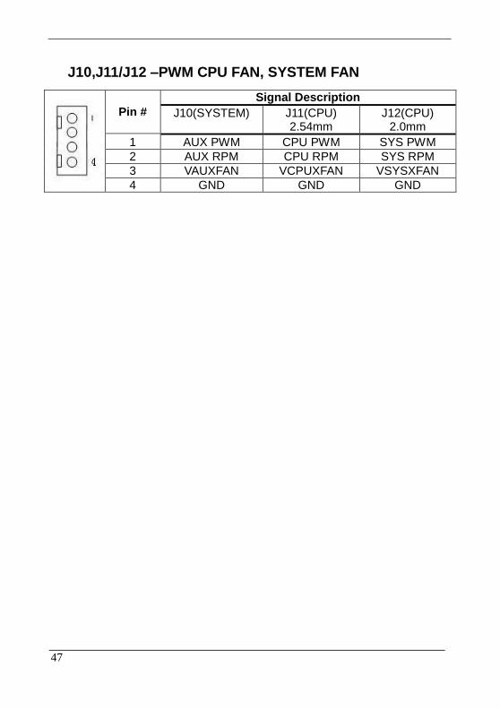
J10,J11/J12 –PWM CPU FAN, SYSTEM FAN
Pin #
Signal Description
J10(SYSTEM) J11(CPU) 2.54mm
J12(CPU) 2.0mm
1 AUX PWM CPU PWM SYS PWM
2 AUX RPM CPU RPM SYS RPM
3 VAUXFAN VCPUXFAN VSYSXFAN
4 GND GND GND
48
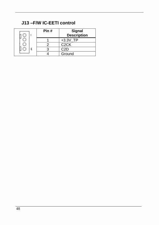
J13 –F/W IC-EETI control
Pin # Signal Description
1 +3.3V_TP
2 C2CK
3 C2D
4 Ground
49
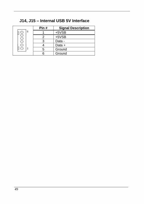
J14, J15 – Internal USB 5V Interface
Pin # Signal Description
1 +5VSB
2 +5VSB
3 Data -
4 Data +
5 Ground
6 Ground
50
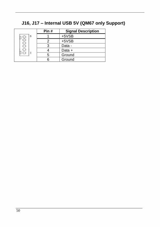
J16, J17 – Internal USB 5V (QM67 only Support)
Pin # Signal Description
1 +5VSB
2 +5VSB
3 Data -
4 Data +
5 Ground
6 Ground
51
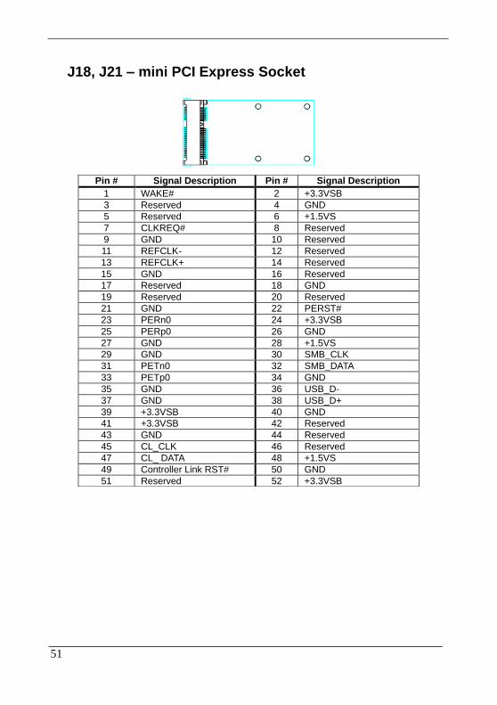
J18, J21 – mini PCI Express Socket
Pin # Signal Description Pin # Signal Description
1 WAKE# 2 +3.3VSB
3 Reserved 4 GND
5 Reserved 6 +1.5VS
7 CLKREQ# 8 Reserved
9 GND 10 Reserved
11 REFCLK- 12 Reserved
13 REFCLK+ 14 Reserved
15 GND 16 Reserved
17 Reserved 18 GND
19 Reserved 20 Reserved
21 GND 22 PERST#
23 PERn0 24 +3.3VSB
25 PERp0 26 GND
27 GND 28 +1.5VS
29 GND 30 SMB_CLK
31 PETn0 32 SMB_DATA
33 PETp0 34 GND
35 GND 36 USB_D-
37 GND 38 USB_D+
39 +3.3VSB 40 GND
41 +3.3VSB 42 Reserved
43 GND 44 Reserved
45 CL_CLK 46 Reserved
47 CL_ DATA 48 +1.5VS
49 Controller Link RST# 50 GND
51 Reserved 52 +3.3VSB
52
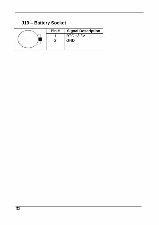
J19 – Battery Socket
Pin # Signal Description
1 RTC +3.3V
2 GND

53
J20 –Standard PCIE X16 Slot Interface
Pin #
Side B Side A Pin #
Side B Side A
1 +12V PRSNT1# 42 PETn6 GND
2 +12V +12V 43 GND PERp6
3 +12V +12V 44 GND PERn6
4 GND GND 45 PETp7 GND
5 SMCLK PCIE_TXN6 46 PETn7 GND
6 SMDAT PCIE_TXP6 47 GND PERp7
7 GND PCIE_RXN6 48 Reserved PERn7
8 +3.3V PCIE_RXP6 49 GND GND
9 Reserved +3.3V 50 PETp8 Reserved
10 +3.3V +3.3V 51 PETn8 GND
11 WAKE# PERST# 52 GND PERp8
12 Reserved GND 53 GND PERn8
13 GND PCIEx16_CLK+ 54 PETp9 GND
14 PETp0 PCIEx16_CLK- 55 PETn9 GND
15 PETn0 GND 56 GND PERp9
16 GND PERp0 57 GND PERn9
17 Reserved PERn0 58 PETp10 GND
18 GND GND 59 PETn10 GND
19 PETp1 Reserved 60 GND PERp10
20 PETn1 GND 61 GND PERn10
21 GND PERp1 62 PETp11 GND
22 GND PERn1 63 PETn11 GND
23 PETp2 GND 64 GND PERp11
24 PETn2 GND 65 GND PERn11
25 GND PERp2 66 PETp12 GND
26 GND PERn2 67 PETn12 GND
27 PETp3 GND 68 GND PERp12
28 PETn3 GND 69 GND PERn12
29 GND PERp3 70 PETp13 GND
30 PCIEx1_CLK+ PERn3 71 PETn13 GND
31 PCIEx1_CLK- GND 72 GND PERp13
32 GND Reserved 73 GND PERn13
33 PETp4 Reserved 74 PETp14 GND
34 PETn4 GND 75 PETn14 GND

54
35 GND PERp4 76 GND PERp14
36 GND PERn4 77 GND PERn14
37 PETp5 GND 78 PETp15 GND
38 PETn5 GND 79 PETn15 GND
39 GND PERp5 80 GND PERp15
40 GND PERn5 81 Reserved PERn15
41 PETp6 GND 82 PCICLK_33M GND

55
J22 – LVDS Interface
Pin # Signal Description Pin # Signal Description
1 +LCD (+5V/ +3.3V) 2 +LCD (+5V/ +3.3V)
3 +LCD (+5V/ +3.3V) 4 +LCD (+5V/ +3.3V)
5 Ground 6 Ground
7 Ground 8 Ground
9 A_RxIn0- 10 B_RxIn0-
11 A_RxIn0+ 12 B_RxIn0+
13 Ground 14 Ground
15 A_RxIn1- 16 B_RxIn1-
17 A_RxIn1+ 18 B_RxIn1+
19 Ground 20 Ground
21 A_RxIn2- 22 B_RxIn2-
23 A_RxIn2+ 24 B_RxIn2+
25 Ground 26 Ground
27 A_CKIN- 28 B_CKIN-
29 A_CKIN+ 30 B_CKIN+
31 Ground 32 Ground
33 A_RxIn3- 34 B_RxIn3-
35 A_RxIn3+ 36 B_RxIn3+
37 Ground 38 Ground
39 Ground 40 Ground
56
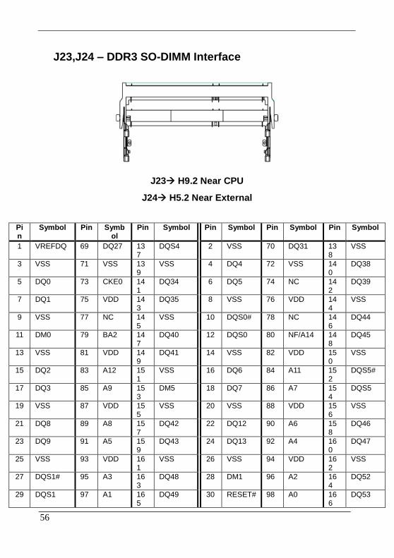
J23,J24 – DDR3 SO-DIMM Interface
J23 H9.2 Near CPU
J24 H5.2 Near External
Pin
Symbol Pin Symbol
Pin Symbol Pin Symbol Pin Symbol Pin Symbol
1 VREFDQ 69 DQ27 137
DQS4 2 VSS 70 DQ31 138
VSS
3 VSS 71 VSS 139
VSS 4 DQ4 72 VSS 140
DQ38
5 DQ0 73 CKE0 141
DQ34 6 DQ5 74 NC 142
DQ39
7 DQ1 75 VDD 143
DQ35 8 VSS 76 VDD 144
VSS
9 VSS 77 NC 145
VSS 10 DQS0# 78 NC 146
DQ44
11 DM0 79 BA2 147
DQ40 12 DQS0 80 NF/A14 148
DQ45
13 VSS 81 VDD 149
DQ41 14 VSS 82 VDD 150
VSS
15 DQ2 83 A12 151
VSS 16 DQ6 84 A11 152
DQS5#
17 DQ3 85 A9 153
DM5 18 DQ7 86 A7 154
DQS5
19 VSS 87 VDD 155
VSS 20 VSS 88 VDD 156
VSS
21 DQ8 89 A8 157
DQ42 22 DQ12 90 A6 158
DQ46
23 DQ9 91 A5 159
DQ43 24 DQ13 92 A4 160
DQ47
25 VSS 93 VDD 161
VSS 26 VSS 94 VDD 162
VSS
27 DQS1# 95 A3 163
DQ48 28 DM1 96 A2 164
DQ52
29 DQS1 97 A1 165
DQ49 30 RESET# 98 A0 166
DQ53

57
31 VSS 99 VDD 167
VSS 32 VSS 100
VDD 168
VSS
33 DQ10 101
CK0 169
DQS6# 34 DQ14 102
CK1 170
DM6
35 DQ11 103
CK0# 171
DQS6 36 DQ15 104
CK1# 172
VSS
37 VSS 105
VDD 173
VSS 38 VSS 106
VDD 174
DQ54
39 DQ16 107
A10 175
DQ50 40 DQ20 108
BA1 176
DQ55
41 DQ17 109
BA0 177
DQ51 42 DQ21 110
RAS# 178
VSS
43 VSS 111 VDD 179
VSS 44 VSS 112
VDD 180
DQ60
45 DQS2# 113 WE# 181
DQ56 46 DM2 114
S0# 182
DQ61
47 DQS2 115 CAS# 183
DQ57 48 VSS 116
ODT0 184
VSS
49 VSS 117 VDD 185
VSS 50 DQ22 118
VDD 186
DQS7#
51 DQ18 119 A13 187
DM7 52 DQ23 120
NC 188
DQS7
53 DQ19 121
NC 189
VSS 54 VSS 122
NC 190
VSS
55 VSS 123
VDD 191
DQ58 56 DQ28 124
VDD 192
DQ62
57 DQ24 125
NC 193
DQ59 58 DQ29 126
VREFCA
194
DQ63
59 DQ25 127
VSS 195
VSS 60 VSS 128
VSS 196
VSS
61 VSS 129
DQ32 197
SA0 62 DQ3# 130
DQ36 198
EVENT#
63 DM3 131
DQ33 199
VDDSPD 64 DQ3 132
DQ37 200
SDA
65 VSS 133
VSS 201
SA1 66 VSS 134
VSS 202
SCL
67 DQ26 135
DQS4#
203
VTT 68 DQ30 136
DM4 204
VTT

58
J25 – CAP Front Bezel Button Connector ( For WMP-226/227)
Pin # Signal Description
1 +3.3V
2 +3.3V
3 KP_SCL
4 KP_SDA
5 HEATER_LED#
6 KP_INT#
7 SATA_LED#
8 Ground
9 Ground
1
9

59
J26 – SDP (EC Simple Debug Port)
Pin # Signal Description
1 +5V
2 P80_DAT
3 P80_CLK
4 Ground

60
J27 – EC JTAG
Pin # Signal Description Pin # Signal Description
1 EC_TRST# 2 +3.3V
3 EC_TMS 4 EC_RDY#
5 EC_TDI 6 GND
7 EC_TCK 8 GND
9 EC_TDO 10 GND

61
J28 –TPM / ID-394
Pin #
Signal Description Pin # Signal Description
1 LPC AD0 2 PCI reset
3 LPC AD1 4 SERIRQ
5 LPC AD2 6 +3.3V
7 LPC AD3 8 +5V
9 LPC Frame 10 PCI CLKRUN
11 Debug CLK 12 SMB CLK
13 GND 14 SMB DATA
15 SUS_STAT# 16 +3.3V

62
J29 – Front Bezel Button Connector
Pin # Signal Description
1 Power Button
2 +3.3V
3 Sound Volume Up
4 Sound Volume Down
5 Ground
6 LCD BackLight Up
7 LCD BackLight Down
8 Touch Screen Forbid
9 LCD BackLight ON/OFF
1
9
63
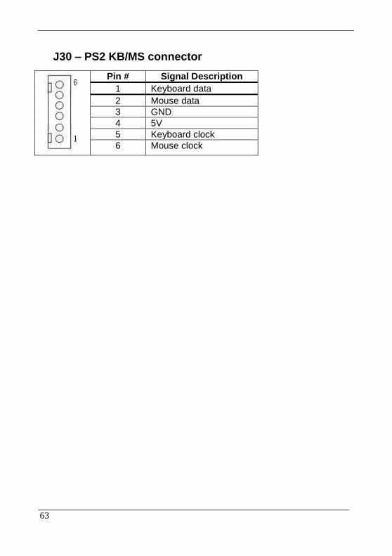
J30 – PS2 KB/MS connector
Pin # Signal Description
1 Keyboard data
2 Mouse data
3 GND
4 5V
5 Keyboard clock
6 Mouse clock
64
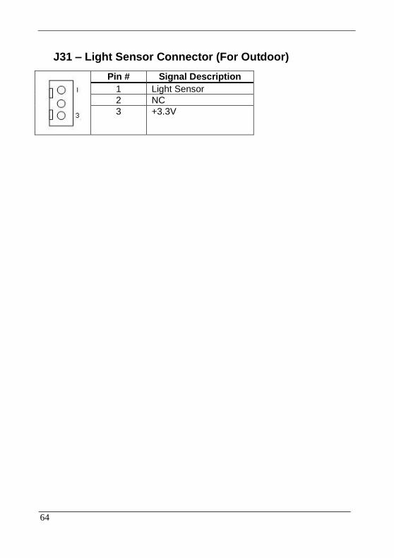
J31 – Light Sensor Connector (For Outdoor)
Pin # Signal Description
1 Light Sensor
2 NC
3 +3.3V
65
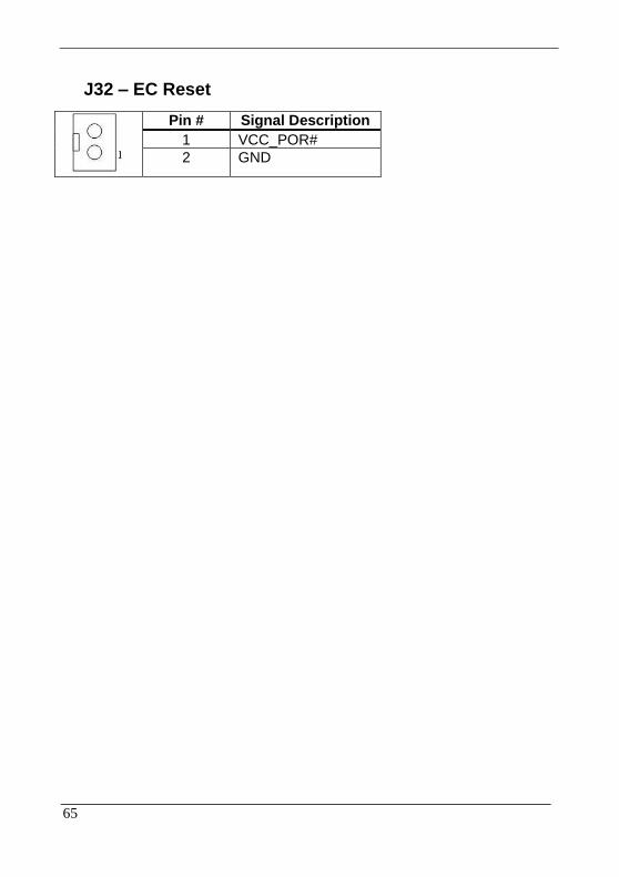
J32 – EC Reset
Pin # Signal Description
1 VCC_POR#
2 GND

66
J33 – HEATER, CLEAR ME LED INDICATE
Pin # Signal Description
1 +3.3V_UC
2 HEATER_LED#
3 KEYLOCK_LED#
67
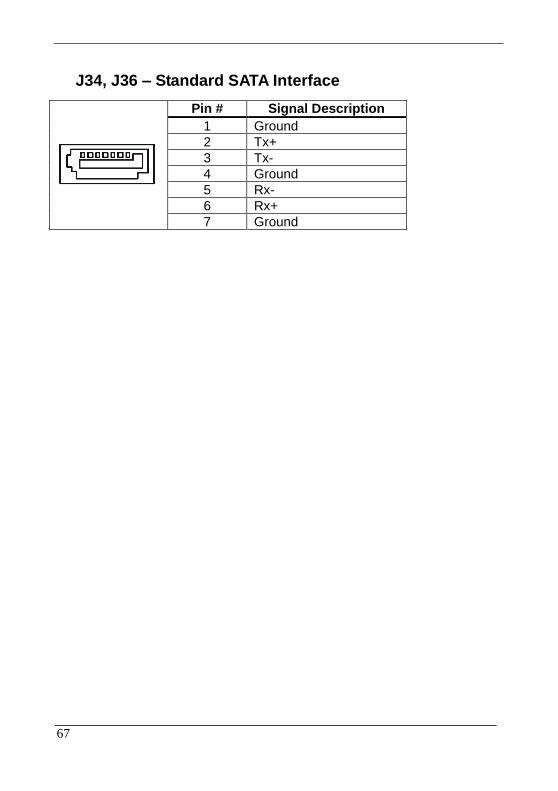
J34, J36 – Standard SATA Interface
Pin # Signal Description
1 Ground
2 Tx+
3 Tx-
4 Ground
5 Rx-
6 Rx+
7 Ground

68
J35 – RS-232 TTL Connector
Pin # Signal Description
Pin # Signal Description
1 DCD# 2 DSR#
3 SIN 4 RTS#
5 SOUT 6 CTS#
7 DTR# 8 RI#
9 GND 10 +5VS
69
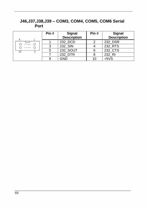
J46,J37,J38,J39 – COM3, COM4, COM5, COM6 Serial Port
Pin # Signal Description
Pin # Signal Description
1 232_DCD 2 232_DSR
3 232_SIN 4 232_RTS
5 232_SOUT 6 232_CTS
7 232_DTR 8 232_RI
9 GND 10 +5VS
70
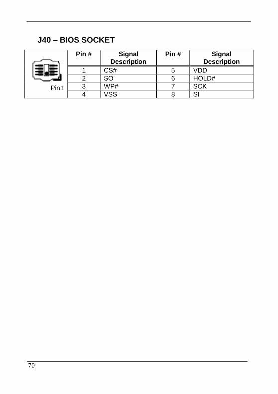
J40 – BIOS SOCKET
Pin1
Pin # Signal Description
Pin # Signal Description
1 CS# 5 VDD
2 SO 6 HOLD#
3 WP# 7 SCK
4 VSS 8 SI
71
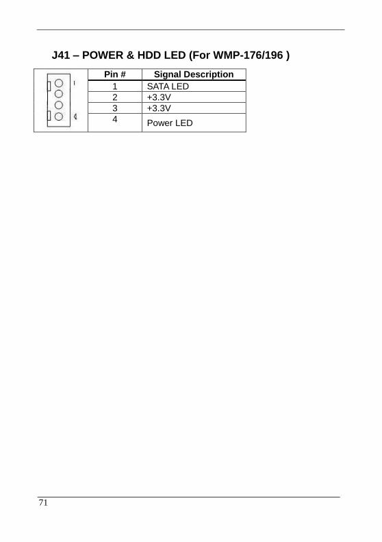
J41 – POWER & HDD LED (For WMP-176/196 )
Pin # Signal Description
1 SATA LED
2 +3.3V
3 +3.3V
4 Power LED

72
J42 – ATX 12V Connect (For Heater Power)
Pin # Signal Description
1 +12V
2 +12V
3 Ground
4 Ground

73
J43 , J45 – Passive Speaker Connect
J43(Right Channel) J45(Left Channel)
Pin # Signal Description Pin # Signal Description
1 AMP. Out + 1 AMP. Out +
2 AMP. Out - 2 AMP Out -
74
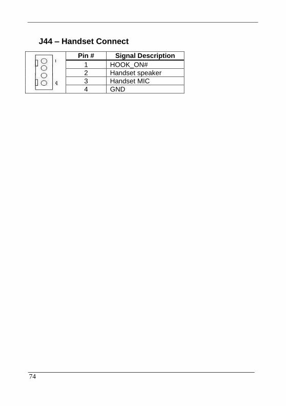
J44 – Handset Connect
Pin # Signal Description
1 HOOK_ON#
2 Handset speaker
3 Handset MIC
4 GND

75
J47 – Power Switch connect
Pin # Signal Description
1 Power ON
2 GND

76
J48, J49 – Ethernet Port
Pin # Signal Description
1 Data0+
2 Data0-
3 Data1+
4 Data2+
5 Data2-
6 Data1-
7 Data3+
8 Data3-
77
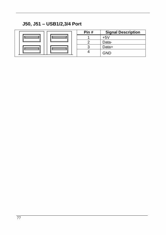
J50, J51 – USB1/2,3/4 Port
Pin # Signal Description
1 +5V
2 Data-
3 Data+
4 GND

78
J52 – DVI-I Interface
Pin # Signal Description Pin # Signal Description
1 TMDS Data2- 2 TMDS Data2+
3 TMDS Data2 shield 4 NC
5 NC 6 DDC Clock
7 DDC Data 8 Analog VSYNC
9 TMDS Data1- 10 TMDS Data1+
11 TMDS Data1 Shield 12 NC
13 NC 14 +5V
15 GND 16 Hot Plug Detect
17 TMDS Data0- 18 TMDS Data0+
19 TMDS Data0 Shield 20 NC
21 NC 22 TMDS Clock Shield
23 TMDS Clock+ 24 TMDS Clock-
C1 Analog Red C2 Analog Green
C3 Analog Blue C4 Analog HSYNC
C5 GND C6 GND

79
J53,J54 – Audio Connector
Pin # Signal Description
J53 Microphone (stereo) Pink
J54 Line Out (stereo) Green
80
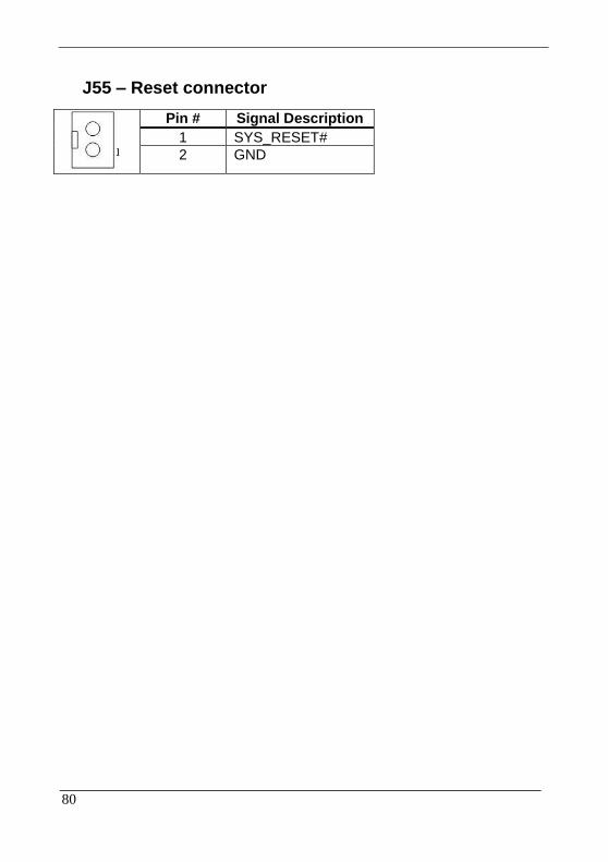
J55 – Reset connector
Pin # Signal Description
1 SYS_RESET#
2 GND

81
J56 – Reset Button
Pin # Signal Description
1 SYS_RESET#
2 GND

82
J57 – COM1 Connector
Pin # Signal Description
RS-232 RS-422 RS-485
1 Carrier Detect Transmit Data - Transmit Data -
2 Receive Data Transmit Data + Transmit Data +
3 Transmit Data Receive Data + NC
4 Data Terminal Ready
Receive Data - NC
5 Ground NC NC
6 Data Set Ready NC NC
7 Request to Send NC NC
8 Clear to Send NC NC
9 Ring Indicator NC NC
83
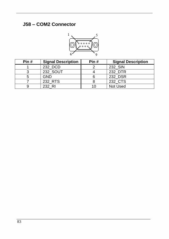
J58 – COM2 Connector
Pin # Signal Description Pin # Signal Description
1 232_DCD 2 232_SIN
3 232_SOUT 4 232_DTR
5 GND 6 232_DSR
7 232_RTS 8 232_CTS
9 232_RI 10 Not Used
84
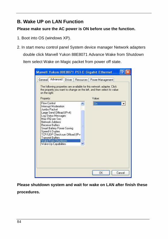
B. Wake UP on LAN Function
Please make sure the AC power is ON before use the function.
1. Boot into OS (windows XP).
2. In start menu control panel System device manager Network adapters
double click Marvell Yukon 88E8071 Advance Wake from Shutdown
Item select Wake on Magic packet from power off state.
Please shutdown system and wait for wake on LAN after finish these
procedures.