wood - gfc.state.ga.us · chapter 1 heating your home with wood b oth fireplaces and wood heaters...
TRANSCRIPT

Atlanta, Georgia August 1987 First Edition
Wood Heating - Safety, Savings and Comfort
Governor's Off i ce of Energy Resources Georgia Forestry Commission

Credits - Project Director Dennis B. Creech
Principal Author Thomas McGowan, PE
Editors Carol Aton Dennis B. Creech Jeffrey S. Tiller, PE Rene Dziejowski
Graphic Artists Walton Harris Dirk Hays
Word Processing/ Research Gayle Coppock Lisa Lawes
List of Contributors The Southface Energy Institute wishes to
thank the following contributors to this woodstove publication:
J. Fred Allen, Georgia Forestry Commis- sion; Macon, GA Jerry Bartenfeld, The Crabapple General
Store; Alpharetta, GA Richard L. Best, NFPA; Batterymarch
Park, MA Carter Keithley, Wood Heating Appliance;
Washington, D.C. Tommy Loggins, Georgia Forestry Com-
mission; Macon, GA Richard A. Oliver, Georgia Specialties;
Roswell, GA Jay W. Shelton, Shelton Energy Research;
Santa Fe, NM William Warr, Nova Wood Heat; Great
Falls, VA
For additional copies of this publication, or other energy information, please contact:
Governor's Otrrce of Energy Resources 270 Washington St., NW Suite 615 Atlanta, GA 30334 (404) 656-5176
This publication was prepared under contract to the Governor's Office of Energy Resources by the South- face Energy Institute. Southface may be reached at:
Southface Energy Institute, Inc. 158 Moreland Avenue, SE/ P.O. Box 5506 Atlanta, GA 30307 (404) 525-7657
Disclaimer This publication was prepared with the support of
the U.S. Department of Energy grant numbers DE- FG44-80CS69091 and DE-FG44-77CS60212. However, any opinions, findings, conclusions, or rec- ommendations expressed herein are those of the author(s) and do not necessarilyreflect the views of the Department of Energy.
This manual was prepared by the Southface Energy Institute on behalf of the Governor's Office of Energy Resources. Neither the State of Georgia, the South- face Energy Institute, nor their agents or employees:
(a) make any warranties or representations what- soever, either express or implied, as to the accuracy, completeness, or reliability of the information con- tained in the manual; or
(b) assume or accept any liability for the use of, or damages resulting from the use of, any information contained in this manual or for the completeness of the text.
While installation specifications in this manual have been taken from national sources, safety codes and standards are being revised. You should always check with your local safety and building code officials prior to installing a wood heater and have these officials in- spect the heater after it is installed.
This publication is based on materials from Safe and Warm Wood Heat, Third Edition, originally pre- pared for the Tennessee Valley Authority by the Geor- gia Institute of Technology in 1981.
Table of Contents
Foreword .................................................. i
INTRODUCTION .. Is Wood Heat for You? ........................... II CHAPTER 1 Heating Your Home with Wood ............ 1
Types of Wood Heaters ................................. 1 How a Wood Heater Works .................................. 2 Efficiency .............................................................. 2 Heater Placement .. Where and Why ................... 3
................................................... Design Features 4 .......................................................... Accessories 5
Size ........................................................................ 6 How to Select a Wood Heater for Your Home ..... 7
CHAPTER 2 Safe Chimney Design ............................ 8
Prefabricated Metal Chimneys ............................ 9 Chimneys Built with Masonry ............................ 1 1
....................................... Safety Do's and Don'ts 1 5
CHAPTER 3 Installing Your Wood Heater ............... 17
.................... Some Materials Burn, Some Don't 17 ......................... Clearances .. A Must for Safety 17
CHAPTER 4 Connecting the Wood Heater to the Chimney ......................................... 24
Venting Through a Wall ..................................... 25 Venting Into a Masonry Chimney ....................... 25 Venting Into a Fireplace Chimney ...................... 25 Type A Fireplace Conversions ........................... 26 Type B Fireplace Conversion ........................... 27 Fireplace Inserts ................................................. 28
CHAPTER 5 Operating Your Heater System ........... 29
Do It Safely .......................................................... 29 ..................................... An Ounce of Prevention 30
Oh No, It Smokes! ........................................ 30 ............................. Watch Out for Chimney Fires 31
CHAPTER 6 Cleaning Your Wood Heating System 32
................................................... Chimneys First 3 2 Then Stovepipes and Heaters ........................... 32
CHAPTER 7 ............................. Obtaining Firewood 34 ..................................... Get Your Money's Worth 34
Cutting Wood ...................................................... 35
CHAPTER 8 ................................ Burning the Wood 37
Wood Burns in Four Stages ............................... 38 Words on Wood .................................................. 38
.............................................. More on Creosote 39
CHAPTER 9 Emission Standards for Wood Heaters ................................................. 41
CHAPTER 10 Wood Stove Catalytic Combustors .... 42
....................................................... How It Works 42 .................................. How To Choose a Retrofit 43
....................... Getting the Most from a Catalyst 44
..................................... Keep the Catalyst Clean 44 Economics .......................................................... 45
CHAPTER 11 Furnaces. Boilers. Multi-fuel Appliances.
.......................... and Central Systems 46
CHAPTER 12 Fireplaces ............................................. 47
CHAPTER 13 Wood Heating for Mobile Homes ....... 49
Questions and Answers about Wood Heaters ................................................. 50
........ Reference List for Woodburners 52
...................... Wood Heating Checklist 54

Foreword
S ince 1973, escalating fuel prices have forced more and more Americans to rediscover wood as a
source of heat. Not only is wood a renewable resource in plentiful supply, it is also relatively cheap. In terms of heating capacity, it is estimated that a cord of hard- wood burned in an airtight heater will deliver as much heat as 160 to 170 gallons of No. 2 fuel oil, or 260 therms of natural gas, or 6300 kilowatt hours of electricity. With hardwood selling for less than $90 per cord in much of the United States, wood can offer substantial savings on heating costs.
The U.S. Bureau of the Census data for 1970 show that there were nearly 800,000 occupied housing units in the U.S. in which wood was used as the principal heating fuel. Of this number, almost one-third were lo- cated in the South Atlantic states.
In the early 1980's, a Gallup poll indicated that there were 5 million wood heaters in use in the U.S. The U.S. Environmental Protection Agency (EPA) has esti- mated that present wood heater use is 12 million, which is about 19 percent of all one- and two-family dwell- ings. Heater shipments averaged 2.2 million per year from 1981 to 1985, but have recently declined due to stabilized oil and gas prices and maturation of the wood heating market.
Georgia residences used about 1.6 million cords of fuelwood in 1986. During the first five decades of this century, fuelwood consumption had dropped sharply as oil, gas, and electricity were substituted for domes- tic heating and cooking. Recently, however, consider- able demand for fuelwood has developed in both rural and urban areas for primary and secondary heating.
For the most part, owners of woodburning heaters can anticipate many years of adequate fuel supplies. U.S. Department of Agriculture Forest Service data in- dicate the area of commercial forest in the U.S. to be about 488 million acres, an area which is expected to remain relatively stable into the 21st century.
As manufacturers continue their research and development, the use of wood heaters is likely to in- crease. Equipment and methods to enhance the per- formance of new or existing wood heaters are being developed. The use of catalytic combustors, baffles, and firebrick linings are proving significant in increas- ing efficiency and decreasing emissions in wood heaters. These innovations indicate that wood is pro- gressing as an important alternative energy source.

Is Wood Heat for You? F or decades, all Georgians used wood, burned in a
fireplace, to heat their homes. However, heating with a fireplace required large amounts of wood and work. Most of the heat escaped up the chimney and much of the house stayed uncomfortable. With the development of wood heaters (wood stoves, central furnaces, and fireplace inserts) more of the house could be heated with less wood.
throughout the year. Follow the energy conservation guidelines presented in the publications listed in the references at the end of this book.
How much a wood heater saves you depends on how much you would pay to heat your home without wood. Many homeowners save 50 percent or more on electric or gas costs for heating by using wood.
Today over 380,000 Georgia homes have wood heaters. Heating with wood can save you money, espe- cially if you have an economical source of firewood and rely on one of the more eficient wood heaters. Wood heat has other advantages, too. It can provide abackup during winter power outages as well as a warm conver- sation center where family and friends inevitably gather. Some people also enjoy the activity of cutting and splitting firewood and stoking the fire.
But there definitely is manual labor involved with wood heaters, and a fire-safe lifestyle is a must. Re- member that a wood heater installation is nearly per- manent, so if you rent or move every few years, the heater will probably remain behind. Adding a wood heater could also affect your homeowners insurance, and if the installation is not done properly, lessen the home's value.
Before switching to wood heat, consider the lifestyIe changes you will have to make. Are you willing to gather wood? Is a high, medium, or low heat setting sdEcient for you rather than the precise temperature control of conventional systems? Do you want the cheery warmth of a wood heater even if it means inter- mittent stoking of the fire, cleaning the flue, and emp- tying ashes?
If you're willing to accept these lifestyle changes and you have a low cost source of firewood and an efficient wood heater, then you should be able to save substan- tially on home heating costs. But remember, even with wood heating, you should adopt practical energy con- servation measures. By saving energy, you will save money and improve comfort levels in your home
INTRODUCTION Is Wood Heat for You?

CHAPTER 1 Heating Your Home with Wood
B oth fireplaces and wood heaters are space heaters. They primarily radiate heat to people and objects
close by. To a lesser degree, they heat the surround- ing air. However, fireplaces lose much of their heat up the chimney. In fact, they can actually lose more heat than they furnish to the home. Wood heaters are much more efficient and can be an effective way of heating a home.
Types of Wood Heaters There are two categories of wood heaters -- radiant
and circulating. Radiant heaters are the most common and heat a home by radiating heat directly from hot sur- faces to the surrounding area. Circulating wood heaters are covered by an outer metal jacket. Room air is heated as it circulates between the jacket and the hot surfaces of the heater.
There are three basic types of radiant wood heaters -- open, box, and airtight. Open heaters are for watch- ing the fire; box heaters are for occasional heating of
WOOD HEATING EFFICIENCY
60% HEAT LOSS
40% USEFUL HEAT GAlN
v STANDARD WOOD HEATER
40% HEAT LOSS I* 1 60% USEFUL HEAT GAlN )
HIGH EFFICIENCY WOOD HEATER
CIRCULATING HEATER
small areas. But if you are serious about sup- plementing a regular heating system and cutting the family fuel bill, you should use an airtight heater. An airtight heater is not really airtight, but rather controls both the location and amount of air entering the heater. Air leaks are almost always detrimental to combustion because they occur at the wrong place and the wrong time, cutting down your ability to control the heat out- put. The only practical test is a visual inspection. Look for cracks around the door or other movable exterior parts and around joints of the various fured parts of the heater. Make certain the door has a high temperature gasket to minimize unwanted air leaks.
CHAPTER 1 Heating Your Home with Wood
-

OPEN
Open heaters, also known as open stoves, fireplace heaters and Franklin stoves, have doors that stay open when a fire is burning. An open heater at- tempts to combine the efficiency of an enclosed firebox with the romance of dancing flames. Open heaters are much more efficient than regular fireplaces, but not nearly as efficient as airtight heaters. They require frequent stoking to obtain a steady heating rateand cannot keep afire overnight. A tightly constructed house can cause an open heater to smoke by restricting its air supply.
Box heaters may be square, round, oval, or pot-bel- lied. Unlike Franklins they don't have doors for view- ing the fire. Box heaters are also drafty, so control of the fire is determined primarily by the amount of wood added. Box heaters are for occasional use with constant attention.
The size and shape can vary, but airtight means no air can get into the combustion chamber except where it's designed to enter--at the air inlet dampers. This makes airtight heaters more efficient and con- trollable than open or box heaters. Airtights are for heating large areas over long periods of time with minimum supervision.
How a Wood Heater Works A wood heater warms your home by radiation, con-
duction, and convection. The burning fuel within the wood heater radiates and convects heat to the walls of the firebox. The heat is then conducted through the heater wall and radiates from the heater walls into the room. Heat is further transferred by convection. However, the wood heater is only part of the wood heating system. Heat transfer from the walls of the stovepipe and chimney must also be considered.
Efficiency Other things being equal, more efficient heaters use
less wood to do the same heating job. Airtight doesn't automatically mean high efficiency. Overall heater efficiency is a combination of how much heat is generated from the wood (combustion) and how well that heat is transmitted to the room (heat transfer). Good combustion requires sufficient oxygen, good mixing, and high temperatures in the combustion zone (the area of the heater where the fire is contained). Good heat transfer requires proper removal of heat from the combustion zone and flue gases. A key fac- tor is optimum use of inlet air.
Heater manufacturers try to make their heaters more efficient with a myriad of designs using second- ary air inlets, secondary combustion chambers, pre- heated inlet air, thicker walls, large fireboxes, baffles for turbulence, and various flow patterns. Not all of these really increase efficiency. But various heater- testing facilities exist around the country, so unbiased efficiency ratings are available. Jay Shelton discusses heater design and efficiency in his Woodburners Ency- clopedia. His tests indicated that average efficiencies generally range from 45 percent to 65 percent for in- stallations with six feet of stovepipe. Catalytic heaters usually show an additional 10 percent in efficiency. Higher efficiencies being quoted by sales brochures are most likely measured under ideal conditions such as oven-dried fuel and controlled chimney draft.
2
CHAPTER 1 Heating Your Home with Wood

RADIATION CONDUCTION CONVECTION
OPTIONS FOR LOCATING A WOOD HEATER
Heater Placement - Where and Why Your heater should be located in a frequently used
area such as the living room, family room, or den. You can stay warm and comfortable for most daily activities and still keep the bedrooms cooler for sleeping. Make certain that any location will provide for a direct escape route from the room in the event of fire. The place- ment should also provide quick access to safety mate- rials such as fire extinguisher, sand bucket, gloves, and first aid kit.
Select a location in the room that will avoid your having to make major modifications to the house struc- ture. The chimney is the key. Find a place that will minimize costs yet still provide good heat distribution to the home and be safe. When you have decided on a location, inspect the structural support under the floor on which the heater will be placed to make sure it is adequate.
The ideal place for a heater is in the center of the room, where it can radiate heat in all directions. The location should also allow free air movement to other rooms. The worst place to put a heater is in a confined area such as an alcove. Heaters are often placed along the middle of an outside wall and vented straight up through the roof. The wood heater should not block the everyday traffic patterns for your family. Keep a safe distance to protect arms and clothes as people walk past. Remember, every installation requires proper clearance between heater system surfaces and the surroundings to keep your home fire-safe.
EXTERIOR WALL
CENTER OF ROOM
CORNER OF ROOM
CHAPTER 1 Heating Your Home with Wood

Design Features While there are many different types of design fea-
tures, most do not affect the heating performance of the heater, but should be kept in mind for your own convenience.
Deciding between a stove made of cast iron versus one of plate steel is largely a matter of preference. Each has advantages and disadvantages. Cast iron cracks, plate steel warps, and both are susceptible to corrosion. But neither has proven more efficient than the other. Top quality, tightfitting construc- tion rather than material is the key to a good heater. Generally, the heavier the heater of a given size the better the quality. Some heaters are made of ceramic or stone, such as the soapstone or European tile stoves. The masonry of these heaters stores heat well, but they do take longer to heat up.
SOAPSTONE HEATER
You may prefer a circulating heater if you have small children because the hot stove surfaces are covered by an outer jacket.
You can't go wrong with a flat black heater; they radiate heat well. But, other colors including white can be effective depending on their pigments and surface texture. Just be sure to avoid shiny metal- lics, both for heaters and for stovepipes, because they do not radiate heat well.
The firebox holds the wood during combustion, so its size determines how big your wood pieces can be. The larger the pieces the less cutting you'll have to do.
Door location and size determines how easily the wood fuel can be loaded. Most wood heaters have
ANATOMY OF A WOOD HEATER
STOVEPIPE
INTERNAL BAFFLE
\ BYPASS DAMPER, \ I I
DOOR
AIR IN
CATALYST
FIREBOX
LINER
doors on either the front or side, or both. A few have doors on top, but these can cause problems with flames and smoke escaping when reloading.
Liners, usually made of firebrick or steel, will ex- tend the life of the firebox and are much less expen- sive to replace than the heater itself.
0 An ashpan makes removal of the ashes simpler; without one you must shovel out the ashes.
The use of internal baffles may aid in combustion and heat transfer in some stoves. Other models add secondary air to complete combustion. The effects of both features have varied widely in tests.
A damper is a rotating plate, usually made of cast iron, that is installed in the stovepipe to control the draft on the heater. Dampers are necessary for the proper operation of nonairtight heaters but are not needed for airtight models. There are two types of damper controls--manual and automatic. The automatic is controlled by a bimetallic thermostat which senses heat and adjusts the damper opening as required to maintain good cornbustion. Both types have their own operating characteristics; but average temperatures of the room with comparable systems remains the same.
Catalytic combustors lower the temperature re- quired for smoke to burn, and thus reduce both heat escaping up the chimney and creosote ac- cumulation. They are included in many new stoves and can often be added to an existing model. (See Chapter 10 for more details.)
4
CHAPTER 1 Heating Your Home with Wood

Accessories WOODBOX--Firewood is often dirty, so a con-
tainer located near the wood heater can help keep your home cleaner. Be certain that the woodbox is a safe distance from the heater. Keep all wood and kindling in the woodbox and away from the fire. A metal liner helps keep insects and debris inside the woodbox.
LOG CARRIER--Firewood is heavy. Even a me- dium-sized log can weigh over 20 pounds. Logs are often dusty, harbor insects, and have loose bark which can easily crumble. A log carrier can help you carry more wood in one trip and keep you and your home clean in the process.
FIRETENDING TOOLS--Pokers, tongs, bellows, and other tools can prove handy in starting and main- taining a fire. Choose tools that are durable as well as attractive by the fireside. Make certain that the tools are actually intended for use in tending a fire. Some decorative tools may in fact be combustible and should never be used.
CLEANING ACCESSORIES--Cleaning ashes and coals from a wood heater can be messy and dangerous if not done properly. Remember, coals buried in ashes can stay hot for days after the fire has died. Use a met- al coal bucket or scuttle to w r y coals and ashes out- side and douse them in water before disposal. Wood ashes are rich in minerals and can be used around many plants. An ash shovel is essential for cleaning your wood heater, and a stout hearth sweep helps you tidy up when the job is done.
HEAT RESISTANT GLOVES--Choose a pair that is asbestos-free and large enough to fit any family mem- ber. Keep them where they can be quickly found when needed. Welders' gloves are less heat resistant, but offer good protection at a low price.
SURFACE THERMOMETERS--These ther- mometers measure the surface temperature of either the firebox or stovepipe and can provide helpful guidance on the proper operation of your heater. They are particularly important if your heater has a catalytic combustor.
FIRESCREEN--Commonly used with fireplaces to prevent sparks from flying into the room, large firescreens can also protect people from accidentally brushing against the hot surfaces of a wood heater.
Firescreens are particularly suited if small children will be playing in an area near the wood heater.
SMOKE DETECTORS--These inexpensive moni- tors save hundreds of lives and thousands of dollars worth of property each year. They are required by many local building codes for all new homes and are essential for a fire-safe lifestyle.
HEAT RECOVERY DEVICES--These are de- signed to increase the heat transfer of a wood heater either by increasing the surface area of the heater or stovepipe or by increasing air circulation over heated surfaces. The balance between heat transfer and com- bustion efficiency is wefully designed for most high efficiency wood heaters, so consult with the manufac- turer before adding such a device. Many options can actually decrease performance and draft or contribute to creosote buildup.
LOG CARRIER WOODBOX
HEAT RECOVERY DEVICES
FIRETENDING TOOLS
FIRESCREEN FOR A WOOD HEATER
5
CHAPTER 1 Heating Your Home with Wood

Size Your heater should be sized to supply the heat you
need -- no more, no less.
But how much heat do you need? This requires a heat loss calculation taking into account outdoor temperature, building construction, floor plan, and the indoor temperature you consider comfortable. Esti- mate your heat needs by Method A or B below.
'SUPPLY REGISTER
F L O O R P L A N OF A R E A TO BE HEATED
4 SUPPLY REGISTERS X 6000 = 24,000 Btu/hr HEAT OUTPUT NEEDED
METHOD A: ESTIMATING HEATING NEEDS
Method A 1. Decide what room or rooms you want to heat with
the wood heater. The rooms should be adjacent, with air flow patterns that allow for good heat circulation.
2. If you have a warm air heating system, count the number of supply registers in the rooms (the registers which deliver heated air into the room). Do not in- clude cold air return registers. Generally, there will be one supply register for a small or medium room and two to four for a larger one.
3. Multiply the number of supply registers by 6,000 to get heat needs in Btu per hour.
For example, in a home with 4 supply registers, the wood heater size needed is approximately:
4 supply registers x 6,000 = 24,000 Btu/hr output
6
CHAPTER 1 Heating Your Home with Wood
Method B If your present heating system is properly sized,
then you can obtain more accurate numbers if you know its rated output:
1. Find the output of your present furnace on its identification plate. For electric furnaces, multiply kilowatt output by 3,412 to find Btu per hour. For space heaters, add the outputs from all units.
2. If you have uninsulated ducts in the attic or crawlspace, multiplyby0.75. If the ducts are insulated, multiply by 0.90.
3. Add the area of the rooms you want to heat with the heater and divide by the total area of your house. (Do not include rooms that are not presently heated.)
4. Multiply the number found in Step 3 by the num- ber found in Step 2 to get your heat needs in Btu per hour. For example, using Method B:
Step 1: Furnace Output Rating = 60,000 Btu/hour
Step 2: Multiply Output Rating by Insulated Duct Fac- tor of 90: (60,000 x .90 = 54,000 Btuhour)
Step 3: Find Fraction of House Heated with Wood: Total Living Area = 1,800 square feet Area Heated with Wood = 800 square feet Fraction = 80011,800 = .44 (or 44% of the house)
Step 4: Size of Wood Heater (multiply result of Step 2 by result of Step 3)
Size of Wood Heater = 54,000 x .44 = 24,000 Btuhour output needed
Now you know your heat needs, either by Method A or Method B. Choose a heater type from Table 2, matching heat output to your calculated heat needs. Some manufacturers provide heat output test data for each of their heater models. (Be sure to use "high fuen test data.) An alternative is to measure the fueboxand estimate heat output from the Heat Output Curve.
In general, it's better to pick the right size, or a somewhat undersized stove. An oversized stove will tend to generate more creosote at low fue conditions, is more expensive, and will produce less comfort in mild weather. If you've added storm windows and in- sulation or more rooms, you may want to adjust your heat needs down or up.

TABLE 2 Average Values for Heat Output of
Typical Heaters
Small box 20,000 Btu/hr Large box or open 30,000 Btu/hr
Small airtight 40,000 Btu/hr Large airtight 60,000 Btu/hr
HEAT OUTPUT CURVE
KEY
HEATER OUTPUT VARIES WITH OPERATING CONDITIONS
0 i 20,000 40,000 60,000 80,000
HEATER OUTPUT (BTUIHR )
How to Select a Wood Heater for Your Home
Buying a wood heater is much like buying any major appliance for your home. You want to s'hop wisely so that you choose a model that offers quality and service at a fair price. Talk with others who are heating with wood to find out which features of their wood heater they recommend. Also, ask them if they found a par- ticular dealer knowledgeable about a range of heater brands as well as proper installation guidelines.
Then take the time to sketch your home's floorplan. Also, write down the major energy features of your home such as insulation levels in the ceiling, walls, and floor; presence of insulating windows; and size of fur- nace. With this information and an estimate of the heat output, you are ready to shop. Talk with knowledgea- ble wood heating professionals who can determine the proper size heater for your home. Your floorplan sketches will also be helpful in deciding the heater's lo- cation, and hence the parts and accessories necessary for installation.
Visit several wood heater dealers to comparison shop. Keep in mind the total cost of a wood heater sys- tem--purchase price of the heater and accessories, cost of the chimney materials, and any installation fees. (See Table 3.) When deciding which model to buy, also consider the cost of fuel. While a more efficient wood heater is likely to cost more to buy, the savings it offers on fuel costs--not to mention savings on the time for cutting, splitting, carrying, and loading wood--may make it a sound investment. Other important con- siderations when shopping for a heater are the manu- facturer's warranty and the reputation of the dealer who represents that warranty.
It's always wise to buy a heater and desired accesso- ries listed by Underwriters Laboratories (UL) or other laboratories recognized by a national code organiza- tion such as the Building Officials and Code Adminis- trators (BOCA), Southern Building Code Congress International (SBCCI), or International Congress of Building Officials (ICBO). Follow the manufacturer's instructions on listed heaters regarding clearances and installation. In addition, the Consumer Products Safety Commission requires all wood heaters which were manufactured after October 1983 to have a safety warning label. They also specify that detailed instruc- tion manuals must be included.
TABLE 3 Typical Costs of Airtight Wood Heaters
Type of Wood Heater Purchase Cost of Stovepipe and Class A Chimney Installation Fee Price Materials
Freestanding $500 $250 $400
Freestanding with Catalyst 600 250 400 Fireplace Insert 500 100 250 Fireplace Insert with Catalyst 600 100 250
CHAPTER 1 Heating Your Home with Wood
-- - L

CHAPTER 2 Safe Chimney Design
chimney has two basic functions: it carries com- & ustion products such as smoke out of the house, and it creates the suction or draft necessary to draw air to the fire. Chimneys used with wood heaters must meet "all-fuel" standards, also called "Class A."
Do not confuse stovepipe sections with prefabri- cated chimney sections. Stovepipe has a single metal wall and may not pass through a ceiling, attic, closet, or concealed area. Chimney sections, on the other hand, have a protective layer of air or insulation between the hot interior surface and the cooler exterior surface and can be used safely in concealed areas with proper clearances.
This publication discusses two common types of chimneys -- masonry and prefabricated metal. A ma- sonry chimney must be at least 4 inches thick (nominal dimension, solid brick or solid concrete block) and have a fireclay flue liner at least 518 inch thick. It is best to use solid masonry units, although hollow masonry units at least 6 inches thick may be used as long as the holes are completely filled with mortar. Metal chim- neys, called "prefabricated chimneys," "manufactured chimneys," or "UL-listed, all-fuel chimneys," may be double-wall insulated or triple-wall; both have stainless steel inner liners. Metal chimneys were previously rated at 1700 O F . A new high temperature type is now available which is rated at 2100 OF, to better withstand chimney fires.
Metal chimneys are often less expensive than ma- sonryones and are more adaptable to installation in ex- isting houses. Most masonry chimneys require the work of an experienced mason and are best built at the same time as the house. All chimneys benefit from chimney caps which reduce downdrafts and keep out rain and debris.
Unless the manufacturer specifies otherwise, use a chimney diameter equal to that of the flue pipe collar on the heater. A significantly oversized chimney can cause excessive water and creosote condensation.
If you plan to use an existing chimney, inspect it thoroughly. If you plan to install a new chimney, do it
properly. A chimney that meets fire and building codes will ensure a heater system that heats your home rather than one that burns it down.
No matter which type of chimney you connect to your wood heater, chimney height is critical to treat- ing proper draft. A correctly designed and built chim- ney will prevent downdrafts during windy weather and eliminate smoking problems due to insufficient draft.
THE 3-FOOT, 2-FOOT, 1 0-FOOT RULE
CHAPTER 2 Safe Chimney Design

The 3-foot, Zfoot, 10-foot rule states that a chimney must be at least 3 feet high and at least 2 feet higher than any part of the roof within 10 feet, measured hori- zontally. This rule, required by national and regional codes, is depicted in the diagrams. Measurements are made from the high side of the roof to the top of the chimney wall.
If your chimney is 10 feet or more from the roof ridge, you may use Table 4 directly. If the ridge is closer than 10 feet, you can calculate the proper height using the following formula:
Required Chimney Height = (Roof Slope x Dis- tance to Ridge) + 2 feet
In the example illustrated below, a chimney on a 5 in 12 pitched roof, located 6 feet from the ridge re- quires:
(5112 x 6 feet) + 2 feet = 4 feet 6 inches height above the roof
CALCULATING CHIMNEY HEIGHT
Check the manufacturer's instructions carefully for a prefabricated chimney; if it extends more than 5 feet above the roof, you may need a brace. Unsupported sections of masonry chimneys subject to wind pres- sures may require special construction methods.
A chimney cap is added to keep out rain and pre- vent downdrafts by redirecting unfavorable winds. Caps for masonry chimneys are typically flat plates of
Minimum Roof Slope*
FLAT 1/12 2/12 3/12 4/12 5/12 6/12 7/12 8/12 10/12 12/12
Table 4
Chimney Heights Height above roof for ridge 10 feet or more from chimney
3'0" 3'0" 3'8" 4'6" 5'4" 6'2" 7'0" 7'10" 8'8" 10'4'' 12'0"
*Roof slopes are given in feet of rise per 12 feet of run. A 6/12 slope rises 6 feet per 12 feet of horizontal run.
Caps for masonry chimneys are typically flat plates of steel or concrete. However, more stylish ceramic and metal caps are available. Caps for safety-tested and listed manufactured chimneys are also available. Some caps have spark arrestors designed to catch sparks and burning particles emitted with the smoke. If the mesh tends to become encrusted with creosote, clean it and investigate the cause of creosote generation. Check the inside of the chimney at the same time for creosote buildup. A chimney cap must be used with a listed met- al chimney assembly if it is part of the listing.
Tree branches can also cause draft problems. Check your chimney every fall to make sure that sum- mer growth is cut back 10 feet or more from the top of the chimney.
Prefabricated Metal Chimneys Prefabricated metal chimneys are a safe and rela-
tively inexpensive way to move the smoke and gases from the stovepipe or chimney connector through your exit wall or roof to the outdoors.
There are two types of air-insulated chimneys. One uses thermosiphoning to pull heated air out of the jacket and replace it with cool air. The other uses air trapped in each section. Both have similar perform- ance characteristics. For high exterior chimneys, the double-wall insulated type is best to minimize heat loss.
CHAPTER 2 Safe Chimney Design

INSULATED AIR-COOLED NOT A CHIMNEY
DOUBLE WALL CHIMNEY TRIPLE WALL CHIMNEY SINGLE WALL STOVEPIPE
Once the stovepipe vents into a chimney section, stovepipe may not be used in the system from that point on. The only exception occurs when stovepipe connects to a metal chimney section, which is used to pass through an interior wall, and is then connected
CHIMNEY CAP 4
CHIMNEY ---( 7
PACKAGE AND I
h L ADJUSTABLE
STORM r COLLAR
STOVEPIPE
TYPICAL 2-INCH CLEARANCE BE- TWEEN METAL CHIMNEYS AND c~M.,NG; -
MANUFACTURER'S RECOMMENDA- TIONS.
STANDARD CEILING CHIMNEY INSTALLATION
back to the stovepipe. However, this practice should be avoided because it usually makes the stovepipe run too long for safe and efficient operation.
When a stovepipe extends to a standard ceiling, a support package and sometimes a stovepipe adaptor are installed at the ceiling, and one or more sections of prefabricated chimney are added to rise above the roof. An adjustable storm collar and flashing between the chimney and shingles are necessary to prevent roof leaks.
Stack the sections of stovepipe and chimney and lock them securely as the manufacturer specifies. Each joint should be secured with at least one sheet metal screw. A Zinch clearance is required between the prefabricated chimney and wood framing in the ceiling and roof, unless otherwise stated by the manu- facturer. The manufacturer's instructions on safety- tested chimneys will tell you 'how to install your prefabricated chimney safely, what clearances to com- bustibles must be used, and where and how to install firestops.
In rooms with cathedral ceilings, the roof and ceil- ing are combined. For this type of installation, manu- facturers of safety-tested chimneys provide a special roof support kit with instructions that should be fol- lowed.
The third common type of installation is a through- the-wall arrangement. This requires a support kit composed of a listed tee section with cleanout plug and wall support kit. Before choosing this installation, you should consider that an exterior chimney is subjected
CHAPTER 2 Safe Chimney Design

CHIMNEY CAP ADJUSTABLE
to cold outdoor temperatures, leading to greater heat loss and a higher accumulation of creosote deposits.
Single-wall steel chimneys, also called "smoke- stacks", are rarely acceptable on the outside of a house. They are made of much thicker metal than stovepipe and are typically found in commercial applications and require proper foundation and support. Smokestacks are not recommended because they have an inherent problem with wood fuel: they promote creosote for- mation through high heat loss from the pipe wall and provide low draft. Smokestack installations may not be allowed by local building codes.
CATHEDRAL CEILING CHIMNEY INSTALLATION
ADJUSTABLE STORM COLLAR 7
FLASHING
METAL CHIMNEY
1 TEE SECTION
KIT
EXTERIOR WALL INSTALLATION
Chimneys BuiR with Masonry Masonry chimneys are durable, and some
homeowners consider them more attractive than pre- fabricated chimneys. In addition, massive interior ma- sonry chimneys store heat and continue to release this heat to the room long after the wood fire has subsided. But masonry chimneys have disadvantages, too. They are expensive to build and more difficult to inspect and maintain than prefabricated chimneys. In addition, masonry chimneys are often built on an exterior wall, reducing heating efficiency. This exposure to cold out- door temperatures leads to greater heat loss and higher accumulations of creosote deposits. The seam be- tween a masonry chimney and exterior wall can also be a major source of air leaks unless properly sealed.
Construction Whether you are having a masonry chimney built or
are planning to use an existing one, safety should be your primary consideration. A masonry chimney is a heavy structure that must be adequately supported and able to withstand years of use, including occasional chimney fires in which temperatures may reach UXW)OF. All chimneys require regular inspection for deterioration and creosote buildup. Even a correctly built chimney can settle and require repair with time; a poorly built chimney is dangerous from the start.
A masonry chimney consists of four basic parts: foundation, flue liner, walls, and cleanout. The foun- dation must rest on solid, undisturbed (not filled) ground. It can be specially poured for the chimney or it can be part of a solid masonry wall. The foundation should be properly designed using solid masonry, rein- forced portland cement concrete, or refractory cement concrete. Building codes generally require that the
CHAPTER 2 Safe Chimney Design

ANATOMY OF A MASONRY CHIMNEY
CONCRETE OR 2-INCH MINIMUM MORTAR WASH
OR PRECAST CAP
SICINCH FIRECLAY FLUE LINER
CLEANOUT -4#l CINCH MINIMUM
- FOUNDATION
MIN. 12-INCH RECOMMENDED
1/2-INCH AIRSPACE
MODULAR CONCRETE FLUE BLOCK 518-INCH FIRECLAY
FLUE LINER
112-INCH &INCH NOMINAL CLEARANCE
MORTAR JOINTS CAREFULLY BEDDED &JOINTS STRUCK SMOOTH INSIDE
Exposed exterior surfaces should be sealed against moisture. Consult your building official to assure the chimney meets code.
foundation be at least 12 inches thick and extend at least 6 inches beyond each face of the masonry resting upon it. The bottom of the foundation should extend below the frostline to reduce the possibility of heaving and cracking while the ground is freezing.
Masonry units will deteriorate after long periods of direct exposure to smoke, creosote, and other combus- tion products. A minimum 518-inch fueclay flue liner will shield the brick or masonry from this corrosive en- vironment and ensure a long-lasting, safe chimney.
The fireclay liner should be spaced out from the chimney walls about 1/2 inch to allow for heat expan- sion and movement of the liner. The liner should begin at a point not less than 8 inches below the entry port or thimble. The liner sections should be carefully bedded, one on the other, in refractory or fueclay mor- tar. The joints between the sections shouldbe close fit- ting and smooth on the inside surface. This is accomplished by positioning and mortaring each fire- clay liner section before the surrounding masonry is laid to ensure that the joints are struck smooth inside. The liner should terminate at least 2 inches above the concrete cap or mortar "wash".
The thimble connects the stovepipe to the chimney. Like the liner, the thimble must be at least 518-inch thick fireclay or the equivalent and must be mortared into place. (See Chapter 4.) A good practice, just prior to installation, is to inspect thoroughly all liner sections, as well as the thimble, for cracks or other damage that may contribute to smoke and flue gas leak- age.
Some chimneys are built with more than one flue. If two flues are built into the same chimney, each must have a flue liner and the joints of the two liners should be staggered by at least 7 inches. Where more than two flue liners are built into the chimney, a masonry wythe or partition must separate the flues into groups of not more than two. The wythe should be constructed of at least Cinch (nominal) masonry; a 112-inch airspace should separate the h e r from the wythe.
Masonry chimney walls should be made of solid ma- sonry units or modular (preformed) concrete block.
The walls must be no less than 4 inches (nominal) thick for brick or solid units. Hollow masonry units must be no less than 6 inches thick and must be filled with mortar. Rubble stone may be used, but the walls
CHAPTER 2 Safe Chimney Design

must be no less than 6 inches thick and must be filled with mortar. Rubble stone may be used, but the chim- ney walls must be at least 12 inches thick. In general, an &inch thick, all-brick chimney with a 518-inch flue tile liner spaced 112 inch away from the chimney is best in terms of strength and the capacity to hold heat and withstand chimney fues.
518-INCH FIRECLAY FLUE LINER
'ACE
BASE ASSEMBLY
AIRTIGHT CLEANOUT DOOR
FIREPLACE AND CHIMNEY
Heavy winds may cause a chimney to sway enough to create cracks; therefore, upper portions that are not protected by the house structure itself may be strengthened by adding a second 4-inch layer of brick or the equivalent via corbeling, although it's best to build the chimney larger from the foundation up. No change in chimney size is allowed within 6 inches above or below roof rafters or joists. When selecting a mor- tar for masonry chimneys, consider both weathering and thermal conditions. A high-to-medium tempera- ture portland cement-lime mortar is recommended for temperate climates.
A cleanout opening is required by the codes and provides a convenient way to remove creosote after a chimney cleaning. The opening, which should be more than 2 feet below the thimble, should be made of a ferrous metal frame and door designed to remain airtight when the wood heater is in use.
A masonry chimney may be built in combination with a fireplace. Like the chimney, the fireplace should be properly constructed and requires regular inspec- tion and maintenance. The fireplace is composed of the base assembly, firebox assembly, and smoke cham- ber assembly. These components should be con- structed in accordance with local building codes. Refer to the diagram to understand the basic construc- tion of a fireplace. If you decide to install a wood heater in an existing fireplace, you must consider the condition of the fireplace and plan to meet required clearances to combustibles around the fireplace.
Further information on masonry chimney and fire- place dimensions is given in Chapter 12.
Clearances The information in this book is based on the
National Fire Protection Association (NFF'A) publica- tion No. 211, Chimneys, Fireplaces, Vents and Solid FuelBumingAppliances, 1984. The intent of standards or code requirements is to ensure reasonable safety and practicality; however, they are constantly undergo- ing revision. The 1984 edition of NFPA No. 211 super- sedes the 1980 edition.
As recommended by W A , clearances from ma- sonry chimney walls to combustibles in the surround- ing house structure will depend upon the type of chimney you have. (See Chapter 3 for a complete dis- cussion of combustible materials.)
CHAPTER 2 Safe Chimney Design
--

518-INCH FIRECLAY FLUE LINER 112-INCH CLEARANCE
CONCRETE CAP --Ad.
NONCOMBUSTIBLE TRI 2-INCH CLEARANCE
DAMPER CLOSED AND SEALED
HEARTH EXTENSION
EX?ERIOR MASONRY CHIMNEY
An exterior chimney is one that is entirely outside the building. Because the chimney wall is exposed to the outdoors, it will operate at cooler temperatures and therefore requires only a 1-inch clearance, with fire- stopping, to combustibles such as joists, studs, flooring, trim, rafters, and roof decking. The air space must be left empty between the chimney and combustibles. Firestopping is required where the chimney passes through roof rafters or joists. It can be made of galvan- ized sheet metal, at least 0.19 inches thick, or noncom- bustible sheet material (tile backerboard, etc.) less than 112 inch thick.
An interior chimney is one that has any portion of the flue lining inside the building. An interior chimney will store more heat, hold it longer, and release it to the interior of the house. The chimney walls, therefore, operate at higher temperatures and require a min- imum Zinch clearance, with firestopping, to com- bustible materials for a safe installation.
518-INCH FIRECIAY FLUE LINER 1 , 2 - 1 ~ ~ ~ C L E ~ ~ ~ ~ ~ ~
WITH FIRESTOPPING
CEILING JOIST
SOLID MASONRY
INTERIOR MASONRY CHIMNEY
Noncombustible trim such as metal, tile, or tile backerboard (Duroc, Wonderboard, etc.) may be used at floors, ceilings, and walls to close up the gap for the chimney penetration. Decorative metal trim can in- clude brass, copper, aluminum, painted steel, and net- al trim moldings, such as those supplied with "tin" ceilings used in restoration remodeling.
Plasterboard and drywall are considered com- bustible because they generally have a paper backing. Consequently, these materials require a Zinch clear- ance to interior chimneys. On new construction, using steel studs in the wall adjacent to the chimney or fire- place would remove the problem of structural wood clearance. However, the wall finish must also be non- combustible such as plaster on metal lath or tile backerboard. The noncombustible wall should extend one or two stud spaces from the chimney.
CHAPTER 2 Safe Chimney Design

Safety Do's and Don'ts The homeowner must be aware of several special
considerations when connecting a wood heater to a masonry chimney. For example, check the general condition of an existing chimney. Just because it has stood for decades does not mean it is safe for pro- longed use with a wood heater. Look for loose bricks and cracks in the mortar that might allow sparks to escape and ignite dry structural wood close to the chimney. Have them repaired by a competent mason.
If you suspect leaks or cracks in your heater system, call in a professional to perform a leak test. This is best done by a chimney sweep after the heater, chimney, and pipe have been cleaned. If any cracks are found, have them repaired immediately to insure a safe, effi- cient heating system.
Many older homes have chimneys that are in good structural shape but do not meet "all-fuel" or "Class A" requirements. A typical example is a chimney con- structed of Cinch brick without a fireclay liner. These chimneys can be made safe by lining them with listed prefabricated chimney sections, pourable refractory, or commercially available stainless steel liners. NFPA requires that the lining material be able to resist corro- sion and softening or cracking from hot flue gases.
Use only chimney relining products that are listed. Of course, all materials should be installed per manu- facturer's instructions. Stainless steel h e r s should be at least 26 gage. As with stovepipe, the crimped end should be installed downward to drain creosote and condensed water back to the heater. Flues with bends can be lined with flexible stainless duct made for that purpose. They can also be relined with a poured re- fractory material which is pumped around an inflated rubber bladder. In some cases, flue tile can be lowered from the top to reline a very straight chimney. You will need to call upon an experienced specialist for these last two methods. If existing brick and mortar are not in good shape, it may be best to demolish and then re- build the chimney.
Each woodburning appliance must have its own flue. (A fireplace is considered an appliance.) The connection of two appliances to a single flue can affect the draft characteristics and cause smoke damage, poor heating, or ventilation problems. If you have more than one fireplace in your home, check the chim-
TEST FOR LEAKS
SMALL, SMOKY
CHIMNEY RELINING TECHNIQUES
INJECTING HOSE
NONCOMBUSTIBLE
INSULATING MIX
CHIMNEY CAP
STAINLESS STE
POURED LINING STAINLESS STEEL
15
CHAPTER 2 Safe Chimney Design

CHIMNEY WITH BREACHING
UNSAFE "PIE-PLATE COVER
BREACHING SEALED WlTH BRICK AND FIRECLAY MORTAR
appliance that you intend to use. For a further discus- sion on the use of an existing fireplace, see Chapter 4.
Frequently in older homes, an existing masonry chimney may have served more than one appliance in various rooms, It is critical to locate and seal these un- used entry ports or b reach i i into the chimney. Un- used breachmgs are often covered with a thin metal "pie-platew cover. They may be hidden by paneling or plaster, especially if the house has been remodeled. Unused breachings should be sealed using masonry or brick and fireclay mortar to make the former entry port as sound as the rest of the chimney.
Use of modular concrete block, also known as "flue block," is a common practice. However, in some areas, this may not meet building codes. Consult your local building official before constructing a flue block c h i - ney. Like other masonry chimneys, the modular con- crete block chimneys must be lined with at least 5/8-inch fireclay flue liner. If hollow, the blocks must be filled with mortar. If you plan to build a modular concrete block chimney, be sure to prepare properly and seal exterior exposed surfaces. Failure to seal the block against moisture may cause heaving and crack- ing. Also, be sure to consult your local building official so that your chimney will meet "Class A standards.
518-INCH FIRECLAY FLUE LINER WlTH 112-INCH AIRSPACE
CEILING JOIST
1-INCH (XEARANCE TO SHEATHING
2-INCH CLEARANCE TO FRAMING
THIMBLE SURROUNDED BY NONCOMBUSTIBLE 8 INCHES OF SOLID MASONRY
LISTED WOOD HEATER
CONCRETE BLOCK
FLOOR PROTECTION
COMBUSTIBLE FLOOR
/ CHIMNEY FOUNDATION
(BOTTOM FACE MUST EXTEND BELOW FROST LINE.)
EXTERIOR MODULAR CONCRETE BLOCK CHIMNEY
CHAPTER 2 Safe Chimney Design

CHAPTER 3 Installing Your Wood Heater
P roper installation of a wood heater is critical to pre- vent a life-threatening house fire. Each year,
dozens of fires occur in Georgia homes because of un- safe wood heater and fireplace installations. Follow- ing safe installation guidelines will protect your family and property, as well as ensure the durability of the wood heating system and reduce maintenance require- ments.
Note: According to HUD regulations, only direct- vented wood heaters can be installed in mobile homes. That is, combustion air must be vented directly from outside the home to the fireboxvia special ductwork to prevent smoking inside the home. In addition, wood heaters for mobile homes have other special design features. See Chapter 13 for more information. Some houses which are specially built to reduce air infiltra- tion may also have smoking problems if direct-vented heaters are not installed.
Some Materials Bum, Some Don't Constant exposure to heat will lower the tempera-
ture at which a material begins to burn. With time, a joist or rafter too close to the chimney walls or a stud in a wall too close to the heater and its stovepipe will become too hot and ignite. Clearances from all parts of a wood heating system are specified by safety codes to prevent overheating of combustible materials by keeping them at a safe distance. Installing a protection system or clearance reduction system (heat shields) will reduce the heat transferred to the combustible sur- face, allowing specified clearances to be lowered. Fol- lowing recommended clearances closely will ensure a safe installation in your home.
A noncombustible material is defined as that which will not ignite or burn when subjected to flame or in- tense heat for long periods of time. Materials con- sisting entirely of steel, iron, brick, tile, concrete, slate, glass, or plaster, or any combination thereof are non- combustible. All walls containing wood framing are combustible, and this includes plaster and drywall fin- ishes on wood lath or wood studs. In fact, even com- mon drywall is considered combustible due to its paper facing. Nearly every wall and ceiling in residential
buildings contains wood. If you are unsure about your home, assume that the wall or ceiling is combustible and maintain proper clearance.
A floor is considered noncombustible if it is con- crete, slab-on-grade design, or solid concrete with steel or concrete, but not wood, supports. An existing ma- sonry hearth extension is noncombustible if no wood forms have been left in place below it, and if heater placement will allow at least 18 inches of hearth exten- sion in front of the loading door. All wood floors, car- .pets, and synthetic flooring materials are considered combustible and must be protected in an approved manner. Other combustible materials include furni- ture, draperies, newspaper, and of course, firewood. Keep these at least 36 inches away from the heater.
CLEARANCE REDUCTION
12-INCH WlTH 3 112-INCH MASONRY WALL OR WlTH 24 GAGE SHEETMETAL
LISTED WOOD HEATER
R TlON
NOTE: IF YOUR HEATER IS NOT LISTED.
DIMENSIONS MUST BE 18-INCH MINIMUM
ON ALL FOUR SIDES.
SUMMARY OF CLEARANCES
Clearances - A Must for Safety The information in this section is based on NFPA
publication No. 211. Each manufacturer of listed heaters is required to specify minimum clearances to combustibles. These clearances vary depending upon
CHAPTER 3 Installing Your Wood Heater

the construction of the heater. When installing your wood heating system, be sure to compare clearances from combustibles in the manufacturer's installation instructions with the clearances recommended in this book. Use the manufacturer's clearance for listed heaters. For unlisted heaters, use either the informa- tion in this section or the manufacturer's clearances, whichever is greater.
Unprotected Walls and Ceilings In terms of clearances, NFPA no longer makes a
distinction between radiant and circulating wood heaters. All designs require a minimum 36-inch clear- ance between unprotected, combustible walls and ceil- ings and the top and all sides of the wood heater. A single wall stovepipe must have an 18-inch clearance to combustible walls and ceilings, measured at right an- gles to the pipe. No clearance is needed for heaters or stovepipes to noncombustible walls (i.e., concrete walls). However, it is good practice to allow 6 inches or more for good air circulation and dissipation of heat.
COMBUSTIBLE WALL
WOOD HEATER J P I I W ~ ~
361NCH MINIMUM
COMBUSTIBLE CEILING
v
UNPROTECTED STOVEPIPE WITH 1bINCH CLEARANCE
TO COMBUSTIBLES
heaters, use the manufacturer's instructions. For un- listed models, follow the guidelines presented here or those of the manufacturer, whichever is greater.
The two most common types of home-constructed clearance reduction systems use either 24 gage sheet metal (galvanized steel, aluminum, copper) or a 3 1/2- inch (Cinch nominal) thick masonry wall. Either of these materials must be spaced out 1 inch from the combustible surface. That is, they must be anchored to the combustible surface so that a 1-inch airspace ex- ists between the sheet metal or masonry and the com- bustible material. With sheet metal, noncombustible spacers are used to maintain the 1-inch airspace. With a masonry wall, use metal wall ties to anchor the brick to the wall. Do not place noncombustible spacers or masonry wall ties directly behind the heater or stovepipe as they can conduct heat to the combustible materials behind.
Protected Walls and Ceilings Be sure to remove any excess mortar between the A wood hcater and stovepipe may be placed closer masonry and the combustible wall so that the 1-inch
to a combustible wall or ceiling that is protected in an clearance can properly provide for free air circulation. approved manner with either a home-constructed or a The 1-inch airspace is not intended to be a dead air- prefabricated clearance reduction system. For listed space. Provide complete ventilation by maintaining a
18
CHAPTER 3 Installing Your Wood Heater

COMBUSTIBLE WALL
/. a 112-INCH DRYWALL
A El Fad R ca - -
f NONCOMBUSTIBLE 24 GAGE SHEET METAL SPACERS 1-INCH AIRSPACE
MASONRY WALLS MAY BE AlTACHED TO COMBUSTIBLE WALLS USING WALL TIES. DO NOT USE FASTENERS DIRECTLY BEHIND STOVEPIPE OR HEATER
COMBUSTIBLE
c NAIL OR SCREW ANCHOR
24 GAGE SHEET METAL
1-INCH NON-COMBUSTIBLE SPACER SUCH AS STACKED WASHERS, SMALL DIAMETER PIPE, TUBING, OR ELECTRICAL CONDUIT.
SHEET METAL CLEARANCE REDUCTION SYSTEM
1-inch clearance between the edges of the clearance reduction system, and the walls, ceiling, and floor. This arrangement allows air to flow freely, removing heat by convection and ensuring a low enough temperature to avoid catching the combustible surface on fire.
If a masonry wall with airspace is used and if the con- nector vents through the wall, a minimum 112-inch clearance is required between the brickwork and con- nector. To make it practical for placing, sealing, and inspecting the stovepipe, a Cinch clearance is better. If a Class A metal chimney is used, bring it to or past the inside surface of the masonry wall shield and main- tain a 112-inch clearance from the Class A chimney sec- tion to the masonry.
MASONRY WALL TIE
COMBUSTIBLE WALL
BRICKWORK \ / I1
MINIMUM 112-INCH CLEARANCE
CUSS A THROUGH THE WALL "'.mTOR
I , , "Y""
\ TEE STOVEPIPE *- El I I I " .-INCH CLEARANCE
1-INCH CLEARANCE MINIMUM VENTED TOP AND BOlTOM
BRICKWORK CLEARANCE REDUCER AND CONNECTOR (OPTION A)
COMBUSTIBLE WALL I 1 BRICKWORK / 1 1
4-INCH CLEARANCE TO ALLOW FOR INSPECTION.,
INSTALLATION, AND SEALING h : CLASS A
THROUGH THE WALL
ADAPTOR TEE
STOVEPIPE
.-INCH CLEARANCE
I-INCH CLEARANCE MINIMUM VENTED TOP AND BOlTOM
BRICKWORK CLEARANCE REDUCER AND CONNECTOR (OPTION B)
CHAPTER 3 Installing Your Wood Heater

1-INCH AIRSPACE BETWEEN MASONRY AND COMBUSTIBLE WALL
4-INCH NOMINAL BRICK WALL-
BOlTOM COURSE OF. BRICK STAGGERED
FOR VENTILATION
- MAS0 WALL
INRY TIES
INSULATION
INSULATED SHE 'HING
DRYWALL A STRIP OF HEAVY GAGE STEEL
MAY BE USED FOR ADDED SUPPORT
NOTE: Do not place masonry wall ties directly behind heater or stovepipe.
MASONRY CLEARANCE REDUCTION SYSTEM
FROM PROTECTED
/' AIR CIRCULATION
Leave 1-inch clearance to floor, adjacent walls, and ceiling for air circulation
CLEARANCE REDUCTION COMBUSTIBLE
WALL
24 GAGE SHEETMETAL
NON COMBUSTIBLE FASTENERS AROUND THE PERIMETER AND NOT DIRECTLY BEHIND HEATER
MASONRY AND SHEET METAL CLEARANCE REDUCTION SYSTEMS
Sheet metal attached to the wall without a 1-inch airspace offers NO protection and cannot be con- sidered a clearance reduction system. The same ap- plies to "z brick" or other veneer brick and stone coverings. These materials provide adequate protec- tion only when mounted on 24 gage or thicker sheet metal with a 1-inch minimum spacing to the wall. The code allows the use of unventilated solid masonry. However, only a small reduction in clearance results, so you won't save much space. While this method adds mass to a room, or allows the use of a wall already built, ventilated masonry is preferred. Materials for con- structing clearance reduction systems can be obtained locally at hardware, building supply, and sheet metal shops. See NFPA No. 211 for lesser-used materials.
A variety of prefabricated clearance reduction sys- tems are available through wood heater and fireplace dealers. Always look for the safety listing when select- ing a prefabricated clearance reduction system and make sure it is designed to be used with a wood heater. The manufacturers of these tested and listed accesso- ries provide specific installation instructions that must be followed.
Table 5 shows clearances required using clearance reduction systems on walls and ceilings. These clear- ances are also depicted in diagrams.
The clearance reduction system should extend 36 in- ches past the heater in height and width, measured di- agonally. These are minimum dimensions when the heater is placed as close as the code allows. If the heater is placed farther from the wall, the width and height of the protection can be determined by measur- ing from the side and top edge of the heater to the un- protected wall: this distance should be no less than 36 inches for all heaters. (Some manufacturers may specify greater clearances.)
The clearance reduction system must be centered behind and above the stovepipe to protect the wall or ceiling. Table 6 shows minimum clearance reduction system widths for installation behind stovepipe.
CHAPTER 3 Installing Your Wood Heater

CEILING CLEARANCE REDUCTION SYSTEM
COMBUSTIBLE CEILING
MASONRY WALL
SHEETMETAL SPACED OUT
STOVEPIPE CLEARANCE REDUCTION SYSTEM
COMBUSTIBLE WALL
1-INCH AIRSPACE
/' STOVEPIPE
28 GAGE SHEETMETAL WITH 1-INCH AIRSPACE
(3 112" MASONRY WALL MAY BE SUBSTITUTED FOR SHEET METAL)
32-INCH WIDE FOR &INCH STOVEPIPE 33-INCH WIDE FOR &INCH STOVEPIPE
Unprotected Floors The only base on which a heater can be installed
without special protection is a noncombustible floor or properly built hearth extension. For listed heaters, use the manufacturer's instructions. For unlisted heaters, the noncombustible floor or hearth extension should extend 18 inches on all sides, or further if required by the manufacturer. This clearance prevents damage from sparks, embers, ash, or radiant heat. If you are converting a fireplace to wood heater usage, you may have to enlarge the existing hearth.
Protected Floors All combustible floors must be protected, and many
types of materials are available for floor protection. Manufacturers of listed heaters specify the type and di- mensions of material required for floor protection. If available, these materials should be used. If the man- ufacturer does not specify a material, you may pur- chase one or more of the safety-tested and listed prefabricated stoveboards on the market.
The type of floor protection recommended by safety codes depends on heater leg length. Listed heaters with legs less than 2 inches in height can only rest on floor protection as specified by the manufacturer or on a noncombustible floor. If your heater has legs 2 in- ches or greater in height, you are also allowed to use a combination of sheet metal and masonry as specified by NFPA publication No. 211. The arrangement of sheet metal and masonry for floor protection is de- pendent upon the length of the heater legs:
Heaters with legs 2 inches to 6 inches -- Floor protection can consist of Cinch (nominal) hollow masonry laid to provide air circulation through the layer and covered with 24 gage sheet metal. Another layer of masonry may be laid over the sheet metal for aesthetic appeal.
0 Heaters with legs higher than 6 inches -- Floor protection can consist of closely spaced solid masonry units of brick, concrete, or stone which provide a thickness of not less than 2 inches. Such masonry must be covered by or placed over 24 gage sheet metal.
If you use a combination of sheet metal and masonry for floor protection, be sure that each heater leg has a firm and solid footing.
CHAPTER 3 Installing Your Wood Heater

An unlisted heater requires 18 inches of floor pro- tection on all sides, including the loading and ash doors. For listed heaters, follow the manufacturer's in- structions for floor protection clearances and dimen- sions. If more than one safety-listed prefabricated stoveboard is needed to meet the clearance require- ments, the junction between the stoveboards should be made using either a safety-tested and listed stoveboard adaptor or a strip of 24 gage sheet metal (approxi- mately 4 to 6 inches wide).
The summary diagram on page 17 shows the overall relationships discussed above. The larger the distance between the heater or stovepipe and the wall, the smaller the clearance reduction system needs to be. For further information, contact your local building code inspector.
RECOMMENDED FLOOR PROTECTION
DIMENSIONS
\ FLOOR PROTECTION
TOP VIEW
FLOOR CLEARANCE REDUCTION SYSTEM
LISTED WOOD HEATER
NOTE: For listed heaters, follow manufacturer's instructions. If your heater is not listed, dimensions must be l&inch minimum on all four sides.
INCH NOMINAL
HOLLOW MASONRY LAID TO PROVIDE AIR CIRCULATION
THROUGH THE LAYER
CHAPTJ3R 3 Installing Your Wood Heater

Connecting the Wood Heater to the Chimney T he connection between the wood heater and the
chimney is commonly known as the "stovepipe." Blue or black steel stovepipe is the most commonly used, and typically, is the least costly material for this purpose. This single-wall metal pipe is not a chimney. A stovepipe may never pass through a ceiling, closet, or concealed area; for these arrangements a "Class A" chimney is required. Once the stovepipe connects to the chimney, it must remain a chimney from that point on. No further use of stovepipe is allowed. Stovepipes must never pass through fuewalls or fire partitions.
SINGLE WALL STOVEPIPE
The thickness of the stovepipe for a given diameter is as follows:
4-inch diameter 26 gage 6 to 10-inch diameter 24 gage
Note that the lower the gage number, the thicker the pipe wall. Use a U.S. or Manufacturer's Standard gage wheel to measure the thickness. These can be obtained at sheet metal supply stores. The pipe should be the same diameter as the pipe outlet on the heater.
For safety reasons, the stovepipe should be as short as possible, but installations with 5 to 7 feet or so of pipe are acceptable. The extra length raises the effi- ciency of the wood heater by reclaiming some heat from the stack gases before they enter the chimney. However, if the gases cool too much, excess creosote can form. The horizontal run of the stovepipe must be less than 75 percent of the height of the vertical chim- ney above the connector. Horizontal stovepipe should
rise 114 inch per foot away from the heater to allow con- densation to drip back to the stove. Make sure seams are not on the bottom of horizontal runs.
It is usually best to begin installation from the heater end. Always install the crimped end of the elbow or straight pipe toward the heater. This allows creosote and water to drip back to the heater. Use nonad- justable elbows where possible: they are cheaper and last longer. Cut the pipe sections to length with metal shears.
Stovepipe is commonly made in both welded seam and snap lock versions in 2-foot lengths. To assemble the snap lock type, squeeze the seams together while pressing down on the pipe. The joint is made when you hear a snapping or clicking sound. Assemble each sec- tion separately. Start at one end, pressing and squeez- ing as you proceed to the other end. Occasionally, the stovepipe is defective and a tight joint cannot be made. Discard the stovepipe or break the joint and trim the crimped (male) side of the joint with sheet metal shears until it fits properly.
Connect the pipe sections in proper order. When you are satisfied with the fit, install three sheet metal screws at each joint and at least one screw at the collar connection of the heater.
If you install a nonairtight heater, you may need a damper in the stovepipe to help control the draft. In addition, an airtight heater equipped with a wire mesh firescreen may need a damper when the doors are opened and firescreen is used. Follow the manufac- turer's instructions. Try the heater without a damper; if the chimney draft is excessive and control of combus- tion difficult, a damper is called for. To install it, drill a 114-inch hole through both sides of the stovepipe, position the damper inside the pipe section, insert the handle, and turn to lock it to the plate. Some heaters have a built-in outlet damper and do not require a sec- ond one in the stovepipe.
In planning your installation, keep in mind that the most trouble-free system will have few, if any, horizon- tal pipe sections and elbows. Long runs of horizontal
24
CHAPTER 4 Connecting the Wood Heater to the Chimney

stovepipe should be avoided because they inevitably fill up with soot, ash, and creosote. A vertical stovepipe gives the best possible draft and allows creosote and soot to fall back into the heater to be burned. Clean- ing this type of system is extremely easy and it is gener- ally lowest in cost because elbows and tees are more expensive than straight stovepipe and chimney.
Venting Through a Wall Venting stovepipe through interior combustible
walls is discouraged, because long horizontal runs re- sult. Also, part of the stovepipe is in a room other than that containing the heater, hence it is not easy to moni- tor. If unavoidable, use a metal or fireclay thimble when passing a stovepipe through noncombustible walls such as solid brick or concrete. Other methods of passing through exterior or interior walls are noted in the Tentative Interim Amendment 211-84-1 to NFPA publication No. 211. These methods have not yet been accepted, but will be discussed at an NFPA meeting in November 1987.
If using a metal chimney, make certain that it is a listed Class A chimney and follow the manufacturer's instructions for connecting it to the stovepipe. A tapered, "slip-fit" section is often used to connect be- tween metal chimney and stovepipe. This section is se- cured to the bottom of the chimney and has an outside diameter slightly smaller than the inside diameter of the stovepipe. This allows for adjusting the length of the final section without cutting the pipe. The stovepipe should be secured to the "slip-fit" section with sheet metal screws.
Venting lnto a Masonry Chimney Metal or fireclay thimbles are used to connect be-
tween the stovepipe and a masonry chimney. The thimble should be permanentlv cemented into the chimney and extend through the chimney wall to the inner face or liner, but not beyond. Push the short sec- tion of stovepipe, crimped on both ends if necessary, into the thimble and secure it with high temperature sealant (such as furnace cement). The stovepipe should extend as far as possible into the thimble, but should not stick out into the chimney.
FIRECLAY FLUE LINER
\ 112-INCH AIRSPACE
'FIRECLAY OR METAL THIMBLE
EXISTING CHIMNEY &INCH MINIMUM EXTENSION &INCH x &INCH OF FIRECLAY FLUE LINER
MINIMUM BELOW ENTRY PORT
VENTING INTO A MASONRY CHIMNEY
Venting lnto a Fireplace Chimney Many people may wish to convert an existing fire-
place to wood heater use. Usually, safe connection of stovepipe to a masonry chimney requires more effort than a connection to a prefabricated chimney. There are two methods (Type A and Type B) to accomplish this. No matter which method you choose, the fire- place must be tightly closed and sealed at the damper in the flue. Good sealants are high-temperature caulk- ing, ceramic wool, and furnace cement. Always re- member to inspect the masonry chimney and fireplace. If necessary, clean the flue and smoke shelf before beginning your installation. Install the wood heater into the fireplace so that the system can be dismantled for cleaning and inspection.
25
CHAPTER 4 Connecting the Wood Heater to the Chimney

CLEARANCES TO COMBUSTIBLE WALLS
COMBUSTIBLE WALL
CLEARANCE REDUCTION SYSTEM SPACED OUT 1-INCH
WOOD
3 112-INCH MASONRY SPACED OUT 1-INCH
24 GAGE SHEETMETAL SPACED OUT 1-INCH
WOOD HEATER
.INCH
' COMBUSTIBLE WALL /
NOTE: THE 24-INCH CLEARANCE IS FOR LOADING PURPOSES.
TABLE 5
Clearances to Walls and Ceilings with Clearance Reduction Systems Type of Protection Wood Heater (inches) Stovepipe (inches) Without protection 36 18 3 l/2-inch masonry wall, without ventilated airspace 24 not allowed 3 l/2-inch masonry wall spaced out 1 inch 12 9 24 gage sheet metal spaced out 1 inch 12 9 28 gage sheet metal spaced out 1 inch not allowed 9 Listed prefabricated system Per manufacturer's specif~cations
Notes: 1. These clearances are from the side of the heater or stovepipe to a parallel combustible surface. 2. Loading doors require at least a 24-inch clearance, even with clearance reduction systems or noncom- bustible surfaces, to allow room for loading the heater. 3. There must be at least a %-inch clearance from the top of the heater to any unprotected combustible surface. 4. Use these clearances or those contained in the manufacturer's instructions, whichever are greater. 5. Masonry clearance reduction systems are used on walls, not ceilings. 6.28 gage sheet metal may be used for clearance reduction for stovepipe only.
TABLE 6
Minimum Wall Clearance Reduction System Widths for Stovepipe of Protection Distance from Pipe to 6-inch Stovepipe &inch Stovepipe
Combustible Surface (inches) (inches) (inches)
3 l/2-inch masonry spaced out 1 inch 9 22 24 24 or 28 gage sheet metal spaced out 1 inch 9 32 33 Prefabricated system Per manufacturer's specifications
CHAXTER 3 Installing Your Wood Heater

STOVEPIPE CONNECTOR SlklNCH FIRECLAY FLUE LINER SEALED AT THIMBLE WlTH 112-INCH AIRSPACE
HORIZONTAL STOVEPIPE (24 GAGE) WlTH 11CINCH PER FOOT RISE.
THREESHEETMETAL SCREWS PER JOINT OF STOVEPIPE
CLEARANCEREDUCER FOR MANTEL
Wire damper closed and seal with high temperature caulking, ceramic wool, or furnace cement.
Type A Fireplace Conversion Connection of the stovepipe directly into the ex-
isting masonry c h i i e y over the fireplace opening -- called a Type A installation -- is the most desirable method. This installation performs better, yielding better draft; it is also easier to clean and inspect for creosote. Before beginning this type of installation, plan carefully; a high degree of skill is required to en- sure safety.
Cut an entry port for the stovepipe through the chimney with minimum damage to the fireclay liner. You will need to make some involved measurements to locate the flue liner exactly. Before cutting, take time to mark the size and position of the entry port. Posi- tion the entry port so that at least 8 inches of flue liner remain below the port.
Keep in mind that wood mantels and combustible trim around the fireplace must have adequate clear- ances from the heater and stovepipe or must be pro- tected in an approved manner. Also, leave at least an 18-inch clearance between the top of the stovepipe and the combustible ceiling or other combustibles. Placing the center of the entry port 2 feet below the ceiling will ensure proper clearance for 6-, 8-, and 10-inch stovepipes.
Next, install a fireclay (at least 518-inch thick) or metal thimble, being sure that the thimble is flush with the inner flue lining. Secure the thimble in place with refractory mortar.
Frequently, a wood frame wall is found above the fireplace mantel. NFPA has several methods for en- tering a frame wall above a fireplace (or through a frame wall into a chimney) in its Tentative Interim Amendment to NFPA publication No. 211. All are costly and complex. Perhaps the best solution at this time is to use the recently developed and UL-listed Class A through-the-wall thimbles specifically de- signed for connection to the chimney face. These cost approximately $120.
Another way to pass through such a wall is to fasten headers to the framing around the entry port, allowing for the addition of 8 inches of masonry surrounding the thimble, plus a 2-inch airspace on all four sides to the headers. The brickwork is supported by corbeling or
VENTING THROUGH A COMBUSTIBLE WALL OVER A FIREPLACE
WIRE DAMPER CLOSE AND SEALED WlTH HIG TEMPERATURE CAUL ING. CERAMIC WOOL 0 FURNACE CEMENT
.CLEARANCE MUST BE AT LEAST 2 INCHES FROM INTERIOR CHIMNEY
AND 1 INCH FROM EXTERIOR CHIMNEY
AIRSPACE BETWEEN LINER AND MASONRY
E I 0
CC u,
m , $ $ 0 Y
e!j 5
d I
26
CHAPTER 4 Connecting the Wood Heater to the Chimney

by a metal bracket securely bolted to the chimney face. The added brickwork should bring the chimney wall into line with the finished wall above the mantel. The 2-inch gap is a required clearance since the thimble is considered to be part of the chimney. (It is in full ther- mal and physical contact.) However, you can cover the gap with sheet metal or other noncombustible finish material 112 inch thick or less.
Install the stovepipe as far as possible into the thimble, but not past the inside of the flue lining. There should be a small airspace (approximately 112 inch) be- tween the stovepipe and thimble, allowing for expan- sion of the stovepipe. Seal this airspace with high-temperature sealant or ceramic wool. Finally, be sure to wire the fireplace damper closed and apply the same sealant you used at the stovepipe and thimble junction.
Type B Fireplace Conversion The next method, Type B, is acceptable. Remove
the damper and cut a piece of 24 gage sheet metal to rest on the damper frame. Cut a hole in the sheet met- al to accept the stovepipe. Use adjustable elbows or flexible stainless steel duct to insert the stovepipe past the throat or damper plate until it is at or past the beginning of the flue liner (or beginning of Class A ma- sonry flue). This is sometimes called the "direct con- nect" method of joining the stove to the Class A fireplace flue. Finally, fasten all junctions between the sheet metal and damper frame and between the sheet metal and stovepipe. To prevent leakage, be sure to seal these junctions with high-temperature caulking, ceramic wool, or furnace cement. A prefabricated flue adaptor of 12 gage, low-carbon steel or stainless steel may be installed instead of a sheet-metal closure at the damper. Complete flue adaptor sets are now available for this installation. Be sure to fasten and seal the stovepipe to the flue adaptor.
A better, but more expensive method of venting is to extend the stovepipe all the way to the top of the chimney. This is sometimes called the "continuous direct connect methodn and is the same as relining the chimney. Use materials that are listed for the purpose and follow the manufacturer's instructions. This method increases draft, reduces creosote formation, and makes cleaning and maintenance easier. Some manufacturers now sell stainless steel liners with outer insulation jackets to keep the flue gases warmer and re- duce creosote formation.
SICINCH FIRECLAY FLUE LINER WlTH 112-INCH AIRSPACE
CLEARANCE REDUCER
USE FLUE ADAPTOR OR SEAL WlTH SHEET METAL AND SEALANT
LISTED FLOOR PROTECTION OR DAMPER FASTENED PLATE IN IS OPEN REMOVED POSITION
TYPE B FIREPLACE CONVERSION
Other Considerations Before deciding to convert your fireplace, keep in
mind that some fireplaces and existing chimneys are unsafe. They must be structurally sound, and the flue liner must be in good condition. Clearances to com- bustibles are explained in Chapter 2. If you have any questions regarding the condition of the chimney, con- sult a qualified engineer, competent mason, or knowl- edgeable inspector.
Caution: Not all fireplaces are suitable for usewith a wood heater.
Many prefabricated fireplaces fall into the "zero- clearance fireplace" category. They are specifically de- signed to be used as fireplaces, and many have been tested by nationally recognized organizations. They have NOT been designed to handle the heat produced by wood heaters. In fact, venting wood heaters through zero-clearance fireplaces violates the safety listing and may void the manufacturer's warranty.
CHAPTER 4 Connecting the Wood Heater to the Chimney

Steel-lined fireplaces, on the other hand, can be used with wood heaters. These units use a 114-inch firebox liner and an air chamber in conjunction with 8 inches of masonry to meet code. They contain all the essential parts of a fueplace: firebox, damper, throat, smoke shelf, and smoke chamber. Many of them look exactly like a masonry fireplace and must be checked closely for the above requirements before installing a wood heater into them.
Fireplace Inserts Most fireplaces are energy losers. Therefore, a
great deal of interest has arisen over the use of fireplace inserts. These solid-fuel burning appliances fit into the firebox assembly and use the existing chimney for venting. They save space in a room and reduce heater- to-combustible clearance problems on three sides. In- serts vary as to how much of the firebox penetrates into the room. A number of inserts are designed to fit flush with the front of the fireplace opening in deep fire-
Another method frequently used by some people is places. The fireboxes df som; units intended for
tovent the wood heater directly into the fireplace. This smaller fireplaces (occasionally called "outserts") ex-
does NOT meet code since the heater is being vented tend more than half of their length into the room.
into another appliance -- the fireplace. Never attempt this method because combustion products will deposit Some early fireplace models were single-wall, using
and build up in the firebox or fireplace. Be certain not the existing fireplace for circulation and heating of room air. This design loses heat to the brickwork and to install a hazard in your house. has potential problems with smoke and condensate
518-INCH FIRECLAY FLUE LINER leakage. ~ o ; e modern designs use a second wall
WITH 112-INCH AIRSPACE (some with external insulation) to duct the air around the back, sides, and top of the firebox and return it to the room. Although some models can operate on nat- ural convection in emergencies, the amount of air flow is small and efficiency suffers. Efficiencies for fan- equipped inserts are in the range of 40 percent to 45 percent,or about three-fourths the efficiency of most free-standing airtight stoves.
Follow the manufacturer's instructions for listed heaters when installing them in masonry fireplaces or steel-lined factory-built (not zero-clearance) fire- places with masonry chimneys. The chimney and fire-
BLOWER FORCES ROO place should be checked to verify that they are properly
AIR AROUND FIREBOX built with sufficient clearance to combustibles. Re- member, inserts will run hotter than open fireplaces. Pay particular attention to the connection to the flue-- the direct connect or continuous direct connect
DAMPER PLATE IS REMOVED OR FASTENED IN OPEN POSITION methods are preferred (see Type B Fireplace Conver-
USEFLUEADAPTORORSEALWITHSHEETMETALANDSEALANT sions on the previous page). The hearth may need to be extended and existing mantle pieces protected.
FIREPLACE INSERT
28
CHAPTER 4 Connecting the Wood Heater to the Chimney

CHAPTER 5 Operating Your Heater System
burn treated wood because its preservatives are toxic and can harm your health.
T here are many ways to build a fire. The basic prin- ciple is to set a match to easily ignitable tinder, such
as paper, which ignites the fast-burning kindling, which in turn ignites the slow-burning firewood. One method that works is:
1. Place several wads of crushed paper in the front of the firebox.
2. Lay small dry sticks of kindling on top.
3. Open dampers fully.
4. Clear the immediate area of combustibles such as matches, cloth, and paper. Make sure the room is adequately ventilated and the flue is unobstructed.
5. If the stove tends to smoke on initial lighting, before lighting induce a draft by holding a lighted roll of paper as near as possible to the flue outlet inside the stove, or slightly open a window in the heater room.
6. Light the wadded paper in the heater and close the heater door. Don't ever light or rekindle a heater fire with kerosene, gasoline, or charcoal lighter fluid; results can be fatal.
7. Once the kindling is burning briskly, add several full length logs two or three inches in diameter. Be careful not to smother the fire. Stack the pieces of wood at angles -- near enough to keep each other hot, but far enough away to allow adequate air flow between them. Remember to burn seasoned wood. It will give you more useful heat and less creosote. Also, never
8. When ready to reload the heater, add more logs. Large logs burn slowly, holding a fire longer. Small logs burn fast and hot, giving heat quickly.
9. Adjust the draft control; the more you close down the control, the lower and slower the fire will burn. Ex- periment to determine the proper setting. A more open draft control will be needed if you have (a) wet or green wood, (b) no wind outside, (c) cold outdoor temperatures, or (d) a drafty house. For automatic heaters, see the operating handbook --you may have to calibrate your thermostat at the beginning of each heat- ing season.
As long as there are hot coals, repeating Steps 8 and 9 will enable you to maintain a continuous fire throughout the season. A note of caution: most man- ufacturers of cast iron heaters recommend keeping the first fires small to break in new heaters gradually. New heaters always smoke on startup as the paint and seal- ants are heated. Be prepared to open windows and doors for ventilation.
Do #Safely 0 When refueling, open the damper and air inlet fully
for 60 seconds before opening the loading door to ensure that smoke and combustible gases will not escape into the room. For airtight heaters, this is
29
CHAPTER 5 Operating Your Heater System

especially important as a sudden rush of air into the fire chamber can trigger a small slow explosion known as backpuffing. Escaping gases can serious- ly burn anyone nearby. All openings in operating heaters should be opened slowly, and the operator's face should be kept well back from the heater for a few moments afterwards.
0 Don't over tire the heater. Red hot stovepipes and overheated flues can cause chimney fires.
Watch out for handles and surfaces too hot to touch with bare hands. Some heater manufacturers supp- ly small metal rods with hooks to operate the hand- les. But it is always a good idea to keep a pair of stove gloves nearby. Train children to stay back away from the heater.
0 Before going to bed or leaving the house, always check to see that the stovepipe damper is open, the heater door securely fastened, and combustibles a safe distance from the heater.
0 Ashes that seem cool may contain concealed hot embers, so always place ashes in a metal container with a tight fitting lid. Coals can stay hot for several days in ash. (Leave an inch or more of ashes to protect the bottom of the firebox.) Place the con- tainer on a noncombustible floor or outside on the ground, away from combustible materials until final disposal.
0 Don't burn trash. Chemicals in plastics and other synthetic materials can corrode interior surfaces and necessitate frequent and costly repairs.
0 Do not put green or wet wood on top of the heater to dry. Such a practice is very dangerous. In fact, do not put anything on top of the heater unless it is absolutely noncombustible.
0 Do not store flammable liquids near the heater. Be especially careful in workshops, basements, and garages.
An Ounce of Prevention A fire extinguisher should be mounted in any room with a wood heater. Locate it so you can create an escape route if necessary. Inspect each extin- guisher at least once a month.
0 Keep a bucket of sand near the wood heater. Sand
is especially helpful in slowing down or extinguish- ing the fire in a wood heater. Use water on wood heater fires only in extreme emergencies because the water will turn to steam, scatter hot ash, and can crack heater parts.
Install smoke detectors, especially near bedrooms if your heater provides heat all night long. Accord- ing to NFPA, the majority of fatal residential fires strike between 9 p.m. and 6 a.m. when most people are asleep.
0 Smaller, more frequent loadings and burning well- seasoned wood will keep creosote deposits to a minimum.
0 Clean both stovepipe and chimney on a regular basis.
Wood heater users must commit themselves to a fire-safe lifestyle.
Oh No, tt Smokes! Jay Shelton gives some basic remedies for smoking
heaters in his Woodburners Encyclopedia. First, make sure the dampers are not shut and adjust house open- ings as follows:
0 Open windows or doors a crack on the first floor or basement on the windward side if weather is windy.
0 Close windows or doors on the upper floors of the house. If the heater only smokes in windy weather,
WOOD HEATER USERS MUST COMMIT THEMSELVES TO A
FIRE-SAFE LIFESTYLE
INSPECTING FOR CRACKS IN
HEATER
EXTINGUISHER
BUCKET OF SAND
CHAPTER 5 Operating Your Heater System

install a chimney cap if there isn't one, install a bet- ter chimney cap if there is one, or increase the height of the chimney.
If chronic smoking is a problem even in calmer weather:
Check the entire venting system for obstructions and clean if necessary. Birds' nests and creosote are possible causes of blockage. Overhanging trees may also cause downdrafts.
Make sure the stovepipe is not inserted too far into the chimney.
Try opening a window or door in the same room as the heater; if smoking stops, direct ducting of out- door air to the wood heater's vicinity may help.
Try moving the heater closer to the chimney and eliminating elbows in the stovepipe connector. However, be certain to maintain proper clearances between the heater and stovepipe and all combus- tible materials.
Weatherstripping and sealing upper floor windows and attic doors can help.
Attic pulldown staircases and whole house fans can also cause upper story air leakage and should be sealed and weatherstripped.
If more than one stovepipe is connected to a flue, provide each woodburning appliance with a separate flue.
The last resort is to install a smaller heater or in- crease the diameter of the flue.
Remember that tall, large chimneys take longer to heat and may provide little draft when cold.
Watch Out for Chimney Fires When combustion is incomplete, hot unburned
gases and tar-like liquids go up the flue with the smoke. As these substances contact cooler surfaces, they con- dense much like water droplets on a glass containing an iced drink. When the water evaporates, it leaves be- hind a tar that builds up fire after fire into a crusty black layer called creosote.
Chimney fires occur when creosote on the inside of a chimney wall burns. They are most likely to occur during a very hot fire as when cardboard is burned. A crackling sound is often heard at the beginning. As in- tensity grows, the stovepipe may shake violently, air will be forcefully drawn in through the heater, and the stovepipe may glow red hot. A tall plume of flame and sparks will rise from the top of uncapped chimneys.
If a chimney fire starts, take action at once: 1. Close the dampers to l i t the air supply to
the fire.
2. If the fire doesn't go out immediately, get all persons out of the house and call the fire depart- ment.
3. Wet down the roof and other outside a m - bustibles to prevent fires started by shooting sparks and flames,
4. Keep a close watch on all surfaces near the chimney.
Properly installed and well maintained stovepipes and chimneys are intended to withstand an occasional chimney fire, but this is a dangerous method to keep a chimney clean. There is always the risk of a house fire, and a chimney fire encourages cracking and corrosion of the flue.
To cut down on creosote deposits and avoid chim- ney fires:
Burn dry, well-seasoned hardwood; use smaller, more frequent loadings.
Keep a briskly burning fire; maintain a good draft.
Add small loads of wood frequently rather than fewer large loads.
Minimize the length of stovepipe connecting the stove to the chimney.
Use the wood heater consistently without much time lapse between fires.
Burn a hot fire for a half hour each day.
CHAPTER 5 Operating Your Heater System

Cleaning Your Wood Heating System emoving creosote from your wood heating system R, n a regular schedule is very important because:
0 It acts like an insulator to reduce heat transfer ef- ficiency.
Large deposits can block the flue and make the heater smoke.
0 It is highly flammable and causes dangerous chim- ney fires.
One-quarter inch of creosote buildup signals clean- ing time, according to many chimney sweeps. Inspect the flue at both the heater end and the chimney top. Remember that cooler surfaces will have the thickest creosote deposits. Also, it is unfortunate, but efficient airtight stoves generate creosote much faster because of their long, slow burning characteristics. New heater installations should be inspected every few weeks until you determine creosote buildup rates. New truckloads of wood and switching from heavy heating (winter) to light heating (spring and fall) can affect the rate too.
Chimneys First Many professional chimney sweeps not only clean
chimneys, but also inspect the entire wood heating sys- tem for safety and efficient operation. If you're ever in doubt as to the safety of your wood heater, call a knowl- edgeable professional before lighting a fire. To clean your own chimney, you'll need a brush, fiberglass ex- tension rods or two ropes, and a ladder.
A quality, bristled chimney brush is a good invest- ment for serious wood heater users. You can also try a burlap bag filled with sand.
0 Fiberglass rods or rope--attach the brush to either in order to scrape the chimney clean.
0 Resting the ladder against the roof peak or eave is safer than against the sloping side.
Make sure the heater is cold and remove stovepipe sections as necessary. If you are using ropes, drop a small weight with one rope attached down the flue to a
helper. Tie the brush between the two ropes, and pull it up and down the entire length of the chimney, scrap- ing off the creosote deposits until you're sure you have a "clean" chimney. Soot will tend to puff out of the heater and into the room while you are cleaning the chimney, so partially block the stovepipe with rags. Debris can be shoveled out at the ash door or at the stovepipe. Note: Never use tow or tire chains to clean a masonry chimney. They not only knock out creosote, but also bricks and mortar, and may damage the flue liner.
There is another cleaning method that doesn't re- quire climbing the roof. You'll need a flue brush and flexible extension handles from your local heater shop. Lay a drop cloth around the heater area to protect the flooring from soot. Carefully remove the stovepipe, marking each joint if you take it apart. Set up a card- board box or drop cloth under the flue opening in the wall to catch the soot and creosote. Attach the handle to the flue brush and push it into the flue. Work the brush up towards the top of the chimney adding exten- sions as required. Move the brush up and down the flue until no more creosote falls to the bottom. Collect the debris and toss it into the trash. (The extension handles can also be used from the roof to clean a chim- ney J
Then Stovepipes and Heaters Cleaning stovepipes and heaters is a messy job, best
done outdoors if possible. You'll need a flashlight, a wire brush, a dust pan, and a whisk broom. Make sure the pipe and heater are cold before starting.
Mark all joints of the stovepipe. This will make re- assembly much easier. Remove the stovepipe carefully and put it in a cardboard box to keep soot from falling where it doesn't belong. Once you have the pipe out- doors, use the brush to scrape off deposits from the in- side of each section. Replace any that are excessively corroded and reassemble using your marks as a guide.
Move the heater outside or cover the floor with a drop cloth. Shovel the ashes or sand into a bucket. Use the flashlight to see what the interior looks like. Then
CHAPTER 6 Cleaning Your Wood Heating System

reach inside with your wire brush and scrub away. If you have a baffle system, this should be cleaned, too. Remove the loose deposits with broom and dust pan. Now use the flashlight again to inspect very carefully for cracks and corrosion. If cracks are small, seal them with furnace cement. If cracks are large or on mova- ble parts, it's best to have them welded or replaced. Replace damaged fire bricks or cast iron liners. Don't forget to replace the protective layer of ashes or sand.
Most heater owners like to keep the exterior look- ing new. Use a high temperature paint on cast iron or steel heaters; it will prevent rust from spreading and increase the radiant qualities by covering shiny spots. The more modern enamel cabinets can be cleaned with soap and water. Make sure the heater is cold.
CLEANING THE CHIMNEY
33
CHAPTER 6 Cleaning Your Wood Heating System

Obtaining Firewood
F irewood can be plentiful if you know where to look. The U.S. Forest Service permits the cutting of fue-
wood for personal use in designated areas of the National Forests. Prior to cutting, obtain a permit from the District Ranger's office covering that area. The permit will state what, where, when, and how much you are permitted to cut.
Firewood has become a source of income for some individuals. They offer wood for sale that has been cut, split, and dried, and often will deliver it to your home. Check your local newspaper or yellow pages under "Firewood."
Landowners can benefit by using or selling fuewood on their tracts. Many smaII woodlots contain trees that are not profitable for commercial use such as un- desirable species and diseased, forked, or crowded trees. Removing these trees upgrades the forest stand for future timber sale and at the same time produces income that would otherwise be lost. A professional forester, state or private, can advise the landowner on which trees to remove.
Normal logging operations leave behind excess log- ging dash (limbs and tops) unsuitable for commercial use. They can be unsightly and pose a wildfire hazard. Logging slash is often the right size for firewood or kin- dling, needing little or no splitting. Firewood seekers are sometimes allowed to cut or purchase the downed slash. Contact the individual landowner or company representative for permission.
Right-of-way clearings or new construction sites are also good places to get firewood. Obtain permission from the owner or contractor before cutting.
Occasionally, timber and paper companies will per- mit individuals seeking fuewood to cut designated trees in designated areas. Prior to entering the area, get permission from the company.
A CORD = 128 CUBIC FEET
Get Your Money's Worth 0 Know your species. Hardwood should cost more
than softwood.
Measure your wood properly. Remember: 1 cord equals 128 cubic feet, which measures 4 feet high, 8 feet long, and 4 feet wide. A rick, or face cord, is a half cord if cut in Zfoot lengths, a quarter cord if cut in 1-foot lengths. A pickup truck load is one- quarter to one-half a full cord.
0 Seasoned wood is worth more than green wood.
Get the landowner's permission before cutting wood.
In urban and suburban areas, tree removals and structural (but not pressure-treated) lumber from new where the property are. construction and renovation create frequent oppor- tunities for free wood supply. Some saw mills and If YOU are on someone else's land, treat is as though
wood manufacturing operations give away slabs and it belonged to you. You might want to return.
ends for free. To reduce the solid waste deposits, some county landfills may be willing to give you wood that is which trees to cut.
suitable for burning. Give them a call and find out. For assistance in buying or selling firewood, contact
your local forestry unit.
CHAPTER 7 Obtaining Firewood

Cutting Wood According to a 1974 survey, 86 percent of wood cut-
ting accidents were related to unsafe practices. The majorityof these accidents resulted from loading wood and using chainsaws. Broken hands and feet, cuts, strains, and sprains resulted from loading accidents. Chainsaw accidents resulted in serious cuts to the legs, hands, arms, and face. The following are some general safety tips to aid you while cutting wood.
Wear Protective Clothing Dressing properly will ensure your comfort and
safety. Items to include are: Hard hat
Safety goggles
Comfortable but close fitting clothes
Work gloves
Hard-toe shoes with nonskid soles
Ear plugs -- when exposed to prolonged chainsaw noise.
Be prepared and plan ahead. You should carry the following items to the woods with you.
Drinking water
Snacks (nuts, fruits, and cheese are good for a quick energy boost)
Tools needed for saw sharpeningand minor repairs
First aid kit
DIRECTION OF FALL +
MAKE AN UNDERCUT
Respect Your Chainsaw Before using your saw, get to know it well. Read the
owner's manual from cover to cover. When carrying a chainsaw any distance, be sure that you carry it by the handle with the motor off and the guide bar and chain to the rear.
Never attempt to start a chainsaw placed on your knee or held in the air. Start the saw on solid ground that is level and clear of debris.
When moving from tree to tree with the saw, make sure the chain is not moving and your finger is not on the saw trigger.
Allow the saw to cool before refilling with gasoline. Refuel the saw in an area that has been cleared. Carry all gasoline in approved safety cans.
Before restarting the saw, be sure that all gasoline spills have been wiped off.
Use fresh gasoline. Last season's gasloil mix can cause hard starting and frequent stalling.
Sharpen the saw chain and check its tension fre- quently.
Check the anti-kickback brake (if so equipped) to verify that it is operating properly.
Take frequent rest breaks to avoid dizziness from prolonged exposure to noise and loss of hand coor- dination from chainsaw vibration.
Know Your Logging Basics 1. Before felling, check the top of the tree to see if
broken or dead limbs are present.
2. Consider the balance of the tree and its most likely path to the ground when cut.
3. Clear the area around the base of the tree and make sure that the surrounding brush will not hinder your line of retreat.
4. Make an undercut on the side in which direction the tree is most likely to fall. The cut should be at least one-third of the diadeter through the trunk.
CHAPTER 7 Obtaining Firewood

5. The back cut or felling cut should be at least 2 in- ches higher and not overlap the undercut. Leave ap- proximately 2 inches of wood between the cuts for a hinge; otherwise the tree may kick back. If the tree does not fall, use wedges to topple it in the right direc- tion.
6. When the tree begins to fall, move away at a 45- degree angle from the fall of the tree.
7. If a tree becomes lodged in surrounding trees, do not dislodge it by climbing or by cutting a section out of it. Try to pull it down with a truck or tractor.
8. Never attempt to fell trees on windy days.
Most accidents involving chainsaws occur during the limbing and bucking, which is the process of cut- ting the tree into sections. Kickback is the most com- mon accident.
Never attempt to limb or buck while standing on the downed tree. Stand on the ground and make sure that your footing is sound.
Cut any support limbs with extreme caution and al- ways stand on the uphill side.
0 Never use the tip of the saw for limbing or bucking. A chainsaw with a safety break can help prevent kickback injury.
Loading Safety When loading wood onto your vehicle, keep your back straight and lift with your leg muscles.
0 Tumbling or rolling heavier pieces is much easier than trying to carry them.
Never overload your vehicle.
Before leaving the woods, make sure your load is stacked properly and balanced to avoid dangerous load shifts on the road.
Check your brakes after you are underway to get the feel of the load and the stopping distance. Make sure your tires are inflated to carry the extra load.
Drive defensively and maintain safe speeds.
LlMBlNG AND BUCKING
Once you get the wood home, split it and stack it for at least six months of seasoning. Use a row of cement blocks or railroad ties underneath the bottom logs to prevent them from absorbing ground moisture and rot- ting. A roof overhead will keep rain off; but don't en- close the stack entirely, as good air flow through the stack is required to dry the wood to a 20 percent mois- ture content before burning. Generally, it is best to stack the wood away from the house because it may harbor insects, rodents, and other pests.
CHAPTER 7 Obtaining Firewood

CHAPTER 8 Burning the Wood
oodburning or combustion is the mixing of carb- w on and hydrogen from the wood with oxygen from the air to form carbon dioxide and water and release heat. Combustion has three requirements -- fuel, air, and heat. If any of these three are removed, burning ceases. When all three are available in the correct amounts, combustion is self-sustaining because the fuel releases more than enough heat to initiate further burning.
The rate at which wood burns is controlled by the amount of air available. The air-fuel ratio is defined as the amount of air to the amount of fuel used in com- bustion. There are limits on the amount of air under which combustion can proceed. With little or no air, there is insufficient oxygen to combine with the fuel and combustion stops. Too much air will cool the fire, re- move the heat, or in essence blow the fire out. Typi- cally, combustion proceeds best with a slightly excessive amount of air. Most heaters are designed with controls to provide air in the proper range of air- fuel ratios for good combustion.
Another important aspect of combustion is the heat- ingvalue of the fuel. Heating value is a measure of the available chemical energy per pound and is expressed numerically in Btu per pound. Table 7 shows relative heating values for several common fuels. Wood has a low heating value, meaning it is not a concentrated source of energy. Seasoned, or dry, wood has a heat- ing value almost twice that of wet wood.
Combustion efficiency, related to heating value, is a very important aspect of heater operation. Combus-
COMPLETE COMBUSTION REQUIRES
TIME +
BASICS OF BURNING
COMBUSTION PRODUCTS
CARBON DIOXIDE w HEAT + AIR + FUEL
TABLE 7
Heating Values of Common Fuels Fuel Heating Value
(Btunb) Wood (Wet) 4,250 Wood (Dry) 8,500 Coal 13,000 No. 2 Fuel Oil 19,750 Gasoline 20,700 Natural Gas 22,800
tion efficiency is the percentage of the available chemi- cal energy (the heating value of the fuel) converted to useful heat. Combustion efficiency is dependent on three parameters --turbulence, temperature, and time.
Turbulence indicates the degree of mixing between wood and air in the combustion zone. Complete com- bustion requires that there be adequate oxygen to com- bine with each fuel molecule. Turbulence in the
TEMPERATURE + TURBULENCE
CHAPTER 8 Burning the Wood

combustion zone reduces the amount of unburned fuel by encouraging contact between fuel and air.
Every combustible substance has a minimum igni- tion temperature that must be maintained if combus- tion is to start and continue. If the temperature drops, combustion is hampered or may cease entirely. Suffi- cient temperature to assure complete combustion in a wood heater can be maintained several ways:
Lining a heater with firebrick to keep heat inside the firebox.
0 Preheating combustion air.
0 Recirculating flue gases.
Since chemical reactions proceed at different rates, not only must mixing and heat be adequate, but suffi- cient time must be provided for the combustion reac- tion to be completed. If the residence time of air and fuel gas in the combustion zone is inadequate, combus- tion efficiency will be adversely affected. Certain heaters use baffles to create flow patterns, such as the "cross" or "S" flow, which increase velocity and promote turbulence, and therefore improve combustion effi- ciency.
Wood Burns in Four Stages The surface of the wood does not ignite directly on
heating, but first undergoes thermal breakdown -- re- sulting in vapors, gases, and mists -- some of which are combustible. The first stage or zone of combustion ex- ists up to 395O~. (See Table 8.) In this zone there is a slow, steady weight loss as water vapor and other non- ignitable gases are driven off. In Zone B, temperatures range from 395' to 535%. In this zone, gases continue to evolve and react giving heat. At first, they are too rich in carbon dioxide and water vapor to sustain flame, but secondary reactions occur forming combustible gases which ignite and flame (Zone C). Finally, all the gases and tars are driven from the wood, and pure carb- on (usually referred to as charcoal) remains. Combus- tion of the charcoal occurs in Zone D, and the temperature of the wood surface rises above 9 0 0 ~ ~ . Since all four stages of combustion occur simul- taneously, many secondary reactions result which further complicate combustion.
Words on Wood Properties of the fuel play a prominent part in burn-
ing, and wood is no exception. The important proper- ties of wood that affect combustion are species and moisture content.
Wood species affects combustion because density is species dependent. The available heat or heating value from a pound of any wood is about the same. However, wood is sold by volume; therefore, the density of the wood, not the heating value, is most important in es- tablishing the available energy in a cord. The wood
FOUR STAGES OF WOOD COMBUSTION
A. B. C. D. TABLE 8
4 Stages of Wood Combustion
Zone A (Below 395'~) Water and noncombustible gases are given off.
Zone B (From 395 to 535'~) Both combustible and noncombustible gases are
given off; some heat is released but no flaming occurs.
Zone C (From 535 to 900'F) Gases that are given off become ignitable, and flam-
ing results.
Zone D (Above 9 0 0 ~ ~ ) All gases and tars have been given off and remain-
ing charcoal glows.
CHAPTER 8 Burning the Wood

species
TABLE 9
Relation Between Available Heat and Density Density (IWft) Heating Value (Btdb) Available Heat per Air Dried Cord
(million Btukord) White Oak 48 Yellow Pine 41 Red Oak 42 White Pine 26
species in Table 9 are ranked in order of decreasing available heat per air-dried cord. Note how a dense wood like white oak has more energy per cord than a light wood like white pine even though their heating values are about the same.
Burning rate and heatingvalue are affected by mois- ture content. Most people are familiar with the diffi- culty of burning green wood versus seasoned or dry wood. Moisture content is how the "wetness" or "dry- ness" of wood is measured. The moisture content of green wood as cut in the forest can be as high as 50 per- cent. This means that up to one-half of the wood's weight is water. Moisture content is dependent on spe- cies, where the tree grows, and which part is burned. Green wood that is air-dried for at least six months decreases in moisture content to around 20 percent. Dried or seasoned wood starts burning easier, burns better once started, and provides more useful heat.
More on Creosote Ideally, wood combustion should be complete, and
the products are carbon dioxide and water. In reality, combustion is never complete. Smoke is evidence of incomplete combustion, since it is made of unburned fuel -- combustible gases, liquid droplets, and solid particulates. Part of the organic compounds in smoke often condense in the chimney or flue pipe. This tar- like substance is called creosote. If the combustion zone temperature is sufficiently high, creosote burns along with the other organic compounds in the wood. However, creosote burns at a higher temperature than other chemicals in the wood. Thus, there are times when the other products burn but creosote does not.
The amount of creosote formed depends on the density of the smoke rising from the fire and the temperature of the surface onto which it condenses.
AVAILABLE HEAT OF WOOD
1 CORD -A
AIR-DRIED 3620 LBS. = 23.9 MILLION Btu
1 CORD
AIR-DRIED 2120 LBS. = 14.2 MILLION Btu
Smoke production is greatest when fresh wood is added or when air supply is turned down low. When a fresh charge is added to the heater, heat will be sub- tracted from the combustion zone to warm the wood. Since the temperature in the combustion zone is lowered, combustion is not as complete and smoking results. As a remedy, you can add smaller pieces of wood and increase the air supply. More air will in- crease the burning rate of the existing wood and quickly ignite the fresh wood.
A similar condition occurs at night when you restrict the air flow to limit combustion and extend the availa- ble fuel. Combustion temperatures are lowered and smoke production increases. Admitting more air will raise the heater temperature, but the wood will burn faster. Control of smoke production and creosote for- mation requires detailed attention to heater operating conditions.
CHAPTER 8 Burning the Wood
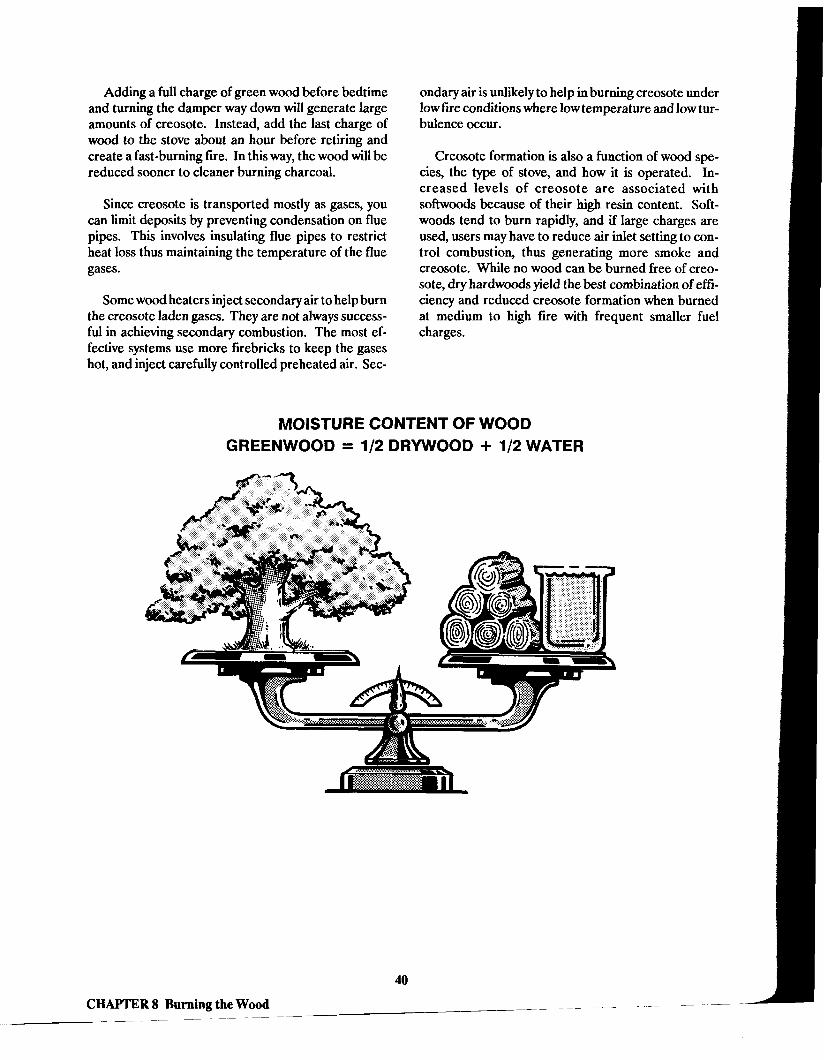
Adding a full charge of green wood before bedtime and turning the damper way down will generate large amounts of creosote. Instead, add the last charge of wood to the stove about an hour before retiring and create a fast-burning fire. In this way, the wood will be reduced sooner to cleaner burning charcoal.
Since creosote is transported mostly as gases, you can limit deposits by preventing condensation on flue pipes. This involves insulating flue pipes to restrict heat loss thus maintaining the temperature of the flue gases.
Some wood heaters inject secondary air to help burn the creosote laden gases. They are not always success- ful in achieving secondary combustion. The most ef- fective systems use more firebricks to keep the gases hot, and inject carefully controlled preheated air. Sec-
ondary air is unlikely to help in burning creosote under low fire conditions where low temperature and low tur- bulence occur.
Creosote formation is also a function of wood spe- cies, the type of stove, and how it is operated. In- creased levels of creosote are associated with softwoods because of their high resin content. Soft- woods tend to bum rapidly, and if large charges are used, users may have to reduce air inlet setting to con- trol combustion, thus generating more smoke and creosote. Whiie no wood can be burned free of creo- sote, dry hardwoods yield the best combination of effi- ciency and reduced creosote formation when burned at medium to high fire with frequent smaller fuel charges.
MOISTURE CONTENT OF WOOD GREENWOOD = 112 DRYWOOD + 112 WATER
CHAPTER 8 Burning the Wood - ---

CHAPTER 9 Emission Standards for Wood Heaters
ood heating can contribute to air pollution prob- w lems where the terrain, climate, weather patterns, and concentration of heaters promote accumulation of pollutants. Colorado and Oregon have experienced problems with air quality due to wood heaters and fue- places and have pioneered testing for emissions. Oregon implemented wood heater regulations on July 1,1986, and Colorado on January 1,1987. Many wood heater models have passed tests for use in these two states.
The U.S. Environmental Protection Agency (EPA) has now set a nationwide standard for emissions from wood heaters. Nationwide, pollution reductions are expected to be 436,000 tons of particulate matter per year by the end of 1991. On February 18,1987, EPA issued New Source Performance Standards for resi- dential wood heaters (published in Code of Federal Regulations Part 60, beginning on page 4994). These standards regulate the levels of particulate matter (not carbon monoxide or polycyclic organic materials). Separate categories are used for catalytic and noncat- alytic models and the standards are implemented in two phases. Phase I guidelines apply to wood heaters manufactured after July 1, 1988 or sold after July 1, 1990. Phase I1 guidelines apply to those manufactured after July 1,1990 or sold after July 1,1992. (See Table 10). Wood furnaces, boilers, open fireplaces, and coal- only equipment are not subject to these regulations.
TABLE 10 EPA Particulate Emission Limits
Phase I Phase I1 Catalytic heaters 5.5 grams/hr 4.1 gramsihr Noncatalytic heaters 8.5 grams/hr 7.5 gramslhr
Typical current wood heaters emit 60 to 70 gramslhour of particulates, hence the 1988 standards will reduce emissions by 72 percent to 82 percent. EPA estimates that redesigning wood heaters will raise non- catalytic heater prices by $120 and catalytic models by $200. They predict that, in the long run, savings in chimney cleaning, chimney fues, and lower firewood consumption (due to higher efficiency) will produce a net savings to consumers.
41
CHAPTER 9 Emission Standards for Wood Heaters

CHAPTER 10 Wood Stove Catalytic Combustors
A catalytic combustor offers two major benefits: (1) more heat from the same amount of wood, and (2)
less smoke pollution, which provides cleaner air, cleaner chimneys (less creosote), and less danger of chimney fires.
Just what is a catalytic combustor? By definition, a catalyst causes a reaction to take place at an altered rate or at a different initial temperature, without be- coming a part of the reaction or its products. In this case, catalytic metals, such as platinum or palladium, are applied to a high temperature ceramic honeycomb or stainless steel mesh. This unit, often called a "cata- lyst" for short, is placed in the heater or stovepipe so that the smoke goes through it before going up the chimney. The catalyst causes the smoke to burn at a much lower temperature than usual.
Common catalyst designs are usually circular, from 5 to 8 inches across, and 1 to 3 inches thick, with 15 to 45 holes per square inch. Currently, ceramic devices are more advanced in design and last longer than metallic ones, but technology for the metallic products is advancing rapidly.
You'll get the best results from a wood heater specifically designed around a catalytic combustor-- about a 10 percent increase in heat output and a 50 per- cent reduction in creosote accumulation. The percentage represents an average over the life of the catalyst and accounts for slow degradation. Tests under optimum conditions for new catalysts showed about twice these savings.
If you already have a wood heater, you can buy ret- rofit catalysts for about $100. Internal retrofits (which fit inside the firebox) will increase heat output by 5 per- cent and reduce creosote accumulation by 35 percent. External retrofits (which fit inside the stovepipe) are slightly less effective.
How tt Works The catalyst is placed close to the fire, inside the
firebox near the top of the heater or just outside the firebox inside the stovepipe. It is important that the catalyst be positioned close to, but NOT in contact with the actual flames. If the catalyst is too far from the fire, it may not become hot enough to play its role in the combustion process, and may actually become clogged with ash and creosote.
All catalysts have a bypass, which is essential during the startup of a fire for two reasons. First, the bypass provides greater air flow that is needed for startup in order to reach the proper operating temperature and to prevent smoke spillage. In addition, it helps prevent clogging of the catalyst, which can occur if too much unburned smoke passes through the catalyst at temperatures below 500'~.
In a catalytic heater, the bypass is commonly a pivot- ing door which automatically opens a path around the catalyst when you open the stove door. Retrofits are equipped with handles that you must move manually each time you add wood.
After the wood has begun burning well, you close the door or move the handles so that the smoke is directed through the catalyst. The smoke contacts the hot catalyst surface and begins to burn. The extra heat is "captured before it goes up the chimney and is trans- mitted to the room, thereby increasing the heater effi- ciency. A surface-mounted thermometer that indirectly measures the catalyst temperature is very useful. It will tell you when the combustor is operating effectively. Some catalytic heaters have two ther- mometers, one positioned before and one after the cat- alyst to verify its operation.
CHAPTER 10 Wood Stove Catalytic Combustors
----

CATALYTIC COMBUSTOR
THIS SIDE TO STOVE
COLLAR BYPASS
IMPORTANT. Heating the catalyst to tempera- tures above 1200~~wil l reduce its useful life. After first reaching 500°, the catalyst should continue to operate satisfactorily if it receives smoke at temperatures ex- ceeding 350%. The catalyst need not be hot enough to glow to continue working.
How To Choose a Retmfrt Placement of the retrofit is important. It must re-
ceive the hot smoke as soon as possible without direct flame contact. The best choice is to mount the catalyst inside the heater where the wood gases are hot enough to burn--at the flue collar. However, in some models the firebox is not high enough or deep enough to keep the catalyst away from damaging flames. You must then use an external retrofit, which commonly replaces a short section of pipe just above the flue collar.
Retrofits require at least 2 to 3 feet of stovepipe fol- lowing the catalyst to ensure that the heat is recovered. The pipe should be 24 gage or thicker (for 6-inch to 10- inch diameter stovepipe) to withstand the extra heat generated by the catalyst.
Retrofits change the draft conditions. If you have problems with smoke spillage, or if you can see the fire through cracks in the heater walls, a retrofit catalyst may not be a good choice.
'iEAT GENERATED BY CATALYST I
CATALYTIC COMBUSTOR
CHAPTER 10 Wood Stove Catalytic Combustors

Getting the Most from a Catalyst To get the best performance from a catalytic heater
or retrofit, proper use and maintenance are important. The catalyst should last for approximately three years if the manufacturer's instructions and the tips below are followed:
Be careful not to burn trash. Some of the chemi- cals in your trash can clog the catalyst. Do not burn painted wood, colored paper (such as wrap- ping paper or the Sunday comics), plastics, rub- ber, treated lumber, or coal. Metallic components and other chemicals in these materials poison the metal in the catalyst and cause it to lose its ability to burn the smoke.
Always bypass the catalyst during startup and loading.
Use as small amount of paper as possible to start your fire. Although burning regular (black and white) paper should not cause fouling, the large ash flakes (which are familiar to anyone who has burned paper) can collect on the entrance of the catalyst and prevent proper smoke flow.
Avoid overlunderheating. Having too much air flow can force much of the heat to go up the flue, without giving the catalyst sufficient time to react with the smoke. An automatic intake air regulator will help maintain a proper operating temperature and better catalyst performance by assuring a good mixture of intake air with the burning wood and smoke. Also helpful is a barometric draft con- trol device (located above the catalyst) which regulates draft in the heater and helps limit the in- tensity of the fire. Another benefit of the barometric draft control is that soot and creosote are more effectively cooled and swept out of the chimney after leaving the catalyst, helping to fur- ther decrease creosote accumulation inside the flue pipe.
Check the catalyst once a month to make sure it isn't clogged.
Even with the greatest care, smoke particles and creosote may slowly collect on the catalyst.
Keep the Catalyst Clean See the manufacturer's instructions for the best way
to clean your catalyst. Building a hot fire burns off the deposits on the catalyst. This is the one exception to the rule against overheating. Be sure your chimney is free of excessive creosote so you don't start a chimney fire. Burning a moderately hot fire each day will help prevent buildup on the catalyst, but occasional inspec- tions to be sure that the catalyst remains fairly clean are still advisable.
If the danger of starting a chimney fire is too great, or if your attempt to clean the catalyst by burning a hot fire fails, you'll need to remove the catalyst from the heater or flue pipe for easier cleaning. If recommended by the manufacturer, you may use a propane torch to burn off the deposits. Lightly brush off any debris in- side or around the catalyst. Avoid hitting the catalyst too hard because the supporting structures are fragile and may crack or break. Also, avoid scrubbing the cat- alyst too roughly--you may remove the catalytic coat- ing.
44
CHAPTER 10 Wood Stove Catalytic Combustors

Economics Although many of the benefits of a catalytic combus-
tor cannot be measured in terms of dollars saved, it is helpful to consider the time needed to pay for the cost of the catalyst with the energy savings gained. This pay- back period is shown in the figure below using typical costs of $100 for a retrofit installation and a $200 pre- mium for a catalytic designed wood heater.
If you are considering the purchase of a retrofit, then the graph shows the time needed to pay for $100 of the original cost. To use the graph, first estimate the num- ber of cords of wood used each year (in Georgia, usu- ally between three and four), locate this number on the horizontal axis, then look up for the line representing the cost of the wood you buy. The number of years to pay back $100 spent on a retrofit is then found by look- ing to the left axis. For example, if you use four cords of wood a year, and it costs $75 per cord, the payback period for $100 of the cost of a retrofit is about 3 V2 years.
When considering the purchase of a catalytic wood heater, the graph can be used in the same way to esti- mate the time needed to pay for $200 of additional cost of the heater. The same graph can be used because the
energy savings is about twice as great, but remember that the payback period is for each $200 portion of the extra cost, not $100 as for the retrofit.
The graph can be used as a guideline for determin- ing the economic value of a catalyst. The important factor is whether or not the savings from the catalyst will pay its cost before the life of the catalyst ends. This life is for the actual honeycomb or mesh inset, and can be assumed to be about 3 years or 15 cords, whichever comes first.
Replacement catalyst elements are available at a cost of about $50 to $70 each, or about one-thud the cost of the original installation. Hence, payback peri- ods for replacement elements are three times faster (e.g., 1 year instead of 3 years).
Although estimates can be made of the economic benefits of a catalyst, it is difficult to describe in dollars the other benefits gained. Because creosote accumu- lations are reduced by such a large amount, the risk of chimney fire is reduced, as is the need for more frequent chimney sweeping. The value of reducing pollution is hard to estimate in dollars, though easy to understand in terms of protecting the environment.
PAYBACK PERIOD FOR CATALYSTS NOTE: This graph shows the payback period for retrofit catalysts costin $100 and ~n-stove catalysts msting $200. yo corm3 for different costs, multiply the payback period by the factor:
ACTUAL COST EXAMPLE COST = $1 00 OR $200
2 . .
CORDS BURNED PER YEAR
45
CHAPTER 10 Wood Stove Catalytic Combustors

Furnaces, Boilers, Multi-fuel Appliances, and Central Systems
C entral heating systems fired with wood improve heat distribution throughout the house and allow
refueling without having to bring wood into the living area. However, they do not radiate heat into the house, have a much higher installed cost, and cannot operate during power outages. In general, central systems are better matched to large homes in colder climates such as New England where the heating requirements are twice those of Georgia.
The most popular central units are forced air fur- naces which burn wood and are controlled by an auto- matic thermostat in the heated area of the home. When heat is called for, the air inlet damper to the heater is opened, the wood fire grows hotter, and the air circulation fan brings heated air to the house. Prices for a central wood furnace are typically in the $1500 to $2500 range without installation. These sys- tems are large and complex and require a knowledge- able professional to ensure a safe and efficient installation.
Smaller wood furnaces are available which work in conjunction with an existing warm air furnace. While these are less costly, they are difficult to install prop- erly and the control strategy can become complicated. Avoid installations where the warm air furnace's circu- lating fan places the firebox of the wood furnace under negative pressure. Smoke and carbon monoxide could enter the house if a leak developed. Some installations use parallel ductwork and backdraft dampers to isolate whichever furnace is inoperative. Follow the manufac- turer's instructions carefully; again, homeowner instal- lation is not advised.
Combination units are available which burn oil or gas as well as wood. They allow startup without build- ing a wood fire, and they provide heat even when the wood charge has been exhausted. In mild fall and spring weather, the fossil fuel can do the job at low cost without the problems associated with overheating or burning wood under smoldering conditions. These
units are several hundred dollars more expensive than wood only furnaces.
Boilers and hydronic heating systems are another wood heating option. However, these have little appli- cation in Georgia since few homes have radiators or hydronic convectors. While hydronic fireplace grates and hydronic heat exchangers for use with wood heaters are made, the output is too small to heat a home, and the high cost and safety problems far out- weigh the benefits from heating domestic hot water.
A recent entry into the wood heater market is a hy- brid of space heater and furnace technology. It is a heater with a built-in power gas burner. A thermostat in the room controls the gas burner. If the wood fire is
COMBINATION WOOD AND GAS HEATER
WOOD
BURNER
sufficient, gas is not used. When the temperature drops (via the fuel being consumed or the fire being in- sufficient to handle the load in cold weather), the gas burner takes over. It can also be used to start the fire, and used without wood in mild weather. One model incorporates soapstone to help store heat. Prices of this combination heater are roughly double that of a comparable wood-only heater.
On a safety note, you should NEVER attempt to use a wood heater as a central furnace. Conversions, such as using a hood over the heater, are likely to violate the listing of the unit as well as safety codes for equipment design. Failure of the integrity of the heater could quickly send smoke and carbon monoxide throughout the house.
46
CHAPTER 11 Furnaces, Boilers, Multi-fuel Appliances, and Central Systems

CHAPTER 12 Fireplaces
F ireplaces provide charm and ambience, not heat. Typical masonry fireplaces are 10 percent efficient,
with less than one-fifth the heat output of a typical airtight wood heater. More efficient fireplace designs do exist. They include masonry types with internal heating passages, factory-built zero-clearance units with hot air ducts, and built-in fireplaces with glass doors (hybrids of a wood stove and a fireplace). These more elaborate units range from 20 percent to 40 per- cent in efficiency. In general, fireplaces cost approxi- mately twice as much as a wood stove of comparable quality. New zero-clearance controlled combustion fireplaces are a hybrid of a fireplace insert, airtight woodstove, and zero-clearance fireplace. They are in- stalled much like a zero-clearance fireplace but have tight-fitting glass doors, a large surface area to heat air for the room, and good control of combustion air.
The manufactured zero-clearance fireplaces are the least expensive types, and most easily installed in ex- isting homes. Traditional brick fireplaces cost 50 per- cent to 100 percent more but are more versatile since they can accept a wood stove insert. Factory-built fire boxes, with or without heat reclaimers are also popu- lar, offering more predictable operation. This type uses a thick steel (usually 114-inch) firebox, installed in a masonry surrounding, and either a factory-built Class A chimney or a standard brick c h i i e y with a tile liner.
Much of the heat which is produced by a fireplace is radiant. A mesh firescreen will still allow most of this heat into the room, but glass doors will not. Glass doors are only useful when: a The fire is out or nearly out, to cut air loss up the
chimney.
a The fireplace is equipped with a fan to transfer heated air into the room.
The design of masonry fireplaces is a fascinating and widely discussed subject. Since they are field-built and no two are exactly alike, the temperaments of two "identical" fireplaces may still vary. The major design variables have been defined over the years, however. For example, the flue size must be in the proper ratio to the opening of the fireplace; and the length, height, and depth of the opening must be in proportion as well.
CONNECT TO USTED - CLASS A CHIMNEY
TYPICAL 2-INCH CLEARANCE TO FRAMING; FOLLOW MANUFACTURER'S RECOMMENDATIONS.
ZEROCLEARANCE FIREPLACE
FIRECLAY FLUE UNER I 112-INCH AIRSPACE
BASE ASSEMBLY
CHAPTER 12 Fireplaces

FIREPLACE DESIGN - TOP VIEW
MASONRY FILL BACK"P WALL BEDDED IN MORTAR
i' MINIMUM 1-INCH FIREBRICK AIRSPACE HEARTH
Selected information from NFPA, the Brick Institute, and the One and Two Family Dwelling Code on fue- place design is provided in Tables 11 and 12.
These dimensions are the major design elements. However, the taper of the opening from front to back, damper size, smoke shelf, taper of the rear wall, and many other variables are all important. For more detail on fireplace construction, refer to the Brick In- stitute Technical Note 19.
Masonry fireplaces must have the back and sides made of a minimum of 8 inches of solid brick or ma- sonry when provided with a firebrick liner. Without a firebrick liner, a minimum of 12 inches of brick or solid masonry is required. In addition to the usual 2-inch clearance to combustibles and firestopping, a clear- ance of at least 4 inches is required from the back face
TABLE 11
Standard Single Face Fireplace Dimensions (in inches)
Height Width Depth Flue Size Lintel 24 24 16 8 x 12 3 x 3 x 3/16 24 28 16 8 x 12 3 x 3 x 3/16 29 30 16 12 x 12 3 x 3 x 3/16 29 36 16 12 x 12 3 x 3 x 3/16 32 42 16 16 x 16 3 V2 x 3 x 1/4 32 48 18 16 x 16 3 1L2 x 3 x 114
of the fireplace. Woodwork (such as mantels) or other combustibles should not be placed within 6 inches of the fireplace opening. Above the fireplace opening, combustible material projecting more than 1 1Dinches must not be placed within 12 inches of the opening.
The dimensions given are for a standard fireplace. Many other types exist, including those open on two and three sides, the "Brickolator" with internal heating passages, and the "Russiann fireplaces or stoves which use massive amounts of masonry to store heat. While these fireplaces are attractive esthetically and may be more efficient, some have a greater tendency to smoke, and most cost substantially more than a standard fue- place. The higher efficiency is rarely a factor in the long run--few people serious about heating with wood ever use a fueplace for that purpose. Fireplaces are best for occasional use and holiday cheer, not for heat- ing a home.
TABLE 12
Masonry Fireplace Dimensions Size of Fireplace Opening Hearth Extension Length Minimum Dimension
(on side past opening)
Opening less than 6 sq ft 16 inches 8 inches
Opening 6 sq ft or larger 20 inches 12 inches
Type of Flue Ratio of Flue Area to Fireplace Opening
Minimum Flue Area
Round flue tile 1/12 of fireplace opening not less than 50 square inches
Square flue tile 1/10 of fireplace opening not less than 64 square inches
Unlined or lined with firebrick 118 of fireplace opening not less than 100 square inches
CHAPTER 12 Fireplaces

CHAPTER 13 Wood Heating for Mobile Homes
M anufactured homes, more commonly known as mobile homes, have special and more restrictive
codes for the installation of woodburning equipment. Mobile home fires due to improper installation have been notably high. This type of housing tends to have smaller room sizes, more use of combustible building materials, and may have lower air infiltration rates. These factors require a different approach to wood heating equipment than for conventional housing. The U.S. Department of Housing and Urban Development (HUD) has developed standards for mobile homes to respond to these problems and enhance safety.
Factory-built fireplaces and wood heaters must be listed for use in mobile homes. The appliance must be
LISTED WOOD HEATER FOR MOBILE HOMES
SPARKARRESTORCAP
MOBILE HOME FLASHIN
3Ff.'MlNlMUM
STORM COUAR
NONCOMBUSTIBLE
24 GAUGE SHEET
LISTED CLASS A CHIMNEY -OR LISTED CONNECTOR
TO CHIMNEY
> FLUE COUAR
HEARTH PAD
METAL AIR INLET DUCT MOBILE HOME CHASSIS
securely fastened to the structure. A listed, factory- built chimney with rain cap and spark arrestor must be installed. The appliance, air intake assembly, hearth extension, and chimney must be installed in accord- ance with the listing and manufacturer's instructions.
Outside combustion air is required for both wood heaters and fireplaces. The air must be ducted directly from the outside of the dwelling to the combustion chamber. The inlet should be screened to prevent an- imal entry, and no ashes or fuel must be able to drop from the fire chamber into the inlet duct or beneath the home.
Do not install the heater or fireplace in a sleeping room. Maintain clearances to combustible walls and ceilings according to the manufacturer's instructions.
Approved, noncombustible floor protection must be installed, at least 318-inch thick, extending at least 16 inches in front of the stove or fireplace and 8 inches on the remaining sides. On elevated fireplaces and for stoves, this floor protection must cover the entire area beneath the appliance.
Venting can be accomplished via an integral vent system listed as part of the appliance, or a venting sys- tem consisting entirely of listed components installed in accordance with the terms of the appliance listing and manufacturer's instructions.
Single-wall stovepipe is not allowed as a connector from the heater to the chimney. The chimney must connect directly to the heater or have double- or triple- wall pipe made specifically for connecting the appli- ance in mobile home service. If the chimney vents out the wall, it must be enclosed or protected to above 7 feet from ground level.
Chimney height follows the standard rules for wood heater installation. The chimney must extend a min- imum of 3 feet above where it penetrates the roof, and at least 2 feet above any portion of the roof within 10 feet. Portions of the chimney more than 13 V2 feet above grade may be removed for road shipment.
CHAPTER 13 Wood Heating for Mobile Homes
I - .- -

Ouestions and Answers about Wood Heaters
Q. How much wood does a heater use during a cold 24-hour period? A. An airtight heater will use from 14 to 16 hardwood logs that are 24 inches long. A nonairtight heater will need considerably more. If you are burning pine or other softwoods, more logs will be consumed.
Q. Will I have to stoke the fire during the night? A. Most people find this unnecessary as banking the fire and closing the damper will usually keep the house warm through the night.
Q. How offen do I need to check on the heater? A. Every time wood is put in is an appropriate time to do a quick check. When the owner is home during the day, wood is usually added two or three times. Wood heaters are rarely used when the owners are gone.
Q. How accurately can the temperature of a stove be controlled? A. An airtight heater can usually be regulated to maintain room temperature within five degrees. The temperature of a nonairtight heater can fluctuate widely, and it is a good idea to have a damper in- stalled in the stovepipe. Some heaters come equipped with an automatic thermostat; these are also ac- curate within five degrees.
Q. Where do I get wood? A. A little imagination and a little effort can provide you with all the wood necessary to heat your home. Cutting wood from your own property or a friend's property is the most convenient. You can also pick up scrap lumber from new subdivisions or where houses are being torn down. Some people search on the side of the road and follow phone and power company trucks when they cut down trees.
Q. How much does wood cost per cord? A. Price depends on how much of the work you want done for you. To have it delivered, cut, split, and stacked in your yard is more expensive than if you pick it up and split it yourself. On the average, wood costs $60 to $100 a cord.
Q. What is the best way to store wood? A. Stack it, crisscross fashion off the bare ground with a cover on top to keep it dry and still allow for ventilation. Season it for at least six months after cutting.
Q. Do most people use wood as a secondary heat source? A. Most wood heater owners keep their gas or electric furnaces in operating order in case of illness or extreme cold weather, even though wood provides a large percentage of their space heat. Homes with no conventional backup systems are generally in rural areas where wood is plentiful.
Q. What complaints are heard most often about wood heaters? A. They take getting used to; an adjustment period is necessary. Initial problems with lighting the heater and excess smoking are most common, and temperatures fluctuate a good bit until the owners get to know their own heaters.
50
Questions and Answers about Wood Heaters

Q. How often should I check my chimney or stovepipe for creosote buildup? How often do I have to clean it? A. On a new installation, check it every three to four weeks to determine buildup rate. Clean once a season or when a quarter-inch of creosote accumulates. If you're using considerable amounts of pine or green wood, the creosote may build up faster.
Q. How big an area do people try to heat with a wood heater? A. Anywhere from 800 to 2200 square feet. How warm you stay will depend on the amount of insula- tion in the house and the air flow through the house.
Q. Where do most people place their wood heaters? A. In the living room or den -- usually the largest room or gathering place for the family.
Q. How much is really saved on heating bills? A. For those people who have converted to wood heat and use it regularly, the savings are 50 percent or better.
Q. Why do people buy wood heaters? A. Most buy because they save on heating bills. Some buy them because their families have always had one. Many buy them to add charm to a room.
Q. Does a wood heater contribute extra dirt or ashes in the home? A. The only excess dirt is from carrying in wood, but for many people a wood box has solved that prob- lem. Remember to check each log for wood roaches or ants before you bring it in the house. Fine ash accumulation in the home can be a sign of bad draft or leaks in the heater system.
Q. How often is ash disposal necessary? A. Anywhere from twice a week to once a month, depending on the type of heater you have and the rate of use. Remember to keep a thin layer of ashes on the bottom of the firebox to protect the metal from high temperatures.
Q. What precautions can be taken to prevent fires? A. Have your chimney inspected by the fire department. A fire extinguisher and smoke detector are recommended. Follow directions from the wood heater manufacturer on clearances for installation, and instruct all family members on safe operation of the heater.
Q. Are there codes or regulations that restrict placement of the heater? A. There are many regulations to follow. Manufacturer's instructions or NFPA publication No. 211 are good sources on heater installation. Many counties restrict installation to those units approved by a recognized testing agency such as Underwriters' Laboratory.
Q. Do owners of wood heaters enjoy their benefits? A. Yes! The charm of having wood heat in the home, a warmer winter environment, and fuel savings are all benefits cited by wood heater owners.

Reference List for Woodburners
Firewood and Forests HOW TO SELECT, CUT, AND SEASON GOOD FIREWOOD
John Vivian Customer Service Dept., Stihl, Inc. 536 Viking Drive Virginia Beach, VA 23452 (804) 486-8444
THE MAINE WOODBURNING GUIDE Office of Energy Resources State House Station 53 Augusta, ME 04333 (207) 289-3811
WHAT YOU SHOULD KNOW ABOUT FIRE- WOOD--BEFORE YOU BUY
Tennessee Valley Authority Director of Information 400 West Summit Hill Drive Knoxville, TN 37902 (800) 251-9242
NFPA Safety Publications National Fire Protection Association Batterymarch Park Quincy, MA 02269 (800) 344-3555
CHIMNEYS, FIREPLACES, VENTS, AND SOLID FUEL BURNING APPLIANCES, No. 211
HOMES, FOREST AREAS, No. 224
HOUSEHOLD WARNING EQUIPMENT, No. 74
STORAGE OF FOREST PRODUCTS, No. 46
Heaters and Chimneys SOLID FUELS ENCYCLOPEDIA, WOODBURNERS ENCYCLOPEDIA, and WOOD HEAT SAFETY
Jay Shelton Shelton Research Inc. PO Box 5235 Santa Fe, New Mexico 87502 (505) 983-9457
MODERN AND CLASSIC WOODBURNING STOVES
Bob and Carol Ross The Overlook Press Route #1, Box 4% Woodstock, NY 12498 (914) 679-6838
CHIMNEY AND STOVE CLEANING Storey Communications/Garden Way Publishing Schoolhouse Rd. Pownal, W 05261 (802) 823-5811
SAFE AND SOUND MASONRY CHIMNEYS Tennessee Valley Authority Director of Information 400 West Summit Hill Drive Knoxville, TN 37902 (800) 251-9241
FIREPLACES AND WOODSTOVES Time-Life Books 541 North Fairbanks Court Chicago, IL 60611
PORTABLE EXTINGUISHERS, No. 10
Reference List for Woodburners

THE WOODBURNERS HANDBOOK D. Havens Harpswell Press, 132 Water St., Gardiner, ME 04345 (207)582-1899
OER Energy Conservation Publications The Governor's Office of Energy Resources 270 W a s h i i o n St., NW Suite 615 Atlanta, GA 30334 (404) 656-5176
HOME ENERGY PROJECTS: An Energy Conser- vation Guide for Do-It-Yourselfers
Southface Energy Institute
HOMEOWNER'S GUIDE TO ENERGY EFH- CIENT AND PASSIVE SOLAR HOMES
Southface Energy Institute
A BUILDER'S GUIDE TO ENERGY EFFICIENT HOMES
Southern Building Code Congress, International Inc. and the National Conference of States on Building Codes and Standards, Inc.
ABUYER'S GUIDETO ANENERGY EFFICIENT HOME
Mobius Corporation
Directories and Organizations BRICK INSTITUTE OF AMERICA
Region 9 8601 Dunwoody Place Dunwoody, GA 30350
WOOD HEATING ALLIANCE 1101 Connecticut Ave. NW, Suite 700 Washington, D.C. 20036
Reference List for Woodburners
- -

Wood Heating Checklist
Wood Heater Design o Airtight model with good efficiency rating.
Tested by UL or other reputable agency.
o Catalytic combustor to increase efficiency and safety.
Properly sized for area of home to be heated.
Easy-to-understand manual that covers installation requirements, operating procedures, maintenance needs, and warranties.
Location in the Home Adequate air circulation to distribute heat.
Easy traffic flow around heater.
Adequate access for loading wood and removing ashes.
Away from central heating system thermostat.
Installation (Note: For listed heaters, follow the manufacturer's guidelines. For unlisted heaters, use the manufac- turer's guidelines or the following recommendations, whichever are greater.)
o Minimum 36-inch clearance between heater and all unprotected combustible materials.
a Proper clearance reduction materials to protect combustibles, if clearances are less than 36 inches.
o Heater placed on a noncombustible floor or ap- proved floor protection material.
M i n i floor protection of 18 inches from the front, sides, and rear of the heater.
Minimum 18-inch clearance between stovepipe and all combustibles, or combustible material is pro- tected by clearance reduction system.
o Approved thimble or chimney section used to vent through walls.
Chimney height at least 3 feet above the roof and at least 2 feet higher than anything within 10 feet.
Operation Fires started with minimum paper and kindling. Only seasoned wood should be burned--never trash or artificial logs.
Wood added frequently in small amounts.
Air inlets opened for 60 seconds before adding wood to a fire.
Coals and ashes completely extinguished before dis- posal.
Safety Chimney and heater inspected and cleaned on a reg- ular basis.
Smoke detectors located between heater and bed- rooms.
Fire extinguisher, gloves, and bucket of sand near wood heater.
All family members and guests know two fire escape routes from each room.
Fire emergency telephone numbers beside all phones.
First aid kit easily accessible.
Wood Heating Checklist