wood turning
TRANSCRIPT

INTRODUCTION
Fig. 7
work is of such character that it cannot be held between
centres. It is attached to the live-spindle by the screw on
the end, and is used in
turning cups, balls, disks,
and such other pieces as
require that turning-
tools be used on one
end. The piece being
operated on is not fast-
ened directly to ft\t face-
plate, but is held in a wooden disk that is fastened to the
face-plate by means of screws. This disk is called a chuck.
Face-plates are made in va-
rious diameters to suit the
size of the work. When
they are made more com-
plex in character, as with
raised rims and attachments
in the form of adjusting-
screws, they are themselves
called chucks.
The swing of a lathe is twice the distance from the
centre of the front end of the live-spindle to the nearest
point of the shears.
The size of a lathe
is determined by the
swing and the length
of the shears.
The Gouge,shown in Fig. 9, is the
tool of greatest use to
the wood -turner. Any piece to be turned is first rapidly
dressed to a rough approximation to the desired form by
Fig.
Fig. 9

8 WOOD-TURNING
Fig. 10
means of the gouge ;and most surfaces having compound
curves are shaped by its use. In the hands of a skilful
wood-turner it may be made to do most of the work done
in the lathe. The edge should be a smooth curve of the
elliptical form shown, and the bevel should be straight, as
it is the guide by which the depth and outline of curves
are regulated. The
elliptical form is nec-
essary in order that
it may be turned in a
small space. The han-
dle ought to be longin large sizes, in order
to give command of the tool during a heavy cut. The size
is determined by the width across the concave side, and
varies from a quarter of an inch to three inches by eighthsof an inch.
The Skew Chisel, shown in Fig. 10, is used in finish-
ing straight outlined work, such as the cylinder and cone,
and for making convex curves and beads. It is bevelled
from both sides to the cutting edge, which, instead of beingat a right angle to the
side of the tool, as in the
carpenter's chisel, is
" skewed"slightly. This
gives better command of
the cutting edge, because
of a better position of the handle. The edge ought to be
straight and the bevel flat, as by these is regulated the
depth of the cut. The size is determined by the width of
the blade. The larger sizes ought to have proportionally
long handles.
The smaller sizes of chisels having straight edges are
Fig. ii
INTRODUCTION
Fig. 12
sometimes ground in such manner that the edges are at
right angles with the sides, to avoid the necessity for re-
versing them when in use.
The Round-noseChisel, shown in Fig. 1 1,
is usually made by grind-
ing the edge of a carpen-
ter's chisel to the elliptical
form of the gouge. This tool is used in cutting recesses
where the use of the gouge would be dangerous. Skilful
turners frequently use the gouge for nearly all the work
for which this tool is commonly used.
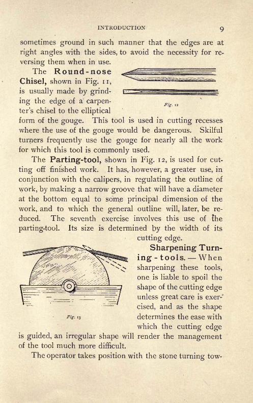
The Parting-tool, shown in Fig. 12, is used for cut-
ting off finished work. It has, however, a greater use, in
conjunction with the calipers, in regulating the outline of
work, by making a narrow groove that will have a diameter
at the bottom equal to som.e principal dimension of the
work, and to which the general outline will, later, be re-
duced. The seventh exercise involves this use of the
parting-tool. Its size is determined by the width of its
cutting edge.
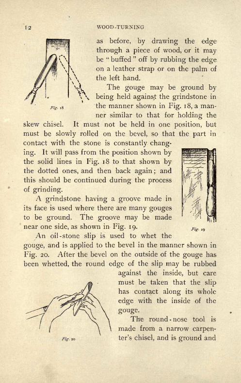
Sharpening Turn-
ing -tools. Whensharpening these tools,
one is liable to spoil the
shape of the cutting edgeunless great care is exer-*
cised, and as the shapefig- 13 determines the ease with
which the cutting edgeis guided, an irregular shape will render the managementof the tool much more difficult.
The operator takes position with the stone turning tow-

10 WOOD -TURNING
Fig. 14
ards him, and applies the tool in the position shown by the
dotted lines in Fig. 1 3, and at once carefully draws it back
to the position shown by the solid ones, with
the bevel resting on the stone. The chisel
is applied in this manner to avoid the dangerof touching the cutting edge against the re-
volving stone, and so making it duller than
before. The bevel is held square across the
face of the stone, as shown in Fig. 14, where
the solid lines show the position when one
side is being ground, and the dotted lines when the other
one. The^tool should be moved slowly across the face of
the stone, so that the whole of the face may be used, and
it must not be allowed to rock, as that would round the
bevel. The position
of the operator is
shown in Fig. 15.
The grinding is
complete when the
ground surface
reaches the cutting
edge, and this can
readily be seen by
holding it so that
the light from a win-
dow falls across it.
*If the grinding be
continued after this,
the extreme end, be-
coming thin from
the grinding, bends
away from the stone,
producing what is Fis. I5

INTRODUCTION I I
called a " wire edge." The wire edge will have to be bro-
ken off before the tool can be properly sharpened, and this
is usually done just before it is applied to the whetstone.
It may be done by drawing the cutting edge in the direc-
tion of its length across the grain of a piece of soft wood.
Fig. 16
The edge left by the grindstone is too rough for use in
turning, so to secure the necessary smoothness and to fur-
ther sharpen the tool the whetstone is used. The chisel is
applied to the whetstone with the same care with which it
was applied to the grindstone. It is first placed in the
position shown by the dotted lines in Fig. 16, then raised
to that shown by the solid
lines, and is then moved
steadily back and forth on
the stone; this operation
being performed on both
bevels until it is sharp. Themanner of grasping the
chisel during the operation Fig. 17
of whetting is shown in
Fig. 17. The chisel is held in the right hand, and the
fingers of the left hand used to steady it. When the
sharpening is nearly complete, the tool is frequently turned
over from one bevel to the other and given a few rubs on
each. Any fine wire edge now formed may be removed,
12 WOOD-TURNING
Fig. 1 8
as before, by drawing the edge
through a piece of wood, or it maybe " buffed
"off by rubbing the edge
on a leather strap or on the palm of
the left hand.
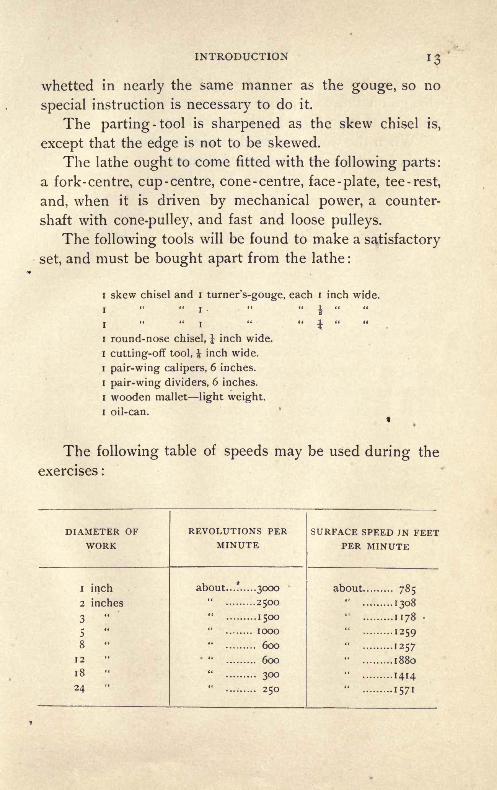
The gouge may be ground by
being held against the grindstone in
the manner shown in Fig. 18, a man-
ner similar to that for holding the
skew chisel. It must not be held in one position, but
must be slowly rolled on the bevel, so that the part in
contact with the stone is constantly chang-
ing. It will pass from the position shown bythe solid lines in Fig. 18 to that shown bythe dotted ones, and then back again ;
and
this should be continued during the process
of grinding.
A grindstone having a groove made in
its face is used where there are many gougesto be ground. The groove may be made
near one side, as shown in Fig. 19.
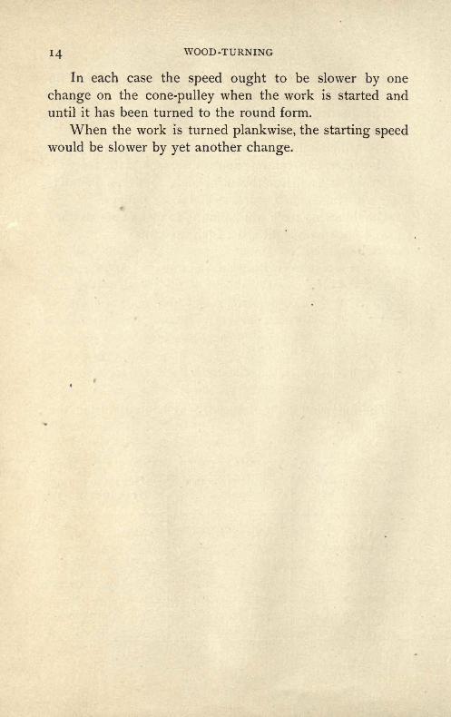
An oil-stone slip is used to whet the
gouge, and is applied to the bevel in the manner shown in
Fig. 20. After the bevel on the outside of the gouge has
been whetted, the round edge of the slip may be rubbed
against the inside, but care
must be taken that the slip
has contact along its whole
edge with the inside of the
gouge.The round -nose tool is
/\ \ made from a narrow carpen-
ter's chisel, and is ground and
Fig. 19
INTRODUCTION
whetted in nearly the same manner as the gouge, so no
special instruction is necessary to do it.
The parting -tool is sharpened as the skew chisel is,
except that the edge is not to be skewed.
The lathe ought to come fitted with the following parts:
a fork-centre, cup-centre, cone-centre, face-plate, tee-rest,
and, when it is driven by mechanical power, a counter-
shaft with cone-pulley, and fast and loose pulleys.
The following tools will be found to make a satisfactory
set, and must be bought apart from the lathe :
i skew chisel and i turner's-gouge, each i inch wide.
i i
i" "i
round-nose chisel, i inch wide.
cutting-off tool, i inch wide.
pair-wing calipers, 6 inches.
pair-wing dividers, 6 inches.
wooden mallet light weight.
oil-can.
The following table of speeds may be used during the
exercises :
14 WOOD-TURNING
In each case the speed ought to be slower by one
change on the cone-pulley when the work is started and
until it has been turned to the round form.
When the work is turned plankwise, the starting speedwould be slower by yet another change.

FIRST EXERCISE
Fig. 21
Material. Poplar or pine, 3" x 3" x 8".
Exercise. To turn a smooth cylinder and mark spaces
across it i inch apart.
Use the fork-centre in the head-stock
and the cup-centre in the tail-stock.
Find the centre of both ends of the
wood, either by drawing diagonals, as
shown in Fig. 21, or by "setting the di-
viders to as nearly one-half of the least
diameter as they can be taken without measuring, and then,
resting the faces of the stock in succession on some flat
surface, drawinglines across the ends
in the way shown in
Fig. 22. These lines
willshowasinFig.23,and the centre of this
smaller figuremaybe
easily guessed, and
will be nearly the centre of the end of the block. Now placethe centre, so found, against the point of the fork-centre and
drive the stock against the fork with a few
light blows of the mallet until the fork pen-
etrates the wood for a short distance, and
then advance the cup-centre against the
Fig 23other end, and force it in also for a short
Fig, 22

i6 WOOD -TURNING
Fig. 24
distance. Put a few drops of oil on the wood where it
has contact with the cup-centre. If the dead-centre be
forced too strongly against the wood, it will pinch the live-
centre against its bearings and stop it from turning or
cause it to heat. The pressure
can be tested by revolving the
live-spindle by hand.
Start the lathe, and. adjust the
belt to the position that will give
the proper speed of revolution
usually the speed next to the slow-
est. When it is desired to changethe position of the belt on the cone-pulley, it must first be" shifted
"to the smaller and then to the larger of the steps
on which it is* to run;
ex-
amination will show that
otherwise the belt would be
stretched.
The wood is first to be
turned to a rough cylinder
with the i -inch gouge. Todo this, adjust the rest to
the position relative to the
wood shown in Fig 24, so
that the cutting tool mayhave its handle slightly low-
er than its edge, and the
edge above the centre of
the work. This makes the
action of the gouge a cut-
ting one, whereas, if the
edge were lower, the action
would be scraping.

FIRST EXERCISE
Fig. 26
The general position of the operator when using the
gouge is shown in Fig. 25. The right hand grasps the
handle near the end and is steadied in its movement by
resting against the side, as shown. The left hand presses
the gouge firmly on the rest and moves the cutting edge
along the work, regulating the depth of the cut by keepingcontact with the-rest.
It will be found that
if the side of the
hand lose contact
with the rest, the
depth of the cut can-
not be regulated so
nicely.
The position of the hands is further shown in Fig. 26
a view of the hands from above.
Advance the cutting edge cautiously, and start a light
cut near one end of the wood, and carry the cut out to the
end near which it was started. The end of the rest oughtto be outside the end of the wood, as shown in Fig. 27.
Start a second cut a short distance inside the first and
continue it tp the end also;and repeat this until the end
is round and 2f inches in diameter. The end will appearas in Fig. 27. The diameter is measured between the
points of the calipers, used as shown in Fig. 28. If the
points of the cal-
ipers are not held
square across the
work, the meas-
urement cannot
be correctly ta-
ken.
Itwill be found27

i8 WOOD -TURNING
Fig. 28
better to stop the lathe
when using the calipers
during the few first
exercises, though, later,
they may be used while
the work is revolving.
Change the position
of the rest to the other
end of the wood, and turn that down in the same manner
as the first, after which place the rest at the centre, and
turn the centre to the same diameter as the ends, using
the ends as guides in determining the size. There will
be no need of the calipers.
Finishing with the Skew Chisel. In using the
skew chisel, the rest is set higher than when using the
gouge the height is determined by the stature of the
operator, the rest being so set that it can be most conven-
iently used.
The manner of grasping the chisel is nearly the same
as with the gouge; it is applied to the work, however, in an
entirely different manner.
In using the skew chisel for straight outline work
three conditions relative to the position of the chisel
must be borne in mind: first, the chisel must have con-
tact of its bevel with the
surface being cut, as in
Fig. 29; second, the
acute angle of the edgemust be kept clear of
the ^ork, and the cut-
ting done between the
corners, as in Fig. 29
and Fig. 30 ; and, third, Fis. 29

FIRST EXERCISE
the chisel must
have contact with
the rest, as in Fig.
29 and Fig. 31.
That the bevel
of the chisel maybe brought into
position without
danger of the edge
catching in the re-
volving wood, first lay it on the work in the position shown
in Fig. 32 and Fig. 33, and then draw it back, swingingthe handle to the
right, until it ar-
rives at the posi-
tion shown in
Fig. 29 and Fig.
In these sketches the left
Fig. 30
Fig- 32 End
Fig. 31
30.
hand is not shown, that the
position of the tool may be
shown more clearly; the hand,
however, grasps the tool as in
Fig. 34, the right hand hold-
ing the end of the handle, as when using the gouge.The bevel of the
chisel should now rest
on the revolving workin the direction shownfrom [x] to [y] in Fig.
35. Raise the handle
slightly until the edgecuts into the surface
'side about TJ of an inch. By

20 WOOD -TURNING
advancing the chisel for a short distance a smooth surface
is produced where the chisel cuts, and this smooth surface
may be used as a guide in
regulating the depth of the
cut as the cutting edge is
advanced to the end of the
wood. Start the cut *
about 2 inches from
the tail-stock end and
produce it to the oth-
er end.
Now turn the chis-
el over and bring the
other bevel into con-
tact with the surface, as the first one was, except that the
Fig- 34 Fig. 35
Fig. 36
handle must be swung to the left, and finish the cut to the
tail -stock end of the- ^^^^^^^^^^^^^^^^wood. The position of
j , |
the hands when cuttingto the tail-stock end is
shown in Fig. 36.
Repeat these cuts un-
*H
i
*/** /"#
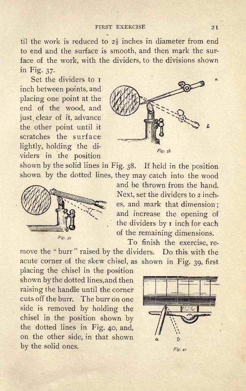
FIRST EXERCISE 21
Fig. 38
til the work is reduced to 2% inches in diameter from end
to end and the surface is smooth, and then mark the sur-
face of the work, with the dividers, to the divisions shown
in Fig. 37.
Set the dividers to i
inch between points, and
placing one point at the
end of the wood, and
just, clear of it, advance
the other point until it
scratches the surface
lightly, holding the di-
viders in the position
shown by the solid lines in Fig. 38. If held in the positionshown by the dotted lines, they may catch into the wood
and be thrown from the hand.
Next, set the dividers to 2 inch-
es, and mark that dimension;
and increase the opening of
the dividers by i inch for each
of the remaining dimensions.
To finish the exercise, re-
move the " burr"raised by the dividers. Do this with the
acute corner of the skew chisel, as shown in Fig. 39, first
placing the chisel in the position
shown by the dotted lines, and then
raising the handle until the corner
cuts off the burr. The burr on one
side is removed by holding the
chisel in the position shown bythe dotted lines in Fig. 40, and,
on the other side, in that shown
by the solid ones.Fig 4o
Fig- 39

SECOND EXERCISE
/ w
Fig-
Material. Poplar or pine, 3"x 3"x 8".
Exercise. To turn a piece of the form and dimen-
sions shown in Fig. 41.
Turn a smooth cylinder 2^ inches in diameter in the
same manner that the cyl-
inder was turned in the first
exercise. Make divisional
marks around it with the
dividers, using the dimen-
sions given in Fig. 41 for
the spaces. Recesses are
to be cut in the alternate
spaces between the marks. Start a recess by holding the
skew chisel in the position shown
in Fig. 39, the acute corner down
and a little inside the mark, and
with the bevel on the side on
which the cut is started, having
the direction in which the cut will
be made, as shown in Fig. 42 'and
Fig. 39. Now raise the handle
and force the corner of the chisel
a short distance into the wood, and
repeat this on the other side of
the space to be cut. Remove the

SECOND EXERCISE
material between these two cuts in the same way as Jthat in
which the surface was made smooth,
except that now the obtuse corner
of the chisel is used in the cutting,
instead of the edge between the
corners.
Use the acute corner of the
chisel in cutting the sides, and take
care that the obtuse corner is clear
of the wood by making the edgetake the position relative to the
side shown in Fig. 42 and Fig. 43at [a].
Keep the corner of the chisel
not in use clear of the work when
removing the material between the
sides.Fig- 43
Finish the central recess first and then the others.
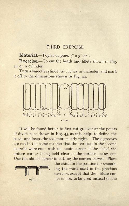
THIRD EXERCISE
Material. Poplar or pine, 3" x 3" x 8".
Exercise. To cut the beads and fillets shown in Fig.
44, on a cylinder.
Turn a smooth cylinder 2% inches in diameter, and markit off to the dimensions shown in Fig. 44.
44
It will be found better to first cut grooves at the points
of division, as shown in Fig. 45, as this helps to define the
beads and keeps the size more nearly right. These groovesare cut in the same manner that the recesses in the second
exercise were cut with the acute corner of the chisel, the
obtuse corner being held clear of the surface being cut.
Use the obtuse corner in cutting the convex curves. Place
___ ^^ the chisel in the position for smooth-
^ ing the work used in the previous
exercise, except that the obtuse cor-
ner is now to be used instead of theIT
45

THIRD EXERCISE
edge between the corners. Cut the curve by passing the
chisel from the position for cutting across, shown in Fig.
46, to that 'for cutting in, shown in Fig. 49, passing it
Fig. 46
through the positions shown in Fig. 47 and Fig. 48. Themovement must be smooth and continuous, and must
not be hurried, the tendency being to hurry the latter
part of it.
Fig- 47
Take care that the handle is swung around and at the
same time raised slightly, as shown in the figures. This
Fig. 48
keeps all of the edge but the cutting corner free of the
work, and keeps it from cutting into and tearing the sur-
face. The chisel passes from the position shown in plan
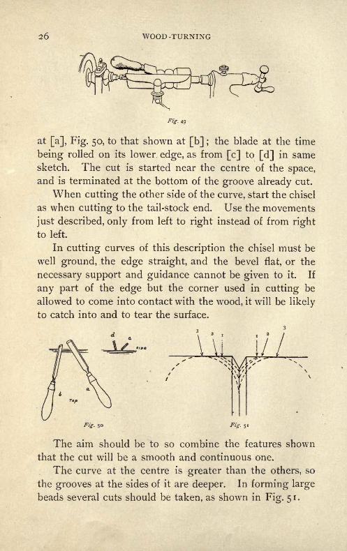
WOOD -TURNING
Fig- 49
at [a], Fig. 50, to that shown at [b] ;the blade at the time
being rolled on its lower edge, as from [c] to [d] in same
sketch. The cut is started near the centre of the space,
and is terminated at the bottom of the groove already cut.
When cutting the other side of the curve, start the chisel
as when cutting to the tail-stock end. Use the movements
just described, only from left to right instead of from right
to left.
In cutting curves of this description the chisel must be
well ground, the edge straight, and the bevel flat, or the
necessary support and guidance cannot be given to it. If
any part of the edge but the corner used in cutting be
allowed to come into contact with the wood, it will be likely
to catch into and to tear the surface.
Ui i/
Fig- 50 Fig- 5i
The aim should be to so combine the features shown
that the cut will be a smooth and continuous one.
The curve at the centre is greater than the others, so
the grooves at the sides of it are deeper. In forming large
beads several cuts should be taken, as shown in Fig. 51.

FOURTH EXERCISE
Material. Poplar or pine, 3^" x 3J" x 8".
Exercise. To cut compound curves of the form shown
in Fig. 52.
-. 52
Turn the wood to a smooth cylinder 3 inches in diame-
ter, and mark it to the dimensions shown in Fig. 53. Both
concave and convex curves are to be half -circles in out-
line. The concave curves
are to be cut first, in the
divisions marked [a],
with the i-inch gouge.The material between
the lines is removed bya series of cuts, as shownin Fig. 54. The exact ^>S3
2?
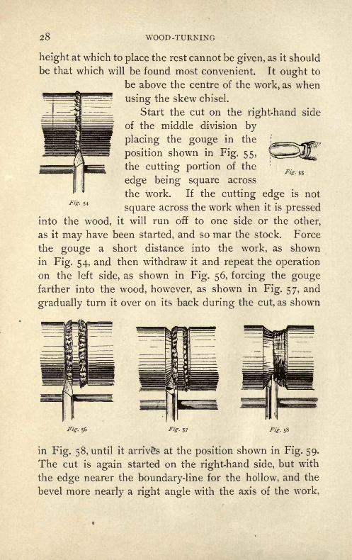
28 WOOD -TURNING
fig- 55
height at which to place the rest cannot be given, as it should
be that which will be found most convenient. It ought to
be above the centre of the work, as when
using the skew chisel.
Start the cut on the right-hand side
of the middle division by
placing the gouge in the
position shown in Fig. 55,
the cutting portion of the
edge being square across
the work. If the cutting edge is not
square across the work when it is pressed
into the wood, it will run off to one side or the other,
as it may have been started, and so mar the stock. Force
the gouge a short distance into the work, as shown
in Fig. 54, aad then withdraw it and repeat the operation
on the left side, as shown in Fig. 56, forcing the gougefarther into the wood, however, as shown in Fig. 57, and
gradually turn it over on its back during the cut, as shown
Fig- 54
Fig. 56 Fig- 58
in Fig. 58, until it arrives at the position shown in Fig. 59.
The cut is again started on the right-hand side, but with
the edge nearer the boundary-line for the hollow, and the
bevel more nearly a right angle with the axis of the work,

FOURTH EXERCISE 29
as shown in Fig. 60. Finish this cut from the left side
as the first one was, and so continue the cutting until the
gouge has taken the position shown in Fig. 61, and the cut
is of the right depth and shape. The sides are straight
for half the depth.
Fig. 59 Fig. 60Fig. 61
Next cut the convex portion of the curve by placingthe gouge in the position shown in Fig. 62, and using it
in nearly the same manner
that the skew chisel was
in the last exercise. The
handle is swung around
in a nearly similar man-
ner, but must be elevated
to a greater extent than
the chisel handle was. Thewhole movement is so near-
ly similar to that of the skew chisel that more detailed de-
scription is not necessary.
The small concave curves near the ends are cut in the
same manner that the larger ones are, the i-inch gougebeing used.
Fig. 62

FIFTH EXERCISE
Material. Poplar or pine, 3" x 3" x 8".
Exercise. To cut the material to the form and dimen-
sions shown in Fig. 63.
s
"M
Jj
Fig. 63
First turn the material to the form and dimensions
shown in Fig. 64, using the skew chisel. Next cut the part

FIFTH EXERCISE
marked [a] with the J-inch gouge. Start the cut on the
right-hand side, holding the gouge in the position shown
in Fig. 65, and keep the cutting part of the edge sup-
ported on the bevel directly behind it. As the cut pro-
ceeds, roll the gouge on its back in such manner that the
cutting portion of the edge changes from the right-hand
side to the left-hand side, where the cut finishes, as shown
in Fig. 65, Fig. 66, and Fig. 67. During this cut each por-
tion of the cutting edge is successively brought into use^as
shown. Take care to have the portion of the edge that is
Fig. 65 Fig. 66 Fig. 67
being used supported, by having the part of the bevel di-
rectly behind it in contact with the revolving stock, and
the corresponding part of the back of the chisel in con-
tact with the tee rest, as shown in the sketches. The
gouge must be grasped quite firmly, and the handle raised
slightly during the cut. The cut is started against the
shoulder on the right-hand side and finished against the
one on the left-hand side of the curve to be cut.
The curve marked [b] is cut in a similar manner, the di-
rection of the cut, however, being from left to right instead

3 2 WOOD -TURNING
of from right to left, as here the cut starts against the
shoulder on the left-hand side and finishes against the oneon the right-hand side.
Cut the curve marked [c] by starting the cutting edgeagainst the shoulder on the right-hand side in the samemanner that it was started when cutting [a], and roll the
gouge on its support from right to left,
as before, carrying it slightly farther in
the movement, and drawing it a verylittle way backward towards the end
of the cut. The cut starts against the
shoulder on the right-hand side, in
the position shown in Fig. 65, and fin-
ishes against the cylinder on the left-
hand side, in the position shown in Fig.
68. In this cut the handle of the gougeis swung around to a slightly greater
extent than when cutting the curve [a].
The part marked [d] is cut in a similar manner to [c], the
movements, however, being from left to right instead of
from right to left.

SIXTH EXERCISE
Material. Hickory or ash, 2/
'x 2// x8 //
.
Exercise. To make a chisel-handle of the form and
dimensions shown in Fig. 69.
It is sometimes
necessary to turn a
number of pieces to
be precisely alike of
such things as han-
dles,'
balusters, and
similar articles. To avoid the necessity for frequent ad-
justment of the measuring tools a "templet" of the form
shown in Fig. 70 is made. The templet may consist of a
Fig. 70

34 WOOD -TURNING
piece of sheet-iron, or of wood and iron, as shown in the
sketch, or be entirely of wood. The principal dimensions
for length are notched on one edge, and the caliper sizes
to correspond are cut out of the other, as shown in Fig.
70.
To Make the Handle. First turn the stock to the
diameter represented by the largest opening in the templet,and then hold the notched edge of the templet against it,
and mark lines around it to correspond to the notches on
the edge of the templet, as shown in Fig. 71. Next, with
the parting -tool,
cut grooves into
the wood where
the marks were
made, using the
notches cut from
the edge of the
templet, instead ofFig. 71
.
the calipers, to de-
termine the diameter of the work, as shown in Fig. 70,
using the opening that corresponds to the notch whose
mark is being cut. After the grooves have been cut, the
work will have the form shown in Fig. 72. Next, using
the skew chisel and gouge, finish the work tp the desired
form, referring frequently to the pattern, to be sure the
wood is assuming the correct outline.
After the wood has been cut to the desired form, it mayhave a coat of oil given to it, and then be polished by rubbing
Fig. 72
SIXTH EXERCISE 35
it with a rag while it is revolving, or a coat of varnish maybe given to it.
Good results may be gotten in this and the succeedingexercises by using a shellac varnish made by dissolving
amber shellac in alcohol and applying a thin coat with a
brush. The wood ought then to be put away for an hour
to dry and harden, when it will be found that the varnish
has caused small particles of the wood to project from the
surface. These may be removed with a piece of fine sand-
paper, care being taken that the sandpaper is applied with
only enough pressure to remove the hard particles and not
to scratch the surface. The surface is then wiped clean of
dust and another coat of the varnish applied, and this is
continued until the desired effect is obtained.
When the varnishing and polishing are complete, trim
off the ends by which the piece was held in the lathe;
Balusters and other similar pieces may be turned in
this way, a way used when there are many pieces to be
turned that are to be alike.

SEVENTH EXERCISE
Material. Gum or cherry disk, 5$-" diameter, i" thick.
Exercise. To turn the disk to the form and dimen-
sions shown in Fig. 73.
Fig- 73
Fasten the disk to a face-plate with f-inch screws,
placing the centre of the plate over the centre of the disk,
and selecting such a face-plate that the holes left in the
disk by the screws will be cut away in the subsequent
turning that is, the holes made by the screws must come
in some place where a recess will be turned in the disk.
Screw the face-plate easily on the spindle of the head-

SEVENTH EXERCISE 37
stock;
if screwed
on tightly it will
"jam," and be dif-
ficult of removal.
Adjust the driving-
belt so that the
proper speed will
be gotten, and with
the i-inch skew chisel
Fig. 75 Front
Fig. 74- Top
used as shown in Fig. 74 that is,
as a scraping in-
stead of a cuttingtool turn the edgeof the revolving disk
true, making the di-
ameter to be 5 inches.
Next "face "the disk
by holding the same
chisel in the position
shown by the views
of Fig. 75, one cor-
ner of the chisel
having contact with
the work, and makethe face flat and
smooth by advanc-
ing the chisel across
the work in the di-
rection of the corner
having contact. Thechisel must be sharp,
or the work will not
be smooth.
Next make two

WOOD -TURNING
pencil-marks around the edge of the disk one i inch backfrom the face, and the other | inch back from the face. Make
another on the face inch
in from the edge. These
marks are shown by the
dotted lines in Fig. 76. Now,with the chisel held as shownin Fig. 74, and using the pen-cil-marks as guides, cut a
recess around the edge, as
shown in Fig. 74. On this
recess, and i inch back from
the face of the disk, make an-
other pencil-mark, and with
this mark and the one madeon the face as guides, cut the
edge of the disk to the form
shown in Fig. 77. Roundthe fillet left on the corner
Fig. 76 with the i-inch skew chisel,
held as shown in Fig. 77;
and then, after varnishing and polishing, remove the work
from the face-plate.
Instead of the disk just removed from the face-plate,
fasten to it one of pine, i inch thick and 6 inches in diam-
eter. True the edge of this disk, and then face it in the
same way that similar operationshave been already performed. Next
mark a circle that will be a verylittle less than 4 inches in diam-
eter on the face of the disk, and,
using this circle as a guide, cut a
recess -J- inch in depth in the face.Fig 77
SEVENTH EXERCISE 39
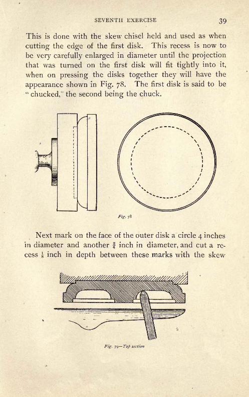
This is done with the skew chisel held and used as when
cutting the edge of the first disk. This recess is now to
be very carefully enlarged in diameter until the projection
that was turned on the first disk will fit tightly into it,
when on pressing the disks together they will have the
appearance shown in Fig. 78. The first disk is said to be"chucked," the second being the chuck.
Fig. 78
Next mark on the face of the outer disk a circle 4 inches
in diameter and another f inch in diameter, and cut a re-
cess i inch in depth between these marks with the skew
ig- 79 Top section
4O WOOD -TURNING
chisel. On the bottom of this recess, i inch from the sides,
make two more circles, and with these as guides cut an-
other recess, of the form shown in Fig. 79, into the disk.
As the sides of this recess are rounded, use the round-nose
chisel to cut it. The round-nose chisel is used as a scrap-
ing tool, as the skew chisel was during this exercise, and its
position when in use is shown in Fig. 79.
Varnish and polish this face also, and then remove it
from the chuck.
EIGHTH EXERCISE
Material. Gum or cherry disk, $' diameter, f" thick.
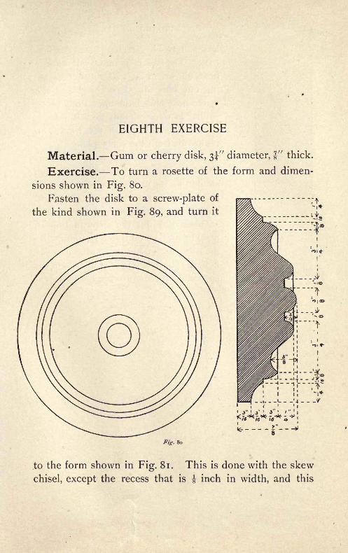
Exercise. To turn a rosette of the form and dimen-
sions shown in Fig. 80.
Fasten the disk to a screw-plate of
the kind shown in Fig. 89, and turn it
Fig. 80
.to the form shown in Fig. 81. This is done with the skew
chisel, except the recess that is J inch in width, and this

WOOD -TURNING
Fig. 8 1
latter may be cut with the parting-tool. The work is next cut to the
form shown in Fig. 80, the curves be-
ing cut with the skew chisel and the
round-nose chisel, the operations beingsimilar to those already performed.
Varnish and polish the work, and
remove it from the screw-plate.
When a number of rosettes of this
character are to be turned, a templet,
similar in its use to that employed in
the Sixth Exercise, may be prepared and
used. Only the principal dimensions,
such as those for the steps in Fig. 81,
need be marked on it, and from these di-
mensions the operator can produce a suf-
ficiently close degree of similarity in the
successive pieces to serve his purpose.
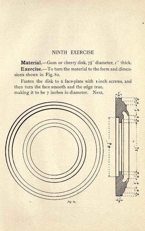
NINTH EXERCISE
Material. Gum or cherry disk, 7^" diameter, i" thick.
Exercise. To turn the material to the form and dimen-
sions shown in Fig. 82.
Fasten the disk to a face-plate with i-inch screws, and
then turn the face smooth and the edge true,
making it to be 7 inches in diameter. Next,
Fig, 82

44 WOOD -TURNING
turn a recess in the face 4! inches in diameter and f inch
in depth, and when this is done remove it from the face-
plate. Put on instead of the disk just turned a pine one
5 inches in diameter, and turn from it a
chuck to fit tightly into the recess turned
in the first disk. Put the disk on the
chuck, and turn its edge to the form shown
in Fig. 83, after which round the fillet to
the form shown by the dotted line, usingthe i-inch skew chisel. Next cut the recess
shown at [A],The curve shown at [b] in Fig. 84 is cut
with the i -inch gouge, used as a scrapingtool. When using a gouge as a scraping
tool, have the cutting portion of the edge
supported on the rest. If, while the gougeis in the position shown in Fig. 85, the cut-
ting is done with the part marked [a], the
tendency will be to press [a] down, and so roll the cut-
ting edge into the work, rendering the edge unmanage-able and tearing the work. Undercut the inner curve
with the i-inch round-nose chisel, held as shown in Fig. 86,
where the manner in which it is supported by the tee rest
is also shown. After the undercut portion has
been turned, round the fillet left on
the inside and then cut the open-
Fig. 83
Fig. 84 Fig. Fig. 86
NINTH EXERCISE 45
ing at the centre through, using the parting-tool. Next cut
the bead around the edge of the disk with the acute corner
of the i-inch skew chisel, using it as a scraping tool. All
'of these cuts are shown in Fig. 86.
Varnish and polish the work, and then remove it from
the chuck.
Turned pieces of this character are used principally in
making wooden patterns for metal castings, and in cabinet
work and the interior finishing of buildings.
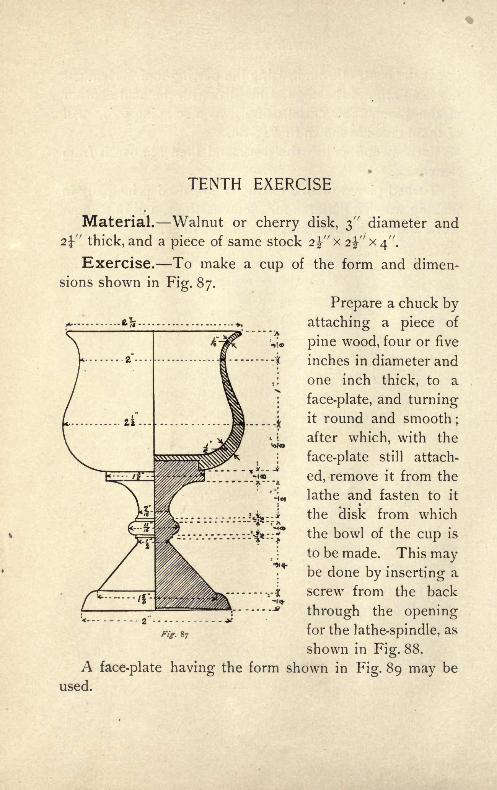
TENTH EXERCISE
Material. Walnut or cherry disk, 3" diameter and
2\" thick, and a piece of same stock 2%" x 2%" x 4".
Exercise. To make a cup of the form and dimen-
sions shown in Fig. 87.
Prepare a chuck by
attaching a piece of
pine wood, four or five
inches in diameter and
one inch thick, to a
face-plate, and turningit round and smooth ;
after which, with the
face-plate still attach-
ed, remove it from the
lathe and fasten to it
the 'disk from which
the bowl of the cup is
to be made. This maybe done by inserting a
screw from the back
through the opening
Ffc g7for the lathe-spindle, as
shown in Fig. 88.
A face-plate having the form shown in Fig. 89 may be
used.

TENTH EXERCISE 47
Turn the outside of the bowl and the recess in the bot-
tom, as shown in Fig. 89, and then re-
move it from the chuck. Next fit the
chuck to the bottom of the bowl, as
shownin
Fig. 90,
and cut
the r e-
cess shown in
the front, usingthe J-inch skew
chisel, andmake the re-
cess if inches
in diameter
and 1 1 inches
deep. Finish the bowl to the form shown in Fig. 91 with
the i-inch round-nose chisel.
Fig- 89
Fig. 91
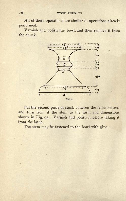
48 WOOD -TURNING
All of these operations are similar to operations already
performed.
Varnish and polish the bowl, and then remove it from
the chuck.
01+
Put the second piece of stock between the lathe-centres,
and turn from it the stem to the form and dimensions
shown in Fig. 92. Varnish and polish it before taking it
from the lathe.
The stem may be fastened to the bowl with glue.
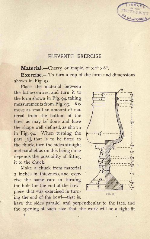
ELEVENTH EXERCISE
Material. Cherry or maple, 2"x2"x8".
Exercise. To turn a cup of the form and dimensions
shown in Fig. 93.
Place the material between
the lathe-centres, and turn it to
the form shown in Fig. 94, taking
measurements from Fig. 93. Re-
move as small an amount of ma-
terial from the bottom of the
bowl as may be done and have
the shape well defined, as shown
in Fig. 94. When turning the
part [a], that is to be fitted to
the chuck, turn the sides straight
and parallel, as on this being done
depends the possibility of fitting
it to the chuck.
Make a chuck from material
2 inches in thickness, and exer-
cise the same care in turningthe hole for the end of the bowl-
piece that was exercised in turn-
ing the end of the bowl- that is,
have the sides parallel and perpendicular to the face, and
the opening of such size that the work will be a tight fit

50 WOOD -TURNING
and not quite reach to the bottom. The shoulder turned
on the bowl-piece ought to rest against the face of the
chuck, as shown in Fig. 96. If it be found on starting the
lathe, after fitting thea
i .K/PTW _ ,
work into the chuck,
that the work runs un-
true, it will be better to
Fig 94fit another chuck rath-
er than try to correct it
When the bowl-piece has been fitted to the chuck so
that it turns true to its axis, cut a small V shaped openingin the centre of the end, as shown in Fig. 95, using the
acute corner of the skew chisel to make it. This openingis used to start a bored hole into the bowl. The
hole may be made with a twist-drill, used as shownj||
in Fig. 96 that is, with the cutting end in the small
opening in the bowl, and the other end in contact
with the cone-centre held in the tail-stock. The bowl, not
the drill, is revolved during the* boring, and this is done
with the driving-belt so placed as to give the slowest speed.
The drill is forced into the wood by advancing the tail-
stock spindle, and is prevented from turning by holding
Fig. 96
its end in a wrench. The depth of hole in the bowl is
measured on the drill, and may be marked before starting
to bore. The inside of the bowl is finished to shape with
the i-inch round-nose chisel used, and supported by the

ELEVENTH EXERCISE 51
tee rest in the manner shown in Fig. 97. It will be found
safer to have the cutting edge a small distance above the
centre of the cup.
Fig- 97
After the inside of the bowl has been finished, turn
the stem to the form shown, without removing the cup from
the chuck, and then varnish and polish it. It may be cut
from the chuck with a parting tool.

TWELFTH EXERCISE
Fig. 98
Material. Maple, 3f xsf'xs".
Exercise. To turn a sphere $\" in diameter.
Care must be taken in the pre-
liminary steps to have the dimen-
sions as given.
Turn the material to the form
and dimensions shown in Fig. 98,
] and with a pencil mark the lines
shown one in the centre first, and
the other two at the same distance
on each side of it. Next, cut the
material to the form shown in Fig. 99, using the outer
lines and the corners at the stem as guides.
Find the centre of
each of the sloping
faces, and then mark
on all three faces the
lines shown in Fig.
99. Next, cut the stem
on which the work is
revolving to a diam-
eter of H inch, as
shown in Fig. 100, and
using the corner where
the stem joins the body Fig, 99
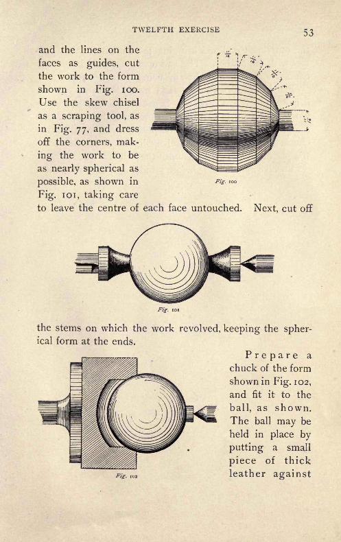
TWELFTH EXERCISE 53
and the lines on the
faces as guides, cut
the work to the form
shown in Fig. 100.
Use the skew chisel
as a scraping tool, as
in Fig. 77, and dress
off the corners, mak-
ing the work to be
as nearly spherical as
possible, as shown in
Fig. 101, taking care
to leave the centre of each face untouched. Next, cut off
Fig. 100
Fig. 101
the stems on which the work revolved, keeping the spher-ical form at the ends.
Prepare a
chuck of the form
shown in Fig. 102,
and fit it to the
ball, as shown.The ball may be
held in place by
putting a small
piece of thick
leather against
54 WOOD -TURNING
the outermost end and bringing the cone-centre into con-
tact with the leather. The ball may be pressed into closer
contact with the chuck by advancing the cone-centre.
Place the ball with its axis in nearly the same position
it had while it was revolving between the centres, and re-
move the eccentric portions with the skew chisel, used as a
scraping tool ;then change the position of the ball in the
chuck by a small amount and again scrape off the eccen-
tric places, and so continue until the ball is a true sphere.
Varnish and polish it before removing it from the chuck.

THIRTEENTH EXERCISE
Material. Pine or poplar, 3*" x JJ-" x 5".
Exercise. To turn a ball 3 inches in diameter.
Turn the material to the form shown in Fig. 98, makingthe two principal dimensions, those of length and diameter,
to be 3 inches. Next, with the skew chisel cut it to the
form shown in Fig. 101, keeping the proper dimension by
frequent use of the calipers.
Turn the ends as small as possible, and then varnish and
polish it, and, when this is done, remove it from the lathe
and cut off the ends with a knife, taking care to preserve
the spherical outline. Next, varnish the ends.
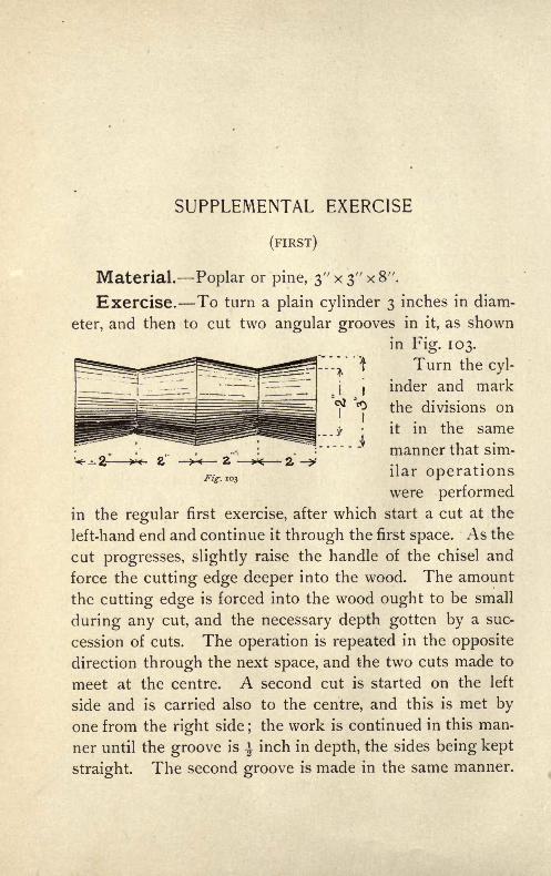
SUPPLEMENTAL EXERCISE
(FIRST)
Material. Poplar or pine, 3//
x3// x8 //
.
Exercise. To turn a plain cylinder 3 inches in diam-
eter, and then to cut two angular grooves in it, as shown
in Fig. 103.
I Turn the cyl-
inder and mark
the divisions on
it in the same
manner that sim-
ilar operationswere performed
in the regular first exercise, after which start a cut at the
left-hand end and continue it through the first space. As the
cut progresses, slightly raise the handle of the chisel and
force the cutting edge deeper into the wood. The amount
the cutting edge is forced into the wood ought to be small
during any cut, and the necessary depth gotten by a suc-
cession of cuts. The operation is repeated in the opposite
direction through the next space, and the two cuts made to
meet at the centre. A second cut is started on the left
side and is carried also to the centre, and this is met by
one from the right side;the work is continued in this man-
ner until the groove is \ inch in depth, the sides being kept
straight. The second groove is made in the same manner.

SUPPLEMENTAL EXERCISE
(SECOND)
12Material. Maple, s^'xs
Exercise. To turn a plain cylinder 3 inches in diam-
eter, and then to cut it to the form shown in Fig. 104.
Fig. 104
The cylinder is turned, the divisions are marked on it,
and the recesses- are cut in the manner the corresponding
operations were performed in the regular second exercise.
This exercise differs from the regular one in having the
recess at the centre larger, and so giving greater likelihood
of vibration if the chisel be pressed too strongly against it.
There is no material difference between the operationsand those already described.

SUPPLEMENTAL EXERCISE
(THIRD)
Material. The turned piece made in the second sup-
plemental exercise.
Exercise. To turn a dumb-bell of the form and di-
mensions shown in Fig. 105.
Turn the handle first, using the |-inch skew chisel, and
make it i inches in diameter andJ-
inch at the sides.
* \Fig. 105
Next, find the centre of each of the larger parts, and mark
it around with a pencil, and, using these centre lines as the
starting-places for cuts, turn each end to the spherical form
shown in Fig. 97, operating in the same manner that the
convex curves were made in the regular third exercise.
Turn the inside first and then the outside, cutting the ball
a small amount inside the'outer corner, that the spherical
SUPPLEMENTAL EXERCISE 59
form may be retained. When the balls have been turned
on each end, the surplus stock outside of them may be cut
off by being first turned quite small in diameter and then
cut off with a knife or chisel.
Though these curves are larger than the curves on
the regular exercise, they will be found more difficult
to cut.
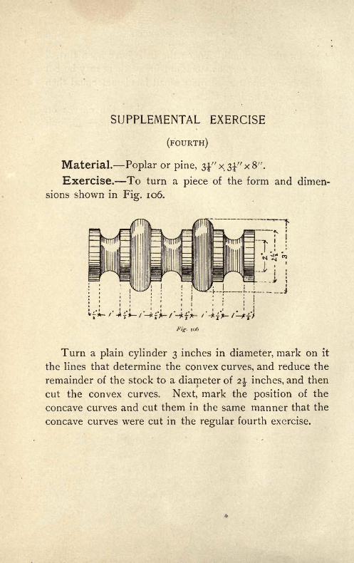
SUPPLEMENTAL EXERCISE
(FOURTH)
Material. Poplar or pine, 33." x 3" x 8".
Exercise. To turn a piece of the form and dimen-
sions shown in Fig. 106.
Fig. 106
Turn a plain cylinder 3 inches in diameter, mark on it
the lines that determine the convex curves, and reduce the
remainder of the stock to a diameter of 2 inches, and then
cut the convex curves. Next, mark the position of the
concave curves and cut them in the same manner that the
concave curves were cut in the regular fourth exercise.

SUPPLEMENTAL EXERCISE
(SIXTH)
Material. Cherry, size determined by the handle se-
lected.
Exercise. To turn one of the handles shown in
Fig. 107.
Use only the principal dimensions that is, the length,
largest diameter, and
size of ferrule on the
end. The remainingdimensions to be taken Fig. io7
as a matter of judg-
ment, and to be such that the handle will have the ap-
pearance shown. In the screw-driver handle the octagonal
Fig. 107 Fig. 107
portion is made by leaving that part untouched during the
turning and afterwards planing off the corners.
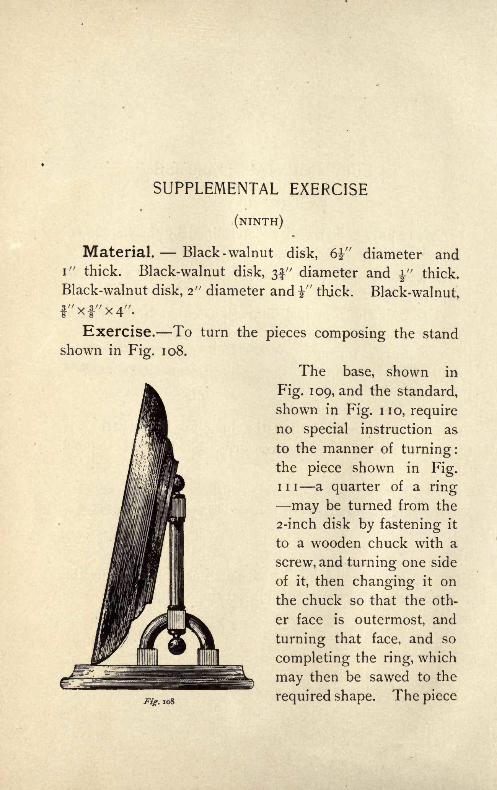
SUPPLEMENTAL EXERCISE
(NINTH)
Material. -- Black -walnut disk, 6i" diameter andi" thick. Black-walnut disk, 3f" diameter and y
f
thick.
Black-walnut disk, 2" diameter and"thick. Black-walnut,
f"xf'X4".
Exercise. To turn the pieces composing the stand
shown in Fig. 108.
The base, shown in
Fig. 109, and the standard,
shown in Fig. no, requireno special instruction as
to the manner of turning:the piece shown in Fig.in a quarter of a ring
may be turned from the
2-inch disk by fastening it
to a wooden chuck with a
screw, and turning one side
of it, then changing it on
the chuck so that the oth-
er face is outermost, and
turning that face, and so
completing the ring, which
may then be sawed to the
108 required shape. The piece

SUPPLEMENTAL EXERCISE
shown in Fig. 113 is
made from the larger
disk by fastening it
to a face-plate or to
a wooden chuck and
turning the back, then
turning it over and
fastening it to the
same plate or chuck
by screws that do not
pass quite through it,
and then cutting the
front side, using the
same methods for get-
ting the proper form that were used in the regular sixth
exercise. The holes left in the back by the screws used
Fig io9
CEOFig. no
Fig. in Fig. 112
to hold it to the chuck may be filled with small plugs of the
same material as that of which the piece is composed. The
Fig. 113

64 WOOD-TURNING
pieces shown in Fig. 112 are glued in place, as are also
the other pieces.
Fig. 114 Front
Where turned work is used in the construction of house
furniture, this method of turning the parts separately and
then fastening them together is freely used. An illustration
of combined sawed and turned work is shown in Fig. 114.

SUPPLEMENTAL EXERCISE
(ELEVENTH)
Material. Cherry, 3" x 3" x 8".
Exercise. To turn a vase of the form and dimensions
shown in Fig. 1 1 5 and Fig. 1 1 6.
Turn the outside and fit it to a wooden chuck in the
Fig. 115 Fig. 116
same inanner that similar operations were performed
during the regular eleventh exercise. The inside may be
*bored and then turned with the round-nose chisel, or the
work may be done wholly with the skew -chisel. Theskew-chisel may be used to finish the square corners.
Varnish and polish it before removing it from the chuck.
5

SUPPLEMENTAL EXERCISE
(TWELFTH)
Material. A sphere turned as in the ninth exercise.
Exercise. To turn a ball inside the one alreadyturned.
Fig. 117
Over the wooden chuck used in turning the ball fit a
wooden disk, and turn a hole in the centre of it, so that it maybe fastened to the chuck with screws, and have a portion of
t _^, .--__.-
= the ball project through the
front, as shown in Fig. 1 1 7.
The fit 'to the ball must be
close, so that the ball will be
held firmly in any required
position.

SUPPLEMENTAL EXERCISE
Procure two tools of the form shown in Fig. 1 18 and Fig.
119. The curvature of
the end must be the
same as that of the in-
side ball. These maybe made from old files
by grinding.
Mark the extremities
of the three axes of the sphere that are perpendicular to one
another. This may be done by setting the sphere in a corner
of a square box and marking the
points of contact, and then finding
a point on the sphere opposite each
one of the three so found by means
of the calipers. When the points
are found, fasten the sphere in place
in the chuck in such position that
one of the points is exactly in the
centre of the opening in the diskFig. 120 r O
that covers the chuck, and with the
tool shown in Fig. 118 cut a hole into the ball in the man-
Fig. 121

68 WOOD-TURNING
Fig. 122
the six marks
ner shown in Fig. 117. The depthof the hole should be inch, and
this may be regulated by makinga mark on the corner of the chisel
before starting the cut. Next, loosen
the front part of the chuck and
move the ball until a second markis in the centre of the opening, and
cut in again, and so continue until
have been used and the ball has the ap-
Fig. 123

SUPPLEMENTAL EXERCISE 69
pearance shown in Fig. 120. Now, using the second tool
in the manner shown in Fig. 121, remove the material be-
tween the holes so cut until the inner ball is free from
the outer shell, as shown in Fig. 122. The last cut taken
must be made with great care, or the freed inner ball will
catch on the tool and break the outer shell. The lathe-
spindle would better be revolved by hand during the latter
portion of the cut.
This is but one of many solids that may be turned
inside the sphere in nearly the manner indicated, and the
turning of which is most fascinating work for a skilful
turner.
THE END