wood turning duplicatordescription for assembly to your particular wood lathe. fig. 2 the 46-408...
TRANSCRIPT
INS
TRU
CTIO
NM
AN
UA
L
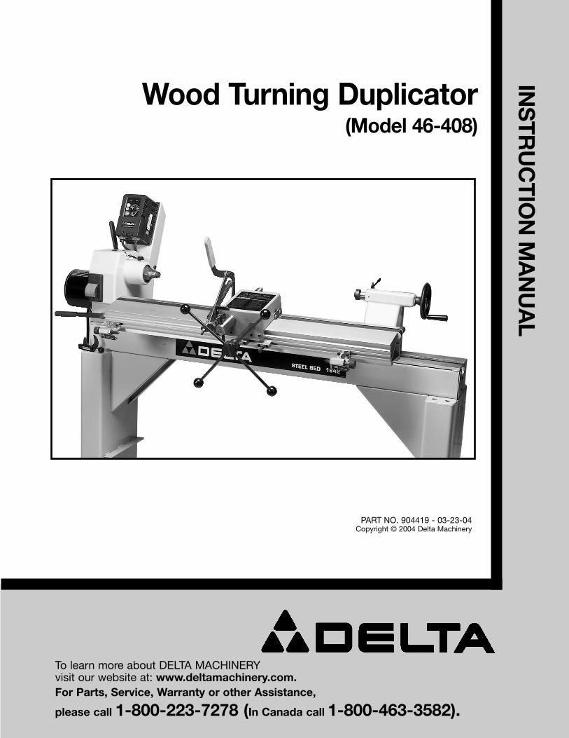
Wood Turning Duplicator(Model 46-408)
PART NO. 904419 - 03-23-04Copyright © 2004 Delta Machinery
To learn more about DELTA MACHINERY visit our website at: www.deltamachinery.com.For Parts, Service, Warranty or other Assistance,
please call 1-800-223-7278 (In Canada call 1-800-463-3582).
2
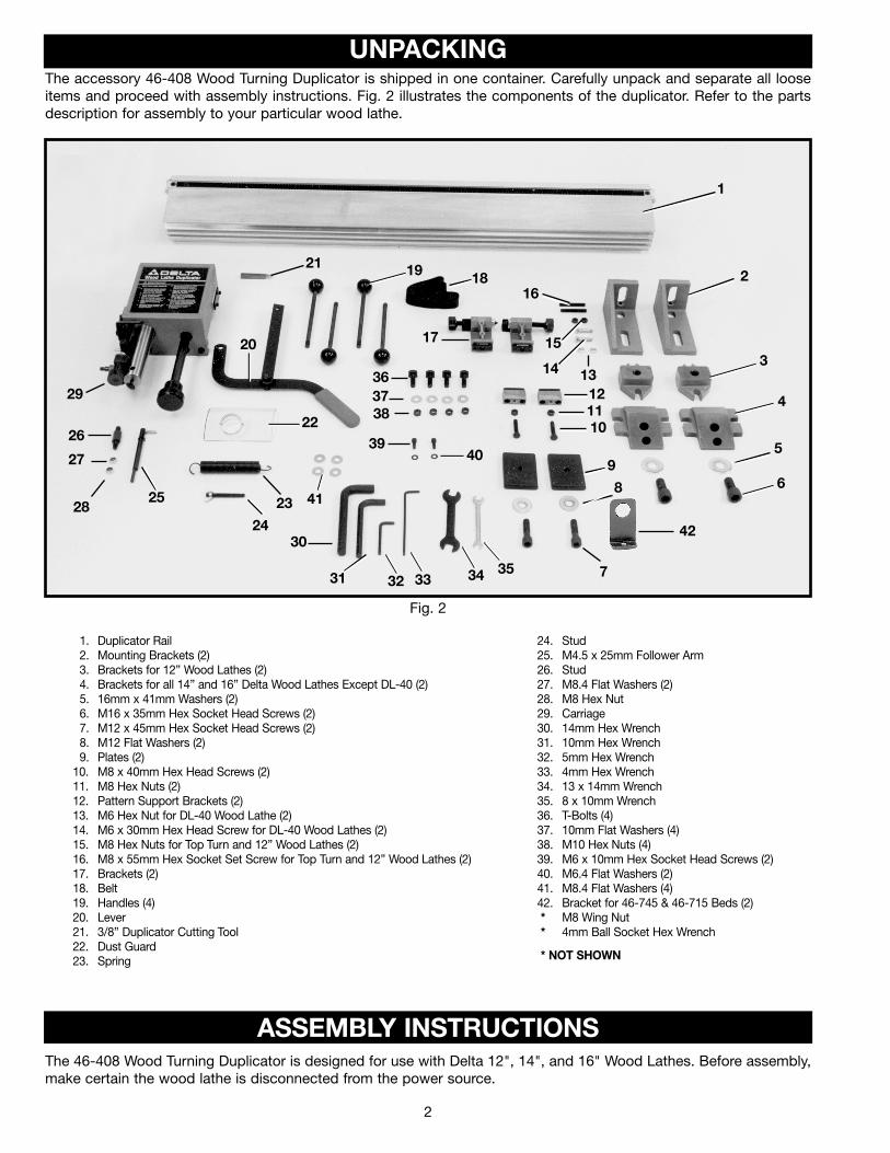
The accessory 46-408 Wood Turning Duplicator is shipped in one container. Carefully unpack and separate all looseitems and proceed with assembly instructions. Fig. 2 illustrates the components of the duplicator. Refer to the partsdescription for assembly to your particular wood lathe.
Fig. 2
The 46-408 Wood Turning Duplicator is designed for use with Delta 12", 14", and 16" Wood Lathes. Before assembly,make certain the wood lathe is disconnected from the power source.
1. Duplicator Rail2. Mounting Brackets (2)3. Brackets for 12” Wood Lathes (2)4. Brackets for all 14” and 16” Delta Wood Lathes Except DL-40 (2)5. 16mm x 41mm Washers (2)6. M16 x 35mm Hex Socket Head Screws (2)7. M12 x 45mm Hex Socket Head Screws (2)8. M12 Flat Washers (2)9. Plates (2)
10. M8 x 40mm Hex Head Screws (2)11. M8 Hex Nuts (2)12. Pattern Support Brackets (2)13. M6 Hex Nut for DL-40 Wood Lathe (2)14. M6 x 30mm Hex Head Screw for DL-40 Wood Lathes (2)15. M8 Hex Nuts for Top Turn and 12” Wood Lathes (2)16. M8 x 55mm Hex Socket Set Screw for Top Turn and 12” Wood Lathes (2)17. Brackets (2)18. Belt19. Handles (4)20. Lever21. 3/8” Duplicator Cutting Tool22. Dust Guard23. Spring
24. Stud25. M4.5 x 25mm Follower Arm26. Stud27. M8.4 Flat Washers (2)28. M8 Hex Nut29. Carriage30. 14mm Hex Wrench31. 10mm Hex Wrench32. 5mm Hex Wrench33. 4mm Hex Wrench34. 13 x 14mm Wrench35. 8 x 10mm Wrench36. T-Bolts (4)37. 10mm Flat Washers (4)38. M10 Hex Nuts (4)39. M6 x 10mm Hex Socket Head Screws (2)40. M6.4 Flat Washers (2)41. M8.4 Flat Washers (4)42. Bracket for 46-745 & 46-715 Beds (2) * M8 Wing Nut* 4mm Ball Socket Hex Wrench
* NOT SHOWN
1
2
3
4
5
6
7
8
9
101112
17
1816
15
1314
1921
20
22
29
26
27
2825
24
23 41
363738
3940
3534
30
31 32 33
42
ASSEMBLY INSTRUCTIONS
UNPACKING
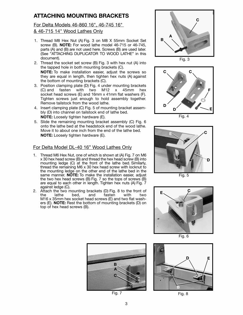
ATTACHING MOUNTING BRACKETS
For Delta Models 46-860 16", 46-745 16" & 46-715 14" Wood Lathes Only
1. Thread M8 Hex Nut (A) Fig. 3 on M8 X 55mm Socket Setscrew (B). NOTE: For wood lathe model 46-715 or 46-745,parts (A) and (B) are not used here. Screws (B) are used later.(See ”ATTACHING DUPLICATOR TO WOOD LATHE” in thisdocument).
2. Thread the socket set screw (B) Fig. 3 with hex nut (A) intothe tapped hole in both mounting brackets (C). NOTE: To make installation easier, adjust the screws sothey are equal in length, then tighten hex nuts (A) againstthe bottom of mounting brackets (C).
3. Position clamping plate (D) Fig. 4 under mounting brackets(C) and fasten with two M12 x 45mm hexsocket head screws (E) and 16mm x 41mm flat washers (F).Tighten screws just enough to hold assembly together.Remove tailstock from the wood lathe.
4. Insert clamping plate (C) Fig. 5 of mounting bracket assem-bly (D) into channel on tailstock end of lathe bed. NOTE: Loosely tighten hardware (E).
5. Slide the remaining mounting bracket assembly (C) Fig. 6onto the lathe bed at the headstock end of the wood lathe.Move it to about one inch from the end of the lathe bed.NOTE: Loosely tighten hardware (E).
3
Fig. 3
Fig. 4
Fig. 5
Fig. 6
C
BA
DD E
F
CC
E C
D
E C
BA
C
Fig. 7 Fig. 8
D E
B
For Delta Model DL-40 16” Wood Lathes Only
1. Thread M6 Hex Nut, one of which is shown at (A) Fig. 7 on M6x 30 hex head screw (B) and thread the hex head screw (B) intomounting ledge (C) at the front of the lathe bed. Similarly,thread the remaining M6 x 30 hex head screw with locknut tothe mounting ledge on the other end of the lathe bed in thesame manner. NOTE: To make the installation easier, adjustthe two hex head screws (B) Fig. 7 so the tops of screws (B)are equal to each other in length. Tighten hex nuts (A) Fig. 7against ledge (C).
2. Attach the two mounting brackets (D) Fig. 8 to the front ofthe lathe bed, and fasten with twoM16 x 35mm hex socket head screws (E) and two flat wash-ers (E). NOTE: Rest the bottom of mounting brackets (D) ontop of hex head screws (B).
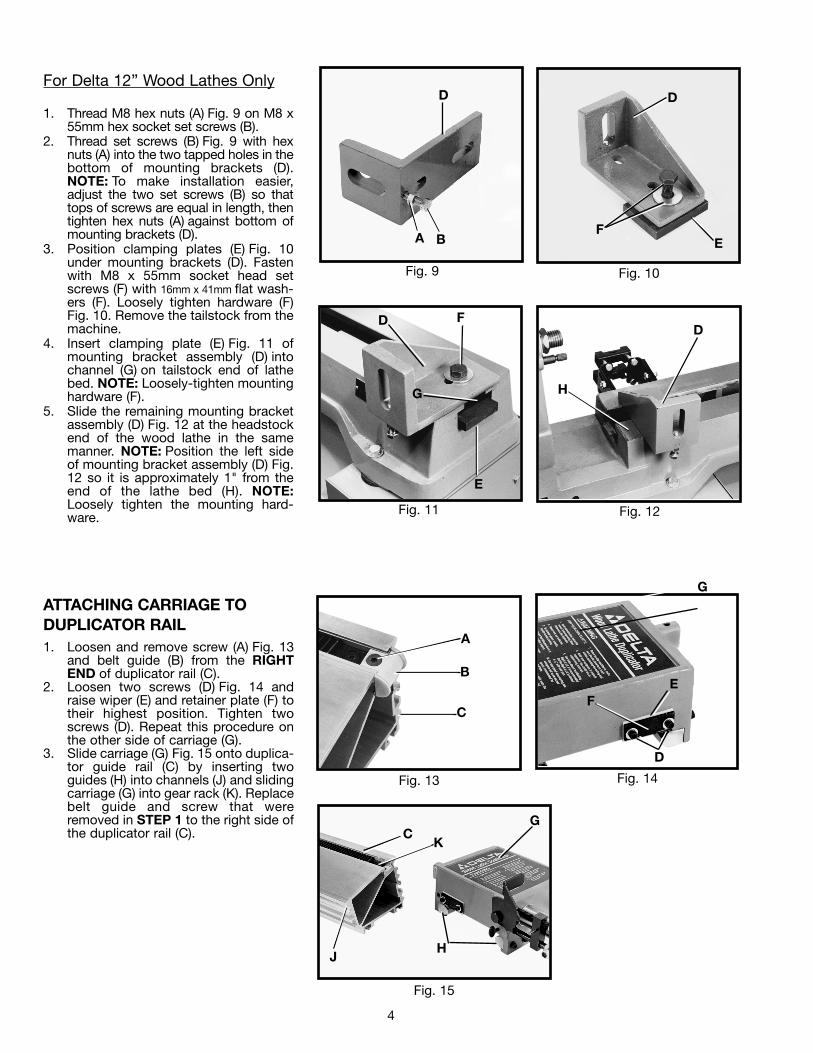
For Delta 12” Wood Lathes Only
1. Thread M8 hex nuts (A) Fig. 9 on M8 x55mm hex socket set screws (B).
2. Thread set screws (B) Fig. 9 with hexnuts (A) into the two tapped holes in thebottom of mounting brackets (D).NOTE: To make installation easier,adjust the two set screws (B) so thattops of screws are equal in length, thentighten hex nuts (A) against bottom ofmounting brackets (D).
3. Position clamping plates (E) Fig. 10under mounting brackets (D). Fastenwith M8 x 55mm socket head setscrews (F) with 16mm x 41mm flat wash-ers (F). Loosely tighten hardware (F)Fig. 10. Remove the tailstock from themachine.
4. Insert clamping plate (E) Fig. 11 ofmounting bracket assembly (D) intochannel (G) on tailstock end of lathebed. NOTE: Loosely-tighten mountinghardware (F).
5. Slide the remaining mounting bracketassembly (D) Fig. 12 at the headstockend of the wood lathe in the samemanner. NOTE: Position the left sideof mounting bracket assembly (D) Fig.12 so it is approximately 1" from theend of the lathe bed (H). NOTE:Loosely tighten the mounting hard-ware.
4
Fig. 11 Fig. 12
Fig. 13 Fig. 14
ATTACHING CARRIAGE TODUPLICATOR RAIL1. Loosen and remove screw (A) Fig. 13
and belt guide (B) from the RIGHTEND of duplicator rail (C).
2. Loosen two screws (D) Fig. 14 andraise wiper (E) and retainer plate (F) totheir highest position. Tighten twoscrews (D). Repeat this procedure onthe other side of carriage (G).
3. Slide carriage (G) Fig. 15 onto duplica-tor guide rail (C) by inserting twoguides (H) into channels (J) and slidingcarriage (G) into gear rack (K). Replacebelt guide and screw that wereremoved in STEP 1 to the right side ofthe duplicator rail (C).
D F
G
E
D
H
A
B
C
G
EF
D
Fig. 9 Fig. 10
D
A B EF
D
Fig. 15
J
KC
G
H
5
Fig. 16 Fig. 17
Fig. 18
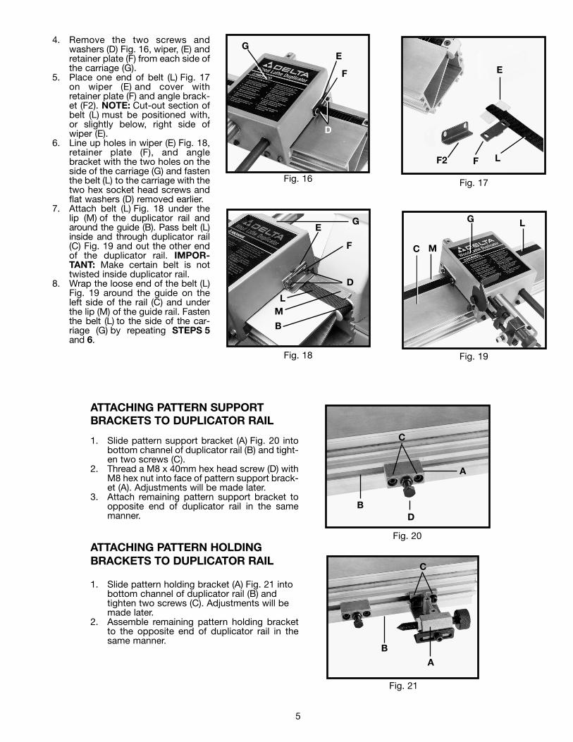
4. Remove the two screws andwashers (D) Fig. 16, wiper, (E) andretainer plate (F) from each side ofthe carriage (G).
5. Place one end of belt (L) Fig. 17on wiper (E) and cover withretainer plate (F) and angle brack-et (F2). NOTE: Cut-out section ofbelt (L) must be positioned with,or slightly below, right side ofwiper (E).
6. Line up holes in wiper (E) Fig. 18,retainer plate (F), and anglebracket with the two holes on theside of the carriage (G) and fastenthe belt (L) to the carriage with thetwo hex socket head screws andflat washers (D) removed earlier.
7. Attach belt (L) Fig. 18 under thelip (M) of the duplicator rail andaround the guide (B). Pass belt (L)inside and through duplicator rail(C) Fig. 19 and out the other endof the duplicator rail. IMPOR-TANT: Make certain belt is nottwisted inside duplicator rail.
8. Wrap the loose end of the belt (L)Fig. 19 around the guide on theleft side of the rail (C) and underthe lip (M) of the guide rail. Fastenthe belt (L) to the side of the car-riage (G) by repeating STEPS 5and 6.
G
F
E
D
E
F L
G
F
E
D
L
B
M
Fig. 19
C
L
M
G
Fig. 20
Fig. 21
ATTACHING PATTERN SUPPORT BRACKETS TO DUPLICATOR RAIL
1. Slide pattern support bracket (A) Fig. 20 intobottom channel of duplicator rail (B) and tight-en two screws (C).
2. Thread a M8 x 40mm hex head screw (D) withM8 hex nut into face of pattern support brack-et (A). Adjustments will be made later.
3. Attach remaining pattern support bracket toopposite end of duplicator rail in the samemanner.
ATTACHING PATTERN HOLDING BRACKETS TO DUPLICATOR RAIL
1. Slide pattern holding bracket (A) Fig. 21 intobottom channel of duplicator rail (B) andtighten two screws (C). Adjustments will bemade later.
2. Assemble remaining pattern holding bracketto the opposite end of duplicator rail in thesame manner.
C
A
DB
C
B
A
F2
ATTACHING FOLLOWER ARM TO CARRIAGE ASSEMBLY
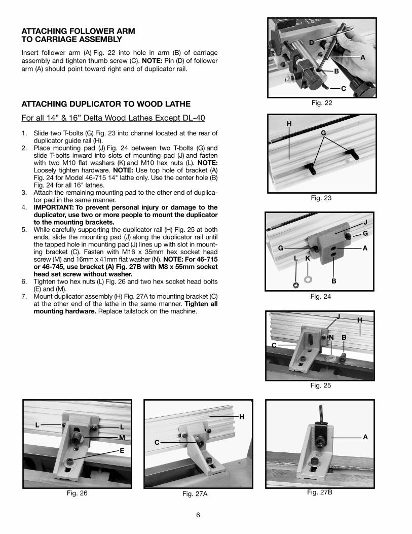
Insert follower arm (A) Fig. 22 into hole in arm (B) of carriageassembly and tighten thumb screw (C). NOTE: Pin (D) of followerarm (A) should point toward right end of duplicator rail.
6
ATTACHING DUPLICATOR TO WOOD LATHE
For all 14” & 16” Delta Wood Lathes Except DL-40
1. Slide two T-bolts (G) Fig. 23 into channel located at the rear ofduplicator guide rail (H).
2. Place mounting pad (J) Fig. 24 between two T-bolts (G) andslide T-bolts inward into slots of mounting pad (J) and fastenwith two M10 flat washers (K) and M10 hex nuts (L). NOTE:Loosely tighten hardware. NOTE: Use top hole of bracket (A)Fig. 24 for Model 46-715 14" lathe only. Use the center hole (B)Fig. 24 for all 16" lathes.
3. Attach the remaining mounting pad to the other end of duplica-tor pad in the same manner.
4. IMPORTANT: To prevent personal injury or damage to theduplicator, use two or more people to mount the duplicatorto the mounting brackets.
5. While carefully supporting the duplicator rail (H) Fig. 25 at bothends, slide the mounting pad (J) along the duplicator rail untilthe tapped hole in mounting pad (J) lines up with slot in mount-ing bracket (C). Fasten with M16 x 35mm hex socket headscrew (M) and 16mm x 41mm flat washer (N). NOTE: For 46-715or 46-745, use bracket (A) Fig. 27B with M8 x 55mm sockethead set screw without washer.
6. Tighten two hex nuts (L) Fig. 26 and two hex socket head bolts(E) and (M).
7. Mount duplicator assembly (H) Fig. 27A to mounting bracket (C)at the other end of the lathe in the same manner. Tighten allmounting hardware. Replace tailstock on the machine.
Fig. 22
Fig. 23
Fig. 24
Fig. 25
Fig. 26 Fig. 27A Fig. 27B
C
B
A
D
A
B
G
KL
GH
C
J H
N B
LL
M
EC
H
A
J
G
7
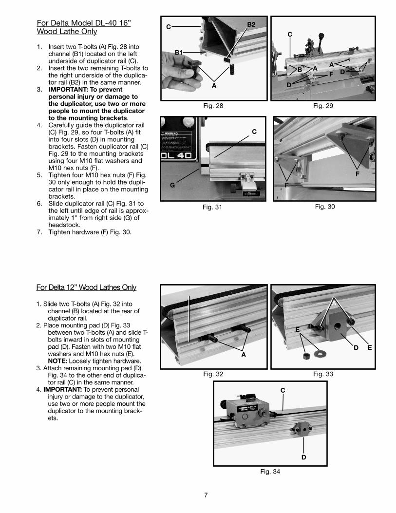
For Delta Model DL-40 16”Wood Lathe Only
1. Insert two T-bolts (A) Fig. 28 intochannel (B1) located on the leftunderside of duplicator rail (C).
2. Insert the two remaining T-bolts tothe right underside of the duplica-tor rail (B2) in the same manner.
3. IMPORTANT: To prevent personal injury or damage tothe duplicator, use two or morepeople to mount the duplicatorto the mounting brackets.
4. Carefully guide the duplicator rail(C) Fig. 29, so four T-bolts (A) fitinto four slots (D) in mountingbrackets. Fasten duplicator rail (C)Fig. 29 to the mounting bracketsusing four M10 flat washers andM10 hex nuts (F).
5. Tighten four M10 hex nuts (F) Fig.30 only enough to hold the dupli-cator rail in place on the mountingbrackets.
6. Slide duplicator rail (C) Fig. 31 tothe left until edge of rail is approx-imately 1" from right side (G) ofheadstock.
7. Tighten hardware (F) Fig. 30.
Fig. 28 Fig. 29
Fig. 30Fig. 31
For Delta 12” Wood Lathes Only
1. Slide two T-bolts (A) Fig. 32 intochannel (B) located at the rear ofduplicator rail.
2. Place mounting pad (D) Fig. 33between two T-bolts (A) and slide T-bolts inward in slots of mountingpad (D). Fasten with two M10 flatwashers and M10 hex nuts (E).NOTE: Loosely tighten hardware.
3. Attach remaining mounting pad (D)Fig. 34 to the other end of duplica-tor rail (C) in the same manner.
4. IMPORTANT: To prevent personalinjury or damage to the duplicator,use two or more people mount theduplicator to the mounting brack-ets.
Fig. 32 Fig. 33
Fig. 34
C
B1
A
C
B A
D
FA
D
F
F
F
G
C
B
A
A
ED
E
C
D
B2
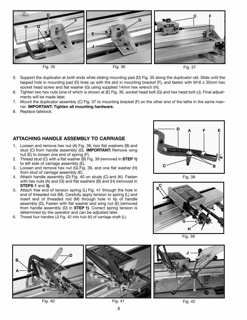
ATTACHING HANDLE ASSEMBLY TO CARRIAGE1. Loosen and remove hex nut (A) Fig. 38, two flat washers (B) and
stud (C) from handle assembly (D). IMPORTANT: Remove wingnut (E) to loosen one end of spring (F).
2. Thread stud (C) with a flat washer (B) Fig. 39 (removed in STEP 1)to left side of carriage assembly (E).
3. Loosen and remove hex nut (G) Fig. 39, and one flat washer (H)from stud of carriage assembly (E).
4. Attach handle assembly (D) Fig. 40 on studs (C) and (K). Fastenwith hex nuts (A) and (G) and flat washers (B) and (H) (removed inSTEPS 1 and 3).
5. Attach free end of tension spring (L) Fig. 41 through the hole inend of threaded rod (M). Carefully apply tension to spring (L) andinsert end of threaded rod (M) through hole in lip of handleassembly (D). Fasten with flat washer and wing nut (E) (removedfrom handle assembly (D) in STEP 1). Correct spring tension isdetermined by the operator and can be adjusted later.
6. Thread four handles (J) Fig. 42 into hub (K) of carriage shaft (L).
8
5. Support the duplicator at both ends while sliding mounting pad (D) Fig. 35 along the duplicator rail. Slide until thetapped hole in mounting pad (D) lines up with the slot in mounting bracket (F), and fasten with M16 x 35mm hexsocket head screw and flat washer (G) using supplied 14mm hex wrench (H).
6. Tighten two hex nuts (one of which is shown at (E) Fig. 36, socket head bolt (G) and hex head bolt (J). Final adjust-ments will be made later.
7. Mount the duplicator assembly (C) Fig. 37 to mounting bracket (F) on the other end of the lathe in the same man-ner. IMPORTANT: Tighten all mounting hardware.
8. Replace tailstock.
Fig. 35 Fig. 36 Fig. 37
Fig. 38
Fig. 39
Fig. 40 Fig. 41 Fig. 42
H G
DF
E
G
J
C F
D A F E
BC
BC
E
G
H
C
A
BD
KG
H LK
M
D E
J
L
K
9
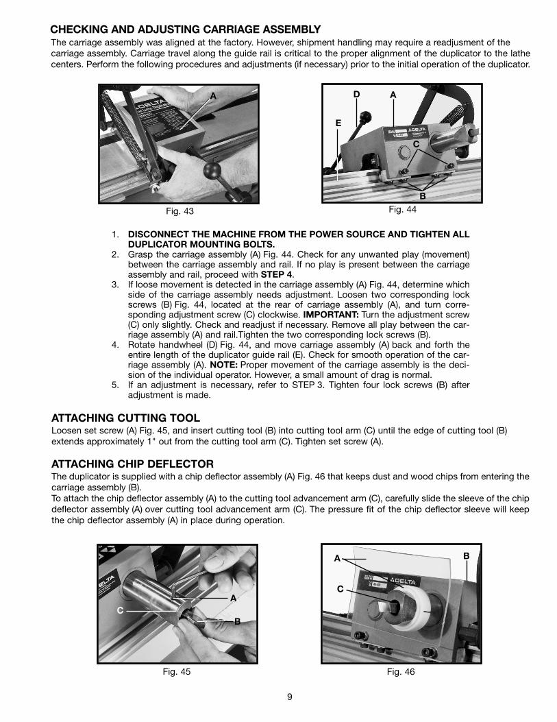
The carriage assembly was aligned at the factory. However, shipment handling may require a readjusment of the carriage assembly. Carriage travel along the guide rail is critical to the proper alignment of the duplicator to the lathecenters. Perform the following procedures and adjustments (if necessary) prior to the initial operation of the duplicator.
1. DISCONNECT THE MACHINE FROM THE POWER SOURCE AND TIGHTEN ALLDUPLICATOR MOUNTING BOLTS.
2. Grasp the carriage assembly (A) Fig. 44. Check for any unwanted play (movement)between the carriage assembly and rail. If no play is present between the carriageassembly and rail, proceed with STEP 4.
3. If loose movement is detected in the carriage assembly (A) Fig. 44, determine whichside of the carriage assembly needs adjustment. Loosen two corresponding lockscrews (B) Fig. 44, located at the rear of carriage assembly (A), and turn corre-sponding adjustment screw (C) clockwise. IMPORTANT: Turn the adjustment screw(C) only slightly. Check and readjust if necessary. Remove all play between the car-riage assembly (A) and rail.Tighten the two corresponding lock screws (B).
4. Rotate handwheel (D) Fig. 44, and move carriage assembly (A) back and forth theentire length of the duplicator guide rail (E). Check for smooth operation of the car-riage assembly (A). NOTE: Proper movement of the carriage assembly is the deci-sion of the individual operator. However, a small amount of drag is normal.
5. If an adjustment is necessary, refer to STEP 3. Tighten four lock screws (B) afteradjustment is made.
Fig. 43 Fig. 44
A
CHECKING AND ADJUSTING CARRIAGE ASSEMBLY
ATTACHING CUTTING TOOLLoosen set screw (A) Fig. 45, and insert cutting tool (B) into cutting tool arm (C) until the edge of cutting tool (B)extends approximately 1" out from the cutting tool arm (C). Tighten set screw (A).
ATTACHING CHIP DEFLECTORThe duplicator is supplied with a chip deflector assembly (A) Fig. 46 that keeps dust and wood chips from entering thecarriage assembly (B).To attach the chip deflector assembly (A) to the cutting tool advancement arm (C), carefully slide the sleeve of the chipdeflector assembly (A) over cutting tool advancement arm (C). The pressure fit of the chip deflector sleeve will keepthe chip deflector assembly (A) in place during operation.
Fig. 45 Fig. 46
E
D A
C
B
CA
B
C
A B
10
ALIGNING DUPLICATOR TO THE LATHE
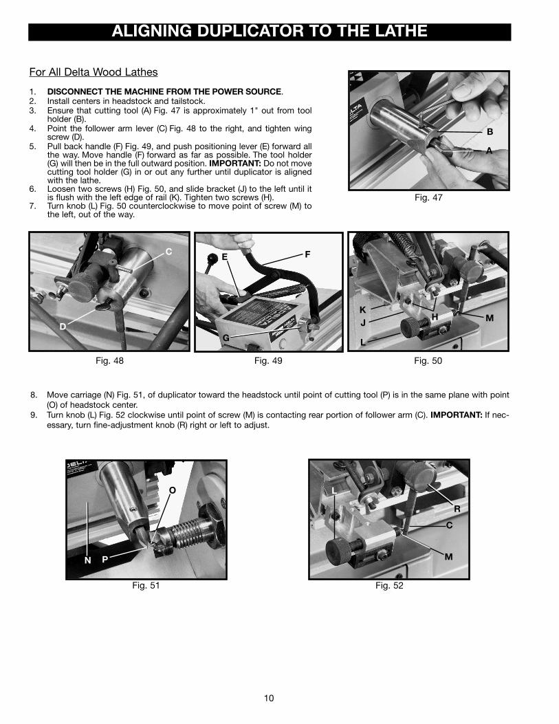
For All Delta Wood Lathes
1. DISCONNECT THE MACHINE FROM THE POWER SOURCE.2. Install centers in headstock and tailstock.3. Ensure that cutting tool (A) Fig. 47 is approximately 1" out from tool
holder (B).4. Point the follower arm lever (C) Fig. 48 to the right, and tighten wing
screw (D).5. Pull back handle (F) Fig. 49, and push positioning lever (E) forward all
the way. Move handle (F) forward as far as possible. The tool holder(G) will then be in the full outward position. IMPORTANT: Do not movecutting tool holder (G) in or out any further until duplicator is alignedwith the lathe.
6. Loosen two screws (H) Fig. 50, and slide bracket (J) to the left until itis flush with the left edge of rail (K). Tighten two screws (H).
7. Turn knob (L) Fig. 50 counterclockwise to move point of screw (M) tothe left, out of the way.
Fig. 48 Fig. 49 Fig. 50
Fig. 47
8. Move carriage (N) Fig. 51, of duplicator toward the headstock until point of cutting tool (P) is in the same plane with point(O) of headstock center.
9. Turn knob (L) Fig. 52 clockwise until point of screw (M) is contacting rear portion of follower arm (C). IMPORTANT: If nec-essary, turn fine-adjustment knob (R) right or left to adjust.
Fig. 51 Fig. 52
B
A
C
D
FE
L
JK
H M
N P
O L
M
C
R
G
11
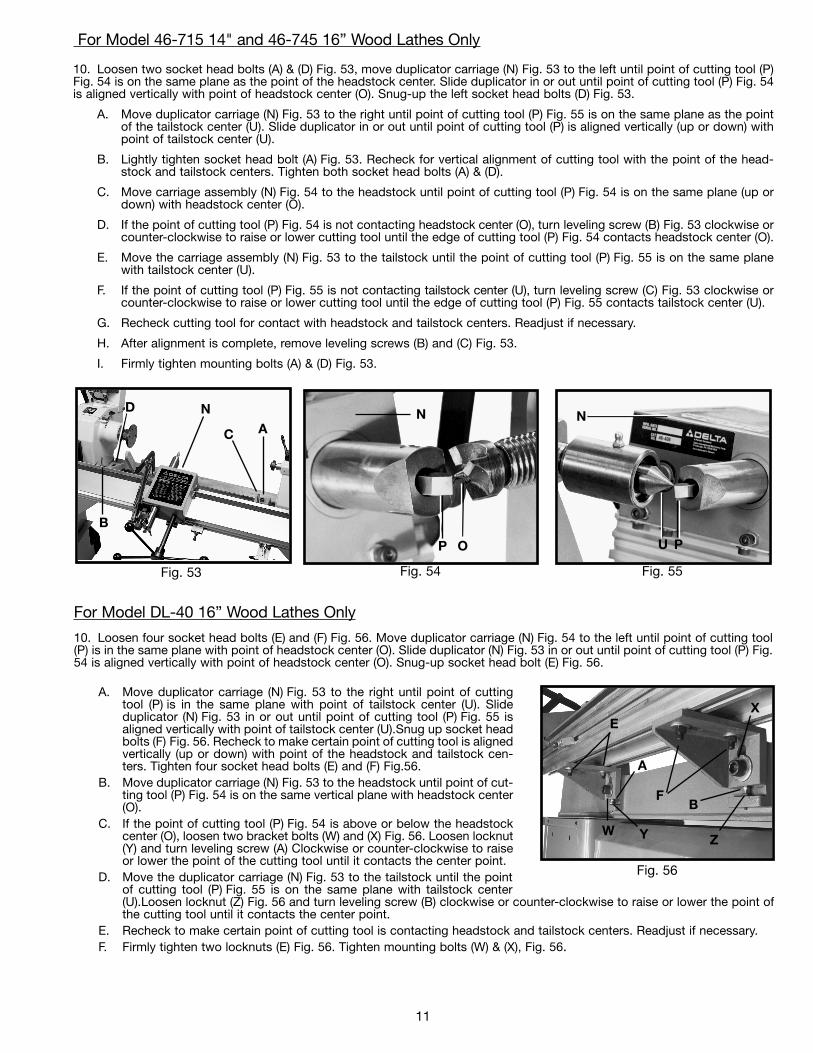
For Model 46-715 14" and 46-745 16” Wood Lathes Only
10. Loosen two socket head bolts (A) & (D) Fig. 53, move duplicator carriage (N) Fig. 53 to the left until point of cutting tool (P)Fig. 54 is on the same plane as the point of the headstock center. Slide duplicator in or out until point of cutting tool (P) Fig. 54is aligned vertically with point of headstock center (O). Snug-up the left socket head bolts (D) Fig. 53.
A. Move duplicator carriage (N) Fig. 53 to the right until point of cutting tool (P) Fig. 55 is on the same plane as the pointof the tailstock center (U). Slide duplicator in or out until point of cutting tool (P) is aligned vertically (up or down) withpoint of tailstock center (U).
B. Lightly tighten socket head bolt (A) Fig. 53. Recheck for vertical alignment of cutting tool with the point of the head-stock and tailstock centers. Tighten both socket head bolts (A) & (D).
C. Move carriage assembly (N) Fig. 54 to the headstock until point of cutting tool (P) Fig. 54 is on the same plane (up ordown) with headstock center (O).
D. If the point of cutting tool (P) Fig. 54 is not contacting headstock center (O), turn leveling screw (B) Fig. 53 clockwise orcounter-clockwise to raise or lower cutting tool until the edge of cutting tool (P) Fig. 54 contacts headstock center (O).
E. Move the carriage assembly (N) Fig. 53 to the tailstock until the point of cutting tool (P) Fig. 55 is on the same planewith tailstock center (U).
F. If the point of cutting tool (P) Fig. 55 is not contacting tailstock center (U), turn leveling screw (C) Fig. 53 clockwise orcounter-clockwise to raise or lower cutting tool until the edge of cutting tool (P) Fig. 55 contacts tailstock center (U).
G. Recheck cutting tool for contact with headstock and tailstock centers. Readjust if necessary.
H. After alignment is complete, remove leveling screws (B) and (C) Fig. 53.
I. Firmly tighten mounting bolts (A) & (D) Fig. 53.
Fig. 54 Fig. 55Fig. 53
For Model DL-40 16” Wood Lathes Only
10. Loosen four socket head bolts (E) and (F) Fig. 56. Move duplicator carriage (N) Fig. 54 to the left until point of cutting tool(P) is in the same plane with point of headstock center (O). Slide duplicator (N) Fig. 53 in or out until point of cutting tool (P) Fig.54 is aligned vertically with point of headstock center (O). Snug-up socket head bolt (E) Fig. 56.
N
P O
N
U P
A. Move duplicator carriage (N) Fig. 53 to the right until point of cuttingtool (P) is in the same plane with point of tailstock center (U). Slideduplicator (N) Fig. 53 in or out until point of cutting tool (P) Fig. 55 isaligned vertically with point of tailstock center (U).Snug up socket headbolts (F) Fig. 56. Recheck to make certain point of cutting tool is alignedvertically (up or down) with point of the headstock and tailstock cen-ters. Tighten four socket head bolts (E) and (F) Fig.56.
B. Move duplicator carriage (N) Fig. 53 to the headstock until point of cut-ting tool (P) Fig. 54 is on the same vertical plane with headstock center(O).
C. If the point of cutting tool (P) Fig. 54 is above or below the headstockcenter (O), loosen two bracket bolts (W) and (X) Fig. 56. Loosen locknut(Y) and turn leveling screw (A) Clockwise or counter-clockwise to raiseor lower the point of the cutting tool until it contacts the center point.
D. Move the duplicator carriage (N) Fig. 53 to the tailstock until the pointof cutting tool (P) Fig. 55 is on the same plane with tailstock center(U).Loosen locknut (Z) Fig. 56 and turn leveling screw (B) clockwise or counter-clockwise to raise or lower the point ofthe cutting tool until it contacts the center point.
E. Recheck to make certain point of cutting tool is contacting headstock and tailstock centers. Readjust if necessary.F. Firmly tighten two locknuts (E) Fig. 56. Tighten mounting bolts (W) & (X), Fig. 56.
Fig. 56
F
E
W
X
A
D N
B
C
Y
A
B
Z
12
Fig. 61
Fig. 62 Fig. 63
Fig. 60
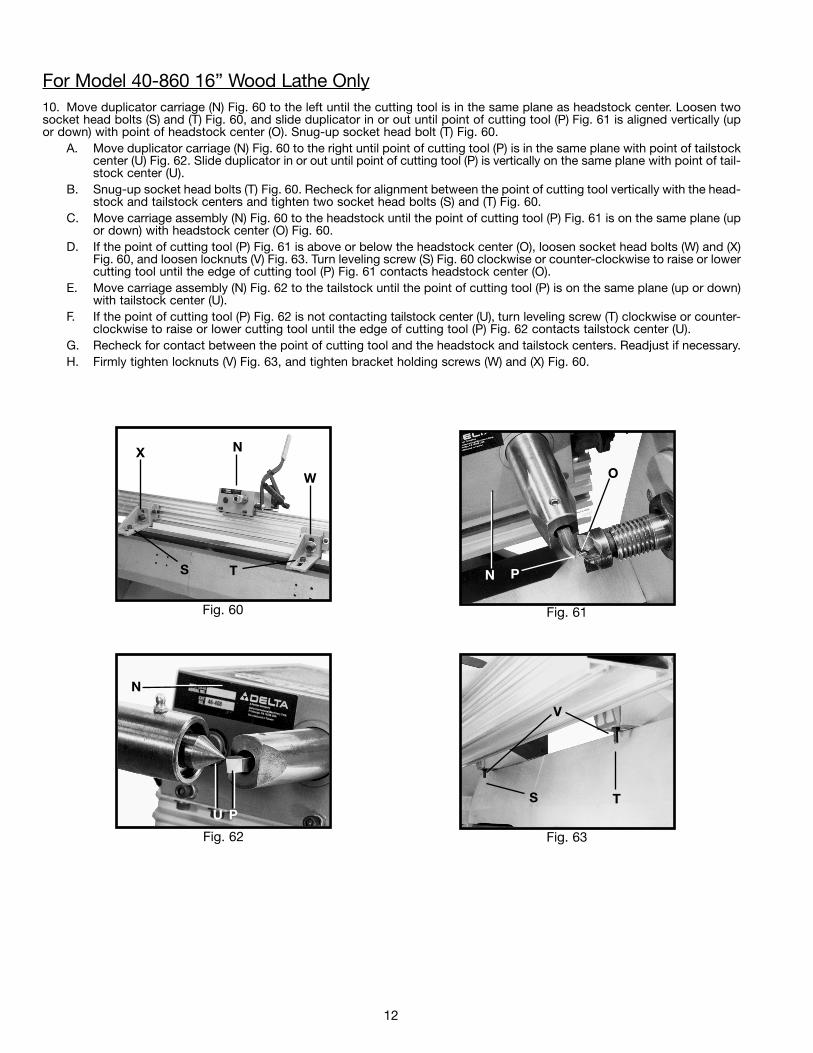
For Model 40-860 16” Wood Lathe Only10. Move duplicator carriage (N) Fig. 60 to the left until the cutting tool is in the same plane as headstock center. Loosen twosocket head bolts (S) and (T) Fig. 60, and slide duplicator in or out until point of cutting tool (P) Fig. 61 is aligned vertically (upor down) with point of headstock center (O). Snug-up socket head bolt (T) Fig. 60.
A. Move duplicator carriage (N) Fig. 60 to the right until point of cutting tool (P) is in the same plane with point of tailstockcenter (U) Fig. 62. Slide duplicator in or out until point of cutting tool (P) is vertically on the same plane with point of tail-stock center (U).
B. Snug-up socket head bolts (T) Fig. 60. Recheck for alignment between the point of cutting tool vertically with the head-stock and tailstock centers and tighten two socket head bolts (S) and (T) Fig. 60.
C. Move carriage assembly (N) Fig. 60 to the headstock until the point of cutting tool (P) Fig. 61 is on the same plane (upor down) with headstock center (O) Fig. 60.
D. If the point of cutting tool (P) Fig. 61 is above or below the headstock center (O), loosen socket head bolts (W) and (X)Fig. 60, and loosen locknuts (V) Fig. 63. Turn leveling screw (S) Fig. 60 clockwise or counter-clockwise to raise or lowercutting tool until the edge of cutting tool (P) Fig. 61 contacts headstock center (O).
E. Move carriage assembly (N) Fig. 62 to the tailstock until the point of cutting tool (P) is on the same plane (up or down)with tailstock center (U).
F. If the point of cutting tool (P) Fig. 62 is not contacting tailstock center (U), turn leveling screw (T) clockwise or counter-clockwise to raise or lower cutting tool until the edge of cutting tool (P) Fig. 62 contacts tailstock center (U).
G. Recheck for contact between the point of cutting tool and the headstock and tailstock centers. Readjust if necessary.H. Firmly tighten locknuts (V) Fig. 63, and tighten bracket holding screws (W) and (X) Fig. 60.
N P
O
N
U P
S
X N
W
T
V
TS
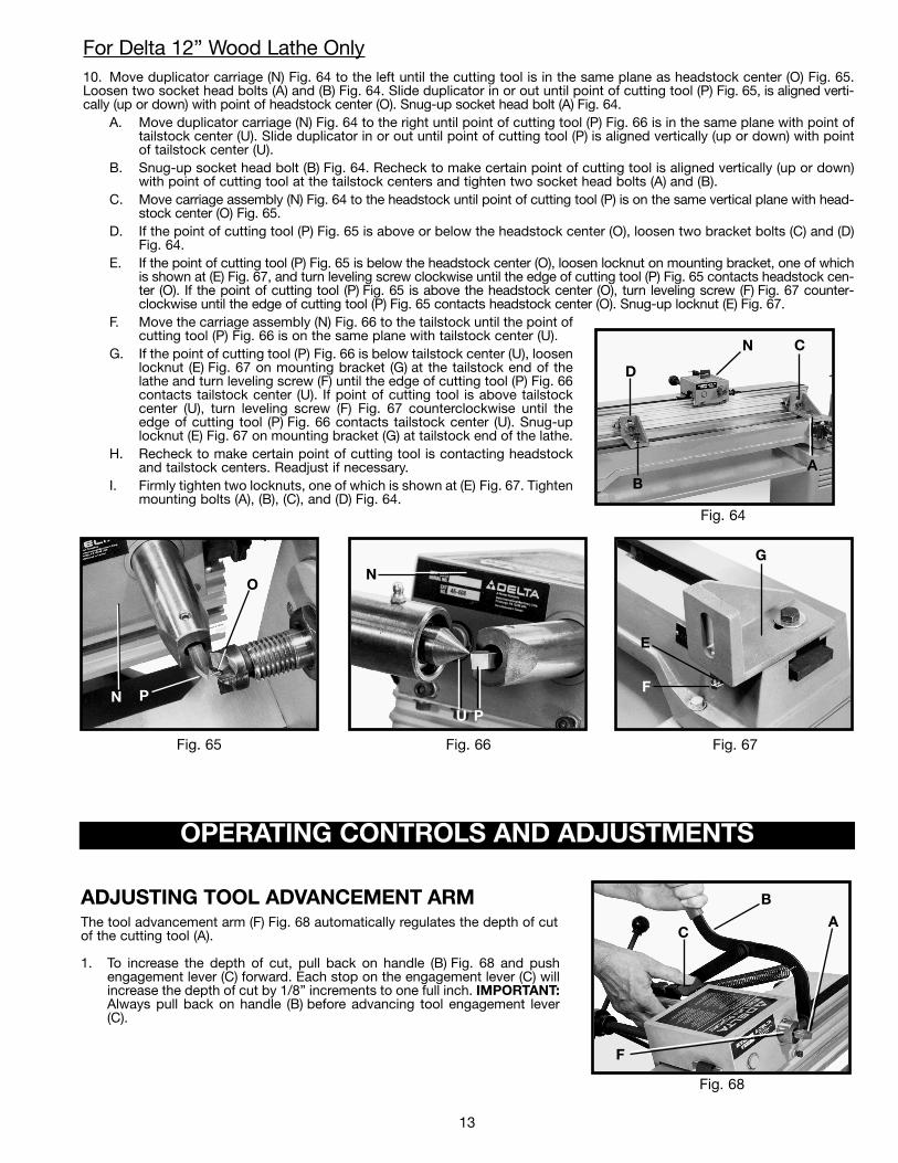
For Delta 12” Wood Lathe Only10. Move duplicator carriage (N) Fig. 64 to the left until the cutting tool is in the same plane as headstock center (O) Fig. 65.Loosen two socket head bolts (A) and (B) Fig. 64. Slide duplicator in or out until point of cutting tool (P) Fig. 65, is aligned verti-cally (up or down) with point of headstock center (O). Snug-up socket head bolt (A) Fig. 64.
A. Move duplicator carriage (N) Fig. 64 to the right until point of cutting tool (P) Fig. 66 is in the same plane with point oftailstock center (U). Slide duplicator in or out until point of cutting tool (P) is aligned vertically (up or down) with pointof tailstock center (U).
B. Snug-up socket head bolt (B) Fig. 64. Recheck to make certain point of cutting tool is aligned vertically (up or down)with point of cutting tool at the tailstock centers and tighten two socket head bolts (A) and (B).
C. Move carriage assembly (N) Fig. 64 to the headstock until point of cutting tool (P) is on the same vertical plane with head-stock center (O) Fig. 65.
D. If the point of cutting tool (P) Fig. 65 is above or below the headstock center (O), loosen two bracket bolts (C) and (D)Fig. 64.
E. If the point of cutting tool (P) Fig. 65 is below the headstock center (O), loosen locknut on mounting bracket, one of whichis shown at (E) Fig. 67, and turn leveling screw clockwise until the edge of cutting tool (P) Fig. 65 contacts headstock cen-ter (O). If the point of cutting tool (P) Fig. 65 is above the headstock center (O), turn leveling screw (F) Fig. 67 counter-clockwise until the edge of cutting tool (P) Fig. 65 contacts headstock center (O). Snug-up locknut (E) Fig. 67.
F. Move the carriage assembly (N) Fig. 66 to the tailstock until the point ofcutting tool (P) Fig. 66 is on the same plane with tailstock center (U).
G. If the point of cutting tool (P) Fig. 66 is below tailstock center (U), loosenlocknut (E) Fig. 67 on mounting bracket (G) at the tailstock end of thelathe and turn leveling screw (F) until the edge of cutting tool (P) Fig. 66contacts tailstock center (U). If point of cutting tool is above tailstockcenter (U), turn leveling screw (F) Fig. 67 counterclockwise until theedge of cutting tool (P) Fig. 66 contacts tailstock center (U). Snug-uplocknut (E) Fig. 67 on mounting bracket (G) at tailstock end of the lathe.
H. Recheck to make certain point of cutting tool is contacting headstockand tailstock centers. Readjust if necessary.
I. Firmly tighten two locknuts, one of which is shown at (E) Fig. 67. Tightenmounting bolts (A), (B), (C), and (D) Fig. 64.
13
Fig. 64
Fig. 65 Fig. 66 Fig. 67
OPERATING CONTROLS AND ADJUSTMENTS
Fig. 68
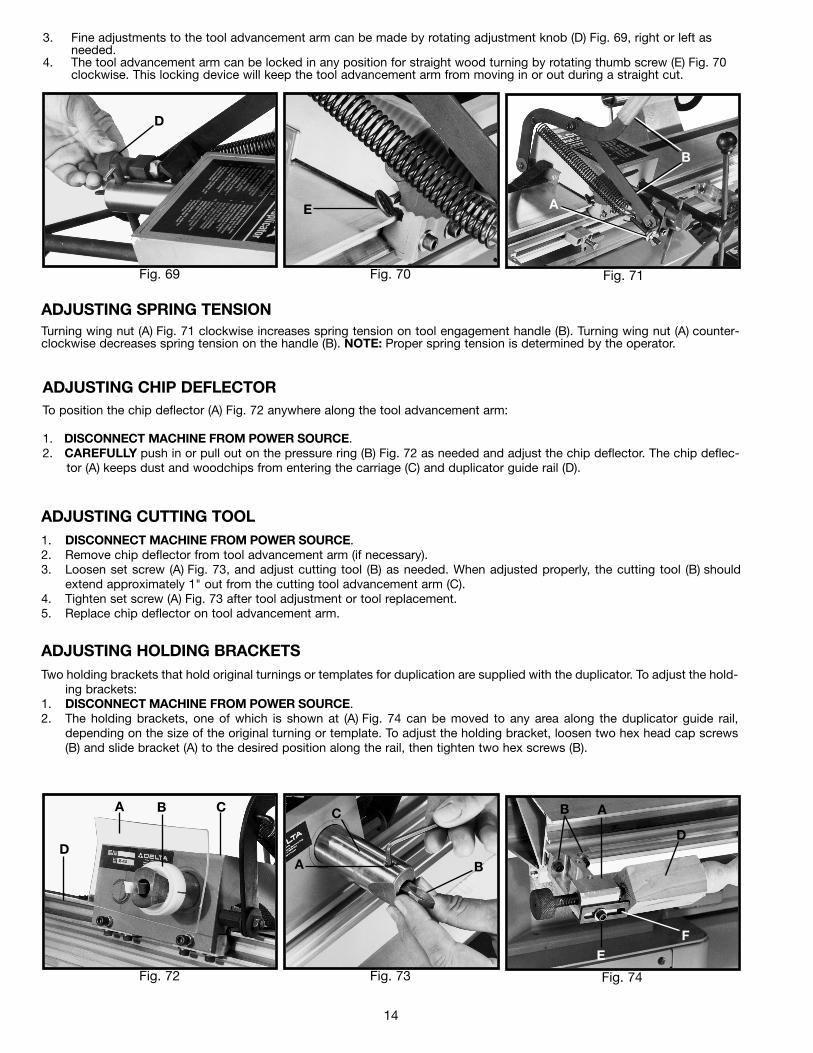
ADJUSTING TOOL ADVANCEMENT ARMThe tool advancement arm (F) Fig. 68 automatically regulates the depth of cutof the cutting tool (A).
1. To increase the depth of cut, pull back on handle (B) Fig. 68 and pushengagement lever (C) forward. Each stop on the engagement lever (C) willincrease the depth of cut by 1/8” increments to one full inch. IMPORTANT:Always pull back on handle (B) before advancing tool engagement lever(C).
D
B
C
A
C
B
A
N P
ON
U P
F
E
G
N
F
14
ADJUSTING CHIP DEFLECTORTo position the chip deflector (A) Fig. 72 anywhere along the tool advancement arm:
1. DISCONNECT MACHINE FROM POWER SOURCE.2. CAREFULLY push in or pull out on the pressure ring (B) Fig. 72 as needed and adjust the chip deflector. The chip deflec-
tor (A) keeps dust and woodchips from entering the carriage (C) and duplicator guide rail (D).
ADJUSTING CUTTING TOOL1. DISCONNECT MACHINE FROM POWER SOURCE.2. Remove chip deflector from tool advancement arm (if necessary).3. Loosen set screw (A) Fig. 73, and adjust cutting tool (B) as needed. When adjusted properly, the cutting tool (B) should
extend approximately 1" out from the cutting tool advancement arm (C).4. Tighten set screw (A) Fig. 73 after tool adjustment or tool replacement.5. Replace chip deflector on tool advancement arm.
ADJUSTING HOLDING BRACKETSTwo holding brackets that hold original turnings or templates for duplication are supplied with the duplicator. To adjust the hold-
ing brackets:1. DISCONNECT MACHINE FROM POWER SOURCE.2. The holding brackets, one of which is shown at (A) Fig. 74 can be moved to any area along the duplicator guide rail,
depending on the size of the original turning or template. To adjust the holding bracket, loosen two hex head cap screws(B) and slide bracket (A) to the desired position along the rail, then tighten two hex screws (B).
ADJUSTING SPRING TENSIONTurning wing nut (A) Fig. 71 clockwise increases spring tension on tool engagement handle (B). Turning wing nut (A) counter-clockwise decreases spring tension on the handle (B). NOTE: Proper spring tension is determined by the operator.
3. Fine adjustments to the tool advancement arm can be made by rotating adjustment knob (D) Fig. 69, right or left as needed.
4. The tool advancement arm can be locked in any position for straight wood turning by rotating thumb screw (E) Fig. 70clockwise. This locking device will keep the tool advancement arm from moving in or out during a straight cut.
Fig. 69 Fig. 70 Fig. 71
Fig. 72 Fig. 73 Fig. 74
D
E
B
A
D
A B C C
A B
B A
D
FE
15
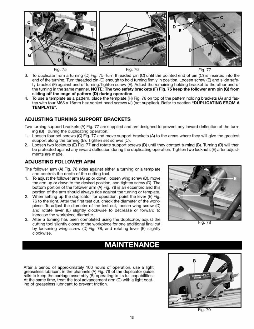
3. To duplicate from a turning (D) Fig. 75, turn threaded pin (C) until the pointed end of pin (C) is inserted into theend of the turning. Turn threaded pin (C) enough to hold turning firmly in position. Loosen screw (E) and slide safe-ty bracket (F) against end of turning.Tighten screw (E). Adjust the remaining holding bracket to the other end ofthe turning in the same manner. NOTE: The two safety brackets (F) Fig. 75 keep the follower arm pin (G) fromsliding off the edge of pattern (D) during operation.
4. To use a template as a pattern, place the template (H) Fig. 76 on top of the pattern holding brackets (A) and fas-ten with four M65 x 16mm hex socket head screws (J) (not supplied). Refer to section “DUPLICATING FROM ATEMPLATE”.
ADJUSTING TURNING SUPPORT BRACKETSTwo turning support brackets (A) Fig. 77 are supplied and are designed to prevent any inward deflection of the turn-
ing (B) during the duplicating operation.1. Loosen four set screws (C) Fig. 77 and move support brackets (A) to the areas where they will give the greatest
support along the turning (B). Tighten set screws (C).2. Loosen two locknuts (E) Fig. 77 and rotate support screws (D) until they contact turning (B). Turning (B) will then
be protected against any inward deflection during the duplicating operation. Tighten two locknuts (E) after adjust-ments are made.
ADJUSTING FOLLOWER ARMThe follower arm (A) Fig. 78 rides against either a turning or a template
and controls the depth of the cutting tool. 1. To adjust the follower arm (A) up or down, loosen wing screw (D), move
the arm up or down to the desired position, and tighten screw (D). Thebottom portion of the follower arm (A) Fig. 78 is an eccentric and thisportion of the arm should always ride against the turning or template.
2. When setting up the duplicator for operation, point the lever (E) Fig.76 to the right. After the first test cut, check the diameter of the work-piece. To adjust the diameter of the test cut, loosen wing screw (D)and rotate lever (E) slightly clockwise to decrease or forward toincrease the workpiece diameter.
3. After a turning has been completed using the duplicator, adjust thecutting tool slightly closer to the workpiece for one additional final cutby loosening wing screw (D) Fig. 78, and rotating lever (E) slightlyclockwise.
Fig. 78
Fig. 75 Fig. 76 Fig. 77
MAINTENANCE
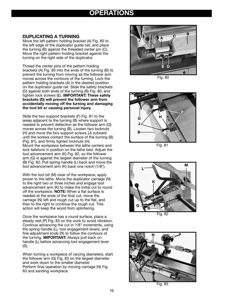
After a period of approximately 100 hours of operation, use a lightgreaseless lubricant in the channels (A) Fig. 79 of the duplicator guiderails to keep the carriage assembly (B) operating to its full capabilities.At the same time, treat the tool advancement arm (C) with a light coat-ing of greaseless lubricant to prevent friction.
Fig. 79
F
DG
F
J
H
A
DE A
C
BC
DE
A
A
D
E
A
B
C
C
E
16
OPERATIONS
DUPLICATING A TURNINGMove the left pattern holding bracket (A) Fig. 80 tothe left edge of the duplicator guide rail, and placethe turning (B) against the threaded center pin (C).Move the right pattern holding bracket against theturning on the right side of the duplicator.
Thread the center pins of the pattern holding brackets (A) Fig. 80 into the ends of the turning (B) toprevent the turning from moving as the follower armmoves across the contours of the turning. Lock thepattern holding brackets (A) in the desired positionon the duplicator guide rail. Slide the safety brackets(D) against both ends of the turning (B) Fig. 80, andtighten lock screws (E). IMPORTANT: These safetybrackets (D) will prevent the follower arm fromaccidentally moving off the turning and damagingthe tool bit or causing personal injury.
Slide the two support brackets (F) Fig. 81 to theareas adjacent to the turning (B) where support isneeded to prevent deflection as the follower arm (G)moves across the turning (B). Loosen two locknuts(H) and move the two support screws (J) outwarduntil the screws contact the surface of the turning (B)(Fig. 81), and firmly tighten locknuts (H).Mount the workpiece between the lathe centers andlock tailstock in position on the lathe bed. Adjust thetool advancement arm (K) Fig. 82, so the followerarm (G) is against the largest diameter of the turning(B) Fig. 82. Pull spring handle (L) back and move thetool advancement arm (K) back one notch (1/8").
With the tool bit (M) clear of the workpiece, applypower to the lathe. Move the duplicator carriage (N)to the right two or three inches and engage tooladvancement arm (K) to make the initial cut to roundoff the workpiece. NOTE: When a flat surface isneeded at the ends of the final cut, move thecarriage (N) left and rough cut up to the flat, andthen to the right to continue the rough cut. Thisaction will keep the wood from splintering.
Once the workpiece has a round surface, place asteady rest (P) Fig. 83 on the work to avoid vibration.Continue advancing the cut in 1/8" increments, usingthe spring handle (L), tool engagement levers, andfine adjustment knob (R) to follow the contours ofthe turning. IMPORTANT: Always pull back on handle (L) before advancing tool engagement lever(S).
When turning a workpiece of varying diameters, startthe follower arm (G) Fig. 83 on the largest diameterand work down to the smaller diameter.Perform final operation by moving carriage (N) Fig.83 and sanding workpiece.
Fig. 80
Fig. 81
Fig. 82
Fig. 83
PNL
S
R
G
L
K
GB N
M
FH
B
JG
E D
A CB
1717
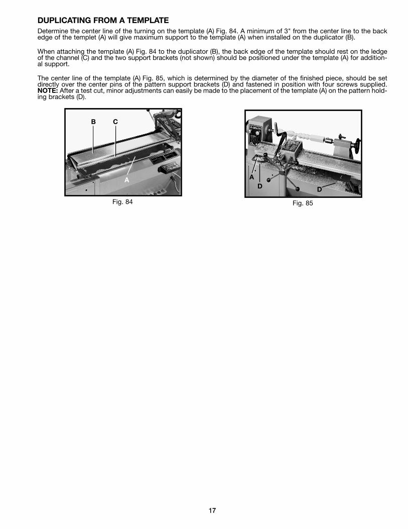
DUPLICATING FROM A TEMPLATEDetermine the center line of the turning on the template (A) Fig. 84. A minimum of 3" from the center line to the backedge of the templet (A) will give maximum support to the template (A) when installed on the duplicator (B).
When attaching the template (A) Fig. 84 to the duplicator (B), the back edge of the template should rest on the ledgeof the channel (C) and the two support brackets (not shown) should be positioned under the template (A) for addition-al support.
The center line of the template (A) Fig. 85, which is determined by the diameter of the finished piece, should be setdirectly over the center pins of the pattern support brackets (D) and fastened in position with four screws supplied.NOTE: After a test cut, minor adjustments can easily be made to the placement of the template (A) on the pattern hold-ing brackets (D).
Fig. 84 Fig. 85
A
CB
AD D

NOTES
1818

19
Two Year Limited WarrantyDelta will repair or replace, at its expense and at its option, any Delta machine, machine part, or machine accessory whichin normal use has proven to be defective in workmanship or material, provided that the customer returns the product pre-paid to a Delta factory service center or authorized service station with proof of purchase of the product within two yearsand provides Delta with reasonable opportunity to verify the alleged defect by inspection. Delta may require that electricmotors be returned prepaid to a motor manufacturer’s authorized station for inspection and repair or replacement. Deltawill not be responsible for any asserted defect which has resulted from normal wear, misuse, abuse or repair or alterationmade or specifically authorized by anyone other than an authorized Delta service facility or representative. Under no cir-cumstances will Delta be liable for incidental or consequential damages resulting from defective products. This warrantyis Delta’s sole warranty and sets forth the customer’s exclusive remedy, with respect to defective products; all other war-ranties, express or implied, whether of merchantability, fitness for purpose, or otherwise, are expressly disclaimed by Delta.
PARTS, SERVICE OR WARRANTY ASSISTANCEAll Delta Machines and accessories are manufactured to high quality standards and are serviced by a networkof Porter-Cable • Delta Factory Service Centers and Delta Authorized Service Stations. To obtain additionalinformation regarding your Delta quality product or to obtain parts, service, warranty assistance, or the loca-tion of the nearest service outlet, please call 1-800-223-7278 (In Canada call 1-800-463-3582).

The following are trademarks of PORTER-CABLE • DELTA (Las siguientes son marcas registradas de PORTER-CABLE • DELTA S.A.) (Les marquessuivantes sont des marques de fabriquant de la PORTER-CABLE • DELTA): Auto-Set®, BAMMER®, B.O.S.S.®, Builder’s Saw®, Contractor’s Saw®,Contractor’s Saw II™, Delta®, DELTACRAFT®, DELTAGRAM™, Delta Series 2000™, DURATRONIC™, Emc²™, FLEX®, Flying Chips™, FRAME SAW®,Grip Vac™, Homecraft®, INNOVATION THAT WORKS®, Jet-Lock®, JETSTREAM®, ‘kickstand®, LASERLOC®, MICRO-SET®, Micro-Set®, MIDI LATHE®,MORTEN™, NETWORK™, OMNIJIG®, POCKET CUTTER®, PORTA-BAND®, PORTA-PLANE®, PORTER-CABLE®&(design), PORTER-CABLE®PROFES-SIONAL POWER TOOLS, PORTER-CABLE REDEFINING PERFORMANCE™, Posi-Matic®, Q-3®&(design), QUICKSAND®&(design), QUICKSET™,QUICKSET II®, QUICKSET PLUS™, RIPTIDE™&(design), SAFE GUARD II®, SAFE-LOC®, Sanding Center®, SANDTRAP®&(design), SAW BOSS®,Sawbuck™, Sidekick®, SPEED-BLOC®, SPEEDMATIC®, SPEEDTRONIC®, STAIR EASE®, The American Woodshop®&(design), The LumberCompany®&(design), THE PROFESSIONAL EDGE®, THE PROFESSIONAL SELECT®, THIN-LINE™, TIGER®, TIGER CUB®, TIGER SAW®, TORQ-BUSTER®, TORQ-BUSTER®, TRU-MATCH™, TWIN-LITE®, UNIGUARD®, Unifence®, UNIFEEDER™, Unihead®, Uniplane™, Unirip®, Unisaw®, Univise®,Versa-Feeder®, VERSA-PLANE® , WHISPER SERIES®, WOODWORKER’S CHOICE™. Trademarks noted with ™ and ® are registered in the United States Patent and Trademark Office and may also be registered in other countries. LasMarcas Registradas con el signo de ™ y ® son registradas por la Oficina de Registros y Patentes de los Estados Unidos y también pueden estarregistradas en otros países.
PORTER-CABLE • DELTA SERVICE CENTERS(CENTROS DE SERVICIO DE PORTER-CABLE • DELTA)
Parts and Repair Service for Porter-Cable • Delta Machinery are Available at These Locations(Obtenga Refaccion de Partes o Servicio para su Herramienta en los Siguientes Centros de Porter-Cable • Delta)
Authorized Service Stations are located in many large cities. Telephone 800-438-2486 or 731-541-6042 for assistance locating one.Parts and accessories for Porter-Cable·Delta products should be obtained by contacting any Porter-Cable·Delta Distributor, AuthorizedService Center, or Porter-Cable·Delta Factory Service Center. If you do not have access to any of these, call 800-223-7278 and you willbe directed to the nearest Porter-Cable·Delta Factory Service Center. Las Estaciones de Servicio Autorizadas están ubicadas en muchasgrandes ciudades. Llame al 800-438-2486 ó al 731-541-6042 para obtener asistencia a fin de localizar una. Las piezas y los accesoriospara los productos Porter-Cable·Delta deben obtenerse poniéndose en contacto con cualquier distribuidor Porter-Cable·Delta, Centrode Servicio Autorizado o Centro de Servicio de Fábrica Porter-Cable·Delta. Si no tiene acceso a ninguna de estas opciones, llame al800-223-7278 y le dirigirán al Centro de Servicio de Fábrica Porter-Cable·Delta más cercano.
ARIZONATempe 85282 (Phoenix)2400 West Southern AvenueSuite 105Phone: (602) 437-1200Fax: (602) 437-2200
CALIFORNIAOntario 91761 (Los Angeles)3949A East Guasti RoadPhone: (909) 390-5555Fax: (909) 390-5554
San Diego 921117638 Clairemnot Blvd.Phone: (858) 277-9595Fax: (858) 277-9696
San Leandro 94577 (Oakland)3039 Teagarden StreetPhone: (510) 357-9762Fax: (510) 357-7939
COLORADOArvada 80003 (Denver)8175 Sheridan Blvd., Unit SPhone: (303) 487-1809Fax: (303) 487-1868
FLORIDADavie 33314 (Miami)4343 South State Rd. 7 (441)Unit #107Phone: (954) 321-6635Fax: (954) 321-6638
Tampa 33609 4538 W. Kennedy BoulevardPhone: (813) 877-9585Fax: (813) 289-7948
GEORGIAForest Park 30297 (Atlanta)5442 Frontage Road,Suite 112Phone: (404) 608-0006Fax: (404) 608-1123
ILLINOISAddison 60101 (Chicago)400 South Rohlwing Rd.Phone: (630) 424-8805Fax: (630) 424-8895
Woodridge 60517 (Chicago)2033 West 75th StreetPhone: (630) 910-9200Fax: (630) 910-0360
MARYLANDElkridge 21075 (Baltimore)7397-102 Washington Blvd.Phone: (410) 799-9394Fax: (410) 799-9398
MASSACHUSETTSFranklin 02038 (Boston)Franklin Industrial Park101E Constitution Blvd.Phone: (508) 520-8802Fax: (508) 528-8089
MICHIGANMadison Heights 48071 (Detroit)30475 Stephenson HighwayPhone: (248) 597-5000Fax: (248) 597-5004MINNESOTAMinneapolis 554295522 Lakeland Avenue NorthPhone: (763) 561-9080Fax: (763) 561-0653
MISSOURINorth Kansas City 641161141 Swift AvenuePhone: (816) 221-2070Fax: (816) 221-2897
St. Louis 631197574 Watson RoadPhone: (314) 968-8950Fax: (314) 968-2790
NEW YORKFlushing 11365-1595 (N.Y.C.)175-25 Horace Harding Expwy.Phone: (718) 225-2040Fax: (718) 423-9619
NORTH CAROLINACharlotte 282709129 Monroe Road, Suite 115Phone: (704) 841-1176Fax: (704) 708-4625
OHIOColumbus 432144560 Indianola AvenuePhone: (614) 263-0929Fax: (614) 263-1238
Cleveland 441258001 Sweet Valley DriveUnit #19Phone: (216) 447-9030Fax: (216) 447-3097
OREGONPortland 972304916 NE 122 nd Ave.Phone: (503) 252-0107Fax: (503) 252-2123
PENNSYLVANIAWillow Grove 19090(Philadelphia)520 North York RoadPhone: (215) 658-1430Fax: (215) 658-1433
TEXASCarrollton 75006 (Dallas)1300 Interstate 35 N, Suite 112Phone: (972) 446-2996Fax: (972) 446-8157
Houston 770434321 Sam Houston Parkway,WestSuite 180Phone: (713) 983-9910Fax: (713) 983-6645
WASHINGTONAuburn 98001(Seattle)3320 West Valley HWY, NorthBuilding D, Suite 111Phone: (253) 333-8353Fax: (253) 333-9613
Printed in U.S.A. PC-0104-149
CANADIAN PORTER-CABLE • DELTA SERVICE CENTERSALBERTABay 6, 2520-23rd St. N.E.Calgary, AlbertaT2E 8L2Phone: (403) 735-6166Fax: (403) 735-6144
BRITISH COLUMBIA8520 Baxter PlaceBurnaby, B.C.V5A 4T8Phone: (604) 420-0102Fax: (604) 420-3522
MANITOBA1699 Dublin AvenueWinnipeg, ManitobaR3H 0H2Phone: (204) 633-9259Fax: (204) 632-1976
ONTARIO505 Southgate DriveGuelph, OntarioN1H 6M7Phone: (519) 767-4132Fax: (519) 767-4131
QUÉBEC1515 ave.St-Jean Baptiste, Suite 160Québec, QuébecG2E 5E2Phone: (418) 877-7112Fax: (418) 877-7123
1447, BeginSt-Laurent, (Montréal),QuébecH4R 1V8Phone: (514) 336-8772Fax: (514) 336-3505