woodworking plans making the cut level 2 science/level2_woodworking...woodworking plans making the...
TRANSCRIPT
Woodworking Plans Making the Cut
Level 2
Purdue University, Indiana Counties and U.S. Department of Agriculture Cooperating
An Affirmative Action/Equal Opportunity Institution

.,
CUTTING BOARD
The wood used to form the cutting board is cut into pairs. Thus you start with one center piece for the handle and glue each matching pair on both sides of the center piece. This results in a symmetrical pattern that balances the cutting board visually.
Materials Needed: (Finished dimensions in inches)
A Slat B Slat C Slat D Slat
3/4 x 3/4 x 9 hardwood 4 1/2 x 3/4 x 9 hardwood 4 1/4 x 3/4 x 9 hardwood 6 3/4 x 2 x 13 1/4 hardwood 1
Use the faced wood surface as the area to edge-glue. This forms a straight glue joint. Cut the strips to 3/4 inch width (cutting board thickness). Place the strips on edge and glue. If you cut the strips to correct cutting board thickness, these surfaces will be difficult to finish because they are so small.
Make an overall cutting board pattern out of paper or cardboard and lay and arrange the cut strips onto the pattern. When the arrangement suits you, prepare the workpieces for gluing.
Place wax paper on a flat surface where you are to glue the cutting board. Carefully keep all workpieces in their correct order. Then brush on a thin coat of carpenter's glue to one mating surface. Join and rub each workpiece firmly as you proceed through the gluing process. Secure the assembly with bar clamps and with one cross beam placed across the assembly's middle. Place wax paper under the cross beam. Clamp this beam to prevent the strips from sliding up as you apply side clamping pressure. Do not apply too much clamping pressure. Make sure the strips sit flat on the work surface. Then allow the assembly to dry for 24 hours.
Once the glue has cured remove the glue that has squeezed up with an old wood chisel. This makes it easier to finish the wood surfaces. Use a belt sander to finish the board's surfaces. Then transfer the pattern's design to the assembly. Drill the two radii at the handle's base with a Forstner bit, positioned in a drill press or drill guide.
Next, cut the board's perimeter with a band saw, using a 1/4 in. or 3/8 in. blade. Carefully round the comer radii and sand all edges with an abrasive sander. Finally, with a rasp and power sander, round the edges.
Fine sand the cutting board and apply several coats of vegetable oil or some of the cutting board oils available at fine cutlery shops.
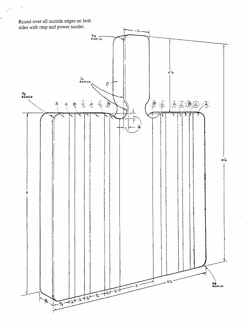
Round over all outside edges on both sides with rasp and power sander.
C A . .--

ADJUSTABLE BOOK RACK
Materials Needed: (finished dimensions in inches)
A B c D
Large end Small end Adjustable end Dowels (5)
Instructions:
3/4 x 5-1/2 x 7 3/4 x 5-1/2 x 3 3/4 x 5-1/2 x 6-1/2 1/2 dia. x 18
1. Cut all the stock to size according to the list of materials. 2. Drill the 1/2" diameter x 1/2" deep holes in the ends (A, B). 3. Using a T-bevel and drill, drill the 9/16" through-holes in the adjustable end at a 5° angle. 4. Round over the edges using a rasp and sandpaper. 5. Sand all the parts. Do not sand the ends of the dowels (D). 6. Assemble with glue and clamp securely. Be careful not to get any glue on part (C). 7. Apply the finish of your choice.
9/16" DIA. HOLE AT 5° TILT (5 REQUIRED}
1/2" DIA. x 1/2" DEEP HOLE ,
9/16" OIA. HOLE DRILLED AT 5°
(5 gzR:O_,_) __ f'L"1-___ __..,..,
From HANDS ON Nov/Dec 84

TAPE & PAPER CLIP DISPENSER
Materials Needed:
• 1 x 4 x 6" Actual thickness of lumber is about 3/4" .) • 3/8" x 3 1/2" x 12" (actual dimensions for the two outside pieces) • 3/4" dowel, as long as the dispenser is wide • Glue • 1 " wire brads • Finishing materials
Tools Needed:
• Trace pattern materials • Coping saw (or jig saw) • Hammer • Drill and 3/4" bit • Nail set
Instructions:
1. Match the outlines of the plastic tape dispenser to the lines on the drawing. Adjust so the dispenser will slip in the hole cut out of the center piece.
2. Transfer the trace pattern to the 3 pieces of wood. 3. Cut out the 3 pieces. The center piece is shorter and has the paper clip storage hole cut out
of it. 4. Hold the 3 pieces together and check that the plastic tape dispenser will slide in. If it is tight,
partly sand off the plastic hub retainer knobs. 5. Drill the 3/4" hole. 6. Sand the inside curve and storage hole of the center piece. 7. Glue together. Then sand edges.
HOLE CUT OUT FROM
··:·?/::((//:-. CENTER PIECE FOR \{§)}{}:::.:.... PAPER CLIP STORAGE
TRACE PATTERN CENTER PIECE

STORAGE FOR GROCERY BAGS
Materials Needed:
• 1-1/2 inch by 12 inches by 32 inches piece of hardboard • 1-3/8 inch by 1 1/4 inches by 48 inches piece of plywood • Finish materials you select
Instructions:
• Glue pieces together.
/
/ /
/
ix stx 9t Hardboard
/
/ /
/
/ /
/
/ /
l. x 9 x 12 8 Hardboard
/ /,, / 4
f X It Plywood
lsomet-ic View
1ot

STEPLADDER PLANT STAND
Materials Needed: (finished dimensions in inches)
A B c D
Base pieces (2) Legs (4) Braces (2) Shelves (3) 10 d galvanized nails Water-resistant wood glue
1-1/2 x 3-1/2 x 22 1-1/2 x 3-1/2 x 20 1-1/2x 3-1/2 x7-l/2 3/4 x 7-1/4 x 30
Instructions:
1. Cut all the pieces to size according to the dimensions given. 2. Cut a 22° bevel on each end of each leg (B) so that, when installed, the legs will slant in but
their ends will remain parallel. 3. Measure from the outside edge 2" across the beveled end at the top of each leg and square a
line down from that point. Cut along those lines to create the joints between legs shown in the drawing.
4. Place a pair of legs together on a flat surface and lay a brace (C) across their upper ends. Adjust the brace so that its upper edge is parallel to and 3/4" below the upper ends of the legs. Mark and trim the ends of the brace so they will be flush with the outside edges of the legs. Repeat with the other brace and pair of legs.
5. Begin the assembly of the stand by laying each pair of legs across its brace and base piece (A). Make sure the bottom edges of the legs and base are flush and that the base extends an equal distance to either side. Fasten the legs to the base and brace using water-resistant wood glue and 1 Od galvanized nails. If working with redwood, blunt the ends of the nails before using.
6. Set the two leg units upright and fit the shelves (D) between them. Make sure the outer edge of each lower shelf is flush with the ends of the base and that the upper shelf is centered over the braces. Fasten the shelves in place using waterresistant wood glue and 1 Od galva-nized nails. c
7. Blunt any penetrating nail ends and break over all sharp edges. Apply a water-resistant finish.
7 1
/2"

MITER BOX
Materials Needed:
• 2-1 inch by 6 inches by 24 inches (Make sure to use a hardwood for the side pieces.) • 1-2 inches by 6 inches by 24 inches (Softwood is okay for the base.) • 8-Number 8 flathead screws
Top View
Drill & countersink for no. 8 screw
i--"--4·--~
..,_. ___ 7·---~ i...¥.1----- 51---~Mil
~-T-T-.1 1,.......-+--r-
st

BOOK HOLDER
Materials Needed:
• 1-1 inch by 6 inches by 32 inches piece • 4-Number 3 by 1 inch flathead wood screw • 1-5 5/8 inches by 16 inches felt • Finish materials you select
Tools Needed:
• Saw • Wood chisel (See note below.)
NOTES: • Felt glued to underside of bookholder. • A saw and wood chisel may be used to cut the grooves in the base piece where the
sides sit.
Instructions:
1. Cut material to proper size. 2. Assemble. 3. Glue all joints and felt to bottom.
Top View
~l----~~~~~~-1s~~~~~~~~--~
T Side View
I. I
Si I I t
-i t
1
3 _,____
4
End View
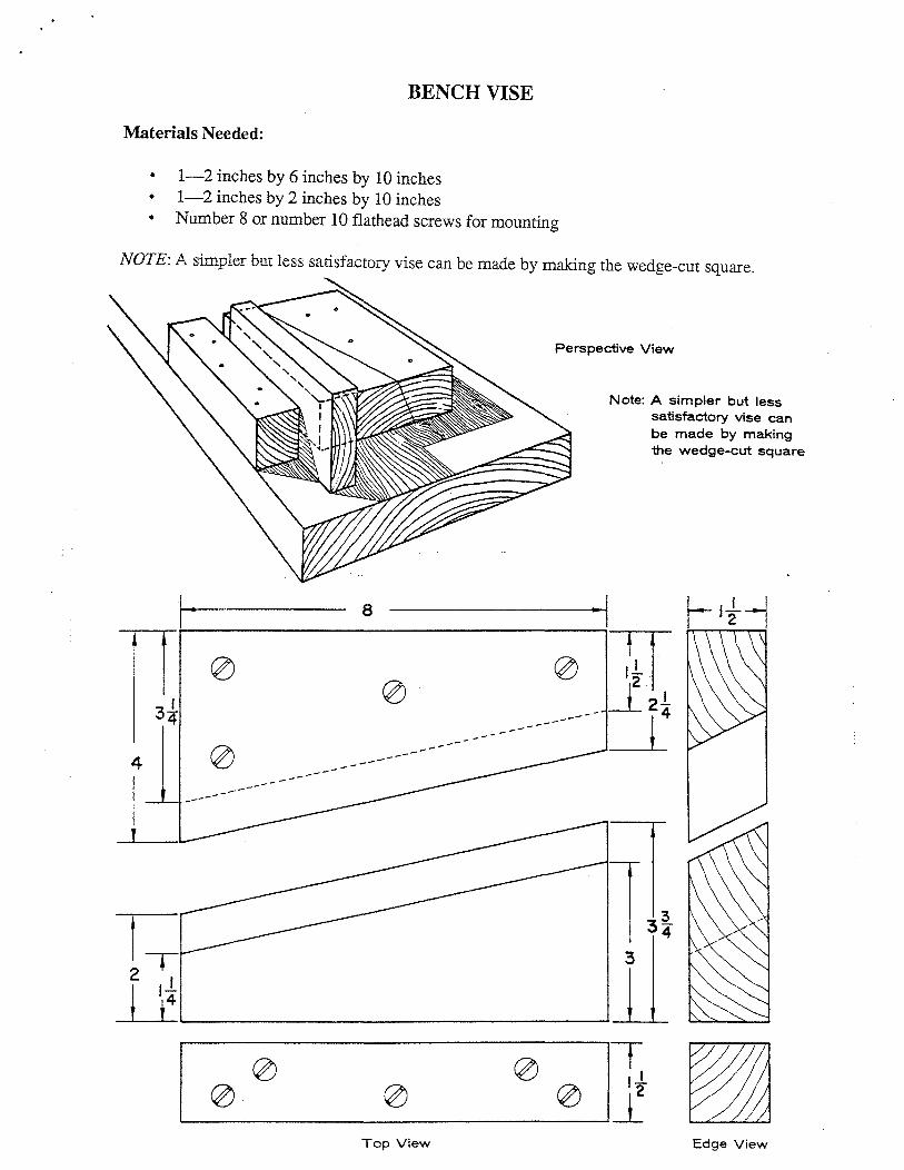
BENCH VISE
Materials Needed:
• 1-2 inches by 6 inches by 10 inches • 1-2 inches by 2 inches by 10 inches • Number 8 or number 10 flathead screws for mounting
NOTE: A simpler but less satisfactory vise can be made by making the wedge-cut square.
8
-----
I.
--
Perspective View
---
Note: A simpler but less satisfactory vise can be made by making the wedge-cut square
2
~L-~~~~~~~~~~~~~~~~~--
Top View Edge View

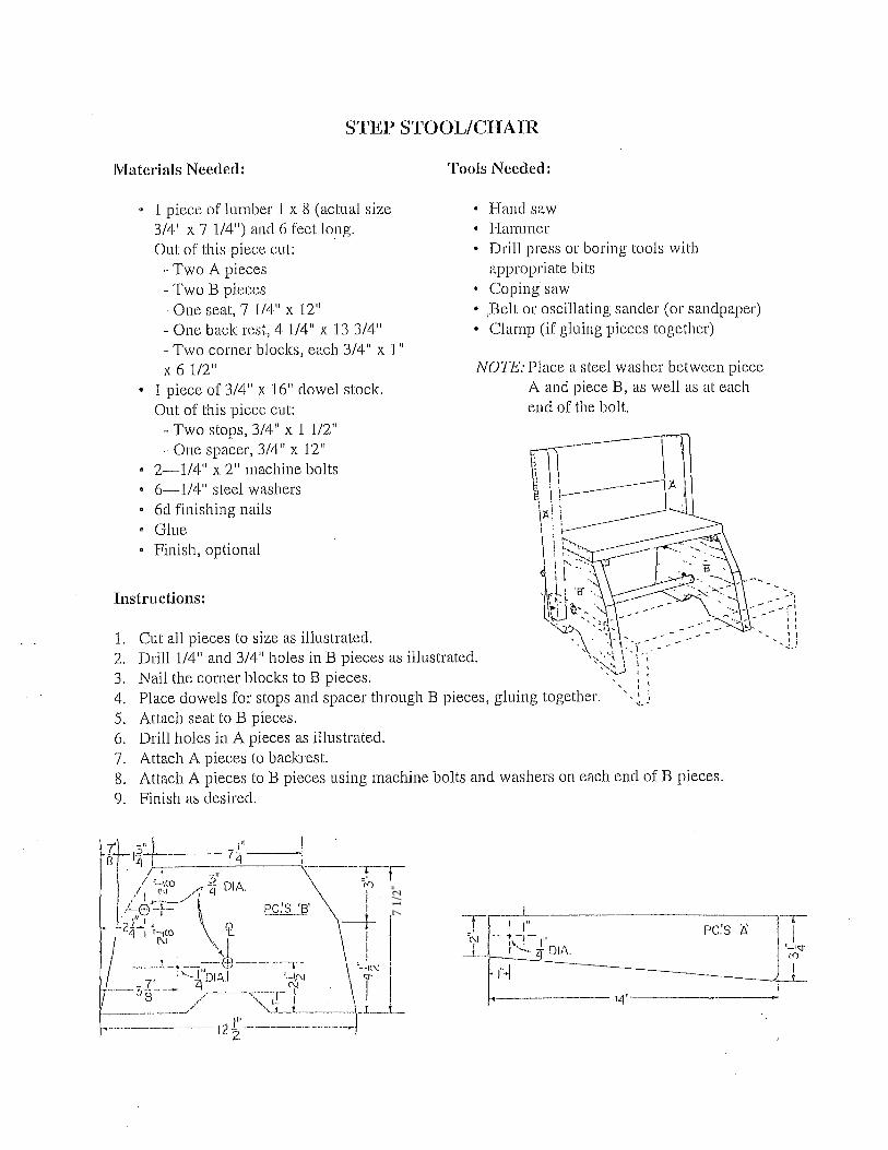
FOOTSTOOL
Materials Needed:
• 2-1 inch by 3 inches by 14 1/2 inches • 2-1 inch by 10 inches by 8 inches • 1-1 inch by 10 inches by 16 inches • 8-Number 10 by 1 1/2 inches round head wood screws • 4-Number 10 by 1 1/4 inches round head wood screws • Finish materials you select
Instructions:
1. Cut material to proper size. 2. Assemble ends and sides
and then attach top.
Side Piece
I 2
--...... ___ ..,,.,...
t __ _,
+F2~1
I 2
it 0 X It Deep
Isometric View
End Piece
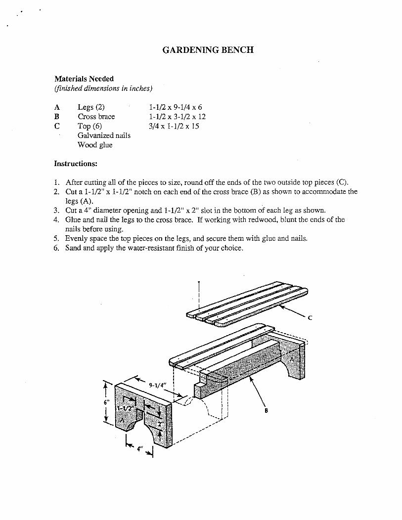
GARDENING BENCH
Materials Needed (finished dimensions in inches)
A B c
Legs (2) Cross brace Top (6) Galvanized nails Wood glue
Instructions:
1-1/2 x 9-1/4 x 6 1-1/2 x 3-1/2 x 12 3/4x 1-1/2x 15
1. After cutting all of the pieces to size, round off the ends of the two outside top pieces (C). 2. Cut a 1-1/2" x 1-1/2" notch on each end of the cross brace (B) as shown to accommodate the
legs (A). 3. Cut a 4" diameter opening and 1-1/2" x 2" slot in the bottom of each leg as shown. 4. Glue and nail the legs to the cross brace. If working with redwood, blunt the ends of the
nails before using. 5. Evenly space the top pieces on the legs, and secure them with glue and nails. 6. Sand and apply the water-resistant finish of your choice.
f 6"
l, B

SAWHORSE
Materials Needed: (for horse with 24" legs)
• 1piece2 x 4 lumber (actual size 1 1/2" x 3 1/2") 12 feet long, sound wood, free from cross grain, shakes or other defects which will reduce the strength
• 1 piece 1 x 6 lumber (actual size 3/4" x 5 1/2") 2 feet long
• 8-No. 14, 3" flathead wood screws • 20--No. 12, 2" flathead wood screws • 20--4d finishing nails • Colorless penetrating wood finish, such
as boiled linseed oil or varnish with paint thinner or commercial wood weal
Instructions:
1. Lay out and cut all pieces. 2. Assemble saw horse as shown with nails. 3. Drill pilot holes and install screws.
Tools Needed: • Hammer • Crosscut saw • Screwdriver • Countersink • Combination square • Sandpaper • Tape rule • T bevel
4. After the legs are marked and cut out, 1 1/2" is cut off the tapered end to give a narrow, flat end section. The flat end section will be flush with the top of the beam.
WOOD SCREWS WOOD SCREWS
SIDE VIEW f ..
Suggested Construction Dimensions:
Horse height Leg distance (top from beam end
18" 3 1/8" 20" 3 1/2" 24" 4 1/4"
,,4h
~·___J 13 16 I
END VIEW
Layout leg Trimmed length leg length
20 5/8" 19 3/8" 22 5/8" 21 3/8' 26 3/4" 25 1/2"

'· ..
Materials Needed: (finished dimensions in inches)
A B c D E F G
Column sides (4) Base piece Base piece Feet (4) Top Bracket Apron pieces ( 4) Flathead wood screws Wood plugs Wood glue
Instructions:
PLANT STAND
3/4x4x29 3/4 x 7-1/2 x 7-1/2 3/4 x 9-1/2 x 9-1/2 3/4 x 3 x 3 3/4 x 11-1/2 x 11-1/2 3/4 x 7 x 7 3/4 x 3/4 x 10-1/2 #6 x 1-1/4 3/8 dia.
1. Cut all of the pices to size according to the dimensions given.
2. Cut three plug holes in each column side (A) as shown. Locate the holes 2-1/2" from each end, with the remaining hole in between. All of the holes should be centered 3/8" from one edge of the piece.
3. Drill pilot holes for the wood screws in the center of the plug holes.
4. Assemble the column by gluing and screwing one corner at a time. Be sure that the assembly is square.
5. Round the edges of the column by sanding. 6. Make 90" butt joints at the corners of the apron pieces
(G). 7. Round the upper edges of the top (E), then center the
apron pieces on the underside of the top. Glue and screw through the apron into the top.
8. Center the bracket (F) on the column; then glue and screw it in place. Center the top/apron assembly on the bracket; glue and screw through the bracket into the apron.
9. Round the upper edges of the base pieces (B, C) and feet (D); then sand.
10. Center the small base piece on the bottom of the column. Glue and screw it in place from underneath. Repeat with the large base piece.
11. Position the feet so they extend beyond the corners of the base as shown; secure with glue and screws.
12. Sand the completed plant stand; finish as desired.
... ,,. ·.· .. ·.··•··.·····
=+ 2-1/2"
1 14-1/2"
l
FOOT DETAIL