worcester chlorine ball valves - flowserve corporation 441.pdf · worcester chlorine ball valves...
TRANSCRIPT

Worcester Chlorine Ball ValvesCorrosion resistant valves for critical chlorine applications
Worcester Controls SB 441-19
An ISO 9001 Registered Company

2 SB 441-19
Flow Control Division
Worcester Controls
Worcester Controls has the quality solution for tough applicationsinvolving chlorine, from the manufacture of the basic chemical toprocesses involving its use including pulp and paper bleaching andproduction of feedstocks.
With many years experience in handling dry chlorine (less than 150ppm water), Worcester offers two basic lines of valves; the SeriesCL44 and CL51/52 for general service and the Series CL94 for anti-fugitive emission containment and high-cycle applications. All valvesfeature leak-tight seats, adjustable stem seals, body cavity pressurerelief and corrosion resistant materials. An emission monitoring port isstandard with the CL94 design.
Chlorine Institute SpecificationsAll of Worcester’s Chlorine Ball Valves are constructed in accordancewith the guidelines of the Chlorine Institute as outlined in Pamphlet 6,Piping Systems for Dry Chlorine.
These guidelines include:
• A relief hole in the ball to bypass the upstream seat and ensure thatexpansion pressure in the ball and body cavity of a closed valve willrelieve spontaneously toward the direction of high pressure.
• Stem seals that are externally adjustable to stop stem leakage.
• A bottom-entry stem to prevent accidental removal while valve isin service. (CL44, CL51/52)
• Internal Stem Retention (CL94)
• Visual indication of valve position.
• Body, ball and stem materials proven compatible with chlorine.
• Special testing for seat tightness.
• Special cleaning.
• Special packaging.
Worcester’s Series CL94, CL44 and CL51/52 Valves for high-performancecontrol, containment and shutoff of dry, liquid and gaseous chlorine.
Gland plate is loaded byself-compensating S.S.Bellveville washers
Extra-heavy stem design
Relief hole in the ball vents excesscavity pressure when valve is closed
CL94 Flanged Valve
Stacked chevronpacking stem seal
(secondary)
Dual purge bosses
Monitoring portdrilled and tappedto NPT threadspecifications
Primary stem seal
Blowout-proofstem retention

Relief hole downstreamThe upstream seat providesthe seal. The valve should onlybe used in this direction ifrelief of cavity pressure can betolerated downstream.
Relief hole upstream (preferred)The valve seals against thedownstream seat and thecavity pressure will ventupstream as recommendedin Pamphlet 6.
SB 441-19 3
Flow Control Division
Worcester Controls
Seats will seal in both directions — providing added safety
CPT 94 Control Valve for Throttling Gas or Liquid Chlorine
Pressure/Temperature LimitationsAll Worcester Chlorine Ball Valves have a temperature range of -20°Fto +300°F as specified by the Chlorine Institute.
Carbon steel is limited to -20°F. For service at lower temperatures,consult Flowserve.
CL94-150 and CL51 valves are limited to 150 psig maximum per Pamphlet 6, “Piping Systems for Dry Chlorine,” The ChlorineInstitute. CL94, CL94-300, CL44 and CL52 valves are limited to 300 psig maximum per Chlorine Institute Pamphlet 6.
PRESSURE TEMPERATURE RATINGS
PRES
SURE
IN P
SIG
MEDIA TEMPERATURE °F
1600
1400
1200
1000
800
600
400300
200150
0 200100 300 400 500 600-20 450 650
CL94-150 CL51
CL44 CL94 CL94-300 CL52
Cv DataCL94 Three-PieceCL44 Three-Piece
Valve Size Cv (USPGM)1/4" - 1/2" 8
3/4" 12
1" 32
11/2" 82
2" 120
Cv DataCL94 FlangedCL44 Flanged
Valve Size Cv (USPGM)1/2" 73/4" 10
1" 30
11/2" 89
2" 130
3" 350
4" 720Carbon Steel is limited to -20°F. For service at lower temperatures,consult Flowserve.
The traditional globe-style control valve for throttling applications ofchlorine liquid or gas has been the most difficult component of theloop to maintain. Corrosion of the valve shaft, sticking actuators andleaky packings are, now more than ever, very serious concerns.
To completely eliminate all these problems, the flanged CPT 94 valve(characterized seat Series 94) with carbon steel body, Hastelloy C®
ball and stem, characterized seat and Polyfill® upstream seat withyour choice of Series 39 Pneumatic or Series 75 Electric actuator andpositioner is highly recommended for your chlorine throttlingapplications. See Bulletins PB-94, PB-V and CV.
For automated control and computer control. Availableon all three-piece and flanged chlorine valves.
Clean Mid-line 20 ppm Monel® ball and (no chlorine stem; N/A on 94in the air) 50 ppm Hastelloy C ball,
Monel stem
150 ppm Hastelloy C ball and stem
Chlorine Mid-Line 150 ppm Hastelloy C contaminated ball and stem
Chlorine End of Line 150 ppm Hastelloy C contaminated ball and stem
Material Recommendations for CL44, CL51/52, CL94, CPT94 Valves
Environment Service H20 Conc. Rec. Materials
4 SB 441-19
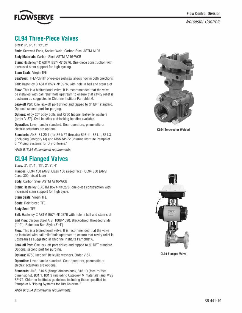
CL94 Three-Piece ValvesSizes: 1/2", 3/4", 1", 11/2", 2"
Ends: Screwed Ends, Socket Weld, Carbon Steel ASTM A105
Body Materials: Carbon Steel ASTM A216-WCB
Stem: Hastelloy® C ASTM B574-N10276, One-piece construction withincreased stem support for high cycling.
Stem Seals: Virgin TFE
Seat/Seal: TFE/Polyfill® one-piece seat/seal allows flow in both directions
Ball: Hastelloy C ASTM B574-N10276, with hole in ball and stem slot
Flow: This is a bidirectional valve. It is recommended that the valvebe installed with ball relief hole upstream to ensure that cavity relief isupstream as suggested in Chlorine Institute Pamphlet 6.
Leak-off Port: One leak-off port drilled and tapped to 1/8" NPT standard.Optional second port for purging.
Options: Alloy 20® body bolts and X750 Inconel Belleville washers(order V-57). Oval handles and locking handles available.
Operation: Lever handle standard. Gear operators, pneumatic orelectric actuators are optional.
Standards: ANSI B1.20.1 (for SE NPT threads) B16.11, B31.1, B31.3(including Category M) and MSS SP-72 Chlorine Institute Pamphlet6, “Piping Systems for Dry Chlorine.”
ANSI B16.34 dimensional requirements.
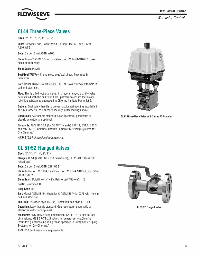
CL94 Flanged ValvesSizes: 1/2", 3/4", 1", 11/2", 2", 3", 4"
Flanges: CL94 150 (ANSI Class 150 raised face), CL94 300 (ANSIClass 300 raised face)
Body: Carbon Steel ASTM A216-WCB
Stem: Hastelloy C ASTM B574-N10276, one-piece construction withincreased stem support for high cycle.
Stem Seals: Virgin TFE
Seats: Reinforced TFE
Body Seal: TFE
Ball: Hastelloy C ASTM B574-N10276 with hole in ball and stem slot
End Plug: Carbon Steel AISI 1008-1030, Blackodized Threaded Style(1"-2"), Retention Bolt Style (3"-4")
Flow: This is a bidirectional valve. It is recommended that the valvebe installed with ball relief hole upstream to ensure that cavity relief isupstream as suggested in Chlorine Institute Pamphlet 6.
Leak-off Port: One leak-off port drilled and tapped to 1/8" NPT standard.Optional second port for purging.
Options: X750 Inconel® Belleville washers. Order V-57.
Operation: Lever handle standard. Gear operators, pneumatic orelectric actuators are optional.
Standards: ANSI B16.5 (flange dimensions), B16.10 (face-to-facedimensions), B31.1, B31.3 (including Category M materials) and MSSSP-72. Chlorine Institutes guidelines including those specified inPamphlet 6 “Piping Systems for Dry Chlorine.”
ANSI B16.34 dimensional requirements.
Flow Control Division
Worcester Controls
CL94 Screwed or Welded
CL94 Flanged Valve
SB 441-19 5
Flow Control Division
Worcester Controls
CL44 Three-Piece ValvesSizes: 1/4", 3/8", 1/2", 3/4", 1", 11/2", 2"
Ends: Screwed Ends, Socket Weld, Carbon Steel ASTM A105 or A216 WCB
Body: Carbon Steel ASTM A105
Stem: Monel® ASTM 164 or Hastelloy C ASTM B574-N10276. One-piece bottom entry.
Stem Seals: Polyfill
Seat/Seal:TFE/Polyfill one-piece seat/seal allows flow in bothdirections.
Ball: Monel ASTM 164, Hastelloy C ASTM B574-N10276 with hole inball and stem slot.
Flow: This is a bidirectional valve. It is recommended that the valvebe installed with the ball relief hole upstream to ensure that cavityrelief is upstream as suggested in Chlorine Institute Pamphlet 6.
Options: Oval safety handle to prevent accidental opening. Available inall sizes, order V-32. For more security, order locking handle.
Operation: Lever handle standard. Gear operators, pneumatic orelectric actuators are optional.
Standards: ANSI B1.20.1 (for SE NPT threads) B16.11, B31.1, B31.3and MSS SP-72 Chlorine Institute Pamphlet 6, “Piping Systems forDry Chlorine.”
ANSI B16.34 dimensional requirements.
CL 51/52 Flanged ValvesSizes: 1/2", 3/4", 1", 11/2", 2", 3", 4"
Flanges: CL51 (ANSI Class 150 raised face), CL52 (ANSI Class 300raised face)
Body: Carbon Steel ASTM 216-WCB
Stem: Monel ASTM B164, Hastelloy C ASTM B574-N10276, one-piecebottom entry
Stem Seals: Polyfill — (1/2" - 2"), Reinforced TFE — (3", 4")
Seats: Reinforced TFE
Body Seal: TFE
Ball: Monel ASTM B164, Hastelloy C ASTM B574-N10276 with hole inball and stem slot
End Plug: Threaded style (1/2" - 2"), Retention bolt style (3" - 4")
Operation: Lever handle standard. Gear operators, pneumatic orelectric actuators are optional.
Standards: ANSI B16.5 flange dimension, ANSI B16.10 face-to-facedimensions, MSS SP-72 ball valves for general service.ChlorineInstitute's guidelines including those specified in Pamphlet 6 “PipingSystems for Dry Chlorine.”
ANSI B16.34 dimensional requirements.
CL44 Three-Piece Valve with Series 75 Actuator
CL51/52 Flanged Valve
6 SB 441-19
Flow Control Division
Worcester Controls
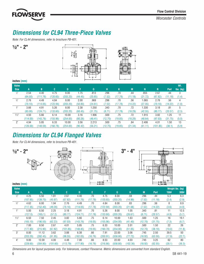
Valve Wt.Size A B C D F G H K M N R Port lbs. (kg)
1/2" 2.54 4.40 4.75 8.00 1.75 .813 .296 .70 .44 .855 2.67 .44 3(64.50) (111.76) (120.65) (203.20) (44.45) (20.65) (7.52) (17.78) (11.18) (21.72) (67.82) (11.18) (1.4)
3/4" 2.76 4.49 4.84 8.00 2.00 .969 .296 .70 .56 1.065 2.76 .56 4(70.10) (114.05) (122.94) (203.20) (50.80) (24.61) (7.52) (17.78) (14.22) (27.05) (70.10) (14.22) (1.8)
1" 3.66 4.91 5.26 8.00 2.38 1.250 .343 .70 .72 1.330 3.18 .81 5(93.00) (124.71) (133.60) (203.20) (60.45) (31.75) (8.71) (17.78) (18.29) (42.55) (80.77) (20.57) (2.3)
11/2" 4.50 5.66 6.14 10.00 3.16 1.906 .500 .75 .72 1.915 3.82 1.25 11(114.00) (143.76) (155.96) (254.00) (80.26) (48.41) (12.70) (19.05) (18.29) (48.64) (97.03) (31.75) (5.0)
2" 4.94 5.85 6.33 10.00 3.56 2.213 .500 .75 .84 2.406 4.01 1.50 13(126.00) (148.59) (160.78) (254.00) (90.42) (56.21) (12.70) (19.05) (21.34) (61.11) (101.85) (38.1) (5.9)
Dimensions for CL94 Three-Piece ValvesNote: For CL44 dimensions, refer to brochure PB-401.
Dimensions for CL94 Flanged ValvesNote: For CL44 dimensions, refer to brochure PB-401.
inches (mm)
Valve Weight lbs. (kg)Size A A1 B C D E F G H M Port 150# 300#
1/2" 4.25 5.50 1.81 2.67 4.40 .70 4.75 8.00 .59 .296 .44 5.3 6.3(107.95) (139.70) (45.97) (67.82) (111.76) (17.78) (120.65) (203.20) (14.99) (7.52) (11.18) (2.4) (2.9)
3/4" 4.62 6.00 1.94 2.76 4.49 .70 4.84 8.00 .83 .296 .56 8 8.9(117.35) (152.40) (49.28) (70.10) (114.05) (17.78) (122.94) (203.20) (21.08) (7.52) (14.22) (3.6) (4.0)
1" 5.00 6.50 2.25 3.18 4.91 .70 5.26 8.00 1.05 .343 .81 11 12.5(127.0) (165.1) (57.2) (80.77) (124.71) (17.78) (133.60) (203.20) (26.67) (8.71) (20.57) (4.9) (5.7)
11/2" 6.50 7.50 2.45 3.82 5.66 .75 6.14 10.00 1.63 .500 1.25 16 19.1(165.10) (190.50) (62.23) (97.03) (143.76) (19.05) (155.96) (254.00) (41.40) (12.70) (31.75) (7.3) (8.7)
2" 7.00 8.50 2.67 4.01 5.85 .75 6.33 10.00 2.01 .500 1.50 22 26(177.80) (215.90) (67.82) (101.85) (148.45) (19.05) (160.78) (254.00) (51.05) (12.70) (38.10) (10.0) (11.8)
3" 8.00 11.12 3.62 3.88 6.38 .66 7.91 22.00 3.06 .745 2.50 39.5 50(203.20) (282.45) (91.95) (98.55) (162.05) (16.76) (200.91) (558.80) (77.72) (18.92) (63.50) (17.9) (22.7)
4" 9.00 12.00 4.00 4.48 7.00 .66 8.53 22.00 4.03 .745 3.25 62 80(228.60) (304.80) (101.60) (113.79) (177.80) (16.76) (216.66) (558.80) (102.36) (18.92) (82.55) (28.1) (36.3)
inches (mm)
A?s" - 2"
A?s" - 2" 3" - 4"
Dimensions are for layout purposes only. For tolerances, contact Flowserve. Metric dimensions are converted from standard English.

SB 441-19 7
Flow Control Division
Worcester Controls
CL94 Three-Piece (A?s" - 2")Part No. Part Name Qty per Valve
1 Body 12 Pipe End 23 Ball 14 Stem 15 Seat/Seal 28 Split Ring 2 halves9 Thrust Bearing 110 Filler Ring 111 629 Seal 112 Lantern Ring 113 Chevron Ring 314 Follower 116 Handle 117 Set Screw 218 Gland Plate 119 Gland Bolt 220 Belleville Washer 1221 Body Bolt 422 Body Nut 423 Nameplate 124 Plug 1
8 SB 441-19
Flow Control Division
Worcester Controls
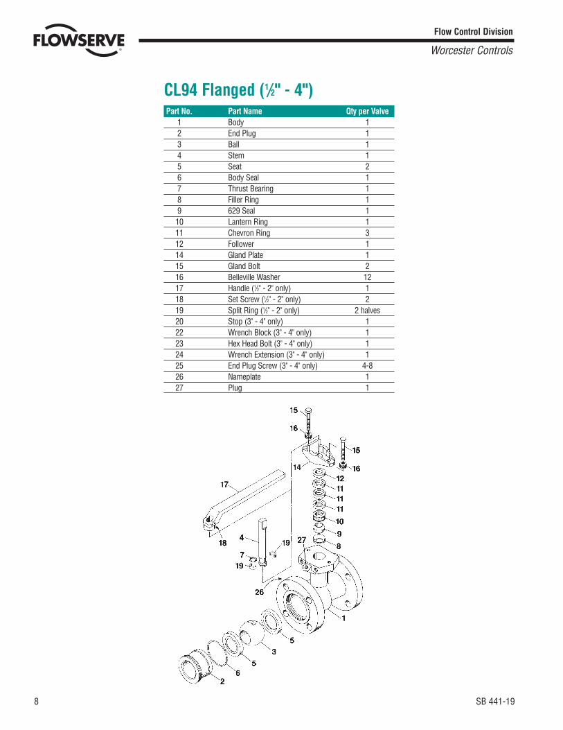
CL94 Flanged (1/2" - 4")Part No. Part Name Qty per Valve
1 Body 12 End Plug 13 Ball 14 Stem 15 Seat 26 Body Seal 17 Thrust Bearing 18 Filler Ring 19 629 Seal 110 Lantern Ring 111 Chevron Ring 312 Follower 114 Gland Plate 115 Gland Bolt 216 Belleville Washer 1217 Handle (1/2" - 2" only) 118 Set Screw (1/2" - 2" only) 219 Split Ring (1/2" - 2" only) 2 halves20 Stop (3" - 4" only) 122 Wrench Block (3" - 4" only) 123 Hex Head Bolt (3" - 4" only) 124 Wrench Extension (3" - 4" only) 125 End Plug Screw (3" - 4" only) 4-826 Nameplate 127 Plug 1

SB 441-19 9
Flow Control Division
Worcester Controls
15 2
5
3
71318
9
10
1112
16
11
52
14
4
17
8
1 1/4" - 2"
CL 44 (1/2" - 2")Part No. Part Name Qty. per Valve
1 Valve Body 12 Pipe Ends 23 Ball 14 Stem 15 Seat/Seal 27 Stem Seals 28 Thrust Bearing 19 Stem Seal Follower 110 Belleville Washers 211 Retaining Nuts 212 Handle Assembly 113 Stop Pin(s) 1 or 214 Body Bolts 415 Body Nuts 416 Lockwasher 117 Thrust Bearing 118 Seal Protector 1

10 SB 441-19
Flow Control Division
Worcester Controls
CL 51/52 (1/2" - 4")Part No. Part Name Qty per Valve
1 End Plug 12 Seat 23 Ball 14 Body Seal 15 Stop Pin(s) 1 or 26 Belleville Washers 2
(1/2" - 2")7 Stem Seals 2 or 38 Body 19 Thrust Bearing 1 or 210 Stem 111 End Plug Retention Bolts 4-8
(3" - 4" only)12 Stop Plate 113 Washer (3" - 4") 114 Retaining Nut 115 Handle 116 Handle Nut/Bolt 117 Follower 1
16
15
1412177
52
32
41
13
910
11
13
1618
15
14
6
7
52
32
41
10
9
17
19
A?s" - 2" 3" - 4"

SB 441-19 11
Flow Control Division
Worcester Controls
Blank - No VariationV6 - Source InspectionV36 - Certificate of CompliancV38 - Assemble without lubricantV57 - Alloy 20 Body Bolts, Nuts and X750 Inconel Belleville WashersV58 - B16.34 ComplianceV66 - Certificate of Compliance, European Valve Orders
Size Product Series
1/2"3/4"1"11/2"2"
CL94
Body, Pipe Ends
4 - Carbon Steel
Ball, Stem
C - Hastelloy C Ball & Stem
7 -
C7 -
C -
Monel Ball & StemHastelloy C Ball, Monel StemHastelloy C Ball, & Stem
Seat, Seal End Connection
T - TFEP - Polyfil
T - TFEP - Polyfil
SE - Screw EndSW - Socket WeldBW4 - Sch. 40BW8 - Sch. 80
SE - Screw EndSW - Socket WeldBW4 - Sch. 40
Variations Listings(V-Number Options)
Blank - No VariationV6 - Source InspectionV17 - Grounding Thrust BearingV32 - Oval HandleV36 - Certificate of CompliancV48 - Extended Lever HandleV58 - B16.34 ComplianceV59 - Extended Oval HandleV60 - OSHA LockoutV66 - Certificate of Compliance, European Valve Orders
CL44 4 - Carbon Steel
Chlorine Valves (Three-Piece)
CL94(150# or 300#)
Size Variations Available
150 - ANSI Class 150 Flanges300 - ANSI Class 300 Flanges
End ConnectionSeat, SealProduct Series
4 - Carbon Steel
Body, Pipe Ends
C - Hastelloy C Ball & Stem
Ball, Stem1/2"3/4"1"11/2"2"3"4"
1/2"3/4"1"11/2"2"3"4"
CL51-(150#)
CL52-(300#)
150 - ANSI Class 150 Flanges300 - ANSI Class 300 Flanges
4 - Carbon Steel 7 -
C7 -
C -
Monel Ball & StemHastelloy C Ball, Monel StemHastelloy C Ball, & Stem
RT - Reinforced TFE Seats & TFE Body Seal
RT - Reinforced TFE Seats & TFE Body Seal
Blank - No VariationV6 - Source InspectionV36 - Certificate of CompliancV57 - X750 Belleville WashersV58 - B16.34 ComplianceV66 - Certificate of Compliance European Valve Orders
Blank - No VariationV6 - Source InspectionV17 - Grounding Thrust BearingV32 - Oval Handle, (1/2" - 2" only)
V36 - Certificate of CompliancV48 - Extended Lever HandleV58 - B16.34 ComplianceV59 - Extended Oval HandleV66 - Certificate of Compliance European Valve Orders
Chlorine Valves (Flanged)
How to OrderExample: 3/4" CL944CTSE
How to Order CL94 HandlesOperating handles are ordered separately. If ordering a 2" CL94 valve,order a 2" HK94 handle. Please specify on the order whether you wishthe handle mounted at the factory or shipped separately.
Example: 2" HK94 handle – factory mounted.
CAUTION: Ball valves can retain pressurized media in the bodycavity when closed. Use care when disassembling. Always openvalve to relieve pressure prior to disassembly.
Due to continuous development of our product range, we reserve theright to alter the product specifications and information contained inthis leaflet as required.
NOTE: Although readily available, repair kits are unique to the ChlorineValves, and must be specifically ordered with the “CL” prefix.

Flow Control Division
Worcester Controls
Flowserve Corporation has established industry leadership in the design and manufacture of its products. When properly selected, this Flowserve product is designed to perform its intended functionsafely during its useful life. However, the purchaser or user of Flowserve products should be aware that Flowserve products might be used in numerous applications under a wide variety of industrialservice conditions. Although Flowserve can (and often does) provide general guidelines, it cannot provide specific data and warnings for all possible applications. The purchaser/user must thereforeassume the ultimate responsibility for the proper sizing and selection, installation, operation, and maintenance of Flowserve products. The purchaser/user should read and understand the InstallationOperation Maintenance (IOM) instructions included with the product, and train its employees and contractors in the safe use of Flowserve products in connection with the specific application.
While the information and specifications contained in this literature are believed to be accurate, they are supplied for informative purposes only and should not be considered certified or as a guarantee ofsatisfactory results by reliance thereon. Nothing contained herein is to be construed as a warranty or guarantee, express or implied, regarding any matter with respect to this product. Because Flowserveis continually improving and upgrading its product design, the specifications, dimensions and information contained herein are subject to change without notice. Should any question arise concerningthese provisions, the purchaser/user should contact Flowserve Corporation at any one of its worldwide operations or offices.
For more information about Flowserve Corporation, contact www.flowserve.com or call USA 1-800-225-6989.
FLOWSERVE CORPORATIONFLOW CONTROL DIVISION1978 Foreman DriveCookeville, Tennessee 38501 USAPhone: 931 432 4021Facsimile: 931 432 3105www.flowserve.com
© 2003 Flowserve Corporation, Irving, Texas, USA. Flowserve and Worcester Controls are registered trademarks of Flowserve Corporation. SB 441-19 8/03 Printed in USA
Polyfill® is a registered trademark of Worcester Controls Corporation.Hastelloy® C is a registered trademark of Union Carbide Corp.Monel® is a registered trademark of Inco Alloys international.Alloy® 20 is a registered trademark of CRS holdings, Inc.Inconel® is a registered trademark of Inco Alloys International.
Worcester ... All The Right Valves In All The Right Places