work in progress - jan - 2012s8a2f6e7acbae5e1b.jimcontent.com/download/version/1357817927/mo… ·...
TRANSCRIPT

Work in Progress December 21, 2012
Reporter: Dave Yotter
The December meeting began with what has become a tradition around the holidays. There were lots of goodies to snack on. There were many wives and significant others in attendance. The barbershop quartet was excellent again this year and very well received. I like the fact that although the tunes that we heard were very familiar and traditional along with the excellent four-part harmony, many of the lyrics were significantly updated.
HMS ROEBUCK – Don Dressel Don Dressel is continuing work on his 1:64 model of HMS ROEBUCK. The model is being built using the Hahn method of construction and to Hahn plans. Don says that the plans are good but the book by Hahn is really needed too. The hull planking is pau marfim and several strakes are installed. The wales are ebony.
Newsletter
Volume 39, Number 1, Jan. 2012
Contacts
President: Bill Schultheis (714) 366-7602
E-Mail [email protected] Vice President: Don Dressel
(909) 949-6931 E-Mail [email protected]
Secretary: Paul Payne (310) 544-1461
Treasurer: Mike DiCerbo (714) 523-2518
15320 Ocaso Ave, #DD204, La Mirada, CA. 90630
Editor, Don Dressel (909) 949-6931
908 W. 22nd Street Upland, CA 91784-1229
E-mail: [email protected] Web Manager: Doug Tolbert:
(949) 644-5416 Web Site
www.shipmodelersassociation.org
Meeting – Wed., Jan. 18, 7 PM, Red Cross Building, 1207 N. Lemon,
Fullerton, CA. 92832
Officers meeting – Wed., Feb. 1, 2012, 7 PM, Bob Beech’s house, 130 Clove Pl., Brea, CA. 92821 –
(714) 529-1481.
1

He is putting in the dowels (treenails) as he goes (bamboo) so as not to get too far ahead on the location of the treenails. The planks are softened for bending by simply soaking them in a tube filled with water. They soak for a day or so and then the water is changed again to hot water prior to bending. The woods used for the model were obtained from HobbyMill with the exception of the maple frames, which were obtained from Warner Woods West, which no longer sells wood. The HobbyMill woods used are pear, ebony and pau marfim for the
planking. Boxwood, also obtained from HobbyMill, will be used for the carvings (the figurehead is already carved). Don mentioned that the HMS ROEBUCK was an interesting ship in that, from a distance, they were often mistaken for 74’s or similar two-deckers. The HMS ROEBUCK was one of a class of 20 fifth rate ships, mostly 44-gun two-deckers. Some even had a double row of lights in the great cabin to help create the illusion of a larger warship. Russian Pre-dreadnaught battleship OSLYABYA – Burt Goldstein Burt Goldstein presented his cardstock model of a Russian pre-dreadnaught battleship OSLYABYA. The model is a “kit” from Digital Navy in 1:250 scale. In this case, Burt received his model on a disc, so he could then print out all the parts on his own printer rather than have everything presented in a book. The printout consisted of 10 sheets of parts and six to seven sheets of instructions. It seems to this reporter that this format would be preferable over a book due to the unlimited availability of “spare parts” in case of a mishap in assembly. Burt built the model as a full hull rather than a waterline model and it is quite impressive with no fewer than 16 ships boats and a primary armament consisting of four 10 in. guns mounted in two twin turrets, one fore and one aft. Secondary armament was eleven 6 in. guns along with a tertiary armament of twenty seventy-five millimeter guns, twenty forty-seven millimeter and six thirty-seven millimeter guns. The ship also had five above-water 381-millimeter torpedo tubes. OSLYABYA was sunk in Tsushima Straits in 1905 in the first large engagement of the modern “Big Gun” navies. The battle ended with a big victory for the Japanese and the practical annihilation of the entire Russian Second Pacific Squadron.
2
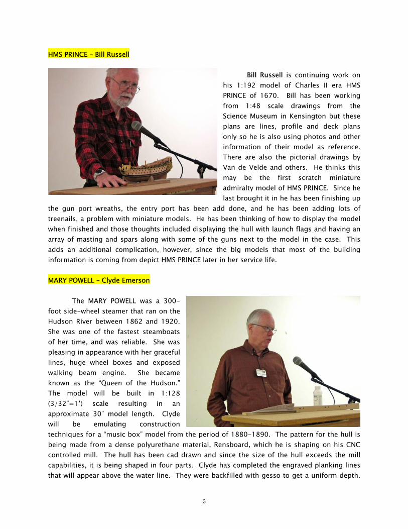
HMS PRINCE – Bill Russell Bill Russell is continuing work on his 1:192 model of Charles II era HMS PRINCE of 1670. Bill has been working from 1:48 scale drawings from the Science Museum in Kensington but these plans are lines, profile and deck plans only so he is also using photos and other information of their model as reference. There are also the pictorial drawings by Van de Velde and others. He thinks this may be the first scratch miniature admiralty model of HMS PRINCE. Since he last brought it in he has been finishing up
the gun port wreaths, the entry port has been add done, and he has been adding lots of treenails, a problem with miniature models. He has been thinking of how to display the model when finished and those thoughts included displaying the hull with launch flags and having an array of masting and spars along with some of the guns next to the model in the case. This adds an additional complication, however, since the big models that most of the building information is coming from depict HMS PRINCE later in her service life. MARY POWELL – Clyde Emerson The MARY POWELL was a 300-foot side-wheel steamer that ran on the Hudson River between 1862 and 1920. She was one of the fastest steamboats of her time, and was reliable. She was pleasing in appearance with her graceful lines, huge wheel boxes and exposed walking beam engine. She became known as the “Queen of the Hudson.” The model will be built in 1:128 (3/32”=1’) scale resulting in an approximate 30” model length. Clyde will be emulating construction techniques for a “music box” model from the period of 1880-1890. The pattern for the hull is being made from a dense polyurethane material, Rensboard, which he is shaping on his CNC controlled mill. The hull has been cad drawn and since the size of the hull exceeds the mill capabilities, it is being shaped in four parts. Clyde has completed the engraved planking lines that will appear above the water line. They were backfilled with gesso to get a uniform depth.
3
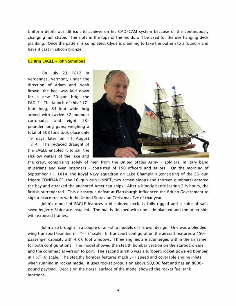
Uniform depth was difficult to achieve on his CAD/CAM system because of the continuously changing hull shape. The slots in the tops of the molds will be used for the overhanging deck planking. Once the pattern is completed, Clyde is planning to take the pattern to a foundry and have it cast in silicon bronze. US Brig EAGLE – John Simmons On July 23 1812 in Vergennes, Vermont, under the direction of Adam and Noah Brown, the keel was laid down for a new 20-gun brig: the EAGLE. The launch of this 117-foot long, 34-foot wide brig armed with twelve 32-pounder carronades and eight 18-pounder long guns, weighing a total of 508 tons took place only 19 days later on 11 August 1814. The reduced draught of the EAGLE enabled it to sail the shallow waters of the lake and the crew, comprising solely of men from the United States Army – soldiers, military band musicians and even prisoners – consisted of 150 officers and sailors. On the morning of September 11, 1814, the Royal Navy squadron on Lake Champlain (consisting of the 36-gun frigate CONFIANCE, the 16-gun brig LINNET, two armed sloops and thirteen gunboats) entered the bay and attacked the anchored American ships. After a bloody battle lasting 2 ½ hours, the British surrendered. This disastrous defeat at Plattsburgh influenced the British Government to sign a peace treaty with the United States on Christmas Eve of that year. John’s model of EAGLE features a bi-colored deck, is fully rigged and a suite of sails sewn by Jerry Blaire are installed. The hull is finished with one side planked and the other side with exposed frames. John also brought in a couple of air-ship models of his own design. One was a blended wing transport/bomber in 1”=15’ scale. In transport configuration the aircraft features a 450-passenger capacity with 4 X 6 foot windows. Three engines are submerged within the airframe for both configurations. The model showed the stealth bomber version on the starboard side and the commercial version to port. The second airship was a turbojet/rocket powered bomber in 1 ½”=6’ scale. The stealthy bomber features mach 5-7 speed and coverable engine inlets when running in rocket mode. It uses rocket propulsion above 50,000 feet and has an 8000-pound payload. Decals on the dorsal surface of the model showed the rocket fuel tank locations.
4

IJN Type “A” 2-man Midget Submarine (1941) – Paul Alkon Paul Alkon brought in a finished 1:72 Wings 72 kit of an Imperial Japanese Navy Type “A” 2-man midget submarine. In addition to the sub and to illustrate its scale he brought in a 1:72 scale model of a P-40 fighter of the type the Americans would have flown to defend Pearl Harbor during the attack. He noted that recently Fine Molds had released an injection molded plastic kit of this sub. Paul also noted that the wires running for and aft from the conning
tower to the bow and stern were not radio antenna but were net cutting wires. Five of these subs were used during the Japanese attack on Pearl Harbor. One of the subs, the subject of this model, ran aground on a reef off Bellows airfield and was captured along with its captain. The wings vacuformed kit was introduced at the 45th reunion of the Pearl Harbor Survivors Association, Honolulu, Hawaii on December 7th, 1986. The best book on the midgets and other submarines sent to Hawaii for the attack is by Burl Burlingame, Advance Force Pearl Harbor, Pacific Monograph, 1992. CLARA MAY – Paul Carter Paul Carter has finished his 1:50 scale Artesania Latina kit of the CLARA MAY. The model features sails sewn by Jerry Blare of Aptos, CA. The boat was launched in 1891 in Plymouth England. The CLARA MAY was a cargo ketch plying the English Channel. Paul placed a flag aboard, black with a white cross, representing the patron saint of Cornwall. In the 1920’s the ketch was fitted with a hybrid 2-lung steam engine. She lasted until 1953 and was then scrapped. The wood sued on the model included cherry, walnut and bass. Paul did a great job on this model – it shows very clean lines and a beautiful run of planking.
5

IJN YAMATO – Sean Fallesen Sean Fallesen brought in a new Tamiya kit model of IJN YAMATO in 1:350 scale. The old kit was released 25 years ago and this new kit appears to be a huge leap forward in detail, construction and complexity. Whereas the old model kit was basically a hollow shell, the new one includes such details as the inside bulkheads of the aircraft hanger deck and such things as complete barbettes sunk into the deck. The superstructure houses are now made of dozens of individual castings,
each with much additional detail cast on. The instructions are three to four times the thickness of the old model and also the price, around $450.00, is about four times that of the old model. Sean did note that there were a few problems such as hard to clean up seams on deck plating detail and mold dimples showing in some of the flatter areas. All in all, Sean was impressed with the improvements and indicated that the quality and detail of the newer plastic ship models now being released far surpass the old plastic kits of years ago.
Don Dressel’s HMS ROEBUCK Burt Goldstein’s Russian OSLYABYA
6
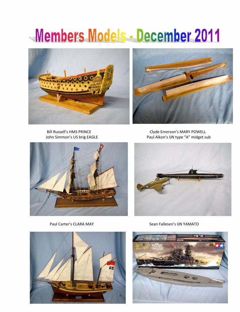
Bill Russell’s HMS PRINCE Clyde Emerson’s MARY POWELL John Simmon’s US brig EAGLE Paul Alkon’s IJN type “A” midget sub
Paul Carter’s CLARA MAY Sean Fallesen’s IJN YAMATO
7
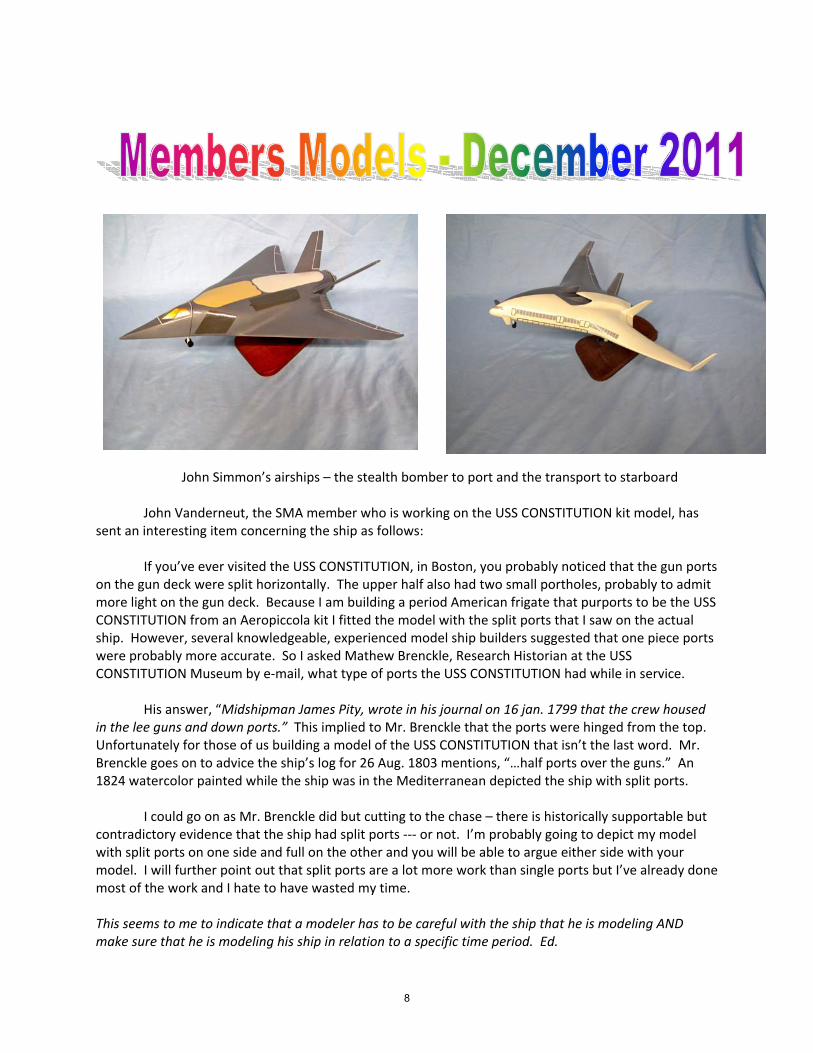
John Simmon’s airships – the stealth bomber to port and the transport to starboard John Vanderneut, the SMA member who is working on the USS CONSTITUTION kit model, has sent an interesting item concerning the ship as follows: If you’ve ever visited the USS CONSTITUTION, in Boston, you probably noticed that the gun ports on the gun deck were split horizontally. The upper half also had two small portholes, probably to admit more light on the gun deck. Because I am building a period American frigate that purports to be the USS CONSTITUTION from an Aeropiccola kit I fitted the model with the split ports that I saw on the actual ship. However, several knowledgeable, experienced model ship builders suggested that one piece ports were probably more accurate. So I asked Mathew Brenckle, Research Historian at the USS CONSTITUTION Museum by e‐mail, what type of ports the USS CONSTITUTION had while in service. His answer, “Midshipman James Pity, wrote in his journal on 16 jan. 1799 that the crew housed in the lee guns and down ports.” This implied to Mr. Brenckle that the ports were hinged from the top. Unfortunately for those of us building a model of the USS CONSTITUTION that isn’t the last word. Mr. Brenckle goes on to advice the ship’s log for 26 Aug. 1803 mentions, “…half ports over the guns.” An 1824 watercolor painted while the ship was in the Mediterranean depicted the ship with split ports. I could go on as Mr. Brenckle did but cutting to the chase – there is historically supportable but contradictory evidence that the ship had split ports ‐‐‐ or not. I’m probably going to depict my model with split ports on one side and full on the other and you will be able to argue either side with your model. I will further point out that split ports are a lot more work than single ports but I’ve already done most of the work and I hate to have wasted my time. This seems to me to indicate that a modeler has to be careful with the ship that he is modeling AND make sure that he is modeling his ship in relation to a specific time period. Ed.
8

TECHNIQUES AND TIPS By Frank Wilhite
Frank Wilhite, a longtime member of the SMA, has submitted the following techniques he used in constructing his ISSAQUAH ferry between 1997 and 1999. He is still an active member and accomplished modeler although he currently has difficulties attending the SMA meetings. He wanted to share the techniques he has used as follows: Asphalt Auto Deck The ferry ISSAQUAH was launched at the Anderson Steamboat Company in Houghton, WA on March 7, 1914. The auto deck of this ferry was unusual in two ways. First, it was one of the first ferries designed with double runways on the lower deck for autos and horse/mule teams. Second, the lower deck has and asphalt surface, at a time when asphalt was not common even for roads in the state of Washington. A member of the first ISSAQUAH crew, Tage Carlson, is quoted as saying:”One hot summer day, we took on board a load of King county road builders with horses, scrapers and graders. When the ferry blew her whistle, the horses became nervous and the first thing they did was relieve themselves. Also, because of the heat they left hoof prints in the softened asphalt which filled with the urine. They sure initiated that fancy new ferryboat.” Since this was an interesting part of the ISSAQUAH history, I felt it imperative to illustrate it on the model. I used a putty knife to smooth out joint compound for the lower deck surface, and I fabricated a “horseshoe” stamp
(photo 1) 1/8” in size (scale 6” shoe). After the joint compound had set somewhat, I used the stamp to make indented horseshoe prints in a random pattern. I also used model wagon wheels to make tracks (photo 2). After the joint compound had completely hardened, I painted the deck with an “asphalt” color paint. As you know, an asphalt street may appear black when first laid, but the color changes to a gray after a few
weeks in the sun. I blended two parts Concrete and one part Lark Light Gray Floquil paint to match the color of the street in front of my house. Windows The ISSAQUAH has 108 windows of various sizes. The auto deck bulwark has 42 of the largest windows, 21 on each side. I made a bulwark carving fixture out of a 2X4 (photo 3) to hold the bulwark at the proper curve while installing window assemblies. The windows were cut from 0.008” thick microscope covers using a handmade glass cutting jig. I tried using 0.010” thick clear styrene, but I did not like the appearance. Glass looks flatter and has better reflection than plastic (see photo 4 on next page). I used a 0.3 mm pen and India Ink to draw lines representing the four glass segments at the top of each window.
9
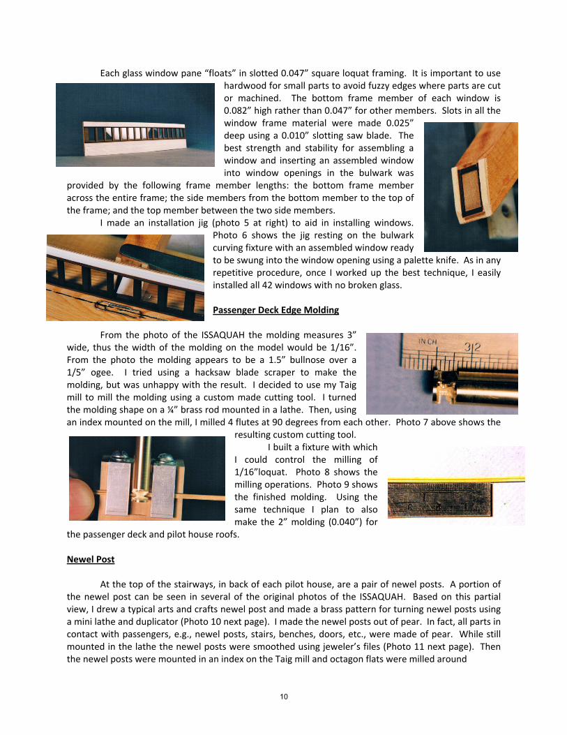
Each glass window pane “floats” in slotted 0.047” square loquat framing. It is important to use hardwood for small parts to avoid fuzzy edges where parts are cut or machined. The bottom frame member of each window is 0.082” high rather than 0.047” for other members. Slots in all the window frame material were made 0.025” deep using a 0.010” slotting saw blade. The best strength and stability for assembling a window and inserting an assembled window into window openings in the bulwark was
provided by the following frame member lengths: the bottom frame member across the entire frame; the side members from the bottom member to the top of the frame; and the top member between the two side members. I made an installation jig (photo 5 at right) to aid in installing windows.
Photo 6 shows the jig resting on the bulwark curving fixture with an assembled window ready to be swung into the window opening using a palette knife. As in any repetitive procedure, once I worked up the best technique, I easily installed all 42 windows with no broken glass. Passenger Deck Edge Molding
From the photo of the ISSAQUAH the molding measures 3” wide, thus the width of the molding on the model would be 1/16”. From the photo the molding appears to be a 1.5” bullnose over a 1/5” ogee. I tried using a hacksaw blade scraper to make the molding, but was unhappy with the result. I decided to use my Taig mill to mill the molding using a custom made cutting tool. I turned the molding shape on a ¼” brass rod mounted in a lathe. Then, using an index mounted on the mill, I milled 4 flutes at 90 degrees from each other. Photo 7 above shows the
resulting custom cutting tool. I built a fixture with which I could control the milling of 1/16”loquat. Photo 8 shows the milling operations. Photo 9 shows the finished molding. Using the same technique I plan to also make the 2” molding (0.040”) for
the passenger deck and pilot house roofs. Newel Post At the top of the stairways, in back of each pilot house, are a pair of newel posts. A portion of the newel post can be seen in several of the original photos of the ISSAQUAH. Based on this partial view, I drew a typical arts and crafts newel post and made a brass pattern for turning newel posts using a mini lathe and duplicator (Photo 10 next page). I made the newel posts out of pear. In fact, all parts in contact with passengers, e.g., newel posts, stairs, benches, doors, etc., were made of pear. While still mounted in the lathe the newel posts were smoothed using jeweler’s files (Photo 11 next page). Then the newel posts were mounted in an index on the Taig mill and octagon flats were milled around
10
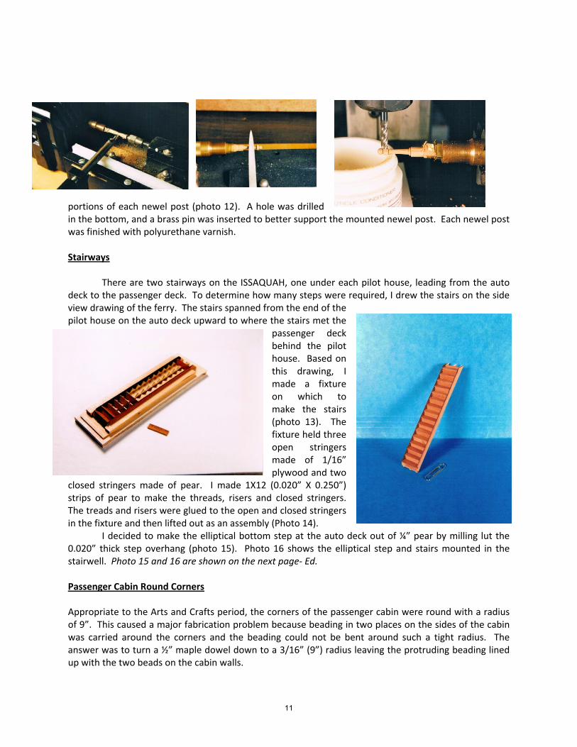
portions of each newel post (photo 12). A hole was drilled in the bottom, and a brass pin was inserted to better support the mounted newel post. Each newel post was finished with polyurethane varnish. Stairways There are two stairways on the ISSAQUAH, one under each pilot house, leading from the auto deck to the passenger deck. To determine how many steps were required, I drew the stairs on the side view drawing of the ferry. The stairs spanned from the end of the pilot house on the auto deck upward to where the stairs met the
passenger deck behind the pilot house. Based on this drawing, I made a fixture on which to make the stairs (photo 13). The fixture held three open stringers made of 1/16” plywood and two
closed stringers made of pear. I made 1X12 (0.020” X 0.250”) strips of pear to make the threads, risers and closed stringers. The treads and risers were glued to the open and closed stringers in the fixture and then lifted out as an assembly (Photo 14). I decided to make the elliptical bottom step at the auto deck out of ¼” pear by milling lut the 0.020” thick step overhang (photo 15). Photo 16 shows the elliptical step and stairs mounted in the stairwell. Photo 15 and 16 are shown on the next page‐ Ed. Passenger Cabin Round Corners Appropriate to the Arts and Crafts period, the corners of the passenger cabin were round with a radius of 9”. This caused a major fabrication problem because beading in two places on the sides of the cabin was carried around the corners and the beading could not be bent around such a tight radius. The answer was to turn a ½” maple dowel down to a 3/16” (9”) radius leaving the protruding beading lined up with the two beads on the cabin walls.
11

The dowel was then placed in the index and two dados were milled at an angle of 83 degrees from each other to match the angle between the two walls. The depth of the dado was 0.080” to receive each wall. The angle was not 90 degrees due to the fact that the side walls are curved. The beading on the side wall and corner was beveled so the joint is practically invisible. I also sanded top and bottom of the corner 87 degrees to follow the deck camber. The result of all this work is shown in the last photo. Many thanks to Frank for sending me this information and writing the article.
The editor would like to encourage other members of the SMA to send articles of interest to be published in the SMA Newsletter for the enjoyment of their fellow members. There are a lot of different methods of ship model construction that would be of great interest to all modelers. The techniques and methods used
to complete a ship modeling project can be extended to other areas with very satisfying results. Articles will be included in the SMA Newsletter as space allows.
12

Nominations for Vice-President for 2012 Nominations are still on call for Vice-President of the SMA for 2012. We currently had no Vice-President and the office was being filled temporarily by Don Dressel. However, at the SMA Officers meeting on January 4th John Simmons volunteered to become the Vice-President, so starting in February, John is the VP. 2012 Dues are Due This is a reminder that the SMA dues are due for next year. Any questions regarding dues can be addressed to any officer of the SMA. Treasurer Mike DiCerbo will be at the meeting to accept your cash or checks. The deadline is this coming March. Possible Admiralty Model’s work shop in California Guy Bell has contacted Greg Herbert of Admiralty Models to inquire what it would take to have a work shop locally. The cost would be $250.00 each. Names will start to be collected this month. When a total of 20 hearty ship modelers are signed up, then determination will be made as to when the work shop will take place and where. Contact Don Dressel if you are interested in this special opportunity. Treasurer’s Report Our esteemed SMA Treasurer, Mike DiCerbo, indicates that the current balance in the SMA treasury is $2,485.84 as of the end of December 2011. Web Manager’s Report
Above is the chart of the hits experienced by our SMA web page through the end of December of this year. You should check out the web page as there will is great set of articles on the speakers who were at the recent WSMC&E, according to Doug. There is a upsurge of interest in the SMA according to the charts. Good job, Doug.
13
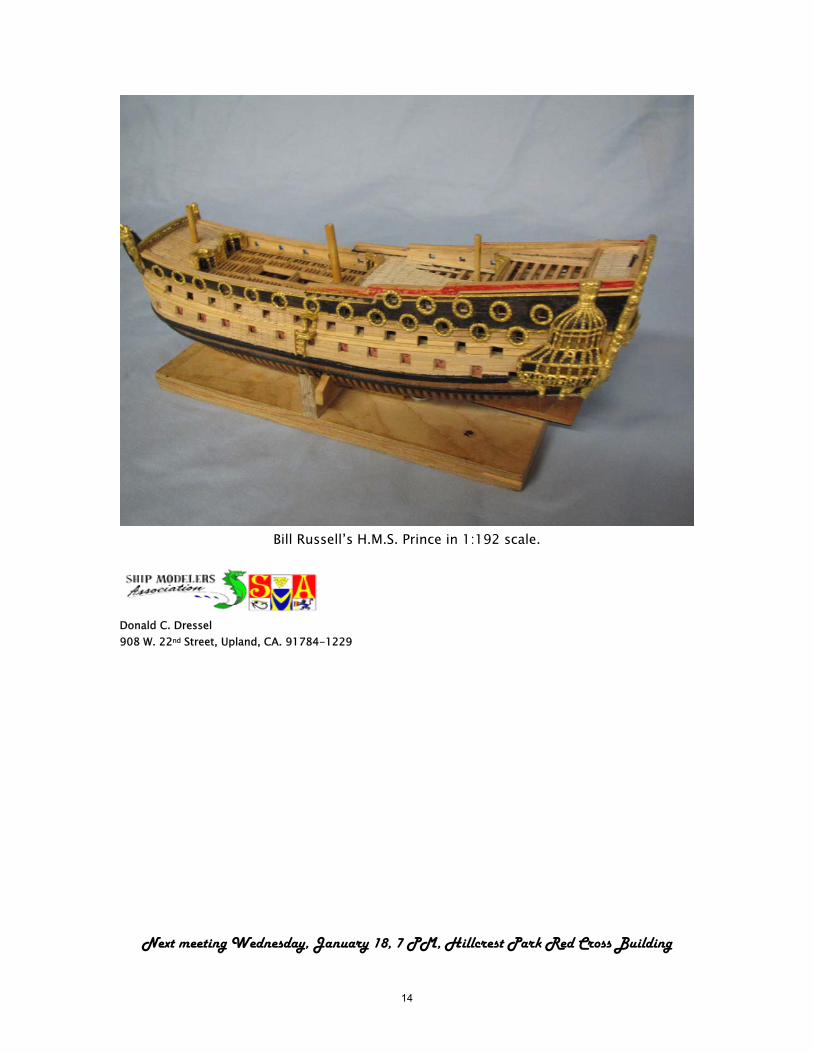
Bill Russell’s H.M.S. Prince in 1:192 scale.
Donald C. Dressel 908 W. 22nd Street, Upland, CA. 91784-1229
Next meeting Wednesday, January 18, 7 PM, Hillcrest Park Red Cross Building
14