worked example of nchrp 10-86 recommended...
TRANSCRIPT
NCHRP 10-86
APPENDIX B
Worked Example of NCHRP 10-86 Recommended Practice
1.0 INTRODUCTION This worked example is illustrative, rather than comprehensive, in the sense that al the key features of the RP are demonstrated, but without making use of a comprehensive pipe system inventory.
Stages 1A, 1B, and 1C (Roadway and Geometrical, Hydrology and Baseline Hydraulic, and Geotechnical and Environmental) and all stages of Phase 2 (Hydraulic, Structural and Durability) will be demonstrated. Phases 3 and Stages 4A and 4B are also demonstrated.
Design variations are included to illustrate features of the RP that would otherwise not have been demonstrated using the base case of this example. These design variations are not carried through the entire example. Rather, they are focussed on specific sections to assist the user in understanding the applicable range of the RP.
This worked example does not include recommended preparatory actions prior to implementation of the recommended practice. Such actions may include:
• Identification of the requirements, constraints and opportunities associated with any new or revised alternative pipe bidding system
• Compilation of an approved pipe system inventory • Definition of standard code or database system to uniquely identify pipe system installations
This example is substantially based on a project let in June 2012 by the Missouri DOT (MoDOT), but a number of assumptions have been made in developing the example to illustrate the RP. For the purposes of this example, best available practices were used where available, in place of MoDOT standards.
B-1
NCHRP 10-86
2.0 PHASE 1 – DATA GATHERING AND PROJECT DEFINITION
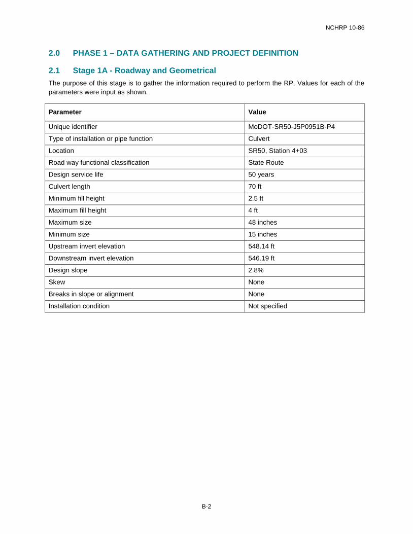
2.1 Stage 1A - Roadway and Geometrical The purpose of this stage is to gather the information required to perform the RP. Values for each of the parameters were input as shown.
Parameter Value
Unique identifier MoDOT-SR50-J5P0951B-P4
Type of installation or pipe function Culvert
Location SR50, Station 4+03
Road way functional classification State Route
Design service life 50 years
Culvert length 70 ft
Minimum fill height 2.5 ft
Maximum fill height 4 ft
Maximum size 48 inches
Minimum size 15 inches
Upstream invert elevation 548.14 ft
Downstream invert elevation 546.19 ft
Design slope 2.8%
Skew None
Breaks in slope or alignment None
Installation condition Not specified
B-2
NCHRP 10-86
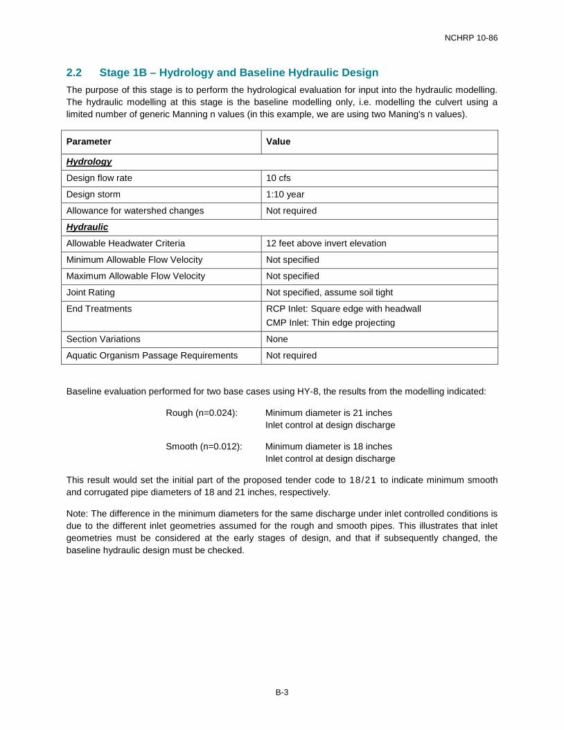
2.2 Stage 1B – Hydrology and Baseline Hydraulic Design The purpose of this stage is to perform the hydrological evaluation for input into the hydraulic modelling. The hydraulic modelling at this stage is the baseline modelling only, i.e. modelling the culvert using a limited number of generic Manning n values (in this example, we are using two Maning's n values).
Parameter Value
Hydrology
Design flow rate 10 cfs
Design storm 1:10 year
Allowance for watershed changes Not required
Hydraulic
Allowable Headwater Criteria 12 feet above invert elevation
Minimum Allowable Flow Velocity Not specified
Maximum Allowable Flow Velocity Not specified
Joint Rating Not specified, assume soil tight
End Treatments RCP Inlet: Square edge with headwall CMP Inlet: Thin edge projecting
Section Variations None
Aquatic Organism Passage Requirements Not required
Baseline evaluation performed for two base cases using HY-8, the results from the modelling indicated:
Rough (n=0.024): Minimum diameter is 21 inches Inlet control at design discharge
Smooth (n=0.012): Minimum diameter is 18 inches Inlet control at design discharge
This result would set the initial part of the proposed tender code to 18/21 to indicate minimum smooth and corrugated pipe diameters of 18 and 21 inches, respectively.
Note: The difference in the minimum diameters for the same discharge under inlet controlled conditions is due to the different inlet geometries assumed for the rough and smooth pipes. This illustrates that inlet geometries must be considered at the early stages of design, and that if subsequently changed, the baseline hydraulic design must be checked.
B-3
NCHRP 10-86
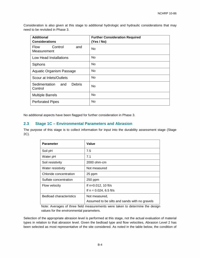
Consideration is also given at this stage to additional hydrologic and hydraulic considerations that may need to be revisited in Phase 3.
Additional Considerations
Further Consideration Required (Yes / No)
Flow Control and Measurement
No
Low Head Installations No
Siphons No
Aquatic Organism Passage No
Scour at Inlets/Outlets No
Sedimentation and Debris Control
No
Multiple Barrels No
Perforated Pipes No
No additional aspects have been flagged for further consideration in Phase 3.
2.3 Stage 1C – Environmental Parameters and Abrasion The purpose of this stage is to collect information for input into the durability assessment stage (Stage 2C).
Parameter Value
Soil pH 7.5
Water pH 7.1
Soil resistivity 2000 ohm-cm
Water resistivity Not measured
Chloride concentration 25 ppm
Sulfate concentration 250 ppm
Flow velocity If n=0.012, 10 ft/s If n = 0.024, 6.5 ft/s
Bedload characteristics Not measured, Assumed to be silts and sands with no gravels
Note: Averages of three field measurements were taken to determine the design values for the environmental parameters.
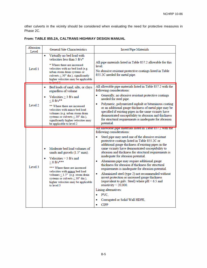
Selection of the appropriate abrasion level is performed at this stage, not the actual evaluation of material types in relation to that abrasion level. Given the bedload type and flow velocities, Abrasion Level 2 has been selected as most representative of the site considered. As noted in the table below, the condition of
B-4
NCHRP 10-86
other culverts in the vicinity should be considered when evaluating the need for protective measures in Phase 2C.
From: TABLE 855.2A, CALTRANS HIGHWAY DESIGN MANUAL
B-5
NCHRP 10-86
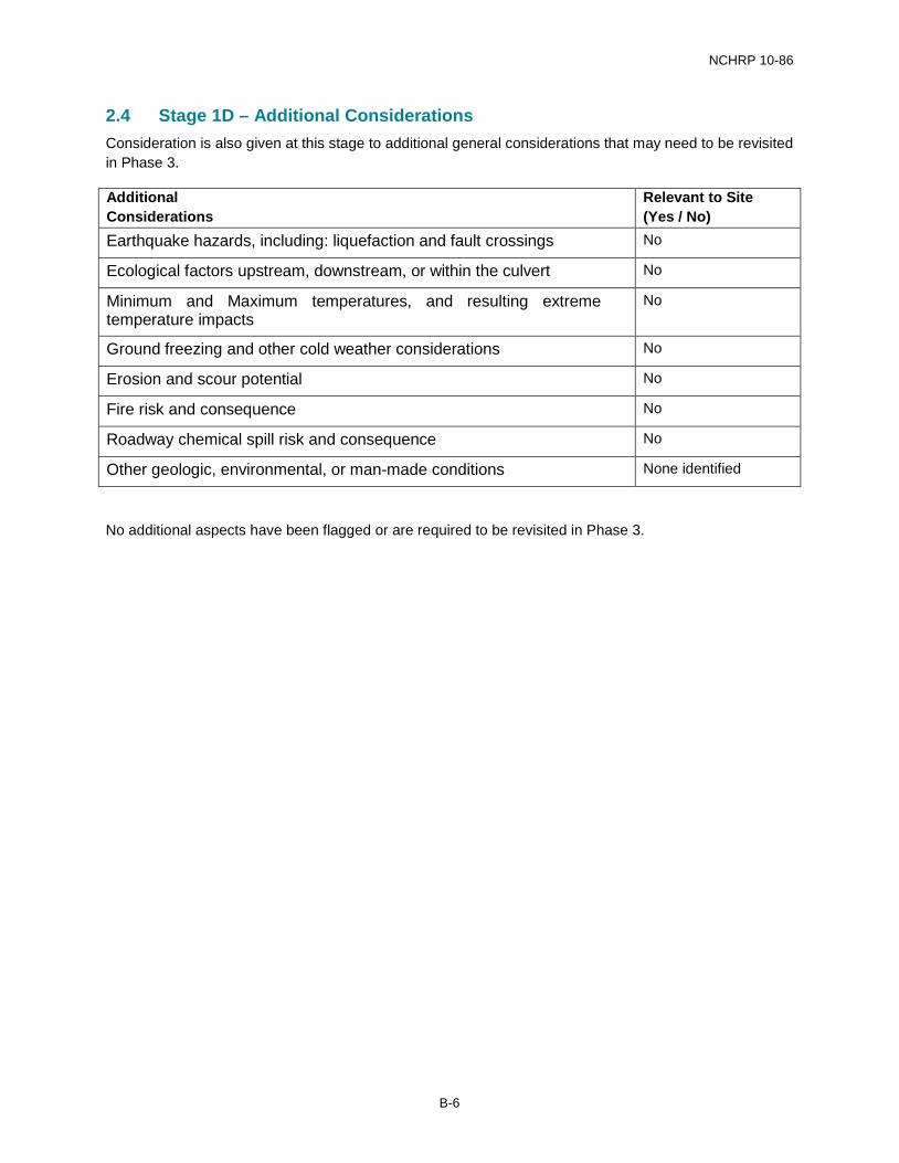
2.4 Stage 1D – Additional Considerations Consideration is also given at this stage to additional general considerations that may need to be revisited in Phase 3.
Additional Considerations
Relevant to Site (Yes / No)
Earthquake hazards, including: liquefaction and fault crossings No
Ecological factors upstream, downstream, or within the culvert No
Minimum and Maximum temperatures, and resulting extreme temperature impacts
No
Ground freezing and other cold weather considerations No
Erosion and scour potential No
Fire risk and consequence No
Roadway chemical spill risk and consequence No
Other geologic, environmental, or man-made conditions None identified
No additional aspects have been flagged or are required to be revisited in Phase 3.
B-6
NCHRP 10-86
3.0 PHASE 2 – TECHNICAL EVALUATIONS
3.1 Stage 2A – Hydraulic Evaluations The purpose of this stage is to evaluate each pipe system (combination of pipe roughness and diameter) to determine if the pipe system can carry the design discharge.
The baseline hydraulic evaluation is used as a reference, and hydraulic equivalency charts are used to streamline the evaluation (on a basis of either being acceptable or not acceptable).
The outcome of this stage is a matrix showing all pipe systems considered, and if they have adequate hydraulic capacity or not.
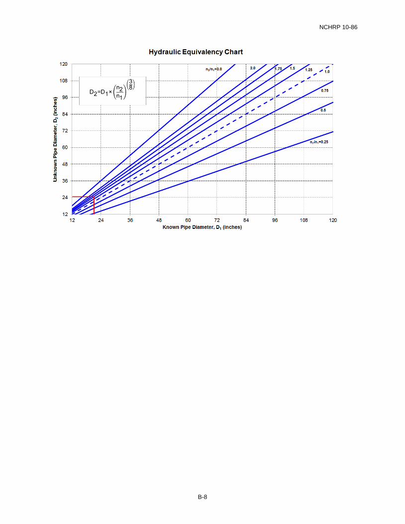
3.1.1 Calculation Example The user wishes to perform an evaluation of a structural plate section with Manning value of 0.036, which was not previously evaluated.
Use the hydraulic equivalency chart as shown below:
Known pipe diameter, D1 = 21 inches Known pipe Manning n, n1 = 0.024 Unknown pipe Manning n, n2 = 0.036 n2/n1 = 1.5
From the chart, Unknown Pipe Diameter, D2 = 24.5 inches.
Given the assumptions in the use of the hydraulic equivalency chart, a diameter of 24 inches for a section with Manning n of 0.036 is deemed to be suitable. This could be further confirmed at a later stage if desired.
B-7
NCHRP 10-86
B-8
NCHRP 10-86
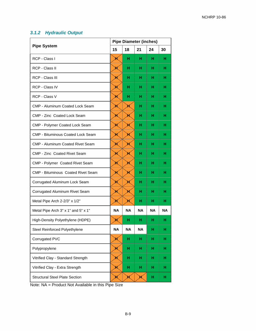
3.1.2 Hydraulic Output
Pipe System Pipe Diameter (inches)
15 18 21 24 30
RCP - Class I H H H H H
RCP - Class II H H H H H
RCP - Class III H H H H H
RCP - Class IV H H H H H
RCP - Class V H H H H H
CMP - Aluminum Coated Lock Seam H H H H H
CMP - Zinc Coated Lock Seam H H H H H
CMP - Polymer Coated Lock Seam H H H H H
CMP - Bituminous Coated Lock Seam H H H H H
CMP - Aluminum Coated Rivet Seam H H H H H
CMP - Zinc Coated Rivet Seam H H H H H
CMP - Polymer Coated Rivet Seam H H H H H
CMP - Bituminous Coated Rivet Seam H H H H H
Corrugated Aluminum Lock Seam H H H H H
Corrugated Aluminum Rivet Seam H H H H H
Metal Pipe Arch 2-2/3" x 1/2" H H H H H
Metal Pipe Arch 3" x 1" and 5" x 1" NA NA NA NA NA
High-Density Polyethylene (HDPE) H H H H H
Steel Reinforced Polyethylene NA NA NA H H
Corrugated PVC H H H H H
Polypropylene H H H H H
Vitrified Clay - Standard Strength H H H H H
Vitrified Clay - Extra Strength H H H H H
Structural Steel Plate Section H H H H H
Note: NA = Product Not Available in this Pipe Size
B-9

NCHRP 10-86
3.1.3 Illustrative Design Variation – Variation in Manning n value Known pipe diameter, D1 = 72 inches Known pipe Manning n, n1 = 0.036 Unknown pipe Manning n, n2 = 0.009 n2/n1 = 0.25
From the chart, Unknown Pipe Diameter, D2 = 43 inches.
Alternatively, the equation shown could be used:
D2 = (72) x (0.25)(3/8) D2 = 42.8 inches
Larger diameter pipes than those determined from the calculation are deemed to be hydraulically suitable.
B-10
NCHRP 10-86
3.2 Stage 2B – Structural Structural capacity is checked using the most recent version of the AASHTO LRFD Bridge Design Specification, where applicable. For RCP and CMP (corrugated steel and aluminium) this is facilitated using industry-supplied fill height tables and calculation methods.
For other material types, widely accepted methods that are readily implemented are not yet available, and so fixed fill height values irrespective of pipe diameter or installation condition have been assumed.
Both the maximum and minimum fill heights must be checked.
3.2.1 Minimum Fill Height Evaluation Minimum fill height is typically driven by requirements during construction, and the most common value is 2 feet. Assume that the allowable minimum fill height is 2 feet.
Pipe P4 minimum fill height = 2.5 feet
Minimum fill height > Allowable minimum fill height pipe PASSES the minimum fill height check.
Note: If thick-walled pipes are being considered, the thickness of the pipe wall must be considered when evaluating minimum fill height.
3.2.2 Maximum Fill Height Evaluation The maximum fill height for pipe P4 is 4 feet.
Each pipe material type must be evaluated separately.
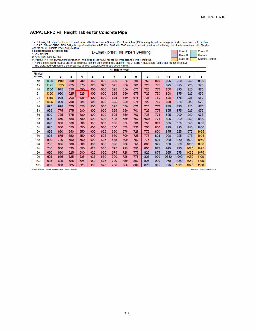
3.2.3 RCP Structural Evaluation Since we are evaluating the pipe material in this example, start the evaluation with the highest quality bedding type (Type 1) to determine the lowest quality pipe that (D-load class) that is structurally adequate.
Note that “Special Design” will always be an option for concrete pipe. However, given that the intent of the RP is to streamline the design and specification for typical installations, the ‘Special Design” option should not form part of routine use.
See table below, for 4 ft fill height, 21 inch diameter pipe – 625 D-load (lb/ft/ft) required, which is a Class I RCP. This provides the lowest class RCP pipe that would be required. All higher quality pipes, Class II and above, are deemed to be structurally suitable.
B-11
NCHRP 10-86
ACPA: LRFD Fill Height Tables for Concrete Pipe
B-12
NCHRP 10-86
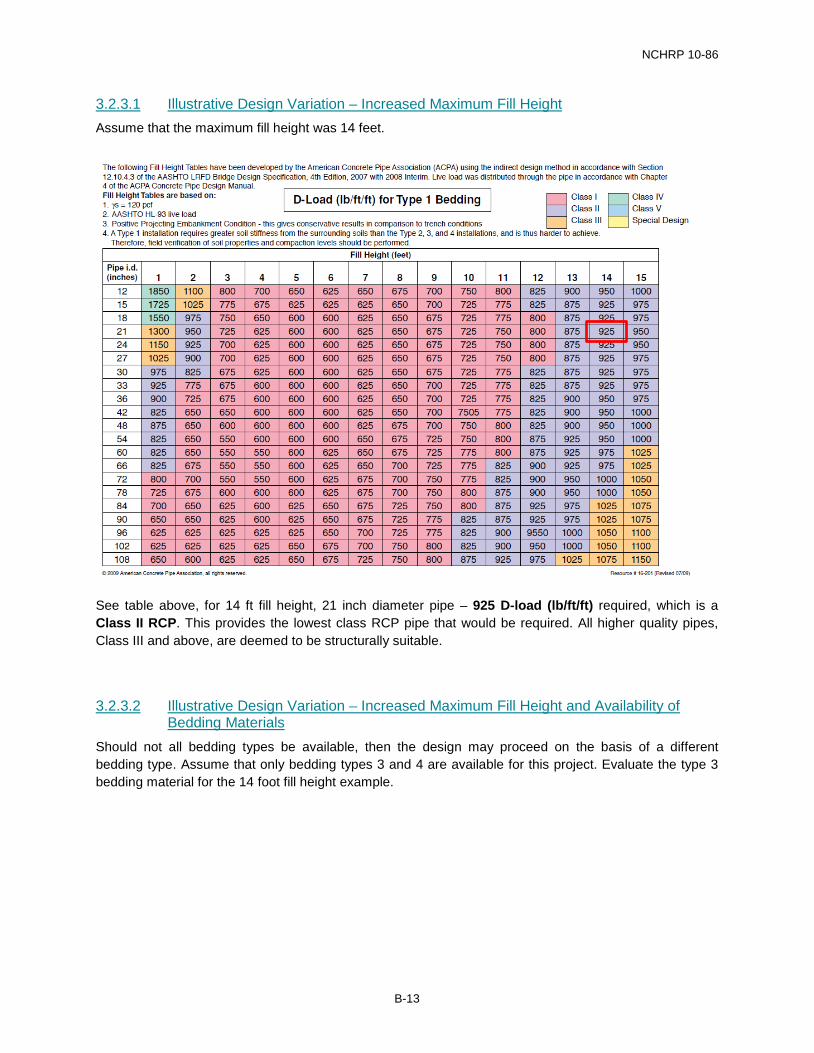
3.2.3.1 Illustrative Design Variation – Increased Maximum Fill Height Assume that the maximum fill height was 14 feet.
See table above, for 14 ft fill height, 21 inch diameter pipe – 925 D-load (lb/ft/ft) required, which is a Class II RCP. This provides the lowest class RCP pipe that would be required. All higher quality pipes, Class III and above, are deemed to be structurally suitable.
3.2.3.2 Illustrative Design Variation – Increased Maximum Fill Height and Availability of Bedding Materials
Should not all bedding types be available, then the design may proceed on the basis of a different bedding type. Assume that only bedding types 3 and 4 are available for this project. Evaluate the type 3 bedding material for the 14 foot fill height example.
B-13

NCHRP 10-86
See table above, for 14 ft fill height, 21 inch diameter pipe – 1425 D-load (lb/ft/ft) is required, which is a Class IV RCP. This provides the lowest class RCP pipe that would be required. All higher quality pipes, Class V and special design are deemed to be structurally suitable.
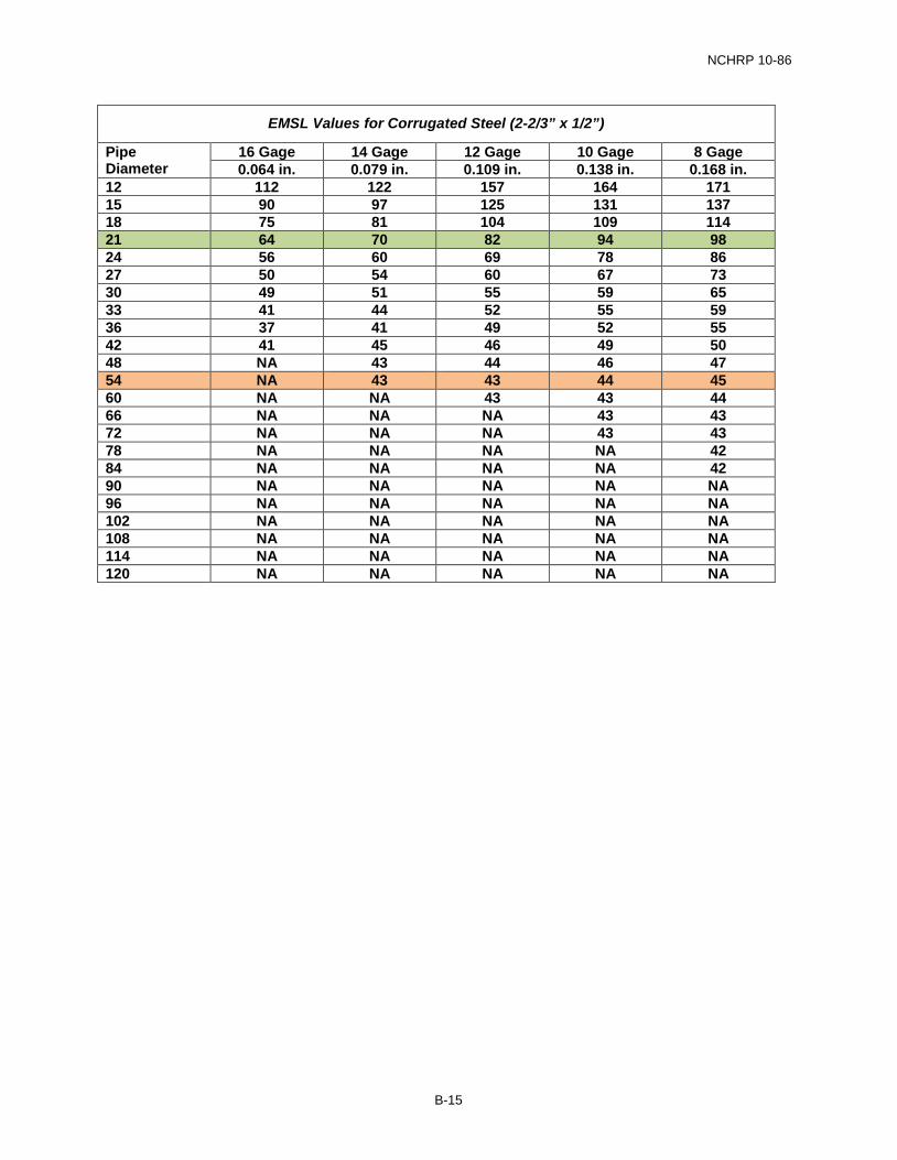
3.2.4 CMP Structural Evaluation CMP must be evaluated separately. Design tables, supplied by the metal pipe industry, have been used in this example to determine the maximum fill height for different corrugation profiles, gage thicknesses and pipe diameters. Alternatively, agency-specific fill height tables could be used.
To streamline evaluation, evaluate the highest gage (thinnest) section first, if that gage thickness has adequate structural capacity, then thicker gages are deemed structurally suitable.
The baseline example is highlighted
The illustrative design variation is highlighted
B-14
NCHRP 10-86
EMSL Values for Corrugated Steel (2-2/3” x 1/2”)
Pipe Diameter
16 Gage 14 Gage 12 Gage 10 Gage 8 Gage 0.064 in. 0.079 in. 0.109 in. 0.138 in. 0.168 in.
12 112 122 157 164 171 15 90 97 125 131 137 18 75 81 104 109 114 21 64 70 82 94 98 24 56 60 69 78 86 27 50 54 60 67 73 30 49 51 55 59 65 33 41 44 52 55 59 36 37 41 49 52 55 42 41 45 46 49 50 48 NA 43 44 46 47 54 NA 43 43 44 45 60 NA NA 43 43 44 66 NA NA NA 43 43 72 NA NA NA 43 43 78 NA NA NA NA 42 84 NA NA NA NA 42 90 NA NA NA NA NA 96 NA NA NA NA NA 102 NA NA NA NA NA 108 NA NA NA NA NA 114 NA NA NA NA NA 120 NA NA NA NA NA
B-15
NCHRP 10-86
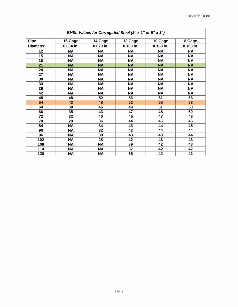
EMSL Values for Corrugated Steel (3” x 1” or 5” x 1”)
Pipe Diameter
16 Gage 14 Gage 12 Gage 10 Gage 8 Gage 0.064 in. 0.079 in. 0.109 in. 0.138 in. 0.168 in.
12 NA NA NA NA NA 15 NA NA NA NA NA 18 NA NA NA NA NA 21 NA NA NA NA NA 24 NA NA NA NA NA 27 NA NA NA NA NA 30 NA NA NA NA NA 33 NA NA NA NA NA 36 NA NA NA NA NA 42 NA NA NA NA NA 48 48 52 56 61 66 54 43 48 52 55 58 60 38 46 49 51 53 66 35 43 47 48 50 72 32 40 45 47 48 78 29 36 44 45 46 84 NA 34 43 44 45 90 NA 32 43 44 44 96 NA 30 43 43 44 102 NA 28 42 43 43 108 NA NA 39 42 43 114 NA NA 37 42 42 120 NA NA 35 42 42
B-16
NCHRP 10-86
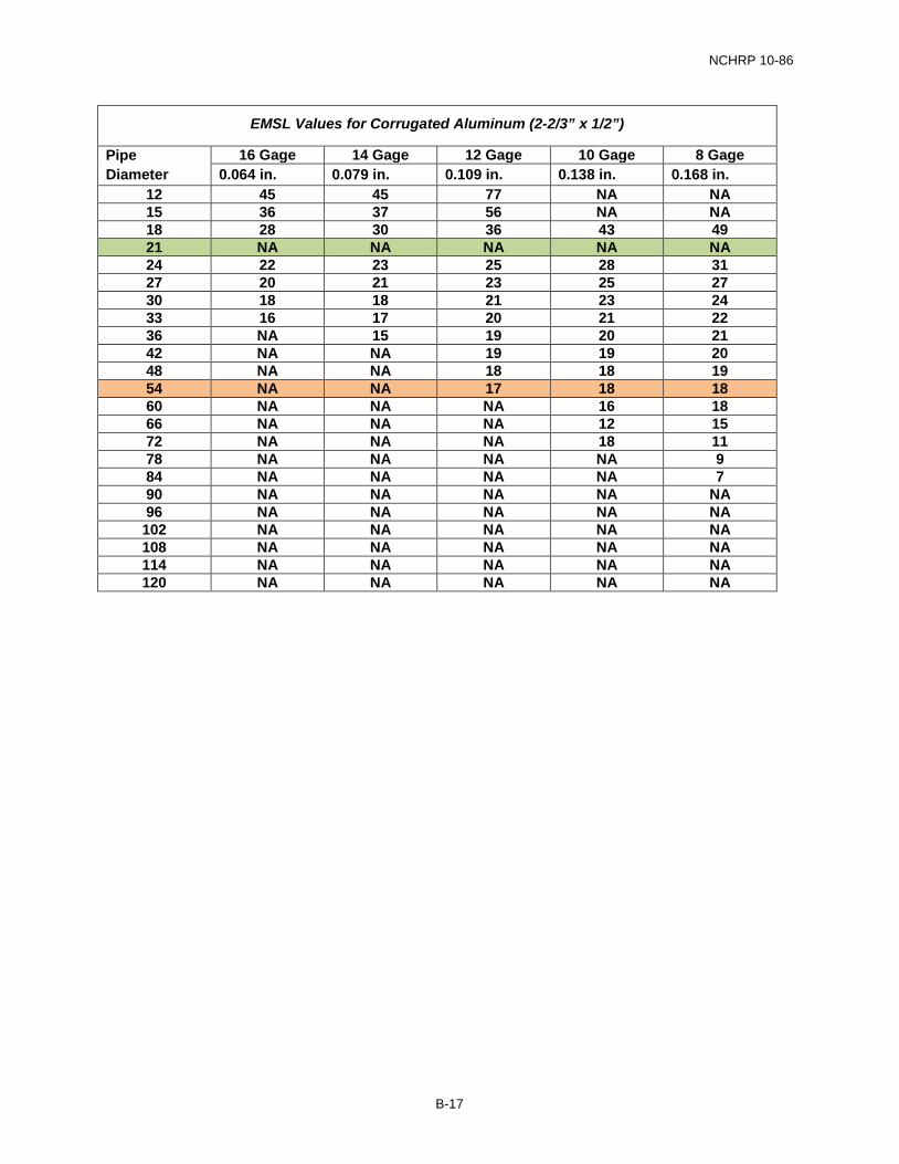
EMSL Values for Corrugated Aluminum (2-2/3” x 1/2”)
Pipe Diameter
16 Gage 14 Gage 12 Gage 10 Gage 8 Gage 0.064 in. 0.079 in. 0.109 in. 0.138 in. 0.168 in.
12 45 45 77 NA NA 15 36 37 56 NA NA 18 28 30 36 43 49 21 NA NA NA NA NA 24 22 23 25 28 31 27 20 21 23 25 27 30 18 18 21 23 24 33 16 17 20 21 22 36 NA 15 19 20 21 42 NA NA 19 19 20 48 NA NA 18 18 19 54 NA NA 17 18 18 60 NA NA NA 16 18 66 NA NA NA 12 15 72 NA NA NA 18 11 78 NA NA NA NA 9 84 NA NA NA NA 7 90 NA NA NA NA NA 96 NA NA NA NA NA 102 NA NA NA NA NA 108 NA NA NA NA NA 114 NA NA NA NA NA 120 NA NA NA NA NA
B-17
NCHRP 10-86
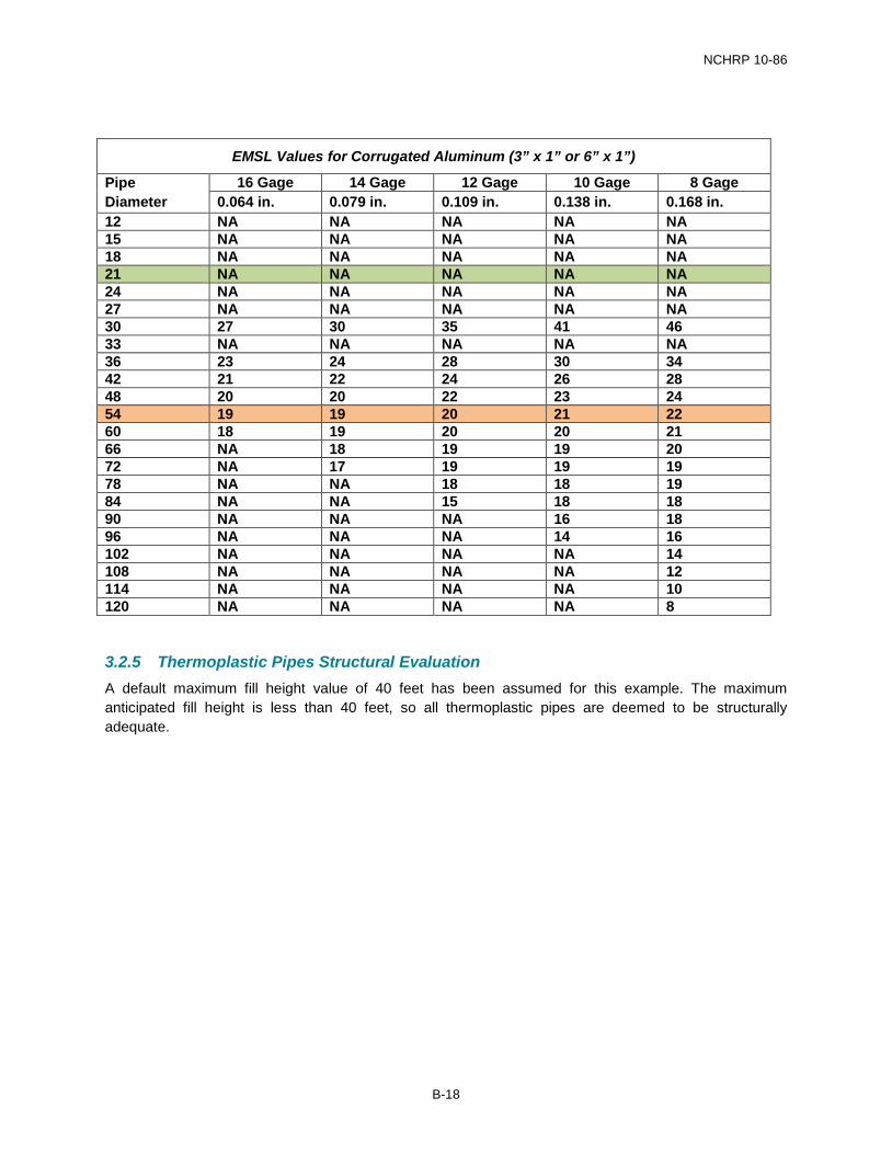
EMSL Values for Corrugated Aluminum (3” x 1” or 6” x 1”)
Pipe Diameter
16 Gage 14 Gage 12 Gage 10 Gage 8 Gage 0.064 in. 0.079 in. 0.109 in. 0.138 in. 0.168 in.
12 NA NA NA NA NA 15 NA NA NA NA NA 18 NA NA NA NA NA 21 NA NA NA NA NA 24 NA NA NA NA NA 27 NA NA NA NA NA 30 27 30 35 41 46 33 NA NA NA NA NA 36 23 24 28 30 34 42 21 22 24 26 28 48 20 20 22 23 24 54 19 19 20 21 22 60 18 19 20 20 21 66 NA 18 19 19 20 72 NA 17 19 19 19 78 NA NA 18 18 19 84 NA NA 15 18 18 90 NA NA NA 16 18 96 NA NA NA 14 16 102 NA NA NA NA 14 108 NA NA NA NA 12 114 NA NA NA NA 10 120 NA NA NA NA 8
3.2.5 Thermoplastic Pipes Structural Evaluation A default maximum fill height value of 40 feet has been assumed for this example. The maximum anticipated fill height is less than 40 feet, so all thermoplastic pipes are deemed to be structurally adequate.
B-18
NCHRP 10-86
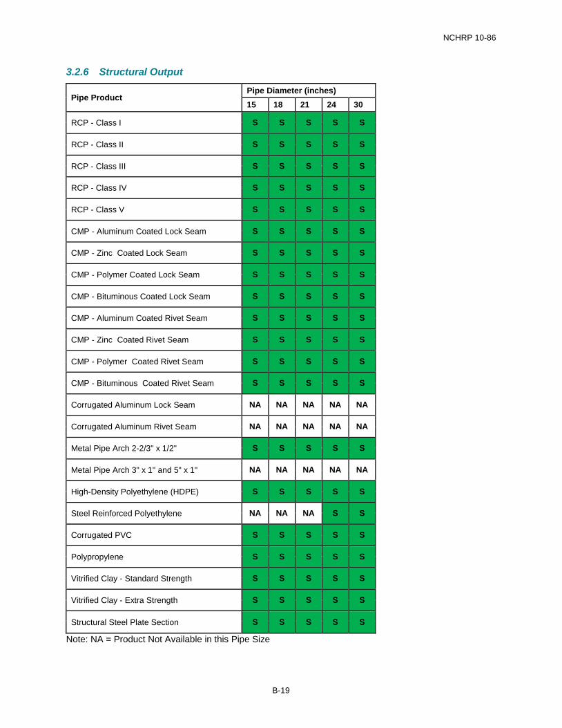
3.2.6 Structural Output
Pipe Product Pipe Diameter (inches) 15 18 21 24 30
RCP - Class I S S S S S
RCP - Class II S S S S S
RCP - Class III S S S S S
RCP - Class IV S S S S S
RCP - Class V S S S S S
CMP - Aluminum Coated Lock Seam S S S S S
CMP - Zinc Coated Lock Seam S S S S S
CMP - Polymer Coated Lock Seam S S S S S
CMP - Bituminous Coated Lock Seam S S S S S
CMP - Aluminum Coated Rivet Seam S S S S S
CMP - Zinc Coated Rivet Seam S S S S S
CMP - Polymer Coated Rivet Seam S S S S S
CMP - Bituminous Coated Rivet Seam S S S S S
Corrugated Aluminum Lock Seam NA NA NA NA NA
Corrugated Aluminum Rivet Seam NA NA NA NA NA
Metal Pipe Arch 2-2/3" x 1/2" S S S S S
Metal Pipe Arch 3" x 1" and 5" x 1" NA NA NA NA NA
High-Density Polyethylene (HDPE) S S S S S
Steel Reinforced Polyethylene NA NA NA S S
Corrugated PVC S S S S S
Polypropylene S S S S S
Vitrified Clay - Standard Strength S S S S S
Vitrified Clay - Extra Strength S S S S S
Structural Steel Plate Section S S S S S
Note: NA = Product Not Available in this Pipe Size
B-19
NCHRP 10-86
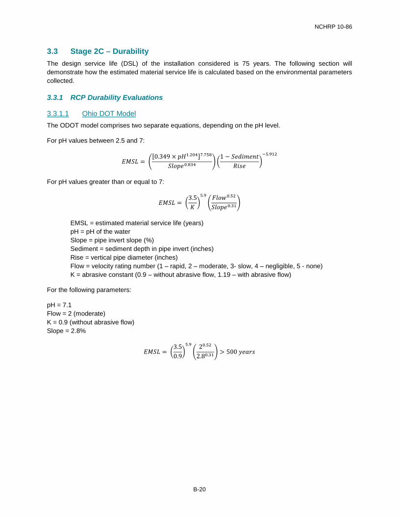
3.3 Stage 2C – Durability The design service life (DSL) of the installation considered is 75 years. The following section will demonstrate how the estimated material service life is calculated based on the environmental parameters collected.
3.3.1 RCP Durability Evaluations
3.3.1.1 Ohio DOT Model The ODOT model comprises two separate equations, depending on the pH level.
For pH values between 2.5 and 7:
𝐸𝐸𝐸𝐸𝐸𝐸𝐸𝐸 = �[0.349 × 𝑝𝑝𝑝𝑝1.204]7.758
𝐸𝐸𝑆𝑆𝑆𝑆𝑝𝑝𝑆𝑆0.834 � �1 − 𝐸𝐸𝑆𝑆𝑆𝑆𝑆𝑆𝑆𝑆𝑆𝑆𝑆𝑆𝑆𝑆
𝑅𝑅𝑆𝑆𝑅𝑅𝑆𝑆�−5.912
For pH values greater than or equal to 7:
𝐸𝐸𝐸𝐸𝐸𝐸𝐸𝐸 = �3.5𝐾𝐾�5.9
�𝐹𝐹𝑆𝑆𝑆𝑆𝐹𝐹0.52
𝐸𝐸𝑆𝑆𝑆𝑆𝑝𝑝𝑆𝑆0.31�
EMSL = estimated material service life (years) pH = pH of the water Slope = pipe invert slope (%) Sediment = sediment depth in pipe invert (inches) Rise = vertical pipe diameter (inches) Flow = velocity rating number (1 – rapid, 2 – moderate, 3- slow, 4 – negligible, 5 - none) K = abrasive constant (0.9 – without abrasive flow, 1.19 – with abrasive flow)
For the following parameters:
pH = 7.1 Flow = 2 (moderate) K = 0.9 (without abrasive flow) Slope = 2.8%
𝐸𝐸𝐸𝐸𝐸𝐸𝐸𝐸 = �3.50.9
�5.9
�20.52
2.80.31� > 500 𝑦𝑦𝑆𝑆𝑦𝑦𝑦𝑦𝑅𝑅
B-20
NCHRP 10-86
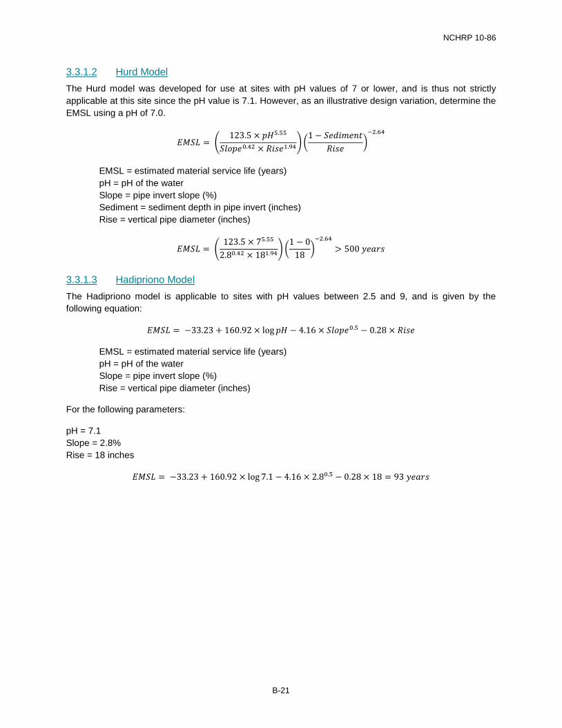
3.3.1.2 Hurd Model The Hurd model was developed for use at sites with pH values of 7 or lower, and is thus not strictly applicable at this site since the pH value is 7.1. However, as an illustrative design variation, determine the EMSL using a pH of 7.0.
𝐸𝐸𝐸𝐸𝐸𝐸𝐸𝐸 = �123.5 × 𝑝𝑝𝑝𝑝5.55
𝐸𝐸𝑆𝑆𝑆𝑆𝑝𝑝𝑆𝑆0.42 × 𝑅𝑅𝑆𝑆𝑅𝑅𝑆𝑆1.94� �1 − 𝐸𝐸𝑆𝑆𝑆𝑆𝑆𝑆𝑆𝑆𝑆𝑆𝑆𝑆𝑆𝑆
𝑅𝑅𝑆𝑆𝑅𝑅𝑆𝑆�−2.64
EMSL = estimated material service life (years) pH = pH of the water Slope = pipe invert slope (%) Sediment = sediment depth in pipe invert (inches) Rise = vertical pipe diameter (inches)
𝐸𝐸𝐸𝐸𝐸𝐸𝐸𝐸 = �123.5 × 75.55
2.80.42 × 181.94� �1 − 0
18�−2.64
> 500 𝑦𝑦𝑆𝑆𝑦𝑦𝑦𝑦𝑅𝑅
3.3.1.3 Hadipriono Model The Hadipriono model is applicable to sites with pH values between 2.5 and 9, and is given by the following equation:
𝐸𝐸𝐸𝐸𝐸𝐸𝐸𝐸 = −33.23 + 160.92 × log 𝑝𝑝𝑝𝑝 − 4.16 × 𝐸𝐸𝑆𝑆𝑆𝑆𝑝𝑝𝑆𝑆0.5 − 0.28 × 𝑅𝑅𝑆𝑆𝑅𝑅𝑆𝑆
EMSL = estimated material service life (years) pH = pH of the water Slope = pipe invert slope (%) Rise = vertical pipe diameter (inches)
For the following parameters:
pH = 7.1 Slope = 2.8% Rise = 18 inches
𝐸𝐸𝐸𝐸𝐸𝐸𝐸𝐸 = −33.23 + 160.92 × log 7.1 − 4.16 × 2.80.5 − 0.28 × 18 = 93 𝑦𝑦𝑆𝑆𝑦𝑦𝑦𝑦𝑅𝑅
B-21
NCHRP 10-86
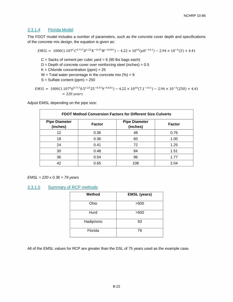
3.3.1.4 Florida Model The FDOT model includes a number of parameters, such as the concrete cover depth and specifications of the concrete mix design, the equation is given as:
𝐸𝐸𝐸𝐸𝐸𝐸𝐸𝐸 = 1000(1.107𝐶𝐶𝐶𝐶0.717𝐷𝐷1.22𝐾𝐾−0.37𝑊𝑊−0.631) − 4.22 × 10¹⁰(𝑝𝑝𝑝𝑝−14.1) − 2.94 × 10⁻³(𝐸𝐸) + 4.41
C = Sacks of cement per cubic yard = 6 (90 lbs bags each) D = Depth of concrete cover over reinforcing steel (inches) = 0.5 K = Chloride concentration (ppm) = 25 W = Total water percentage in the concrete mix (%) = 9 S = Sulfate content (ppm) = 250
𝐸𝐸𝐸𝐸𝐸𝐸𝐸𝐸 = 1000(1.107660.7170.51.2225−0.379−0.631) − 4.22 × 10¹⁰(7.1−14.1) − 2.94 × 10⁻³(250) + 4.41= 220 𝑦𝑦𝑆𝑆𝑦𝑦𝑦𝑦𝑅𝑅
Adjust EMSL depending on the pipe size:
FDOT Method Conversion Factors for Different Size Culverts
Pipe Diameter (inches) Factor Pipe Diameter
(inches) Factor
12 0.36 48 0.76 18 0.36 60 1.00 24 0.41 72 1.25 30 0.48 84 1.51 36 0.54 96 1.77 42 0.65 108 2.04
EMSL = 220 x 0.36 = 79 years
3.3.1.5 Summary of RCP methods Method EMSL (years)
Ohio >500
Hurd >500
Hadipriono 93
Florida 79
All of the EMSL values for RCP are greater than the DSL of 75 years used as the example case.
B-22
NCHRP 10-86
3.3.2 Galvanized Steel Durability Evaluations
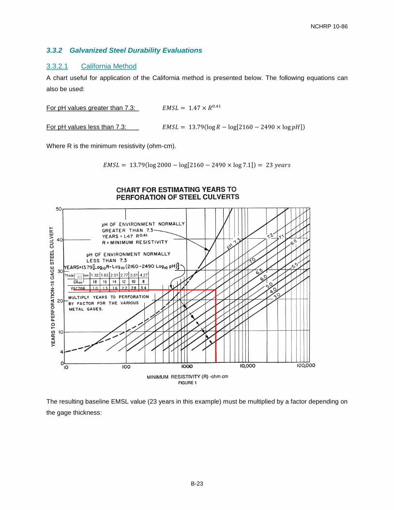
3.3.2.1 California Method A chart useful for application of the California method is presented below. The following equations can
also be used:
For pH values greater than 7.3: 𝐸𝐸𝐸𝐸𝐸𝐸𝐸𝐸 = 1.47 × 𝑅𝑅0.41
For pH values less than 7.3: 𝐸𝐸𝐸𝐸𝐸𝐸𝐸𝐸 = 13.79(log𝑅𝑅 − log[2160 − 2490 × log 𝑝𝑝𝑝𝑝])
Where R is the minimum resistivity (ohm-cm).
𝐸𝐸𝐸𝐸𝐸𝐸𝐸𝐸 = 13.79(log 2000 − log[2160 − 2490 × log 7.1]) = 23 𝑦𝑦𝑆𝑆𝑦𝑦𝑦𝑦𝑅𝑅
The resulting baseline EMSL value (23 years in this example) must be multiplied by a factor depending on
the gage thickness:
B-23
NCHRP 10-86
California Method Example Durability Results Gage 18 16 14 12 10 8 Factor 1 1.3 1.6 2.2 2.8 3.4 Calculated EMSL 23 29 36 50 64 78
EMSL > DSL No No No No No Yes
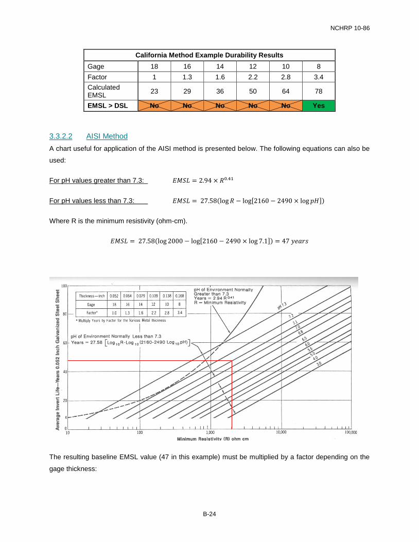
3.3.2.2 AISI Method A chart useful for application of the AISI method is presented below. The following equations can also be
used:
For pH values greater than 7.3: 𝐸𝐸𝐸𝐸𝐸𝐸𝐸𝐸 = 2.94 × 𝑅𝑅0.41
For pH values less than 7.3: 𝐸𝐸𝐸𝐸𝐸𝐸𝐸𝐸 = 27.58(log𝑅𝑅 − log[2160 − 2490 × log 𝑝𝑝𝑝𝑝])
Where R is the minimum resistivity (ohm-cm).
𝐸𝐸𝐸𝐸𝐸𝐸𝐸𝐸 = 27.58(log 2000 − log[2160 − 2490 × log 7.1]) = 47 𝑦𝑦𝑆𝑆𝑦𝑦𝑦𝑦𝑅𝑅
The resulting baseline EMSL value (47 in this example) must be multiplied by a factor depending on the
gage thickness:
B-24
NCHRP 10-86
AISI Method Example Durability Results Gage 18 16 14 12 10 8 Factor 1 1.3 1.6 2.2 2.8 3.4 Calculated EMSL 47 61 75 103 131 159
EMSL > DSL No No Yes Yes Yes Yes
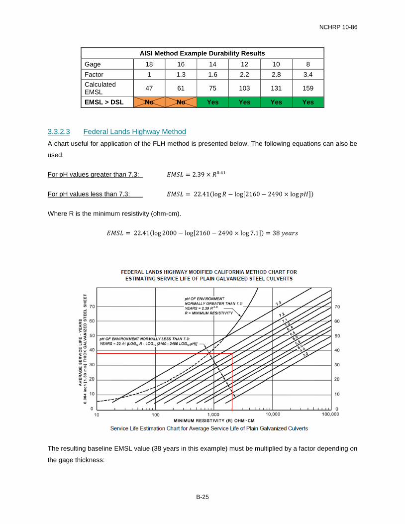
3.3.2.3 Federal Lands Highway Method A chart useful for application of the FLH method is presented below. The following equations can also be
used:
For pH values greater than 7.3: 𝐸𝐸𝐸𝐸𝐸𝐸𝐸𝐸 = 2.39 × 𝑅𝑅0.41
For pH values less than 7.3: 𝐸𝐸𝐸𝐸𝐸𝐸𝐸𝐸 = 22.41(log𝑅𝑅 − log[2160 − 2490 × log 𝑝𝑝𝑝𝑝])
Where R is the minimum resistivity (ohm-cm).
𝐸𝐸𝐸𝐸𝐸𝐸𝐸𝐸 = 22.41(log 2000 − log[2160 − 2490 × log 7.1]) = 38 𝑦𝑦𝑆𝑆𝑦𝑦𝑦𝑦𝑅𝑅
The resulting baseline EMSL value (38 years in this example) must be multiplied by a factor depending on
the gage thickness:
B-25
NCHRP 10-86
Federal Lands Highway Method Example Durability Results Gage 18 16 14 12 10 8 Factor 0.8 1 1.2 1.7 2.2 2.6 Calculated EMSL -- 38 45 64 83 98
EMSL > DSL No No No No Yes Yes
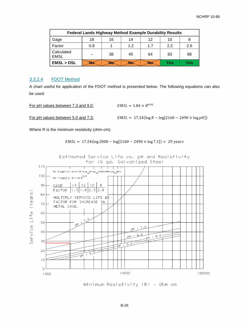
3.3.2.4 FDOT Method A chart useful for application of the FDOT method is presented below. The following equations can also
be used:
For pH values between 7.3 and 9.0: 𝐸𝐸𝐸𝐸𝐸𝐸𝐸𝐸 = 1.84 × 𝑅𝑅0.41
For pH values between 5.0 and 7.3: 𝐸𝐸𝐸𝐸𝐸𝐸𝐸𝐸 = 17.24(log𝑅𝑅 − log[2160 − 2490 × log 𝑝𝑝𝑝𝑝])
Where R is the minimum resistivity (ohm-cm).
𝐸𝐸𝐸𝐸𝐸𝐸𝐸𝐸 = 17.24(log 2000 − log[2160 − 2490 × log 7.1]) = 29 𝑦𝑦𝑆𝑆𝑦𝑦𝑦𝑦𝑅𝑅
B-26
NCHRP 10-86
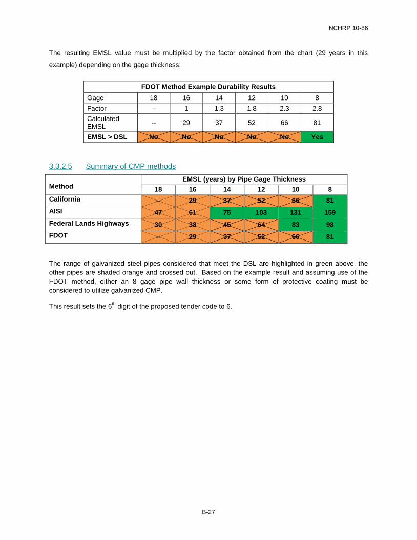
The resulting EMSL value must be multiplied by the factor obtained from the chart (29 years in this
example) depending on the gage thickness:
FDOT Method Example Durability Results Gage 18 16 14 12 10 8 Factor -- 1 1.3 1.8 2.3 2.8 Calculated EMSL -- 29 37 52 66 81
EMSL > DSL No No No No No Yes
3.3.2.5 Summary of CMP methods
Method EMSL (years) by Pipe Gage Thickness
18 16 14 12 10 8 California -- 29 37 52 66 81 AISI 47 61 75 103 131 159 Federal Lands Highways 30 38 45 64 83 98 FDOT -- 29 37 52 66 81
The range of galvanized steel pipes considered that meet the DSL are highlighted in green above, the other pipes are shaded orange and crossed out. Based on the example result and assuming use of the FDOT method, either an 8 gage pipe wall thickness or some form of protective coating must be considered to utilize galvanized CMP.
This result sets the 6th digit of the proposed tender code to 6.
B-27

NCHRP 10-86
3.3.2.6 Protective coatings for metal pipes
Note: For this example, the FHWA abrasion level is assumed to be the same as the Caltrans abrasion level (flow on CMP = 6.5 ft/s).
The coating materials that would provide sufficient protection to meet the DSL are highlighted in the red box, assuming abrasion level 2 is applicable. Any of the galvanized steel pipes could be used with these coatings to achieve the DSL as they achieve EMSL values greater than the required DSL of 75 when added to the baseline galvanized EMSL of 29 years (assuming use of the FDOT method).
16 gage and thicker galvanized pipes are suitable from a durability perspective for the example case, setting the 7th digit of the proposed tender code to 2.
The use of coatings is not explicitly covered in the summary matrices shown in this example. A comprehensive list of all pipe system option would include each of these lining types as separate pipe system options.
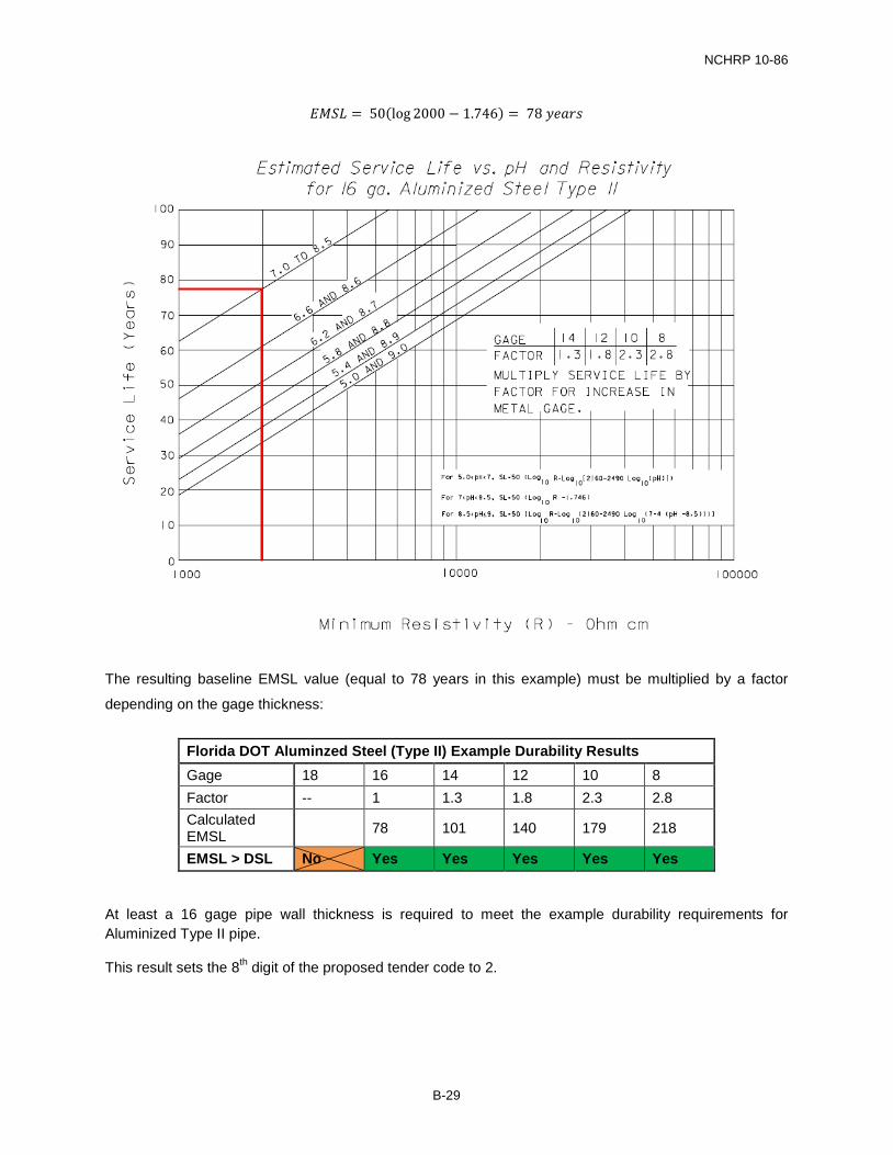
3.3.3 Aluminized Steel Pipe (Type II) Durability Evaluations The FDOT method for estimating material service life of aluminized (type II) steel can be applied using a
chart presented below. The following equations can also be used:
For pH between 5.0 and 7.0: 𝐸𝐸𝐸𝐸𝐸𝐸𝐸𝐸 = 50(log𝑅𝑅 − log[2160 − 2490 × log 𝑝𝑝𝑝𝑝])
For pH between 7.0 and 8.5: 𝐸𝐸𝐸𝐸𝐸𝐸𝐸𝐸 = 50(log𝑅𝑅 − 1.746)
For pH between 8.5 and 9.0: 𝐸𝐸𝐸𝐸𝐸𝐸𝐸𝐸 = 50�log𝑅𝑅 − log�2160 − 2490 × log�7 − 4(𝑝𝑝𝑝𝑝 − 8.5)���
Where R is the minimum resistivity (ohm-cm).
B-28
NCHRP 10-86
𝐸𝐸𝐸𝐸𝐸𝐸𝐸𝐸 = 50(log 2000 − 1.746) = 78 𝑦𝑦𝑆𝑆𝑦𝑦𝑦𝑦𝑅𝑅
The resulting baseline EMSL value (equal to 78 years in this example) must be multiplied by a factor
depending on the gage thickness:
Florida DOT Aluminzed Steel (Type II) Example Durability Results Gage 18 16 14 12 10 8 Factor -- 1 1.3 1.8 2.3 2.8 Calculated EMSL 78 101 140 179 218
EMSL > DSL No Yes Yes Yes Yes Yes
At least a 16 gage pipe wall thickness is required to meet the example durability requirements for Aluminized Type II pipe.
This result sets the 8th digit of the proposed tender code to 2.
B-29
NCHRP 10-86
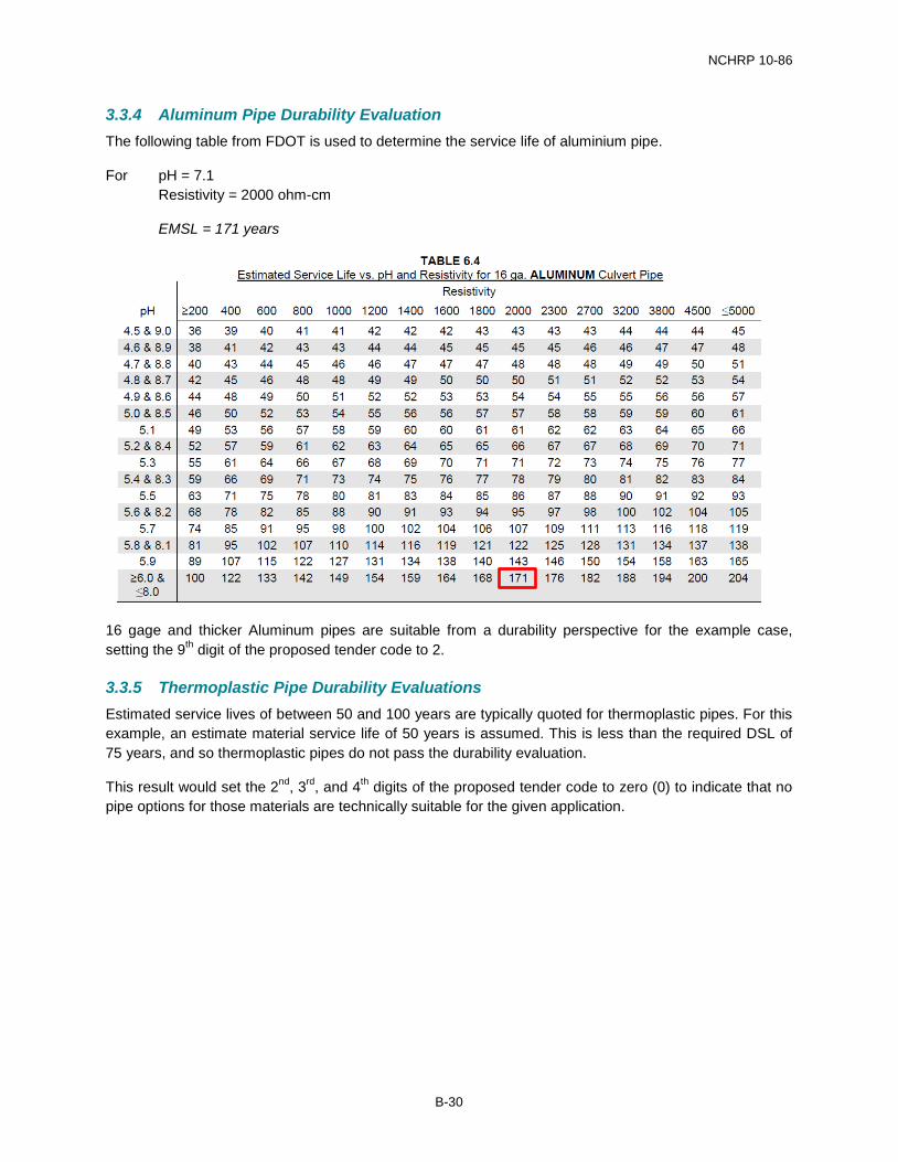
3.3.4 Aluminum Pipe Durability Evaluation The following table from FDOT is used to determine the service life of aluminium pipe.
For pH = 7.1 Resistivity = 2000 ohm-cm
EMSL = 171 years
16 gage and thicker Aluminum pipes are suitable from a durability perspective for the example case, setting the 9th digit of the proposed tender code to 2.
3.3.5 Thermoplastic Pipe Durability Evaluations Estimated service lives of between 50 and 100 years are typically quoted for thermoplastic pipes. For this example, an estimate material service life of 50 years is assumed. This is less than the required DSL of 75 years, and so thermoplastic pipes do not pass the durability evaluation.
This result would set the 2nd, 3rd, and 4th digits of the proposed tender code to zero (0) to indicate that no pipe options for those materials are technically suitable for the given application.
B-30
NCHRP 10-86
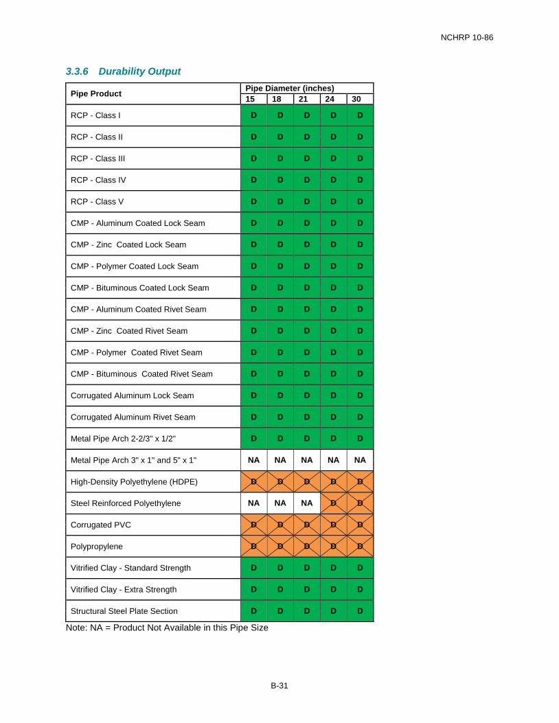
3.3.6 Durability Output
Pipe Product Pipe Diameter (inches) 15 18 21 24 30
RCP - Class I D D D D D
RCP - Class II D D D D D
RCP - Class III D D D D D
RCP - Class IV D D D D D
RCP - Class V D D D D D
CMP - Aluminum Coated Lock Seam D D D D D
CMP - Zinc Coated Lock Seam D D D D D
CMP - Polymer Coated Lock Seam D D D D D
CMP - Bituminous Coated Lock Seam D D D D D
CMP - Aluminum Coated Rivet Seam D D D D D
CMP - Zinc Coated Rivet Seam D D D D D
CMP - Polymer Coated Rivet Seam D D D D D
CMP - Bituminous Coated Rivet Seam D D D D D
Corrugated Aluminum Lock Seam D D D D D
Corrugated Aluminum Rivet Seam D D D D D
Metal Pipe Arch 2-2/3" x 1/2" D D D D D
Metal Pipe Arch 3" x 1" and 5" x 1" NA NA NA NA NA
High-Density Polyethylene (HDPE) D D D D D
Steel Reinforced Polyethylene NA NA NA D D
Corrugated PVC D D D D D
Polypropylene D D D D D
Vitrified Clay - Standard Strength D D D D D
Vitrified Clay - Extra Strength D D D D D
Structural Steel Plate Section D D D D D
Note: NA = Product Not Available in this Pipe Size
B-31
NCHRP 10-86
4.0 PHASE 3 – FINAL DESIGN CHECK AND POLICY APPLICATION
4.1 Stage 3A – Final Design Check None of the common supplemental design checks were flagged in Phase 1 for further consideration during Phase 3.
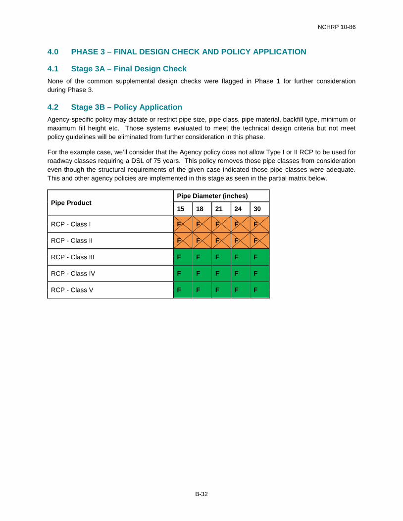
4.2 Stage 3B – Policy Application Agency-specific policy may dictate or restrict pipe size, pipe class, pipe material, backfill type, minimum or maximum fill height etc. Those systems evaluated to meet the technical design criteria but not meet policy guidelines will be eliminated from further consideration in this phase.
For the example case, we’ll consider that the Agency policy does not allow Type I or II RCP to be used for roadway classes requiring a DSL of 75 years. This policy removes those pipe classes from consideration even though the structural requirements of the given case indicated those pipe classes were adequate. This and other agency policies are implemented in this stage as seen in the partial matrix below.
Pipe Product Pipe Diameter (inches)
15 18 21 24 30
RCP - Class I F F F F F
RCP - Class II F F F F F
RCP - Class III F F F F F
RCP - Class IV F F F F F
RCP - Class V F F F F F
B-32

NCHRP 10-86
5.0 PHASE 4 – RESULTS AND BIDDING
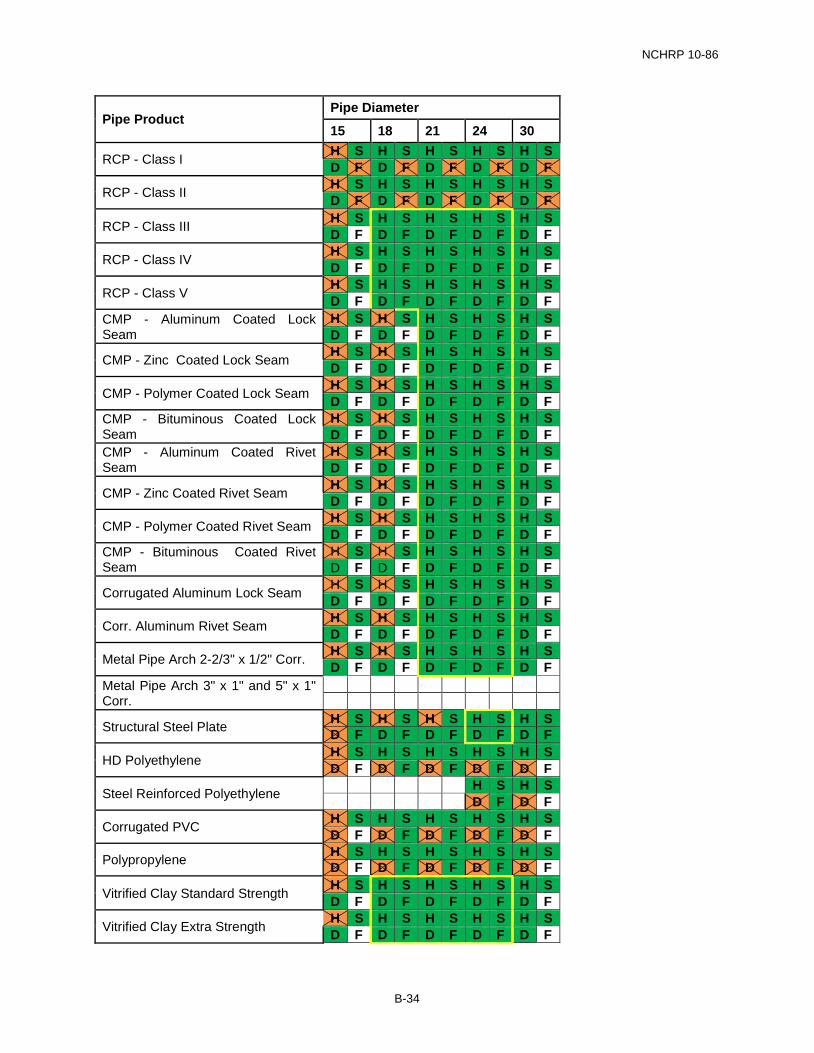
5.1 Stage 4A – Summary and Reporting of Evaluation Results The three matrices are now combined into a single matrix presenting the results of the analysis.
Cells circled in yellow lines indicate the pipe systems that have passed the technical and policy design evaluations.
B-33
NCHRP 10-86
Pipe Product Pipe Diameter
15 18 21 24 30
RCP - Class I H S H S H S H S H S D F D F D F D F D F
RCP - Class II H S H S H S H S H S D F D F D F D F D F
RCP - Class III H S H S H S H S H S D F D F D F D F D F
RCP - Class IV H S H S H S H S H S D F D F D F D F D F
RCP - Class V H S H S H S H S H S D F D F D F D F D F
CMP - Aluminum Coated Lock Seam
H S H S H S H S H S D F D F D F D F D F
CMP - Zinc Coated Lock Seam H S H S H S H S H S D F D F D F D F D F
CMP - Polymer Coated Lock Seam H S H S H S H S H S D F D F D F D F D F
CMP - Bituminous Coated Lock Seam
H S H S H S H S H S D F D F D F D F D F
CMP - Aluminum Coated Rivet Seam
H S H S H S H S H S D F D F D F D F D F
CMP - Zinc Coated Rivet Seam H S H S H S H S H S D F D F D F D F D F
CMP - Polymer Coated Rivet Seam H S H S H S H S H S D F D F D F D F D F
CMP - Bituminous Coated Rivet Seam
H S H S H S H S H S D F D F D F D F D F
Corrugated Aluminum Lock Seam H S H S H S H S H S D F D F D F D F D F
Corr. Aluminum Rivet Seam H S H S H S H S H S D F D F D F D F D F
Metal Pipe Arch 2-2/3" x 1/2" Corr. H S H S H S H S H S D F D F D F D F D F
Metal Pipe Arch 3" x 1" and 5" x 1" Corr.
Structural Steel Plate H S H S H S H S H S D F D F D F D F D F
HD Polyethylene H S H S H S H S H S D F D F D F D F D F
Steel Reinforced Polyethylene H S H S D F D F
Corrugated PVC H S H S H S H S H S D F D F D F D F D F
Polypropylene H S H S H S H S H S D F D F D F D F D F
Vitrified Clay Standard Strength H S H S H S H S H S D F D F D F D F D F
Vitrified Clay Extra Strength H S H S H S H S H S D F D F D F D F D F
B-34
NCHRP 10-86
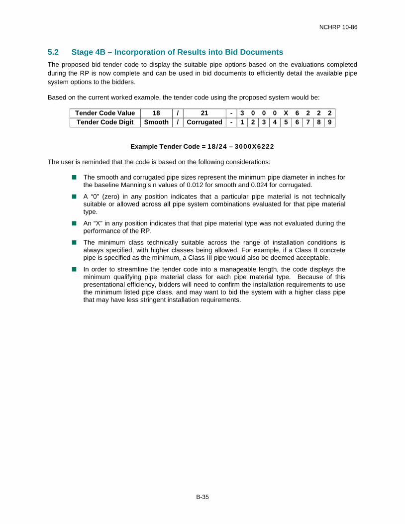
5.2 Stage 4B – Incorporation of Results into Bid Documents The proposed bid tender code to display the suitable pipe options based on the evaluations completed during the RP is now complete and can be used in bid documents to efficiently detail the available pipe system options to the bidders.
Based on the current worked example, the tender code using the proposed system would be:
Tender Code Value 18 / 21 - 3 0 0 0 X 6 2 2 2 Tender Code Digit Smooth / Corrugated - 1 2 3 4 5 6 7 8 9
Example Tender Code = 18/24 – 3000X6222
The user is reminded that the code is based on the following considerations:
The smooth and corrugated pipe sizes represent the minimum pipe diameter in inches for the baseline Manning’s n values of 0.012 for smooth and 0.024 for corrugated.
A “0” (zero) in any position indicates that a particular pipe material is not technically suitable or allowed across all pipe system combinations evaluated for that pipe material type.
An “X” in any position indicates that that pipe material type was not evaluated during the performance of the RP.
The minimum class technically suitable across the range of installation conditions is always specified, with higher classes being allowed. For example, if a Class II concrete pipe is specified as the minimum, a Class III pipe would also be deemed acceptable.
In order to streamline the tender code into a manageable length, the code displays the minimum qualifying pipe material class for each pipe material type. Because of this presentational efficiency, bidders will need to confirm the installation requirements to use the minimum listed pipe class, and may want to bid the system with a higher class pipe that may have less stringent installation requirements.
B-35