workhorse for rough machining operations · pdf fileworkhorse for rough machining operations !...
TRANSCRIPT

NEWShoulder milling cutter
Workhorse for rough machining operations !
Tungaloy Report No. 415-US

2
1
3
4
2
ø.750" ~ ø1.000"
ø1.000" ~ ø2.000"
ø2.000" ~ ø2.500"
6
5
4
3
2
1
0
.7502 3
490.004
.8 .4.3
ELD05R075U0075W021
Light machining
High
Low
Machine and work
rigidity
Heavy machining
Suitable for roughing operations on BT40 spindle taper machines
Optimum edge position prevents chatterHigh helix angle distributes and reduces the load for smoother cuttingBest solution for preventing chip recutting• Small inserts create small chips• Through tool air blast blows chips from the
cutting area
Proven insert from standard range• 4 cornered insert offers
higher operating profi t• Positive rake chipbreakers
MJ: for general purposeincluding exotic materialAJ: for machining of aluminum
Application range of roughing series
Comparison of metal removal rate
Met
al r
emov
al r
ate
Q (i
n3 /min
)
Competitor A
Improved by 33%!
Optimum cutter design allows high productivity with large depth of cut
Work material Tool diameter øDc (in)Effective number of cutting edge lineCutting speed Vc (sfm)Feed per edge line fz (ipt)Depth of cut ap (in)Width of cut ae (in)Machine
CompetitorCondition
Vertical M/C CAT40
1055

3
1
3
4
2
50
40
30
20
10
0
15
12
9
6
3
0
1.250
3 2330.0061.25.55
ELS11R125U0125W03
TLM11R200U0075A03
23 4
330.008
2 1.6
1.2 .8
Comparison of metal removal rate
Comparison of metal removal rate
Versatile cutters for various work materials
New solution for roughing operations on large machines
• Large core thickness increases body rigidity
Optimized angular positioning prevents chatter
Tangential insert with tough edge allows high feed machiningHighly rigid body, suitable for heavy machining
Air blast through tool to blow off chips
Cutters with high insert density delivers higher productivity
Air blast through tool blows off chips
Proven insert from standard range
Proven insert from standard range
• Suitable for roughing operation of various materials
• Tough cutting edge and low cutting force chipbreakersMJ: for general purposeMS: for stainless steel and exotic material machiningAJ: for machining of aluminum
• 4 cornered insert offers higher operating profi t
Met
al r
emov
al r
ate
Q (i
n3 /min
)M
etal
rem
oval
rat
eQ
(in3 /m
in)
Competitor A
Competitor A
Higher number of fl utes guarantees high productivity
Tough cutting edges provide stable machining even in heavy roughing operations
Work material Tool diameter øDc (in)Effective number of cutting edge lineCutting speed Vc (sfm)Feed per edge line fz (ipt)Depth of cut ap (in)Width of cut ae (in)Machine
Work material Tool diameter øDc (in)Effective number of cutting edge lineCutting speed Vc (sfm)Feed per edge line fz (ipt)Depth of cut ap (in)Width of cut ae (in)Machine
Competitor
Competitor
Condition
Condition
Vertical M/C CAT50
Vertical M/C CAT50
Improved by 40%!
Improved by 50%!
1055
1055
4
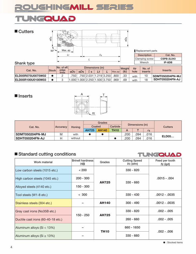
HB Vc (sfm)
< 200
AH725
330 - 820
.0015 - .004200 - 300330 - 660
150 - 300
< 300 330 - 430 .0012 - .0035
− AH140 300 - 490 .0012 - .0035
150 - 250 AH725330 - 820 .002 - .005
260 - 660 .002 - .005
−TH10
660 - 1650.002 - .006
− 330 - 660
øDc øDs rs Lf L Max.ap
ELD05R075U0075W02 � 2 .750 .750 2.031 1.219 3.250 .800 .33 10 SDMT050204PN-MJSDHT050204FN-AJELD05R100U0100W03 � 3 1.000 1.000 2.250 1.500 3.750 .969 .69 18
L
Lf Rs
øDc
øDs
ap90°
rε
TA
AH725 AH140 TH10 A T rεSDMT050204PN-MJ M � � .200 .094 .016
ELD05…SDHT050204FN-AJ H � .200 .094 .016
CSPB-2L043IP-6DB
� : Stocked items
Inserts
Cutters
Low carbon steels (1015 etc.)
High carbon steels (1045 etc.)
Alloyed steels (4140 etc.)
Tool steels (W1-8 etc.)
Stainless steels (304 etc.)
Gray cast irons (No35B etc.)
Ductile cast irons (60-40-18 etc.)
Aluminum alloys (Si < 13%)
Aluminum alloys (Si ≥ 13%)
Standard cutting conditions
Description Cat. No.
Shank typeWeight
(Ib)Air
holeNo. ofinserts
Clamping screwWrench
withwithout
withwith
Cat. No.
Cat. No.
GradesCoated Carbide
Dimensions (in)
Dimensions (in)Cutters
InsertsStock
Accuracy Honing
Brinell hardness Cutting Speed Feed per tooth Work material Grades
fz (ipt)
No. of eff. edge lines
Replacement parts

5
Corner radius rε (in) The dimension of modifying (in)
øDc øDb ød r Lf b a Max. ap
TLS11R200U0075A04 � 4 2.000 1.875 .750 .750 2.356 .197 .315 1.921 1.22 20 ASMT11T3..., ASGT11T3...
øDc øDs rs Lf L Max. ap
ELS11R100U0100W02 � 2 1.000 1.000 2.250 1.500 3.750 1.197 .67 6ASMT11T3…ASGT11T3…
ELS11R125U0125W03 � 3 1.250 1.250 2.250 2.250 4.500 1.535 1.24 12ELS11R150U0125W03 � 3 1.500 1.250 2.329 2.171 4.500 1.551 1.47 12
L
øDs
øDc
˚ Lf Rs
ap
TLS11R... ELS11R...CSPB-2.5
IP-8DCM10X40H -
AH725 AH120 AH130 AH140 T3130 T1115 DS1100 NS740 KS05F A B T rε
ASMT11T304PDPR-MJ
M
� � � � �
.457 .264 .146
.016
ELS11RTLS11R
ASMT11T308PDPR-MJ � � � � � .031ASMT11T312PDPR-MJ � � � .047ASMT11T316PDPR-MJ � � � � .063ASMT11T320PDPR-MJ � .079ASMT11T330PDPR-MJ � .118ASMT11T304PDPR-MS � � .016ASGT11T304PDFR-AJ
G� � .016
ASGT11T308PDFR-AJ � � .031
B
TAA
B
T
r r
A
B
T
r
.016 ~ .063
.079 ~ .118 .080
R
øDc
øDb
b
R
øda
apL f
90º
� : Stocked items
Inserts
Cutters
Description Cat. No.
withwithwithwithwithwithwithwithwith
No modifi cation required
When using inserts with corner radius rε ≥ .079", standard cutter bodies have to be modifi ed “R”.
• From 2nd row onwards, please use insert with rε = .016" or .031".
Cautionary point in modifying cutter bodies
Shank typeBore type
Bore type
Shank type
Fig.4Fig.4Fig.4Fig.4Fig.4Fig.4Fig.5Fig.6Fig.6
Weight(Ib)
Weight(Ib)
Airhole
Airhole
No. ofinserts
No. ofinserts
Cutter
Clamping screwWrench
Center bolt
Fig. 5 MSFig. 4 MJ Fig. 6 AJ
withwith
with
with
Cat. No.
Cat. No.
Cat. No.
GradesCoated CarbideCermet
Dimensions (in)
Dimensions (in)
Dimensions (in)Shape Cutters
Inserts
Inserts
Stock
Stock
Acc
urac
y
Ho
ning
No. of eff. edge lines
No. of eff. edge lines
Replacement parts

6
HB Vc (sfm) fz (ipt)
MJ MS AJ
< 200AH725
330 - 820.004 - .007 - -
T3130 .004 - .007 - -
200 - 300AH725
330 - 660.003 - .006 - -
T3130 .003 - .006 - -
150 - 300AH725
330 - 490.003 - .006 - -
T3130 .003 - .006 - -
- - AH130 330 - 490 - .003 - .006 -
150 - 250AH120
330 - 820.004 - .007 - -
T1115 .004 - .007 - -
150 - 250AH120
260 - 660.004 - .007 - -
T1115 .004 - .007 - -
- - DS1100 660 - 1650 - - .002 - .007
- - DS1100 330 - 660 - - .002 - .007
- - AH130 60 - 200 - .003 - .006 -
- - AH725 60 - 130 .003 - .005 - -
TLM11R200… TLM11R250…
CSTB-3.5L110
BT15S
H-TB
T-15T
SD06-A2 SD08-52øDc
øda
øDb
ap
L f
R
b
90º
AH725 T3130 AH140 AH120 T1115 A B T rε
LMMU110708PNER-MJ M � � � � � .413 .280 .461 .031
TLM11…LMMU110716PNER-MJ M � � � � � .413 .280 .453 .063LMMU110724PNER-MJ M � � � � � .413 .280 .445 .094LMMU110732PNER-MJ M � � � � � .413 .280 .437 .125
A
rε
BT
øDc øDb ød r Lf b a Max. ap
TLM11R200U0075A03 � 3 2.000 1.850 .750 .750 2.750 0.157 .315 2.323 1.85 21LMMU1107**
TLM11R250U0100A04 � 4 2.500 2.323 1.000 .750 3.250 0.197 .374 2.654 3.33 32
Standard cutting conditions
Replacement parts
Description Cat. No.
Cutters
Inserts
� : Stocked items
Bore type
Work materialBrinell
hardness Priority GradeCutting speed Feed per tooth:
First choiceFor wear resistance
First choiceFor wear resistance
First choiceFor wear resistance
First choiceFor wear resistance
First choiceFor wear resistance
Wre
nch
Applicable cutter Clamping screw
Torx bit
Grip Mono block type substitution wrench
Center bolt
Cat. No.Dimensions (in)
InsertsNo. of eff.
edge lines
Stock Air holeWeight(lb)
No. ofinserts
withwith
Stock Cat. No. Accuracy Honing Coated grades
Dimensions (in) Cutters
withwithwithwith
Low carbon steels (1010, 1015 etc.)High carbon steels and alloy steels (1045, 4140 etc.)
Tool steels (H13 etc.)
Stainless steels (304,316 etc.)
Gray cast irons (No.250B, No.300B etc.)Ductile cast irons (65-45-12, 80-55-06 etc.)
Aluminum alloys (Si < 13%)
Aluminum alloys (Si ≥ 13%)
Titanium alloys (Ti-6AI-4V etc)Nickel-based alloys(Inconel718 etc.)

7
HB Vc (sfm) fz (ipt)
< 200
AH725 330 - 820
.004 - .009AH140 260 - 590
T3130 330 - 820
200 - 300
AH725 330 - 660
.003 - .008AH140 260 - 490
T3130 330 - 660
150 - 300
AH725 330 - 660
.003 - .008AH140 260 - 490
T3130 330 - 660
< 300
AH725 330 - 490
.003 - .008AH140 260 - 390
T3130 330 - 490
- AH140 300 - 490 .003 - .008
150 - 250
AH120330 - 820 .004 - .010
T1115
AH120260 - 660 .004 - .010
T1115
- AH725 70 - 160 .002 - .006
ELD05R075U0075W02 (ø.75", z = 2) TLS11R200U0075A04 (ø.2", z = 4)ASMT11T308PDPR-MJ
AH725 AH725
330 490.003 .00710 26.2.4 1.575
.2
2.5
2.0
1.5
1.0
0.5
0
5
4
3
2
1
0
Standard cutting conditions
• From 2nd row onwards, please use insert with rε = .031"
Work materialBrinell
hardness Priority Grade Cutting speed Feed per tooth
First choice
Priority for impact resistance
Priority for wear resistance
First choice
Priority for impact resistance
Priority for wear resistance
First choice
Priority for impact resistance
Priority for wear resistance
First choice
Priority for impact resistance
Priority for wear resistance
First choice
First choice
Priority for wear resistance
First choice
Priority for wear resistance
First choice
Practical examplesCover of machine
Competitor Competitor
Machine part
Shoulder millingDry
Vertical M/C CAT50
Shoulder millingWet
Flexible machine BT40
Met
al r
emov
al r
ate
Q (i
n3 /m
in)
Mac
hini
ng t
ime
(min
)
TungRec can machine at a 30% higher table speed with no chatter, even when machining on machine tools and components with low rigidity levels.
Higher productivity achieved than with competitor solid end mills. Reduction of inventory with the reduction of regrinding costs.
Productivity 1.3 times!
Machining time
reduced 20%!
Low carbon steel4140
Cut
ting
co
nditi
ons
Work piece typeCutterInsertGrade
Work material
Cutting speed: Vc (sfm) Feed per tooth: fz (ipt) Feed speed: Vf (in/min) Depth of cut: ap (in) Width of cut: ae (in) Method of machining
Coolant
Machine
Results
.24 × 3 passes
SDMT050204PN-MJ
Low carbon steels (1010, 1015 etc.)
High carbon steels (1045, 1055 etc.)
Alloy steels (4140, 5120 etc.)
Tool steels (D-2, M3-1 etc.)
Stainless steels(304, 316 etc.)
Gray cast irons(No.250B etc.)
Ductile cast irons(65-45-12 etc.)
Super alloys (Inconel718, Ti-6AL-4V etc.)
1.57
5"
.4"

TLS11R200U0075A04 (ø2", z = 4) TLM11R200U0075A03 (ø2", z = 3)ASMT11T308PDPR-MJ LMMU110708PNER-MJ
AH725 AH120
100 490.003 .0082.3 22
1.65 1.6.080 .8
160140120100806040200
302520151050
1.6"
1.65
"
Power generator part Base of machine
Shoulder millingDry
Vertical M/C CAT50
Shoulder millingWet
Horizontal M/C CAT50
Met
al r
emov
al r
ate
Q (c
m3 /
min)
Mac
hini
ng t
ime
(min
)
Machining with large depth of cut with TungRec can drastically reduce machining time. Achieves stable tool life due to no chipping on cutting edges.
TecMill allows more stable machiningwithout chipping on the cutting edges, this improves productivity by 60%.
Inconel 718 No.250B
Cu
ttin
g c
on
dit
ion
sWork piece type
CutterInsertGrade
Work material
Cutting speed: Vc (sfm) Feed per tooth: fz (ipt) Feed speed: Vf (in/min) Depth of cut: ap (in) Width of cut: ae (in) Method of machining
Coolant
Machine
Results
Productivity 1.6 times!
CompetitorCompetitor
Machining time
reduced 60%!
Distributed by:
Jan. 2013 (TJ)
3726 N Ventura Drive, Arlington Heights, IL 60004, U.S.A.Phone: +1-888-554-8394 Fax: +1-888-554-8392
Tungaloy Canada432 Elgin St. Unit 3, Brantford, Ontario N3S 7P7, CanadaPhone: +1-519-758-5779 Fax: +1-519-758-5791
Tungaloy de Mexico S.A.C Los Arellano 113, Parque Industrial Siglo XXIAguascalientes, AGS, Mexico 20290Phone:+52-449-929-5410 Fax:+52-449-929-5411
www.tungaloyamerica.comScan for instant
web access