working principle of pelton turbines
TRANSCRIPT
Chapter 2
Working Principle of Pelton Turbines
2.1 Conversion of Hydraulic Energy into Mechanical
Energy
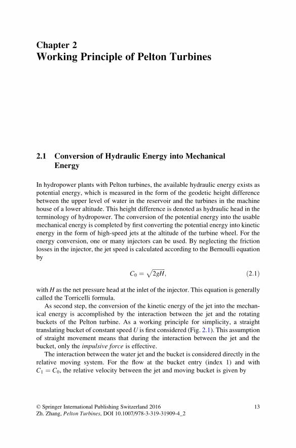
In hydropower plants with Pelton turbines, the available hydraulic energy exists as
potential energy, which is measured in the form of the geodetic height difference
between the upper level of water in the reservoir and the turbines in the machine
house of a lower altitude. This height difference is denoted as hydraulic head in the
terminology of hydropower. The conversion of the potential energy into the usable
mechanical energy is completed by first converting the potential energy into kinetic
energy in the form of high-speed jets at the altitude of the turbine wheel. For the
energy conversion, one or many injectors can be used. By neglecting the friction
losses in the injector, the jet speed is calculated according to the Bernoulli equation
by
C0 ¼ffiffiffiffiffiffiffiffiffi2gH
p; ð2:1Þ
with H as the net pressure head at the inlet of the injector. This equation is generally
called the Torricelli formula.
As second step, the conversion of the kinetic energy of the jet into the mechan-
ical energy is accomplished by the interaction between the jet and the rotating
buckets of the Pelton turbine. As a working principle for simplicity, a straight
translating bucket of constant speedU is first considered (Fig. 2.1). This assumption
of straight movement means that during the interaction between the jet and the
bucket, only the impulsive force is effective.The interaction between the water jet and the bucket is considered directly in the
relative moving system. For the flow at the bucket entry (index 1) and with
C1 ¼ C0, the relative velocity between the jet and moving bucket is given by
© Springer International Publishing Switzerland 2016
Zh. Zhang, Pelton Turbines, DOI 10.1007/978-3-319-31909-4_213
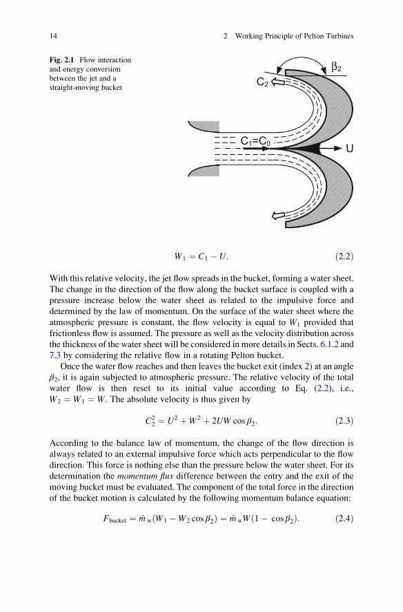
W1 ¼ C1 � U: ð2:2Þ
With this relative velocity, the jet flow spreads in the bucket, forming a water sheet.
The change in the direction of the flow along the bucket surface is coupled with a
pressure increase below the water sheet as related to the impulsive force and
determined by the law of momentum. On the surface of the water sheet where the
atmospheric pressure is constant, the flow velocity is equal to W1 provided that
frictionless flow is assumed. The pressure as well as the velocity distribution across
the thickness of the water sheet will be considered in more details in Sects. 6.1.2 and
7.3 by considering the relative flow in a rotating Pelton bucket.
Once the water flow reaches and then leaves the bucket exit (index 2) at an angle
β2, it is again subjected to atmospheric pressure. The relative velocity of the total
water flow is then reset to its initial value according to Eq. (2.2), i.e.,
W2 ¼ W1 ¼ W. The absolute velocity is thus given by
C22 ¼ U2 þW2 þ 2UW cos β2: ð2:3Þ
According to the balance law of momentum, the change of the flow direction is
always related to an external impulsive force which acts perpendicular to the flow
direction. This force is nothing else than the pressure below the water sheet. For its
determination the momentum flux difference between the entry and the exit of the
moving bucket must be evaluated. The component of the total force in the direction
of the bucket motion is calculated by the following momentum balance equation:
Fbucket ¼ _m w W1 �W2 cos β2ð Þ ¼ _m wW 1� cos β2ð Þ: ð2:4Þ
C2
β2
UC1=C0
Fig. 2.1 Flow interaction
and energy conversion
between the jet and a
straight-moving bucket
14 2 Working Principle of Pelton Turbines
Fbucket denotes the force exerted by the water on the bucket. Moreover, _m w ¼ ρWAjet is the total mass flow of water in the relative frame of the moving bucket. It is
related to the mass flow rate _m c ¼ ρC0Ajet in the absolute frame by the relation
_m w ¼ W
C0
� _m c: ð2:5Þ
This equation states that because of κ ¼ C0=W > 1, a jet piece leaving the injector
nozzle within one second will need κ seconds in order to completely reach and enter
the moving bucket. The factor κ can therefore also be understood as a time factor.
For this reason, the impulsive force exerted on the bucket, as given in Eq. (2.4), may
be rewritten as
Fbucket ¼ _m c
W2
C0
1� cos β2ð Þ: ð2:6Þ
The power, received by the bucket, is thus calculated as
P ¼ FbucketU ¼ _m c
W2
C0
1� cos β2ð Þ � U: ð2:7Þ
Although the condition for maximum power output can be calculated from dP=dU¼ 0 leading to U=C0 ¼ 1=3, this condition, however, does not represent the
condition for the maximum conversion of the kinetic energy stored in the jet into
mechanical energy of the moving bucket. To reveal the energy conversion process,
the specific energy (J/kg) of the jet must be taken into consideration. Therefore, a
unit mass of water (1 kg) is assumed to flow out of the injector nozzle within the
time tc ¼ 1= _m c. This mass of fluid will then need a time of tcκ to completely reach
and enter the moving bucket. The specific work, done by its interaction with the
moving bucket, is given by
e ¼ P � tcκ: ð2:8Þ
With Eq. (2.7) as well as κ ¼ C0=W and _m ctc ¼ 1 one thus obtains
e ¼ UW 1� cos β2ð Þ: ð2:9Þ
The maximum specific work done by a unit mass of the fluid is then obtained by
setting de=dU ¼ 0. With W ¼ C0 � U it follows
U
C0
¼ 0:5: ð2:10Þ
2.1 Conversion of Hydraulic Energy into Mechanical Energy 15
Such a speed ratio represents the condition under which Pelton turbine operations
theoretically should always be configured. The specific work done by the unit mass
of the jet flow is then obtained from Eq. (2.9) to
e ¼ 1
4C20 1� cos β2ð Þ: ð2:11Þ
The exit velocity of water out of the bucket results from Eq. (2.3) as
C22 ¼
1
2C20 1þ cos β2ð Þ: ð2:12Þ
From Eq. (2.11) it is evident that the maximum specific work is obtained when the
flow angle at the bucket exit is configured to β2 ¼ 180�. It then follows
e ¼ 1
2C20: ð2:13Þ
It is obviously equal to the specific kinetic energy which is available in the jet. The
exit velocity is obtained from Eq. (2.12) as
C2 ¼ 0: ð2:14Þ
This means that the total energy stored in the jet is entirely transferred to the moving
bucket.
In practical design of Pelton turbines, the exit velocity C2 cannot be zero because
water, after leaving the bucket, has to fly away from the bucket to make the way free
for the following buckets. As a consequence, the flow angle for the exit flow has
usually been configured to be β2 � 170�. The kinetic energy corresponding to the
exit velocityC2 6¼ 0and thus remains unexploited and must be regarded as a loss. In
practice, it is often referred to as the exit or the swirling loss.The model shown in Fig. 2.1 is a hydraulic model at which for inviscid fluids the
exit loss represents the only loss in the model system. The hydraulic efficiency is
then defined as the ratio of the specific work to the specific kinetic energy in the jet.
From Eq. (2.9), with W ¼ C0 � U, this is calculated to be
ηh ¼e
C20=2
¼ 2 � 1� U
C0
� �U
C0
1� cos β2ð Þ; ð2:15Þ
or, with k ¼ U=C0,
ηh ¼ 2k 1� kð Þ 1� cos β2ð Þ: ð2:16Þ
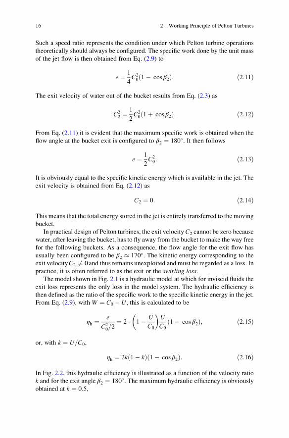
In Fig. 2.2, this hydraulic efficiency is illustrated as a function of the velocity ratio
k and for the exit angle β2 ¼ 180�. The maximum hydraulic efficiency is obviously
obtained at k ¼ 0:5,
16 2 Working Principle of Pelton Turbines
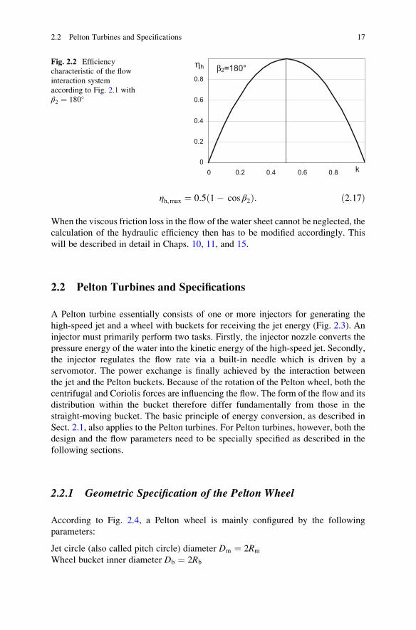
ηh,max ¼ 0:5 1� cos β2ð Þ: ð2:17Þ
When the viscous friction loss in the flow of the water sheet cannot be neglected, the
calculation of the hydraulic efficiency then has to be modified accordingly. This
will be described in detail in Chaps. 10, 11, and 15.
2.2 Pelton Turbines and Specifications
A Pelton turbine essentially consists of one or more injectors for generating the
high-speed jet and a wheel with buckets for receiving the jet energy (Fig. 2.3). An
injector must primarily perform two tasks. Firstly, the injector nozzle converts the
pressure energy of the water into the kinetic energy of the high-speed jet. Secondly,
the injector regulates the flow rate via a built-in needle which is driven by a
servomotor. The power exchange is finally achieved by the interaction between
the jet and the Pelton buckets. Because of the rotation of the Pelton wheel, both the
centrifugal and Coriolis forces are influencing the flow. The form of the flow and its
distribution within the bucket therefore differ fundamentally from those in the
straight-moving bucket. The basic principle of energy conversion, as described in
Sect. 2.1, also applies to the Pelton turbines. For Pelton turbines, however, both the
design and the flow parameters need to be specially specified as described in the
following sections.
2.2.1 Geometric Specification of the Pelton Wheel
According to Fig. 2.4, a Pelton wheel is mainly configured by the following
parameters:
Jet circle (also called pitch circle) diameter Dm ¼ 2Rm
Wheel bucket inner diameter Db ¼ 2Rb
0
0.2
0.4
0.6
0.8
0 0.2 0.4 0.6 0.8 k
β2=180° ηhFig. 2.2 Efficiency
characteristic of the flow
interaction system
according to Fig. 2.1 with
β2 ¼ 180�
2.2 Pelton Turbines and Specifications 17
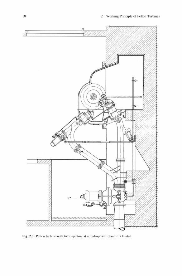
Fig. 2.3 Pelton turbine with two injectors at a hydropower plant in Kleintal
18 2 Working Principle of Pelton Turbines
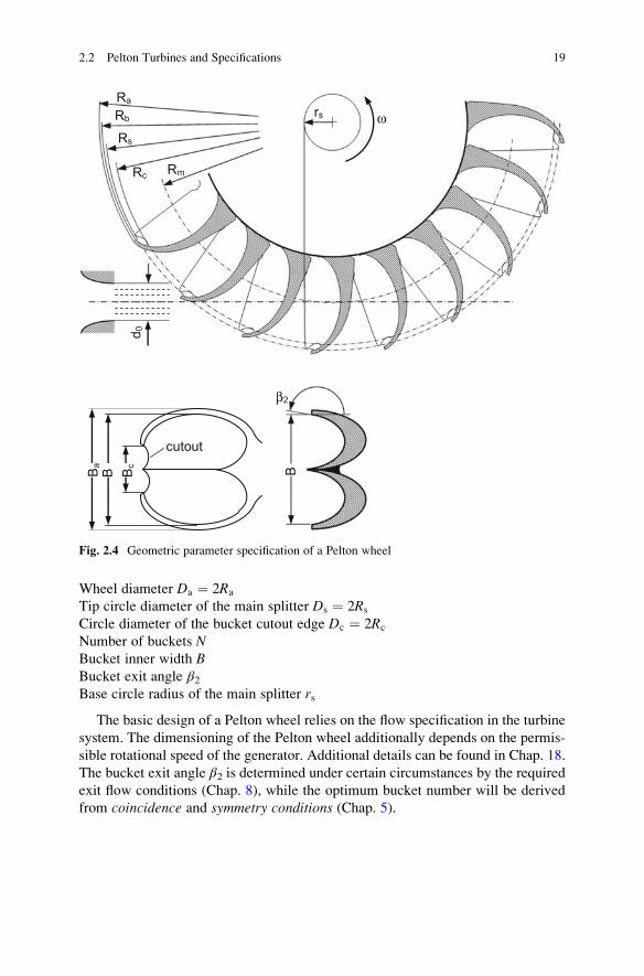
Wheel diameter Da ¼ 2Ra
Tip circle diameter of the main splitter Ds ¼ 2Rs
Circle diameter of the bucket cutout edge Dc ¼ 2Rc
Number of buckets NBucket inner width BBucket exit angle β2Base circle radius of the main splitter rs
The basic design of a Pelton wheel relies on the flow specification in the turbine
system. The dimensioning of the Pelton wheel additionally depends on the permis-
sible rotational speed of the generator. Additional details can be found in Chap. 18.
The bucket exit angle β2 is determined under certain circumstances by the required
exit flow conditions (Chap. 8), while the optimum bucket number will be derived
from coincidence and symmetry conditions (Chap. 5).
Rc
ωRs
rs
Ra
Rb
Rm
d 0
β2
BB B cB a
cutout
Fig. 2.4 Geometric parameter specification of a Pelton wheel
2.2 Pelton Turbines and Specifications 19
2.2.2 Characteristic Hydromechanical Parameters
In the field of turbomachinery, diverse dimensionless numbers function as para-
metric quantities which are often used to specify the size of the machines and to
quantify the flow performances. For Pelton turbines, however, only few of them are
relevant for the geometric and hydraulic design as well as for the turbine operations.
The most important parametric quantities are summarized in this section.
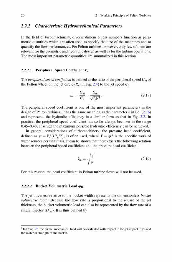
2.2.2.1 Peripheral Speed Coefficient km
The peripheral speed coefficient is defined as the ratio of the peripheral speed Um of
the Pelton wheel on the jet circle (Rm in Fig. 2.4) to the jet speed C0
km ¼ Um
C0
¼ Umffiffiffiffiffiffiffiffiffi2gH
p : ð2:18Þ
The peripheral speed coefficient is one of the most important parameters in the
design of Pelton turbines. It has the same meaning as the parameter k in Eq. (2.16)
and represents the hydraulic efficiency in a similar form as that in Fig. 2.2. In
practice, the peripheral speed coefficient has so far always been set in the range
0.45–0.48, at which the maximum possible hydraulic efficiency can be achieved.
In general considerations of turbomachinery, the pressure head coefficient,
defined as ψ ¼ Y= U2m=2
� �, is often used, where Y ¼ gH is the specific work of
water sources per unit mass. It can be shown that there exists the following relation
between the peripheral speed coefficient and the pressure head coefficient
km ¼ffiffiffiffiffi1
ψ:
sð2:19Þ
For this reason, the head coefficient in Pelton turbine flows will not be used.
2.2.2.2 Bucket Volumetric Load φB
The jet thickness relative to the bucket width represents the dimensionless bucketvolumetric load.1 Because the flow rate is proportional to the square of the jet
thickness, the bucket volumetric load can also be represented by the flow rate of a
single injector ( _Q jet). It is thus defined by
1 In Chap. 23, the bucket mechanical load will be evaluated with respect to the jet impact force and
the material strength of the bucket.
20 2 Working Principle of Pelton Turbines
φB ¼_Q jet
π=4 � B2ffiffiffiffiffiffiffiffiffi2gH
p ; ð2:20Þ
with B as the bucket inner width.
The flow rate of a single injector is given by _Q jet ¼ π=4 � d20ffiffiffiffiffiffiffiffiffi2gH
p, with d0 as the
jet diameter. Consequently, the bucket volumetric load is given by
φB ¼ d0B
� �2
: ð2:21Þ
It is simply expressed by the ratio of the jet thickness to the bucket width. Because
of its geometric feature, the bucket volumetric load expressed by Eq. (2.21) is much
more comprehensible than that of Eq. (2.20). For this reason, Eq. (2.21) will be
preferably used in this book.
The bucket volumetric load is used on the one hand to represent the flow rate in a
dimensionless form and on the other hand to determine the necessary width of the
Pelton buckets. The bucket width is usually designed so that at nominal or maxi-
mum flow rate, the jet diameter d0 does not exceed one-third of the bucket width B.This yields φB ¼ 0:09 to 0.11 as design criterion for the bucket width.
2.2.2.3 Specific Speed nq
The specific speed is a parametric quantity which has been widely used in all types
of rotating fluid machinery. In the specification of Pelton wheels, the specific speed
has a special explicit meaning. As directly taken over from the technical literature,
for instance Pfleiderer and Petermann (1986), the specific speed is defined by
nq ¼ n
ffiffiffiffiffiffiffiffi_Q jet
qH3=4
: ð2:22Þ
It is obviously not dimensionless, nor does it have the same dimension as the
rotational speed n. To avoid confusion in applications, _Q jet and H in the above
equation can be considered to be normalized by the unit flow rate _Q jet ¼ 1m3=s and
the unit pressure head H ¼ 1m, respectively. Then n and nq have the same unit,
either 1/s or 1/min. In the present work, the specific speed nq is mainly used with the
unit 1/s.
As an alternative to the specific speed defined in Eq. (2.22), the following
definition can also be found in the literature:
2.2 Pelton Turbines and Specifications 21

ny ¼ n
ffiffiffiffiffiffiffiffi_Q jet
qgHð Þ3=4
¼ n
ffiffiffiffiffiffiffiffi_Q jet
qY3=4
: ð2:23Þ
In this definition, the unit of the rotational speed is 1/s.
Between the two definitions of the specific speed, the following relation exists:
nq ¼ g3=4ny ¼ 5:54ny 1=sð Þ: ð2:24Þ
One obtains further by using the unit 1/min for the speed,
nq ¼ 333ny 1=minð Þ: ð2:25Þ
The specific speed is primarily used when for a given flow rate and a given pressure
head, a Pelton turbine should be defined by specifying the injector number, the
rotational speed, and the wheel dimension. The exact computational algorithm for
the design of a Pelton turbine by using the specific speed is presented in detail in
Chap. 18. For practical engineering applications, only the specific speed according
to Eq. (2.22) is used in this book.
It should also be noted that the specific speed indeed represents the diameter
ratio δ ¼ Dm=d0 which is a dimensionless quantity and called the diameter number
(Sigloch 2006). This can be confirmed using Eq. (2.22) by considering the flow rate_Q jet ¼ 1
4πd20
ffiffiffiffiffiffiffiffiffi2gH
pand the peripheral speed coefficient according to Eq. (2.18). One
obtains
nq ¼ g3=4km
21=4ffiffiffiπ
p d0Dm
¼ 2:63kmd0Dm
1=sð Þ: ð2:26Þ
Here, the significance of the specific speed is clearly explained. Since the peripheral
speed coefficient km of Pelton turbines is practically a constant, the specific speed
represents exclusively the diameter ratio d0/Dm and is therefore essentially a
geometric parameter. With respect to the bucket volumetric load according to
Eq. (2.21), the specific speed is also interpreted as
nq ¼ 2gð Þ3=42
ffiffiffiπ
p kmffiffiffiffiffiffiφB
p B
Dm
¼ 2:63kmffiffiffiffiffiffiφB
p B
Dm
: ð2:27Þ
According to this equation and under nominal operations, at which φB � 0:11, thespecific speed also specifies the geometric design parameter (B/Dm) of the Pelton
wheel.
As the specific speed is, according to its definition in Eq. (2.22), directly
determinable from the flow rate and the pressure head, it is a particularly convenient
parameter for the design of a Pelton turbine from the given _Q jet and H. For this
reason, the diameter number δ ¼ Dm=d0 will not be used in this book.
22 2 Working Principle of Pelton Turbines
2.2.2.4 Characteristic Bucket Position Angle αo
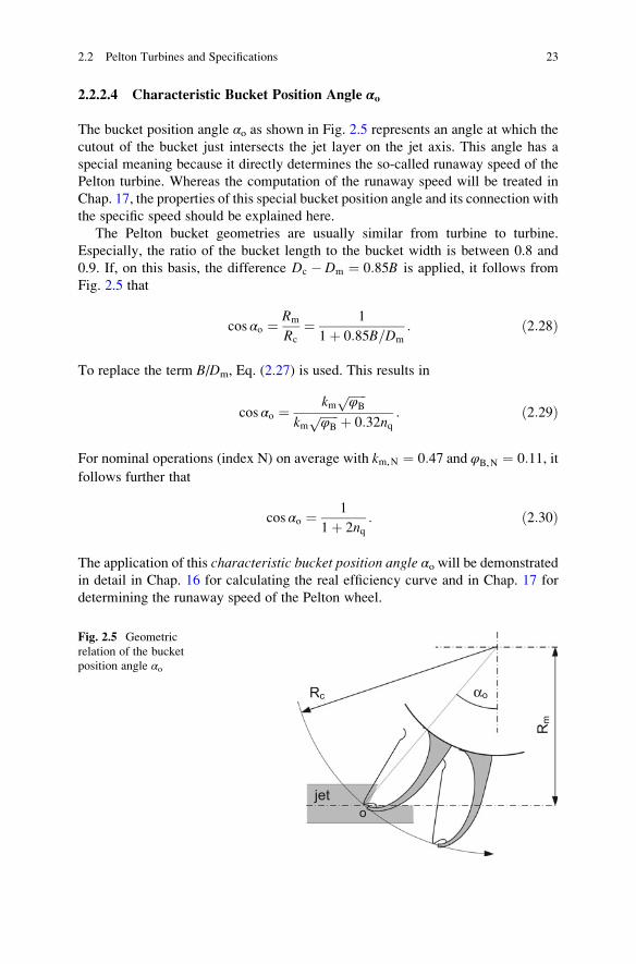
The bucket position angle αo as shown in Fig. 2.5 represents an angle at which the
cutout of the bucket just intersects the jet layer on the jet axis. This angle has a
special meaning because it directly determines the so-called runaway speed of the
Pelton turbine. Whereas the computation of the runaway speed will be treated in
Chap. 17, the properties of this special bucket position angle and its connection with
the specific speed should be explained here.
The Pelton bucket geometries are usually similar from turbine to turbine.
Especially, the ratio of the bucket length to the bucket width is between 0.8 and
0.9. If, on this basis, the difference Dc � Dm ¼ 0:85B is applied, it follows from
Fig. 2.5 that
cos αo ¼ Rm
Rc
¼ 1
1þ 0:85B=Dm
: ð2:28Þ
To replace the term B/Dm, Eq. (2.27) is used. This results in
cos αo ¼km
ffiffiffiffiffiffiφB
pkm
ffiffiffiffiffiffiφB
p þ 0:32nq: ð2:29Þ
For nominal operations (index N) on average with km,N ¼ 0:47 and φB,N ¼ 0:11, it
follows further that
cos αo ¼ 1
1þ 2nq: ð2:30Þ
The application of this characteristic bucket position angle αo will be demonstrated
in detail in Chap. 16 for calculating the real efficiency curve and in Chap. 17 for
determining the runaway speed of the Pelton wheel.
Rc
Rm
o
αo
jet
Fig. 2.5 Geometric
relation of the bucket
position angle αo
2.2 Pelton Turbines and Specifications 23
2.2.2.5 Peripheral Speed of the Bucket Cutout Edge
Another frequently used reference speed in flow calculations is the peripheral speedof the cutting edge of the bucket cutout. From Eqs. (2.28) and (2.30), one first
obtains the diameter ratio
Dc
Dm
¼ 1þ 2nq: ð2:31Þ
The ratio of the corresponding peripheral speed to the jet speed is, in view of
Eq. (2.18), given by
Uc
C0
¼ Um
C0
Uc
Um
¼ kmDc
Dm
: ð2:32Þ
With Eq. (2.31) it follows further that
Uc
C0
¼ km 1þ 2nq� �
: ð2:33Þ
2.2.3 Hydromechanical Specification of the Pelton Turbine
The main operating parameters of a Pelton turbine are the peripheral speedcoefficient km and the bucket volumetric load φB, while the specific speed only
determines the shape of the Pelton wheel and is thus related to the nominal
operation. On the one hand, both parameters, km and φB, describe the hydraulic
similarity between two Pelton wheels with similar geometric designs and therefore
the same specific speed (see Chap. 20). On the other hand, they together determine
the flow mechanical efficiency of a Pelton turbine. With regard to the maximum
efficiency, the operation point of a Pelton turbine is commonly configured by the
peripheral speed coefficient km ¼ 0:45�0:48 and the bucket volumetric load
φB ¼ 0:09�0:11.To describe the flow mechanical interaction between the jet and the rotating
buckets of a Pelton turbine, basically the same calculation is used as described in
Sect. 2.1 for the straight-moving bucket. The relative flow velocity at the bucket
entry is assumed to beW1 ¼ C0 � Um. Analogous to Eq. (2.6), the interaction, i.e.,
the impulsive force exerted on a bucket, is obtained as
Fbucket ¼ _m cC0 1� kmð Þ2 1� cos β2ð Þ: ð2:34Þ
24 2 Working Principle of Pelton Turbines
Contrary to the case of the straight-moving bucket, each jet in a Pelton turbine with
rotating buckets simultaneously interacts with about two buckets. More accurately,
the number of buckets interacting with one jet is given by
2λ ¼ _m c
_m w
¼ C0
W1
: ð2:35Þ
Here, λ denotes the multi-bucket factor. Its application will be explained in detail inChap. 5. Accordingly, the total impulsive force resulting from one jet is given by
Fjet ¼ 2λFbucket ¼ _m c
C20
W1
1� kmð Þ2 1� cos β2ð Þ: ð2:36Þ
Because W1 ¼ C0 � Umð Þ ¼ C0 1� kmð Þ, there follows
Fjet ¼ _m cC0 1� kmð Þ 1� cos β2ð Þ: ð2:37Þ
The power exchange achieved by one jet flow is thus
P ¼ FjetUm ¼ _m cC20km 1� kmð Þ 1� cos β2ð Þ: ð2:38Þ
The maximum power achieved is given at km,max which is obtained by the condition
dP=dkm ¼ 0 and obtains
km,max ¼ 0:5: ð2:39Þ
From Eq. (2.38) the hydraulic efficiency thus results as
ηh ¼P
12_m cC
20
¼ 2km 1� kmð Þ 1� cos β2ð Þ: ð2:40Þ
Formally this expression agrees with Eq. (2.16). The reason for this agreement is
that perpendicular entry of the jet into the bucket was assumed and thus the relation
W1 ¼ C0 � Um was used. Therefore, Eq. (2.40) can be considered to be directly
taken over from Eq. (2.16). Because of the assumptionW1 ¼ C0 � Um, it, therefore,
only applies to illustrate the working principle of a Pelton turbine and to
roughly estimate the hydraulic efficiency. In particular, the speed ratio
κ ¼ C0=W1, which in Eq. (2.5) was referred to as a time factor, stands here for
the number of buckets that simultaneously interact with a jet. In Chaps. 5 and 7, this
factor will be replaced by the multi-bucket factor λ ¼ κ=2 that is computed using
other, different reasoning.
In fact, all equations derived so far for Fjet, P, and ηh only represent the
operational principle of a Pelton turbine. Both the jet impact force and the power
exchange in a Pelton turbine with rotating buckets behave somewhat differently
than those in a nonrotating, i.e., linearly translating bucket. The interaction between
2.2 Pelton Turbines and Specifications 25

the jet and the rotating buckets is no longer constant but varies with time. The
consideration of a linearly translating bucket in Sect. 2.1 has led to the speed ratio
U=C0 ¼ 0:5 at which the maximum hydromechanical performance is achieved. In
practical operations of Pelton turbines, however, the nominal peripheral speed
coefficient km,N for maximum efficiency is found to be between 0.45 and 0.48.
Here, particular attention should be focused on the fact that the water, after the
energy exchange with the rotating buckets, still possesses sufficient kinetic energy
to be able to leave the buckets in time. The associated loss is called the exit orswirling loss. The full term of the hydraulic efficiency will be presented in Chap. 15
once all individual hydromechanical losses, including the viscous friction effect,
have been treated.
The hydraulic efficiency according to Eq. (2.40) has been shown to be a function
of the peripheral speed coefficient and theoretically reaches its maximum at
km,max ¼ 0:5. On the other hand, the hydraulic efficiency of a Pelton turbine also
depends on the bucket volumetric load φB. Figure 2.6 shows such a dependence of a
Pelton turbine obtained by measurements. Usually, the nominal flow rate of a
Pelton turbine is designed with a bucket load of about φB,N ¼ 0:1. Most Pelton
turbines, however, show maximum efficiencies at the flow rate below that value, as
this is also confirmed in Fig. 2.6. The basic reason for this intention is that nearly all
Pelton turbines also operate at partial loads. As can be recognized, the hydraulic
efficiency of a Pelton turbine only insignificantly changes with bucket load when
compared with other types of turbines. This is the reason why the Pelton turbines
are often used to balance the load of the network. The perceptible decrease of the
hydraulic efficiency at a partial load is ascribed to friction effects; see Sect. 10.4 as
well as Sect. 11.4.
Fig. 2.6 Hydraulic efficiency of a Pelton turbine (KWO) plotted against the bucket volumetric
load
26 2 Working Principle of Pelton Turbines

2.2.4 Installation Form of Pelton Turbines
The practical installation forms of Pelton turbines have been categorized by the
orientation of the turbine axis. The turbines with horizontal axes are denoted
horizontal turbines (Fig. 2.7a) and those with vertical axes are called vertical
(a) Horizontal
(b) Vertical
Fig. 2.7 Different installation forms of Pelton turbines at the Oberhasli Hydroelectric Power
Company (KWO). (a) Horizontal, (b) vertical
2.2 Pelton Turbines and Specifications 27
turbines (Fig. 2.7b), respectively. The horizontal installation is only suitable for
turbines with at most two injectors. Vertical turbines can be designed with up to six
injectors. The significant advantage of the vertical installation is that the injectors
can be and are distributed symmetrically around the wheel. For Pelton turbines with
one injector or in all cases of turbines of horizontal installation, the destructive
one-sided bearing load is inevitable. For turbines with two or more injectors, care
should be taken that no collisions between two jets could occur in the same bucket.
The offset angle between two adjacent injectors must be sufficiently large to ensure
trouble-free interaction between the jet and the rotating buckets, as well as trouble-
free exit flow of water out of the buckets. The relevant criterion will be elaborated
in Chap. 19. In the design of vertical turbines, one has to ensure that water after
leaving the upper bucket halves should not fall back on the wheel. The relevant
criterion is explained in Chap. 8.
2.2.5 Parameter Notations
In addition to the geometric parameters of a Pelton wheel that have already been
shown in Fig. 2.4, complete geometric and hydraulic parameters of both the injector
and the Pelton wheel are summarized in Appendix A. Other derived parametric and
dimensionless quantities are summarized in Appendix B.
References
Pfleiderer, C., & Petermann, H. (1986). Str€omungsmaschinen (5. Auflage). Springer.
Sigloch, H. (2006). Str€omungsmaschinen. (3. Auflage). Hanser Verlag.
28 2 Working Principle of Pelton Turbines

http://www.springer.com/978-3-319-31908-7