working with inroads selectcad - university of idaho · is a hallmark feature of civil engineering...
TRANSCRIPT

Working With
InRoads SelectCAD
DEA410160 ISG00001A-1/0820

ii
Warranties and Liabilities All warranties given by Bentley Systems, Inc. about equipment or software are set forth in your purchase contract, and nothing stated in, or implied by, this document or its contents shall be considered or deemed a modification or amendment of such warranties. The information and the software discussed in this document are subject to change without notice and should not be considered commitments by Bentley Systems. Bentley Systems assumes no responsibility for any error that may appear in this document. The software discussed in this document is furnished under a license and may be used or copied only in accordance with the terms of this license. No responsibility is assumed by Bentley Systems for the use or reliability of software on equipment that is not supplied by Bentley Systems or its affiliated companies. Trademarks Bentley, MicroStation, the “B” Bentley logo, MDL, and MicroStation GeoGraphics are registered trademarks of Bentley Systems, Incorporated. Adobe, the Adobe logo, Acrobat, the Acrobat logo, Distiller, Exchange, and PostScript are trademarks of Adobe Systems Incorporated. Windows and Windows NT are registered trademarks of Microsoft Corporation. NT is a trademark of Northern Telecom Limited. All other brands and product names are trademarks of their respective owners. Copyright 2001 Bentley Systems Incorporated All Rights Reserved Including software, file formats, and audiovisual displays; may be used pursuant to applicable software license agreement; contains confidential and proprietary information of Bentley Systems and/or third parties which is protected by copyright and trade secret law and may not be provided or otherwise made available without proper authorization. RESTRICTED RIGHTS LEGEND Use, duplication, or disclosure by the government is subject to restrictions as set forth in subparagraph (c) (1) (ii) of The Rights in Technical Data and Computer Software clause at DFARS 252.227-7013 or subparagraphs (c) (1) and (2) of Commercial Computer Software -- Restricted Rights at 48 CFR 52.227-19, as applicable. Unpublished -- rights reserved under the copyright laws of the United States. Bentley Systems Incorporated 9238 Madison Blvd., Suite 117 West Madison, Alabama 35894-0001

i
Table of Contents Introducing InRoads SelectCAD........................................................... 1
InRoads and the SelectCAD Product Suite ........................................ 1 InRoads SelectCAD Version 8.2: What’s New?................................ 3 About Your Documentation ............................................................... 4 Product Training: Learn It Your Way ................................................ 5
Bentley Systems Facility Training.......................................... 5 On-Site Training........................................................................ 5 Customized Training Courses ................................................. 5 Long Distance Learning ........................................................... 5
Typeface Conventions Used in InRoadsSC Documentation.............. 7 What You Need to Know Before Working with InRoads SelectCAD7
Getting Started........................................................................................ 9 In Windows 2000, Windows NT 4.0, and Windows 98/ME.............. 9
CAD Package Requirements ....................................................... 9 Downloading from the CD .......................................................... 9 Downloading Across the Network............................................. 10
Starting InRoads SelectCAD............................................................ 10 Exiting InRoads SelectCAD............................................................. 11
Using InRoads SelectCAD.................................................................... 13 An Overview .................................................................................... 13 Basic Concepts in InRoads SelectCAD............................................ 13
Digital Terrain Model ................................................................ 14 Types of DTM Display .............................................................. 15 Symbology................................................................................. 16
Named Symbology with Symbology Manager ................... 16 Command-level Symbology................................................ 20
Features in the DTM.................................................................. 20 Intelligent Features.............................................................. 21 Feature Styles with Feature Style Manager......................... 21
View Surface Features .................................................. 26 Viewing Surface Features using the Feature Selection Filter.............................................................................. 28 Feature Properties ......................................................... 31 Annotating Features...................................................... 32
Preferences................................................................................. 34 Basic Preferences ................................................................ 34 Preference Manager............................................................. 36 Surface Preference............................................................... 40

Working with InRoads SelectCAD
ii
Preferred Preference............................................................ 41 Locks.......................................................................................... 44 Feature Filter Lock..................................................................... 44 Style Lock.................................................................................. 46 Write Lock ................................................................................. 48 Pencil/Pen Mode........................................................................ 48 Delete Ink Lock ......................................................................... 51 Locate Graphics/Features .......................................................... 53 Point/Element/No Snap Lock ................................................... 54 Station Lock............................................................................... 55 Report Lock .............................................................................. 55
General InRoads SelectCAD Review............................................... 56 Comprehensive Data Structure .................................................. 56
Horizontal and Vertical Alignments.................................... 56 Typical Sections .................................................................. 57 Side Slopes .......................................................................... 57 Evaluation............................................................................ 58 Superelevation..................................................................... 58 The Roadway Model ........................................................... 58 Drawing Production ............................................................ 59 Reports ................................................................................ 59 Visualization........................................................................ 59
Getting Around in InRoads SelectCAD ........................................... 60 Using the Interface..................................................................... 60
Accepting/Rejecting Solutions ............................................ 64 Using Access Control.......................................................... 65
Menus ........................................................................................ 66 Menus and Application Add-Ins................................................ 67
Customize Menus................................................................ 68 Customize Toolbars............................................................. 69 Shortcut Keys to InRoads SelectCAD Commands ............. 73 Customize Macros............................................................... 74 Exporting Custom Settings.................................................. 75 Importing Custom Settings.................................................. 76
Using the Online Help System ......................................................... 77 SelectCAD Help Topics............................................................. 77
Looking at InRoads SelectCAD Workflows ....................................... 79 Master Workflow ............................................................................. 79 Creating an Overall Project .............................................................. 80 Creating a Surface ............................................................................ 80 Extracting Profiles............................................................................ 81 Creating or Editing Vertical Alignments.......................................... 82 Creating or Editing Typical Sections ............................................... 82 Defining Side Slopes........................................................................ 83

Table of Contents
iii
Defining Side Slopes with Cut/Fill Tables................................. 83 Defining Side Slopes with Material Tables...................................... 83 Defining Side Slopes with Decision Tables............................... 84 Creating and Calculating Superelevations ................................. 84 Defining the Roadway...................................................................... 85 Running the Roadway Modeler........................................................ 85 Reviewing the Design Surface ......................................................... 85 Extracting Cross Sections................................................................. 86 Computing Volumes ........................................................................ 86 Creating Reports............................................................................... 86
Learning InRoads SelectCAD.............................................................. 89 Prerequisites ..................................................................................... 89 Saving Your Work ........................................................................... 90 Before Starting Each Lesson ............................................................ 90 Basic Roadway Design..................................................................... 91
Lesson 1: Starting InRoads SelectCAD..................................... 92 Setting Units of Measure ........................................................... 93 Lesson 2: Digital Terrain Modeling........................................... 96
Before Getting Started......................................................... 96 Creating a Surface ............................................................... 96 Loading an ASCII Surface .................................................. 98
Terrain Model Display............................................................. 103 Creating Named Symbology ............................................. 103 Creating a Surface Preference ........................................... 108
Displaying a Surface Perimeter .................................. 109 Displaying Surface Contours ...................................... 111 Using the Write Lock.................................................. 113 Using Write Lock with Pencil/Pen ............................. 115 Displaying Surface Triangles...................................... 118
Creating a Feature Style .................................................... 120 Creating a Feature Selection Filter .................................... 123 Displaying Surface Features.............................................. 125
Lesson 3: Horizontal Alignment Design................................. 128 Setting Work Session Options........................................... 128 The Geometry Project ....................................................... 132
Creating a Geometry Project....................................... 132 Creating an Alignment by Horizontal Curve Set........ 135 Creating an Alignment by Horizontal Element Design143 Defining the Beginning Station .................................. 151 Reviewing the Horizontal Alignment ......................... 152 Resolving Discontinuties in a Horizontal Alignment . 154 Displaying the Alignment Stationing ......................... 156
Lesson 4: Profiles.................................................................... 161

Working with InRoads SelectCAD
iv
Generating a Profile Along an Alignment......................... 162 Lesson 5: Vertical Alignments ............................................... 165
Creating a New Vertical Alignment .................................. 165 Creating an Alignment by Vertical Curve Set ............ 166 Creating an Alignment by Vertical Element Design .. 171 Reviewing a Vertical Alignment ................................ 179
Profile Annotation ............................................................. 180 Displaying Vertical Alignment Annotation ................ 180
Lesson 6: Plan and Profile Generator ..................................... 183 Before You Start This Lesson ........................................... 183 Defining and Creating the Views ...................................... 184 Saving the VDF................................................................. 197
Lesson 7: Typical Sections ..................................................... 198 Creating a Typical Section Library ................................... 199 Defining Transition Controls............................................. 200
Creating Transition Control Entries............................ 200 Defining Typical Sections................................................. 208
Creating a Typical Section Template.......................... 209 Adding Segments to a Template Layer....................... 211
Lesson 8: Decision Tables ...................................................... 215 Creating a Decision Table ................................................. 216 Creating Decision Table Segments ................................... 217
Lesson 9: Roadway Libraries.................................................. 230 Creating a New Roadway Library..................................... 231 Creating a Roadway Definition......................................... 232
Lesson 10: Roadway Modeler ................................................ 236 Loading Other Files........................................................... 237 Generating a Roadway Model........................................... 237 Creating a Projects File ..................................................... 241
Lesson 11: Design Evaluation ................................................ 244 Volume Computation Methods ......................................... 244 Extracting Cross Sections.................................................. 245 Computing End-Area Volumes ......................................... 247
Lesson 12: Final Plan Sheets .................................................. 250 Creating Final Plan and Profile Sheets.............................. 250
Summary.................................................................................. 252
How to Reach Bentley Systems.......................................................... 253 Electronic Self-Help Support ......................................................... 253 Bentley Systems World Wide Web Information Server ................ 253 Bentley Systems Civil Engineering Knowledge Bases .................. 253 Logging Customer-Support Worksheets ........................................ 254
Information You Need When Requesting Support .................. 254 About You......................................................................... 254 About Your Bentley Systems Software............................. 254

Table of Contents
v
About Your Computer System.......................................... 254 If We Need Your Data to Reproduce a Problem .............. 255
Telephone Numbers................................................................. 255 Bentley Systems Corporate Education Services................ 255 Bentley Systems Customer Response Center.................... 255 Bentley Systems Customer Services ................................. 255
North American Service Plans................................................. 255 Complimentary Service..................................................... 255
30-day phone support.................................................. 255 Premium Service ............................................................... 256
Full support for all Bentley Systems-developed product software....................................................................... 256
Advantage Service............................................................. 257
Horizontal Alignment Review............................................................ 259
Vertical Alignment Review ................................................................ 261
Glossary ............................................................................................... 263
Index..................................................................................................... 289

Working with InRoads SelectCAD
vi

1
1Introducing InRoads SelectCAD
Welcome to InRoads SelectCAD®! The latest in transportation engineering software by Bentley Systems, InRoads SelectCAD is a one-stop solution for transportation engineers and civilworks professionals. InRoads SelectCAD provides a comprehensive set of tools for transportation system design, civil and site engineering for roadways, highways, waterways, and airports. Developed using the familiar Microsoft® Windows standards, InRoads SelectCAD runs on the Microsoft Windows NT®, Windows® 98/ME and Windows® 2000 operating systems.
InRoads SelectCAD lets you work in a graphic environment to create a 3-D digital surface, create horizontal and vertical alignments, cut profiles, define template criteria and roadway conditions, generate cross-sections and 3-D model, calculate volumes, generate reports, evaluate the design, and create plan and profile sheets. These extensive features, along with additional application add-in tools, make designing a complex highway system or simply laying out a small subdivision an interactive and easy process.
With InRoads SelectCAD, you can continue using the computer-aided design (CAD) platform with which you are familiar. When starting the product, you can select AutoCAD® 2000i or Release 14, or MicroStation® SE/J, as your CAD engine. This SelectCAD environment is a hallmark feature of civil engineering solutions by Bentley Systems.
InRoads and the SelectCAD Product Suite InRoads SelectCAD is a member of the SelectCAD product suite.
1

Working with InRoads SelectCAD
2
In fact, the SelectCAD product suite includes six civil engineering products:
! InRoads SelectCAD provides complete solutions from field to design to construction for the transportation professional.
! Site SelectCAD provides site design and digital terrain modeling, lot layout, and geometry for civil-works, environmental, and site-development projects. Site SelectCAD is a subset of InRoads SelectCAD
! Rail SelectCAD provides advanced production tools for track layout and railway design.
! Survey SelectCAD helps surveyors transfer electronic field book data into the graphics environment.
! Bridge SelectCAD helps bridge design professionals define geometry and model complex, continuous-span bridges or simple span bridges.
! Storm and Sanitary SelectCAD is the first software to offer an integrated package for storm water and sanitary sewer design, combining the power of CAD with proven analytical tools and enhanced interactive graphics.

Introducing InRoads SelectCAD
3
1InRoads SelectCAD Version 8.2: What’s New?
InRoads SelectCAD, Version 8.2 offers several new commands and enhanced features:
! SelectCAD Workspace Explorer. This enhanced organization and display feature allows new ways to interact with project data. Tabs allow you to display a view of specific SelectCAD objects within the overall project. Views correspond to sub-trees within the Explorer. For example, click the Surfaces tab to display only surface data within the project. You can “tear away” the view and the Workspace bar containing the sub-tree can be docked at any location on the screen for easy access. InRoads provides the following predefined views: Surfaces, Geometry, Typical Sections, Roadways, and Preferences. See Chapter 3, Using InRoads SelectCAD for more details.
! Evaluation. Cross sections are specified as a set, by name (defaults to the active horizontal alignment name). The Rename Set command allows you to modify set names. You can now create cross sections with an unlimited number of surfaces, and symbology is always taken from the surface. Slope length is now available for the Annotate Cross Section command. Label Points (for offset and elevation), Label Segments (for slope, slope length, horizontal width and vertical depth) are new commands and Cross Section Editor has been modified.
Profiles function similar to cross sections with named sets, unlimited surfaces, and with features included when the profile is created. They utilize Symbology Manager and Feature Style Manager to govern symbology and feature styles. There are enhancements to Surface Properties and Offsets (16 per surface and stored in the DTM). The new Update Profile command allows you to update/refresh/turn on or off a profile elements during the design process. The new Annotate Feature in Profile command allows for annotating points and line segments. Profiles also include new Label Points and Label Segments commands.
Plan and Profile Generator now includes Match Lines.
! Modeler. Reserved transition control names can now be renamed. Transition control items can be multi-deleted. Transition control tab items can be sorted. The internal names of the roadway library (.rwl) and the typical section library (.tml) can now be renamed. Features can be used as targets in a

Working with InRoads SelectCAD
4
decision table. Superelevation pivot points can now be offset vertically from a design layer. Modeler now automatically sets the surface properties for plan, profile, and cross section symbology to the surface name.
! Geometry. Updates to geometry include changes in the Explorer with integrity checks and the inclusion of parabolic to vertical circle feature. Enhancements to commands include Edit Horizontal Event Points, Edit Horizontal Element (to maintain connectivity), and Copy Horizontal Element (paralleling option). Similar changes also appear in the Edit Vertical commands.
The new View Curve Set command allows for annotating horizontal curve sets. The new View Station Base/Clearance command allows for annotating station and offsets. The new Vertical Change in Plan command allows for annotating vertical geometry in plan view.
! Advanced Geometry. The new Horizontal Regression and Vertical Regression commands allow for advanced mathematical computations. Regression points can be added from multiple sources. Advanced analysis (single or multi-element regression) can be performed utilizing data ordering, curvature, and slew diagrams
Experienced users will continue to find advanced programming features such as the Run Macro command that allows software customization for specialized environments.
About Your Documentation To assist the beginning and advanced user, InRoads SelectCAD provides two complementary forms of documentation. The software kit includes:
! Working With InRoads SelectCAD. Delivered as Adode® Acrobat® Portable Document Format (PDF) files, this introductory document contains information on getting started, common design workflows, and a tutorial and sample data set that provides step-by-step instructions for learning how to create a new road.
! SelectCAD Help Topics. This comprehensive online reference material consists of help topics that detail each command and dialog box parameter within the product.

Introducing InRoads SelectCAD
5
1Product Training: Learn It Your Way
In addition to the documentation provided with your software, Bentley Systems Civil Engineering provides various levels and forms of product training.
Bentley Systems Facility Training
Standard courses are offered at various times throughout the year. You can also schedule a custom class to he held at any Bentley Systems facility that offers a training center. For training facility information or a complete listing of training courses, visit the Bentley Systems website at Standard civil courses include:
! Road Design Basics ! InRoads Basics ! InRoads Survey ! InRoads SelectCAD ! Site SelectCAD ! Storm & Sanitary SelectCAD ! Survey SelectCAD ! Bridge SelectCAD
On-Site Training
On-site training can consist of the standard course offerings on SelectCAD civil engineering products or customized training. You are allowed up to 12 students in an on-site training course.
Customized Training Courses
Customized training courses are available for customers whose training requirements exceed our standard offerings. You determine the content of the course based on your requirements. You can use your data and specific workflow - utilizing our industry experts to help meet production and design deliverables. Customized training is offered at an Bentley Systems facility, at your site, or by Long Distance Learning (LDL).
Long Distance Learning
LDL is a combination of state-of-the-art technology with specialized workflow training. Developed by product experts, LDL utilizes the World Wide Web to communicate in a “give and take” classroom environment. These training sessions are inexpensive - no travel is required because it

Working with InRoads SelectCAD
6
can be done from your desktop or local conference room. Use your specific data and workflow with an unlimited number of students in attendance at your location. The sessions are available in 2-hour increments.
For more information on civil product training, 1-877-705-7471 ext. 5422. Also, see Appendix A, How To Reach Bentley Systems for more information.

Introducing InRoads SelectCAD
7
1Typeface Conventions Used in InRoads SelectCAD Documentation
ALL CAPS Keyboard keys
If keys are separated by a comma, press them in sequence. For example: ALT,F5. If they are joined by a plus sign, press them at the same time.
For example: CTRL+z. Bold Unserifed Type
An item in the graphical interface, such as the title of a dialog box or a tool. Paths through menus use right angle brackets between items you click.
For example: Click File > Open to load a file. CourierType
Information you type.
For example: Type breaklines.dat in the dialog box field.
Italic type A document or section title, the first occurrence of a new or special term, directory and file names, or information about what the software is doing.
For example: The civil.ini file contains preference settings.
What You Need to Know Before Working with InRoads SelectCAD
While InRoads SelectCAD is a comprehensive design package, it is also an intuitive product in which a new user could become productive in a short time with some assistance. The documentation and tutorial in InRoads SelectCAD assume that you have:
! A basic understanding of the computer operating system
! The ability to move around in the Windows environment
! Working understanding of your CAD system
! General knowledge of engineering concepts and terms

Working with InRoads SelectCAD
8

9
2
Getting Started InRoads SelectCAD can be installed on Intel-based hardware using the Windows 2000, Windows 98/ME, or Windows NT 4.0 (Service Packs 4 and 5), operating system. The following instructions assume that you have already installed one of these operating systems on your machine. You must also have installed CAD software on your machine. InRoads SelectCAD will run on AutoCAD 2000/Map 2000/Release 14, and MicroStation SE/J. See the CAD Package Requirements section that matches your operating system for a list of software tools.
In Windows 2000, Windows NT 4.0, and Windows 98/ME
This section details what you need to efficiently run InRoads SelectCAD.
CAD Package Requirements ! CAD software (one of the following): AutoCAD, version 2000i, Map
2000 or Release 14, Patch E; MicroStation, Version SE or J.
! Pentium 200 Mhz minimum, 400 Mhz or more recommended
! 64MB RAM minimum, 128MB or more recommended
! 150MB disk space minimum, 200MB or more recommended
! VGA or better
! Access to a CD-ROM drive
! Mouse or compatible digitizer for input
! Compatible plotter or printer for output (optional)
Downloading from the CD Prior to installing InRoads SelectCAD, make sure you have exited all other civil engineering software. In Windows 2000, the setup program automatically starts when the CD is loaded. If Autoplay is not enabled on your system, follow the steps below.
1. Insert the CD in your CD-ROM drive.
2. From the Start menu, click Run.
2

Working with InRoads SelectCAD
10
3. In the Run dialog box, type d:\install.html, where d: is the letter assigned to your CD-ROM drive.
4. Click OK and follow the instructions on the screen.
Downloading Across the Network If you are downloading InRoads SelectCAD across a local area network, mount the shared network CD drive and double-click on install.html from the SelectCAD Explorer or File Manager. Or, navigate to the product directory and run Setup.exe.
Starting InRoads SelectCAD Once you have successfully downloaded the software, you are ready to start the product.
1. From the Start menu, click Start > Programs > Bentley Civil Engineering > InRoads SelectCAD.
2. MicroStation users must first select a design file. Navigate to a design file or demonstration directory and select a file or create a new one.
AutoCAD automatically opens with a default drawing file at startup.
The InRoads SelectCAD menu is displayed in the SelectCAD Explorer.
You have successfully installed InRoads SelectCAD, selected your CAD platform, and opened a drawing/design file.
Exiting InRoads SelectCAD To exit InRoads SelectCAD and leave the CAD software running, select File > Exit from the InRoads SelectCAD menu.
To exit InRoads SelectCAD and the CAD software, select File > Exit from the CAD main menu. If you exit the CAD software prior to exiting

Getting Started
11
2
InRoads SelectCAD, the product will also exit. You are prompted to save any open files.

Working with InRoads SelectCAD
12

13
3
Using InRoads SelectCAD
An Overview From project definition to plan and profile sheet creation, InRoads SelectCAD provides the tools you need to create highways, roads, and other construction and transportation engineering projects. In addition, several add-in applications are available to assist you in completing specific civil engineering production tasks. The advanced programming tools offer ways to customize your work environment to accomplish unique tasks or meet customer deliverables.
Starting with geometric, alignment, and surface point data, you can do the following:
1. Graphically represent the base map ground surface, topographic features, and property boundaries. Display and analyze surface contours, slope vectors and other terrain data.
2. Review existing or legacy plans to identify new controls. Through an iterative process, generate preliminary plan sheets, create new horizontal and vertical alignments, specify roadway template criteria, cut/fill conditions and roadway definitions. You can also compute volumes, check the design and generate reports.
3. Generate a 3-D model of the design. Generate cross-sections, compute triangle volumes, calculate end-area volumes, make modifications, and redesign as needed to meet specifications.
4. Prepare and plot plan and profile drawings. Generate final reports for production requirements or customer deliverables.
The results of your project can be stored for future use and integrated with other Bentley Systems civil engineering and GIS industry solutions.
Basic Concepts in InRoads SelectCAD There are a few concepts to review prior to using InRoads SelectCAD, version 8.2. Some of these concepts are tools that provide more flexibility in the way you work, such as customized toolbars. Others are simply ways of thinking about features, preferences and symbology: how they interact with each other and how they function within the DTM. The next several topics discuss basic concepts in InRoads SelectCAD.
3

Working with InRoads SelectCAD
14
Digital Terrain Model A computerized model of a 3-D ground surface is a visual representation of triangle and point data. This data, in x,y,z numerical coordinates, defines the Digital Terrain Model (DTM), also commonly referred to as a surface.
In InRoads SelectCAD version 8.2, the DTM remains an integral and important part of your project. Feature data resides in the DTM and profiles, cross-sections, volumes and other design analysis and computations are performed on the data in the DTM. This functionality allows you to place features, execute commands, view surface properties, make design modifications all in the design surface. The DTM requires fewer interactions with graphical menus and dialog boxes while expanding the function and definition of the traditional design feature.

Using InRoads SelectCAD
15
3
Types of DTM Display In the InRoads SelectCAD project, surface representation and features can be displayed in three different views or modes: 3-D Planimetric, Profile, and Cross Section.
• 3-D planimetric view, commonly referred to as plan, is a top-level aerial view of the entire surface.
This view allows you to see any of the point types (random, breakline, contour, and so on) in the digital terrain model.
• Profile is an extracted side view of the vertical elevation of a surface along an entire active horizontal alignment (or just a portion of it). A legend, correlating surface line symbology, surface name and the scale used on the profile, can also be displayed.

Working with InRoads SelectCAD
16
• Cross Section is a portion of the roadway model at a specified location. Displayed in individual graphic windows, each section shows surface configurations perpendicular or at a skew angle to a linear feature, such as the horizontal alignment (often the centerline of the roadway). Cross sections differ from profiles in that they show detailed sections of the surfaces, from one station to the next transverse to an alignment; profiles show surface elevations longitudinally along an entire alignment.
Together, these display modes allow you to view, evaluate, and design your project from various important perspectives. Objects in the DTM can be represented in one view or all of these views.
Symbology Symbology (line style, weight, color and so on) can be defined for any surface object or feature. Uniquely specifying symbology for objects or features allows for quick identification within the model as well as uniformity across the project. In InRoads SelectCAD, symbology can be set in two ways: named symbology using the Symbology Manager and basic command-level symbology.
Named Symbology with Symbology Manager The Tools > Symbology Manager allows you to define and name symbology settings for surface objects and features. These settings, along with many other preference settings, are stored in the civil.ini preference file. This customizable file contains basic default settings, including predefined symbology, and is delivered when you install InRoads SelectCAD. These predefined symbology settings are displayed when you access Symbology Manager.

Using InRoads SelectCAD
17
3
By clicking New, you can define additional symbology.
New symbology is first given a name. Providing a name allows you to associate the symbology with a feature or object and later reference the symbology by this name.

Working with InRoads SelectCAD
18
By double-clicking on an item or selecting the item and clicking the Edit button, you can set symbology for lines, text, and points in one or all three of the views.
Once you have defined symbology for more than one representation (line, point or text) or for more than one view (plan, profile or cross section),

Using InRoads SelectCAD
19
3
you actually have a set of symbology. In Symbology Manager, you create named symbology sets.
Defined symbology is considered initialized after you click OK. Default symbology applies when specific symbology for Plan, Profile or Cross Section is not defined. If default symbology is not defined, the system settings delivered with InRoads SelectCAD will apply.
Named symbology can only be created and modified using the Symbology Manager command.

Working with InRoads SelectCAD
20
Command-level Symbology While InRoads SelectCAD provides the opportunity to name symbology, you are not required to do so. You may continue to select local symbology at anytime during the project using the Edit button that appears on most dialog boxes. For example, Surface > View Surface.
Once you have selected symbology for a specific command, the settings can be saved to a preferences file for future use.
Features in the DTM In InRoads SelectCAD, features are key to the design process. A feature, is a unique instance of an item or 3-D entity that is represented in the DTM by lines, points, or text. A line is actually a linear segment. Points can be represented as symbols or cells. Annotation is considered text. The following are examples of common road design features:
• A single random point
• A single interior boundary
• A flowline
• A single curb line
• A single utility (pipe, pole, manhole)
• A collection of utilities (poles, manholes)
A feature then is any single component that is part of the DTM. Further, for features such as random points, you can store more than one random point feature type in a DTM. This flexibility allows you to control the

Using InRoads SelectCAD
21
3
display of the random points in the surface separately from other features, such as manholes.
In InRoads SelectCAD version 8.2, features can be created or imported into the DTM with a level of “intelligence”; that is, they know what they are and how they are to display.
Intelligent Features Whether you begin your design by using Surface > Design Surface > Place Feature or File > Import > Surface, you can indicate what a feature is before it becomes a part of the active surface. You can provide a feature name and description, select a feature style, indicate the point type, and specify whether or not it is to be triangulated.
All of this information is associated with the feature and available for quick reference once it becomes a part of the surface.
The key to working with features in the surface is determining how the features will display. How a feature is represented and where it displays can be specified by a style. Feature styles are created and organized by the Feature Style Manager.
Feature Styles with Feature Style Manager A style uniquely defines how a feature is represented and determines the symbology for its display. Once defined, the style is one-to-many; meaning any one style can be used to display many features. For example, a feature style for centerline could be used for both the roadway centerline as well as for any other secondary road centerline.

Working with InRoads SelectCAD
22
When you select Tools > Feature Style Manager, any predefined styles currently in the civil.ini preference file are displayed.
Click New to create additional styles.

Using InRoads SelectCAD
23
3
A feature style includes a unique name, description (optional) and named symbology. Here, you can choose a named symbology that was predefined for this feature style; modify an existing named symbology and rename it; or create a new one.

Working with InRoads SelectCAD
24
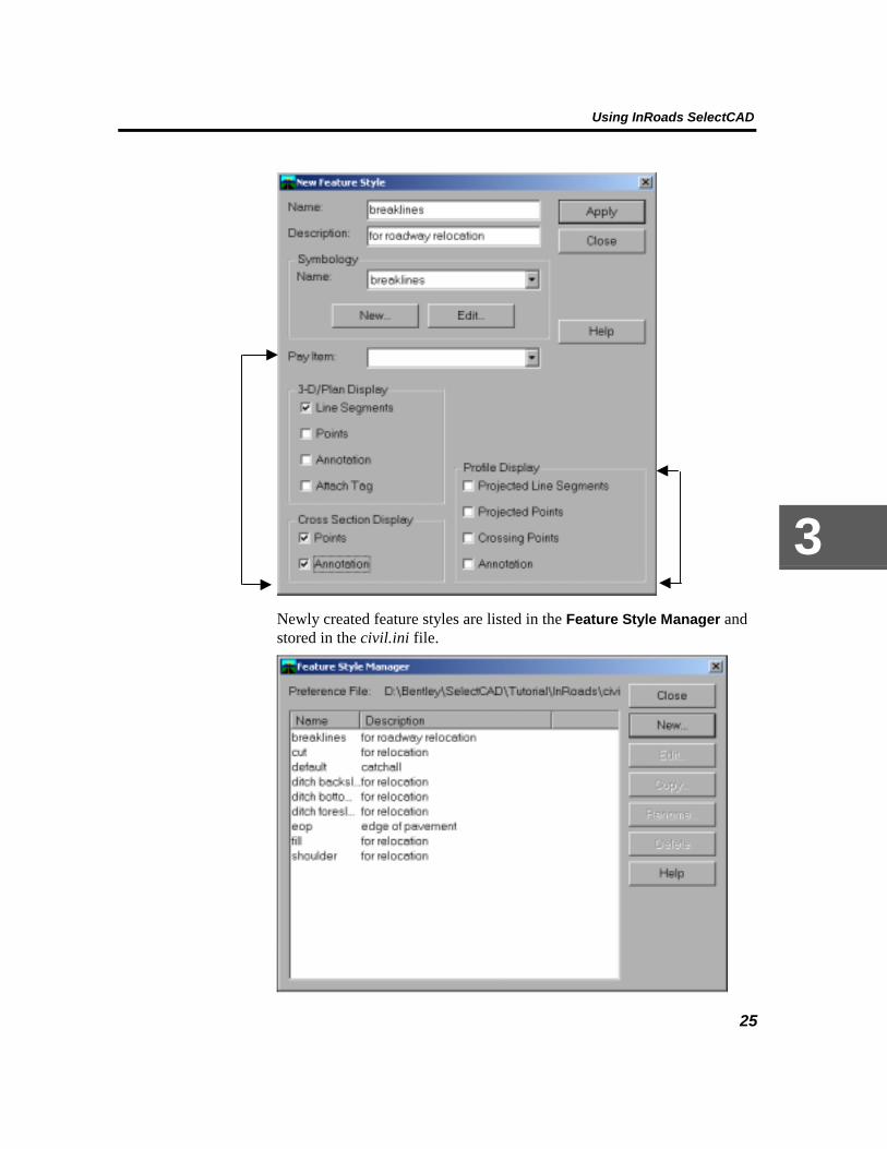
Optionally, you can type more details about the feature style in the Pay Item field and specify how the feature is to be represented in the graphic view (as a line segment, point, annotation or attached tag). For example, to see the features using this style displayed in cross section, turn on Points in the Cross Section Display section.
Using InRoads SelectCAD
25
3
Newly created feature styles are listed in the Feature Style Manager and stored in the civil.ini file.

Working with InRoads SelectCAD
26
Feature styles can be created or modified from any of the Style buttons that appear on most Surface > Design Surface commands.
View Surface Features Features that are a part of the active surface can be displayed for review. To see the features, use the Surface > View Surface > Features command.

Using InRoads SelectCAD
27
3 After choosing a surface, you can select individual features from the list, select all of the features or click Filter to build a feature selection set to view.

Working with InRoads SelectCAD
28
Viewing Surface Features using the Feature Selection Filter
The Filter option on the View Feature dialog box is a shortcut to the Surface > Feature > Feature Selection Filter command. This command allows you to quickly specify a feature selection set.

Using InRoads SelectCAD
29
3
By clicking Save As, the filtered selection-set can be saved and associated with a name for future reference.

Working with InRoads SelectCAD
30
Note: Before OK is applied, make sure the Feature Filter Lock is on. If the filter lock is not on, filters are not applied. Turn on this lock by clicking Tools > Locks > Feature Filter Lock.

Using InRoads SelectCAD
31
3
When you click OK, selected features are listed in the View Features dialog box. When you click Apply, these features are displayed.
Once features are in the surface, you can display and modify feature properties.
Feature Properties The Surface > Feature > Feature Properties command allows you to edit feature properties. Use this command to change the feature name, modify the description or style, and set the criteria for triangulation. You can take action against all features in the surface, against a filtered feature-selection set, or against selected features.

Working with InRoads SelectCAD
32
Once features are defined or modified and displayed, you can annotate them within the design file.
Annotating Features The Surface > View Surface > Annotate Feature command allows you to annotate features within the DTM.

Using InRoads SelectCAD
33
3
Click Apply to display the annotation.

Working with InRoads SelectCAD
34
Preferences Preferences allow you to define everything from general operating parameters (like units of measure, decimal places to display, stationing format, and symbology) to specific instructions as to which settings apply to a particular design surface. In InRoads SelectCAD, preferences are now a flexible system that could be considered as a single group of information that is simply defined in four different ways:
Preferences
BasicPreferences
PreferenceManager
SurfacePreferences
PreferredPreferences
Basic Preferences Basic preferences are settings that are defined at the command level. These values are set on the individual command dialog box located on most InRoads SelectCAD menus.
Basic preferences govern general operating parameters such as units of measure, stationing format, decimal places, local symbology, and so on.

Using InRoads SelectCAD
35
3
Settings that have been selected across the various tab options can all be saved to a preference set. Preferences are stored in the civil.ini file. When you want these configured settings for a particular design session, you can load the saved file from the Preferences dialog box. At start up, all available preference files currently in the civil.ini are listed here:

Working with InRoads SelectCAD
36
You can create or modify basic preferences at any time from the Preferences dialog box.
Preference Manager You could set basic preferences for every command under each InRoads SelectCAD menu, as previously mentioned:
Or, you could globally set all of these values (in addition to other detailed settings required by some commands) in one place at one time, using the Tools > Preference Manager command. Previously known as the Preference Editor, Preference Manager now acts as the global editor that allows you to specify preferences across InRoads SelectCAD.

Using InRoads SelectCAD
37
3
In Preference Manager, begin by entering a Preference name. Here, you could type a unique name for a new preference set, or you could select an existing preference set from the list (any setting change will modify the set).

Working with InRoads SelectCAD
38
Notice that in the Status field, it is indicated whether or not a preference object has already been defined for this preference set (either at the command dialog box or in Symbology Manager). If initialized is displayed, preferences for the object have already been defined; however, you can modify the settings here and associate them with the new preference set. This is helpful if you want to standardize preferences across a design session or meet a specialized customer deliverable.
To set preferences, double-click on an object (or select it and click Edit).
Individually set each value for an object:

Using InRoads SelectCAD
39
3
Or, you can select a named symbology. If you choose a named symbology, the values previously defined in Symbology Manager populate the dialog box:
You must individually save each object preference.
When you have selected and saved all of the preferences, click Close to dismiss Preference Manager:

Working with InRoads SelectCAD
40
Named preferences are saved and stored in the civil.ini file.
Surface Preference A surface preference is a named preference that you want to associate with a surface. When a preference is associated with a surface, all of the settings and display characteristics that were previously defined will be active for the surface.
Note: The Tools > Locks > Style command must be on. If Style Lock is not on, the basic preferences from the command dialog box will apply.
A surface preference can be specified when creating a surface with the File > New > Surface command.

Using InRoads SelectCAD
41
3
In addition, you can change surface preferences at any time during a design session using the Surface > Surface Properties command.
If, during a design session, you choose a different surface preference, use the Surface > Update 3-D/Plan Surface Display command to refresh the graphic display with the new preferences.
Preferred Preference The preferred preference is the default global preference set. At start up, the preferred preference is the system Default (these are selected settings delivered with InRoads SelectCAD). If you have created a named preference set and desire to have it as the default, access the Tools > Options > General tab. For Category, select Settings.

Working with InRoads SelectCAD
42
When specifying a preferred preference, if the Refresh Command Settings on Preference Change toggle is on, all of the InRoads SelectCAD commands that are affected by the preference change are updated to reflect the new preference settings. If a command dialog box does not have a named preference corresponding to the preferred preference, the system defaults continue to apply for that dialog box.

Using InRoads SelectCAD
43
3
Click Apply to activate the preferred preference.

Working with InRoads SelectCAD
44
Locks In InRoads SelectCAD, there are several lock features that work together with Symbology Manager, Preference Manager, and Feature Style Manager to streamline your required interaction with the software.
For quick access to the lock commands, select Tools > Locks > Toolbar:
Feature Filter Lock The Feature Filter lock works in conjunction with the Surface > Feature > Feature Selection Filter command to automatically make available a filtered feature-selection set. When a selection set is created using the Feature Selection Filter command, it is given a name for future use.

Using InRoads SelectCAD
45
3
Not only is the feature-selection set saved to the civil.ini file, the name assigned to the set is listed in the Feature Filter List located on the Locks toolbar.
When the Feature Filter toggle is turned on, these selection sets are now exclusively available for display without any further interaction with the Feature Selection Filter command dialog box.

Working with InRoads SelectCAD
46
Subsequently, when the Surface > View Surface > Features command is selected, only those feature types specified in the selection set are available for display.
Click Apply to display the features in the surface. Or, you could use the Locate button to identify features (of the filtered type) by datapoint in the surface.
Note: When the Feature Filter lock is off, defined feature selection sets are not available or applied.
Style Lock The Style lock works together with Preferences, Preference Manager and Feature Style Manager to automatically display global preference settings and defined features styles. As previously detailed, preference settings are defined at the local command dialog box or globally in the Preference Manager.

Using InRoads SelectCAD
47
3
Feature styles are created and named using the Tools > Feature Style Manager > New command, and are listed in Feature Manager.
Once preferences and feature styles have been defined, you can turn on the Style lock toggle to have these settings automatically display during the design session, without any further interaction with command dialog boxes.
When the Style lock is on and a command is selected, data preferences are active and displayed; no dialog box is presented. When Style lock is off, each time a command is selected a dialog box is presented allowing you to define display preference and style.

Working with InRoads SelectCAD
48
This command allows you to reduce required interaction with InRoads SelectCAD commands.
Write Lock The Write lock generates graphics in one of two modes: display and write or display only.
During a design session, when the Write lock toggle is on, graphics created by each command are displayed in the CAD views and are written to the active design/drawing file. In this mode, you can use any of the CAD windowing functions to access a different view of the data, or the editing commands to modify the data.
During a design session, when Write lock is toggled off, all graphics are generated in the display-only mode. This means the generated graphics are only displayed in one or more CAD views, but are not written to the active design/drawing file. In this mode, using any of the CAD windowing commands will remove the graphics from the view because the elements have not been written to the design file. In addition, because the elements do not actually exist in the active design/drawing file, you can not edit or modify display-only graphics.
Designing with Write lock off is useful when you need to view large amounts of terrain model data and then quickly remove that data from the screen. Since the display-only mode does not write graphics to the active design/drawing file, you can decrease design file size and increase the speed in which all graphics display in the CAD views using this mode.
In InRoads SelectCAD, version 8.2, Write lock works in conjunction with the Pencil/Pen mode. When Write lock is toggled on, it activates the additional Pencil/Pen mode.
Pencil/Pen Mode When graphics are generated and written to the design/drawing file, the Pencil/Pen mode is available. These modes are an enhancement to the Write lock feature in that they allow you to write to the design/drawing

Using InRoads SelectCAD
49
3
file in either temporary or permanent form. This idea is similar to drawing on a sheet of paper with pen or pencil. When writing in pencil, you can quickly erase a drawing to remove it. In contrast, writing in ink (pen) is a more permanent form that must be deleted to be removed. Similarly, in InRoads SelectCAD graphics written in pencil are not retained between iterations of display, and graphics written in ink are retained each time the object is displayed.
For example, if you turn on Pencil mode and select the InRoads SelectCAD Surface > View Surface > Perimeter command, the graphic is displayed and written to the CAD design/drawing file.
Then, using a CAD manipulation command, such as Move you relocate the graphic. Next, select Surface > View Surface > Perimeter to display it again. The previous graphic is “erased” and only the most recent graphic appears.
Note: The Pencil/Pen mode that is active when the graphic is initially displayed determines whether or not it is erased when it is redisplayed.

Working with InRoads SelectCAD
50
Graphics written in Pencil mode are retained only until the next time the same graphic is selected for display.
Note: During a design session in Pencil mode, there may be an occasion where you do not want pencil graphics to automatically be erased. To override this action, select the Tools > Options > General tab. For Category, select Settings and turn on the Omit Automatic Graphics Refresh toggle. All graphics, written in pencil or ink, will be retained until you manually delete them.
In contrast, if in Pen mode you select Surface > View Perimeter, the graphic is displayed and written to the design/drawing file.

Using InRoads SelectCAD
51
3
Then, using the CAD Move command, you relocate the graphic. Next, select Surface > View Surface > Perimeter again. Both graphics appear. The first is retained because it was written in ink, the second appears because it is the most recent.
All graphics written in Pen mode are retained until they are deleted. Graphics can be manually removed using the CAD Delete command or by activating the InRoads SelectCAD Delete Ink lock.
Delete Ink Lock The Delete Ink lock is available when Write lock is on. Turn on this toggle to quickly remove all graphics that were previously written in ink.
For example, if you have three iterations of a graphic that was written in ink, all three graphics appear in the design/drawing file.

Working with InRoads SelectCAD
52
Then, if you turn on the Delete Ink lock and select the command again, only the current graphic is displayed.
All of the previously displayed graphics are deleted. To override the Delete Ink lock, select the Tools > Options > General tab. For Category, select Settings and turn on the Omit Automatic Graphics Refresh toggle. All graphics, written in pencil or ink, will be retained until you manually delete them.

Using InRoads SelectCAD
53
3
Locate Graphics/Features During an InRoads SelectCAD design session, you create, edit and manipulate objects in two different environments: the CAD design/drawing file and the DTM model surface. Objects located in the CAD design/drawing file are referred to as graphics. Objects located in the DTM model (design surface) are referred to as features. The Locate Graphics/Locate Features mode lets you quickly specify the environment from which to select objects.
For example, if you toggle to Locate Graphics and select the Surface > Design Surface > Set Elevation command for a Single graphic element, you are prompted to identify an element within the CAD design/drawing file.
While remaining in the same command dialog box, you can toggle the mode to Locate Features.

Working with InRoads SelectCAD
54
The dialog box options dynamically change. You can now identify features in the surface.
Identify and locate individual features or select all available features in the surface.
Note: While an alignment (*.alg) is another way to manipulate objects during a design session, the geometry data in the alignment is not accessible from the Locate Graphics/Locate Features command.
Point/Element/No Snap Lock This lock is a three-way toggle that allows you to specify the snap mode when working with feature and geometry data.
• Point Snap. This lock allows you to snap onto any point contained in the geometry project. This mode is helpful when placing geometry
Using InRoads SelectCAD
55
3
elements. For example, if you want to input point data into a dialog box, toggle this lock on and place a data point in the design file. InRoads SelectCAD will find the closest point and display the point data in the dialog box.
• Element Snap. This lock allows you to snap or lock onto any geometry element (any object that would require multiple data points to define) in the geometry project. This mode is helpful when using the direction, distance, length, radius, and/or angle of an existing geometry element to design a new element. When this lock is on, InRoads SelectCAD snaps to the element nearest the data point you place in the design file
• No Snap. This mode disables both point and element snap.
Station Lock This on/off lock is applicable only when the first station specified on the horizontal alignment is an odd-numbered station (for example, 2+39) and you are generating cross sections, executing the roadway modeler, or generating station type reports. When this lock is turned on, InRoads SelectCAD applies a given command action to the first station, and then forces all subsequent actions to even-numbered stations. For example, if the first station 2+39 and the station interval is defined as 50, InRoads SelectCAD performs the command action at stations 2+39, 2+50, 3+00, and so on. When the Station lock is turned off and the first station is odd-numbered, InRoads SelectCAD applies the command action to odd-numbered stations only (for example, 2+39, 2+89, 3+39) and so on.
Report Lock This on/off lock is used by several commands to control whether or not the output displays in a dialog box as the command calculations are performed. If this lock is off, the command processes and stores results without displaying them in an output dialog box.

Working with InRoads SelectCAD
56
General InRoads SelectCAD Review While InRoads SelectCAD includes expanded functionality in several areas, many of the software’s standard features remain.
Comprehensive Data Structure The data structure for InRoads SelectCAD remains much more comprehensive than those of the CAD platforms on which it runs. It accommodates the intelligence needed to perform sophisticated 3-D design operations such as earthwork analysis, profile generation, and superelevation. Its ability to maintain double-precision numbers is not dependent upon the CAD platform. As you place or locate design elements or coordinate geometry points, InRoads SelectCAD tools accommodate double-precision input. Even graphical selection tools automatically snap to points and elements in your geometry project with double-precision accuracy.
Horizontal and Vertical Alignments Alignments continue to represent longitudinal features, such as centerlines, lanes, access ramps, and ditch grade lines. The horizontal and vertical geometry of an alignment is designed separately, with the vertical being a child of the horizontal. There are no restrictions on how many vertical alignments you can attach to a horizontal alignment. Alignments are designed using the geometry component of InRoads SelectCAD, which has an array of features for locating points and designing the curvilinear geometry through them.
InRoads SelectCAD automates the creation of horizontal and vertical geometry. In the initial design phase, you can use a backdrop of graphics such as a DTM, aerial photo, MicroStation graphics, and so forth. You can define curve and tangents, in any order, with or without automatic spiral placement, and if you need to add spirals, you can do so as you define the circular curves. See Chapter 5, Learning InRoads SelectCAD for detailed instructions.
When the rough geometry is complete, you can begin to refine the alignment. You can dynamically manipulate elements or use precision key-ins. The software provides immediate visual feedback and automatically adjusts the geometry throughout the alignment, maintaining coincidence and colinearity between all the elements where appropriate.

Using InRoads SelectCAD
57
3
Typical Sections Typical sections remain one of the most powerful features of InRoads SelectCAD’ corridor design capabilities. Contrasted with alignments, which represent longitudinal geometry, typical sections represent transverse geometry. Typical sections consist of templates, which are the backbone of your road design, and various tables that can be used to create the side slopes. Templates can be fixed or controlled by horizontal and/or vertical geometry by using simple offsets.
When typical sections are paired with horizontal and vertical alignments and superelevation, they define the surface of a corridor. Typical sections are flexible design components--as easily applied to ditches and sidewalks as to multilane highways with superelevated curves and variable side slopes.
Side Slopes Side slopes, representing embankments and cuttings between a corridor surface and the original ground, can be designed with any of four methods provided by InRoads SelectCAD:
• Decision table
• Cut/Fill table
• Material table
• Template
The decision table method encompasses almost all the functionality of the other three methods. Whether your design is simple (one slope up/one slope down) or requires toe-of-slope ditches or noise berms, the decision table method provides a high degree of flexibility, with tight control over the placement of side slopes. You can set up decision tables not only to define multiple intersections with design surfaces, but also to adjust those surfaces (for topsoil stripping, for example) and to recognize and attach to independent horizontal and vertical alignments.
InRoads SelectCAD includes three other methods that provide subsets of the functionality in decision tables. The template method extends the template beyond the backbone (hinge points) based on the cut and fill slopes you define. Side-slope intercepts for sublayers are defined exclusively with the template method. The cut/fill table method allows a straightforward selection from a series of slopes depending on which one hits original ground. If you want to vary the side slope in cut, strictly according to the material you are cutting through, you can use a material table to determine the appropriate slope. Both cut/fill and material

Working with InRoads SelectCAD
58
methods have capabilities to automatically design ditches or shoulders as required. Both can also add benches, either at fixed intervals from the road or at constant elevations.
Evaluation InRoads SelectCAD continues to provide tools to make preliminary evaluation of your model quick and simple. These tools allow you to do the following:
• Display triangles and slope vectors and view them from any angle.
• Produce contours, cross sections, and profiles to compare original surfaces with design surfaces.
• Compute volumes using the triangle, grid, or end-area method.
• Produce Mass-Haul diagrams.
Superelevation Superelevation relates to the banking applied to offset the lateral acceleration that vehicles experience when going around curves. More specifically, it is the transverse slope between the inner and outer edges of a banked curve. InRoads SelectCAD continues to accommodate all commonly used methods of calculating superelevation rates, including the five AASHTO methods and numerous international methods. Plus, InRoads SelectCAD gives you control over how superelevation is achieved longitudinally along an alignment, with parametric control over transition lengths and methods of transition.
The Roadway Model Roadway Modeler pulls together all of your design data to create the corridor model. The modeler uses a roadway definition to place appropriate templates and side slopes at intervals and at critical design points along the alignment. In addition, it applies superelevation and adjusts the templates to the longitudinal features as necessary, as well as checks right-of-way limits. The end result of this is a DTM for each of the layers in the proposed corridor surface. These layers are comprised of 3-D linear features and xyz random points, providing a full 3-D model of the proposed roadway. The model features can then be displayed in the CAD design/drawing file.
For simple projects, InRoads SelectCAD provides Express Modeler, which produces a model quickly, with only minimal information. You only need to provide an existing surface, a horizontal alignment, and a

Using InRoads SelectCAD
59
3
single template. If you wish, you can also provide a vertical alignment, but InRoads SelectCAD will use elevations derived from a horizontal alignment if no vertical alignment is provided.
Drawing Production Plan and profile drawings can now be easily generated from InRoads SelectCAD graphics. You can create construction documents, such as plan/profile, cross sections, and detail sheets.
Reports Reporting in InRoads SelectCAD is flexible and comprehensive. You can produce reports on any data that you have created or manipulated in the course of a project. Such reports might include listings of coordinate geometry points, alignment clearances, and earthwork data. InRoads SelectCAD also allows you to track your design activities. You can save your activities as report files or append them to other report files; they are invaluable for project documentation. All reports are generated in ASCII format for easy manipulation in a text editor or word processing program.
Visualization Designs produced with InRoads SelectCAD can be used with visualization software to create photo-realistic images, which help your project team or client better visualize the design. Bentley Systems also complements InRoads SelectCAD with a range of applications for editing and manipulating images to create photomontages or video presentations. These capabilities help you prepare presentations for non-technical audiences.

Working with InRoads SelectCAD
60
Getting Around in InRoads SelectCAD
Using the Interface InRoads SelectCAD utilizes the Windows Explorer environment for file management. It works like the Explorer in the Microsoft Windows environment. By either clicking the plus sign (+) in the square next to an item or double-clicking on the name, a subgroup of items displays just like a directory tree. The SelectCAD Explorer provides a quick view of files that have been loaded and are available in a working session.
From the InRoads SelectCAD Explorer, you can “tear away” the left-pane Explorer tree, now referred to as the Workspace Bar:
There are several unique advantages of the Workspace Bar. First, major objects are represented by tabs at the bottom of the view. Each tab corresponds to a particular view of the overall SelectCAD hierarchy. Second, by clicking a tab, such as the Surfaces, you’ll see all (and only) the surface objects in the project.
Workspace Bar’s can be docked anywhere on the screen for easy access:

Using InRoads SelectCAD
61
3
To return the Workspace Bar back to the Explorer, click and drag the box to the desired location:
Once you are in SelectCAD, you can drag and drop your InRoads SelectCAD data directly from the Windows Explorer. The status of the data is displayed in the bottom portion of SelectCAD window.

Working with InRoads SelectCAD
62
In the SelectCAD Explorer, you can access additional options that are available for an entity. For example, if you select (highlight) a surface and right-mouse click, a pop-up menu appears with additional options for surfaces.
The additional options that are available depend on the entity that you select. In the SelectCAD Explorer, you can also access to the following shortcuts:
• Press the Insert key to activate the New dialog box.
• Press the Delete key to delete the current item.
• Drag-and-drop features between surfaces.
• Click an item to rename it.
• Hold down the Shift key to display all the points in a feature, not just the first hundred.

Using InRoads SelectCAD
63
3
• Review file revision data.
• Cut and paste between fields.
• Click File > Open then, right-mouse click to edit ASCII files, using the default text editor. For example, to open and InRoads SelectCAD project file:
Review the right-mouse click menu for additional file and mailing options.

Working with InRoads SelectCAD
64
The SelectCAD Explorer can be moved to a convenient location on the screen and make several common tasks faster and easier.
Accepting/Rejecting Solutions If MicroStation is your CAD platform and you are using the default mouse configuration, you accept an InRoads SelectCAD solution by clicking the

Using InRoads SelectCAD
65
3
left mouse button. You reject an InRoads SelectCAD solution by clicking the right mouse button.
If AutoCAD or is your CAD platform, you accept an InRoads SelectCAD solution by clicking the right mouse button, by typing accept or a, or by pressing Enter. You reject an InRoads SelectCAD solution by typing reject or r.
On both CAD platforms, you exit an InRoads SelectCAD command by pressing Esc.
Using Access Control Access control allows you to share files among multiple users while controlling read-write access to the data. Using access control, you can essentially “lock” your data so that another user cannot overwrite it while you are working on it. The other user can open the data (read-only access) but cannot make changes to it while you have it opened with read-write access. Likewise, if another user has some data opened with read-write access, your only option is to open the data with read-only access.
Access control works with individual horizontal alignments, the cogo buffer, and preference files. However, with preference files, you lock the entire file−not individual preferences. When you have read-write access to a horizontal alignment, you also have read-write access to all data associated with the horizontal alignment: vertical alignments, superelevations, vertical event buffers, and horizontal event buffers.
To set the access status, right-mouse click the horizontal alignment, cogo buffer, or preference file in SelectCAD Explorer. When the menu appears, select either Read-Write or Read-Only. The status is reflected in SelectCAD Explorer.
For more information about access control, see the SelectCAD Help.

Working with InRoads SelectCAD
66
Menus The SelectCAD Explorer contains menus that are the primary source of interaction with InRoads SelectCAD.

Using InRoads SelectCAD
67
3
The menu titles are intuitive to a function of the design process. They help
you navigate to groups of commands used for a specific task. A small right arrow by a command indicates an additional menu with commands.
Menus and Application Add-Ins InRoads SelectCAD is delivered with several additional software modules that allow you to complete specialized or advanced tasks, including data translation. To access these features, select Tools > Application Add Ins.
By default, these additional commands do not appear on InRoads SelectCAD menus because they are “turned off”. However, when you select add-in applications, menus are dynamically updated and the commands are listed on the appropriate menu. For example, by default the Geometry menu does not include the Horizontal and Vertical Element Add-In. If you select it to turn it on and click Apply, the command is dynamically added to the menu:

Working with InRoads SelectCAD
68
Add-in applications can be turned on and off at anytime during a design session.
Customize Menus You can also create customized InRoads SelectCAD menus using the Tools > Customize >Command tab.

Using InRoads SelectCAD
69
3
This command allows you to group specific commands together on a menu. First, select the menu on which to place the commands.
Then, drop and drag the selected command onto the menu.
The command is added to the menu.
Customize Toolbars With the Tools > Customize > Toolbars command, you can select predefined toolbars to display that provide quick access to frequently used commands. There are toolbars for specific groups of menu commands, such as View Surface.

Working with InRoads SelectCAD
70
Note: Notice that the Fit Surface command is on the toolbar but not on this particular pull-menu. The command is added here for convenience: once you display various representations of the surface, you can quickly fit the surface in the view.
Perimeter
Triangles
Contours
Label Contours
Features
Annotate Features
Elevations
Single Point Elevation
Slope Vectors
Single Slope Vector
Two Point Slope
Crossing Segments
Inferred Breaklines
Profiled Model
Gridded Model
Color-Coded Aspects
Color-Coded Elevations
Color-Coded Slopes
Update Surface Display
Fit Surface

Using InRoads SelectCAD
71
3
There are also predefined toolbars for common design workflows. The commands on the workflow toolbars may not appear together on any one menu or all of the available commands may not appear, but several are grouped together on the toolbar for a specific function. For example, Design Roadway.
If a predefined toolbar does not meet your design needs, you can create customized toolbars for unique workflows. Select Tools > Customize > Toolbars > New.
Click the Commands tab. Select commands from the list to drag and drop onto the toolbar.
Define Typical Sections
Define Roadway
Copy Typical Section
Roadway Modeler
Express Roadway Modeler

Working with InRoads SelectCAD
72
With customized toolbars, you can step through the design process from surface creation to plan and profile sheet generation using a single toolbar.
Once toolbars are displayed, they can be moved to a convenient location on the screen or they can be “docked” onto the SelectCAD Explorer. To dock a toolbar, click and hold on the toolbar, drag it to the SelectCAD Explorer and release it.

Using InRoads SelectCAD
73
3
Docked toolbars remain in the SelectCAD Explorer until you delete them.
To remove a docked toolbar, click on it and drag it away from the SelectCAD Explorer and click the X button. Or, to remove all customized toolbars and menus, click Tools > Customize > Toolbars > Reset All.
Shortcut Keys to InRoads SelectCAD Commands Use the Tools > Customize > Keyboard tab to create new keystrokes to activate InRoads SelectCAD commands.
You can create new shortcut keys or modify existing ones.

Working with InRoads SelectCAD
74
Customize Macros The Text > Customize > Macros command provides access to external software programs that can be run within InRoads SelectCAD. For example, you can click New to create a macro to run Notepad®, a Microsoft text editor, in a specific directory.
Click Browse to locate the Notepad executable. This automatically populates the command field. Then, specify the Argument (file on which to run the editor) and the initial directory (where the file is located).
Click Close. Now, the new macro appears in the Commands list. You can then drag and drop the new macro onto a toolbar or menu.
The Button Appearance dialog box appears. Select an icon to represent the macro.

Using InRoads SelectCAD
75
3
The icon appears on the toolbar. Now, double-click the icon to start the command.
You can also use the Tools > Customize > Macros command to run advanced software programs created using the InRoads SelectCAD Application Programming Interface (APIs). APIs give you direct access to the InRoads SelectCAD alignment and surface data. See SelectCAD Help for more information on customizing InRoads SelectCAD with APIs.
Exporting Custom Settings Once custom menus, toolbars and command-shortcut keys have been created, you can save all of the settings to a file for use in future design sessions. To access this command, select Tools > Customize > Export.

Working with InRoads SelectCAD
76
• Full Export – Use this option to save all custom settings.
• Partial Export – Turn on this option to individually choose which toolbars to save. You may also specify shortkeys, macros or both.
Importing Custom Settings Previously defined settings can be imported for a current design session. To access these settings, select Tools > Customize > Import.
Click Browse to locate the settings file.

Using InRoads SelectCAD
77
3
Using the Online Help System To display Help when InRoads SelectCAD is active, click Help > Contents from the main menu.
SelectCAD Help Topics InRoads SelectCAD is delivered with comprehensive online reference information for each command. This information is available through the InRoads SelectCAD Help system. The Help topics include a brief

Working with InRoads SelectCAD
78
overview of the command, a detailed description of the dialog box options, and a step-by-step workflow that shows how to use the command.
InRoads SelectCAD allows you to design while integrated with other SelectCAD applications. In this environment, you can access the online Help topics for these applications in addition to InRoads SelectCAD Help.
Note: If Help was not installed on your hard drive during setup, you must have the InRoads SelectCAD CD in the CD-ROM drive or be connected to the network node containing the Help files.
! Click the Contents tab to display the Contents page for InRoads SelectCAD Help. This page is similar to a table of contents in that it lists everything that is available in the Help files. Double-click a file to display it. After reviewing a topic, you can close it or print it.
! Click the Index tab to enter a command name, phrase, or word for which to search. This page is similar to a book index with items listed in alphabetical order. As you type a word, the list dynamically updates as the sorting feature narrows the search. Double-click the topic when it appears in the list, or click the Display button.
! Click the Find tab to access a full-text retrieval search. Full-text retrieval allows you to search for specific words instead of alphabetized categories. First, the software builds a database of words from all available Help files. Once the database is compiled, you can search it for any key word. A workflow wizard steps you through this brief process. Double-click a located word or click the Display button to display the search results.
To display SelectCAD Help outside of the product, from the Start menu, click Programs > Bentley Civil Engineering > Civil SelectCAD Suite Help>.
SelectCAD Help is context sensitive, which means that you can press F1 to display Help for the active command or dialog box. You can also click the Help button on each dialog box.

79
4
Looking at InRoads SelectCAD Workflows
The following workflows represent typical paths you might take when designing a civilworks project using InRoads SelectCAD. Your particular workflow may vary depending on the needs of your project.
Master Workflow This workflow diagram presents a few of the paths that you could take through the application to finish your project.
Create and editvertical alignments Extract profiles
Start InRoads and opena design/drawing file
Create and edittypical sections
Create a surface
Open a project
Create and edit ahorizontal alignment
Review designsurface
Extract crosssections
Compute cut andfill volumes Create reports
Run RoadwayModeler
Define side slopes Define roadway
Calculatesuperelevations
4

Working with InRoads SelectCAD
80
Creating an Overall Project The following diagram illustrates a general workflow for creating overall InRoads SelectCAD projects.
Open a styles file Open apreferences file
Open/create ageometry file
Open/create a typicalsection library
Open/create aroadway library
Open/create asurface
Select "Save AsProject" command
Set the project optionsand click "Apply"
Creating a Surface The following diagram illustrates a general workflow for creating surfaces.
View the surface
Import surfacedata
Triangulate thesurface
Create a surfaceslot
Save the surface

Looking at InRoads SelectCAD Workflows
81
4
Creating or Editing Geometry Projects and Associated Horizontal Alignments
The following diagram illustrates a general workflow for creating and editing geometry projects and their associated horizontal alignments.
Save geometry Display alignments Edit alignments
Create/open a newgeometry project
Import alignmentdata
Create horizontalalignments
Import/createCogo points
Cogo alignmentcommands
Locate commands
Extracting Profiles The following diagram illustrates a general workflow for extracting profile information from your horizontal alignment. This is an optional task if you are using the vertical alignment editor.
Select the "CreateProfile" command
Set parametersas needed
Plot the profile
Set the desiredactive alignment

Working with InRoads SelectCAD
82
Creating or Editing Vertical Alignments The following diagram illustrates a general workflow for creating and editing vertical alignments.
Save the geometry Display thevertical alignment
Set the activehorizontal alignment
Create a verticalalignment slot
Importalignment data
Edit the verticalalignment
Creating or Editing Typical Sections The following diagram illustrates a general workflow for creating or editing roadway templates. This is an optional task. You could also use the surface design, cross section editing, or import geometry to surface commands with similar results.
Create a typicalsection library
Load a typicalsection library Copy a template
Add a template
Edit template
Set transitioncontrol
Add/edit templatesegments
Select/addactive layer
Set superelevation Save the typicalsection library

Looking at InRoads SelectCAD Workflows
83
4
Defining Side Slopes InRoads SelectCAD defines side slopes several ways.
Cut and fill tables
Typical Sections Material tables
Decision tables
Defining Side Slopes with Cut/Fill Tables
The following diagram illustrates a general workflow for defining side slopes by using cut/fill tables.
Add a newcut/fill table
Copy an existingcut/fill table
Edit cut/fill table Add/edittable entries
Save the typicalsection library
Defining Side Slopes with Material Tables The following diagram illustrates a general workflow for defining side slopes by using material tables.
Add a newmaterial table
Copy an existingmaterial table
Edit material table Add/edittable entries
Save the typicalsection library

Working with InRoads SelectCAD
84
Defining Side Slopes with Decision Tables
The following diagram illustrates a general workflow for defining side slopes by using decision tables.
Add a newdecision table
Copy an existingdecision table
Edit decision table Add/edittable entries
Save the typicalsection library
Creating and Calculating Superelevations
The following diagram illustrates a general workflow for defining superelevations. This is an optional task.
Build super-elevation transitions
Review/edit super-elevation values
Set active horiz.and vert. alignments Define roadway Create a super-
elevation slot
Compute super-elevation rate
Save thegeometry project

Looking at InRoads SelectCAD Workflows
85
4
Defining the Roadway The following diagram illustrates a general workflow for defining roadways.
Set right-of-waycontrols
Save the roadwaylibrary
Load a roadwaylibrary
Copy an existingroadway
Add a roadway
Edit roadways
Set horiziontal andvertical controls
Add/edit roadwayentries
Running the Roadway Modeler The following diagram illustrates a general workflow for modeling the roadway.
Load geometry Load applicablesurfaces
Load applicabletypical section lib.
Run roadwaymodeler
Load applicableroadway library
Reviewing the Design Surface The following diagram illustrates a general workflow for reviewing the design surface.
Review surfaces View surfaces

Working with InRoads SelectCAD
86
Extracting Cross Sections The following diagram illustrates a general workflow for extracting cross sections from the roadway.
Data point forgraphic location
Load geometry Load surfaces Select the "CrossSection" command
Click "Apply" Set parameters asnecessary
Computing Volumes InRoads SelectCAD calculates volumes in three ways.
Triangle volumeEnd area volume Grid volume
Creating Reports The following diagram illustrates a general workflow for creating reports.

Looking at InRoads SelectCAD Workflows
87
4
Geometry: Setother parameters
General: Definebinary input file
Select report format
Reports
General
Geometry
Bridge
Select report type
Specify output
Select report library

Working with InRoads SelectCAD
88

89
5
Learning InRoads SelectCAD
This chapter contains lessons that provide a brief look at creating a roadway using InRoads SelectCAD. The workflow represents a typical approach to roadway design and gives you a practical application of some of the more commonly used commands in the product.
It is recommended that you start at the beginning of the tutorial and work through to the final lesson. However, you can complete the lessons individually, in any order.
While the lesson demonstrates how to accomplish an entire road design, it is not meant to be a comprehensive discussion of every possible command and parameter within the product. For more details on a specific command or concept in the lesson, see the SelectCAD Help Topics (click Help > Contents or press F1).
Prerequisites Before you start, you should already know how to run your CAD software. If you are a new user, it is recommended that you read the introductory chapters of this document to gain a general understanding of the software. If you are an experienced InRoads SelectCAD user, you may want to review the introductory chapters, as there are many changes in this version of the software.
InRoads SelectCAD must be successfully installed and running on your machine. The tutorial files are downloaded during Setup with a Typical installation. The files are stored in the C:\Bentley \SelectCAD\Tutorial\InRoads directory.
Note: It is assumed that you installed InRoads SelectCAD to the C drive and default directory path. If you installed the product on a different drive or directory path, the location of the files is different than those in the lessons.
5

Working with InRoads SelectCAD
90
Saving Your Work Throughout the lesson, you will load files from and save files to the \Tutorial\InRoads directory. However, you can create another directory and save your files there. If, in the lesson, the instructions tell you to load a file that you created or modified, you can load the file from your directory.
Before Starting Each Lesson Before starting each lesson, you must first extract the lesson files. To extract the files, do the following:
1. From the Start menu, click Programs > Windows NT Explorer if you are running Windows NT, or Programs > Windows Explorer if you are running Windows 98 or Windows 2000.
2. Set the directory to C:\Bentley\SelectCAD\Tutorial\InRoads (or to the appropriate directory if you copied the files).
3. The self-extracting tutorial files are named roadlesson1.exe, roadlesson2.exe, and so on. Double-click the file that corresponds to the lesson that you are on. For example, double-click roadlesson3.exe to extract the files for Lesson 3.
Note: If you have already extracted the files for a previous lesson, you may be prompted to overwrite some files. To overwrite these files, type Y at the prompts.
If you start the lesson and see that you have done something wrong, you can exit the lesson, extract the files again, and start over using the new files that are provided. This lets you recover quickly from any problems that may occur as you manipulate your files.

Learning InRoads SelectCAD
91
5
Basic Roadway Design In this tutorial, you create a new roadway. You will complete the following tasks:
• Start the software.
• Set units of measure.
• Create a surface.
• Create a horizontal alignment.
• Create a profile along an alignment.
• Create a vertical alignment.
• Create plan sheets.
• Create a typical section.
• Create a decision table.
• Create a roadway library.
• Create a roadway model.
• Evaluate the design.
• Create reports.
• Create final plan and profile sheets.
Note: Depending on your CAD software, the graphical examples in the lesson may be different from what you experience. Where necessary, specific CAD instructions are provided.

Working with InRoads SelectCAD
92
Lesson 1: Starting InRoads SelectCAD Begin the design session by starting InRoads SelectCAD.
1. Extract roadlesson1.exe. For more information on extracting lesson files, see the Before Stating Each Lesson section at the beginning of this chapter.
2. Start InRoads SelectCAD. Click Start > Programs > Intergraph Civil Engineering > InRoads SelectCAD. On MicroStation, open road.dgn. On AutoCAD open road.dwg. These files are located in the Tutorial\InRoads directory.
Note: For MicroStation users only, the road_ref.dgn file that appears in this directory is a reference file for road.dgn. Open road.dgn
3. Click the Preferences tab at the bottom of the Explorer.
4. Click the plus sign (+) next to Preferences . Notice that there are two files listed. The civil.ini and wysiwyg.ini files were loaded when InRoads SelectCAD started.
5. To the right you should see three columns: File Name, Type, and Access Mode. The civil.ini file is labeled General and the wysiwyg.ini file is labeled Geometry.
6. Click the plus sign (+) next to Preferences in the SelectCAD Explorer. Notice that there are two files listed. The civil.ini and wysiwyg.ini files were loaded when InRoads SelectCAD started.

Learning InRoads SelectCAD
93
5
The General preference file sets units of measure (imperial or metric) and the settings and layers on which everything in the design, except the geometry, displays. The Geometry preference file determines how the horizontal alignment, coordinate geometry points, and closed figures would display. Next, you will modify the general preferences file.
Setting Units of Measure InRoads SelectCAD uses the units of measure selected during installation, either imperial or metric. This setting is saved in the civil.ini file. The location of the civil.ini is shown in the SelectCAD Explorer when you click Preferences. InRoads SelectCAD starts each session using this civil.ini file.
For this lesson, you will use metric units in a file prepared for this tutorial: civilm_tut.ini. To define settings, do the following:
1. Click File > Open.
2. Change Files of type to Preferences (*.ini).
3. Navigate to the C:\Bentley\SelectCAD\Tutorial\InRoads directory.
4. Select civilm_tut.ini and click Open.
5. Change Files of type to Styles (*.ini).
6. Select wysiwg.ini and click Open.
7. Click Cancel to dismiss the dialog box.
You have opened the preference files for metric settings. Next, set the units of measure within InRoads SelectCAD.
8. Click Tools > Options.
9. Click the Units and Format tab. Under Units, for Linear, select Metric. For Angular, select Degrees. Click Apply.

Working with InRoads SelectCAD
94
10. Click the Preferences button.
11. Click Save.

Learning InRoads SelectCAD
95
5
This updates the settings in the file. When you exit the product, the .ini file is saved so that next time you start InRoads SelectCAD the settings are the same.
12. Click Close to dismiss the Preferences dialog box.
You’ve just modified the civilm_tut.ini file.
13. Click Close to dismiss the Options dialog box.
14. Click File > Exit and then exit your CAD software, or continue to the next lesson.

Working with InRoads SelectCAD
96
Lesson 2: Digital Terrain Modeling InRoads SelectCAD uses DTMs as the basis for much of its engineering calculations. DTMs consist of a series of measured points connected together as triangles to form a 3-D faceted surface. In this lesson, you load points from a field survey, create a DTM, and display the surface perimeter, contours, and triangles.
One reason for modeling the existing terrain is to design the grade of your road using the existing terrain as a reference. When you are done designing the proposed road, you compare the roadway surface against the original surface to compute earthworks (volumes) for your design.
Before Getting Started If you did not exit InRoads SelectCAD and the CAD software in the previous lesson, skip to Creating a Surface. If you are just beginning the tutorial here, complete the following steps:
1. Extract roadlesson2.exe. For more information, see Before Starting Each Lesson at the beginning of this chapter.
2. Start InRoads SelectCAD, and open the road.dwg or road.dgn file. These files are located in the \Tutorial directory where you installed InRoads SelectCAD. For more details on starting the software, see Chapter 2, Starting InRoads SelectCAD.
3. Click File > Open.
4. Set the directory to C:\Bentley\SelectCAD\Tutorial\InRoads.
5. For Files of type, select Preferences (*.ini).
6. Select civilm_tut.ini, and click Open.
7. Change Files of type to Styles (*.ini)
8. Select wysiwyg.ini, and click Open.
These preference files contain default settings for this tutorial.
9. Click Cancel to dismiss the Open dialog box.
Creating a Surface The first step in your project is to create a model representing the existing ground in the project area. For this step, assume that a survey has already been made of the area. The data, in the form of xyz coordinates, has been put into two point files. Before you can load any surface information from these files, you must create a new surface to hold the data.

Learning InRoads SelectCAD
97
5
Note: A surface can be created in several ways, such as when importing a surface. In this lesson, you create a surface using the File > New command.
1. Click File > New.
2. Click the Surface tab.
3. For Name, type original. Press the TAB key.
Note: It is important that you to press the TAB key rather than the ENTER key after you type an entry in a field. The ENTER key can activate the command; the TAB key accepts a key-in without processing the dialog box.
4. For the Description, type existing ground.
5. For the Preference, select default.
6. Press the TAB key, and click Apply.

Working with InRoads SelectCAD
98
InRoads SelectCAD creates a new surface named original. When the process is complete, original is listed in the Existing list box and it should be highlighted. The highlight shows that it is the active surface.
7. Click Close to dismiss the New dialog box.
Loading an ASCII Surface Next, you load xyz points (collected by surveyors or photogrammetry) from two ASCII files into the surface you just created. These points define a surface that represents the existing (or original) terrain.
1. Click File > Import > Surface.
2. Click the ASCII tab.
3. For the Surface, select original.
Note: If you have previously placed a region or fence and the Region/Fence Mode is active, select Ignore. If you do not select Ignore, only the area defined will be loaded.
4. For Seed Name, type Random.
5. For Feature Style, select default.
6. For the Point Type, select Random.
7. Make sure the Exclude from Triangulation toggle is turned off.
8. For the Delimiter, select Space.
Each bit of data in the file will be separated by at least one space.
9. For the Start At Line, type 10.
This setting tells InRoads SelectCAD to skip over the first 9 lines in the file.
10. In the Columns section, do the following. For Column 1, select Easting. For Column 2, select Northing. For Column 3, select Elevation. For Column 4, select NULL.
11. Keep the defaults for all other settings.

Learning InRoads SelectCAD
99
5
Easting-Northing-Elevation describes the format of the coordinates in the point file as xyz and anything after that in the line should be ignored.
12. Click in the File Name field, and click Browse.
13. Set the directory to C:\Bentley\SelectCAD\Tutorial\InRoads. Select random.dat and click Open.

Working with InRoads SelectCAD
100
8. Click Apply.
InRoads SelectCAD loads the points contained in random.dat to the surface original as random points.
9. For the Seed Name, type Breakline.
10. For the Feature Style, select default.
11. For the Point Type, select Breakline.
12. Make sure the Exclude from Triangulation toggle is turned off.
13. For the Pen Order, select One then Zeroes.
The pen order defines where the breakline begins and ends.
14. For Column 4, select Pencode.
15. Click in the File Name field, and click Browse.
16. Select break.dat, and click Open.

Learning InRoads SelectCAD
101
5
17. Click Apply.
InRoads SelectCAD loads the points contained in break.dat into the surface original as breakline points.
18. Click Close.
19. Click Surface > Triangulate Surface.
20. For the Surface, select original. Make sure that none of the toggles are on, and then click Apply.

Working with InRoads SelectCAD
102
InRoads SelectCAD connects the points in surface original to form a
faceted surface of triangles. When the process is finished, the Triangulate Surface dialog box reports how many points and triangles exist in the DTM.
21. Click Close to dismiss the dialog box.
22. Save the surface you just created. Click File > Save As.
23. Set the directory to C:\Bentley\SelectCAD\Tutorial\InRoads.
24. For Save as type, select Surfaces (*.dtm).
25. For Active, select original.
26. For the File Name, type original.dtm.
27. Click Save to save the DTM.

Learning InRoads SelectCAD
103
5
28. Click Cancel to dismiss the dialog box.
You have created a surface and loaded ground survey points into the surface. Next, you define some criteria for the surface and display it.
Terrain Model Display Now that you have loaded the data from the field survey into InRoads SelectCAD, you can display the DTM that represents the original ground. InRoads SelectCAD contains more than a dozen commands to view terrain models (surfaces) in a variety of ways, including points, triangles, contours, isopachs, and color-coded representations of elevation, slope, and aspect, and so on.
In this section, you will create symbology for objects in the DTM, create a preference set for the surface original, use three of the viewing commands (perimeter, contours and triangles), learn about Pencil/Pen and Write lock commands.
Creating Named Symbology InRoads SelectCAD allows you to uniquely define criteria, such as symbology for objects that appear in the DTM. The symbology is selected and given a specific name for future use. Before displaying the surface, you will select symbology for the surface perimeter, triangles, and contours.
1. Click Tools > Symbology Manager.

Working with InRoads SelectCAD
104
Symbology settings defined in the Symbology Manager are stored in the civil.ini file. For this tutorial, the preference file is civilm_tut.ini.
2. Click New.
3. For Name, type perimeter.
The settings you select are only for the surface perimeter.
4. Click Plan Line.
5. Click Edit (or double-click on Plan Line).
The settings here will apply to lines displayed in Plan view only.
6. For Layer/Level, select 25.
7. For Color, click on the color palette and select red or, type 19 (type 10 on AutoCAD in the field.
8. On MicroStation, for Line Style, select 0. On AutoCAD, for Line Type, select Continuous.
9. On MicroStation, for Weight, select 1.

Learning InRoads SelectCAD
105
5
10. Click OK.
11. Click Apply.
You have successfully created symbology with the name perimeter.
12. For Name, type contours.
13. Double-click Plan Line.
14. For Layer/Level, select 1.
15. For Color, click the color palette and select blue or, type 17 (type 170 on AutoCAD) in the field.
16. Accept all other default settings and click OK.
17. Click Apply.
You have created symbology named contours.
18. For Name, type triangles.
19. Double-click Plan Line.
20. For Layer/Level, select 20.
21. For Color, click the color palette and select green or, type 2 (type 80on AutoCAD) in the field.
22. Accept all other the defaults and click OK.
23. Click Apply.
You have created symbology named triangles. Perimeter, contours, and triangles now appear in the Symbology Manager list.
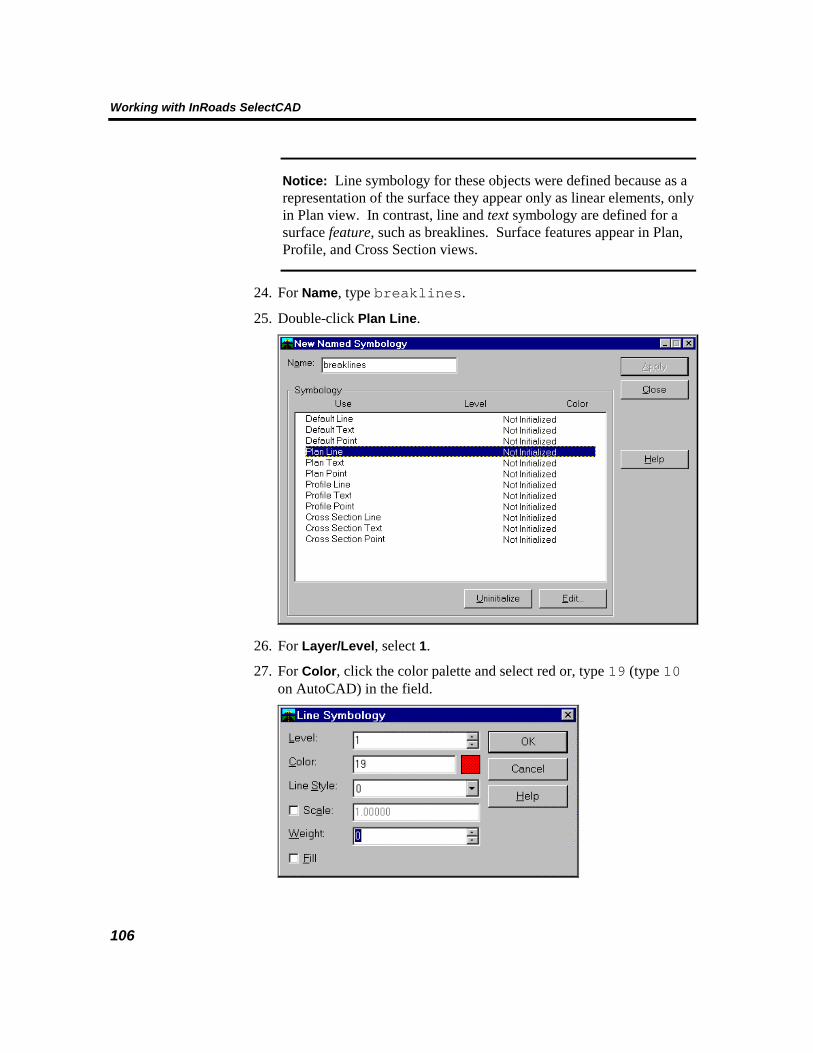
Working with InRoads SelectCAD
106
Notice: Line symbology for these objects were defined because as a representation of the surface they appear only as linear elements, only in Plan view. In contrast, line and text symbology are defined for a surface feature, such as breaklines. Surface features appear in Plan, Profile, and Cross Section views.
24. For Name, type breaklines.
25. Double-click Plan Line.
26. For Layer/Level, select 1.
27. For Color, click the color palette and select red or, type 19 (type 10on AutoCAD) in the field.

Learning InRoads SelectCAD
107
5
28. Accept all other default settings and click OK.
29. Double-click Plan Text.
30. For Layer/Level, select 1.
31. For Weight, select 1.
32. For Color, click the color palette and select blue or, type 17 (type 170 on AutoCAD) in the field.
33. Accept all other default settings and click OK.
34. Double-click Profile Line.
35. Repeat Steps 26 to 28.
36. Double-click Profile Text.
37. Repeat Steps 30 to 32.
38. Double-click Cross Section Line.
39. Repeat Steps 26 to 28.
40. Double-click Cross Section Text.

Working with InRoads SelectCAD
108
41. Repeat Steps 30 to 32.
42. Click Apply.
You have created symbology named breaklines. Breaklines now appear in the Symbology Manager list.
43. Click Close to dismiss the Symbology Manager dialog box.
Next, you will create a preference set for the surface original.
Creating a Surface Preference In this task, you will select symbology for the surface in the form of a preference set. A preference set is a group of settings that specify how objects that represent an individual surface are displayed. Surface preferences may include specialized symbology or other criteria that distinguishes one surface from another.
1. Click Tools > Preference Manager.
2. Click the Surface tab.
3. For Preference, type original and press Tab.
The preference set is named original to help remember the association with the surface named original.
4. In the Preferences section, double-click Perimeter.
The settings you previously defined for perimeter populates the dialog box.
The perimeter for surface original will display on layer/level 25 in Color 19.
5. Click Save.

Learning InRoads SelectCAD
109
5
6. In the Preferences section, double-click Triangles.
7. Double-click triangles (or click Edit).
8. Click Save.
9. In the Preferences section, double-click Contours.
10. Click Edit.
11. For Symbology Name, select contours.
Remember, you are modifying symbology here to create a preference set for the surface original.
12. Click OK.
13. Click Save.
The status for each surface object has changed from Not Initialized to Initialized. Initialized indicates that the entire preference set for the object is now active. The default system settings apply to objects not yet initialized.
10. Click Close.
You have successfully defined symbology and created a surface preference. Next, you will display the surface.
Displaying a Surface Perimeter

Working with InRoads SelectCAD
110
In this task, you display the perimeter of the surface original to view the extent of the DTM data contained in the surface.
1. Click Tools > Locks, and turn on Write lock.
2. Click Tools > Locks, and turn off Style lock.
3. Click Tools > Locks, and turn on Pencil mode.
4. From the CAD menu, turn on all levels/layers. On MicroStation, click Setting > Level > Display and ensure all levels are on. On AutoCAD, click Format > Layer and ensure all layers are on. Close all CAD dialog boxes.
5. Click Surface > View Surface > Perimeter.
6. Click Apply, and then click Close.
InRoads SelectCAD displays the perimeter of the surface original in
the drawing file.

Learning InRoads SelectCAD
111
5
7. If the perimeter is not visible on the screen, ensure that all display levels/layers are turned on.
Displaying Surface Contours In this section, you display the contours of the surface original.
1. Click Tools > Locks, and turn off Write lock.
2. Click Surface > View Surface > Contours.
3. Click the Main tab.
4. For the Surface, select original. For the Interval, type 1. For the Minors Per Major, type 4.
5. Under Symbology, turn off Labels.
Note: If you have previously placed a region or fence and the Region/Fence Mode is active, select Ignore.
Contours will be displayed every meter, with 4 minor contours between major contours.

Working with InRoads SelectCAD
112
In the next few steps, you save the settings you just made in the View Contours dialog box to the preference set for surface original. At any point while using InRoads SelectCAD, you can save the current settings of any command to a preference set. Different preference sets can be saved for later use.
You can save and load preference sets for InRoads SelectCAD commands or surfaces using the Preferences button located at the bottom or right side of most dialog boxes. Remember, when you add to a preference set the .ini file is modified. In this lesson, you modify the civilm_tut.ini file.
6. Click Preferences.
7. Make sure that original is highlighted. Click Save, and then click Close.
8. Click Apply on the View Contours dialog box.

Learning InRoads SelectCAD
113
5
InRoads SelectCAD computes the contour segments for each
elevation, connects them into polylines/linestrings, and displays the contours in the drawing file.
9. When the command is finished processing, click Close to dismiss the View Contours dialog box.
Using the Write Lock The Write lock command lets you display InRoads SelectCAD graphics in either temporary or permanent mode. When the Write lock is selected (on), graphics are written into the graphics file. These graphics can then be manipulated by using commands such as Delete, Move, Copy, and Change Color.
When the Write lock is not selected (off), graphics are displayed in temporary mode and will disappear as soon as the view is updated. This feature is convenient, for example, when you want to view the triangles or contours of a DTM, and then remove them from the screen.
10. Update (View/Redraw on AutoCAD) the view. Notice that the perimeter is redrawn on the screen. However, the contours are not redrawn because they were created with the Write lock turned off.
11. Click Tools > Locks > Toolbar to turn on the toolbar.
The Locks toolbar lets you control the status of several InRoads SelectCAD locks. Keep this toolbar docked on the SelectCAD Explorer or floating on the side of your screen as a convenient way to review and set your locks.

Working with InRoads SelectCAD
114
12. Turn on the Write lock by clicking the icon.
This is equivalent to using the Tools > Locks > Write command from the InRoads SelectCAD menu.
13. Click Surface > View Surface > Contours.
14. Click Apply to redisplay the contours.
15. Update the view.
The contours remain displayed because they were written to the graphics file.
16. Click Close to dismiss the View Contours dialog box.
17. Using your CAD software, delete the contours.

Learning InRoads SelectCAD
115
5
Using Write Lock with Pencil/Pen When Write lock is on, the Pencil/Pen command lets you temporarily (pencil) or permanently (ink) write to the graphics file. This concept is similar to drawing on paper. Using a pencil, you have the ability to quickly erase a drawing to remove it. In contrast, graphics drawn in ink are of a permanent form and must be deleted to be removed. The Delete Ink Lock command is used to removed graphics drawn in ink. These features are helpful when you want to display several iterations of a graphic until the desired graphic is displayed. Then, after comparing the objects, you can remove those not desired.
Ensure that Write lock is on, and the contours have been deleted.
1. Update the view. The perimeter is drawn on the screen.
2. Make sure that you are in Pencil mode.
This command is Either/Or meaning you are either in pencil mode or ink mode (unlike Write lock, which is either on or off).
3. Using your CAD software, move the perimeter.
4. Click Surface >View Surface >Perimeter.
5. Click Edit.
6. For Color, click the color palette and select a different color.
7. Click OK.
8. Click Apply, then click Close.

Working with InRoads SelectCAD
116
The first perimeter was erased and the second (current) perimeter was displayed. The perimeter is written to the design file because Write lock is on.
Note: If the graphic is not erased, click Tools > Options. Ensure the Omit Automatic Graphics Refresh option is turned off. When this option is on, graphic display is not refreshed: all graphics remain displayed.
9. Toggle to Pen mode.
10. Click Surface > View Surface > Perimeter.
11. Click Edit.
12. For Color, click on the color palette and select a different color.
13. Click OK.
14. Click Apply.
The previous graphic, written in pencil, is erased. The current perimeter is drawn in the graphics file in ink.
15. Using your CAD software, move the perimeter.
16. In the View Perimeter dialog box, click Apply again.
The second perimeter is displayed. The first graphic remains because it was written to the graphics file in ink.

Learning InRoads SelectCAD
117
5
17. Using your CAD software, move the second perimeter.
18. Toggle to Pencil Mode.
19. In the View Perimeter dialog box, click Edit.
20. On MicroStation, for Line Style, select 2. On AutoCAD, for Line Type, select a dashed type.
21. On MicroStation, for Weight, select 1.
22. Click OK.
23. Click Apply.
The third perimeter is drawn in pencil. It has a different line style.
24. Click Close to dismiss the View Perimeter dialog box.

Working with InRoads SelectCAD
118
Pen mode allows you to display several versions of a graphic; Pencil mode only allows you to display one.
25. Turn on Delete Ink Lock.
26. Click Surface >View Surface >Perimeter.
27. Click Edit.
28. For Color, click the color palette and select a different color.
29. On MicroStation, for Line Style, select 0. On AutoCAD, for Line Type, select Continuous.
30. On MicroStation, for Weight, select 1.
31. Click OK.
32. Click Apply.
The two perimeters written in ink are deleted because Delete Ink Lock is on. The perimeter written in pencil is removed because Pencil mode only retains the most recent graphic. The current (last) graphic is displayed.
33. Click Close to dismiss the View Perimeter dialog box.
34. Turn off Delete Ink lock.
Displaying Surface Triangles In the next task, you display the triangles that make up the faceted surface.

Learning InRoads SelectCAD
119
5
1. Turn off Write lock.
2. Click Surface > View Surface > Triangles.
3. For the Surface, select original.
Note: If you have previously placed a region or fence and the Region/Fence Mode is active, select Ignore.
4. Click Apply.
InRoads SelectCAD displays the triangles in the drawing file.
5. When processing is finished, click Close to dismiss the View
Triangles dialog box.
Looking at the displayed DTM, you should notice a feature running left-to-right across the entire surface. This is an existing road. In this

Working with InRoads SelectCAD
120
project, that road is part of the original ground. You will design a new road to run through this region. Later you can examine cross sections comparing the newly designed road against the existing ground.
6. For AutoCAD users only: if your triangles did not display in color, do the following:
• From the AutoCAD menu, click Tools > Preferences.
• Click the Display tab.
• Click Colors.
• Turn off the Monochrome Vectors toggle.
• Click OK on both the AutoCAD Window Colors and Preferences dialog boxes.
7. Update the view to remove the triangles.
Creating a Feature Style Now that you have displayed the objects that represent the surface, you can determine how and where features would appear in the surface. How and where a feature displays is determined by the feature style. In this task, you will define a feature style for surface breaklines. Breaklines commonly represent linear features, such as curblines and ditches in a roadway project.
1. Click Tools > Feature Style Manager.
2. Click New.
3. For Name, type breaklines.
4. For Description, type For surface original.
5. Under Symbology, for Name, select breaklines from the list.
The new feature style that you are creating is borrowing the symbology that you previously set for breaklines. These settings determine how the feature displays.
6. Under 3-D/Plan Display, click to turn on Line Segments.
These setting instruct InRoads SelectCAD to display breaklines in plan view. These setting determine where the feature displays.

Learning InRoads SelectCAD
121
5
7. Click Apply.
You have successfully created a feature style.
8. Click Close to dismiss the dialog box.
The new feature styles are listed in the Feature Style Manager dialog box.

Working with InRoads SelectCAD
122
9. Click Close to dismiss the dialog box.
Next, you will apply the feature style to all of the breaklines in the surface original.
10. Click Surface > Feature > Feature Properties.
11. For Surface, select original.
12. Highlight all breaklines in the Feature list.
Caution: Do not use the All button. You do not want to include the Random feature and the bottom of the list.
13. Under Style, for Primary select breaklines.

Learning InRoads SelectCAD
123
5
14. Click Apply.
The new feature style breaklines is applied to each breakline in the surface.
15. Click Close to dismiss the dialog box.
Creating a Feature Selection Filter Most roadway projects utilize many types of features. Once you have created and applied styles to feature-types in the surface, you can build a

Working with InRoads SelectCAD
124
selection set from which to choose features. In this task, you create a selection filter to only display breakline features.
1. Click Surface > Feature > Feature Selection Filter.
2. For Start With, select None.
3. Under Build Selection, for Attribute select Feature Type.
4. For Value, select Breakline.
5. For Mode, select Include.
6. Click the Add Rule button.
The breaklines appear in the Current Results list.
7. Click Save As.
8. For Name, type breaklines.
9. Click OK to dismiss the dialog box.
10. Click OK.

Learning InRoads SelectCAD
125
5
You have successfully created a feature selection filter.
Displaying Surface Features Once you have created a selection filter, you can quickly display surface features. In the final task for Lesson 2, you display all breaklines in the surface original.
1. Turn Write lock on.
2. In the Feature Filter list in the SelectCAD Explorer, select breaklines.
3. Turn on the Feature Filter Lock located next to the Feature Filter list field.
4. Click Surface > View Surface > Features.
5. For Surface, select original.
6. Scroll down the list. Only breaklines are listed and selected.

Working with InRoads SelectCAD
126
7. Click Apply.
8. Click Close to dismiss the dialog box.

Learning InRoads SelectCAD
127
5
9. Use the your CAD tools to delete the breaklines and perimeter.
10. Update the view.
11. From the CAD menu, save road.dgn or road.dwg.
12. From InRoads SelectCAD, click File > Save > Surface.
13. Click File > Exit and then exit your CAD software, or continue to the next lesson.

Working with InRoads SelectCAD
128
Lesson 3: Horizontal Alignment Design Now that you have modeled the existing surface by creating a DTM, the next phase of your road design is to define the planimetric position of the proposed road. To do this, you lay out a horizontal alignment. InRoads SelectCAD supports the definition of even the most complex alignments consisting of reverse curves, compound curves, and transition and compound spiral curves.
If you did not exit InRoads SelectCAD and the CAD software in the last lesson, skip to Setting Work Session Options. If you are just beginning the tutorial here, complete the following steps:
1. Extract roadlesson3.exe. For more information, see Before Starting Each Lesson at the beginning of this chapter.
2. Start InRoads SelectCAD, and open the road.dwg or road.dgn file. These files are located in the \Tutorial\InRoads directory where you installed InRoads SelectCAD.
3. Click File > Open.
4. For the Files of type, select Surfaces (*.dtm).
5. Set the directory to C:\Bentley\SelectCAD\Tutorial\InRoads.
6. Select original.dtm and click Open.
7. For the Files of type, select Preferences (*.ini).
8. Select civilm_tut.ini, and click Open.
9. For the Files of type, select Styles (*.ini).
10. Select wysiwyg.ini, and click Open.
11. Click Cancel to dismiss the dialog box.
Setting Work Session Options Before creating a geometry project, you must set the working units and decimal precision for coordinates, stationing, distances, angles and gradients.
1. Click Tools > Options.
2. Click the Precision tab. For Northing/Easting, select 0.123. For Elevation, select 0.123. For Angular, select 0.1. For Slope, select 0.1234. For Linear, select 0.123. For Station, select 0.123. Retain all other default precision settings. Click Apply.

Learning InRoads SelectCAD
129
5
15. Click the Units and Format tab. Under Units, for Linear, confirm
Metric. For Angular, confirm Degrees. Under Format, for Station, select s+sss.ss. For Angular, select ddd^mm’ss.s”. For Slope, select 50%. For Aspect, select ddd.ddd. Click Apply.

Working with InRoads SelectCAD
130
16. Click the General tab. For GUI Coordinate Sequence, select
Northing/Easting. Click Apply.
17. Click the Geometry tab. Under Curve Definition, For Horizontal, select Arc; for Vertical, select Parabolic. Turn on both toggles under Always Confirm. For Angular Mode, select Bearings. Click Apply.

Learning InRoads SelectCAD
131
5
18. Click Preferences.
19. Select default.
20. Click Save.

Working with InRoads SelectCAD
132
This updates the settings in the file. When you exit the product, the .ini file is saved so that next time you start InRoads SelectCAD the settings are the same.
21. Click Close to dismiss the Preferences dialog box.
You’ve modified the civilm_tut.ini file.
22. Click Close to dismiss the Options dialog box.
The Geometry Project InRoads SelectCAD stores coordinate geometry information in a geometry project (*.alg file). As you progress through the tutorial, you define a horizontal and a vertical alignment. This information is stored in the geometry project. You can save as many alignments and sets of points as you like in a geometry project.
This lesson describes several processes related to the geometry project: importing an existing alignment, defining horizontal alignments, and defining stationing and station equations. You create a geometry project; then, within that project you will create horizontal and vertical alignments. These alignments are the basis for defining the centerline for the proposed road.
Creating a Geometry Project 1. Click File > New.
2. Click the Geometry tab.
3. For the Type, select Geometry Project.
4. For the Name, type relocation. Press the TAB key.
5. For the Description, type road relocation project. Press the TAB key, and then click Apply.

Learning InRoads SelectCAD
133
5
6. For Type, select Horizontal Alignment.
7. For the Name, type baseline. Press the TAB key.
8. For the Description, type relocation baseline. Press the TAB key.
9. For Style, select default. Press the TAB key.
10. For Curve Definition, select Arc. Press the TAB key, then click Apply.

Working with InRoads SelectCAD
134
You have successfully defined the horizontal alignment name for the geometry.
11. For Type, select Vertical Alignment.
12. For the Name, type profile gradeline. Press the TAB key.
13. For the Description, type relocation baseline. Press the TAB key.
14. For Style, select default. Press the TAB key.
15. For Curve Definition, select Parabolic. Press the TAB key, then click Apply.

Learning InRoads SelectCAD
135
5
You have successfully defined a vertical alignment name. In the next task, you will create a horizontal alignment.
16. Click Close to dismiss the New dialog box.
InRoads SelectCAD provides several methods for creating horizontal alignments. One approach lets you add points of intersection (PIs) and curve sets. Another method allows you to design alignments using horizontal elements. Finally, for more complex road designs, you can use multiple element regression to create alignments. The first two methods are detailed in the following sections. You can choose to complete either one or both of the alignment workflows. For a detailed discussion of creating alignments using regression analysis, see the tutorial lessons for the Rail SelectCAD product.
To create a horizontal alignment using PIs, continue to the next section, otherwise, skip to Creating an Alignment by Horizontal Element Design.
Creating an Alignment by Horizontal Curve Set Now that you have created a geometry project, you can create the alignment for the new road. To begin, you will identify the initial tangents of the horizontal alignment by placing PIs. By connecting PI to PI, the centerline of the new road is created. You will finish up this task by creating curve sets to smooth out the alignment.

Working with InRoads SelectCAD
136
1. Click Surface > View Surface > Perimeter.
2. Click Apply, and then click Close.
3. Fit the perimeter in the view.
4. Click Geometry > Horizontal Curve Set > Add PI.
5. At the prompt: Identify alignment end, click in the CAD command window and type NE=3255.5,3124.8. Press the TAB key.
Note: If your command window does not appear, click Utitlites > Key-ins on MicroStation. For AutoCAD users, click in the command key-in field.
Move the mouse to see the beginning of the active horizontal alignment.
6. At the prompt: Identify Point/Reject, type NE=3400,3200 in the CAD command window. Press the TAB key.
Note: You can define a PI by keying in coordinates or by selecting the point graphically. When selecting the point graphically, the coordinates are displayed in the lower-left corner of the SelectCAD Explorer. For this lesson, you will key in each PI. When using the CAD key in window, you can press Enter or press the TAB key.
7. At the prompt: Identify Point/Reject, type NE=3540,3825 in the CAD command window. Press the TAB key.
8. At the prompt: Identify Point/Reject, type NE=4064.2,4470.2 in the CAD command window. Press the TAB key.
9. At the prompt: Identify Point/Reject, reject.
Note: Remember, on MicroStation left mouse click is accept; right mouse click is reject. On AutoCAD, right mouse click is accept and key in “R” is reject.
10. At the prompt: Identify alignment end, reject.

Learning InRoads SelectCAD
137
5
You have successfully added PIs to create tangents for the new alignment. Next, you define the curves.
11. Click Geometry > Horizontal Curve Set > Define Curve.
12. Under Horizontal PI, for Define By, select Direction and Distance From Previous PI.
13. For Direction Back, type N 27 30 E. Press the TAB key.
14. For Length Back, type 160. Press the TAB key.
15. Click the Design Calc. button.
16. Click the Road Design tab.
17. Under Curve Design, for Speed, select 80.
18. Under Select Table Entry, click on the first row (Maximum e of 4.00 and Radius of 280).

Working with InRoads SelectCAD
138
19. Click OK.
The Radius of 280 is displayed in the dialog box.
20. Under Horizontal Curve, for Leading Transition type 50. Press the TAB key. For Trailing Transition, type 50. Press the TAB key.

Learning InRoads SelectCAD
139
5
21. Click Apply.

Working with InRoads SelectCAD
140
InRoads SelectCAD computes a curve set at the second PI (between
the first and second tangent lines) and displays the message: Successful completion in the SelectCAD Explorer status field.
22. Click Next to move to the third PI.
23. Under Horizontal PI, for Define By, select Direction and Distance From Next PI.
24. For Direction Ahead, type N 50 50 E. Press the TAB key.
25. For Length Ahead, type 830. Press the TAB key
26. In the Horizontal Curve section, for Leading Transition type 35. Press the TAB key. For Radius, type 500. Press the TAB key. For Trailing Transition, type 35. Press the TAB key.

Learning InRoads SelectCAD
141
5
27. Click Apply.

Working with InRoads SelectCAD
142
You have successfully created a horizontal alignment.
28. Click Close to dismiss the Define Horizontal Curve Set dialog box.
Now is a good time to save your project.
29. Click File > Save As to save the geometry project.
30. Set the directory to C:\Bentley\SelectCAD\Tutorial\InRoads.
31. For the Save as type, select Geometry Projects (*.alg).
32. For the Active, select relocation.
33. For the File Name type relocation.alg, and click Save.
The geometry project called relocation, which contains the horizontal alignment data and the empty vertical alignment, is saved.
Note: As you progress through the workflow, you can periodically use the File > Save > Geometry Project command to save your project. Later, you can reload the geometry project using File > Open and set the File as type to Geometry Projects (*.alg).
34. Click Cancel to dismiss the dialog box. Now, skip to Defining the Beginning Station.

Learning InRoads SelectCAD
143
5
Creating an Alignment by Horizontal Element Design Now that you have created a geometry project, you can create the alignment for the new road.
1. Click Geometry > Horizontal Element > Add Fixed Line.
2. For Mode, select By Point, Direction and Distance.
3. In the Point section, click the Name check box to turn it on.
4. In Northing field, type 3255.5. Press the TAB key.
5. In Easting field, type 3124.8. Press the TAB key.
6. In the Parameters section, click the Direction check box to turn it on.
7. In the Direction field, type N 27 30 E. Press the TAB key.
8. In the Parameters section, click the Distance check box to turn it on.
9. In the Distance field, type 200. Press the TAB key.
10. Click Apply.
11. At the prompt: Accept/Reject, accept the solution.

Working with InRoads SelectCAD
144
12. Click Close to dismiss the dialog box.
13. Click Geometry > Horizontal Element > Add Floating Curve.
14. For Mode, select By Point and Radius.
15. Ensure that the Name check box is turn off.
16. Click Design Calc. button.
17. Click the Road Design tab.
18. Under Curve Design, for Speed, select 80.
19. In the Select Table Entry section, click on the first row (Maximum e of 4.00 and Radius of 280).

Learning InRoads SelectCAD
145
5
20. Click OK.
The Radius of 280 is displayed in the dialog box.
21. For Leading Transition, select Clothoid by Length.
22. In the Leading Transition field, type 50. Press the TAB key.
23. For Trailing Transition, select Clothoid by Length.
24. In the Trailing Transition field, type 50. Press the TAB key.

Working with InRoads SelectCAD
146
25. Click Apply.
26. At the prompt: Identify Element, place a datapoint adjacent to the linear element as shown:
You can dynamically place the floating curve.
27. At the prompt: Identify a Point, place a datapoint in the middle of the surface where the road might go.

Learning InRoads SelectCAD
147
5
Note: You can actually click anywhere in the surface because you are going to reject the solution. This step simply allows you to see that you can place a curve dynamically in graphics. In the next few steps you will place the curve with actual coordinates.
28. At the prompt: Accept/Reject, reject.
29. At the prompt: Identify element, reject.
30. In the Point section, click the Name check box to turn it on.
31. In the Northing field, type 3419.1965. Press the TAB key.
32. In the Easting field, type 3301.3151. Press the TAB key.
33. Click Apply.
34. At the prompt: Identify element, place a data point adjacent to the line.
35. At the prompt: Accept/Reject, accept the curve.

Working with InRoads SelectCAD
148
36. At the prompt: Identify element, reject.
37. Click Close to dismiss the dialog box.
38. Click Geometry > Horizontal Element > Add Floating Line.
39. For Mode, select By Point.
40. In the Point section, click the Name check box to turn it on.
41. In the Northing field, type 3510.1723. Press the TAB key.
42. In the Easting field, type 3695.3444. Press the TAB key.
43. Click Apply.
44. At the prompt: Identify element, place a data point near the end (but within) the circular arc as shown:

Learning InRoads SelectCAD
149
5
45. At the prompt: Accept/Reject, accept the line.
46. At the prompt: Identify element, reject.
47. Click Close to dismiss the dialog box.
48. Again, click Geometry > Horizontal Element > Add Fixed Line.

Working with InRoads SelectCAD
150
49. For Mode, select By Point, Direction and Distance.
50. In the Point section, click the Name check box to turn it on.
51. In Northing field, type 3558.9373. Press the TAB key.
52. In Easting field, type 3849.9504. Press the TAB key.
53. In the Parameters section, click the Direction check box to turn it on.
54. In the Direction field, type N 50 50 00.0 E. Press the TAB key.
55. In the Parameters section, click the Distance check box to turn it on.
56. In the Distance field, type 800. Press the TAB key.
57. Click Apply.
58. At the prompt: Accept/Reject, accept the line.

Learning InRoads SelectCAD
151
5
You have successfully created a horizontal alignment. Don’t be alarmed by the gap in the alignment, you will fix it later in the lesson.
59. Click Close to dismiss the dialog.
Now is a good time to save your project.
60. Click File > Save As to save the geometry project.
61. Set the directory to C:\Bentley\SelectCAD\Tutorial\InRoads.
62. For the Save as type, select Geometry Projects (*.alg).
63. For the Active, select relocation.
64. For the File Name type relocation.alg, and click Save.
The geometry project called relocation is saved.
Note: As you progress through the workflow, you can periodically use the File > Save > Geometry Project command to save your project. Later, you can reload the geometry project using File > Open and set the File as type to Geometry Projects (*.alg).
65. Click Cancel to dismiss the dialog box.
Defining the Beginning Station

Working with InRoads SelectCAD
152
Now that you have created an alignment, you can define the beginning station.
1. Click Geometry > Horizontal Curve Set > Stationing.
2. For Starting Station, type 10+000.000, and click Apply.
3. Click Close to dismiss the dialog box.
Next, you can review the alignment.
Reviewing the Horizontal Alignment Before fully displaying the alignment, now is a good time to review the alignment for any discontinuities. You can review the entire alignment or check the tangents, spirals, and stationing element by element.
1. Click Geometry > Review Horizontal.
2. In the Mode section, click Element.
This option displays individual elements within the alignment.
3. Click the Next button to move along the alignment.

Learning InRoads SelectCAD
153
5
Notice that as you move along the alignment, the element is highlighted in the graphics file.
4. Take a few minutes to review the alignment. You can use the Last, Previous and First buttons to navigate elements in the file.
5. If you created the alignment by curve sets, the review appears as shown below:
Creating an alignment by Horizontal Curve Set keeps elements collinear and connected. There are no warnings for this alignment.
6. If you created the alignment by horizontal design elements, the review appears as shown below:
Scroll down to the end of the file.

Working with InRoads SelectCAD
154
Notice the warning: Elements are not coincident. This means there are discontinuities within the alignment. Unlike creating an alignment with curve sets, creating an alignment by Horizontal Design Element does not force the alignment to be collinear and connected.
7. Click Print.
Note: If you do not have access to a printer, see Appendix B, Horizontal Alignment Review for a copy of these results.
8. Click Close to dismiss the dialog box.
If you just created the alignment by Horizontal Design Element, continue to the next task; otherwise, skip to Displaying an Alignment.
Resolving Discontinuties in a Horizontal Alignment Once you have reviewed an alignment and discovered discontinuities, you can connect elements to make them collinear.
1. Click Geometry > Horizontal Element > Add Free Curve.
2. For Leading Transition, select Clothoid by Length.
3. In the Leading Transition field, type 35. Press the TAB key.
4. For Radius, type –500. Press the TAB key.
5. For Trailing Transition, select Clothoid by Length.
6. In the Trailing Transition field, type 35. Press the TAB key.

Learning InRoads SelectCAD
155
5
7. Click Apply.
8. At the prompt: Identify first element, place a data point adjacent to the line to the left of the gap.
9. At the prompt: Identify second element, place a data point adjacent to the line to the right of the gap.
10. At the prompt: Accept/Reject, accept the curve.
11. At the prompt: Identify first element, right mouse click to return to the dialog box.
The elements are connected.
12. Click Close to dismiss the dialog box.

Working with InRoads SelectCAD
156
Displaying the Alignment Stationing With the beginning station defined, you are now able to display the stations along the alignment, and even define station equations, or points of station inequalities, along the alignment. In this task, you display the stationing along the centerline.
1. Click Tools > Locks and turn on Pencil mode.
Note: For AutoCAD, you must have Quick Text (Tools > Drawing Aids) turned off and the Write lock turned on to see the stationing text.
2. Click Geometry > View Geometry > Active Horizontal to see the elements and cardinal points of the alignment.
3. Click Geometry > View Geometry > Stationing.

Learning InRoads SelectCAD
157
5
4. Click the Regular Stations tab.
5. For Orientation in the MAJOR section, click Perpendicular.
6. In the Direction section, click Up Station.
7. For Placement, select Left.
8. For Justification, select Right Center.
9. For Precision, select 0.
10. For Format, select s+sss.sss.
11. For Offset, type 0.007. Press the TAB key.
12. For Ticks Left Offset, type –0.005. Press the TAB key.
13. For Ticks Right Offset, type 0.005. Press the TAB key.
14. For Ticks/Minors/Majors, type 4. Press the TAB key.

Working with InRoads SelectCAD
158
Note: The minor settings remain the default. In this lesson, you only display major tick marks.
15. Click the Cardinal Stations tab.
16. For Orientation, click Perpendicular.
17. For Direction, click Up Station.
18. For Placement, select In.
19. For Justification, select Right Center.
20. For Precision, select 0.123.
21. For Format, select s+sss.sss.
22. For Text, select Multiple Lines.
23. For Leader 1, type -0.120. Press the TAB key.
24. For Offset, type 0. Press the TAB key.
25. Click the PIs tab.
26. For Orientation, click Perpendicular.
27. For Direction, click Up Station.
28. For Placement, select Out.
29. For Justification, select Right Center.
30. For Precision, select 0.123.
31. For Format, select s+sss.sss.
32. For Text, select Multiple Lines.
33. For Leader 1, type –0.050. Press the TAB key.
34. For Offset, type 0. Press the TAB key.
35. Click the Main tab.
36. For Method, click Automatic.
37. For Interval, type 50. Press the TAB key.
38. Ensure that symbology for the following objects are turned on: Major Ticks, Major Stations, Cardinal Leader, Cardinal Station, PI Leader, PI Station. Turn off all other objects.
39. Click the Preferences button.

Learning InRoads SelectCAD
159
5
40. Select default and click Save to store the preferences in the civilm_tut.ini file.
41. Click Close to dismiss the Preferences dialog box.
42. Click Apply.
43. Use the Zoom command to see the stationing.
44. You can experiment with the different stationing displays by using the tabs or the Symbology Edit option located on the Main tab of the dialog box.

Working with InRoads SelectCAD
160
45. When you are finished, toggle to Pen mode. Click Apply one more time on the View Stationing dialog box, and then click Close to dismiss the dialog box.
46. Using your CAD software, save the road.dwg or road.dgn file.
47. From InRoads SelectCAD, click File > Save > Geometry Project.
48. Click File > Exit and then exit your CAD software, or continue to the next lesson.

Learning InRoads SelectCAD
161
5
Lesson 4: Profiles With the location of the horizontal alignment in place, the next step in designing a roadway is the definition of the design grade line or vertical alignment. Before you define the vertical alignment, you extract a profile of the original surface along the horizontal alignment. Then you use the surface profile as a reference for designing the vertical alignment.
When profiles are created, they are done so as a part of a set (even if there is only one profile within the set). Profiles are maintained as a part of a set so that they are easily identified when you want to update a profile or edit features within a specific profile. When a profile is created, it appears in the drawing file in a rectangular box, called the profile window. As you add segments to the vertical alignment, they appear in the profile window. This lesson covers profile generation. The next lesson covers vertical alignment layout within the profile and profile annotation.
If you just finished the lesson on horizontal alignments, skip to Generating a Profile Along an Alignment. If you are just beginning the tutorial here, complete the following steps:
1. Extract roadlesson4.exe. For more information, see Before Starting Each Lesson at the beginning of this chapter.
2. Start InRoads SelectCAD, and open the road.dwg or road.dgn file. These files are located in the \Tutorial\InRoads directory where you installed InRoads SelectCAD. For more information on starting the software, see Chapter 2, Starting InRoads SelectCAD.
3. Click File > Open.
4. Set the directory to C:\Bentley\SelectCAD\Tutorial\InRoads.
5. For the Files of type, select Preferences (*.ini).
6. Select civilm_tut.ini, and click Open.
7. For the Files of type, select Geometry Projects (*.alg).
8. Select relocation.alg, and click Open.
9. For the Files of type, select Surfaces (*.dtm).
10. Select original.dtm, and click Open.
11. Click Cancel to dismiss the dialog box.

Working with InRoads SelectCAD
162
Generating a Profile Along an Alignment To extract a profile, which represents the elevation of the existing surface original along the horizontal alignment centerline, complete the following steps.
1. Click Evaluation > Profile > Create Profile.
2. Click the Main tab.
3. For Create, select Window and Data.
4. For Set Name, a default name is provided: baseline. This profile set will contain only one profile and will be associated with the alignment baseline.
5. Under Source, for Alignment, select baseline.
6. Under Symbology, under Display, turn on the Surface, original.
This tells InRoads SelectCAD that the elevation data in surface original should be used for the profile.
7. Click the Features tab. Turn off all options.
8. Click the Controls tab.
9. Under Limits, ensure that both toggles are turned off.
10. Under Exaggeration, for Vertical, type 10.00. For Horizontal, type 1.0.

Learning InRoads SelectCAD
163
5
11. Click the Title tab.
12. For Title Text, type, Roadway Relocation Profile.
13. Under Placement, turn on Automatic.
14. Click Tools > Locks, and make sure that the Write lock is on.
15. Click Apply, and place a data point somewhere to the right of the surface original.
This location identifies the origin of the axes used in the profile generation (justified about the lower-left corner), and InRoads SelectCAD extracts and displays the profile at the specified point.
The graphics in the profile show the elevation of the existing ground along the path of the horizontal alignment.

Working with InRoads SelectCAD
164
Note: If the details of the profile, such as the title and text, do not appear, modify the symbology colors and redisplay the profile.
16. Use the CAD software Zoom commands to view the profile and legend.
17. You can turn off the Write lock and experiment with the parameters that control the operation of the Create Profile command by selecting the tabs on the Create Profile dialog box. When you are satisfied with the results, turn Write lock on and re-run the command. To save a setting, click Preferences on the dialog box. Select default, click Save then, Close.
18. When you are finished, click Close to dismiss the Create Profile dialog box.
19. Using your CAD software, save the road.dwg or road.dgn file.
20. Click File > Exit and then exit your CAD software, or continue to the next lesson.

Learning InRoads SelectCAD
165
5
Lesson 5: Vertical Alignments Now that you have extracted a profile of the existing terrain, you can define the longitudinal grade of the road using the existing ground as a reference. In this lesson, you create and define a vertical alignment. You define the vertical alignment within the bounds of a profile generated along a horizontal alignment. It is important to understand that a vertical alignment defines the elevations for a given horizontal alignment. In this way, a vertical alignment is related to a particular horizontal alignment.
If you just finished the lesson on profiles, skip to Creating a New Vertical Alignment. If you are just beginning the tutorial here, complete the following steps:
1. Extract roadlesson5.exe. For more information, see Before Starting Each Lesson at the beginning of this chapter.
2. Start InRoads SelectCAD, and open the road.dwg or road.dgn file. These files are located in the \Tutorial\InRoads directory where you installed InRoads SelectCAD. For more details on starting the software, see Chapter 2, Starting InRoads SelectCAD.
3. Click File > Open.
4. Set the directory to C:\Bentley\SelectCAD\Tutorial\InRoads.
5. For the Files of type, select Preferences (*.ini).
6. Select civilm_tut.ini, and click Open.
7. For the Files of type, select Geometry Projects (*.alg).
8. Select relocation.alg, and click Open.
9. For the Files of type, select Surfaces (*.dtm).
10. Select original.dtm, and click Open.
11. Click Cancel to dismiss the dialog box.
Creating a New Vertical Alignment InRoads SelectCAD provides three methods for creating a vertical alignment. One approach lets you add points of intersection (PIs) and curve sets. Another method defines the geometry by vertical element design. Finally, you can create a vertical alignment using regression analysis. The first two methods are detailed in this lesson. You can complete the instructions for one method or, you can practice creating alignments using both methods. For detailed instructions on creating a

Working with InRoads SelectCAD
166
vertical alignment using regression analysis, see the tutorial lessons for the Rail SelectCAD product.
To create a vertical alignment using curve sets, continue to the next section, otherwise, skip to Creating an Alignment by Vertical Element Design.
Creating an Alignment by Vertical Curve Set In this task, you create a new vertical alignment to define plan grade along the horizontal alignment centerline.
1. Click Geometry > Vertical Curve Set > Add PI.
Note: You can define a PI by keying in coordinates in the dialog box, keying in coordinates in the CAD command window, by selecting the point graphically. When selecting the point graphically, the coordinates are dynamically displayed in the lower-left corner of the SelectCAD Explorer. For this lesson, you will key in each PI in the CAD command window. You may need to move the collapsed dialog box to see the prompts in the lower-left corner of the Explorer.
2. Select Apply on the Add Vertical PI dialog box.
3. At the prompt: Identify alignment end, click in the CAD command window and type se=10000,289.65. Press the Enter key.
The beginning of the active vertical alignment is displayed in the profile.
4. At the prompt: Identify Point/Reject, type se=10250,296 in the CAD command window. Press the Enter key.
5. At the prompt: Identify Point/Reject, type se=10850,278 in the CAD command window. Press the Enter key.
6. At the prompt: Identify Point/Reject, type se=11250,295 in the CAD command window. Press the Enter key.
7. At the prompt: Identify Point/Reject, type se=11612.7999,296.30 in the CAD command window. Press the Enter key.
8. At the prompt: Identify Point/Reject, reject.
9. Reject again to redisplay the dialog box.
10. Close the Add Vertical PI dialog.

Learning InRoads SelectCAD
167
5
You have successfully added PIs to create tangents for the new vertical alignment. Next, you define the curves.
11. Click Geometry > Vertical Curve Set > Define Curve.
12. Under Vertical PI, for Define PVI By, select Station and Entrance Grade.
13. For Station, type 10+250. Press the TAB key.
14. For Entrance Grade, type 2.65%. Press the TAB key.
15. Under Vertical Curve, for Calculate By, select Length of Curve.
16. For Length, type 120. Press the TAB key.
The curve set will have a length of 120 meters.
17. Click Apply.
The first curve is placed:

Working with InRoads SelectCAD
168
The message: Successful completion is displayed in the SelectCAD Explorer.
18. Click Next to move up the alignment to compute the next curve set.
19. For Define PVI By, select Station and Elevation.
20. For Station, type 10+850. Press the TAB key.
21. For Elevation, type 278. Press the TAB key.
Next, you will use the design calculator to define the curve length.
22. Click the Design Calc. button.
23. For Method, select Lookup Speed.
24. Under Curve Design, for Range, turn on the Upper toggle.
25. For Speed, select 80.

Learning InRoads SelectCAD
169
5
26. Click OK.
Note: The calculated length of curve is 233.467. Since it is best to use an even number for curve length, type 234 in the Length of Curve field. Press the TAB key.

Working with InRoads SelectCAD
170
27. Click Apply.
28. Click Next to move up the alignment to complete the curve set.
29. For Define PVI By, select Station and Exit Grade.
30. For Station, type 11+250. Press the TAB key.
31. For Exit Grade, type 0.5%. Press the TAB key.
32. For Calculate By, select Length of Curve.
33. For Length, type 180. Press the TAB key.

Learning InRoads SelectCAD
171
5
34. Click Apply.
The final curve set is computed with a length of 180 meters.
The message: Successful completion is displayed in the SelectCAD Explorer.
35. Click Close to dismiss the dialog box.
Creating an Alignment by Vertical Element Design Once the horizontal alignment in a geometry project is in place, you can define elevations along the centerline of the new road.
1. Click Geometry > Vertical Element > Add Fixed Line.
2. For Mode, select By Point, Grade and Distance.
3. Click the Station check box to turn it on.
4. For Station, type 10+000. Press the TAB key.
5. For Elevation, type 289.65. Press the TAB key.
6. Click the Grade check box to turn it on.

Working with InRoads SelectCAD
172
7. For Grade, type 2.65%. Press the TAB key.
8. For Distance, type 250. Press the TAB key.
9. Click Apply.
10. At the prompt: Accept/Reject, accept the solution.
Next, you add the last tangent to the vertical alignment.
11. For Station, type 11+612.7999. Press the TAB key.
12. For Elevation, type 296.30. Press the TAB key.
13. For Grade, type 0.5%. Press the TAB key.
14. For Distance, type –400. Press the TAB key.

Learning InRoads SelectCAD
173
5
15. Click Apply.
16. At the prompt: Accept/Reject, accept the solution.
17. Click Close to dismiss the dialog box.
18. Click Geometry > Vertical Element > Add Floating Curve.
19. For Mode, select By Point and Parameter.
20. Click the Station check box to turn it on.
21. For Station, type 10+310. Press the TAB key.
22. For Elevation, type 294.4475. Press the TAB key.
23. In the Parameter section, select r = (g2-g1) / L and in the field, type -4.7485.

Working with InRoads SelectCAD
174
24. Click Apply.
25. At the prompt: Identify Element, place a data point near the end, but within the extents of the first tangent as shown:
26. At the prompt: Accept/Reject, accept the solution.
27. At the prompt: Identify element, reject/stop.
28. Click Close to dismiss the dialog box.
29. Click Geometry > Vertical Element > Add Floating Line.
30. For Mode, select By Point.

Learning InRoads SelectCAD
175
5
31. Click the Station check box to turn it on.
32. For Station, type 108+50. Press the TAB key.
33. For Elevation, type 278. Press the TAB key.
34. Click Apply.
35. At the prompt: Identify element, place a data point near the end (but within) the circular arc as shown:
36. At the prompt: Accept/Reject, accept the line.
37. At the prompt: Identify element, reject/stop.
38. Click Close to dismiss the dialog box.
39. Geometry > Vertical Element > Add Fixed Line.
40. For Mode, select By Point, Grade and Distance.
41. Click the Station check box to turn it on.

Working with InRoads SelectCAD
176
42. For Station, type 11+100. Press the TAB key.
43. For Elevation, type 288.3438. Press the TAB key.
44. Click the Grade check box to turn it on.
45. For Grade, type 4.1375%. Press the TAB key.
46. Click the Distance check box to turn it on.
47. For Distance, type 200. Press the TAB key.
48. Click Apply.
49. At the prompt: Accept/Reject, accept the line.
50. Click Close to dismiss the dialog box.
51. Click Geometry > Vertical Element > Add Free Curve.
52. For Length, type 320. Press the TAB key.

Learning InRoads SelectCAD
177
5
53. Click Apply.
54. At the prompt: Identify first element, place a data point near the second tangent:
55. At the prompt: Identify second element, place a data point near the third tangent:
56. At the prompt: Accept/Reject, accept the line.
57. At the prompt: Identify first element, reject/stop and return to the dialog box.
58. For Length, type 180. Press the TAB key.
59. Click Apply.
Next, place the final curve.
60. At the prompt: Identify first element, place a data point near the third tangent:

Working with InRoads SelectCAD
178
61. At the prompt: Identify second element, place a data point near the last tangent:
62. At the prompt: Accept/Reject, accept the curve.
63. At the prompt: Identify first element, reject/stop and return to the dialog box.
You have successfully created a vertical alignment.
66. Click Close to dismiss the dialog.
Save your project.
67. Click File > Save As to save the geometry project.
68. Set the directory to C:\Bentley\SelectCAD\Tutorial\InRoads.
69. For the Save as type, select Geometry Projects (*.alg).
70. For the Active, select relocation.
71. For the File Name type relocation.alg, and click Save.

Learning InRoads SelectCAD
179
5
Note: As you progress through the workflow, you can periodically use the File > Save > Geometry Project command to save your project. Later, you can reload the geometry project using File > Open and set the File as type to Geometry Projects (*.alg).
72. Click Cancel to dismiss the dialog box.
Reviewing a Vertical Alignment Before fully displaying the alignment, now is a good time to review it. You can review the entire alignment or check the tangents element by element.
1. Click Geometry > Review Vertical.
2. In the Mode section, click Element.
This option displays individual elements within the alignment.
3. Click the Next button to move along the alignment.
Notice that as you move along the alignment, the element is highlighted in the graphics file.
4. Take a few minutes to review the alignment. You can use the Last, Previous and First buttons to navigate elements in the file.
9. In the Mode section, click Alignment.
10. Click Print.
Note: If you do not have access to a printer, see Appendix C, Vertical Alignment Review for a copy of these results.

Working with InRoads SelectCAD
180
11. Click Close to dismiss the dialog box.
Profile Annotation Many profile sheets are annotated with, at a very minimum, the stationing and elevation of the existing ground and design grade. InRoads SelectCAD provides the ability to annotate many other alignment attributes, including superelevation rates and degree-of-curvature. By providing the ability to display these latter two parameters along the profile, InRoads SelectCAD gives you the means to properly blend horizontal and vertical alignment curves to meet well-established guidelines.
Displaying Vertical Alignment Annotation 1. Click Tools > Locks, and ensure that the Write lock is on.
2. Click Tools > Options > Factors to set Text Factor to 5.00. Click Apply; then Close.
3. Click Geometry > View Geometry > Vertical Annotation.

Learning InRoads SelectCAD
181
5
4. Click Apply.
5. At the prompt: Select profile window to be annotated, place a data point in the profile window.
6. Use your CAD Zoom commands to view the annotation.

Working with InRoads SelectCAD
182
7. Click Close to dismiss the dialog box.
8. Using your CAD software, save the road.dwg or road.dgn file.
9. Click File > Exit to exit InRoads SelectCAD, then exit your CAD software.

Learning InRoads SelectCAD
183
5
Lesson 6: Plan and Profile Generator You have successfully created a horizontal and vertical alignment for the proposed roadway, so now would be a good time to create initial plan and profile sheets for the project. Creating the sheets at this point in the process allows you see where the sheets will fall along the alignment.
In InRoads SelectCAD, the Plan and Profile Generator command is designed to assist you in assembling sheets along an alignment. The sheets may be plan sheets only, plan and profile sheets, or profile sheets only. Data for the plan views comes from plan view graphics already displayed in your CAD design/drawing file. Data for the profile views is created in your active CAD design/drawing file using this command. The Host file contains the title block and border information. The plan and profile views created are composed in a Host file as reference files or in viewports to your model file if you are using AutoCAD. If you are using AutoCAD, the sheets will always be composed in your current file. The plan view can be referenced from other files.
Once you have the parameters for all the tabs set, you can save the dialog settings to a preference file that can be loaded in a future design session so you do not have to re-enter all the parameters.
It is assumed that you know the basics of how to open and manipulate alignments and surfaces (See Lessons 1 through 3 for details). It is also assumed that you know the basics of how to set up the parameters for plotting a profile from within InRoads SelectCAD (See Lesson 4: Profiles for details).
Before You Start This Lesson For this lesson, the following preferences have been set for you and delivered with InRoads SelectCAD: 1) Plan and Profile Generator dialog box preferences, 2) profile preference border cells or blocks. Use the data delivered in the Tutorial directory for Lesson 6.
Note: If you did not exit InRoads SelectCAD and the CAD software in the previous lesson, stop here and exit.
In a real-world workflow, you should set and store in a preference file the parameters and symbology standards for the Create Profile command. The Plan and Profile Generator command requires that you specify which profile preference is used to control how the profiles are displayed in the design/drawing file.

Working with InRoads SelectCAD
184
To begin Lesson 6, complete the following steps:
1. Extract roadlesson6.exe. For more information, see Before Starting Each Lesson at the beginning of this chapter.
2. Start InRoads SelectCAD. On MicroStation from the \Tutorial\InRoads directory, open plprseed.dgn. Attach infra.cel to the design file. Then, open road.dgn and attach infra.cel to the design file.
Note: The cell infra.cel is located in the \Tutorial\InRoads directory. This cell must be attached to both design files.
On AutoCAD, open road.dwg located in the \Tutorial\InRoads directory where you installed InRoads SelectCAD. For more details on starting the software, see Chapter 2, Starting InRoads SelectCAD.
3. Click File > Open.
4. For the Files of type, select Preferences (*.ini).
5. Select civilpp_tut.ini, and click Open.
6. For the Files of type, select Styles (*.ini).
7. Select wisiwyg.ini, and click Open.
8. For the Files of type, select Geometry Projects (*.alg).
9. Select relocation.alg, and click Open.
10. For the Files of type, select Surfaces (*.dtm).
11. Select original.dtm, and click Open.
12. Click Cancel to dismiss the Open dialog box.
Defining and Creating the Views 1. Click Evaluation > Plan and Profile Generator.
2. AutoCAD User’s only, click Preferences. Select ACAD; then, click Load. Click Close to dismiss the preferences dialog box.
3. On the Main tab of the Plan and Profile Generator dialog box, confirm the following settings:
• Horizontal Alignment: baseline
• Method
Plan and Profile: on

Learning InRoads SelectCAD
185
5
Use Station Limits: on
• Sheets
Generate Sheets: on
VDF Information and Host Files: on
• Station Limits
Start Station Limits: 10 + 000.00
Stop Station Limits: 11 + 600.00
Length: 150.00
4. Click the Plan Controls tab, and confirm
5. the following settings:
Note: The plan controls determine how much of the plan will be shown to the left and right of the alignment. Left widths should be negative and right widths should be positive. If you want to show data on only one side of the alignment make both widths positive or both of them negative.

Working with InRoads SelectCAD
186
• Seed View Name: baseline
• Width Left: -35 (in model units, meters)
• Width Right: 35 (in model units, meters)
• Overlap: 10 (in model units, meters).
This distance is measured before and after the start and stop station, respectively, to extend the clipping boundary beyond the start and stop station of each view.
• Boundary Chords: 6.
This field lets you specify the number of chords on each side of the alignment view. Increasing the number of chords produces a smoother edge on the clipping boundary along curves. AutoCAD views will be rectangular view ports; the Boundary Chords field is not available for these CAD systems.
6. Click the Model Files button.
7. Set the directory to C:\Bentley\SelectCAD\Tutorial\InRoads
8. Select road.dwg or road.dgn. Click Open.

Learning InRoads SelectCAD
187
5
9. Click the Profile Controls tab, and confirm the following settings:
Note: The profile height is in elevation axis units.
Important Note: The profile views always use the current design file as the model file.
• Seed View Name: baseline
• Set Name: baseline
• Profile Preference: default
• Vertical Alignment: None
The surfaces that are highlighted and the vertical alignment that is chosen will be used to determine window clearances. The surfaces that are checked (X) will be drawn in the profile.
• Surface: original (highlighted and checked)
• Profile Elevation Shifts

Working with InRoads SelectCAD
188
Shift Where Needed: on
• Profile Height: 12
• Profiles per Column: 1
• Margins
Top: 3 (in model units, meters)
Bottom: 12 (in model units, meters)
Left: 16 (in model units, meters)
Right: 3 (in model units, meters)
Note: These margins are placed around the profile or window and extend the clipping boundary for the profile view. If you set these margin values to zero, the created view will not show any graphics (for example, axis annotation) outside the profile window (axes).
• Horizontal Spacing
Left to Left: on
Distance: 400
• Vertical Spacing
Bottom to Bottom: on
Distance: 100

Learning InRoads SelectCAD
189
5
10. Click the Sheet Layout tab. On MicroStation, confirm the following settings.
Note: AutoCAD user’s skip to Step 11.
• Sheet Number: 1
• Name: Plan and Profile 1
• Host File: sheets.dgn
• Seed Host File: plprseed.dgn
Note: If necessary, click Browse to locate these files in the \Tutorial\InRoads directory where you installed InRoads SelectCAD.
• Sheet Location
Layout along Alignment: on
This means the borders will be scaled up to fit along the horizontal alignment; the coordinates and bearing are preserved.

Working with InRoads SelectCAD
190
Round Rotation Angle: off
• Host File Content
All Sheets in One: on
• Clipping Boundary
• Unique Level for Each Sheet: on
11. AutoCAD user’s, click the Sheet Layout tab. Confirm the following settings.
• Sheet Number: 1
• Name: Plan and Profile 1
• Sheet Location
First Sheet Location
X = 0
Y = 0
Sheet per Column = 3
• Horizontal Spacing
Right to Left: On

Learning InRoads SelectCAD
191
5
Distance: 1
Top to Bottom: On
Distance: 1
12. Click the View Layout tab, and confirm the following settings:
• Location (Paper Units)
Plan X: 0.100 (0.100 meters from the Left edge of the sheet)
Plan Y: 0.620 (0.620 meters from the Bottom edge of the sheet)
Profile X: 0.100 (0.100 meters from the Left edge of the sheet)
Profile Y: 0.080 (0.080 meters from the Bottom edge of the sheet)
• Scale: 1 : 200 (1 meter on paper equals 200 meters in the model)
Both the plan and profile view will have the same scale. It is normally the same as the sheet scale.
13. Click the Border and Title tab, and confirm the following settings:

Working with InRoads SelectCAD
192
Note: Scale is not available in the AutoCAD because the border is placed in paper space at 1:1.
• Border Cell/Block: on
Name: A0
Level/Layer: 1
Unique Level for Each Cell: on
Level/Layer Step: 1
Scale: 200 (1 meter paper units is equivalent to 200 meter model units)
14. Click the Symbols and Details tab, and confirm the following settings:
• North Arrow

Learning InRoads SelectCAD
193
5
Attach: on
Cell/Block: NORTHM
Scale: 200 (On MicroStation) Scale: 1 (On AutoCAD)
• Location in Paper Units
X: 1.000 ( places the symbol origin 1 meter from the left edge of the sheet)
Y: 0.750 (places the symbol origin 0.750 meters from the bottom edge of the sheet).
15. Click the Match Lines tab.
16. For Station format, select s+sss.ss

Working with InRoads SelectCAD
194
Symbology settings for the sheets were previously prepared for this lesson.
• Under Object, click Plan Line. Notice to the right under Extend, the To Clipping Boundary is option is on. This indicates that the match line will extend up to the clipping boundary.
• Under Object, click Plan Start Station. Notice that you can add a prefix or suffix to the start station. A suffix has been provided for the lesson.
• Under Object, click Plan Stop Station. You can add a stop station prefix or suffix to the stop station.
• Under Object, click Plan Prev Sheet. You can add a prefix or suffix to the previous sheet.
• Under Object, click Plan Next Sheet. You can add a prefix or suffix to the next sheet.
All of these options are also available for each of the Profile symbology object settings. Take a moment to click through the Profile symbology settings.
17. Click the Sheet Index tab.

Learning InRoads SelectCAD
195
5
Note: For AutoCAD User’s, Object Snaps (OSNAP) must be toggled off before executing the plan and profile generator.
18. Click Apply.
19. At the prompt: Identify location, identify a location in the design/drawing for the profiles.
Horizontal alignment view definitions are created. These views are used to define the start and stop stations for the profile view definitions. Individual profiles are cut and placed in the current CAD file using the profile view definitions.
The first sheet is displayed. On MicroStation, you are now in sheets.dgn.
17. Click Show Sheet to display the highlighted sheet in the Sheet Index list.

Working with InRoads SelectCAD
196
18. The highlighted sheet is displayed in the view. Your are currently in the sheets.dgn design file.
Clipping Boundary
Match Line Match Line
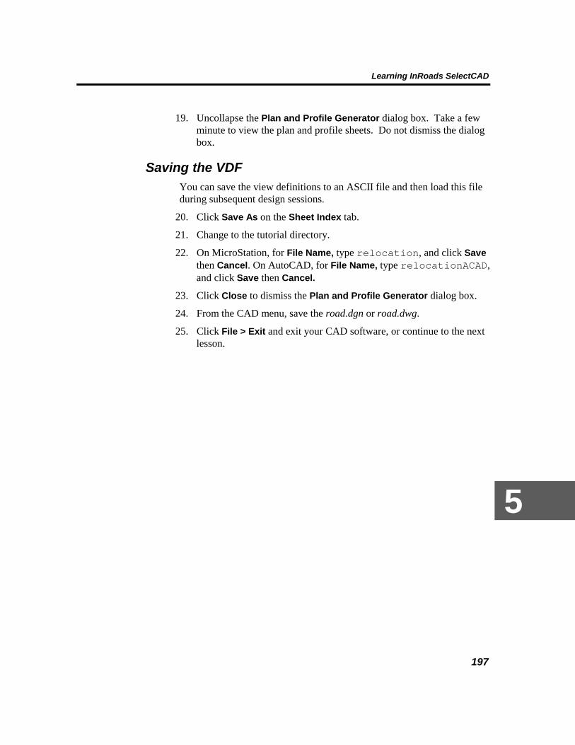
Learning InRoads SelectCAD
197
5
19. Uncollapse the Plan and Profile Generator dialog box. Take a few minute to view the plan and profile sheets. Do not dismiss the dialog box.
Saving the VDF You can save the view definitions to an ASCII file and then load this file during subsequent design sessions.
20. Click Save As on the Sheet Index tab.
21. Change to the tutorial directory.
22. On MicroStation, for File Name, type relocation, and click Save then Cancel. On AutoCAD, for File Name, type relocationACAD, and click Save then Cancel.
23. Click Close to dismiss the Plan and Profile Generator dialog box.
24. From the CAD menu, save the road.dgn or road.dwg.
25. Click File > Exit and exit your CAD software, or continue to the next lesson.

Working with InRoads SelectCAD
198
Lesson 7: Typical Sections A typical section consists of points and lines representing a cross section of the road. InRoads SelectCAD uses typical sections to define the geometry of the roadway as a cross section. The surface of the road is defined by placing typical sections at intervals along the alignment using the elevations defined in the vertical alignment.
A typical section is comprised of four types of definitions: Templates, Cut/Fill Tables, Material Tables, and Decision Tables. You learn more about these later in the lesson.
The main portion of the typical section usually defines the travel lanes and the shoulder. This section is called a backbone. The left and right backbone zones of your roadway never intercept an existing surface. It is in these two zones that superelevation of the roadway occurs. Everything outside the backbone is called the exterior portion of the typical section. Generally, the slopes and widths of the backbone do not vary from what is defined, but the widths of the exterior portions will vary depending on the amount of cut or fill needed to intersect existing ground.
InRoads SelectCAD defines the surface of a road using typical cross sections. A typical section defines the cross section of a road at a single station on the alignment. However, typical sections define an entire roadway surface when they are applied successively along an alignment.
In this lesson, you create a typical section library and create and define a template for a four-lane road. You then save the typical section library to disk. Typical section libraries allow you to save typical sections (such as templates) so that they can be accessed by different users or on different roadway design projects.
If you just finished the lesson on creating plan and profile sheets, skip to Creating a Typical Section Library. If you are just beginning the tutorial here, complete the following steps:
1. Extract roadlesson7.exe. For more information, see Before Starting Each Lesson at the beginning of this chapter.
2. Start InRoads SelectCAD, and open the road.dwg or road.dgn file. These files are located in the \Tutorial\InRoads directory where you installed InRoads SelectCAD. For more information on starting the software, see Chatper 2, Starting InRoads SelectCAD.
3. Click File > Open.
4. Set the directory to C:\Bentley\SelectCAD\Tutorial\InRoads.

Learning InRoads SelectCAD
199
5
5. For the Files of type, select Preferences (*.ini).
6. Select civilpp_tut.ini, and click Open.
7. For the Files of type, select Styles (*.ini).
8. Select wysiwyg.ini, and click Open.
9. Click Cancel to dismiss the dialog box.
Creating a Typical Section Library 1. Click File > New.
2. Click the Typical Section Library tab.
3. For the Name, type relocation. Press the TAB key.
4. For the Description, type For use on relocationprojects. Press the TAB key.
Note: The files used in this tutorial are named the same. It is good practice to name all your files the same for a project. It helps with backups and archiving the project information.
5. Click Apply.

Working with InRoads SelectCAD
200
InRoads SelectCAD creates a new typical section library in memory. You must save the library to a file for later use.
6. Click Close to dismiss the dialog box.
7. Click File > Save As.
8. Set the directory to C:\Bentley\SelectCAD\Tutorial\InRoads.
9. For the Save as type, select Typical Section Libraries (*.tml).
10. For the File Name, type relocation.tml.
11. Click Save.
InRoads SelectCAD creates the file relocation.tml and saves the typical section library in it.
12. Click Cancel to dismiss the dialog box.
Throughout the remainder of this section, as you are defining typical sections, you should periodically use the File > Save > Typical Section Library command to save the defined typical sections to the typical section library file.
Defining Transition Controls Before you define a typical section, you create transition controls (TCs). TC entries are codes you assign to each point in a template to control how these points are to be connected longitudinally, and to which features they are assigned. The entries determine the name and style of the features that are placed in the DTM when you run the roadway modeler.
During the modeling process, transition controls allow you to override the default settings when, during a transition between two templates, there are different numbers of segments (such as going from a two-lane highway to a four-lane highway). In this situation, by default the roadway modeling process attaches centerline points, left hinge points, and right hinge points together. Then, the modeler works outward from the centerline, attaching successive template segment points together. To override this modeling action, you can assign common transition-control names to points on both templates. This forces the points to be connected with one another at successive applications of the template.
Creating Transition Control Entries In InRoads SelectCAD, transition control entries (codes) are used to create features in a surface by running by Roadway Modeler. Each feature has a feature style. In this task, you first define feature styles. Later you will associate the feature styles with the following roadway transition control

Learning InRoads SelectCAD
201
5
codes: edge of pavement, shoulder, cut, fill, ditch foreslope, backslope and bottom. . If you are beginning the tutorial here, it may be helpful to review Creating a Feature Style in Lesson 1.
1. Click Tools > Feature Style Manager.
2. Click the New button.
3. For Name, type eop.
4. Click Description, type edge of pavement.
5. Under Symbology, click the New button.
6. For Name, type eop.
7. Double-click on Plan Line.
8. For Color, click on the color palette and select yellow.
9. For Line Style, select 0.
10. Keep all other default settings.
11. Click OK to dismiss the Symbology dialog box.
12. Double-click on Profile Line.

Working with InRoads SelectCAD
202
13. Repeat Steps 8 to 11.
14. Double-click Cross Section Line.
15. Repeat Steps 8 to 11.
16. Click Apply then Close to dismiss the New Named Symbology dialog box.
17. The named symbology for the edge of pavement feature is created.

Learning InRoads SelectCAD
203
5
Now, define how and where the feature will display.
18. Under 3-D Plan/Display, click on Line Segments to turn it on.
19. Under Cross Section Display, turn on Points and Annotation.
20. Under Profile Display, leave all options turned off.

Working with InRoads SelectCAD
204
21. Click Apply. Do not dismiss the dialog box.
The feature and description are displayed in the Feature Style Manager list.
You have successfully created a feature style for edge of pavement.

Learning InRoads SelectCAD
205
5
Repeat Steps 3-16 for the following features. For the Description, type for relocation.
Feature Color
shoulder gray
cut green
fill red
ditch foreslope gray
ditch backslope gray
ditch bottom Gray
When you are finished, the Feature Style Manager list should appear as shown:
22. Click Close to dismiss the New Feature Style dialog box.
23. Click Close to dismiss Feature Style Manager.
The feature style settings are saved to the .ini file. Next, you will associate the feature styles with transition control entries. These entries are used later in the lesson to create the roadway template.
24. Click Modeler > Define Typical Sections.
25. Click the Transition Control tab.

Working with InRoads SelectCAD
206
The feature style settings stored in the .ini file are automatically displayed.
26. Click the New button.
27. For Name, type outside lane. Press the TAB key.
Note: Remember to press the TAB key to move through the dialog box.
28. For Description, type Edge of pavement.
29. For Feature Style, select eop from the droplist.

Learning InRoads SelectCAD
207
5
The symbology previously defined for the feature edge of pavement is displayed.
30. Click Apply. Do not dismiss the dialog box.
The entry is displayed in the transition control list.
Create the remaining entries.
31. For Name, type inside lane.
32. For Description, type Edge of pavement.
33. For Feature Style, select eop from the droplist.

Working with InRoads SelectCAD
208
34. Click Apply.
35. For Name, type ditch bottom inside.
36. For Description, type Ditch bottom.
37. For Feature Style, select ditch bottom from the droplist.
38. Click Apply.
39. For Name, type ditch bottom outside.
40. For Description, type Ditch bottom.
41. For Feature Style, select ditch bottom from the droplist.
42. Click Apply.
The transition control list should appear as shown:
You have successfully created transition control entries.
43. Click Close to dismiss the dialog box.
Now is a good time to save the typical section library.
44. Click File > Save > Typical Section Libraries.
Defining Typical Sections Now that you have created a typical section library with transition control entries, you can create a typical section. The typical section you define in
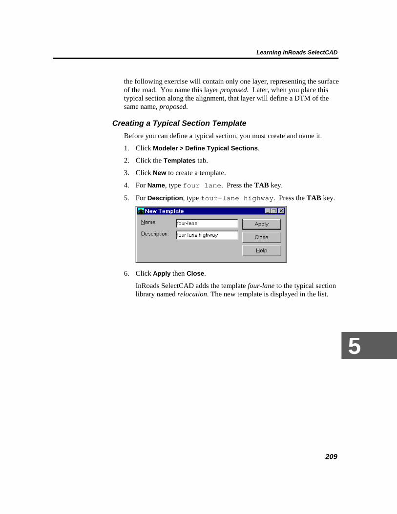
Learning InRoads SelectCAD
209
5
the following exercise will contain only one layer, representing the surface of the road. You name this layer proposed. Later, when you place this typical section along the alignment, that layer will define a DTM of the same name, proposed.
Creating a Typical Section Template Before you can define a typical section, you must create and name it.
1. Click Modeler > Define Typical Sections.
2. Click the Templates tab.
3. Click New to create a template.
4. For Name, type four lane. Press the TAB key.
5. For Description, type four-lane highway. Press the TAB key.
6. Click Apply then Close.
InRoads SelectCAD adds the template four-lane to the typical section library named relocation. The new template is displayed in the list.

Working with InRoads SelectCAD
210
7. Double-click on the template (or select it and click the Edit button.).
8. Click the Layer tab.
9. For Name, type proposed. Press the TAB key.
This template layer will be used as the surface name later in the tutorial when the roadway modeler places templates at intervals along the horizontal alignment.
10. For Description, type surface course and side slopes. Press the TAB key.
11. Keep all of the other default settings, including Horizontal and Vertical Offsets at 0.00.
12. Click New.

Learning InRoads SelectCAD
211
5
13. Click Close to dismiss the dialog box.
You have successfully created a template layer.
Adding Segments to a Template Layer Now that a template layer has been created and stored in the typical section, you can add segments.
1. Click the Segment tab.
Here, you define the slope, width and other parameters for the layer segment. These settings determine how features are added to the proposed surface. Begin with the right side of the roadway.
2. For Zone, select Right backbone.
3. For Edit Mode, select Add After.
This instructs the software to append segments to one another as they are added.
4. For Fixity, select Fixed.
5. In the TC list, scroll down and select (highlight) inside lane.
6. In the Input section, for Slope type –0.020. Press the TAB key.
7. For Width, type 3.650. Press the TAB key.

Working with InRoads SelectCAD
212
8. Click New.
InRoads SelectCAD adds a segment that is 3.65 meters wide and has a slope of –0.02%. This segment, which starts at the centerline, is added to the layer proposed.
9. Scroll down the TC list and select outside lane.
10. Click New.
The segment is automatically added.
11. From the list, select Shoulder. For slope, type –0.040. Press the TAB key. For Width, type 1.500. Press the TAB key.
12. Click New.
This 1.5 meter segment is the shoulder of the road. You have completed all segments for the right lane. Next, create three segments for the left lane.
13. For Zone, select Left Backbone.
14. From the list, select inside lane. For Slope, type –0.020. Press the TAB key. For Width, type 3.650. Press the TAB key.
15. Click New.

Learning InRoads SelectCAD
213
5
16. From the list, select outside lane. For Slope, type –0.020. Press the TAB key. For Width, type 3.650. Press the TAB key.
17. Click New.
18. From the list, select Shoulder. For Slope, type –0.040. Press the TAB key. For Width, type 1.500. Press the TAB key.
19. Click New.
20. Click Close to dismiss the Edit Template dialog box.

Working with InRoads SelectCAD
214
The left and right backbone zones are displayed.
21. Click Close to dismiss the dialog box.
22. Save the typical section library named relocation using the File > Save Typical Section Library command.
You just defined a template, saved it to a typical section library, and saved the typical section library to a file on the hard disk. You will use the template later to model the roadway using the Roadway Modeler command.
23. Click File > Exit and then exit your CAD software, or continue to the next lesson.

Learning InRoads SelectCAD
215
5
Lesson 8: Decision Tables Once the roadway template has been created, you are ready to define the side slopes. In InRoads SelectCAD, the most powerful tool for defining your roadway side slopes is a decision table. Decision Tables allow you to check multiple design scenarios at each location at which a typical section is placed along your roadway.
A decision table is a list of line segments that are projected transverse to your alignment, starting from the edge of the typical section, and seeking an intersection with a target-usually the existing ground. The segments are combined in sequences which are considered to be successful if they hit the target. Successful sequences are retained and stored in your design model.
Multiple targets can be incorporated in a single table, allowing you to design retaining walls, ditches, and so on. See the InRoads SelectCAD Online Reference topics for a more in-depth overview of how decision table work.
In this lesson, you create a decision table to define the side slopes for the new roadway.
If you just finished the lesson on typical sections, skip to Creating a Decision Table. If you are just beginning the tutorial here, complete the following steps:
1. Extract roadlesson8.exe. For more information, see Before Starting Each Lesson at the beginning of this chapter.
2. Start InRoads SelectCAD, and open the road.dwg or road.dgn file. These files are located in the \Tutorial\InRoads directory where you installed InRoads SelectCAD. For more details on starting the software, see Chapter 2, Starting InRoads SelectCAD
3. Click File > Open.
4. Set the directory to C:\Bentley\SelectCAD\Tutorial\InRoads.
5. For the Files of type, select Preferences (*.ini).
6. Select civilpp_tut.ini, and click Open.
7. For the Files of type, select Styles (*.ini).
8. Select wysiwyg.ini, and click Open.
9. For the Files of type, select Surfaces (*.dtm).
10. Select original.dtm, and click Open.

Working with InRoads SelectCAD
216
11. For the Files of type, select Typical Sections Libraries (*.tml).
12. Select relocation.tml, and click Open.
13. Click Cancel to dismiss the dialog box.
Creating a Decision Table Before you can define the content of a decision table, you must create it and name it.
1. Click Modeler > Define Typical Sections.
2. Click the Decision Tables tab.
3. Click New.
4. For the Name, type End of roadway. Press the TAB key.
5. For the Description, type Treatment for end of proposedroadway. Press the TAB key.
6. Click Apply.
7. Close Close to dismiss the New Decision Table dialog box.
You have successfully created a decision table in memory. Next, define the decision table segments.

Learning InRoads SelectCAD
217
5
Creating Decision Table Segments 8. Double-click on End of roadway in the list (or select it and click the
Edit button.)
The Edit Decision Table dialog box is displayed. This dialog box allows you to set the slope and width of the segments. First, you will define a ditch to ensure minimum drainage.
9. Click Add After.
10. Click on the New Target and New Group toggles to turn them on.
These toggles instruct the software to create a new target block and new target group after successfully hitting a target and placing the segment.
11. For Target Type, select Surface.
12. For Surface, select original.
13. Under Segment, for Start TC Name, select Hinge.
14. For End TC Name, select Ditch Foreslope.
15. For Slope, type -1:4. Press the TAB key.
16. For Width, type 4.0. Press the TAB key.
17. Click on the Seek Intersection toggle to turn it off.

Working with InRoads SelectCAD
218
This toggle instructs the software to not seek an intersection with the surface.
18. Click on the Construct Point toggle to turn it on.
This toggle instructs the software to place the point (of intersection) in the model if the target block is successful.
19. Click Apply. Do not close the dialog box; you will create additional
segments.
The new record is stored and the segment is saved to the decision table.
If the segment cannot hit the specified target, the table proceeds to the next group for Fill condition.
20. Turn off New Target and New Group.
21. Under Segment, for Start TC Name, select Ditch Foreslope.
22. For End TC Name, select Ditch Bottom.
23. For Slope, type 0. Press the TAB key.
24. For Width, type 1.0. Press the TAB key

Learning InRoads SelectCAD
219
5
25. Click on the Seek Intersection toggle to turn it on.
26. Ensure that Construct Point is on.
27. Click Apply.
If the target is successfully hit, the table stops. This segment allows drainage from under the roadway.
28. Ensure that New Target and New Group are turned off.
29. Under Segment, for Start TC Name, select Ditch Bottom.
30. For End TC Name, select Cut.
31. For Slope, type 1:3. Press the TAB key.
32. For Width, type 10.00. Press the TAB key.
33. Turn on Seek Intersection and Construct Point.

Working with InRoads SelectCAD
220
34. Click Apply.
If the target is hit, the table stops; otherwise, it proceeds to the next record checking for a steeper slope.
35. Ensure that New Target and New Group are turned off.
36. Under Segment, for Start TC Name, select Ditch bottom.
37. For End TC Name, select Cut.
38. For Slope, type 1:2. Press the TAB key.
39. For Width, type 50.0. Press the TAB key.
40. Ensure that Seek Intersection and Construct Point are on.

Learning InRoads SelectCAD
221
5
41. Click Apply.
If the target is successful, the table stops; otherwise, it is assumed that the roadway is in Fill condition. Next, define the segments for Fill .
42. Turn New Target and New Group on.
Surface and original are already selected as target and surface, respectively.
43. Under Segment, for Start TC Name, select Hinge.
44. For End TC Name, select Fill.
45. For Slope, type -1:4. Press the TAB key.
46. For Width, type 20.0. Press the TAB key.
47. Ensure that Seek Intersection and Construct Point are on.

Working with InRoads SelectCAD
222
48. Click Apply.
If the target is not successful, the table proceeds to the next record checking for a steeper slope.
49. Ensure that New Target and New Group are turned off.
50. Under Segment, for Start TC Name, select Hinge.
51. For End TC Name, select Fill.
52. For Slope, type -1:3. Press the TAB key.
53. For Width, type 20.0. Press the TAB key.
54. Ensure that Seek Intersection and Construct Point are on.

Learning InRoads SelectCAD
223
5
55. Click Apply.
If this segment fails, the roadway is in a 50% Fill. In this case, a guardrail is required, so the next segment will first extend the Shoulder.
56. Ensure that New Target and New Group are turned off.
57. Under Segment, for Start TC Name, select Hinge.
58. For End TC Name, select Shoulder.
59. For Slope, type –4.0%. Press the TAB key.
60. For Width, type .75. Press the TAB key.
61. Turn Seek Intersection off.
62. Ensure Construct Point is on.

Working with InRoads SelectCAD
224
63. Click Apply.
64. Ensure that New Target and New Group are turned off.
65. Under Segment, for Start TC Name, select Shoulder.
66. For End TC Name, select Fill.
67. For Slope, type -1:2. Press the TAB key.
68. For Width, type 10.00. Press the TAB key.
69. Turn Seek Intersection and Construct Point on.

Learning InRoads SelectCAD
225
5
70. Click Apply.
71. Turn on New Target
72. Turn off New Group.
73. For Start TC Name, select Fill.
74. For End TC Name, select Ditch Foreslope.
75. For Slope, type -1:3. Press the TAB key.
76. For Width, type 3.0. Press the TAB key.
77. Turn Seek Intersection off.
78. Ensure Construct Point is on.

Working with InRoads SelectCAD
226
79. Click Apply.
80. Ensure that both New Target and New Group are turned off.
81. For Start TC Name, select Ditch Foreslope.
82. For End TC Name, select Cut.
83. For Slope, type 1:3. Press the TAB key.
84. For Width, type 10.00. Press the TAB key.
85. Ensure that both Seek Intersection and Construct Point are on.

Learning InRoads SelectCAD
227
5
86. Click Apply.
The ditch defined here will carry water away from the base of a high Fill. The decision table can add this record to the end of a successful target and again intersect the same surface or other target type.
You have successfully created a decision table.
87. Click Close to dismiss the Decision Table Record dialog box.

Working with InRoads SelectCAD
228
88. Click Close to dismiss the Edit Decision Table dialog box.
89. Click the Display button to view a graphic representation of the decision table records.
90. At the prompt: Identify Point/Reject, datapoint in a clear area of the graphics window.
91. Use your CAD Zoom command to view the graphics. These graphics show the side slope treatment you just defined for the proposed roadway.
92. Click Close to dismiss the Define Typical Sections dialog box.

Learning InRoads SelectCAD
229
5
93. Use the CAD Delete command to remove the decision table graphics.
94. Click File > Save > Typical Section Library.
95. Click File > Exit and then exit your CAD software, or continue to the next lesson.

Working with InRoads SelectCAD
230
Lesson 9: Roadway Libraries So far, you have defined an original surface, horizontal and vertical alignments, a typical section, and a decision table. The final step before you can generate a roadway model is to create a roadway definition, which describes which typical sections to use along the alignment, how often to place them, and which method to use to control side slopes.
In this lesson, you create a roadway definition, which controls the roadway modeling process. The roadway definition will specify the template four lane every 10 meters along the centerline alignment baseline, from station 10+000 to station 10+300, using the vertical alignment profile gradeline. The definition will also identify the decision table, End of roadway, which you created earlier, as the means of determining side slopes.
After you complete this roadway definition, you save it in a roadway library. The benefit of having a roadway library is that you can create and store various roadway definitions for combinations of existing alignments, templates, and slide-slope controls.
If you just finished the lesson on decision tables, skip to Creating a New Roadway Library. If you are just beginning the tutorial here, complete the following steps:
1. Extract roadlesson9.exe. For more information, see Before Starting Each Lesson at the beginning of this chapter.
2. Start InRoads SelectCAD, and open the road.dwg or road.dgn file. These files are located in the \Tutorial\InRoads directory where you installed InRoads SelectCAD. For more details on starting the software, see Chapter 2, Starting InRoads SelectCAD.
3. Click File > Open.
4. Set the directory to C:\Bentley\SelectCAD\Tutorial\InRoads.
5. For the Files of type, select Preferences (*.ini).
6. Select civilpp_tut.ini, and click Open.
7. For the Files of type, select Styles (*.ini).
8. Select wysiwyg.ini, and click Open.
9. For the Files of type, select Typical Section Libraries (*.tml).
10. Select relocation.tml, and click Open.
11. Click Cancel to dismiss the dialog box.

Learning InRoads SelectCAD
231
5
Creating a New Roadway Library In this lesson, you create a new roadway library and save the library to a roadway library file.
1. Click File > New.
2. Click the Roadway Library tab.
3. For the Name, type relocation. Press the TAB key.
4. For the Description, type tutorial roadway library. Press the TAB key, and click Apply.
5. Click Close to dismiss the dialog box.
InRoads SelectCAD generates a new roadway library named relocation. The roadway library currently exists only in temporary memory. You must now save the file to your hard disk.
6. Click File > Save As command.
7. For the Save File as type, select Roadway Libraries (*.rwl).
8. For the File Name, type relocation.rwl. Click Save.

Working with InRoads SelectCAD
232
InRoads SelectCAD creates a file named relocation and saves the new roadway library to that file.
9. Click Cancel to dismiss the dialog box.
Creating a Roadway Definition Once the roadway library has been created, you can create a roadway definition. A roadway definition specifies which typical section to place, how often to place it, and how to determine the side slopes.
The basic content of a roadway definition is a list of stations and templates. The stations and templates define which template to use along which parts of the alignment. Each template is used from its corresponding station until the station of the next entry in the list.
1. Click Modeler > Define Roadway.
2. Click New to add a new roadway definition.
3. For the Name of the roadway definition, type proposal 1. Press the TAB key.
4. For the Description, type proposal using four lane. Press the TAB key, and click Apply.
5. Click Close to dismiss the New Roadway dialog box.
InRoads SelectCAD creates a new roadway definition named proposal 1.

Learning InRoads SelectCAD
233
5
6. Double-click on the roadway definition proposal 1 (or select it and click the Edit button.
The Edit Roadway dialog box will list all station and template entries for the roadway named proposal 1. Because this roadway definition has just been created, it does not yet contain any station and template entries.
7. Click New on the Edit Roadway dialog box.
The Roadway Entry dialog box contains all parameters that affect how a template is placed along the alignment.
8. For the Station, type 0+000.000.
This defines where to start placing the templates along the alignment.
9. For the Mode, select Both.
By doing this, you force InRoads SelectCAD to use the same template on the left and right sides of the horizontal alignment centerline.
10. For the Interval, type 10.000.
This tells InRoads SelectCAD to place a template every 10 meters along the alignment.
11. Click on the Use Transition Template toggle to turn it on.
In this lesson, there is only one entry in the roadway definition so this toggle won’t have an affect in this particular workflow. However, if

Working with InRoads SelectCAD
234
additional roadway entries are added to the list, you would want to linearly transition from one template to the next without an abrupt change in the roadway where the modeler changes templates.
12. Under Alignment Side Options, for Templates, select four lane.
The template name four lane appears in the Template field. InRoads SelectCAD will use the template named four lane as the basis for modeling the roadway corridor.
13. For the Catch Point, select Decision Table.
14. For Name, select End of roadway. You created this table in the previous lesson.
InRoads SelectCAD will retrieve the appropriate slope information from this decision table as it computes side slopes for the roadway model.
15. Other parameters are available on this dialog box, but for this example just click Apply, and then click Close
A single station and template entry appears in the Edit Roadway dialog box. The template four lane is used beginning at station 0+000 for the entire alignment. At this point, you could add additional station and template entries, and InRoads SelectCAD would automatically transition between the templates. However, you use only one template in this lesson.

Learning InRoads SelectCAD
235
5
16. Click Close to dismiss the Edit Roadway dialog box.
17. Click Close to dismiss the Define Roadway dialog box.
18. Click File > Save > Roadway Library to save the roadway library.
InRoads SelectCAD saves all the information contained in the roadway library, including the roadway definition, to the file relocation.rwl.
You have just created a basic roadway definition. The roadway definition tells InRoads SelectCAD to apply the template four lane every 10 meters, beginning at station 0+000, and use the decision table End of roadway to define side slopes. Later, you run the Roadway Modeler command to generate your model. When you do that, the roadway definition will control the Roadway Modeler command.
Note: The roadway definition you are using is a simple example, naming only one template along the entire alignment. However, if you were to incorporate multiple templates, InRoads SelectCAD could calculate linear transitions between templates automatically. Also, in many projects you have to design the roadway within right-of-way limits.
19. Click File > Exit and then exit your CAD software, or continue to the next lesson.

Working with InRoads SelectCAD
236
Lesson 10: Roadway Modeler In this lesson, you generate a roadway using the information you have defined throughout this tutorial. Up to this point, you have defined all the information required to create a roadway model. You created the DTM data, then defined the horizontal and vertical alignments for your proposed roadway, constructed the typical sections, and created the roadway definition. InRoads SelectCAD requires this information to generate a roadway model.
These separate sets of data are brought together to form the roadway model using the Roadway Modeler command. Using this command, you instruct InRoads SelectCAD which horizontal and vertical alignments to use, which surface to base its computations on, and which roadway definition to follow.
As the command processes, InRoads SelectCAD generates a new DTM for each layer defined in the templates specified in the first roadway entry. You can treat these new DTMs as any other surface; that is, you can generate contours, display triangles, compute volumes, save the information to an InRoads SelectCAD DTM file, and so forth.
If you just finished the lesson on roadway libraries, skip to Loading Other Files. If you are just beginning the tutorial here, complete the following steps:
1. Extract roadlesson10.exe. For more information, see Before Starting Each Lesson at the beginning of this chapter.
2. Start InRoads SelectCAD, and open the road.dwg or road.dgn file. These files are located in the \Tutorial\InRoads directory where you installed InRoads SelectCAD. For more details on starting the software, complete the following steps:
3. Click File > Open.
4. Set the directory to C:\Bentley\SelectCAD\Tutorial\InRoads.
5. For the Files of type, select Preferences (*.ini).
6. Select civilpp_tut.ini, and click Open.
7. For the Files of type, select Styles (*.ini).
8. Select wysiwyg.ini, and click Open.
9. For the Files of type, select Surfaces (*.dtm).
10. Select original.dtm, and click Open.
11. For the Files of type, select Geometry (*.alg).

Learning InRoads SelectCAD
237
5
12. Select relocation.alg, and click Open.
13. For the Files of type, select Typical Section Libraries (*.tml).
14. Select relocation.tml, and click Open.
15. For the Files of type, select Roadway Libraries (*.rwl).
16. Select relocation.rwl, and click Open.
17. Click Cancel to dismiss the dialog box.
Loading Other Files If you have been working the tutorial from the start and have not exited InRoads SelectCAD, go to the section Generating a Roadway Model. Otherwise, continue and load only the files you need.
1. Click File > Open.
2. For the Files of type, select Surfaces (*.dtm).
3. Set the directory to C:\Bentley\SelectCAD\Tutorial\InRoads.
4. Select original.dtm from the list of files, and click Open.
5. For the Files of type, select Geometry Projects (*.alg).
6. Select relocation.alg from the list of files, and click Open.
7. Click Cancel to dismiss the dialog box.
Generating a Roadway Model In this lesson, you use the Roadway Modeler command to generate the model. This command employs the template four-lane and the decision table End of roadway. The template is applied along the horizontal alignment baseline using elevations from the vertical alignment profile gradeline.
1. Ensure that Write lock is turned on.
2. Click Modeler > Roadway Modeler.
The Roadway Modeler dialog box displays the active horizontal and vertical alignments and all available roadways and surfaces.
3. For Horizontal Alignment, select baseline. For the Vertical Alignment, select profile gradeline. For Roadway Definition, select proposal 1. For the Original Surface, select original.
InRoads SelectCAD uses the specified horizontal and vertical alignments to compute a new DTM based on the template defined in

Working with InRoads SelectCAD
238
the roadway definition proposal 1. The side slope conditions are computed using decision table End of roadway.
4. Click Apply.
InRoads SelectCAD carries out the computations to model the new roadway surface. As it processes, a status bar showing the percent complete appears at the bottom of the SelectCAD Explorer. When processing is complete, notice that a new DTM named proposed appears in the Original Surface list. This new surface is a DTM that represents the newly designed roadway.

Learning InRoads SelectCAD
239
5 5. When the command is finished processing, click Close to dismiss the
dialog box.
Now that you have a surface that represents your model (proposed), you can examine the results.

Working with InRoads SelectCAD
240
6. You may want to use the Zoom tools to get a closer look at the
features in the roadway model.
7. Click Evaluation > Plan and Profile Generator.
8. Click the Sheet Index tab.

Learning InRoads SelectCAD
241
5
9. Click Open and select relocation.vdf (relocationACAD.vdf on AutoCAD). Click Open then click Cancel to dismiss the dialog box.
Note: This file was created in Lesson 6: Plan and Profile Generator.
10. Select and highlight one of the sheets.
11. Click Show Sheet.
Review the sheets. You are currently in the design file sheets.dgn.
12. Uncollapse and Close the Plan and Profile Generator dialog box.
13. From the MicroStation menu, reopen road.dgn. On AutoCAD, return to model space.
14. From the CAD menu, save the road.dgn or road.dwg design file.
15. Click File > Save As to save the proposed surface.
16. Set the directory to C:\Bentley\SelectCAD\Tutorial\InRoads.
17. For the Save File as type, select Surfaces (*.dtm).
18. For the Active, select proposed.
19. For the File Name, type proposed.dtm. Click Save.
Creating a Projects File

Working with InRoads SelectCAD
242
Throughout the tutorial you have been loading and saving files one at a time. There is an easier way using a projects file. A projects file is an ASCII file that has pointers to each file that is loaded or saved by InRoads SelectCAD.
1. If you are still in the Save As dialog box, go to the next step. If not, click File > Save As.
2. For the Save as type, select Projects (*.rwk).
3. Click Options.
4. Click the Roadway Library tab.
5. Select relocation.
6. Turn on the Add and Update toggles for relocation.
7. Click the Preferences tab.
8. Select the civilpp_tut.ini preference.
9. Turn on the Add and Update toggles.
10. Click the Surfaces tab.
11. Select original.
12. Turn on the Add and Update toggles.
13. Select proposed.
14. Turn on the Add and Update toggles.

Learning InRoads SelectCAD
243
5
15. Click the Geometry Project tab.
16. Select relocation.
17. Turn on the Add and Update toggles.
18. Click the Typical Section Library tab.
19. Select relocation.
20. Turn on the Add and Update toggles.
21. Click the Styles tab.
22. Click to turn off the default wysisyg.ini file.
23. Click OK.
You just selected which files you would like to save and load when you save the project file. The next time you enter InRoads SelectCAD and open the project file, all the selected files will automatically load.
24. For the File Name, type relocation.rwk. Click Save.
25. Click Cancel.
26. Click File > Exit and then exit your CAD software, or continue to the next lesson.

Working with InRoads SelectCAD
244
Lesson 11: Design Evaluation You have completed some of the more complex design tasks associated with InRoads SelectCAD, and are ready to compute the volume of earth required to build the road. InRoads SelectCAD provides three independent algorithms for computing cut, fill, and net volumes, with each method supporting compaction and expansion factors.
Volume Computation Methods The triangle volume method is the most precise volume calculation method available in InRoads SelectCAD, but generally takes longer to process. During processing, it projects proposed surface triangles onto the original surface to form three-sided columns of volume. This method results in the exact mathematical volume between two DTMs: not an estimation of volume.
The grid volume method overlays a rectangular grid network on top of the design and original DTMs, and computes the cut or fill volume within each grid cell. You control the dimensions of each grid cell (grid density) and thus the accuracy of the volume computations.
The third volume method uses the traditional end-area volume method. To compute volumes using this method, you first extract and display two or more cross sections in the drawing file, and then use the End-Area Volume command to compute cut, fill, and net volumes from the cross sections. This is the method you will use in this lesson.
If you just finished the lesson on roadway modeler, skip to Extracting Cross Sections.
1. Extract roadlesson11.exe. For more information, see Before Starting Each Lesson at the beginning of this chapter.
2. Start InRoads SelectCAD, and open the road.dwg or road.dgn file. These files are located in the \Tutorial\InRoads directory where you installed InRoads SelectCAD. For more details on starting the software, see Chapter 2, Starting InRoads SelectCAD.
3. Click File > Open.
4. Set the directory to C:\Bentley\SelectCAD\Tutorial\InRoads.
5. For the Files of type, select Projects (*.rwk).
6. Select relocation.rwk, and click Open.
The geometry project, two surfaces, the typical section and roadway libraries, and the preference file are opened.

Learning InRoads SelectCAD
245
5
7. Click Cancel to dismiss the dialog box.
Extracting Cross Sections InRoads SelectCAD provides several methods to extract and display cross sections in the drawing file. With each method, you have complete control over all the parameters affecting the left and right offsets of the cross section and the format and symbology of the cross section display. Additionally, each method allows generation of several detailed ASCII reports.
Before computing the volumes using the end-area method, you must extract and display cross sections along the alignment centerline.
1. Turn on Write lock.
Cross sections must be written to the design/drawing file to compute end-area volumes later.
2. Click Evaluation > Cross Section > Create Cross Section.
3. For Create, select Window and Data.
4. For the Interval, type 50.
The distance along the alignment between extracted cross sections will be 50 meters.
5. For the Left Offset, type -50. For the Right Offset, type 50. Press the TAB key.
6. The cross sections will span 50 meters to the left of the horizontal alignment and 50 meters to the right of the alignment. InRoads SelectCAD lets you set different left and right offset values that define the span of cross sections.
7. In the Symbology area, click the original box and the proposed box.
Both surfaces should be selected in the Surface list.
8. Under Source, select Alignment. Verify that the active alignment is baseline.

Working with InRoads SelectCAD
246
9. Click the Features tab. Turn off all features.
10. Click Apply, and place a data point to the right of the perimeter of surface original and above the profile extracted earlier in this tutorial.
The cross section matrix is displayed above and to the right of the data point.

Learning InRoads SelectCAD
247
5
InRoads SelectCAD extracts and displays the cross sections in the
drawing file.
10. When processing is finished, click Close to dismiss the Cross Section dialog box.
You extracted a cross section every 50 meters along the horizontal alignment centerline. The cross section shows the site and proposed surfaces. Later, you use the cross sections in the drawing file as the source for volume calculations.
11. Click Evaluation > Cross Section > Cross Section Viewer.
12. Click Run to view all of the cross section. Hit Escape to stop.
13. Click Close to dismiss the Cross Section Viewer dialog box.
Computing End-Area Volumes As noted in the opening paragraphs of this lesson, InRoads SelectCAD supports the computation of volumes using three different methods. In this portion of the lesson, you compute volumes using the traditional end-

Working with InRoads SelectCAD
248
area volume algorithm, and generate a detailed ASCII report listing station-by-station quantities.
1. Click Evaluation > Volumes > End-Area Volume.
In the Cross Section Set field, the name baseline is displayed. This name identifies the group of cross sections just generated for alignment baseline.
2. For the Original Surface, select original.
3. For the Design Surface, select proposed.
4. For Output, turn on the ASCII toggle.
5. For the name of the ASCII file, type endvol.rpt .
6. Make sure all the other toggles are off.
7. Click Apply.
When you compute end-area volumes, InRoads SelectCAD generates a report in the file endvol.rpt. The file is written to C:\Bentley\SelectCAD\data.

Learning InRoads SelectCAD
249
5
InRoads SelectCAD computes cut, fill, and net volumes using the end-area method. The results are displayed in the Results dialog box, and a report is saved in the file endvol.rpt.
8. Click Close to dismiss the Results dialog box.
9. Click Close to dismiss the End-Area Volume dialog box.
10. From the CAD menu, save road.dgn or road.dwg.
11. Click File > Exit and then exit your CAD software, or continue to the next lesson.
You computed end-area volumes between the proposed and original surfaces. Also, you wrote an ASCII volume report to the file endvol.rpt in your \Tutorial\InRoads directory.

Working with InRoads SelectCAD
250
Lesson 12: Final Plan Sheets In this final lesson of the tutorial, you view the final plan and profile sheets for the relocation project. In Lesson 6, just after defining the new alignment, you created initial plan sheets. Now that you have generated typical sections, defined and modeled the roadway, and evaluated the design, you can view the final plan and profile sheets for the proposed roadway.
If you just finished the lesson on design evaluation, skip to Final Plan and Profile Sheets; otherwise, complete the following steps:
1. Extract roadlesson12.exe. For more information, see Before Starting Each Lesson at the beginning of this chapter.
2. Start InRoads SelectCAD, and open the road.dwg or road.dgn file. These files are located in the \Tutorial\InRoads directory where you installed InRoads SelectCAD. For more details on starting the software, complete the following steps:
3. Click File > Open.
4. Set the directory to C:\Bentley\SelectCAD\Tutorial\InRoads.
5. For the Files of type, select Preferences (*.ini).
6. Select civilpp_tut.ini, and click Open.
7. For the Files of type, select Styles (*.ini).
8. Select wysiwyg.ini, and click Open.
9. For the Files of type, select Surfaces (*.dtm).
10. Select original.dtm, and click Open.
11. Select proposed.dtm, and click Open
12. For the Files of type, select Geometry (*.alg).
13. Select relocationl.alg, and click Open.
14. For the Files of type, select Typical Section Libraries (*.tml).
15. Select relocation.tml, and click Open.
16. For the Files of type, select Roadway Libraries (*.rwl).
17. Select relocation.rwl, and click Open.
18. Click Cancel to dismiss the dialog box.
Creating Final Plan and Profile Sheets

Learning InRoads SelectCAD
251
5
1. Click Evaluation > Plan and Profile Generator.
2. Click the Sheet Index tab.
3. Click the Open to locate relocation.vdf (relocationACAD.vdf on AutoCAD). Click Cancel to dismiss the dialog box.
4. Select and highlight a sheet.
5. Click the Show Sheet button.
6. Review the remaining sheets. You are currently in the design file sheets.dgn.
7. Uncollapse and Close the Plan and Profile Generator dialog box.
8. From the MicroStation menu, reopen road.dgn. From AutoCAD, return to model space.
9. From the CAD menu, save the road.dgn or road.dwg.
10. Click File > Exit from the CAD menu to exit InRoads SelectCAD.

Working with InRoads SelectCAD
252
Summary Congratulations! Using the data provided in the tutorial files, you have done the following:
• Created a digital terrain model.
• Created a horizontal and a vertical alignment.
• Generated a profile along an alignment.
• Create initial plan and profile sheets.
• Created a typical section template for roadway modeling.
• Create a decision table for roadway definition.
• Create a roadway library.
• Generated a roadway model.
• Extracted cross sections and computed end-area volumes.
• Generated reports on the data.
• Created final plan and profiles sheets along an alignment.
You can re-extract the tutorial files at any time and experiment with the different methods and options.
For detailed information on each command and instructions for using each command, see the SelectCAD Help.

How to Reach Bentley Systems
253
A
How to Reach Bentley Systems
Electronic Self-Help Support Bentley Systems provides several electronic self-help support tools to answer your support questions 24 hours a day, seven days a week.
Bentley Systems World Wide Web Information Server Using any Web browser, you can access Bentley Systems on the World Wide Web at http://www.bentley.com, and follow the links from Support.
The Bentley Systems Web site also contains:
! Bentley Systems product information and direction, including brochures and interactive demonstration software.
! Lists and descriptions of training classes and technical documents.
! Bentley Systems user-group updates—activities, meeting dates, and schedules—and international home pages.
! Contact points for the Bentley Systems worldwide dealer network.
Bentley Systems Civil Engineering Knowledge Bases The Bentley Systems Civil Engineering Knowledge Base web system (available to maintenance customers) provides a searchable collection of technical information to help you quickly find solutions to technical problems, product and training information, and tips for using any of the civil engineering products.
If you have a valid maintenance agreement, you can login to the knowledge base. If you do not have a valid maintenance contract or want more information about the knowledge base, contact Bentley Systems at 1-800-BENTLEY.
A

Working with InRoads SelectCAD
254
Logging Customer-Support Worksheets Bentley Systems customer-support representatives are available to answer your questions about technical issues related to InRoads SelectCAD. To log a worksheet with a customer-support representative, call 1-800-BENTLEY from anywhere within the United States. Outside the United States, call your Bentley Systems representative.
If you have a Bentley Systems maintenance contract, you can also propose software enhancements. For information about software maintenance contracts, call 1-800-BENTLEY, or follow the customer-services-and-support links to Software Support Programs on the World Wide Web at http://www.bentley.com.
Information You Need When Requesting Support In addition to a brief description of the problem, you may be asked to provide the following information:
About You ! Your name and the name of your company.
! Your site ID, LAN ID, or service number. The site ID and LAN ID numbers are on the packing slip shipped with InRoads SelectCAD. If you cannot find the packing slip, call the Bentley Systems sales office or dealer from whom you purchased InRoads SelectCAD.
! The number of a voice phone near the system with the problem.
About Your Bentley Systems Software ! Product name or acronym: InRoads SelectCAD.
! Software version number. This is in the Readme file and in the About box available from the Help menu.
About Your Computer System ! Brand and model
! Processor (Pentium or Pentium II, for example)
! RAM Memory
! CPU speed
! Operating system (Windows NT 4.0, for example)

How to Reach Bentley Systems
255
A
! Networking software and version (PC/TCP or PC-NFS, for example)
If We Need Your Data to Reproduce a Problem Often civil works problems can only be reproduced using your data, and Bentley Systems support analysts may need a copy of certain files. These files can be transferred over the Internet; or you can send files on tape, diskette, or CD-ROM to Bentley Systems.
Telephone Numbers
Note: Outside the United States, call your Bentley Systems representative.
Bentley Systems Corporate Education Services For information about training: From anywhere within the United States—1-800-BENTLEY
Bentley Systems Customer Response Center To log a worksheet: 1-800-BENTLEY
Bentley Systems Customer Services For the number of your Bentley Systems representative or Business Partner, or for information about Bentley Systems services: 1-800-BENTLEY
North American Service Plans The following service plans are available:
Complimentary Service
30-day phone support Bentley Systems provides free telephone support for 30 days from the date of product purchase. This lets you explore the support alternatives that best suit your needs and to experience the quality of support you can expect from Bentley Systems. Customer response hours are 7:00 a.m. to 7:00 p.m. Central Time. The toll free number is 800-BENTLEY.

Working with InRoads SelectCAD
256
Premium Service
Full support for all Bentley Systems-developed product software
Bentley Systems provides total support for all Bentley Systems-developed product software. Our Premium Service plan features
! Software upgrades
! Software updates and fixes
! Help Desk technical support
! Incident logging via electronic mail
! Bentley Systems Online (World Wide Web)
! Knowledge bases (via internet)
! Product Reissue (transferring licenses to new platforms)
! Customer site visits
! Internet Collaborative Support
The Premium Service plan is the best value for software maintenance.

How to Reach Bentley Systems
257
A
Advantage Service Our Advantage Service Plan features
! Help Desk technical support
! Incident logging via electronic mail
! Bentley Systems Online (World Wide Web)
! Software fixes
! Knowledge bases (via internet)
! Internet Collaborative Support
For more information or the number of a sales representative or Solution Center near you, contact Bentley Systems.

Working with InRoads SelectCAD
258

Horizontal Alignment Review
259
B
Horizontal Alignment Review
Project Name: relocationDescription: road relocation project
Horizontal Alignment Name: baselineDescription: relocation baseline
Style: defaultSTATION NORTHING EASTING
Element: LinearPOB ( ) 10+000.000 3255.500 3124.800TS ( ) 10+005.131 3260.051 3127.169
Tangent Direction: N 27^30'00.0" ETangent Length: 5.131
Element: ClothoidTS ( ) 10+005.131 3260.051 3127.169
SPI ( ) 3289.630 3142.567SC ( ) 10+055.131 3303.679 3151.557
Entrance Radius: 0.000Exit Radius: 280.000
Length: 50.000Angle: 5^06'56.5" Right
Constant: 118.322Long Tangent: 33.347
Short Tangent: 16.679Long Chord: 49.982
Xs: 49.960Ys: 1.487P: 0.372K: 24.993
Tangent Direction: N 27^30'00.0" ERadial Direction: S 62^30'00.0" EChord Direction: N 29^12'18.4" E
Radial Direction: S 57^23'03.5" ETangent Direction: N 32^36'56.5" E
Element: CircularSC ( ) 10+055.131 3303.679 3151.557PI ( ) 10+155.601 3388.306 3205.711CC ( ) 3152.759 3387.403CS ( ) 10+248.058 3419.197 3301.315
Radius: 280.000Delta: 39^28'42.1" Right
Degree of Curvature(Arc): 20^27'46.0"Length: 192.928
Tangent: 100.471Chord: 189.134
Middle Ordinate: 16.453External: 17.480
B

Working with InRoads SelectCAD
260
Tangent Direction: N 32^36'56.5" ERadial Direction: S 57^23'03.5" EChord Direction: N 52^21'17.6" E
Radial Direction: S 17^54'21.4" ETangent Direction: N 72^05'38.6" E
Element: ClothoidCS ( ) 10+248.058 3419.197 3301.315
SPI ( ) 3424.325 3317.187ST ( ) 10+298.058 3431.707 3349.706
Entrance Radius: 280.000Exit Radius: 0.000
Length: 50.000Angle: 5^06'56.5" Right
Constant: 118.322Long Tangent: 33.347
Short Tangent: 16.679Long Chord: 49.982
Xs: 49.960Ys: 1.487P: 0.372K: 24.993
Tangent Direction: N 72^05'38.6" ERadial Direction: S 17^54'21.4" EChord Direction: N 75^30'16.7" E
Radial Direction: S 12^47'24.9" ETangent Direction: N 77^12'35.1" E
Element: LinearST ( ) 10+298.058 3431.707 3349.706PI ( ) 10+652.491 3510.172 3695.344
Tangent Direction: N 77^12'35.1" ETangent Length: 354.432
Elements are not coincident
Element: LinearPI ( ) 10+652.491 3558.937 3849.950
POE ( ) 11+452.491 4064.200 4470.200Tangent Direction: N 50^50'00.0" E
Tangent Length: 800.000

Vertical Alignment Review
261
C
Vertical Alignment Review
---------------------------------------------------Project Name: relocation
Description: road relocation projectHorizontal Alignment Name: baseline
Description: relocation baselineStyle: default
Vertical Alignment Name: profile gradelineDescription: relocation baseline
Style: defaultSTATION ELEVATION
Element: LinearPOB 10+000.000 289.650PVC 10+190.025 294.686
Tangent Grade: 2.6500Tangent Length: 190.025
Element: ParabolaPVC 10+190.025 294.686PVI 10+250.000 296.275PVT 10+309.975 294.448
VHIGH 10+245.832 295.425Length: 119.950
Entrance Grade: 2.6500Exit Grade: -3.0458
r = ( g2 - g1 ) / L: -4.7485K = l / ( g2 - g1 ): 21.0593
Middle Ordinate: -0.854
Element: LinearPVT 10+309.975 294.448PVC 10+689.999 282.873
Tangent Grade: -3.0458Tangent Length: 380.024
Element: ParabolaPVC 10+689.999 282.873PVI 10+849.999 278.000PVT 11+009.999 284.620
VLOW 10+825.684 280.807Length: 320.000
Entrance Grade: -3.0458Exit Grade: 4.1375
C

Working with InRoads SelectCAD
262
r = ( g2 - g1 ) / L: 2.2448K = l / ( g2 - g1 ): 44.5476
Middle Ordinate: 2.873
Element: LinearPVT 11+009.999 284.620PVC 11+158.239 290.753
Tangent Grade: 4.1375Tangent Length: 148.240
Element: ParabolaPVC 11+158.239 290.753PVI 11+248.239 294.477PVT 11+338.239 294.927
Length: 180.000Entrance Grade: 4.1375
Exit Grade: 0.5000r = ( g2 - g1 ) / L: -2.0208K = l / ( g2 - g1 ): 49.4845
Middle Ordinate: -0.818
Element: LinearPVT 11+338.239 294.927POE 11+612.800 296.300
Tangent Grade: 0.5000Tangent Length: 274.561

Glossary
263
D
Glossary
abutment The support substructure at each end of a bridge; also referred to as end bent.
access control Access control allows you to share files among multiple users while controlling read-write access to the data.
active depth/elevation The plane in a MicroStation 3D design file or AutoCAD drawing file in which you can place elements and perform manipulations.
active geometry The current geometry project (alignments, superelevation, and coordinate geometry) in memory that can be manipulated and evaluated. You can have only one geometry project, one horizontal alignment, one vertical alignment, and one superelevation list active at any time. The name of the active geometry project is indicated with a red box in the explorer window.
active horizontal The current horizontal alignment in memory that can be manipulated and evaluated. Only one horizontal alignment can be active at a time. The name of the active horizontal alignment is indicated with a red box in the explorer window.
active surface The surface in memory that some commands act upon by default. For example, the Tools > Tracking command does not specify a surface on which to operate – it uses the active surface. Only one surface can be active at a time. The name of the active surface is indicated with a red box in the explorer window.
active vertical The current vertical alignment in memory that can be manipulated and evaluated. Only one vertical alignment can be active at a time. The name of the active vertical alignment is indicated with a red box in the explorer window.
added quantities An adjustment that is made to the End-Area volume calculation that defines how much external fill to add to your design and how much cut material to remove from it.
affixes All prefixes and suffixes used for annotation display to conform to company standards.
ahead tangent
D

Working with InRoads SelectCAD
264
The tangent exiting a curve.
ALG A file containing coordinate geometry information, superelevation, and alignment information for a specific geometry project.
alignment A chain of tangents, curves, and transition spirals that describes a centerline.
AASHTO An association comprised of principal executive and engineering officers of the various state highway and transportation agencies and the U. S. Dept. of Transportation. Its main purpose is to develop and improve methods of administration, design, construction, operation, and maintenance of highways. AASHTO consults with Congress about highway legislation; develops technical, administrative, and operational standards and policies for highways; and cooperates with other agencies in the consideration and solution of highway problems.
angle An angular measurement taken from the intersection of two lines, given in either degrees, minutes, and seconds or radians or grads. Degrees and minutes are given as integers, but seconds can contain a decimal part. Angles can be measured either clockwise or counterclockwise.
angular mode Mode used to specify the orientation of angle measurement.
application add-ins Any product or command that is not defined in the product's base menu but can be added to the menu. Some Add-Ins are delivered with the product and can be added to the menu simply by activating them with the Tools > Application Add-Ins command. Other Add-Ins (from maintenance releases or custom applications) can be added to the product even after the product is installed.
arc definition Highway definition: one of the methods of defining a curve. The radius R is used to define the curve and is defined by the equation R=5729.58/D where the degree of curvature D is the central angle subtended by a 100-foot arc.
ASC (ASCII) File format used to import and export ASCII data. ASCII files are text files and can be opened with a standard text editor.
attribute A property or characteristic of a structure, element, or display.
audit trail file An ASCII file automatically created every time the coordinate geometry commands are used with the software. The file records all inputs relating to the coordinate geometry commands of the software. This file is available only with Cogo Classic.

Glossary
265
D
back tangent The tangent entering a curve.
backbone The portion of the corridor that lies between the template hinge points.
backslope The ditch segment that is farthest from the centerline. The backslope extends upward from the ditch bottom.
batch mode Entry of coordinate geometry commands to the software using an input file.
beam A structural member type typically placed with the member axis in a nominal horizontal orientation.
bearing depth Vertical distance measured from the bottom of the beam or girder to the top of the bearing seat.
bearing pad Usually, a built-up rectangular pad of varying thickness composed of rubber and steel shims, which are placed under the beams.
bearing point Location on bearing seat where elevation is determined for beam placement; usually the center point of the bearing pad.
bearing seat Level area on substructure to accommodate bearing end of beam or girder.
bench A terrace or ledge created along the corridor to break the continuity of a steep slope.
bench datum A reference elevation for calculating the elevations for horizontal benches.
block In AutoCAD, one or more objects that are combined to create a single object.
boundary survey A type of survey that determines the length and direction of landlines and establishes the position of these lines on the ground.
boundary chord

Working with InRoads SelectCAD
266
A part of an element defining the clipping boundaries of plan views along a curved horizontal control line. As the number of boundary chords increases, the path defined by the chords more closely approximates a smooth curve.
breakline A surface feature consisting of a collection of spatial coordinates that have an implied linear relationship. No triangle side (in the triangulated surface) can cross over a breakline.
bridge A three-dimensional highway or rail support structure containing a superstructure and substructure, whose members are defined by various horizontal and vertical alignments.
bypass flow The flow that cannot be captured by an inlet.
camber Fabricated vertical deflected shape of a structural member.
cant The term used to denote the raising of the outer rail on curved track to allow higher speeds than if the two rails were level. Cant compensates for the centrifugal force arising from a train traversing a curve. If a track was canted to the level required for the maximum speed of the fastest train, the level of tilt would be too high for a slower train. A compromise degree of cant is therefore used, known as cant deficiency.
capacity Amount of flow or volume can be handled by a structure.
cardinal point One of the points used to define the geometry of an alignment. Cardinal points include PC, PT, PI, and CC points.
catch point The point at which a fill slope intercepts the original surface.
cell In MicroStation, a permanent association of elements that can be stored and placed as a group, and then manipulated as individual elements.
cell library In MicroStation, a file in which cells are stored. Cells from the active cell library can be placed in a drawing file.
center of curvature (CC) The center point, or radius location, of a circularly curved element in an alignment.
centroid

Glossary
267
D
The center of mass of an area.
chainage The distance along a horizontal alignment measured from some reference point on the alignment. Also referred to as station.
channel V-Shaped, Trapezoidal, or Rectangular open structure that directs water drainage.
chord definition One of the methods of defining a curve. The radius R is used to define the curve, and is defined by the equation R=50/SIN(0.5*D) where the degree of curvature D is the central angle subtended by a 100-foot chord.
chord height tolerance Specifies the largest distance between a chord and the arc it subtends (middle ordinate). This parameter is used to control the number of points along a curve that are added during graphic display of spirals, parabolas, and vertical circles.
clearance The vertical distance from the bottom of the superstructure to the surfaces and/or passing roadway surface below.
clipping boundary An element that defines the size and shape of a reference file (model file) view.
closed alignment An alignment in which the first and last PIs have the same x, y, z coordinates. Only horizontal alignments may be closed.
closed shape A graphic element in which the first and last points have the same x, y, z coordinates.
closure line The line between the actual end point of a traverse and the desired end point.
clothoid A transition spiral that has circular curves at both ends.
cogo point Coordinate geometry point.
color table Each tile in the color palette represents a color in the active color table. An element's color attribute is stored with the element in the design file as a number in the range 0-254. The color table determines the correspondence between the 255 color attribute values and display colors.

Working with InRoads SelectCAD
268
color-coded aspect This command varies triangle color with the direction in which the triangle faces. For example, you could display all triangles facing between N 45^ E and S 45^ E, or those roughly facing east, with one color, and all other triangles with another color.
color-coded elevation This command assigns colors to a set of displayed triangles based on their elevation, and is used to evaluate the changes in elevation in a model. A triangle that covers more than one elevation range is divided into closed figures, and each division contains the color for that range.
color-coded slope This command varies triangle colors based upon the grade of each triangle.
compaction factor Defines how much the volume of the fill material will decrease after it is placed into the site.
component A single tangent or curved section of an alignment. Each component in an alignment is defined by a unique set of geometry parameters.
component editor A tool that lets you assemble arcs, spirals and tangents into a combination of fixed, floating and free elements that form an alignment.
composite Design which takes into account members made of more than one material.
compound curve A curve with two or more different degrees of curvature, both in the same direction.
connectivity Details whether the data in the corresponding row is the first or last point in the extracted profile or cross section, or whether it is an intermediate point. This mode allows you to store centerline and offset data in the same file. Initial data points have a value of 1, final data points 2, and intermediate data point 0.
construction survey A type of survey performed to enable you to stake out, locate, and monitor public and private engineering works.
continuous span A unit comprised of two or more spans, which distributes the effective loads more efficiently carrying the moment across the supports.
control survey The establishment of the horizontal and vertical positions of arbitrary points to be used as a baseline for further collection or location.

Glossary
269
D
contour A linear symbol representing points of equal elevation relative to a given datum.
coordinate The location of a point along the X, Y, or Z axis.
corridor A strip of land connecting and providing a path between two entities.
cover Distance from the outside top of the pipe to the final grade of the ground surface.
critical depth Depth of flow in an open channel for which specific energy is at minimum value.
critical flow The state of flow for a given discharge at which the specific energy is minimum.
critical slope A slope that causes normal depth to coincide with critical depth.
critical velocity The velocity of water at critical depth.
cross section A graph showing surface elevation extracted perpendicular to defined path (such as a centerline). Cross sections can display surface features such as utilities, drainage, and curbs.
crossing segment Overlapping breakline segments.
cul-de-sac A circular widening in a road allowing room for automobiles to turn around, often occurring at the end of a dead end street.
culvert A conduit to convey a stream or runoff through an embankment.
curvature The rate of change of the unit tangent vector to a curve with respect to arc length of the curve.
cut slope Original or designed terrain which slopes upward.
DAT A file format for ASCII data.

Working with InRoads SelectCAD
270
data types The different categories of information that can be keyed into the data field of a software coordinate geometry command.
database A collection of comprehensive informational files having a predetermined structure and organization that can then be communicated, interpreted, or processed by a specific program.
daylight point The point at which a cut slope intercepts the original surface.
DBA A file containing DBAccess library information used for generating reports.
decision table A table consisting of a list of records, each defining a line segment by slope and width, used to model terrain.
default The predetermined value of a parameter that is automatically supplied by the system or program whenever a value is not specified by the user.
deflection angle Angular measurement between the extension of a line and another line.
degree of curvature (DOC) Central angle of a circle which subtends a 100-foot arc and is equal to 18000/(pi*r) degrees where r is the radius of the circle.
Delauney Condition The criterion that determined which regular points form triangles in a triangulate surface. The condition states that, after all triangles in a surface have been formed, the interior of a circle prescribed by the three vertices of any triangle should contain no other regular point. The software overrides this condition in the vicinity of breaklines, obscure areas, and edge features so that no triangle side crosses these features.
delimiter A character that marks the beginning or end of a unit of data.
DEM A file that is useful for site location and preliminary engineering. The U.S. Geological Survey collects the data in a grid pattern, with a grid cell size of 30 by 30 meters. This data is available in 7.5 minute topographic sheets from the U.S. Geological Survey for a small fee.
design checks Tests that can be performed to verify your alignment, superelevation, or turnout design.

Glossary
271
D
design file A MicroStation file containing graphic and text data.
design speed Desired vehicle speed that is used to determine roadway design.
design surface A digital terrain model of a proposed surface. (Compare with original surface.)
diameter A straight line beginning at a given point of intersection with an arc or circle, passing through the origin, and terminating at the corresponding point of intersection 180 degrees from beginning point.
diamond crossing Point where two tracks cross without connection. Named after the shape of the track formation which occurs.
diaphragm Transverse structural member which connects beams and girders for horizontal stability.
direction round A group of surveying observations taken at a point in time and space.
discharge units The rate at which flow is discharged.
ditch A narrow excavation dug along a roadway, typically used for drainage or runoff control.
double slip Track formation where two tracks cross and are connected across the obtuse angles through interconnecting pointwork. Double slips are expensive to build and maintain and are used only where space is very limited.
drape The process of vertically projecting elements onto a surface so that the element elevations are defined by the digital terrain model.
drawing file An AutoCAD file containing graphic and text data.
DTM Numerical representation of a surface, based on a set of X, Y, Z coordinates (triplets).
easting A term used in plane surveying that corresponds to the x-position on a cartesian plane.

Working with InRoads SelectCAD
272
edge Special case of a breakline. It is structurally the same as an obscure area except that the part of the terrain model that lies outside the edge is treated as "hidden." Only one edge can be defined per model. No triangle sides cross over edge lines.
element Basic building block of a geometric figure; also completed geometric figures such as lines, shapes, circles, and so forth.
elevation The height, or Z value, of a point.
elevation bound A major contour and its associated minor contours that lie between it and the next major contour.
energy grade line Line graphed along a one-dimensional hydraulic system representing total energy or total head at every point along the system.
event point A specific, named location along a horizontal or vertical alignment. Event points enable you to indicate significant stations. Some commands that perform a task at regular intervals or at even stations can perform that task also at event points. For example, you can extract cross sections every 50 feet AND at stations corresponding to event points.
expansion factor Defines how much the volume of the cut material will increase after it is removed from the ground.
expansion joint Open joint placed between spans to accommodate expansion and contraction of structure.
extrude Creating a three dimensional representation of girders and beams in a bridge superstructure.
exterior boundary A closed polygon that defines a region/fence outside of which there exists no valid terrain model data.
fascia The left- and right-most edge of a bridge slab.
feature A single instance of a 3D geometric representation in the Digital Terrain Model (DTM). A feature can be one of five types, corresponding to the type of DTM points contained: random, breakline, exterior boundary, interior boundary, or contour. Although features are a new and powerful concept, they are essentially just groups of DTM points -- each group is given a name and assigned a feature style (feature styles control everything about how features gets displayed). The ability to

Glossary
273
D
identify different features by name, to select and edit them using filters and to independently control their display characteristics are benefits of organizing the DTM into features.
feature style A feature style is assigned to individual features to determine whether points, line segments, or annotation for that feature can be displayed in plan view, in cross sections, or in profiles.
fence A tool in MicroStation used to select an element or group of elements within the design file.
figure A sequence of coordinate geometry point numbers that represents an alignment.
file A collection of logical records stored as a unit.
fill slope An original or designed surface that slopes downward.
fillet A stroked arc placed at an intersection of two features.
filter Defines a selection set of features.
flow The continuous movement of a fluid.
flow rate The quantity of fluid flowing per unit of time.
footing Part of a bridge substructure that transfer loads from the columns or piles to the subsoil.
forced balance An adjustment that is made to the End-Area volume calculation that defines when cut and fill volumes are forced to balance out (to a zero net) by a given station.
foreslope The segment of the ditch between the hinge and the ditch bottom.
forward tangent The tangent exiting a curve.
friction factor

Working with InRoads SelectCAD
274
The maximum coefficient of friction that can be assumed between the tires and the road at the design speed.
GEO A file type containing a data record for input to HEC-RAS.
geodetic surveying That type of surveying that takes into account the true shape of the earth (a sphere). See also plane surveying.
geometry project A collection of horizontal and vertical alignments, superelevation, and coordinate geometry information, saved as an ALG file.
geometry style A set symbology assigned to geometry points, lines, arcs, and spirals. Geometry styles are defined through the Geometry Style Manager.
girder The primary longitudinal structural member of the bridge superstructure that transfers the loads from the bridge deck to the abutments and piers. Also could be referred to as beams or stringers.
GIS A file type generated by HEC-RAS.
grade contour A path that traverses a triangulated Digital Terrain Model (DTM), ascending as steeply as possible without exceeding a specified maximum slope.
gridded model A grid of evenly spaced points laid out over the terrain model, taking the elevations from the triangles on which these points fall.
gutter A pavement gutter is defined as the section of pavement next to the curb, which conveys water during a storm runoff event.
haunch Space between top of beam and bottom of slab created by the difference in vertical profile of the two members. Also could refer to an additional depth of a beam or girder at a support.
hinge (1) One of two points on a template that define the backbone of a template. (2) In bridge design, a splice location where structural beams or girders are mechanically joined in the field.
horizontal distance

Glossary
275
D
The distance between two points computed using only the northing and easting coordinates of the points.
host file The file that is created by execution of the Plan and Profile Generator command. It is created by copying the Seed Host File, and contains all information pertaining to the location and rotation of plan and profile views, as well and the border or reference file, and the north arrow.
hydraulic grade line A line drawn along a one-dimensional hydraulic system depicting potential energy expressed as position plus pressure head at all points along the system.
hydraulics The branch of science or engineering which treats water or other fluid in motion.
hydrograph Graphical or tabular representation of flow rate with respect to time.
hydrographic surveying Surveying bodies of water for the purposes of navigation, water supply, or below water construction.
hydrology The science dealing with the properties, distribution, and flow of water on or in the earth.
ICS An Intergraph Corporation software product, Interactive Coordinate Geometry Subsystem and its associated file type. An ICS file contains cogo-related commands that can populate a geometry project when imported into the Civil products.
IDF An Intensity-Duration-Frequency table file used by the Storm & Sanitary product.
INI A preference file that contains the control settings of all the dialog boxes within the product.
inlet Surface connection to a tile drain; structure at the diversion end of a conduit; upstream end of any structure through which water may flow.
INR A binary point file used to import and export geometry data including horizontal and vertical alignments, event points and cogo points.
IGRDS A cross section based file used for road design. The American Association of State Highway Transportation Officials (AASHTO) sponsors this type of file format, which is abbreviated as

Working with InRoads SelectCAD
276
IGRDS. IGRDS produces three files that define a digital terrain model: a random point file, a breakline file, and an exterior boundary file.
interactive mode Input and output performed at the keyboard of a terminal; the process of sending one command at a time to the computer.
interior boundary A closed polygon that defines a region/fence inside of which there exists no valid terrain model data. Also referred to as obscure areas or void areas.
interval A measured distance between two entities.
inverse A distance and direction based on two given cogo points.
invert elevation The lowest point on the internal diameter of the pipe.
isopach A surface containing data derived from two other surfaces. The isopach data is obtained by subtracting the elevations in one surface from those in the other surface.
justification The position of an element (such as text) relative to its origin.
key point One of the cardinal points along a horizontal or vertical alignment. These include PC, PT, PI, PVI, PVC, PVT, SC, CS, TS, and ST.
land survey The type of survey which determines the length and direction of landlines and establishes the position of these lines on the ground.
layers A logical grouping of data that are like transparent acetate overlays on a drawing that can be viewed individually or in combination. Used in AutoCAD.
leader A graphic element used to lead the person’s eyes from an element to a word or number.
least squares transformation A two-dimensional conformal transformation that retains the true shape of the body of points.
legend

Glossary
277
D
An explanatory caption or box that contains important information to a graph or drawing.
levels The MicroStation design place consists of a multilevel design structure. Elements can be organized in any fashion of 63 levels, although no element can span two levels. Only one level can be active at a time, but any combination can be displayed or removed from the screen. The active level is always displayed.
linestring An open graphic element composed of up to 100 line segments connected at the vertices.
longitudinal slope The slope along the length of the linear path (e.g., a gutter parallel to the road centerline).
lot An area of land having fixed boundaries.
LST A WSPRO output file type.
macro A software program that automates an often used, usually short sequence of operations.
major contour The primary elevational line indicating a specific elevation in a surface model. Usually major contours are drawn with a heavier line weight or using a different color. Elevation text labels are usually drawn in association with major contours.
manhole A hole through which an underground structure, such as a sewer, can be entered.
mass haul diagram A diagram that shows a cumulative total of cut and fill volumes along a horizontal alignment. The diagram is a tool for measuring how much material is being added to and removed from the design site along a given path or roadway.
material table A table that defines different cut-slope values for different surface materials. Every DTM can be assigned a surface material.
metric system A decimal system of weights and measures based on the meter and on the kilogram.
MHD A mass haul data file usually created with the End Area volume command, and necessary for generating mass haul diagrams.

Working with InRoads SelectCAD
278
minor contour A secondary elevational line indicating a specific elevation in a surface model. Minor contours are often drawn without special color or weight indexing and without elevation text labels.
mismatched elevations A condition that occurs when breaklines cross at different elevations. You can view mismatched elevations using the View Surface > Crossing Segments command.
model file A file that contains plan view information to be referenced by the plan and profile sheets. The concept is the same a MicroStation reference file.
moisture density control (MDC) A type of excavation necessary if the material in the existing ground is unsuitable as a foundation for the road due to the fact that it may not drain well, it may be slippery, or it may be difficult to compact. This is existing material that must be removed, not for cut reasons, but so that it can be replaced with dirt of acceptable quality.
movie mode A mode in which you can view in succession each cross section in an entire set displayed for a specified time.
multicenter curve One-center, two-center, or three-center compound curves. A return created with either 1, 2, or 3 curves.
nadir The lowest point, that is, the point opposite the zenith.
network A graphic representation of a drainage system.
network profile A scaled graphic representation of specified drainage structures, the hydraulic grade line (HGL), and a cross section of the pipes at junction structures.
nontangency Exists when a circular component is not tangent to adjacent elements.
normal depth Depth of uniform flow for given conditions.
northing A term used in plane surveying that corresponds to the y-position on a Cartesian plane.
obscured area

Glossary
279
D
Special case of a breakline. The first and last points are either equal or connected by a line segment. Any part of the terrain model that lies inside the closed polygon defining an obscured area is treated as "hidden." No triangle sides cross over the polygon defining an obscured area.
offset The distance perpendicular to an alignment or established course, denoted as minus left and positive right.
open alignment An alignment in which the first and last PIs in the alignment do not have the same x, y, z coordinates. Both horizontal alignments and vertical alignments may be open.
order The sequence in which a particular annotation will appear when displayed with a cross section or profile.
original surface A surface representing the terrain as it exists prior to construction. (Compare with design surface.)
OUT A HEC-2 output file type.
outfall The discharge end of drains and sewers.
Outlet Point of water disposal from a stream, river, lake, tidewater, or artificial drain.
overhang Normal distance from the centerline of the outside fascia girder beam to the edge of the slab, or slab fascia.
pad A “footprint” that can represent a parking lot, building, or retention pond or some similar planar surface.
PC Point of curvature on an alignment; the point where the curve begins.
peak flow The maximum flow rate of water through a specified size pipe.
pen order The sequence of pen up/pen down control information in the ASCII file. If the pen order is set to One then Zeroes, a 1 in the last column in the ASCII file represents the beginning of a line, and 0 represents points on the line. The opposite is true of the setting Zero then Ones.

Working with InRoads SelectCAD
280
perimeter The outermost edge of a terrain model.
photogrammetric surveying Uses the principles of aerial and terrestrial photogrammetry, in which measurements made on photographs are used to determine the positions of photographed objects.
PI Point of intersection between two line segments on a traverse. PIs can be either horizontal PIs or vertical PIs.
pier Part of the bridge substructure which supports the superstructure at intermediate points between the abutments. Sometimes called interior bents.
pier cap The actual top of the pier or interior bent, on which the longitudinal members of the bridge superstructure rest.
pipe A hollow cylinder used to convey stormwater toward a receiving stream.
planar area The area covered when the surface is projected onto a horizontal plane.
plane surveying That type of surveying that ignores the physical shape of the earth (spherical), or where the mean surface of the earth is considered a plane (flat).
planimetric Relating to the horizontal position of a feature or element, without regard to elevation. Also refers to graphics that are typically seen in a top view as opposed to a profile or cross section view.
plate girder Steel plates consisting of a top flange, web and bottom flange welded together to form an I-Shape.
point density The density of triangle vertices along the feature when the surface is triangulated.
point file (XYZ) A file storing randomly spaced data points (x, y, z triplets). The file is normally assigned an extension XYZ and is also known as a XYZ file.
point fixity Defines whether a point is fixed or normal.

Glossary
281
D
positional tolerance Specifies the smallest distance that geometry commands use to check alignment continuity.
preference Settings for a particular dialog box. Preference settings can be saved and recalled later.
profile A graph showing elevation extracted from one or more surfaces along a defined path, such as along an alignment.
project A collection of surfaces, geometry projects, template libraries, roadway libraries, and preferences files, all identified in a single file with an RWK extension. The project file allows you save a group of files (those specified in the RWK) all at once. Note the distinction between a project and a geometry project – a project can contain one or more geometry projects.
property survey The type of survey which determines the length and direction of landlines and establishes the position of these lines on the ground.
PT Point of tangency on an alignment; the point where the curve ends.
query A method of retrieving information from a database by specifying various search criteria.
radius The length of a line joining the center and a point of a circle or sphere.
random One type of point used to define a digital terrain model. Random points are discrete points that have no relation to other points. They are sometimes referred to as regular points, spot heights, or mass points.
region A tool used in AutoCAD to select an element or group of elements within the drawing file.
regression analysis A method in which a best fit line or arc is developed through a series of points.
regular point A set of X, Y, Z coordinates (triplets) representing a point on the terrain model surface. There is no implied relationship between regular points. Also called random points.
reverse curve

Working with InRoads SelectCAD
282
Connected curves that change hand.
rollover The difference in slope between the road and the shoulder during superelevation.
roughness coefficient A factor in some flow equations that represents the effect of channel or conduit roughness on energy losses in the flowing water.
route surveying The control, topographic, and construction surveys needed for the location and construction of lines of transportation or communication such as highways, canals, transmission lines, and pipelines.
RPT An ASCII report file.
RTC A Rainfall/Time of Concentration table file.
running speed Typically from 83% to 100% of the design speed.
runoff The amount of precipitation that is carried off from the area on which it fell to some specific location (for example, the amount of precipitation that reaches a stream, culvert, or catch basin).
runoff coefficient A dimensionless proportionality factor used to account for infiltration and evapotranspiration.
RWK A project file containing the paths to the surfaces (DTM), typical section libraries (TML), coordinate geometry projects (ALG files), roadway libraries (RWL), and preference files related to a particular project. Note the distinction between a project and a geometry project – a project is a higher-level concept than a geometry project. A project can contain one or more geometry projects.
RWL A roadway library file, containing roadway modeling definitions. This file stores station and typical section information used by the Roadway Modeler command to create surface models along a horizontal alignment.
scale factor A factor used to resize an element.
screed Tool or machine used to strike the top of the concrete in a profile, usually between two points.

Glossary
283
D
SDB A Storm & Sanitary drainage database file. An SDB file stores information about project pipes, manholes, culverts, inlets, and other drainage items.
SE An ASCII profile file containing station and elevation information.
segment A portion of a typical section, such as a template or a decision table, defined by slope and width.
setback A determined distance from the front, left, right, and/or back side of a lot that defines where property can be developed within the lot.
side slope The embankment of a design surface. In a pad, for example, the side slope extends from the footprint to the toe of slope (or top of slope). In a roadway model, the side slope typically extends from the hinge.
simple span Bridge design which considers each span as an independent unit with no load transfer between spans and no moment transfer between beam and support.
sit The intersection of the tangents of the spiral.
skew Angle of difference between the bearing of the reference line and the bearing of a construction line placed normal to the alignment; usually less than 90 degrees.
slab fascia Defines the outside edge of the slab.
sleeper A transverse member of trackwork, made of wood, concrete or sometimes steel, used to secure rails at the correct gauge. In the US, sleepers are known as ties, short for crossties. Cast steel chairs fixed to the sleepers hold the rails in place by means of clips or keys.
slope distance The distance between two points computed using the northing, easting and elevation coordinates of the points.
slope stake The point where a designed surface slope intersects an original surface.
SOE

Working with InRoads SelectCAD
284
The ASCII file used by the cross-section annotation command to specify points by station, offset, and elevation.
span Describes the length of one segment of a bridge structure usually measured from centerline to centerline of abutments or piers.
SPI The point of intersection of the shifted circular curve.
spiral in A transition spiral with decreasing radius; that is, going from a line to a circle.
spiral out A transition spiral with increasing radius; that is, going from a circle to a line.
splice Point in which two like or unlike beams or girders are joined mechanically.
spread The maximum width (spread) of water in the gutter just before it reaches an inlet.
spot heights Similar to regular points. A distinction is made in input and display options to establish the special nature of this feature. Usually spot heights represent local minimums or maximums in the terrain.
station The length of an alignment along a path from the starting point to another point on the alignment, measured in the horizontal plane. Also referred to as chainage.
station equation The point along an alignment at which the stationing is redefined. Also referred to as an inequality point. Station equations may be either gap, where the outgoing stationing is larger than the incoming stationing, or overlap, where the outgoing stationing is less than the incoming stationing.
steady flow Flow characteristics do not change with respect to time.
stiffener Steel plates that are welded onto beams or girders to help strengthen the web against buckling.
stripping An adjustment that is made to the End-Area volume calculation that defines the volume of topsoil that is removed or stripped along an alignment.
style

Glossary
285
D
See Geometry Style or Feature Style.
subcritical flow Depth greater than normal depth and slower velocity than critical velocity.
substructure Typically the portion of the supporting structure from the top of the support to the top of the foundation.
supercritical flow Depth less than normal depth and faster velocity than critical velocity.
superelevation Banking applied to curves in the horizontal alignment to help offset centrifugal force.
surface Environment; a section of virtual memory that contains all information related to one digital terrain model surface.
superstructure Considered to be the portion of the bridge structure which extends from the top of the slab to the bottom of the beams.
symbology A set of properties (such as color and line style and line weight) that define what an element looks like when it is displayed.
tabling The placement of horizontal course data for curves and tangents into a table versus on the drawing and elements themselves. Defines the prefix and seed numbers for line, circle, and spiral tabled annotation.
tag A nongraphical element that can be attached to and give meaning to graphics.
tailwater Water leaving a storm sewer or culvert.
tangent A linear component, or straight section, of an alignment.
target surface A surface into which point or triangle data from another surface will be added.
TBR A toolbar file that allows the import and export of customizable toolbars from one user to another.

Working with InRoads SelectCAD
286
template A cross section of the design surface showing special features such as (in the case of a road design) the median and drainage ditches. Templates can be saved in the typical section library.
template library A file that stores definitions for templates, cut and fill tables, material tables, and decision tables, and transition control features.
text scale factor Defines the scale factor to be multiplied by the defined text size at placement in the graphics file. For example, if you used a text scale factor of 1.5 and your original text height was 10, all text would have a default height of 15.
thin A process by which unnecessary (redundant) random points are removed from a surface, based on tolerances set in the command before activation.
throat Constricted flow area in a hydraulic structure.
time of concentration Time required for water to flow from the most remote point of a watershed to the outlet.
TIN Triangulated Irregular Network. A surface created from a set of 3D triangular planes. The triangular planes are created based on the Delauney Condition.
TML A typical section library file.
toe of slope The computed point where the side-slope of a designed surface meets the existing surface.
tolerance A value that specifies the leeway for variation from a standard.
toolbar A customizable palette of command buttons offering quick access to various commands. Toolbars can be organized to represent specific workflows. There are standard toolbars and user-definable toolbars.
topographic map A map that indicates the configuration of the terrain and location of natural and man-made objects.
topographic survey A survey made to obtain data from which a topographic map can be made.

Glossary
287
D
tracking Dynamically displays the northing and easting coordinates of the cursor location, as well as the surface elevation, slope, and aspect.
transposed figure A coordinate geometry figure in reverse order.
traverse A collection of straight or tangent elements used to define an alignment.
tributary A stream that feeds or flows into or joins a larger stream or a lake.
trickle The path of a drop of water down a selected DTM surface or up the surface to the water source.
trim Removing a portion of a non-random feature, based on the intersection of that feature and a specified element, known as a cutting element, which defines where to clip the feature.
true area The total area of all triangular facets in the surface.
TTN Topological Triangle Network. A file that contains all the input terrain data and the resultant triangle network generated by the software. The data includes information about each triangle and its neighboring triangles, the vertical scale, Z base, multiplier, and other information. A TTN file also stores information about the design plane of the DGN file; therefore, its usability is restricted to design files with similar units.
turnout A file that stores templates, cut/fill tables, material tables, decision tables, and transition control definitions.
typical section library Trackwork where a single track splits to become two tracks and equipped with moving rails to change the route. Also referred to as points in the UK and a switch in the US.
utility Linestrings or complexed elements draped over a surface to represent utilities such as gas, cable, or telephone lines.
VDF View Definition File. Stores information about the views contained by the plan and profile sheets and how those views are displayed in the sheets. This file is created by the Plan and Profile Generator command.

Working with InRoads SelectCAD
288
vertical correction The amount of deflection required to match the profile of the beam to that of the slab used to minimize haunch.
vertical scale A scaling factor that exaggerates the vertical scale of graphics when they are drawn.
volume A calculation of the volume between two surfaces. Volumes between surfaces are reported in terms of cut and fill. See the Evaluation > Volumes commands.
volume exceptions An adjustment that is made to the End-Area volume calculation for areas where volumes are not calculated, such as a bridge. No fill material is required under a bridge, so it is not necessary to compute fill volume there.
WSP A data record file for inputting to WSPRO.
XSC An ASCII custom cross sections file.
XYZ A file storing randomly spaced data points (x, y, z triplets). The file is normally assigned an extension of XYZ and is also known as a XYZ file.
Z Base The location, in working units, of the elevation base of a 3D design. It is also called the Z origin.
zenith The highest point, that is, the point opposite the nadir.
zoom factor Used to change the magnification of the view. Enter a value greater than 1.0 to zoom out from the cross sections. Enter a value less than 1.0 to zoom in toward the cross sections.

Index
289
IN
Index
A accepting solutions, 64 access control, 65 Advanced programming
Run Macro, 4 alignment
reviewing, 152, 179 alignments
beginning station, 151 closing a gap in an alignment, 154 displaying stationing, 156
annotating vertical alignments, 180
B Basic Road Design
Tutorial, 91 Before Getting Started
Prerequisites, 7 Before Starting the Lesson, 90 Bentley Systems, 253, 254
Corporate Education Services, 255 North Americn Service Plans, 255 World Wide Web Information Server, 253
C calculating
superelevations, 84 Civil Engineering product training, 5
Course List, 5 comprehensive data structure, 56 computing
end-area volumes, 247 volumes, 86
creating associated horizontal alignments, 81 decision table segments, 217 decision tables, 216 geometry project, 132
geometry projects, 81 new vertical alignment, 165, 166 overall project, 80 projects file, 241 reports, 86 roadway definition, 232 roadway library, 231 superelevations, 84 surface, 80, 96 transition control entries, 200 typical section library, 199 typical section template, 209 typical sections, 82 vertical alignments, 82 views, Plan and Profile Generator, 184
customized toolbars, 67, 68, 69, 73, 76
D decision table
segments, 217 decision tables, 215, 216 defining
roadway, 85 side slopes, 83 side slopes, cut/fill tables, 83 side slopes, decision tables, 84 side slopes, material tables, 83 transition controls, 200 typical sections, 208 views, Plan and Profile Generator, 184
delete ink lock, 51 design evaluation, 244 Digital Terrain Modeling, 96 digital terrain models, 14 displaying
surface contours, 111 surface perimeter, 109 surface triangles, 118
Docking toolbars in SelectCAD Explorer, 73

Working with InRoads SelectCAD
290
Document typeface conventions, 7 Documentation
Online, 77 Documentation List, 4 Downloading InRoads
Across the Network, 10 From CD, 9
Drainage workflow toolbar, 71
drawing production, 59
E editing
associated horizontal alignments, 81 geometry projects, 81 typical sections, 82 vertical alignments, 82
electronic self-help support, 253 end-area volumes, computing, 247 evaluation, 58 Exiting InRoads, 11 extracting
cross sections, 86 cross sections, 245 profiles, 81
Extracting lesson files, 90
F feature filter, 44 features, 20 File Plan Sheets, 250
G General preferences file, 93 generating
profile along an alignment, 162 roadway model, 237
Geometry preferences file, 93 geometry project
creating, 132 defining, 132
Getting Started, 9
H Help
accessing topics, 77 context sensitivity, defined, 78 Running outside of the product, 78 using the Contents tab, 78 using the Find tab, 78 using the Index tab, 78
horizontal alignment by curve set, 135 by element design, 143
horizontal alignments, 56 designing, 128
how to reach Bentley Systems, 253
I InRoads
master workflow, 79 InRoads SelectCAD
List of new and enhanced features, 1, 3 New Features, 3 Product Overview, 13, 56
Installing Help, 78 Introduction, 1
L Learning Road SelectCAD, 89 loading
ASCII surface, 98 other files for Roadway Modeler, 237
locate lock, 46, 53, 54, 55 locks, 44 logging customer-support worksheets, 254
M menus, 66 Menus
description of, 66 MicroStation reference file, 92
N NFS, 255

Index
291
IN
O Online help, 78 Opening a drawing/design file, 92 Operating system requirements, 9 overview
command-level symbology, 20 comprehensive data structure, 56 delete ink lock, 51 digital terrain models, 14 drawing production, 59 evaluation, 58 feature filter, 44 features in the DTM, 20 horizontal alignments, 56 locate graphics/features lock, 53, 54, 55 locate lock, 46 locks, 44 pen/pencil mode, 48 preference manager, 34, 36 preferences, 40, 41 reports, 59 roadway model, 58 side slopes, 57 superelevation, 58 symbology, 16 symbology manager, 16 types of display, 15 typical sections, 57 vertical alignments, 56 visualization, 59 write lock, 48
P PC/TCP, 255 PC-NFS, 255 pen/pencil mode, 48 pencil/pen, 115 plan and profile generator, 183 preference manager, 34, 36 Preferences
civil.ini, 93 wysisyg.ini, 93
preferred preferences, 41
Prerequisites for the Tutorial, 89 profile annotation, 180 profiles, generating, 161 projects file, creating, 241
R rejecting solutions, 64 reports, 59 reviewing the design surface, 85 roadway
definition, creating, 232 libraries, 230 library, creating, 231 model, 58 model, generating, 237
Roadway Modeler, 236 Running in Windows
System Requirements, 9 running the Roadway Modeler, 85
S saving
VDF, Plan and Profile Generator, 197 Saving Your Work in the Tutorial, 90 SelectCAD Suite Help, 78 Selecting a CAD platform, 10 self-help support, 253 service plans, 255 Setting Units of Measure, 93 setting working units and format, 128 side slopes, overview, 57 Software documentation, 4 Starting InRoads, 10 summary, 252 superelevation, 58 support, Bentley Systems, 253, 254 surface preference, 40 symbology, 16 symbology manager, 16
T technical support, 253

Working with InRoads SelectCAD
292
telephone numbers, 255 terrain model display, 103 Toolbars
description of, 69 Training, 5
Bentley Systems Facility Training, 5 Customized Courses, 5 Long Distance Learning, 5 On-site, 5
transition control entries, 200
transition controls definition, 200
types of display, 15 typical sections, 198
definition, 208 library, 199 overview, 57 template, 209
U using
the interface, 65, 66, 67, 68, 69, 73, 76 the interface, 64
Using InRoads SelectCAD, 13 Using the Online Help System, 77
V vertical alignment
by element design, 171 vertical alignments, 56, 165
annotating, 180 creating new, 165, 166
View Surface diagram of toolbar, 69
views, creating with Plan and Profile Generator, 184
visualization, 59 volume computation methods
design evaluation, 244
W workflows
computing volumes, 86 creating a surface, 80 creating an overall project, 80 creating and calculating superelevations,
84 creating or editing geometry projects and
associated horizontal alignments, 81 creating or editing typical sections, 82 creating or editing vertical alignments, 82 creating reports, 86 defining side slopes, 83 defining side slopes with cut/fill tables, 83 defining side slopes with decision tables,
84 defining side slopes with material tables,
83 defining the roadway, 85 extracting cross sections, 86 extracting profiles, 81 InRoads master workflow, 79 reviewing the design surface, 85 running the Roadway Modeler, 85
Working units, 93 worksheets
customer-support, 254 logging, 254
World Wide Web Information Server, 253 write lock, 48, 113 WWW, 253