workmanship standard for staking and conformal coating · pdf fileworkmanship standard for...
TRANSCRIPT
National Aeronautics and NASA-STD-8739.1Space Administration August 6, 1999
WORKMANSHIP STANDARD FORSTAKING AND CONFORMAL COATING
OF PRINTED WIRING BOARDS ANDELECTRONIC ASSEMBLIES
NASA TECHNICAL STANDARD
HYBRID
NASA-STD-8739.1 August 1999
i
PREFACE
Effective Date: 6 August 1999
This document has been issued to make available to project managers a technical standard forstaking and conformal coating of printed wiring boards and electronic assemblies.
The document:
Prescribes NASA’s requirements, procedures, and documenting requirements for stakingand conformal coating of printed wiring boards and electronic assemblies. These may betailored to the program applications to obtain the most cost effective, best quality product.
Describes basic considerations necessary to ensure reliable staking and conformal coatingof printed circuit boards and electronic assemblies.
Establishes the responsibility for documentation of those fabrication and inspectionprocedures to be used for NASA work including supplier innovations, special processes,and changes in technology. For the purpose of this document the term supplier is defined asin-house NASA, NASA contractors, and subtier contractors.
Procuring NASA Enterprise Programs or Centers shall review this document for applicability toNASA contracts as well as for applicability to internal activities.
Questions concerning the application of this publication to specific procurements or requestsshould be referred to the NASA Enterprise Program or Center.
Comments and suggestions for improving this publication may be submitted using the form“NASA Standard Improvement Proposal.” A copy of this form is included at the end of thedocument.
This Standard cancels NASA Assurance Standard 5300.4 (3J-1), Workmanship Requirements forStaking and Conformal Coating of Printed Wiring Boards and Electronic Assemblies.
NASA-STD-8739.1 August 1999
ii
Other processes such as soldering or cabling and harnessing, not covered by this document maybe required to fabricate hardware involving staking and coating. The design, materials, andprocesses not covered shall be defined in engineering documentation.
Frederick D. GregoryAssociate Administrator forSafety and Mission Assurance
DISTRIBUTION:SDL1 (SIQ)
NASA-STD-8739.1 August 1999
iii
NASA TECHNICAL STANDARDS FOR FLIGHT HARDWARE WORKMANSHIP
NASA Technical Standards can be found on the World Wide Web at URL addresshttp://www.hq.nasa.gov:80/office/codeq/doctree/qdoc.pdf.
Title Number
Workmanship Standard for Staking and Conformal Coating ofPrinted Wiring Boards and Electronic Assemblies
NASA-STD-8739.1
Workmanship Standard for Surface Mount Technology NASA-STD-8739.2
Soldered Electrical Connections NASA-STD-8739.3
Crimping, Interconnecting Cables, Harnesses, and Wiring NASA-STD-8739.4
Fiber Optic Terminations, Cable Assemblies, and Installation NASA-STD-8739.5
Standard for Electrostatic Discharge Control (ExcludingElectrically Initiated Explosive Devices)
NASA-STD-8739.7

NASA-STD-8739.1 August 1999
iv
CONTENTS
PARAGRAPH PAGE
PREFACE........................................................................................................................ i
NASA TECHNICAL STANDARDS FOR FLIGHT HARDWAREWORKMANSHIP..........................................................................................................iii
TABLE OF CONTENTS ............................................................................................... iv
LIST OF FIGURES, TABLES, AND APPENDICES..................................................... vi
1. SCOPE.........................................................................................................................1-11.1 Scope ..................................................................................................................1-11.2 Purpose................................................................................................................1-11.3 Applicability........................................................................................................1-11.4 Special Requirements ..........................................................................................1-11.5 Approval of Departures From This Standard........................................................1-1
2. APPLICABLE DOCUMENTS.....................................................................................2-12.1 Related Documents..............................................................................................2-1
3. DEFINITIONS AND ACRONYMS.............................................................................3-13.1 Terms and Definitions .........................................................................................3-13.2 Acronyms ............................................................................................................3-3
4. GENERAL...................................................................................................................4-14.1 General................................................................................................................4-14.2 Documentation ....................................................................................................4-14.3 Rework and Repair .............................................................................................4-14.4 Principals of Reliable Staking and Conformal Coating ........................................4-2
5. TRAINING AND CERTIFICATION PROGRAM.......................................................5-15.1 General ...............................................................................................................5-15.2 Vision Requirements ...........................................................................................5-15.3 Certification Levels .............................................................................................5-25.4 Training Program Requirements ..........................................................................5-25.5 Documentation ....................................................................................................5-35.6 Maintenance of Certification Status .....................................................................5-35.7 Training Resources ..............................................................................................5-4
6. FACILITIES, TOOLS, AND MATERIALS.................................................................6-16.1 Safety ..................................................................................................................6-16.2 Facility Cleanliness..............................................................................................6-1
NASA-STD-8739.1 August 1999
v
6.3 Environmental Conditions ...................................................................................6-26.4 Electrostatic Discharge Requirements..................................................................6-36.5 Tool and Equipment Control................................................................................6-36.6 Staking and Conformal Coating Material Selection..............................................6-46.7 Material Storage ..................................................................................................6-56.8 Inspection Optics .................................................................................................6-66.9 In-Process Storage and Handling .........................................................................6-66.10 Solvents...............................................................................................................6-66.11 Personnel Protection ............................................................................................6-7
7. CLEANLINESS REQUIREMENTS ............................................................................7-17.1 General ...............................................................................................................7-17.2 Cleanliness Testing .............................................................................................7-17.3 Testing Frequency ..............................................................................................7-17.4 Test Limits .........................................................................................................7-27.5 Resistivity of Solvent Extract ..............................................................................7-27.6 Sodium Chloride Salt Equivalent Ionic Contamination Test ................................7-2
8. PREPARATION FOR STAKING AND CONFORMAL COATING ...........................8-18.1 Surface Preparation .............................................................................................8-18.2 Masking ..............................................................................................................8-18.3 Priming ...............................................................................................................8-18.4 Material Preparation ...........................................................................................8-28.5 Witness Sample ..................................................................................................8-38.6 Preparation for Conformal Coating Control Specimens. .......................................8-3
9. STAKING....................................................................................................................9-19.1 Purpose................................................................................................................9-19.2 Staking ................................................................................................................9-1
10. CONFORMAL COATING. .......................................................................................10-110.1 Purpose .............................................................................................................10-110.2 Conformal Coating Application ........................................................................10-110.3 Curing ..............................................................................................................10-310.4 Cleanup ............................................................................................................10-410.5 Touchup/Rework. ..............................................................................................10-4
11. QUALITY ASSURANCE .........................................................................................11-111.1 General..............................................................................................................11-111.2 Magnification Aids ...........................................................................................11-111.3 Documentation Verification...............................................................................11-111.4 Documentation Authorization ...........................................................................11-211.5 Verification of Tools, Equipment, and Materials ...............................................11-211.6 Acceptance/Rejection Criteria for Staking ........................................................11-311.7 Inspection Methods for Staking ........................................................................11-311.8 Acceptance/Rejection Criteria for Conformal Coating ......................................11-4

NASA-STD-8739.1 August 1999
vi
11.9 Inspection Methods for Conformal Coating .......................................................11-5
FIGURES
FIGURE PAGE
6-1 Working Zone - Temperature versus Humidity Requirements .............................6-29-1 Typical Staking for Horizontally Mounted Sleeveless Cylindrical Parts. ..............9-29-2 Typical Staking for Horizontally Mounted Sleeved Cylindrical Parts...................9-39-3 Typical Staking of a Single Vertically Mounted Rectangular Part .......................9-49-4 Typical Staking for an Array of Vertically Mounted Rectangular Parts ...............9-59-5 Typical Wire Bundle Staking ..............................................................................9-69-6 Typical Wire Bundle Staking ..............................................................................9-79-7 Typical Toroid Staking . ......................................................................................9-89-8 Typical Vibration Isolation Staking ....................................................................9-99-9 Fastener Spot Staking .......................................................................................9-1010-1 Spray Application..............................................................................................10-210-2 Conformal Coating - Bubbles ...........................................................................10-510-3 Conformal Coating - Scratches ..........................................................................10-610-4 Conformal Coating - Lifting and Peeling ..........................................................10-710-5 Conformal Coating - Coverage Defects .............................................................10-8
TABLES
TABLE PAGE
6-1 Solvents and Cleaners..........................................................................................6-77-1 Cleanliness Test Values ......................................................................................7-310-1 Conformal Coating Thickness ...........................................................................10-2
APPENDIX
APPENDIX PAGE
A Conformal Coating Problems..............................................................................A-1
NASA-STD-8739.1 August 1999
1-1
CHAPTER 1 - SCOPE
1.1 Scope
This Standard prescribes NASA’s requirements, procedures, and documenting requirements forstaking and conformal coating of printed wiring boards (PWBs) and electronic assemblies.These requirements may be tailored to the program applications to obtain the most cost effective,best quality product.
1.2 Purpose
This publication sets forth requirements for staking and conformal coating of printed wiringassemblies (PWA’s).
1.3 Applicability
This publication is applicable to NASA programs involving staking and conformal coatingapplications for flight hardware, mission critical ground support equipment, and elementsthereof, and wherever invoked contractually.
1.4 Special Requirements
Special requirements may exist that are not in conformance with the requirements of thispublication. Engineering documentation shall contain the details for such requirements, includingmodifications to existing equipment, and shall take precedence over appropriate portions of thispublication when approved in writing by the procuring NASA Center.
1.5 Approval of Departures From This Standard
1. Departures from this publication require written approval from the cognizant NASAcontracting officer. The supplier is responsible for assuring that any departures fromthis publication are evaluated by, coordinated with, and submitted to the procuringNASA Center for approval prior to use or implementation.
2. For in-house NASA projects, this publication requires written approval by the in-house NASA project management to deviate from the provisions herein.
NASA-STD-8739.1 August 1999
2-1
CHAPTER 2 - APPLICABLE DOCUMENTS
2.1 Related Documents
1. Applicable Specifications. Copies of the following specifications, when required inconnection with a specific procurement, can be obtained from the procuring NASACenter or as directed by the contracting officer. Unless otherwise specified, the issuein effect on the date of invitation for bids or requests for proposal shall apply. Thefollowing related documents form a part of this publication to the extent specifiedherein.
FEDERAL SPECIFICATIONS:
O-E-760 Ethyl Alcohol (Ethanol) Denatured Alcohol; ProprietarySolvents and Special Industrial Solvents
IT-I-735 Isopropyl Alcohol
MILITARY SPECIFICATIONS:
MIL-I-46058 Insulating Compound, Electrical (for Conformal CoatingPrinted Circuit Assemblies)
QPL-46058 Qualified Product List for MIL-I-46058
MIL-STD-1246 Product Cleanliness Levels and Contamination ControlProgram
NASA SPECIFICATIONS:
NASA-STD-8739.9 Standard for Electrostatic Discharge Control (ExcludingElectrically Initiated Explosive Devices)
NASA-STD-6001 Flammability, Odor, Offgassing and CompatibilityRequirements and Test Procedures for Materials inEnvironments that Support Combustion
INDUSTRY SPECIFICATIONS:
ANSI/NCSL Z540-1-1994 General Requirements for Calibration Laboratories andMeasuring and Test Equipment
ASTM-D-2240 Standard Test Method for Rubber Property - DurometerHardness
ASTM-E-595 Standard Test Method for Total Mass Loss and CollectedVolatile Condensable Materials From Outgassing in aVacuum Environment
NASA-STD-8739.1 August 1999
2-2
OSHA Standards Occupational Safety and Health Administration (OSHA),Title 29, Code of Federal Regulations (CFR), Part 1910,Occupational Safety and Health Standards.

NASA-STD-8739.1 August 1999
3-1
CHAPTER 3 - DEFINITIONS AND ACRONYMS
3.1 Terms and Definitions
The following definitions apply to terms used in conformal coating and staking.
Accelerator. A chemical used to speed up a reaction or cure.
Batch. That quantity of material that was subjected to unit chemical processing or physicalmixing, or both, designed to produce a product of substantially uniform characteristics.
Blister. Undesirable rounded elevation of the surface of a polymer, whose boundaries may bemore or less sharply defined.
Catalyst. A substance that changes the rate of a chemical reaction without undergoingpermanent change in its composition; a substance that markedly speeds up the cure of acompound when added in minor quantity as compared to the amount of primary reactants.
Certification. The act of verifying and documenting that personnel have completed the requiredtraining and have demonstrated specified proficiency and have met other specified requirements.
Conductor. A lead or wire, solid, stranded, or printed wiring path serving as an electricalconnection.
Conformal Coating. A thin electrically nonconductive protective coating that conforms to thecontours of the PWA.
Connection. An electrical termination that was soldered. A solder joint.
Contaminant. An impurity or foreign substance present in a material that affects one or moreproperties of the material. A contaminant may be either ionic or nonionic. An ionic, or polar,compound forms free ions when dissolved in water, making the water a more conductive path. Anonionic substance does not form free ions, nor increase the water’s conductivity. Ioniccontaminants are usually processing residue such as flux activators, finger prints, and etching orplating salts.
Cure. A chemical reaction that hardens and changes the physical properties of a material.
Diluent. Any material that reduces the concentration of the fundamental resin; usually a liquidadded to the resin to afford lower viscosity.
Filler. A material added to polymers in order to reduce cost or modify physical properties.
Fillet. A smooth, generally concave, buildup of material between two surfaces (e.g., a buildupof conformal coating material between a part and a PWB).
Fisheyes. A small area of a fabric that resists resin wetting that can be caused by the resinsystem, fabric, and treating.
NASA-STD-8739.1 August 1999
3-2
Flatpack. A part with two straight rows of leads (normally on 1.27mm (0.050 inch) centers) thatare parallel to the part body.
Flux. A chemically-active compound which, when heated, removes minor surface oxidation,minimizes oxidation of the basis metal, and promotes the formation of an intermetallic layerbetween solder and basis metal.
Gelling. Formation of a semi-solid system consisting of a network of solid aggregates in whichliquid is held; the initial gel-like solid phase that develops during the formation of a resin from aliquid.
Glass Transition Temperature (Tg). The polymer’s characteristic temperature below which aglassy state forms and, above which a rubbery state is produced. Below Tg, free rotations aroundchemical bonds cease due to intra-molecular energy barriers (i.e. the polymer stiffens). AboveTg, chain slippage is possible.
Hygroscopic. Capable of absorbing moisture from air.
Lifting. The separation of conformal coating from the PWA, usually due to improperpreparation. Lifting is distinguished from peeling in that the layer of conformal coating iscontinuous.
Measling. A condition at the interface of the conformal coating and base material, in the form ofwhitish spots or patches which reveal a separation of the conformal coating from the surface ofthe printed wiring board or from the surface of attached components or from both.
Module. A separable unit in a packaging scheme.
Offgassing. Deaeration or other gaseous emission from a liquid or solid material when exposedto reduced pressure, heat, or both that may affect crew members.
Outgassing. Gaseous emission from a liquid or solid material when exposed to reducedpressure, heat, or both.
Part Lead. The conductor attached to a part.
Peeling. The separation of conformal coating from the PWA, usually due to improperpreparation or abrasion. Peeling is distinguished from lifting in that the layer of conformalcoating is not continuous.
Plasticizer. A material incorporated in a polymer to increase its work ability and its flexibilityor distensibility. Normally used in thermoplastics.
Printed Wiring Assembly. The PWA consists of the PWB, components, and associatedhardware and materials.
Printed Wiring Board. A pattern of conductors printed (screened) onto the surface of aninsulating base to provide interconnection for parts.

NASA-STD-8739.1 August 1999
3-3
Staking. The process of bonding and securing components or parts to PWB’s and electronicassemblies by means of an adhesive material.
Staking Compound. An electrically nonconductive adhesive material used for additionalsupport after a part has been attached by mechanical or soldering process.
Stress Relief. The formed portion of a conductor that provides sufficient length to minimizestress between terminations.
Substrate. That surface upon which an adhesive is spread for any purpose, such as coating; abroader term than “adherend”.
Supplier. All in-house NASA, NASA contractors, and subtier contractors.
Touch-up. The addition of conformal coating to correct conformal coating deficiencies.
Viscosity. A measure of the resistance of a fluid to flow.
Witness Sample. A portion of mixed polymer material that is processed at the same time andunder the same conditions as the end item product.
3.2 Acronyms
The following acronyms apply to terms used in this Standard.
CFR Code of Federal Regulations
CVCM Collected Volatile Condensable Material
CVD Chemical Vapor Deposition
DIP Dual-In-Line Package
DOT Department of Transportation
EEE Electrical, Electronic, and Electromechanical
EPA Environmental Protection Agency
ESD Electrostatic Discharge
GSFC Goddard Space Flight Center
JPL Jet Propulsion Laboratory
MSDS Material Safety Data Sheet
NASA National Aeronautics and Space Administration

NASA-STD-8739.1 August 1999
3-4
OSHA Occupational Safety and Health Administration
PWA Printed Wiring Assembly
PWB Printed Wiring Board
QPL Qualified Products List
RM&QA Reliability, Maintainability, and Quality Assurance
RMS Root Mean Square
TML Total Mass Loss
UV Ultraviolet
NASA-STD-8739.1 August 1999
4-1
CHAPTER 4 - GENERAL
4.1 General
1. Implementation. NASA quality assurance personnel will advise and assist suppliers,NASA personnel, and delegated agencies in the proper and effective implementationof the provisions of this publication. Effective implementation includes establishing asystem that will identify each inspection point and provide records.
2. Changes in Requirements. When related requirements or changes in requirementsare specified, NASA quality assurance personnel will assure that the Governmentagency delegated to inspect at the supplier’s site of fabrication has received fullinstructions so that the work will be inspected to actual contract requirements.
3. Nonstandard Processes, Materials, or Parts. When the supplier intends to useprocesses, materials, or parts not covered by this publication, the supplier shalldocument the details of fabrication and inspection, including acceptance and rejectioncriteria, and shall provide appropriate test data. Such documentation shall be approvedby the procuring NASA Center prior to use.
4. If at any time during any phase of staking or conformal coating, a condition shouldarise that the operator feels may damage or in any way affect the reliability of thehardware, the work shall be halted until that condition has been reviewed andresolved.
5. The prime contractors are responsible for delegating the requirements herein to theirsubtier suppliers as required.
4.2 Documentation
1. The supplier shall document the methods and procedures proposed to incorporate therequirements of this Standard into the design, fabrication, and inspection of stakingand conformal coating applications involved in the contract or purchase order.
2. Documents required herein, except as specified by paragraph 4.1-3, shall be submittedto the procuring NASA Center, or its designated representative, as required by thecontract or purchase order. Applicable supplier staking and conformal coatingprogram documents, or portions thereof, accepted on other NASA contracts shall beincluded to avoid duplication of effort.
4.3 Rework and Repair
1. Rework. Rework is permissible unless excluded by other provisions of the contract.All rework shall meet the requirements of this publication and approved engineeringdocumentation.
2. Repair is not Rework. Repairs shall be made only in compliance with applicablecontractual requirements and after authorization for each incident by the procuring
NASA-STD-8739.1 August 1999
4-2
NASA Center. Repairs shall be accomplished using documented methods previouslyapproved by the procuring NASA Center. For in-house NASA projects, repairs shallbe authorized for each incident by the Project Office and Quality Management.
4.4 Principles of Reliable Staking and Conformal Coating
1. Factors Controlling Reliability. Reliable staking and conformal coating results fromproper design, control of equipment, materials, work environments, and carefulworkmanship by trained and certified personnel.
2. Fabrication Principles. All fabrication shall be performed to meet governingengineering documentation.
3. Design Considerations for Staking. Staking material shall be specified on theapproved engineering documentation. The basic design considerations to assurereliable staking materials are as follows:
a. The staking material shall be a noncorrosive, electrically insulative material, withdielectric properties (permittivity and dissipation factor) that will not change oradversely affect the performance characteristics of the parts being staked or theirassociated circuitry.
b. The staking material selected shall provide adequate mechanical support to allowthe item to survive vibration levels imposed during end-item use. Rigid stakingmaterial with a low thermal expansion coefficient is generally desirable. Forspecial cases where parts sensitive to thermal/mechanical stress are used,application of resilient materials may be required.
c. The staking material must be compatible with, and adhere to, the PWB orsubstrate, the part staked, and the conformal coating to be applied.
d. The staking material shall exhibit hydrolytic and thermal stability under high-vacuum and thermal-vacuum conditions. The material shall meet program andcontractual outgassing, offgassing, and flammability requirements.
e. The staking compound selected must not negate stress relief in part leads or onjumper wires.
f. Staking material selection shall take into consideration the system operatingtemperatures and the material glass transition temperatures as specified on theapproved engineering documentation in order to minimize stress on parts andjumper wiring during operational thermal cycling.
g. Staking material must not be applied to areas where induced stress will causedamage, such as under a dual-in-line package (DIP) integrated circuit or flat packdevice.
NASA-STD-8739.1 August 1999
4-3
h. The staking material selected shall be curable under temperature conditionscompatible with the PWA on which it is located.
4. Design Considerations for Conformal Coating. Conformal coating material shallbe specified on the approved engineering documentation. The basic designconsiderations to assure reliable conformal coatings are as follows:
a. The conformal coating material and process selected shall be suited to thecomplexity of the assembly and shall be capable of covering the circuitry.
b. The conformal coating material selected shall have dielectric properties that willmeet the minimum circuit requirements in all anticipated environments. Thematerial shall be noncorrosive and curable under conditions compatible with theparts on the PWA, including their temperature limits.
c. The conformal coating material shall not cause damaging stress to the PWA,electronic assembly, or electrical interconnections.
d. The coating material shall exhibit stability under high-vacuum and thermal-vacuum conditions. The material shall meet program and contractual outgassing,offgassing, and flammability requirements.
e. The coating material selected shall have maintainability properties (repair andrework) compatible with the parts and PWB or other substrates.
f. The coating material selected shall be compatible with, and adherent to, allmaterials used in PWA’s and electronic assemblies.
g. The coating material selected shall be hydrolytically and thermally stable, asrequired.
h. The coating thickness shall be within the range specified for each type ofmaterial unless otherwise specified.
NASA-STD-8739.1 August 1999
5-1
CHAPTER 5 - TRAINING AND CERTIFICATION PROGRAM
5.1 General
1. The supplier is responsible for maintaining a documented training program that meetsthe requirements of this Standard.
2. The supplier shall assure that design personnel are familiar with the requirements ofthis Standard, staking and conformal coating techniques, and other pertinentrequirements of the contract. The supplier shall implement and document a trainingprogram that provides the necessary training of staking and conformal coatingfabrication and inspection personnel in techniques, use of equipment, and procedurespertinent to their responsibilities in performance of the contract requirements. Thesupplier is responsible for certifying and maintaining the certification of eachindividual who fabricates, inspects, or instructs.
3. Operators, inspectors, and instructors shall be qualified to fulfill all requirements ofthis Standard involved in their assigned tasks. Demonstration of proficiency andunderstanding of the requirements is a requisite for certification and recertification.Evidence of certification status shall be maintained in the work area.
5.2 Vision Requirements
1. The supplier is responsible for ensuring that all personnel who perform or inspectstaking or conformal coating applications meet the following vision test requirementsas a prerequisite to training, certification, and recertification. The vision requirementsmay be met with corrected vision (personal eyeglasses). The vision tests shall beadministered every 2 years by a qualified eye examiner, accepted by the procuringsupplier, using standard instruments and techniques. Results of the visualexaminations shall be maintained and available for review.
2. The following are minimum vision requirements:
a. Far Vision. Snellen Chart 20/50.
b. Near Vision. Jaeger 1 at 355.6 mm (14 inches), or reduced Snellen 20/20, orequivalent.
c. Color Vision. Ability to distinguish red, green, blue, and yellow colors asprescribed in Dvorine Charts, Ishihara Plates, or AO-HRR Tests.
NOTE: A PRACTICAL TEST, USING COLOR CODED WIRES AND/OR COLORCODED ELECTRICAL PARTS, AS APPLICABLE, IS ACCEPTABLE FORCOLOR VISION TESTING.
NASA-STD-8739.1 August 1999
5-2
5.3 Certification Levels
1. Level A NASA instructors are certified by the NASA Training and CertificationBoard. Level A NASA instructors have the authority to train Level B instructors,operators, and inspectors. Upon successful course completion, a certificate shall beissued.
2. Certification of Level B instructors shall be provided by the supplier based onsuccessful completion of training by a Level A NASA instructor. Level B instructorsare authorized to train operators and inspectors employed at their organization andsubtier contractors.
3. Certification of inspectors shall be provided by the supplier based on successfulcompletion of training by a Level A NASA instructor or Level B supplier instructor.An inspector is trained and certified to inspect for conformance with the requirementsof this Standard.
4. Certification of operators shall be provided by the supplier based on successfulcompletion of training by a Level A NASA instructor or Level B supplier instructor.An operator is trained and certified to apply polymeric materials in conformance withthe requirements of this Standard. When operators are certified to perform limitedoperations or processes, it shall be stated on the certification card.
5.4 Training Program Requirements
1. The supplier is responsible for training and certification of operators and inspectors inthe staking and conformal coating processes and associated processing equipment.
2. The supplier training program documentation shall be submitted to the procuringNASA Center as directed by the contract. A NASA Generic Staking and ConformalCoating Training Plan from the NASA Workmanship Training Centers is available foruse as a guideline.
3. The training program shall:
a. Identify the criteria for qualification and certification of Level B instructors,inspectors, and operators.
b. Document the methods and procedures proposed to fulfill the requirements ofthis Standard.
c. Utilize visual standards consisting of satisfactory work samples or visual aidsthat clearly illustrate the quality characteristics of polymeric applicationsapplicable to the contract.
d. Utilize applicable illustrations in this Standard, supplemented as necessary, forvisual standards. Standards of unacceptable conditions may also be used forclarification or comparison.
NASA-STD-8739.1 August 1999
5-3
e. Make applicable standards readily available.
5.5 Documentation
1. The supplier training program documentation shall describe the training andcertification program proposed to satisfy the requirements herein for the staking andconformal coating applications. This description shall include the following, asapplicable:
a. Qualification of instructors.
b. Procedures for training, including who will be trained and for what purpose,(e.g., operator, inspector).
c. Lesson plan(s)/student standards.
d. Hours of instruction.
e. Procedures for certification and recertification.
f. Procedures for recording training, recertification, and a method ofidentifying/recalling trained personnel.
g. Certification criteria.
2. Records of training and certification shall become part of the supplier’s quality dataand shall be retained for a minimum of 5 years.
3. Evidence of certification status, including limitations, shall be available in the workarea.
5.6 Maintenance of Certification Status
1. Maintenance of certification for instructors, operators, and inspectors requirescontinuous proficiency.
2. Recertification of Level B instructors shall include the successful completion ofretraining by a Level A NASA instructor. Recertification of operators and inspectorsshall include successful completion of retraining by a Level A NASA instructor or aLevel B supplier instructor.
3. Recertification shall be required when:
a. Proficiency requirements herein are not met.
(1) Instructors - proficiency unacceptable.
(2) Operators - unsatisfactory quality of articles fabricated.

NASA-STD-8739.1 August 1999
5-4
(3) Inspectors - unsatisfactory quality of inspection.
(4) Quality/quantitative data demonstrates a need for recertification.
b. New staking or conformal coating application or inspection techniques have beenapproved that require different skills.
c. Work period interruption of greater than 6 months occurs.
d. Two years have elapsed since the last certification.
4. Certification shall be revoked when:
a. Certificate holder fails recertification.
b. Certificate holder fails to meet visual acuity requirements of paragraph 5.2.
c. Employment is terminated.
d. Supplier training program fails to meet requirements set forth herein or those setforth otherwise in the contract.
5.7 Training Resources
1. Training of Level B instructors is available at either the Goddard Space Flight Center(GSFC) or Jet Propulsion Laboratory (JPL). The NASA Generic Staking andConformal Coating Training Plan will be supplied to instructors at the time of coursecompletion.
a. GSFCTraining CenterCode 300.1Greenbelt, Md. 20771(301) 731-8632FAX (301) 731-8628
b. JPLTraining CenterMS83-2044800 Oak Grove DrivePasadena, CA91109(818) 354-6730FAX (818) 393-0090
2. Suppliers may train operator or inspector personnel in-house for certification orrecertification utilizing certified instructors and approved training programs, orarrange for this training at one of the NASA conducted schools.
3. A fee is required. Contact either training center for information.

NASA-STD-8739.1 August 1999
6-1
CHAPTER 6 - FACILITIES, TOOLS, AND MATERIALS
6.1 Safety
1. General. Personal protective equipment shall be provided as appropriate to the workbeing performed. At a minimum, protective equipment shall include eye protection,gloves, and ventilation systems. Protective equipment shall comply with therequirements of Occupational Safety and Health Administration (OSHA), 29 CFR Part1910, personal protective equipment.
2. Protective Gloves. Staking and conformal coating materials may affect skin; hence,protective gloves shall be worn during processing. Rubber or other approvedprotective gloves shall be free of plasticizers or other contaminants.
3. Protective Glasses. Protective glasses shall be worn during processing.
4. Handling of Staking and Conformal Coating Materials. Staking and conformalcoating material may be flammable or contain harmful solvents. No smoking or openflame shall be allowed within 7.6 meters (25 feet) of the staking or conformal coatingoperation and storage areas.
WARNING: ALL SOLVENTS AND CHEMICALS MAY PRESENT HEALTH ANDSAFETY PROBLEMS. FOLLOW DOT/EPA/OSHA PRECAUTIONS ANDGUIDELINES FOR HANDLING, TRANSPORTING, STAGING, ANDDISPOSAL OF HAZARDOUS WASTE. THESE ACTIVITIES SHALL BEPERFORMED IN ACCORDANCE WITH APPLICABLE HOSTGOVERNMENT OR COUNTRY REGULATIONS.
5. Exposure to Solvents. Personnel exposure to solvents and vapor of solvents shall beminimized and controlled in accordance with OSHA, 29 CFR Part 1910.
6. Exposure to Carcinogenic, Mutagenic, and Toxic Agents. Polymeric materialsmay contain carcinogenic, mutagenic, and toxic agents. OSHA restrictions, 29 CFRPart 1910, on exposure shall be followed. See the applicable Material Safety DataSheet (MSDS) for each material. The supplier shall ensure that the hazards of allchemicals used are evaluated, and that information concerning their hazards istransmitted to employees. This transmittal of information shall be accomplished bymeans of a comprehensive hazard communication program, to include containerlabeling and other forms of warning, MSDS’s, and employee training. MSDS’s shallbe available for reference at the work area.
6.2 Facility Cleanliness
The work area shall be maintained in a clean and orderly condition. Smoking, eating, anddrinking materials in staking and conformal coating areas and at individual work stations shallnot be permitted. Nonessential tools and materials shall not be permitted at the work station.
NASA-STD-8739.1 August 1999
6-2
WARNING: SMOKING, EATING, AND DRINKING MATERIALS MAY ABSORBCHEMICALS THAT ARE HARMFUL TO PERSONNEL.
6.3 Environmental Conditions
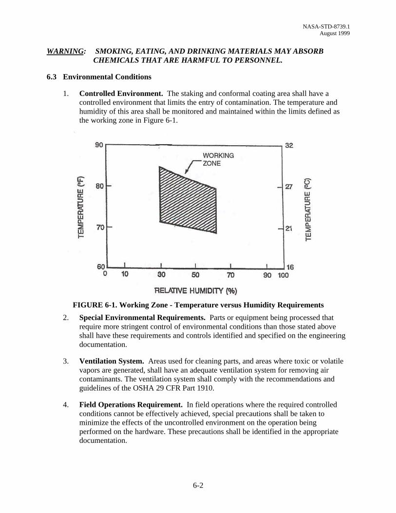
1. Controlled Environment. The staking and conformal coating area shall have acontrolled environment that limits the entry of contamination. The temperature andhumidity of this area shall be monitored and maintained within the limits defined asthe working zone in Figure 6-1.
FIGURE 6-1. Working Zone - Temperature versus Humidity Requirements
2. Special Environmental Requirements. Parts or equipment being processed thatrequire more stringent control of environmental conditions than those stated aboveshall have these requirements and controls identified and specified on the engineeringdocumentation.
3. Ventilation System. Areas used for cleaning parts, and areas where toxic or volatilevapors are generated, shall have an adequate ventilation system for removing aircontaminants. The ventilation system shall comply with the recommendations andguidelines of the OSHA 29 CFR Part 1910.
4. Field Operations Requirement. In field operations where the required controlledconditions cannot be effectively achieved, special precautions shall be taken tominimize the effects of the uncontrolled environment on the operation beingperformed on the hardware. These precautions shall be identified in the appropriatedocumentation.
NASA-STD-8739.1 August 1999
6-3
5. Lighting Requirements. Light intensity shall be a minimum of 1077 Lumens persquare meter (Lm/m2) (100 foot - candles ) on the surface being staked, conformallycoated, or inspected. Supplemental lighting may be used to achieve the required levels.
6.4 Electrostatic Discharge Requirements
Electrostatic Discharge (ESD) requirements shall be in accordance with NASA-STD-8739.7.
6.5 Tool and Equipment Control
1. Each supplier shall:
a. Select tools to be used in staking, conformal coating, and in work preparationareas appropriate to their intended function.
b. Clean and properly maintain all tools and equipment.
c. Examine all elements of tools used in polymeric applications for physicaldamage.
d. Prohibit unauthorized, defective, or uncalibrated tools in the work area.
e. Document detailed operating procedures and maintenance schedules for tools andequipment requiring calibration or set up. Maintain records of tool andequipment calibration and functional testing.
2. The supplier shall have a documented calibration system in accordance withANSI/NCSL Z540-1-1994. The minimum standard shall be:
a. Measurement standards used for calibrating tools must be traceable to theNational Institute of Standards and Technology. Calibration of tools shall beperformed in an environment compatible with the environmental requirements ofthe tools.
b. Calibration intervals shall be based on the type of tool and records of the tool’scalibration. Intervals may be lengthened or shall be shortened on the basis ofstability demonstrated over previous calibration periods.
c. Procedures shall be generated and utilized for the calibration of all tooling statedherein. Procedures shall include, as a minimum, standards to be used, parametersto be measured, accuracy, tolerances, environmental factors, and steps in thecalibration process. The procedures may be manufacturer’s specifications ifjudged adequate, and need not therefore be rewritten, but must be documented.
d. Records shall be maintained that document the data for each tool calibration.
NASA-STD-8739.1 August 1999
6-4
e. Tools shall be labeled to indicate, as a minimum:
(1) Date of calibration.
(2) Calibration due date.
(3) Any limitation of use. If placing the label directly on the tool is notpractical, then the label shall be affixed to the tool container.
(4) The identification of the organization performing the calibration.
(5) Tool identification.
(6) Traceability on the tool to the container if the container contains thecalibration label.
f. Power tools used during the staking and conformal coating process shall complyto the tool requirements herein and have a three-wire grounded power cord or bedouble insulated. The area making contact with the workpiece shall be grounded.When measured from the workpiece contact point to ground, the resistance shallnot exceed 2.0 ohms and the potential difference shall not exceed 2 millivoltsroot mean square (RMS) using methods indicated on the supplier’s engineeringdocumentation.
3. The supplier’s process documentation for tool control is subject to review andapproval by the procuring NASA Center. Suppliers may elect to use tools notmentioned in this Standard provided the engineering documentation is reviewed andapproved by the procuring NASA Center.
6.6 Staking and Conformal Coating Material Selection
1. Staking and conformal coating materials shall be selected from the Qualified ProductsList (QPL) of MIL-I-46058 or other sources specified in writing by the procuringNASA Center. Staking materials are to be applied as identified on the engineeringdocumentation. To facilitate examination for coverage, conformal coating materialswith a fluorescent indicator are preferred.
CAUTION: ULTRAVIOLET (UV) SENSITIVE EQUIPMENT MAY BE ADVERSELYAFFECTED BY USING FLUORESCENT INDICATORS.
2. All materials used in vacuum or low-pressure compartments shall not release greaterthan 1.0 percent total mass loss (TML) or 0.1 percent collected volatile condensablematerial (CVCM) when tested in accordance with ASTM-E-595. All materials used inhabitable areas of spacecraft, stowed equipment, and experiments shall be evaluatedfor flammability, odor, and offgassing characteristics in accordance with NHB 8060.1.Materials used shall be subjected to NASA approval. All material shall be selected toconform to the project contamination control requirements plan.
NASA-STD-8739.1 August 1999
6-5
6.7 Material Storage
1. Shelf Life.
a. Shelf Life Stickers. Material storage shall be controlled by shelf life stickersattached to each material container.
b. Expired Shelf Life. Staking and conformal coating material shall not be used ifthe shelf life has expired. Shelf life extension may be granted on anindividualized basis when adequate data is provided to the procuring supplier inadvance of actual use.
c. Shelf Life. The material shelf life shall be as stated by the manufacturer and inaccordance with the manufacturer’s specifications governing the usable life ofthe product.
2. Materials.
a. Solvents. All cleaning and diluent solvents shall be stored in accordance withimposed safety regulations.
b. Staking and Conformal Coating Materials. Materials shall be stored inaccordance with the manufacturer’s recommendations. All stored containers shallbe sealed.
c. Moisture Sensitive Material. Many materials are hygroscopic or moisturesensitive. Their storage shall be such as to minimize moisture exposure. All suchmaterial shall be stored in a dry nitrogen atmosphere whenever possible.
d. Material in Use. The staking and conformal coating material shall be free offoreign matter and shall not show any signs of apparent deterioration or priorcatalytic action.
3. Records.
a. Purchase Date Recording. Records of manufacturing date, lot number,receiving date, and manufacturer’s certification of compliance of each materialshipment shall be maintained.
b. Container Markings. Material containers shall be marked in accordance withthe following:
(1) Manufacturer’s identification.
(2) Manufacturer’s product designation.
(3) Batch number (if applicable).
(4) Storage temperature range (if applicable).

NASA-STD-8739.1 August 1999
6-6
(5) Expiration date of guaranteed product life or use.
(6) Caution notes (where applicable).
4. Storage Requirements. The conditions for material storage shall be as specified bythe manufacturer.
6.8 Inspection Optics
Visual inspection shall be performed using magnification aids conforming to the following:
1. Inspection magnification aids that permit simultaneous viewing with both eyes arepreferred but single eye viewing devices are acceptable.
2. Magnification aids shall be capable of rendering true colors, proportional dimensions,and adequate resolution at the chosen magnification to perform the specifiedinspection.
3. The light source shall provide shadowless illumination of the area being viewed.
4. Magnification aids shall utilize only glass optical elements.
6.9 In-Process Storage and Handling
1. Each supplier performing staking and conformal coating operations shall develop andimplement requirements and procedures that control conditions to prevent damage toand degradation of parts and deliverable items. In particular, means shall be providedto prevent damage or contamination of printed wiring terminating areas, terminals,connectors, wire ends, and part leads during handling or storage. Containers shall becompatible with materials stored therein.
2. Contact with bare hands shall be avoided. When handling metal surfaces, printedwiring terminating areas, terminals, connectors, wire ends, or part leads isunavoidable, clean, lint free gloves or finger cots shall be used. Gloves or finger cotsshall not generate a static charge.
6.10 Solvents
1. The solvents or aqueous cleaners used to remove grease, oil, dirt, flux, and otherdebris shall be selected for their ability to remove both ionic and nonioniccontamination. The solvents or cleaners used shall not degrade the materials or partsbeing cleaned. A list of approved solvents and cleaners is provided in Table 6-1.Mixtures of the approved solvents may be used. Solvent containers shall be properlylabeled. The use of any other solvents requires the approval of the procuring NASACenter and shall be identified in the supplier’s process documentation. MSDS’s forsolvents and cleaners shall be available for personnel review at the work area. Also seeparagraph 6.3-3.
NASA-STD-8739.1 August 1999
6-7
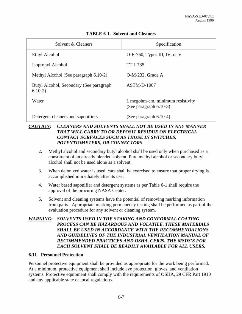
TABLE 6-1. Solvent and Cleaners
Solvent & Cleaners Specification
Ethyl Alcohol
Isopropyl Alcohol
Methyl Alcohol (See paragraph 6.10-2)
Butyl Alcohol, Secondary (See paragraph6.10-2)
Water
Detergent cleaners and saponifiers
O-E-760, Types III, IV, or V
TT-I-735
O-M-232, Grade A
ASTM-D-1007
1 megohm-cm, minimum resistivity(See paragraph 6.10-3)
(See paragraph 6.10-4)
CAUTION: CLEANERS AND SOLVENTS SHALL NOT BE USED IN ANY MANNERTHAT WILL CARRY TO OR DEPOSIT RESIDUE ON ELECTRICALCONTACT SURFACES SUCH AS THOSE IN SWITCHES,POTENTIOMETERS, OR CONNECTORS.
2. Methyl alcohol and secondary butyl alcohol shall be used only when purchased as aconstituent of an already blended solvent. Pure methyl alcohol or secondary butylalcohol shall not be used alone as a solvent.
3. When deionized water is used, care shall be exercised to ensure that proper drying isaccomplished immediately after its use.
4. Water based saponifier and detergent systems as per Table 6-1 shall require theapproval of the procuring NASA Center.
5. Solvent and cleaning systems have the potential of removing marking informationfrom parts. Appropriate marking permanency testing shall be performed as part of theevaluation procedure for any solvent or cleaning system.
WARNING: SOLVENTS USED IN THE STAKING AND CONFORMAL COATINGPROCESS CAN BE HAZARDOUS AND VOLATILE. THESE MATERIALSSHALL BE USED IN ACCORDANCE WITH THE RECOMMENDATIONSAND GUIDELINES OF THE INDUSTRIAL VENTILATION MANUAL OFRECOMMENDED PRACTICES AND OSHA, CFR29. THE MSDS’S FOREACH SOLVENT SHALL BE READILY AVAILABLE FOR ALL USERS.
6.11 Personnel Protection
Personnel protective equipment shall be provided as appropriate for the work being performed.At a minimum, protective equipment shall include eye protection, gloves, and ventilationsystems. Protective equipment shall comply with the requirements of OSHA, 29 CFR Part 1910and any applicable state or local regulations.

NASA-STD-8739.1 August 1999
7-1
CHAPTER 7 - CLEANLINESS REQUIREMENTS
7.1 General
All cleaning procedures shall be specified in the supplier’s process documentation.
1. Monitoring. The effectiveness of the cleaning process depends upon the properexecution of the approved cleaning procedure. To assure the effectiveness of thecleaning method, a system for monitoring the purity of the cleaning solvents shall beestablished. Solvents used in degreasing systems shall be periodically checked andreplaced when contamination exceeds established levels.
2. Compatibility of Solvent With Hardware. The cleaning solvent shall be chemicallybenign to the hardware and in accordance with Table 6-1. The solvent used shall notdegrade the reliability of the hardware being cleaned.
3. Protection of Unsealed Parts. Unsealed parts shall not be completely immersed inthe cleaning solvent. Hardware containing unsealed parts shall be immersed in thesolvent only after these parts have been sealed or masked prior to cleaning.
4. Ultrasonic Cleaning. Ultrasonic cleaning shall not be used for cleaning assembliesthat contain electronic parts.
5. Rework Cleaning. The rework area shall be cleaned and dried prior to application ofrework staking and conformal coating. Conformal coated assemblies shall not beimmersion cleaned.
7.2 Cleanliness Testing
Cleanliness testing is used to monitor the effectiveness of PWA cleaning processes. All PWA’sshall be tested prior to conformal coating.
1. Two basic test methods are recommended.
a. Resistivity of solvent extract (paragraph 7.5).
b. Sodium chloride (NaCl) salt equivalent ionic contamination test (paragraph 7.6).
2. Other test methods must be approved by the procuring supplier before use.
7.3 Testing Frequency
1. Testing shall be performed with sufficient frequency to ensure compliance with therequirements of paragraph 7.4 test limits. At a minimum, this shall consist of once pershift, and immediately prior to changing the cleaning solvent solution.

NASA-STD-8739.1 August 1999
7-2
2. It is recommended that statistical process control methods be used to controlcontinuous solvent cleaning processes. Records of relevant readings shall bemaintained for early detection of a trend towards an out-of-specification condition.
3. In the event that the result of a test is unacceptable, all the PWA’s that were cleanedbetween the previous passed test and this failed test are considered unacceptable.
4. Failed PWA’s shall not be recleaned until appropriate corrective actions have beenperformed on the cleaning system to ensure its correct operation.
7.4 Test Limits
1. Resistivity Of Solvent Extract. The resistivity of the solvent extract shall have afinal value greater than 2,000,000 ohm-cm.
2. Sodium Chloride Salt Equivalent Ionic Contamination Test. The final value forthis test must be less than 1.55 micrograms per sq. cm (10 micrograms per squareinch) of PWB surface area.
7.5 Resistivity of Solvent Extract
Solvent extract resistivity shall be measured as follows (also, see Table 7-1):
1. Prepare a test solution of 75 percent by volume isopropyl alcohol and 25 percent byvolume deionized water. Pass this solution through a mixed bed deionizer cartridge.After passage through the cartridge, the resistivity of the solution shall be greater than6 x 106 ohm-cm (conductivity less than 0.166 micromhos/cm).
2. Clean a funnel, a wash bottle, and a container with a portion of this test solution.Measure out 1.55 ml for each square centimeter (10 ml for each square inch) of PWAarea on both sides of the PWA.
3. Slowly, direct the test solution in a fine stream onto both sides of the PWA until all themeasured solution is used.
4. The resistivity of the solvent extract shall be determined by using a resistivity meter.
7.6 Sodium Chloride Salt Equivalent Ionic Contamination Test
Sodium chloride salt equivalent ionic contamination shall be measured as follows (also, seeTable 7-1):
1. The sodium chloride salt equivalent ionic contamination test must use a solution of 75percent isopropyl alcohol and 25 percent deionized water. This solution must beverified for correct composition upon initial use and every 4 hours during a shift. Thetime limit may be extended when the results of data provide definite indications thatsuch actions will not adversely affect the results of the test.
NASA-STD-8739.1 August 1999
7-3
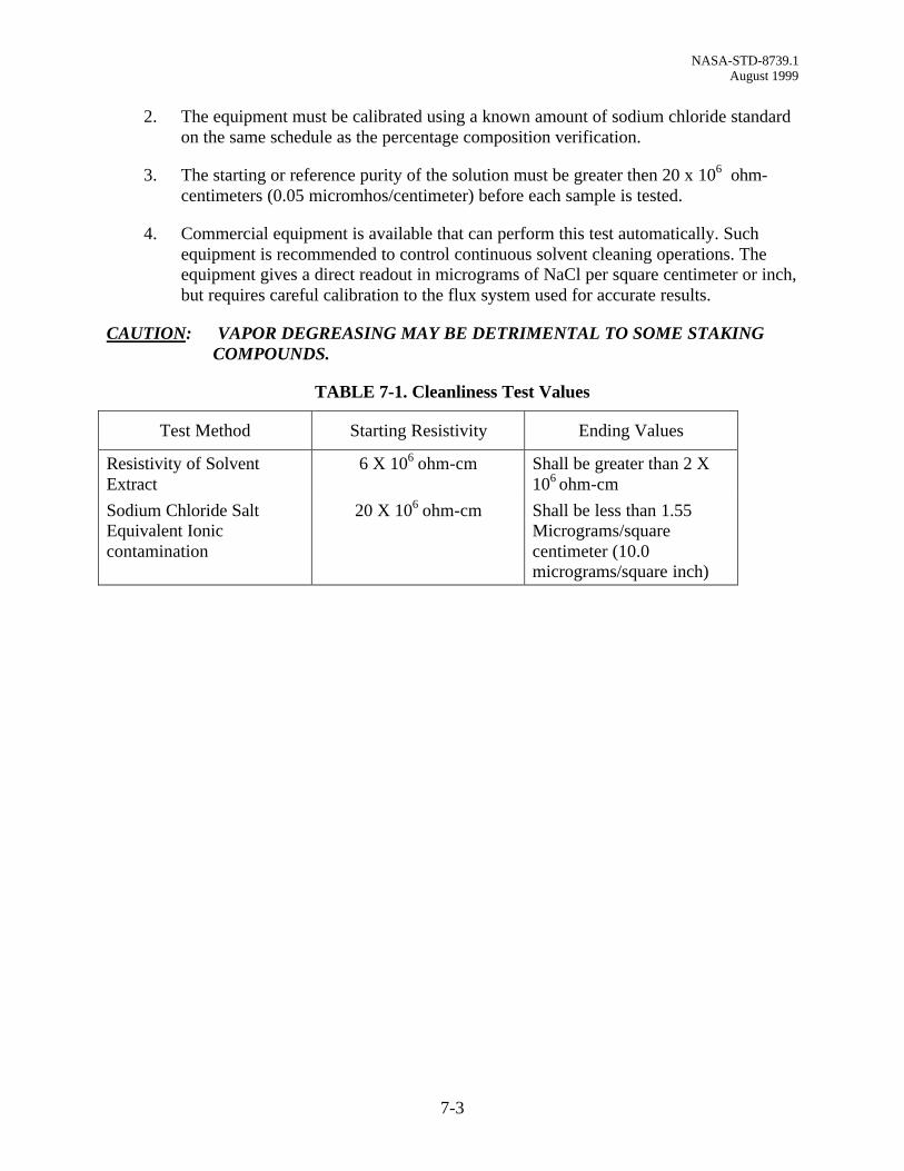
2. The equipment must be calibrated using a known amount of sodium chloride standardon the same schedule as the percentage composition verification.
3. The starting or reference purity of the solution must be greater then 20 x 106 ohm-centimeters (0.05 micromhos/centimeter) before each sample is tested.
4. Commercial equipment is available that can perform this test automatically. Suchequipment is recommended to control continuous solvent cleaning operations. Theequipment gives a direct readout in micrograms of NaCl per square centimeter or inch,but requires careful calibration to the flux system used for accurate results.
CAUTION: VAPOR DEGREASING MAY BE DETRIMENTAL TO SOME STAKINGCOMPOUNDS.
TABLE 7-1. Cleanliness Test Values
Test Method Starting Resistivity Ending Values
Resistivity of SolventExtract
6 X 10⁶ ohm-cm Shall be greater than 2 X10⁶ ohm-cm
Sodium Chloride SaltEquivalent Ioniccontamination
20 X 106 ohm-cm Shall be less than 1.55Micrograms/squarecentimeter (10.0micrograms/square inch)
NASA-STD-8739.1 August 1999
8-1
CHAPTER 8 - PREPARATION FOR STAKING AND CONFORMAL COATING
8.1 Surface Preparation
Surface preparation varies with the type of material and substrate. For materials, substrates, orcombinations not specifically addressed in this Standard, special instructions shall be generatedin accordance with paragraph 1.4.
8.2 Masking
1. Material. Areas to be kept free of conformal coating material shall be masked withapproved tape, covers, or other suitable masking material or devices. Masking materialshall be compatible with the PWA being coated. Do not use anti-static masking tapescontaining conductive adhesive on PWB conductor patterns.
CAUTION: TAPES MAY CONTAIN METALLIC OR METALLIZED POLYMERICMATERIAL THAT CAN CAUSE ELECTRICAL SHORTS OR CORROSION.
NOTE: PRECAUTIONS MUST BE TAKEN TO ASSURE THAT NO RESIDUES ARELEFT WHEN THE MASKING MATERIAL IS REMOVED.
2. Masking Methods. The method of conformal coating application may dictatecompleteness of masking. For instance, dip conformal coating application requiresmore thorough masking than brush conformal coating application, which in turnrequires better masking than spray conformal coating application.
3. Masking for Paraxylene Conformal Coating. Unsealed parts and areas not to becoated shall be properly masked to prevent paraxylene vapors from penetrating minuteopenings. Masking materials must be compatible with the vacuum deposition system.
8.3 Priming
1. Conformal Coatings Requiring Primer. Silicone and paraxylene conformalcoatings usually require a primer, whereas most other conformal coatings may not.When a primer is used, it shall be of a material recommended by the samemanufacturer that produced the conformal coating material and shall be applied andcured in accordance with the manufacturer’s instruction.
2. Silicone and Paraxylene Conformal Coating Requirements. For those silicone andparaxylene conformal coatings requiring priming, the primer shall be applied inaccordance with the manufacturer’s instructions. Any excess buildup must beremoved.
3. Repriming Requirements. Most primers are effective only for a specified period oftime with well-protected storage. If, after priming, subsequent conformal coating hasnot been applied within the manufacturer’s recommended elapsed time, repriming ismandatory.
NASA-STD-8739.1 August 1999
8-2
NOTE: SOME SURFACE PRIMERS WILL DAMAGE CERTAIN TYPES OFMATERIALS. REFER TO MANUFACTURERS’ SPECIFICATIONS FORTHE SPECIFIC TYPE OF SURFACE PRIMER RECOMMENDED FORUSE.
8.4 Material Preparation
Staking and conformal coating material shall be mixed and prepared according to themanufacturer’s instructions or the appropriate process document. It must be verified, prior tousage, that materials have not exceeded their shelf life. General information and requirements onmaterials follows:
1. Single-Component Materials. Materials that are supplied as a single part mayrequire stirring because of settling of fillers or other ingredients in the system.
2. Multicomponent Materials. Multicomponent materials shall be thoroughly mixeduntil the mixture is smooth and homogeneous and shall be used within the workinglife limit. Frozen premixes do not need mixing, but will have working life limits afterbeing thawed.
3. Premixing of Fillers. If filler is to be added, it shall be premixed into the lessmoisture-sensitive part before final mixing. Highly absorbent fillers shall not be used.
4. Moisture Removal. Fillers are normally hygroscopic and should be oven baked toremove absorbed moisture before being added to resins.
5. Order of Mixing. When used, accelerators (or catalysts) shall be mixed in last toextend working life as much as possible. Mixing shall be carefully conducted tominimize entrapped air. High-solid materials or high-viscosity materials may bedeaerated to remove trapped air. Be aware of the possibility of losing the volatileingredients, if any, in the deaeration process.
6. Mix Record. A record of each mix batch date and procedure shall be maintained
7. Spray Applications. In spray application, viscosity of conformal coatings shall beclosely observed and controlled by adding solvents as necessary to preserve the bestsprayable viscosity. Solvent addition shall not be used to extend the working life of thematerial.
8. Containers. In all mixing operations, nonabsorbent plastic, glass, or metal containersand stirrers shall be used. Containers with seams and crevices that will trap unmixedmaterials shall not be used. Metal stirrers shall not be used when materials are mixedin plastic containers.
9. Material Condition. Materials shall not be used that exhibit any evidence ofexcessive crystallization, surface skinning, or gelling.
10. Silicones. All silicone operations shall be segregated from other material operations.
NASA-STD-8739.1 August 1999
8-3
11. Working Life. The working life (pot life) of the material shall begin immediatelyafter mixing.
8.5 Witness Sample
A witness sample shall be maintained for each mixed batch. The witness sample shall beprocessed at the same time and under the same conditions as the PWA. Witness samples shall bemaintained for 5 years, or as specified by the contract. Acceptance of the witness sample shall beindicated on the mix record. The witness sample shall be identified and stored under controlledconditions of temperature and humidity.
8.6 Preparation For Conformal Coating Control Specimens
A control board specimen, preferably a scrapped PWB, shall be coated concurrently with theregular PWA conformal coating operation whenever a new lot of material or a newly mixedbatch of material is prepared. The control PWB specimens shall be used for tests and analyses toavoid damage or destruction of the production boards. The control assemblies shall be marked asso and stored separately from the process assemblies.
NASA-STD-8739.1 August 1999
9-1
CHAPTER 9 - STAKING
9.1 Purpose
The main purpose for staking is to protect and support parts that may be damaged by vibration,shock, or handling.
9.2 Staking
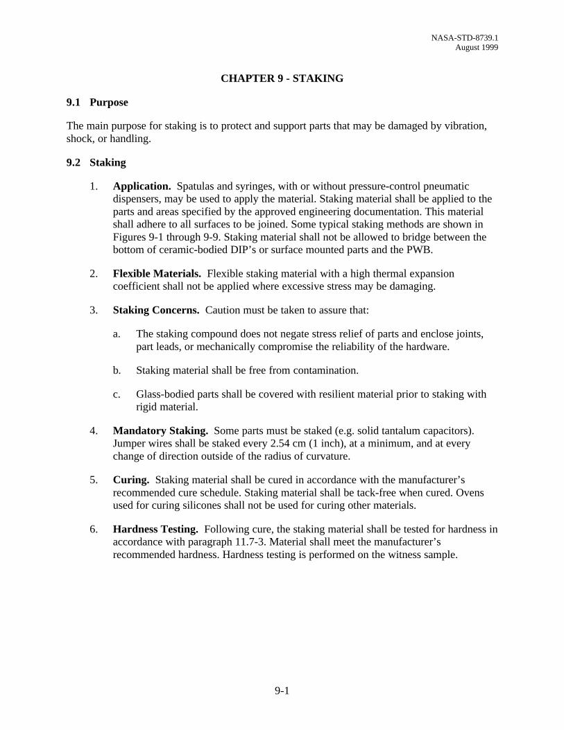
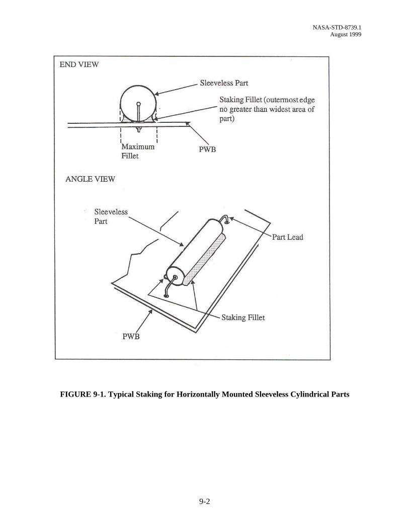
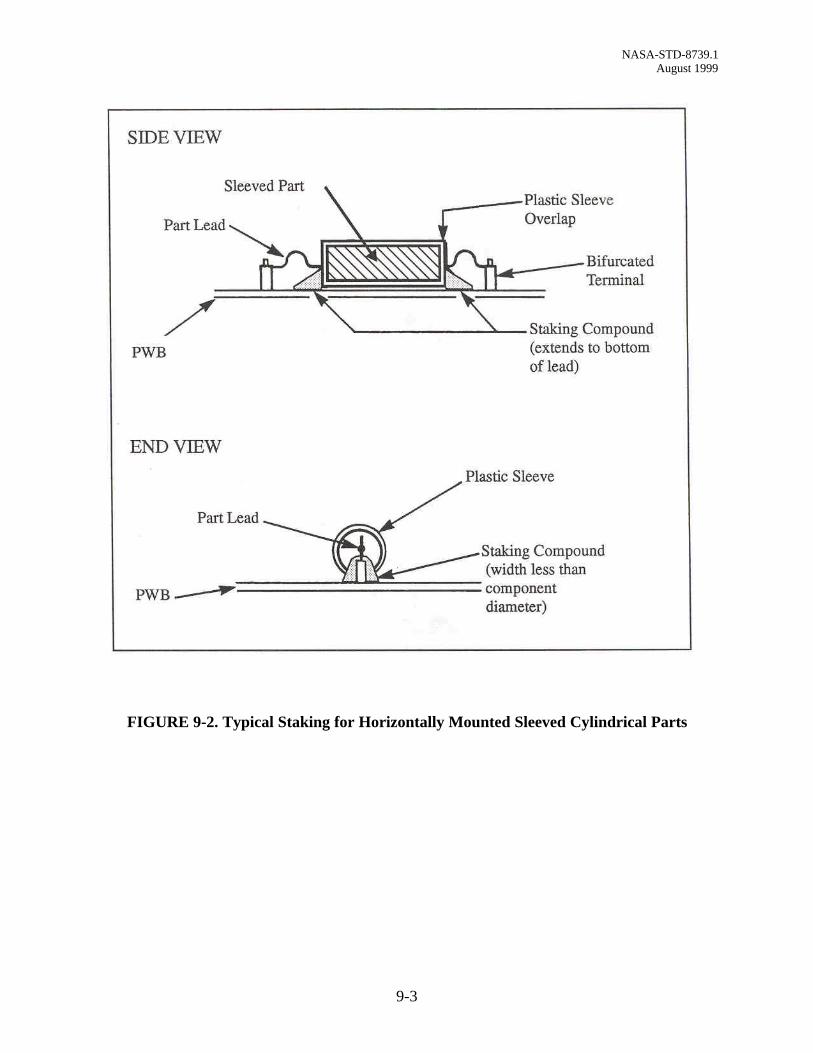
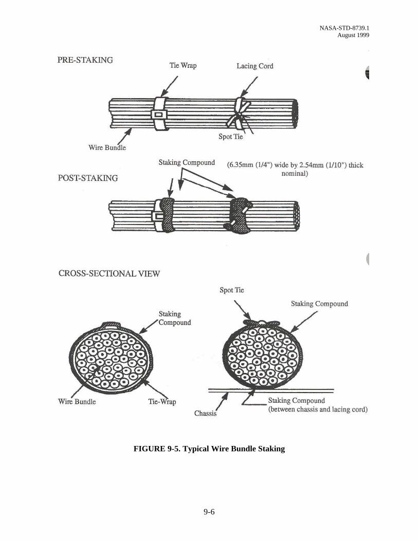
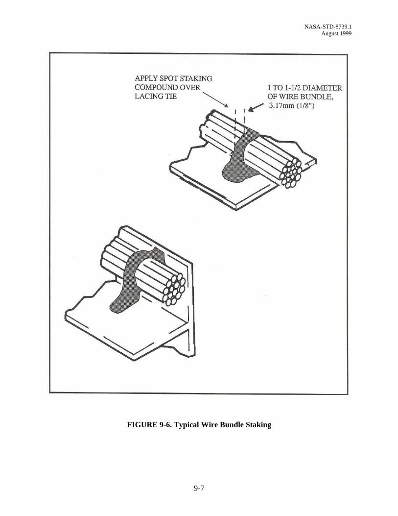
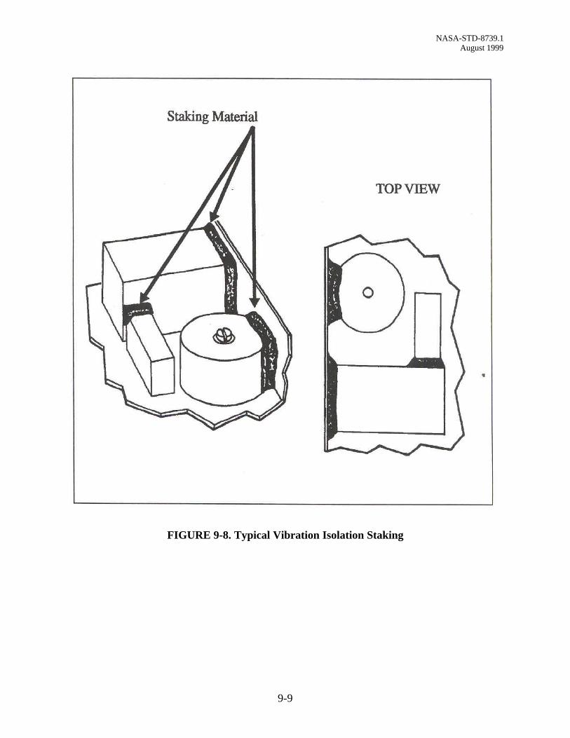
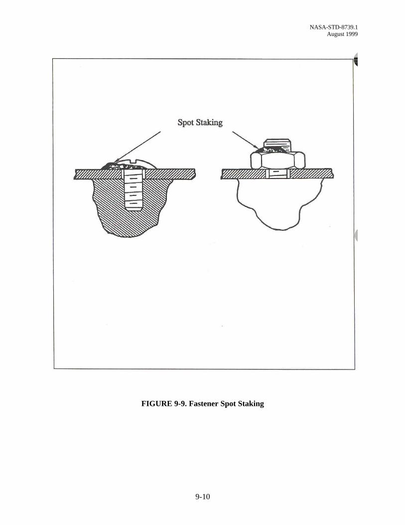
1. Application. Spatulas and syringes, with or without pressure-control pneumaticdispensers, may be used to apply the material. Staking material shall be applied to theparts and areas specified by the approved engineering documentation. This materialshall adhere to all surfaces to be joined. Some typical staking methods are shown inFigures 9-1 through 9-9. Staking material shall not be allowed to bridge between thebottom of ceramic-bodied DIP’s or surface mounted parts and the PWB.
2. Flexible Materials. Flexible staking material with a high thermal expansioncoefficient shall not be applied where excessive stress may be damaging.
3. Staking Concerns. Caution must be taken to assure that:
a. The staking compound does not negate stress relief of parts and enclose joints,part leads, or mechanically compromise the reliability of the hardware.
b. Staking material shall be free from contamination.
c. Glass-bodied parts shall be covered with resilient material prior to staking withrigid material.
4. Mandatory Staking. Some parts must be staked (e.g. solid tantalum capacitors).Jumper wires shall be staked every 2.54 cm (1 inch), at a minimum, and at everychange of direction outside of the radius of curvature.
5. Curing. Staking material shall be cured in accordance with the manufacturer’srecommended cure schedule. Staking material shall be tack-free when cured. Ovensused for curing silicones shall not be used for curing other materials.
6. Hardness Testing. Following cure, the staking material shall be tested for hardness inaccordance with paragraph 11.7-3. Material shall meet the manufacturer’srecommended hardness. Hardness testing is performed on the witness sample.
NASA-STD-8739.1 August 1999
9-2
FIGURE 9-1. Typical Staking for Horizontally Mounted Sleeveless Cylindrical Parts
NASA-STD-8739.1 August 1999
9-3
FIGURE 9-2. Typical Staking for Horizontally Mounted Sleeved Cylindrical Parts

NASA-STD-8739.1 August 1999
9-4
Figure 9-3. Typical Staking of a Single Vertically Mounted Rectangular Part
NASA-STD-8739.1 August 1999
9-5
FIGURE 9-4. Typical Staking for an Array of Vertically Mounted Rectangular Parts
NASA-STD-8739.1 August 1999
9-6
FIGURE 9-5. Typical Wire Bundle Staking
NASA-STD-8739.1 August 1999
9-7
FIGURE 9-6. Typical Wire Bundle Staking

NASA-STD-8739.1 August 1999
9-8
FIGURE 9-7. Typical Toroid Staking
NASA-STD-8739.1 August 1999
9-9
FIGURE 9-8. Typical Vibration Isolation Staking
NASA-STD-8739.1 August 1999
9-10
FIGURE 9-9. Fastener Spot Staking
CHAPTER 10 - CONFORMAL COATING
10.1 Purpose
Conformal coatings are intended to provide electrical insulation and environmental protectionthus minimizing the performance degradation to electronic PWA’s by humidity, handling, debris,and contamination. Conformal coating materials may include solvents (diluents), fillers, andcatalysts and/or accelerators, in addition to the basic resin. Some conformal coating materialscome in a one-part form. Vacuum deposition material, including paraxylene, requires a specialconformal coating chamber. Staking shall be performed prior to conformal coating unless it isspecifically stated otherwise on the engineering documentation.
10.2 Conformal Coating Application
1. The PWA’s shall be cleaned and demoisturized within 8 hours before conformalcoating. Demoisturizing shall be defined on the engineering documentation.Demoisturizing may be accomplished by an oven bake at 93°C ± 5.5°C (200F° ±10°F) for a minimum of 4 hours for a PWA or 2 hours for a PWB, or by a vacuumbake at a lower temperature. The time in and out of the oven or chamber and thetemperature shall be recorded.
2. Conformal coating shall be applied using a method that will yield complete coveragewithout excessive filleting or runs. Common coating application methods includespraying, brushing, dipping, or a combination thereof. Chemical Vapor Deposition(CVD) is the process used for paraxylene.
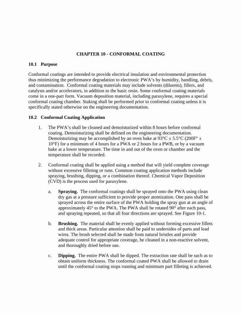
a. Spraying. The conformal coatings shall be sprayed onto the PWA using cleandry gas at a pressure sufficient to provide proper atomization. One pass shall besprayed across the entire surface of the PWA holding the spray gun at an angle ofapproximately 45° to the PWA. The PWA shall be rotated 90° after each pass,and spraying repeated, so that all four directions are sprayed. See Figure 10-1.
b. Brushing. The material shall be evenly applied without forming excessive filletsand thick areas. Particular attention shall be paid to undersides of parts and leadwires. The brush selected shall be made from natural bristles and provideadequate control for appropriate coverage, be cleaned in a non-reactive solvent,and thoroughly dried before use.
c. Dipping. The entire PWA shall be dipped. The extraction rate shall be such as toobtain uniform thickness. The conformal coated PWA shall be allowed to drainuntil the conformal coating stops running and minimum part filleting is achieved.
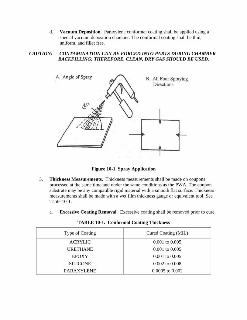
d. Vacuum Deposition. Paraxylene conformal coating shall be applied using aspecial vacuum deposition chamber. The conformal coating shall be thin,uniform, and fillet free.
CAUTION: CONTAMINATION CAN BE FORCED INTO PARTS DURING CHAMBERBACKFILLING; THEREFORE, CLEAN, DRY GAS SHOULD BE USED.
Figure 10-1. Spray Application
3. Thickness Measurements. Thickness measurements shall be made on couponsprocessed at the same time and under the same conditions as the PWA. The couponsubstrate may be any compatible rigid material with a smooth flat surface. Thicknessmeasurements shall be made with a wet film thickness gauge or equivalent tool. SeeTable 10-1.
a. Excessive Coating Removal. Excessive coating shall be removed prior to cure.
TABLE 10-1. Conformal Coating Thickness
Type of Coating Cured Coating (MIL)
ACRYLIC
URETHANE
EPOXY
SILICONE
PARAXYLENE
0.001 to 0.005
0.001 to 0.005
0.001 to 0.005
0.002 to 0.008
0.0005 to 0.002
4. Pre-Cure Examination. Immediately after material application, the uncuredconformal coating shall be examined for:
a. Bubbles and Air Entrapments. These defects shall be broken by vacuum, witha sharp probe, or other appropriate tools.
b. Bridging. Conformal coating material shall not be allowed to bridge betweenthe bottom of ceramic-bodied DIP’s or surface mounted parts and the PWB, orbetween the part lead and the PWB, thereby negating stress relief.
5. Post Cure Examination. After the cure cycle, the conformally coated PWB or PWAshall be examined to assure that the following conditions are met. See Figure 10-2through Figure 10-5 for additional requirements.
a. Conformal coating is uniform in color, thickness, and texture, tack-free, andshows proper adhesion to all coated surfaces.
b. Conformal coating shall cover all areas as specified on the engineeringdocumentation, have a smooth continuous surface, and follow the contours of thePWA. Minor pull back from sharp points and edges is permissible unlessotherwise specified on engineering documentation.
c. Conformal coating is free from contamination.
d. Terminals shall be conformal coating encapsulated, including the insulation gapof the wire, unless it is a solder ball type connection (as in a high voltageconnection). This is normally applied with a brush after the initial conformalcoating application.
e. Conformal coating may bridge between adjacent part leads providing stressreliefs are not negated.
f. Conformal coating shall not exhibit discoloration (due to such things as excessivecuring oven temperature, contamination, etc.).
10.3 Curing
1. Cure Schedule. The conformal coating material shall be cured in accordance with aspecified cure schedule that is compatible with the thermal limitations of the hardware.The conformal coating shall be tack-free when cured.
2. Multiple Conformal Coatings. When multiple conformal coatings of the samematerial are employed, each layer may be partially cured before the next layer isapplied.
3. Curing Silicones. Ovens used for curing silicones shall not be used for curing othermaterials.

4. Humidity Requirements. While high humidity may retard the completion of curing,some materials specifically require a higher-than-ambient relative humidity to cureproperly. Where necessary, an enhanced humidity environment shall be provided asdefined by the engineering documentation.
5. Handling and Storage. After application of the polymeric material, particularlywhen the material is still wet and tacky (during curing cycle), hardware shall behandled and stored in a manner that minimizes exposure to contamination or handlingdamage.
10.4 Cleanup
Conformally coated PWA’s shall be cleaned to remove any maskant, loose debris, or materialthat may damage or degrade its performance.
10.5 Touchup/Rework
Conformally coated assemblies shall be touched up to correct coating coverage deficiencies.Touched up areas will normally not meet the thickness requirement of Table 10-1. Removal andreplacement of conformal coating is considered rework and the procedures shall be documented.
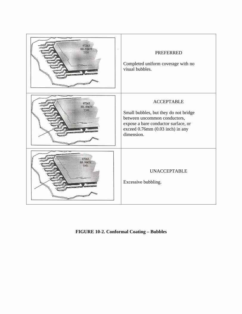
PREFERRED
Completed uniform coverage with novisual bubbles.
ACCEPTABLE
Small bubbles, but they do not bridgebetween uncommon conductors,expose a bare conductor surface, orexceed 0.76mm (0.03 inch) in anydimension.
UNACCEPTABLE
Excessive bubbling.
FIGURE 10-2. Conformal Coating – Bubbles

PREFERRED
No defects.
ACCEPTABLE
Scratch does not expose anyconductive area.
UNACCEPTABLE
Scratch exposes conductive areas.
FIGURE 10-3. Conformal Coating – Scratches
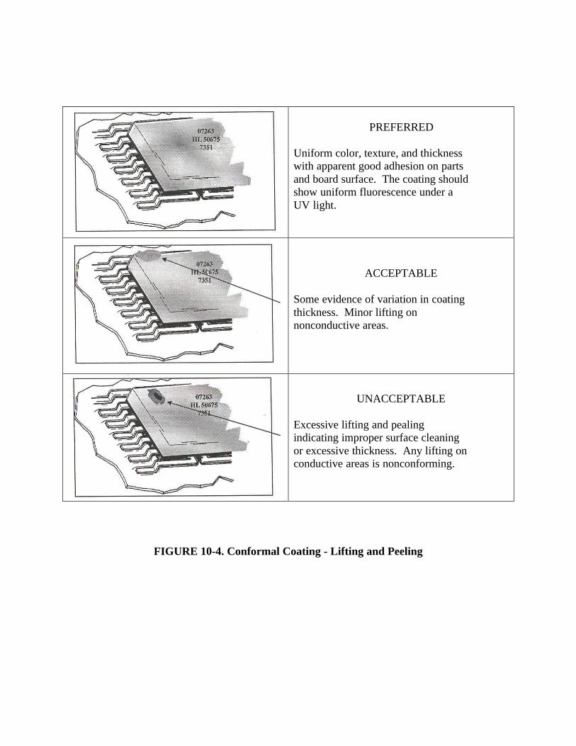
PREFERRED
Uniform color, texture, and thicknesswith apparent good adhesion on partsand board surface. The coating shouldshow uniform fluorescence under aUV light.
ACCEPTABLE
Some evidence of variation in coatingthickness. Minor lifting onnonconductive areas.
UNACCEPTABLE
Excessive lifting and pealingindicating improper surface cleaningor excessive thickness. Any lifting onconductive areas is nonconforming.
FIGURE 10-4. Conformal Coating - Lifting and Peeling
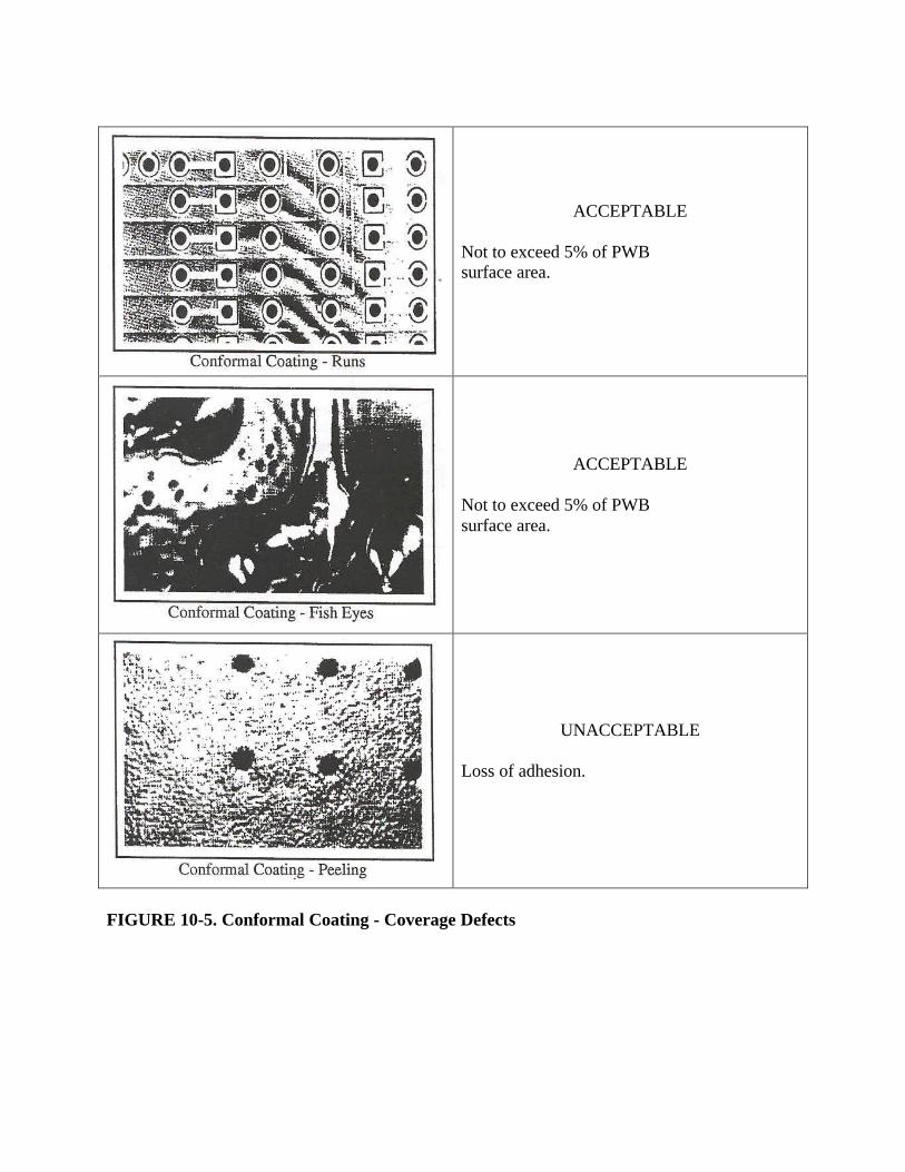
ACCEPTABLE
Not to exceed 5% of PWBsurface area.
ACCEPTABLE
Not to exceed 5% of PWBsurface area.
UNACCEPTABLE
Loss of adhesion.
FIGURE 10-5. Conformal Coating - Coverage Defects

11-1
CHAPTER 11 - QUALITY ASSURANCE
11.1 General
1. Workmanship. Workmanship shall be of a level of quality adequate to assure that theprocessed products meet the performance requirements of the engineeringdocumentation and criteria delineated herein.
2. Inspection. Inspection for acceptability shall be performed on all staked orconformally coated PWA’s to the requirements specified in this Standard. Parts andconductors shall not be physically disturbed to aid inspection.
3. Quality Assurance. The following functions shall be performed:
a. Verify that all tests, inspections, and measurements specified by this Standardhave been performed.
b. Verify that all personnel who stake, coat, or inspect hardware in accordance withthis document have been trained and certified as specified in Chapter 5.
c. Conduct in-process surveillance of all assembly operations to verify that allprocesses and procedures implementing the requirements of this document arecurrent, approved, adequate, and being accurately utilized.
d. Verify that no damage exists on parts and PWB’s prior to their being staked orconformally coated.
e. Verify that the facility cleanliness, environmental conditions, and lightingrequirements of Chapter 6 are being met.
11.2 Magnification Aids
Inspection optics shall conform to the requirements of paragraph 6.8. Visual inspection shall beaided by magnification between 4X and l0X. Additional magnification shall be used as necessaryto resolve suspected anomalies or defects.
11.3 Documentation Verification
Quality assurance personnel shall verify that all required documentation is current and approved.The documentation shall include:
1. Records
a. Results of the visual examination as per paragraph 5.2-1.
b. Evidence of operator and inspector certification as per paragraph 5.5.
c. Material purchase data as per paragraphs 6.7-3a and b.
11-2
d. Mix record as per paragraph 8.4-6.
e. Witness sample as per paragraph 8.5.
f. Demoisturizing as per paragraph 10.2.
2. Procedures
a. Staking or conformal coating program as per paragraphs 4.2 and 5.1.
b. Training and certification program as per paragraph 5.4-3b.
c. Tooling and equipment operating procedures as per paragraph 6.5-le.
d. Calibration system as per paragraph 6.5-2.
e. In-process storage and handling procedures as per paragraph 6.9.
f. Cleaning procedures as per paragraph 7.1.
11.4 Documentation Authorization
Quality assurance personnel shall verify that the following documentation has been approved bythe procuring NASA Center prior to implementation:
1. Special engineering requirements as per paragraph 1.4.
2. Special processes, materials, or parts as per paragraph 4.1-3.
3. Special documents as per paragraph 4.1-3.
4. Departures from requirements as per paragraph 1.5.
5. Repairs as per paragraph 4.3.
6. Process documentation for special tools as per paragraph 6.5-3.
7. Staking and coating materials as per paragraph 6.6.
8. Special cleanliness test methods as per paragraph 7.2-2.
11.5 Verification of Tools, Equipment, and Materials
1. Tools and equipment. Tools and equipment shall be verified for conformance to theapplicable requirements found in paragraph 6.5.
2. Materials. Materials shall conform to the requirements of paragraph 6.6. Controlsshall be implemented to assure that only approved and conforming materials are used.

11-3
Materials not conforming or not required for the operations involved shall be removedfrom the work areas or tagged non-usable.
11.6 Acceptance/Rejection Criteria for Staking
1. Documentation. All acceptance and rejection criteria for staking shall be clearlydefined in the application processing document(s). Reference Figure 9-1 throughFigure 9-9 for typical, acceptable staking requirements.
2. Acceptance Criteria. Staked PWA’s shall exhibit, as a minimum, the followingworkmanship characteristics in order to be judged acceptable:
a. The staking material shall adhere to the intended surfaces as per paragraph 9.2-1.
b. The staking material shall be free from contamination as per paragraph 9.2-3b.
c. Jumper wires shall be staked a minimum of every 2.54 cm (1 inch) and everychange of direction, outside of the radius of curvature as per paragraph 9.2-4.
d. All axial lead solid slug tantalum capacitors shall be staked as per paragraph 9.2-4.
e. The staking material shall be tack-free when cured as per paragraph 9.2-5.
f. Staking material meets the hardness requirements as per paragraph 9.2-6.
3. Rejection Criteria. The following are some characteristics of unsatisfactoryconditions, any of which is cause for rejection.
a. Staking material used after shelf life expiration as per paragraph 6.7-lb.
b. Staking material bridges between the PWB and the bottom of the DIP’s orflatpacks as per paragraph 9.2-1.
c. Staking material fills the stress relief areas as per paragraph 9.2-3a.
d. Staking material encloses the part lead as per paragraph 9.2-3a.
e. Rigid staking has been applied directly to glass bodied parts as per paragraph9.2-3c.
11.7 Inspection Methods for Staking
1. Workmanship requirements shall be verified by visual inspection using 4X to l0Xpower magnification. Higher magnification may be used, as necessary, to inspectsuspected anomalies or defects.
2. Tackiness and Adhesion. Gentle finger pressure shall be used to inspect fortackiness and adhesion. For this purpose, lint-free gloves or finger cots shall be worn.
11-4
3. Hardness. When applicable, hardness shall be measured in accordance with ASTM-D-2240.
11.8 Acceptance/Rejection Criteria for Conformal Coating
1. Documentation. All acceptance and rejection criteria for conformal coating shall beclearly defined in the application processing document(s). Reference Figure 10-2through Figure 10-5 for conformal coating acceptance and rejection criteria.
2. Acceptance Criteria. Conformally coated PWA’s shall exhibit, as a minimum, thefollowing workmanship characteristics to be acceptable:
a. Unless otherwise specified by the approved engineering documentation, theconformal coating, when measured in flat unencumbered areas of the board, orpreferably on the witness coupon, shall have a thickness appropriate for theconformal coating material being used as per paragraph 10.2-3.
b. Conformal coating shall be uniform in color and texture as per paragraph 10.2-5a.
c. Conformal coating shall be tack-free when cured as per paragraph 10.2-5a.
d. Conformal coating shall adhere to all coated surfaces as per paragraph 10.2-5a.
e. Conformal coating shall have a smooth continuous surface and follow thecontours of the PWA as per paragraph 10.2-5b.
f. Conformal coating shall be uniform in thickness as specified in Table 10-1 or onengineering documentation except in touched-up areas as per paragraph 10.5.
g. Conformal coating shall cover all areas as specified on the engineeringdocumentation. Pull back from sharp points and edges shall be permitted unlessotherwise specified as per paragraph 10.2-5b.
h. Conformal coating shall be free of contamination as per paragraph 10.2-5c.
i. Each terminal without a solder ball shall be conformal coating encapsulated toinclude the insulation gap of the wire as per paragraph 10.2-5d.
j. Conformal coating material that bridges between adjacent part leads is acceptableas per paragraph 10.2-5e.
3. Rejection Criteria. The following are some characteristics of unsatisfactoryconditions, any of which is cause for rejection:
a. Conformal coating material used after shelf life expiration as per paragraph6.7-1b.
11-5
b. Conformal coating bridges stress relief areas thereby negating stress relief as perparagraph 10.2-4b.
c. Conformal coating bridges between the PWB and the bottom of DIP’s andflatpacks as per paragraph 10.2-4b.
d. Conformal coating exhibits tackiness or soft spots as per paragraph 10.2-5a.
e. Pinholes, blistering, scratches, whitish spots (measling), wrinkling, or cracking asper paragraph 10.2-5a and paragraph 10.2-5b.
f. Any signs of contamination (e.g., flux, loose particles, or foreign material) as perparagraph 10.2-5c.
g. Discolored conformal coating as per paragraph 10.2-5f.
h. Bubbles or bare spots bridging two electrically conductive elements as perFigure 10-2.
i. Bubbles larger than 0.76 mm (0.03 inch) in any dimension as per Figure 10-2.
j. Conformal coating exhibits lifting or peeling as per Figure 10-4.
k. Conformal coating exhibits excess runs, fish eyes, or peeling as per Figure 10-5.
11.9 Inspection Methods for Conformal Coating
1. Visual Inspection of Workmanship and Adhesion Requirements. Workmanshipand adhesion requirements shall be verified by visual inspection using 4X to l0Xpower magnification. Higher magnification may be used, as necessary, to verifysuspected anomalies or defects.
2. UV-Light Inspection. When fluorescent conformal coating materials are used,coverage and location shall be determined by UV-light examination.
3. Conformal Coating Thickness Inspection. Conformal coating thickness shall bedetermined using a wet film thickness gauge, micrometer, or other tool on flat surfacesof the PWB, PWA, or preferably, the coupon required by paragraph 10.2-3.
4. Tackiness and Soft Spots. Gentle finger pressure shall be used to inspect fortackiness and soft spots. For this purpose, lint-free gloves or finger cots shall be worn.
A-1
APPENDIX ACONFORMAL COATING PROBLEMS
The following are the major problems encountered in the conformal coating process:
1. Conformal Coating Thickness. Conformal coating thickness can be critical to theproper function of a PWA. If a coating is too thin, proper coverage is impossible; if acoating is too thick, it may create excessive stresses on solder joints and components(particularly glass-bodied components). Controlling coating thickness is of specialimportance with rigid coating materials (e.g., epoxies and some of the urethanes)because the residual stresses associated with an excessively thick application of thesematerials are much greater than with flexible coating materials (such as silicones andsome urethanes).
The thickness of a conformal coating can best be controlled by controlling the materialviscosity during application. Where permitted, diluent solvents can be used to controlviscosity. A multiple-coating process can also be used to attain more uniformthickness. Excessive filleting of adjacent components, caused by surface tension, maynecessitate use of a brush to remove the excess.
2. Coverage -- Points and Edges. Liquid coatings, because of gravity and their surfaceenergy, tend to pull away from sharp points and edges which are often formed inconductors needing the most coverage. Inadequately protected conductors exposed toatmospheric humidity or condensing moisture can easily develop circuitrymalfunctions.
This problem can be alleviated by using a multiple-coat process with some dryingbetween coat applications or by using an initial coat with a filler that will reduce thetendency of the coating to pull away from points and edges better. Vacuum depositionof paraxylylene is the best method for covering points and edges.
3. Bubbles. Bubbles normally originate from air trapped underneath components and atsolder joints. When bubbles bridge uncommon conductors, entrapped moisture orother contaminants may reduce insulation resistance or cause shorts and possiblearcing.
Bubbling may be controlled by various means. The angle at which an assembly isdried, cured, or dipped is important in preventing bubble formation. The best angle forspraying conformal coating is usually 45° to the PWA. The drying and cure schedulecan also affect bubble formation. Sometimes air cure is needed to permit solventevaporation; sometimes immediate thermal cure is more desirable because of lowermaterial viscosity caused by higher temperature. Spray coating, being more thinlyapplied, is not as susceptible to bubbling caused by solvent and air entrapment as aredip coating and brush coating. For thicker coating applications, degassing in a vacuumchamber will remove entrapped air.

NASA TECHNICAL STANDARD IMPROVEMENT PROPOSAL(SEE INSTRUCTION - REVERSE SIDE)
1. DOCUMENT NUMBER 2. DOCUMENT TITLE
3. NAME OF SUBMITTING ORGANIZATION
4. ADDRESS (Street, City, State, ZIP Code)
5. PROBLEM AREAS
a. Paragraph Number and Wording
b. Recommended Wording:
c. Rational for Recommendation:
6. REMARKS
7. NAME OF SUBMITTER 8. TELEPHONE NO. 9. DATE
INSTRUCTIONS
In a continuing effort to make our NASA Standards better we invite all holders to use this formfor submitting comments and suggestions for improvements. All users of NASA documents areinvited to provide suggestions. The form may be detached and mailed. In block 5, be as specificas possible about particular problem areas, such as wording changes, which would alleviate theproblems. Enter in block 6 any remarks not related to a specific paragraph of the document.
An acknowledgment will be mailed to the submitter within 30 days. Supporting data shouldaccompany any recommendations for changes.
NOTE: This form may not be used to request copies of documents, nor to request waivers,deviations, or clarification of Standard requirements on current contracts. Comments submittedon this form do not constitute or imply authorization to waive any portion of the referenceddocument(s) or to amend contractual requirements.
Proposal may be submitted to:
NASA HeadquartersMail Code QS (Standards)Washington, DC 20546-0001