works approval application: supporting information...works approval application: supporting...
TRANSCRIPT

Abra Base Metals Project
Galena Mining Limited
Works Approval Application: Supporting Information
Revision | 1
30 October 2018
Works Approval: Attachment 3A Gal ena Mi ning Limi ted
JACOes·

Works Approval Application: Supporting Information
Revision i
Abra Base Metals Project
Project No: IW186400 Document Title: Works Approval Application: Supporting Information Document No.: Revision Revision: 1 Date: 30 October 22018 Client Name: Galena Mining Limited Client No: Client Reference Project Manager: Project Manager Author: Paul Rokich File Name: \\GAMINAS01\Galena\000 Galena Mining\1_Environmental\DWER\Application 2_
Processing and TSF\Attachment 3A_29 10 2018.docx
Jacobs Australia Pty Limited 11th Floor, Durack Centre 263 Adelaide Terrace PO Box H615 Perth WA 6001 Australia T +61 8 9469 4400 F +61 8 9469 4488 www.jacobs.com
© Copyright 2018 Jacobs Australia Pty Limited. The concepts and information contained in this document are the property of Jacobs. Use or copying of this document in whole or in part without the written permission of Jacobs constitutes an infringement of copyright.
Limitation: This document has been prepared on behalf of, and for the exclusive use of Jacobs’ client, and is subject to, and issued in accordance with, the provisions of the contract between Jacobs and the client. Jacobs accepts no liability or responsibility whatsoever for, or in respect of, any use of, or reliance upon, this document by any third party.
Document history and status
Revision Date Description By Review Approved
1 30/10/2018 Final for issue P Rokich T Flannery
JACOB:
I I I I I

Works Approval Application: Supporting Information
Revision ii
Contents 1. Attachment 3A .................................................................................................................................. 1 2. Category 5: Ore Processing ............................................................................................................ 2 2.1 Project details ..................................................................................................................................... 2 2.2 Key infrastructure and equipment ...................................................................................................... 2 2.2.1 Dust Suppression ............................................................................................................................... 2 2.2.2 Drainage Control ................................................................................................................................ 3 2.2.3 Washdown bays ................................................................................................................................. 3 2.3 Emission/discharge points .................................................................................................................. 3 2.4 Activity Stages .................................................................................................................................... 3 2.4.1 Construction ....................................................................................................................................... 3 2.4.2 Commissioning ................................................................................................................................... 4 2.4.3 Operation ............................................................................................................................................ 4 3. Category 5: Tailings Storage ........................................................................................................... 7 3.1 Project Details .................................................................................................................................... 7 3.1.1 TSF Design ......................................................................................................................................... 7 3.1.2 Tailings Characterisation .................................................................................................................... 7 3.2 Key Infrastructure ............................................................................................................................. 11 3.3 Emission Discharge points ............................................................................................................... 11 3.4 Activity Stages .................................................................................................................................. 11 3.4.1 Construction ..................................................................................................................................... 11 3.4.2 Commissioning ................................................................................................................................. 11 3.4.3 Operation .......................................................................................................................................... 12 Appendix A. DWER scoping meeting letter Appendix B. Attachment 1A Appendix C. Attachment 1B Appendix D. Attachment 6A Appendix E. Attachment 6B Appendix F. Attachment 9
JACOB:

Works Approval Application: Supporting Information
Revision 1
1. Attachment 3A This document provides additional information required in Section 4.8 of the Works Approval application form – Proposed Activities.
The information is in support of a Works Approval to construct, and subsequently operate, Prescribed Premises categories:
5 Processing or beneficiation of metallic ore: premises on which; metallic or non-metallic ore is crushed, ground, milled or otherwise processed; or tailings from metallic ore are discharged into a containment cell or dam
This chapter provides additional information in support of the application covering the following items:
1. scope, size and scale, including details as to frequency and production or design capacity;
2. key infrastructure and equipment;
3. description of processes or operations (a process flow chart may be included as an attachment);
4. emission/discharge points;
5. locations of waste storage or disposal; and
6. activities occurring during construction, commissioning and operation (if applicable).
JACOBS.

Works Approval Application: Supporting Information
Revision 2
2. Category 5: Ore Processing2.1 Project details
The project comprises of a new underground mining operation and ore processing via a conventional flotation process plant to produce a lead / silver concentrate. The concentrate will be transported on public roads to the Port of Geraldton or Port Hedland for export. Figure 1 shows the layout of project infrastructure.
The base metals orebody commences at approximately 280 metres below ground level (mbgl), with the bulk of high-grade ore located between 350-500 mbgl. Metallurgical test-work has delivered results of up to 96% lead recovery and up to 90% silver recovery using conventional flotation methods.
The project is based on a design mining rate of 1.2 million tonnes per annum (mtpa). This will produce approximately 100,000 tonnes per annum (tpa) of ore concentrate and 1,100,000 tpa of process residue that will be deposited in a tailings storage facility (TSF). It is proposed to reclaim approximately one third of the tailings during the life of mine for re-processing in a paste plant and returning underground to fill completed mine voids.This is a dynamic process, so in any given year, the actual total quantity of tailings produced, the proportion disposed to the TSF and the proportion re-processed in the paste plant will vary.
Appendix D provides process flow diagrams of the process plant.
2.2 Key infrastructure and equipment
2.2.1 Dust Suppression
ROM. The main location of likely surface contamination from lead and other metals in dust is at the ROM andcrushing circuit. It is at these points where the ore is in a dry state. Once the ore passes into the SAG mill, itenters a wet phase of processing where dust emissions are eliminated.
Ore is trucked from the underground mine and goes directly to the ROM. The ore will be either;
a) tipped directly into the crusher feed hopper, or
b) placed in separate grade control fingers on the ROM.
Water sprays will be fitted to the crusher feed hopper shroud to reduce dust emissions during tipping. The minewater truck will make regular passes through the ROM to wet the stockpiled ore and traffic area to reduce dustemissions.
Primary crushed surge stockpile. A separate stockpile of approximately 750 tonnes of primary crushed orewill be stored in a walled enclosure. This is equivalent to approximately 5 hours plant throughput at 150 tonnesper hour. In the event that the primary crusher is turned off for short periods for maintenance (examples aresteel rockbolts, mesh or oversized rocks jamming or blocking the crusher), ore feed into the plant can continuefrom the surge stockpile until the crusher is back online.
Ventilation fans. Another potential source of lead and metals dust is at the underground ventilation fans.During normal operations, the underground work area is wet down to suppress dust. However, blasting is aspecific period where significant dust will be generated underground and when blasting is conducted in the orezones, this dust will contain lead. Water mist fans will be located at the entrance of the vent rise to coagulatedust particles prior to evacuation up the vent rise. This control measure aims to keep the dust emissionsunderground and reduce the possibility that the ventilation fans will extract this dust and exhaust it to thesurface environment.
Concentrate loading. The finished base metals concentrate is deposited as a dewatered, filter cake in aproduct bunker located inside a storage shed. It contains approximately 8-9% contained moisture at this point.
JACOBS.

Works Approval Application: Supporting Information
Revision 3
2.2.2 Drainage Control
The process plant (including the ROM and crusher area) has a comprehensive stormwater management design that directs surface water flow from plant areas to a detention basin to settle heavy sediment. Supernatant water from the basin will be pumped to the TSF where further settling of sediment can take place before the water is recovered at the decant tower.
2.2.3 Washdown bays
Vehicle washdown facilities will be located on site. At the mine workshop, the washdown bay will be constructed with a wedge pit to settle heavy sediment and then a triple interceptor before discharge to an infiltration /evaporation basin.
Wastewater from the truck and tyre washdown points at the concentrate loadout facility will be returned to the process plant to recover any suspended lead
2.3 Emission/discharge points
Figure 2 shows the points where emissions or discharges from the process plant are likely to occur. The tailings storage facility (TSF) is the location for disposal of process residue. Details on the TSF is provided in section 3.
The key dust discharge points are the ROM and primary crusher. It is at this stage that the ore is in a dry state. Once it enters the SAG mill, it is combined with water, and remains in a wet/slurry state through the rest of the process circuit. Table 1 provides the National Pollution Inventory (NPI) Category 1 metals dust emissions for ore dumping at the ROM and primary crushing at the designed maximum production rate of 1.2mtpa. No assay data exists for beryllium, boron and chromium.
Table 1: Process dust emissions
Mining Emissions (kg/yr) PM10 9,600.104 Antimony 0.505 Arsenic 0.702 Beryllium 0.000 Boron 0.000 Cadmium 0.624 Chromium III 0.000 cobalt 0.205 lead 1,754.640 manganese 102.222 nickel 0.302 Selenium 0.006 Zinc 140.314
2.4 Activity Stages
2.4.1 Construction
Process plant construction activities include general earthworks, clearing, topsoil removal and the complete civil, mechanical and electrical installation of a flotation process plant.
JACOBS.

Works Approval Application: Supporting Information
Revision 4
2.4.2 Commissioning
There is a ramp up of the mining rate (and the commensurate tailings production) over the first year of mining. During this period, the plant will be processing varying volumes of ore as the underground mine increases its production rate.
A commissioning period of 6 months is required to accommodate the period where variable ore feed will determine variable energy draw and reagent usage before a steady state is achieved.
Commissioning works will consist of monitoring plant inputs (ore feed, energy, water, reagents), performance of emission controls (water sprays, drainage systems etc) and incidence of equipment breakdowns. A period of six months is requested for commissioning works, to monitor facility performance up to the point steady state production rates are achieved.
2.4.3 Operation
Steady state process plant operation will commence when the production rate has attained 900,000tpa, which is 75% of the maximum nameplate rate of 1.2mtpa.
JACOBS.

SMD-185-E
0 2000m
SCALE 1:20000
1600800400 1200400
PRELIM
INARY / NOT
FOR C
ONSTRUCTIO
N
NORTH
Figure 1
~
1,
~It
/
'''\ ~ )
. ' ,i:.~ < v I
1! ,.h ,< .::ct \/ 'J .7'-
~,\ ·~ )
' -. I
- Q -.") 11.W "'·
::.:.--
~ 7274000
727 10 00 ==r-=====-r:==='f
7270000 ; I
7269000----
PROCESSING & MINING FACILITIES SITE ARRANGEMENT 12535-L-002
REFEREN CE DRAWINGS DWG fJ.J
~ 7278000
7276000
- 7274000
/ I I ~ I s: I 2 ___ 7269000 t . '\ 17
PRELIMINARY
~ "'" " SLR on ·1a GALENA MINING LIMITED ~ \:JI"( ~ '"""° ABRA BASE METALS PROJECT G_ -
GR ENGINEERING SERVICESLTDI ces,c,u I I LOCATION PLAN ENGNEERl~G [ONSUL T MHS AfJD COfHRAUORS TECH APP
6a l~,nt ACN 1?1 541 133 PROJ APP
CL EfH APP A1 lscAt~oooo 12535 12535-L-001 REV A

SMD-185-E
0 200100 500m100 300 400
SCALE 1:5000
PRELIM
INARY / NOT
FOR C
ONSTRUCTIO
N
³
³
NORTH
Figure 2
ROM
Primary Crusher
Surge stockpile
Drainage basin forprocess plant
TSF
Concentrate loadoutshed
' a , 1, ~ ;
r ~ ~
~ I,
~ t ' ' • j ~ ~I• ~
♦ I/
) 7276000 -------'--- -a,-~~+--\---\-- --'<-
~~ - - -
-
LOCATION PLAtl 12S3S-L-M 1 PRELIMINARY H(H PRQJ AJ " .I.PP
~:f:0;1~11:d ~:::•~:td;,,~:;~io;:-i: HO ->I lht ttclpltnt. Acctpl~nn . , t \t H.IU C.Nlih lN •n 09rtn ienl ttto.t it ..,;u ~ot t>1 t op>'d '31" rtproduttdin W1, f• r• . or OJl~.tn I• ~n~ •thtr p,arl y wllt..ut w,IH.t1 ptrmln l .. frerw GR EllGltlEEAml:i SUVKE5.
~ "'"" SLR OCT ·,e GALENA MINING LIMITED -----,_ \:lJJ"'( ~ '"'"" ABRA BASE METALS PROJECT
GR ENGINEERING SERVICDL1D ~""'" PROCESSING AND MINING FACILITIES [~:~,;~;;~;f:;:.\::.1cor~::t~~: ,,. ::~ ::: SITE ARRANGEMENT WITH TOPOGRAPHY
~ A1 I 15000
l'll•~t; 1011 il1l iOOO l'a•, iDSiil ?J ODD1 1l 5J5 12535-L-002 FA

Works Approval Application: Supporting Information
Revision 7
3. Category 5: Tailings Storage
3.1 Project Details
3.1.1 TSF Design
Over the life of mine approximately one third of the total tailings produced will be stabilised with cement in a paste plant and returned underground to backfill completed mine voids. The TSF has been designed to store the remaining tailings, approximately 8.5 million tonnes over the life of mine. The TSF has been designed as a two cell configuration. Allowing for local topography, the maximum embankment height is to be approximately 15 metres.
Tailings will be deposited using sub aerial deposition techniques from multi spigot locations on the perimeter embankment. Tailings deposition is to be executed in thin layers of not more than 300 mm to ensure a uniform tailings beach with a fall of 1% towards the decant, is developed. The spigotting sequence is to be formulated such that the supernatant water pond is always maintained around the decant structure. Spigot intervals are to be not less than 25 m and not more than 50 m.
Further information is contained in the TSF design report in Appendix E.
3.1.2 Tailings Characterisation
The TSF is approved and regulated by the Department of Mines, Industry Regulation and Safety (DMIRS) and the Department of Water and Environmental Regulation (DWER).
Galena has undertaken pre-submission scoping meetings with both agencies, to introduce the project and seek early regulator input into factors that need to be addressed in the environmental approval documents. These meetings identified a key point of difference in the baseline information required between the two agencies on the process tailings.
DMIRS accept geochemical characterisation of mine waste (waste rock and tailings) using the Global Acid Rock Drainage (GARD) (2009) Guide methodology. The development of the GARD Guide is sponsored by the International Network for Acid Prevention (INAP) with the support of the Global Alliance. The GARD Guide deals with the prediction, prevention and management of drainage produced from sulphide mineral oxidation, often termed “acid rock drainage” (ARD). It also addresses metal leaching caused by sulphide mineral oxidation. The GARD Guide is intended as a state-of-the-art summary of the best practices and technology to assist mine operators and regulators to address issues related to sulphide mineral oxidation. (ref - http://www.gardguide.com/index.php/Main_Page)
Static and kinetic Acid and Metalliferous Drainage (AMD) testing methods are used to screen and characterise the likelihood of mine waste materials generating acid, which in turn increases the solubility of metals contained in the waste itself or other soil that comes in contact with acidic drainage.
In the scoping meeting with DWER (Appendix A), the department quoted a US EPA reference titled the Leaching Environmental Assessment Framework (LEAF) (2017). This methodology uses a combination of four analytical tests designed to consider the effect of leaching on key environmental conditions and waste properties known to significantly affect constituent release. The approach to testing and evaluation is progressive in that each of the different methods provides additional information on the effect of different environmental parameters on leaching. Undertaking each of the four test methods increasingly refines the estimates of leaching behaviour.
In this respect, the two processes (GARD and LEAF) are similar in that initial ‘screening’ tests provide a set of results on the properties of the selected material, which indicates the risk of the material generating problematic properties. If initial tests indicate the material is benign, the need to undertake further tests is reduced. Conversely, if the initial tests indicate variability within the material, further testing is warranted to increase the confidence of correct material characterisation.
JACOBS.

Works Approval Application: Supporting Information
Revision 8
In many cases variability in test results is reflective of heterogeneity within the waste material itself. Many of the examples used in the LEAF guidelines are for landfill, construction waste and contaminated soil applications. For the Abra project, process tailings are considered to be relatively homogenous for the following reasons:
The Abra project is a single deposit mine. The process plant is not receiving ore from a number of different open pit and underground mines.
Test work currently undertaken has been conducted on composite samples from different locations in the orebody. This shows the main orebody to be relatively homogenous.
Ore blending at the Run Of Mine (ROM) pad will aim to provide a consistent ore grade to the process plant.
In addition, the LEAF guidelines often refer to material testing for the purposes of re-use, and therefore the potential for leachate to impact the receiving environment where the material is placed. For the Abra process tailings, this is not applicable. The only re-use proposed by Galena is to stabilise tailings with cement and use it as ground support to backfill completed underground mine voids, a minimum of 280 metres below ground level.
Galena has undertaken initial geochemical characterisation of the process tailings to support project approval applications using composite samples of ore collected from drilling programmes. These composite samples were processed in a laboratory scale metallurgical testing programme to produce samples of the base metals concentrate and process residue (tailings) (Photograph 1). At the present moment in time, this laboratory scale testing is the sole source of tailings from the Abra deposit. Discussions with local analytical laboratories indicate a sample quantity of approximately 3 kg is required to undertake one of the test methods in the LEAF suite. At the present time Galena has insufficient quantity of process tailings to conduct LEAF analysis.
The Abra base metals project is a proposal to establish a new mine. No past or existing operations exist at the location. This means that there is no current source of process tailings that can be accessed to collect enough material for multiple testing programmes. More importantly in the current context, the proposed mine is an underground mine, the mineral deposit does not commence until 250 – 280 metres below surface, so accessing the orebody to obtain sufficient ore, to process to generate a sufficient quantity of tailings for multiple testing programmes is not possible at this time.
Photograph 1: Metallurgical test work on Abra composite samples
JACOBS.

Works Approval Application: Supporting Information
Revision 9
At the DWER scoping meeting, Galena presented results of the static AMD testwork done to date. This data is reproduced below.
Tailings Solids
Classified as Non-Acid Forming (NAF), has a Net Acid Generation (NAG) pH value of 8.8;
Has a substantial Acid Neutralising Capacity (ANC) - contains at least 40-50 kg H2SO4/tonne of readily available alkalinity forms.
Appreciable enrichment of barium (Ba), present as barite (BaSO4). Barite comprises almost one third of the total-tailings solids mass;
Residual lead (Pb) level of 0.48%, not recovered in the flotation process; and
Content of most other major/minor elements are either below, or close to, those typically recorded for soils, regoliths and bedrocks derived from unmineralised terrain.
Tailings Water Slurry
The tailings slurry water sample had a pH value of 7.8, and an EC value of 430 μS/cm;
The concentrations of a wide range of minor-elements in the tailings-slurry-water sample were either below, or close to, the respective detection-limits (Table 3); and
The Pb concentration of 0.086 mg/L is below the ANZECC (2000) guideline value of 0.1 mg/L for livestock drinking-water (Table 3).
Table 2 provides the ANZECC guidelines for TDS content in stock drinking water. Using the approximate conversion of EC (μS/cm) x 0.67 = TDS (mg/L), the calculated TDS value from the EC in Table 3 is 290 mg/L. This is less than 10% of the stock drinking water values shown in Table 2.
Table 2: Stock Water Quality
ANZECC (2000) Table 4.3.1 TDS (mg/L)
No adverse effects
Animals may have initial reluctance to drink or there may be some scouring, but stock should adapt without loss of production
Loss of production and a decline in animal condition and health would be expected.
Beef Cattle 0 - 4,000 4,000 - 5,000 5,000 - 10,000
Sheep 0 - 5,000 5,000 - 10,000 10,000 - 13,000
JACOBS.

Works Approval Application: Supporting Information
Revision 10
Table 3: Analysis of tailings slurry water
Element / Parameter Value Element / Parameter
Value ANZECC (2000) 1 Table 4.3.2.
Major Parameters Minor Ions (mg/L)
PH 7.6 Ag 0.00025
EC (μS/cm) 430 Al 0.02 As 0.0007 0.5 -5.0
Major Ions (mg/L) B 0.02
Na 29.9 Ba 0.06244 K 16.8 Bi <0.000005
Mg 12.36 Cd <0.0005 0.01
Ca 24.89 Co 0.1599 1 Cl 48 Cr <0.01 1
SO4 112 Cu 0.4 0.4 (sheep); 1 (cattle
HCO3 (as CaCO3) 75 F 0.5 Fe <0.01
Nitrogen forms (mg/L) Hg <0.0001
NH3 – N 0.21 Mn 0.14 NO3 - N 0.21 Mo 0.00577
Ni 0.1 1
Cyanide forms (mg/L) P <0.1 Total CN 0.40 Pb 0.086 0.1
WAD CN 0.10 Sb 0.00563
Free CN <0/01 Se 0.0005 SCN (thiocyanate) 8 Sn 0.0003
Sr 0.16843
Th <0.000005 Ti 0.00021
U 0.000092
V <0.01 Zn <0.01 20
1 - Recommended water quality trigger values (low risk) for heavy metals and metalloids in livestock drinking water
In summary, the tailings characterisation analysis done to date indicates the tailings to be benign and have low solubility of residual metals. Process tailings water quality, direct from the process plant, is within ANZECC stock drinking water guidelines.
At the scoping meeting, DWER indicated that in the absence of additional kinetic and LEAF analysis, DWER would take a conservative risk assessment approach when assessing the Works Approval application to construct the TSF. Galena maintains the existing data shows the tailings to be at low risk of significant contamination to the receiving environment for the following reasons:
Tailings are NAF and further, contain appreciable ANC;
JACOBS.

Works Approval Application: Supporting Information
Revision 11
Residual metals content in the tailings is low;
The solubility of residual metals is low; and
There are no significant environmental sensitive receptors in close proximity (500 – 1,000m) from the TSF.
The TSF design report (also attached to the Works Approval application), also supports the case that the overall contamination risks from the TSF is considered to be low.
Galena recognises that the information obtained to date is based on limited material availability. As the site develops and mining and processing commence on a commercial scale, more material will become available that is representative of the orebody as accessed at different stages of the life of mine. Galena provides the following commitment:
Commitment 1: to undertaking further characterisation on tailings material during the life of mine, to validate the results already obtained and to inform the final TSF closure design
3.2 Key Infrastructure Infrastructure for the TSF comprises of the following items:
Distribution ring main with spigot discharge points between 25-50 metres apart
Central decant rock ring with pump to reclaim surface water
Electrical supply for the decant pump and bore pumps as required
Perimeter monitoring piezometers (number and location to be determined)
Seepage recovery bores (if required – number and location to be determined)
3.3 Emission Discharge points Discharge of tailings into the TSF will be via spigots from a perimeter ring main around the embankment wall.
There are no designed discharge points out of the TSF.
3.4 Activity Stages
3.4.1 Construction
TSF construction activities include clearing, topsoil removal and general earthworks. The TSF embankments are to be made from material sourced from the site. The starter embankments and TSF cell basins will be lined with Geosynethic Clay Liner (GCL) to produce a low permeability liner at the base of the TSF to reduce seepage.
Further construction information is contained in the TSF design report in Appendix E.
3.4.2 Commissioning
From commencement of operations on site, it is anticipated it will take between 12 – 18 months for mine decline development to advance down to the orebody (approximately 250 – 280 metres below surface), ore brought to the surface and for the process plant to be constructed to the point where commissioning of processing activities can commence. It is not until this point that process tailings will be generated that need to be deposited in the TSF. Even then, there will be a ramp up of production to the point that a steady state level approaching “full production” will be achieved.
JACOBS.

Works Approval Application: Supporting Information
Revision 12
A commissioning period of 6 months after construction is required to accommodate the period where variable ore feed will determine the quantity of tailings produced before a steady state is achieved.
Commissioning works will consist of testing pumping equipment, monitoring spigot and tailings beach development and sampling during the period that variable tailings deposition rates are produced. A period of six months is requested for commissioning works, to monitor facility performance up to the point steady state (design capacity) deposition rates are achieved.
3.4.3 Operation
Steady state operation of a TSF is governed by the Tailings Storage Facility Operating Manual required by DMIRS. The operating manual specifies the frequency of monitoring spigot discharge and central decant lake performance, amongst other activities. The DWER operating Licence also requires groundwater monitoring (usually on a monthly or quarterly basis).
JACOBS.

Works Approval Application: Supporting Information
Revision
Appendix A. DWER scoping meeting letter
JACOB:

Your ref: Gov rnment of astern A st alla Our ref: DER2018/001042 Department f Wa er and Environmental Regulation Enquiries: Paul Watt
Phone: 08 6364 7 436
Email: [email protected]
Troy Flannery Chief Operating Officer Galena Mining Ltd Suite 5, 245 Churchill Avenue Subiaco WA 6008
Via email: tflannery@galenamining .com.au
Dear Mr. Flannery
PRE-APPLICATION MEETING FOR A WORKS APPROVAL AND LICENCE UNDER THE ENVIRONMENTAL PROTECTION ACT 1986
I refer to the scoping meeting held on 1 August 2018 relating to a proposed application for a Works Approval and Licence under Part V, Division 3 of the Environmental Protection Act 1986, at the Abra Deposit 200km north of Meekatharra. It is understood, based on the information provided, that the proposal is likely to trigger prescribed premises for Categories 5, 52, 85 and 89.
During that meeting, the following points were noted: While the Department considers that it is more efficient to have all development application requests in one submission for inclusion in one approval instrument, Galena's proposed timings may present challenges to achieving that and clearly staged applications are preferred. The Department will not normally regulate the transport of ore on public roads as prescribed premises under Part V, Division 3 of the Environmental Protection Act 1986. However, the general environmental protection provisions of the Act still apply and enforcement action may result if significant issues arise. Based on the intended re-use of all dewatering water in onsite processing , the category 6 prescribed premises (dewatering discharge into the environment) is not expected to be triggered. In determining licence fees associated with the premises, the Part 1 Premises component of the fees will be based on the throughput of tailings (i.e. the gross amount handled both into and out of the Tailings Storage Facility (TSF) while the Part 2 Waste component of the fees will be calculated based on the net tailings disposed of into the TSF (i.e. the net amount calculated from tailings deposited less tailings removed for paste fill) .
The following actions are suggested to be considered in your application:
IR-L02 v2.0
Transport of ore through Geraldton Port may require reassessment of the Midwest Ports Authority licence. While a risk based review of that licence is currently underway, early engagement with the Port Authority is recommended to ensure that your proposal is considered. A Leaching Environmental Assessment Framework (LEAF) analysis is recommended for the TSF in order to quantify the likely composition of decant

2
and seepage waters. In the absence of LEAF analysis , DWER may make conservative assumptions about the risks associated with tailings discharge.
You may submit your application, along with supporting documentation, via email to [email protected] or in writing to:
Chief Executive Officer Department of Water and Environmental Regulation Locked Bag 33 CLOISTERS SQUARE WA 6850
Please note that if the application does not contain the information discussed, the information will be formally requested and this will delay the assessment of your application. If this information is not provided in a timely manner, your application may be declined.
If you have any queries regarding the above information, please contact Paul Watt as listed above.
Yours ~incerely
Alana Kidd Manager, Resource Industries Regulatory Services - Environment
Officer delegated under Section 20 of the Environmental Protection Act 1986 1 O August 2018

Works Approval Application: Supporting Information
Revision
Appendix B. Attachment 1A
JACOB:

Home Tenement Register Online Transactions Enquiry Admin Help
Tenement Register
Register for Tenement G 52/292Identifier: G 52/292
Status: LiveArea: 510.00000 HAMarkout: 14/04/2018
17:20:00Received: 17/04/2018
13:57:43TermGranted: 21 Years
Commence: 10/07/2018Expiry: 09/07/2039Death:
Rent Status
Due for Year End 09/07/2019: PAID IN FULLRental for Year End 09/07/2020: $8,415.00
Expenditure Status
Expended Year End : NO EXPENDITUREREQUIRED
Current YearCommitment:
NO EXPENDITUREREQUIRED
Organisation ABRA MINING PTY LIMITED 100/100
ACN 110 233 577 ABN 30 110 233 577
Principal Place of Business Details
Address C/- MCMAHON MINING TITLE SERVICES PTY LTD, PO BOX 592, MAYLANDS, WA,6931
Email [email protected] xxxxxxxxx997
Designated Tenement Contact (Correspondence Details)Name MCMAHON MINING TITLE SERVICES PTY LTDAddress C/- MCMAHON MINING TITLE SERVICES PTY LTD, PO BOX 592, MAYLANDS, WA,
6931Email [email protected] xxxxxxxxx997
Current Holders Holder Changes Applicants On Receival
Holders Description Relationships Survey General Shire Grant Conditions
Dealings Payments Expenditure Combined Reporting Bond Map Native Title Documents
© 2017 Department of Mines, Industry Regulation and Safety |Copyright | Disclaimer | GST Statement | Terms And Conditions
Perth Head Office Time:22/08/2018 08:55
Logged in asPaul Rokich
Page 1 of 1eMiTS - Mineral Titles Online
22/08/2018https://emits.dmp.wa.gov.au/emits/enquiry/home2.xhtml
Government of Westem Australia Department of Ml:nes, l1ndustry Regulation and Safety
...

Works Approval Application: Supporting Information
Revision
Appendix C. Attachment 1B
JACOB:

Current Company Extract
Name: GALENA MINING LIMITEDACN: 616 317 778
Date/Time: 22 August 2018 AEST 11:08:06 AM
This extract contains information derived from the Australian Securities and Investments Commission's (ASIC) database under section 1274A of the Corporations Act 2001.
Please advise ASIC of any error or omission which you may identify.
♦ ASIC Australian Securities & Investments Commission

Current Company Extract GALENA MINING LIMITEDACN 616 317 778
22 August 2018 AEST 11:08:06 AM 1
Organisation Details Document Number
Current Organisation DetailsName: GALENA MINING LIMITED 5E4495186
ACN: 616 317 778ABN: 63616317778
Registered in: Western AustraliaRegistration date: 07/12/2016Next review date: 07/12/2018Name start date: 07/12/2016
Status: RegisteredCompany type: Australian Public Company
Class: Limited By SharesSubclass: Listed Public Company
**DISCLOSING ENTITY**
Address Details Document Number
Current
Registered address: 'London House' Level 11, 216 St Georges Terrace,PERTH WA 6000
2E7049733
Start date: 07/12/2016
Principal Place Of Business address:
'London House' Level 11, 216 St Georges Terrace,PERTH WA 6000
2E7049733
Start date: 07/12/2016
Contact AddressSection 146A of the Corporations Act 2001 states 'A contact address is the address to which communicationsand notices are sent from ASIC to the company'.
Current Address: GPO BOX 2517, PERTH ST GEORGES TCE WA 6831
Start date: 09/01/2017
Officeholders and Other Roles Document NumberDirector
Name: ADRIAN PAUL BYASS 2E7049733Address: 19 Hornsey Road, FLOREAT WA 6014
Born: 07/01/1972, SUBIACO, WAAppointment date: 07/12/2016
Name: OLIVER WILLIAM CAIRNS 2E7049733Address: 25 Franklin Street, LEEDERVILLE WA 6007
Born: 11/12/1975, FARNBOROUGH, UNITED KINGDOMAppointment date: 07/12/2016
Name: JONATHAN CHARLES DOWNES 2E7049733Address: 76 Broome Street, COTTESLOE WA 6011
Born: 28/06/1969, CANBERRA, ACTAppointment date: 07/12/2016
Name: TIMOTHY MORRISON 7E9283512

Current Company Extract GALENA MINING LIMITEDACN 616 317 778
22 August 2018 AEST 11:08:06 AM 2
Address: 60A Empire Avenue, WEMBLEY DOWNS WA 6019Born: 25/08/1971, TOWNSVILLE, QLD
Appointment date: 12/07/2017Secretary
Name: STEPHEN MICHAEL BROCKHURST 7E8668020Address: 43 Edgewater Road, SALTER POINT WA 6152
Born: 25/03/1979, SUBIACO, WAAppointment date: 07/12/2016
Share Information
Share Structure
Class Description Numberissued
Total amount paid
Total amount unpaid
Documentnumber
ORD ORDINARY SHARES 336564520
19066570.60 0.00 8E0174081
Documents
Note: Where no Date Processed is shown, the document in question has not been processed. In theseinstances care should be taken in using information that may be updated by the document when it is processed.Where the Date Processed is shown but there is a zero under No Pages, the document has been processed buta copy is not yet available.
Date received Form type Dateprocessed
Number of pages
Effectivedate
Documentnumber
06/12/2016 201A Application For Registration As A Public Company
07/12/2016 3 06/12/2016 2E7049733
07/12/2016 218 Constitution Of Company 07/12/2016 30 07/12/2016 029817180
09/01/2017 484A1 Change To Company Details Change Officeholder Name Or Address
09/01/2017 2 09/01/2017 7E8668020
16/01/2017 902 Supplementary Document
17/01/2017 3 06/12/2016 029828362
18/01/2017 484 Change To Company Details
484O Changes To Share Structure 484G Notification Of Share Issue
18/01/2017 2 18/01/2017 7E8693326
20/03/2017 484 Change To Company Details
484O Changes To Share Structure 484G Notification Of Share Issue
20/03/2017 2 20/03/2017 7E8891925
02/05/2017 484 Change To Company Details
484O Changes To Share Structure
02/05/2017 2 02/05/2017 7E9015351
I I I I I I I

Current Company Extract GALENA MINING LIMITEDACN 616 317 778
22 August 2018 AEST 11:08:06 AM 3
484G Notification Of Share Issue
12/05/2017 764GA Short Form Prospectus For Equities - Unquoted
15/05/2017 196 20/05/2017 501508676
12/05/2017 752 Document Lodged In Relation To Short Form Prospectus
15/05/2017 40 12/05/2017 501508677
12/05/2017 752 Document Lodged In Relation To Short Form Prospectus
15/05/2017 36 12/05/2017 501508678
12/05/2017 752 Document Lodged In Relation To Short Form Prospectus
15/05/2017 26 12/05/2017 501508679
21/07/2017 766B Supplementary Disclosure Document For Equities
25/07/2017 37 21/07/2017 501511942
24/07/2017 484E Change To Company Details Appointment Or Cessation Of A Company Officeholder
24/07/2017 2 24/07/2017 7E9283512
05/09/2017 7053A Disclosure Notice - ExAustralian Stock Exchange
03014 Asx PeriodicReports - Other 09008 Asx Admission To Official List
06/09/2017 29 05/09/2017 5E4495179
05/09/2017 7053A Disclosure Notice - ExAustralian Stock Exchange
03014 Asx PeriodicReports - Other 09008 Asx Admission To Official List
06/09/2017 34 05/09/2017 5E4495178
05/09/2017 7053A Disclosure Notice - ExAustralian Stock Exchange
03014 Asx PeriodicReports - Other 09008 Asx Admission To Official List
06/09/2017 26 05/09/2017 5E4495177
05/09/2017 7053A Disclosure Notice - ExAustralian Stock Exchange
03024 Asx CorporateGovernance09008 Asx Admission To Official List
06/09/2017 14 05/09/2017 5E4495176
05/09/2017 7053A Disclosure Notice - ExAustralian Stock Exchange
09008 Asx Admission To
06/09/2017 9 05/09/2017 5E4495174

Current Company Extract GALENA MINING LIMITEDACN 616 317 778
22 August 2018 AEST 11:08:06 AM 4
Official List 14013 Asx TradingPolicy
05/09/2017 7053A Disclosure Notice - ExAustralian Stock Exchange
06010 Asx Prospectus09008 Asx Admission To Official List
06/09/2017 37 05/09/2017 5E4495173
05/09/2017 7053A Disclosure Notice - ExAustralian Stock Exchange
06010 Asx Prospectus09008 Asx Admission To Official List
06/09/2017 194 05/09/2017 5E4495172
05/09/2017 7053A Disclosure Notice - ExAustralian Stock Exchange
09008 Asx Admission To Official List 12012 Asx Constitution
06/09/2017 29 05/09/2017 5E4495169
05/09/2017 09008 Disclosure Notice - Ex Australian Stock Exchange Asx Admission To Official List
06/09/2017 13 05/09/2017 5E4495168
05/09/2017 09008 Disclosure Notice - Ex Australian Stock Exchange Asx Admission To Official List
06/09/2017 18 05/09/2017 5E4495167
05/09/2017 03002 Disclosure Notice - Ex Australian Stock Exchange Asx Top 20 Shareholders
06/09/2017 1 05/09/2017 5E4495166
05/09/2017 7053A Disclosure Notice - ExAustralian Stock Exchange
06009 Asx Issued Capital - Other 09008 Asx Admission To Official List
06/09/2017 1 05/09/2017 5E4495165
05/09/2017 7053A Disclosure Notice - ExAustralian Stock Exchange
09008 Asx Admission To Official List 09010 Asx Stock ExchangeAnnouncement - Other
06/09/2017 2 05/09/2017 5E4495164
05/09/2017 7053A Disclosure Notice - ExAustralian Stock Exchange
09008 Asx Admission To Official List 09009 Asx
06/09/2017 2 05/09/2017 5E4495163

Current Company Extract GALENA MINING LIMITEDACN 616 317 778
22 August 2018 AEST 11:08:06 AM 5
CommencementOf Official Quotation09015 Asx Circulars
05/09/2017 7053A Disclosure Notice - ExAustralian Stock Exchange
09008 Asx Admission To Official List 09009 Asx CommencementOf Official Quotation
06/09/2017 1 05/09/2017 5E4495162
05/09/2017 7053A Disclosure Notice - ExAustralian Stock Exchange
03014 Asx PeriodicReports - Other 09008 Asx Admission To Official List
06/09/2017 19 05/09/2017 5E4495180
05/09/2017 09008 Disclosure Notice - Ex Australian Stock Exchange Asx Admission To Official List
06/09/2017 1 05/09/2017 5E4495187
05/09/2017 09008 Disclosure Notice - Ex Australian Stock Exchange Asx Admission To Official List
06/09/2017 1 05/09/2017 5E4495186
07/09/2017 02001 Disclosure Notice - Ex Australian Stock Exchange Asx Form 603 - Becoming A Substantial Shareholder
07/09/2017 3 07/09/2017 5E4496980
07/09/2017 02008 Disclosure Notice - Ex Australian Stock Exchange Asx Initial Director's Interest Notice
07/09/2017 2 07/09/2017 5E4496977
07/09/2017 02008 Disclosure Notice - Ex Australian Stock Exchange Asx Initial Director's Interest Notice
07/09/2017 2 07/09/2017 5E4496975
07/09/2017 02008 Disclosure Notice - Ex Australian Stock Exchange Asx Initial Director's Interest Notice
07/09/2017 2 07/09/2017 5E4496973
07/09/2017 02008 Disclosure Notice - Ex Australian Stock Exchange Asx Initial Director's Interest Notice
07/09/2017 2 07/09/2017 5E4496972
08/09/2017 02009 Disclosure Notice - Ex Australian Stock Exchange Asx Change Of Director's Interest Notice
08/09/2017 3 08/09/2017 5E4497769
08/09/2017 02009 Disclosure Notice - Ex Australian Stock Exchange Asx Change Of Director's
08/09/2017 3 08/09/2017 5E4497765

Current Company Extract GALENA MINING LIMITEDACN 616 317 778
22 August 2018 AEST 11:08:06 AM 6
Interest Notice
08/09/2017 02009 Disclosure Notice - Ex Australian Stock Exchange Asx Change Of Director's Interest Notice
08/09/2017 3 08/09/2017 5E4497821
11/09/2017 02009 Disclosure Notice - Ex Australian Stock Exchange Asx Change Of Director's Interest Notice
11/09/2017 3 11/09/2017 5E4499053
25/09/2017 11001 Disclosure Notice - Ex Australian Stock Exchange Asx Progress Report
25/09/2017 5 25/09/2017 5E4508758
28/09/2017 7053A Disclosure Notice - ExAustralian Stock Exchange
03001 Asx Annual Report03002 Asx Top 20 Shareholders03011 Asx Full Year Accounts 03012 Asx Full Year Audit Review 03013 Asx Full Year Directors' Statement03020 Asx Full Year Director's Report
28/09/2017 45 28/09/2017 5E4512071
28/09/2017 03025 Disclosure Notice - Ex Australian Stock Exchange Appendix 4g
28/09/2017 11 28/09/2017 5E4512062
04/10/2017 11002 Disclosure Notice - Ex Australian Stock Exchange Asx Progress Report - Other
04/10/2017 19 04/10/2017 5E4516445
11/10/2017 11001 Disclosure Notice - Ex Australian Stock Exchange Asx Progress Report
11/10/2017 8 11/10/2017 5E4538970
11/10/2017 484 Change To Company Details
484O Changes To Share Structure 484G Notification Of Share Issue
11/10/2017 2 11/10/2017 7E9529616
12/10/2017 11001 Disclosure Notice - Ex Australian Stock Exchange Asx Progress Report
12/10/2017 8 12/10/2017 5E4540036
16/10/2017 484 Change To Company Details
484G Notification Of Share Issue 484O Changes To Share Structure
06/11/2017 8 16/10/2017 030143714
20/10/2017 7053A Disclosure Notice - ExAustralian Stock Exchange
20/10/2017 18 20/10/2017 5E4546988

Current Company Extract GALENA MINING LIMITEDACN 616 317 778
22 August 2018 AEST 11:08:06 AM 7
08001 Asx Notice Of Annual Meeting 08004 Asx Proxy Form
26/10/2017 05001 Disclosure Notice - Ex Australian Stock Exchange Asx First Quarter Cash Flow Report
26/10/2017 5 26/10/2017 5E4552614
26/10/2017 04001 Disclosure Notice - Ex Australian Stock Exchange Asx First Quarter Activities Report
26/10/2017 8 26/10/2017 5E4552613
23/11/2017 11001 Disclosure Notice - Ex Australian Stock Exchange Asx Progress Report
23/11/2017 14 23/11/2017 5E4622063
24/11/2017 08003 Disclosure Notice - Ex Australian Stock Exchange Asx Results Of Meeting
24/11/2017 1 24/11/2017 5E4623551
07/12/2017 11001 Disclosure Notice - Ex Australian Stock Exchange Asx Progress Report
07/12/2017 14 07/12/2017 5E4670507
29/12/2017 06009 Disclosure Notice - Ex Australian Stock Exchange Asx Issued Capital - Other
29/12/2017 1 29/12/2017 5E4686686
05/01/2018 06013 Disclosure Notice - Ex Australian Stock Exchange Asx - Appendix 3b
05/01/2018 11 05/01/2018 5E4688537
10/01/2018 11001 Disclosure Notice - Ex Australian Stock Exchange Asx Progress Report
10/01/2018 21 10/01/2018 5E4690475
22/01/2018 11002 Disclosure Notice - Ex Australian Stock Exchange Asx Progress Report - Other
22/01/2018 1 22/01/2018 5E4697493
29/01/2018 04002 Disclosure Notice - Ex Australian Stock Exchange Asx Second Quarter ActivitiesReport
29/01/2018 10 29/01/2018 5E4701847
29/01/2018 05002 Disclosure Notice - Ex Australian Stock Exchange Asx Second Quarter Cash Flow Report
29/01/2018 4 29/01/2018 5E4701846
01/02/2018 11001 Disclosure Notice - Ex Australian Stock Exchange Asx Progress Report
01/02/2018 13 01/02/2018 5E4704990
05/02/2018 7053A Disclosure Notice - ExAustralian Stock Exchange
06007 Asx Alteration To Issued Capital 06009 Asx Issued Capital - Other
05/02/2018 1 05/02/2018 5E4707351
07/02/2018 12008 Disclosure Notice - Ex 07/02/2018 3 07/02/2018 5E4708505

Current Company Extract GALENA MINING LIMITEDACN 616 317 778
22 August 2018 AEST 11:08:06 AM 8
Australian Stock Exchange Asx Company Administration -Other
07/02/2018 06013 Disclosure Notice - Ex Australian Stock Exchange Asx - Appendix 3b
07/02/2018 11 07/02/2018 5E4709266
15/02/2018 06013 Disclosure Notice - Ex Australian Stock Exchange Asx - Appendix 3b
15/02/2018 11 15/02/2018 5E4716133
16/02/2018 7053A Disclosure Notice - ExAustralian Stock Exchange
08004 Asx Proxy Form08007 Asx Notice Of General Meeting
16/02/2018 17 16/02/2018 5E4716646
16/02/2018 06005 Disclosure Notice - Ex Australian Stock Exchange Asx Capital Reconstruction
16/02/2018 2 16/02/2018 5E4716644
16/02/2018 7053A Disclosure Notice - ExAustralian Stock Exchange
06005 Asx Capital Reconstruction06007 Asx Alteration To Issued Capital
16/02/2018 6 16/02/2018 5E4719732
02/03/2018 7053A Disclosure Notice - ExAustralian Stock Exchange
03009 Asx Half-Yearly Audit Review03010 Asx Half-Yearly Director's Statement03015 Asx Half Year Accounts 03019 Asx Half Year Directors' Report
02/03/2018 23 02/03/2018 5E5139897
13/03/2018 09007 Disclosure Notice - Ex Australian Stock Exchange Asx Trading Halt
13/03/2018 2 13/03/2018 5E5494537
14/03/2018 7053A Disclosure Notice - ExAustralian Stock Exchange
09014 Asx TradingHalt Lifted 11001 Asx Progress Report
14/03/2018 17 14/03/2018 5E5569871
15/03/2018 11001 Disclosure Notice - Ex Australian Stock Exchange Asx Progress Report
15/03/2018 10 15/03/2018 5E5609207
19/03/2018 08003 Disclosure Notice - Ex Australian Stock Exchange Asx Results Of Meeting
19/03/2018 1 19/03/2018 5E5638961

Current Company Extract GALENA MINING LIMITEDACN 616 317 778
22 August 2018 AEST 11:08:06 AM 9
20/03/2018 06009 Disclosure Notice - Ex Australian Stock Exchange Asx Issued Capital - Other
20/03/2018 1 20/03/2018 5E5640211
22/03/2018 11001 Disclosure Notice - Ex Australian Stock Exchange Asx Progress Report
22/03/2018 13 22/03/2018 5E5643086
28/03/2018 03026 Disclosure Notice - Ex Australian Stock Exchange Company Presentation
28/03/2018 22 28/03/2018 5E5647467
28/03/2018 09007 Disclosure Notice - Ex Australian Stock Exchange Asx Trading Halt
28/03/2018 1 28/03/2018 5E5648021
28/03/2018 09007 Disclosure Notice - Ex Australian Stock Exchange Asx Trading Halt
28/03/2018 1 28/03/2018 5E5648041
28/03/2018 7053A Disclosure Notice - ExAustralian Stock Exchange
03026 Company Presentation09014 Asx TradingHalt Lifted
28/03/2018 21 28/03/2018 5E5648626
03/04/2018 7053A Disclosure Notice - ExAustralian Stock Exchange
06009 Asx Issued Capital - Other 06013 Asx - Appendix 3b
03/04/2018 13 03/04/2018 5E5650653
06/04/2018 2205B Notification Of Resolution Relating To Shares Convert Shares Into Larger Or Smaller Number
06/04/2018 6 19/03/2018 030293529
10/04/2018 11001 Disclosure Notice - Ex Australian Stock Exchange Asx Progress Report
10/04/2018 5 10/04/2018 5E5655247
10/04/2018 484 Change To Company Details
484O Changes To Share Structure 484G Notification Of Share Issue
10/04/2018 2 10/04/2018 8E0072361
10/04/2018 06018 Disclosure Notice - Ex Australian Stock Exchange Asx Cleansing Notice
10/04/2018 1 10/04/2018 5E5655928
12/04/2018 11001 Disclosure Notice - Ex Australian Stock Exchange Asx Progress Report
12/04/2018 15 12/04/2018 5E5657703
16/04/2018 09007 Disclosure Notice - Ex Australian Stock Exchange Asx Trading Halt
16/04/2018 2 16/04/2018 5E5659148
17/04/2018 7053A Disclosure Notice - ExAustralian Stock Exchange
06003 Asx Placement
17/04/2018 3 17/04/2018 5E5660806

Current Company Extract GALENA MINING LIMITEDACN 616 317 778
22 August 2018 AEST 11:08:06 AM 10
09014 Asx TradingHalt Lifted
18/04/2018 06013 Disclosure Notice - Ex Australian Stock Exchange Asx - Appendix 3b
18/04/2018 11 18/04/2018 5E5662498
26/04/2018 04003 Disclosure Notice - Ex Australian Stock Exchange Asx Third Quarter Activities Report
26/04/2018 10 26/04/2018 5E5669804
26/04/2018 05003 Disclosure Notice - Ex Australian Stock Exchange Asx Third Quarter Cash Flow Report
26/04/2018 4 26/04/2018 5E5669803
27/04/2018 06018 Disclosure Notice - Ex Australian Stock Exchange Asx Cleansing Notice
27/04/2018 1 27/04/2018 5E5670194
27/04/2018 06013 Disclosure Notice - Ex Australian Stock Exchange Asx - Appendix 3b
27/04/2018 11 27/04/2018 5E5670193
27/04/2018 7053A Disclosure Notice - ExAustralian Stock Exchange
06003 Asx Placement06009 Asx Issued Capital - Other
27/04/2018 1 27/04/2018 5E5670840
07/05/2018 11001 Disclosure Notice - Ex Australian Stock Exchange Asx Progress Report
07/05/2018 5 07/05/2018 5E5677584
08/05/2018 11001 Disclosure Notice - Ex Australian Stock Exchange Asx Progress Report
08/05/2018 6 08/05/2018 5E5678593
09/05/2018 7053A Disclosure Notice - ExAustralian Stock Exchange
08004 Asx Proxy Form08007 Asx Notice Of General Meeting
09/05/2018 11 09/05/2018 5E5679319
11/05/2018 484 Change To Company Details
484O Changes To Share Structure 484G Notification Of Share Issue
11/05/2018 2 11/05/2018 8E0174081
07/06/2018 11001 Disclosure Notice - Ex Australian Stock Exchange Asx Progress Report
07/06/2018 8 07/06/2018 5EAA15133
07/06/2018 11001 Disclosure Notice - Ex Australian Stock Exchange Asx Progress Report
07/06/2018 11 07/06/2018 5EAA15986
08/06/2018 08003 Disclosure Notice - Ex Australian Stock Exchange Asx Results Of Meeting
08/06/2018 1 08/06/2018 5EAA16613

Current Company Extract GALENA MINING LIMITEDACN 616 317 778
22 August 2018 AEST 11:08:06 AM 11
12/06/2018 11001 Disclosure Notice - Ex Australian Stock Exchange Asx Progress Report
12/06/2018 15 12/06/2018 5EAA17279
28/06/2018 11001 Disclosure Notice - Ex Australian Stock Exchange Asx Progress Report
28/06/2018 56 28/06/2018 5EAA32490
03/07/2018 7053A Disclosure Notice - ExAustralian Stock Exchange
03026 Company Presentation11001 Asx Progress Report
03/07/2018 23 03/07/2018 5EAA36110
05/07/2018 12008 Disclosure Notice - Ex Australian Stock Exchange Asx Company Administration -Other
05/07/2018 2 05/07/2018 5EAA38033
09/07/2018 11001 Disclosure Notice - Ex Australian Stock Exchange Asx Progress Report
09/07/2018 14 09/07/2018 5EAA39780
23/07/2018 11001 Disclosure Notice - Ex Australian Stock Exchange Asx Progress Report
23/07/2018 5 23/07/2018 5EAA46821
26/07/2018 05004 Disclosure Notice - Ex Australian Stock Exchange Asx Fourth Quarter Cash Flow Report
26/07/2018 5 26/07/2018 5EAA50378
26/07/2018 04004 Disclosure Notice - Ex Australian Stock Exchange Asx Fourth Quarter Activities Report
26/07/2018 10 26/07/2018 5EAA50402
02/08/2018 11001 Disclosure Notice - Ex Australian Stock Exchange Asx Progress Report
02/08/2018 13 02/08/2018 5EAA57110
***End of Extract of 11 Pages***

Works Approval Application: Supporting Information
Revision
Appendix D. Attachment 6A
JACOB:

1
GALENA MINING LIMITED
Abra Base Metals Project
Pre-Feasibility Study
September 2018
iiGALENA ~ MINING LIMITED

77
9. PROCESS PLANT DESCRIPTION 9.1: Process Design The ore processing plant design is based on the testwork results (Outlined in Section 8) and contemporary design. The basic process flow will comprise of the following unit operations:
Single stage primary crushing Single stage SAG milling with a flash flotation cell and pebble crusher Flash flotation and rougher flotation concentrate regrind Cleaner & re-cleaner flotation stages to produce a lead-silver concentrate Concentrate dewatering utilising a thickener and a filter to produce transportable
concentrates Tailings thickening and storage in a designated facility
The final product will be a saleable high-value high-grade lead-silver concentrate. The process description below should be read in conjunction with the flowsheets (12473-F-001 to 12473-F-020), Process Design Criteria and mass balance. 9.2: Crushing and Ore Storage Refer to Flowsheet 12473-F-001. The crushing plant has been designed to operate 24hr/d, 7d/wk and to have an availability of 8,000hr/yr. The design annual throughput rate is 1.2Mtpa and a design hourly crushing rate is 196t/hr. The crusher has an excess capacity, sufficient to enable an emergency stockpile to be accumulated during normal operations. The crushing plant feed size has been assumed to be P100 600mm and is designed to produce a grinding circuit feed of P100 215mm. The crushing circuit will comprise of a primary jaw crusher, surge bin and associated conveyors and ancillary equipment. Ore will be direct tipped by truck or loaded by Front End Loader (“FEL”) into a 60t live capacity Run Of Mine (“ROM”) bin. A static grizzly on the ROM bin will prevent oversize material reporting to the jaw crusher. Automatic timed sprays on the ROM bin will assist with dust suppression. Ore will be reclaimed from the ROM bin at a rate of 196t/hr (dry) by a 1.2m wide apron feeder powered by a variable speed 22kW motor. The apron feeder has been selected for its ability to handle the top size of the feed material and heavy duty robustness. The apron feeder will discharge into an 850mm gape by 1,000mm wide single toggle jaw crusher powered by a 160kW electric motor. The jaw crusher has been selected based on its ability to receive a 600mm feed, throughput capacity and installed power sufficient to crush the material at a design CSS of 100mm. The crusher will discharge onto the crusher discharge conveyor. The crusher discharge conveyor will extend under the apron feeder to collect leak from the apron feeder. Ore from the crusher discharge conveyor will discharge onto the surge bin feed conveyor and then into the surge bin. The design live capacity of the surge bin is 100t, equivalent to 40 minutes milling. The surge bin will have an overflow chute, which discharges onto an emergency stockpile feed conveyor. The emergency stockpile feed conveyor will discharge onto a 750t emergency stockpile. This will be used to enable the mill to keep operating whilst the crusher is maintained or while crusher blockages are cleared. Ore will be fed back into the surge bin from the emergency stockpile by a FEL and ramp to the bin.
ii.GALENA ~ MINING LIMITED

78
A self-cleaning magnet will be located over the crusher discharge conveyor to remove tramp metal. A metal detector and weightometer will be located on the surge bin feed conveyor to provide tramp metal indication and a continuous and totalised throughput indication. Remote feed rate control and other control loops will be provided to enable remote monitoring and control of the crushing circuit. Ore will be recovered from the surge bin by a variable speed 1.2m wide apron feeder and will be discharged onto the mill feed conveyor and then into the SAG mill feed chute. An apron feeder has been selected in the design to provide a positive feed mechanism and ability to handle heavy duty requirements. Spillage and clean-up will be collected by sumps and subsequently pumped to the cyclone feed hopper. Dust egress from the plant will be controlled by sprays, a dust collector, dust hoods and skirts on conveyors. 9.3: Grinding, Classification and Flash Flotation Refer to Flowsheet 12473-F-002. The grinding circuit is designed to operate 24hr/d, 7d/wk and to have a net utilisation of 8,000hr/yr. The design annual throughput rate is 1.2 Mt and the design hourly throughput rate is 150t/hr. The grinding circuit feed size has been assumed to have a P100 of 215mm and the circuit has been designed to produce a ground product size with a P80 of 150μm, suitable for rougher/scavenger flotation circuit feed. The grinding circuit will comprise of a SAG mill, pebble crusher and flash flotation cell, cyclone classification, associated conveyors and ancillary equipment. Ore will be reclaimed from the surge bin by the reclaim apron feeder. Reclaimed ore will discharge onto the SAG mill feed conveyor and then into the SAG mill feed chute. Water will be added sufficient to achieve a mill discharge density of 75% solids w/w. Flotation reagents, pH modifier (lime) and pyrite depressant (sodium cyanide) will be added to the grinding circuit. A continuous cyanide gas monitor will be provided at cyanide dosing points and will alarm upon reaching the threshold limit value. A 6.71m diameter by 3.6m long Effective Grinding Length (EGL) variable speed SAG mill has been selected for the primary grinding duty. The mill will have a 3.0 MW electric motor and will operate between 60 - 80% of Critical Speed (Cs) drawing approximately 2.4 MW at the motor. The ability to control the speed of the mill will assist in the control and optimisation of the grinding process. No SMC breakage data or JK drop weight breakage data is currently available, hence the preliminary mill power was calculated using the Bond Ball Mill work index and an FSAG factor of 1.25. It is recommended breakage parameter work be undertaken and a trade-off study done to ascertain the best comminution option. The SAG mill will discharge through a trommel screen fitted with 10mm aperture screen panels. Trommel oversize will discharge onto the pebble conveyor and then to a pebble crusher. The mill will be fitted with ported grates to relieve any critical size build up in the charge. The pebble crusher has been included in the design to crush any critical size material. Crushed pebbles will be returned to the SAG mill feed via a conveyor. A metal detector will be located on the pebble crusher feed conveyor and a bypass system will divert metal containing pebbles past the crusher
ii.GALENA ~ MINING LIMITED

79
onto the return conveyor to protect it from damage. The bypass system will also be used to enable the SAG mill to keep operating whilst the pebble crusher is maintained. Trommel undersize will report to a cyclone feed hopper and will be pumped to the classification cyclone cluster. Duty and standby cyclone feed pumps will be provided. The cyclones will be 380mm diameter cyclones or similar and have been selected on the basis of their ability to cut at 150μm, volumetric capacity and flexibility in terms of changing inlet, spigot and vortex finder to optimise the grind. A cyclone cluster with six outlets will be installed, with six cyclones fitted designed to normally have four operating and two on stand-by. The cyclone overflow will have a final product at 40% solids w/w and will gravitate to the 1.5m wide by 4.8m long vibrating trash screen fitted with 1.0mm aperture screen panels. Trash oversize will report to a bin for disposal. Cyclone underflow will gravitate to a splitter box and the underflow split with some (approximately 55%) reporting to a flash flotation cell and the rest back to the SAG mill feed chute. A flash flotation cell (Outotec SK240 or similar) has been included in the design to recover fast floating lead minerals and minimise the potential overgrinding of the denser lead minerals. Flotation reagents xanthate-collector and MIBC–frother will be added to facilitate the flotation process. Flash cell underflow will report back to the SAG mill feed chute and flash cell concentrate will be pumped to an On-Stream Analyser (“OSA”) for analysis prior to reporting to the regrind circuit. A facility to redirect the flash cell concentrate from the OSA direct to the cleaning circuit will be provided. The top discharge of the flash cell will report to the cyclone feed hopper. Automatic flotation air control and froth depth control will be provided to optimise the flash cell recovery and concentrate grade. Provision to bypass the flash cell from the grinding circuit for maintenance will be provided. Water will be added to the cyclone feed hopper and SAG mill feed chute as required to attain the correct milling densities. The grinding circuit and operating parameters will be remotely monitored and controlled from the control room. A slurry sampler will be located within the trash screen underflow pipe and will cut a flotation feed sample, which will be pumped to the OSA for assay. Trash screen underflow will gravitate to the lead flotation conditioning tank. Sump pumps will be provided in the grinding area to collect spillage and clean up and will pump the slurry to the cyclone feed hopper or to tails as required. 9.4: Lead-Silver Flotation Refer to Flowsheets 12473-F-003, 12473-F-004 and 12473-F-005. Trash screen underflow at 39% solids w/w (diluted by spray water) will gravitate into the lead flotation feed conditioning tank. The mechanically agitated lead flotation conditioning tank will have a nominal volume of 30m3 (live volume of 26m3), providing 5.0 minutes of residence time.
ii.GALENA ~ MINING LIMITED

80
Flotation reagents sodium cyanide and lead-silver collector xanthate will be added to the lead flotation conditioning tank. Conditioned slurry will be pumped to the first, of five lead rougher/scavenger flotation cells by the variable speed lead rougher feed pump. The variable speed pump will assist in providing a steady flow rate to the flotation circuit. Automatic level control will be provided for the conditioning tank. The lead rougher/scavenger circuit will comprise of five mechanically agitated, forced air tank cells in series. Tank cells with a volume of 30m3 have been selected for this duty. Five cells in series were selected to minimise losses due to short circuiting. The 30m3 cells will give a combined residence time of 26.7 minutes. The progressive cell arrangement will be: Feedbox/One cell/Pinch valve/One cell/Pinch valve/Feedbox/One cell/Pinch valve/Two cells/Pinch valve. Individual air supply and control valves will be supplied to control the air flow to each of the cells. The combined rougher and scavenger concentrate will report to separate concentrate hoppers with the rougher concentrate stream having a facility to be pumped either to the regrind feed or to the cleaner feed as required. The scavenger concentrate will be pumped to the regrind feed for regrinding prior to cleaning. A sampler will be located within the rougher concentrate pump discharge line and will cut a sample, which will be pumped to the OSA for assay. The final lead scavenger cell tail will be final lead tails and will discharge into the lead scavenger tailings hopper and be subsequently pumped to the tailings thickener. A sampler will be located within the final scavenger cell discharge line and will cut a sample, which will be pumped to the OSA for assay. The lead cleaner scavenger tail will also report to the lead scavenger tails hopper and will combine with the lead scavenger tails. A sampler will be located within the scavenger tails pump discharge line and will cut a sample (final combined tails), which will report to the OSA for assay. Rougher and scavenger concentrate will be dewatered in a four-outlet cluster of 150mm diameter cyclones to provide an underflow density of 55% solids w/w. There will be four cyclones installed in the cluster, three operating and one on standby. Cyclone underflow will report to a hopper and be pumped to a variable speed 150kW Stirred Media Detriter (“SMD”) to regrind the concentrate to a P80 of 38μm, sufficient to liberate the silver/lead minerals from the gangue minerals. Preliminary testwork suggested a rougher concentrate regrind power of 5kWh/t is sufficient to liberate the minerals and allow an upgrade to occur. Allowance has been made to regrind all the flash/rougher/scavenger concentrate. Cyclone overflow and regrind mill discharge will report to the lead cleaner feed conditioning tank. The cleaner conditioning tank will have a live volume of 8.8m3, providing a residence time of 7.3 minutes. Conditioned slurry will be pumped to the first lead cleaner flotation cells by a variable speed lead cleaner feed pump. The variable speed pump will assist in providing a steady flow rate to the flotation circuit. Flotation reagents, lime and sodium cyanide will be dosed to the regrind mill feed as required. Provision will be made to dose lead collector to the conditioning tank. A sump pump will be located within the regrind area for spillage and clean-up.
ii.GALENA ~ MINING LIMITED

81
The lead cleaner circuit will comprise of two stages of cleaning, with a cleaner scavenger circuit relieving the circuit. A two bank (four + three) cleaner/cleaner scavenger cell arrangement has been selected to minimise short circuiting. Provision will be made to stage dose additional flotation reagents (lime, sodium cyanide, frother and lead collector) to the lead cleaning circuit. A continuous cyanide gas monitor will be provided at cyanide dosing points and will alarm upon reaching the Threshold Limit Value (TLV). Four HG3.1 float cells (or similar) will operate in the lead 1st cleaner duty, with the flotation cells arranged in a bank of four cells, which will result in a residence time of 9.1 minutes. Air control manifolds and a level controller will be supplied with this bank of cells. Provision will be made to direct the concentrate from the first cell to final concentrate if the grade is high enough. The lead 1st cleaner tailing stream will gravitate via dart valves to the head of the lead cleaner scavenger cells, three HG3.1 (or similar) float cells arranged in a single bank. The total effective design cell volume equates to a nominal slurry residence time of 8.9 minutes. Total cleaner/cleaner scavenger residence time calculates to 18 minutes. Concentrate from the lead cleaner scavenger cells will be pumped back to the first cleaner cell feed. The lead cleaner scavenger flotation tail will discharge via a dart valve to the lead scavenger tail hopper and will be pumped to the lead scavenger tails hopper. This will enable a combined final lead circuit tails stream to be sampled. The cleaner scavenger tail has been designed to be open circuit to final tail. Provision has been made to direct the cleaner scavenger tails to the first scavenger feed if required. Concentrate from the lead 1st cleaner cells will be pumped to the lead 2nd cleaner (re-cleaner) cells, four 4.3m³ capacity OKHG3.1 (or similar) conventional cells arranged in a single bank. The total effective cell volume of 14.1m³ will equate to a nominal slurry residence time of 20.8 minutes. A dual air control manifold and single level controller will be supplied with this bank of cells. Concentrate from the lead 2nd cleaner cells will be final concentrate and subsequently pumped to the lead concentrate thickener. A sample will be cut from the second lead cleaner concentrate stream and pumped to the OSA for assay. Tails from the second cleaner cells will gravitate via a pinch valve arrangement to the first cleaner cells. The calculated concentrate grade is 70-77% lead and 200g/t silver, and will vary according to feed grade, flotation conditions and recovery parameters set by operations personnel. The lead 1st cleaner, lead 2nd cleaner, cleaner scavenger concentrate and sample pumps will be variable speed vertical froth pumps. Sump pumps will be provided for spillage and clean up. Automatic air flow and level control of the flotation cells will be provided. 9.5: On Stream Analysis Refer to Flowsheet 12473-F-006. On stream analysis will be by a Courier XRF analysis machine. Sample cutters will be provided to cut suitable samples from the required streams, which will be analysed by the Courier to provide real time assay data. This will be displayed on a dedicated Operator Interface (OIT) in the control room. The Courier will also cut and composite a 12 hourly shift sample for metallurgical accounting. A total of six streams will be assayed. The following streams will be assayed:
Lead flash float concentrate
ii.GALENA ~ MINING LIMITED

82
Lead flotation feed Lead rougher concentrate Lead scavenger tail Lead final (combined) tail Lead final concentrate
Mass flow will be provided on the lead flash float cell concentrate, which will enable calculation of the flotation feed assay. Sample return will be by dedicated pumps as necessary. 9.6: Lead Concentrate Thickening and Filtration Refer to Flowsheets 12473-F-007 and 12473-F-008. Concentrate (lead 2nd cleaner concentrate) from the lead flotation circuit will be pumped to the 10m diameter lead concentrate thickener. No concentrate thickening testwork has been completed therefore a flux rate of 0.25t/m2/h has been assumed to size the thickener. A bed level measuring device will be installed to monitor the thickener bed depth and a bed pressure device will be installed on the thickener discharge cone to measure bed pressure. The addition rate of flocculant will be controlled according to the bed depth and rake torque. Flocculant will be dosed by a one of two dedicated variable speed pump (one operating, one standby). The thickener will be equipped with two variable speed peristaltic underflow pumps arranged in a duty/standby configuration to remove thickened underflow and pump it to the lead concentrate storage tank. The underflow pump speed will be varied to maintain a setpoint thickener bed pressure. A nucleonic density gauge will measure the density of the thickened slurry pumped to the lead concentrate filter storage tank. Thickener torque will be maintained in pre-set ranges automatically via the thickener local control panel which will raise the thickener rakes according to torque readings. Torque readings and rake status (i.e. running/stopped/fault) will be displayed on the control system. Lead concentrate thickener overflow will gravitate to the process water tank. The lead concentrate thickener area floor will have a sump pump to collect any spills. The concentrate area sump pump will discharge into the lead concentrate trash screen feed hopper. The lead concentrate filtration section will consist of an agitated lead concentrate filter feed storage tank, duty and standby filter feed pumps and vertical plate pressure filter. The lead concentrate tank (nominal volume 300m3) is designed with a working maximum capacity for 210m³ of slurry, equivalent to 17hr of concentrate production, providing suitable surge capacity between the flotation and filtration unit operations (able to operate over a large operating level band, hence double agitator). The tank will have an ultrasonic level device to monitor levels. On low tank level, the filter will stop operating. The thickened concentrate slurry will be pumped from the lead concentrate tank to the batch pressure filter for dewatering. The thickened concentrate will be filtered by a vertical plate pressure filter with 1.5m wide by 1.5m high plates. No filtration testwork has been completed. A pressure filter has been selected as having a superior ability to achieve the required transportable moisture level. The pressure filter will dewater the slurry to produce a filter cake
ii.GALENA ~ MINING LIMITED

83
containing nominally 9-10% w/w moisture and a filtrate containing minimal solids. Each filter cycle will take approximately 15 minutes and can be broken down as follows:
Feeding: 4 min Air blow: 5 min Miscellaneous: 6 min.
(Miscellaneous covers the opening and closing of the plate pack, drip trays opening and closing, discharging and cloth washing). The dewatered filter cake will discharge onto a concrete pad below. Concentrate will be loaded by FEL into half height containers, which will be fitted with removable lids to seal them for transport. The containers will be on a four-trailer road train, which will be partially located on a weighbridge during loading. Two trailers with one container each will be on the weighbridge whilst being loaded. The loading will be done in two stages, the front two trailers followed by the back two trailers. The lids will be removed from the containers by forklift prior to loading. Each container will be loaded with 22-24t of concentrate and the loading will be monitored by viewing the weighbridge digital display. During loading, either the front or rear doors of the concentrate shed will be closed, depending on the truck location, to stop a through breeze blowing dust out of the shed. Once the containers are filled, the lids will be fitted. The loaded road train will move through a truck and container wash before transporting the product off site. A filtrate air separator will be used to remove air from the filtrate. Filtrate will be pumped to the lead concentrate thickener to remove any fine solids prior to re-use in the plant process water system. The filter will have a local control panel, which will control the operation of the filter, associated valves and pumps, including the feed pumps and the cloth wash water pump. A filter cloth wash pump will supply water for the cloth wash cycle and a dedicated pressing water pump will be supplied for the membrane squeeze. The cloth wash and pressing water pumps will be controlled by the filter PLC. The lead concentrate filter area will have a sump pump to collect any spills. The concentrate filter area sump pump will discharge into the lead filtrate hopper. 9.7: Tailings Thickening and Disposal Refer to Flowsheet 12473-F-009. Flotation tailings from the scavenger tails pump will be pumped to a 14m diameter high-rate tailings thickener feed box and then gravitate to the feed well of the thickener. No tails thickening testwork has been completed. A tailings thickener flux rate of 1.0t/m2/h has been assumed to size the thickener. Flocculant will be dosed by a variable speed pump to increase the settling rate and underflow density to approximately 65% solids w/w. Tailings thickener overflow will gravitate directly to the process water tank. A bed level measuring device will be installed to monitor the thickener bed depth. The addition rate of flocculant will be controlled according to the bed depth and torque. A bed pressure transmitter will be located on the base of the thickener.
ii.GALENA ~ MINING LIMITED

84
Two variable speed underflow pumps (one duty, one standby) will be provided to pump the thickened tails to the Tails Storage Facility (“TSF”). The thickener underflow withdrawal rate will be controlled by varying the speed of the operating pump to maintain thickener bed pressure. The tailings thickener area sump pump will return spillage and clean up to the thickener feed box. Thickener torque will be maintained in pre-set ranges automatically via the thickener local control panel which raises and lowers the thickener rakes according to torque readings. Torque readings and rake status (i.e. running/stopped/fault) will be displayed on the control system. Tails water return from the TSF will be returned to the process water tank. 9.8: Reagent Mixing, Storage and Distribution Refer to Flowsheets 12473-F-010,011, 012, 013, & 015. The following reagents will be used in the process:
Hydrated Lime Sodium Cyanide Zinc Sulphate (provision) Frother, Methyl Isobutyl Carbinol (MIBC) Collector, Sodium Ethyl Xanthate Flocculant Antiscalant
Packaged reagents will be delivered to site and placed in the reagent compound. A fork lift will be used to transfer the drums or pallets to the preparation area. Hydrated Lime Lime slurry will be used as the pH modifier in the flotation process. Hydrated lime (CaOH) will be delivered to site as a powder in 20t bulk tankers (containers). Hydrated lime will be off-loaded from the tanker with a dedicated blower into a 60t capacity silo. A dust extractor will be located on the top of the silo to prevent lime egress during unloading. Hydrated lime will be then automatically mixed with raw water on a batch basis to generate a 20% w/v slurry of hydrated lime in a 7m3 live volume tank. A low level in the mixing tank will trigger a mix sequence. The mix strength will be controlled by a timed addition of hydrated lime by the lime screw feeder and water addition to a top up point determined by an ultrasonic level indicator. The lime slurry will be periodically transferred from the mixing tank to the 20m3 lime storage tank by a transfer pump Both the mixing and holding tanks will be agitated. Centrifugal slurry pumps, (one duty, one standby) will distribute lime throughout the flotation circuits via a ring main. The pH of the circuit will be measured in various places and lime dosage adjusted accordingly. Individual addition points will be controlled by an automatic valve and timer (on-off). Lime slurry will be dosed to the following locations:
Ball Mill feed chute Lead concentrate regrind Lead 2nd cleaner feed.
ii.GALENA ~ MINING LIMITED

85
The lime mixing area will be provided with a sump pump to aid clean up. Sodium Cyanide Sodium cyanide (NaCN) will be used as a depressant in the lead flotation circuit. Sodium cyanide will be delivered to site in 1,000kg bulk bags. It will be mixed to a 20% w/v solution in a 5m3 mixing tank and then pumped to a 10m3 storage tank. The storage tank will have a 5 day capacity at design usage rates. Cyanide solution will be pumped by one of two pumps to a header tank and dosed to the circuit by gravity via timed automatic valves. Continuous level indication will be provided for the mixing and storage tanks. A low-level alarm will be provided for the header tank. A continuous cyanide gas monitor will be provided and will alarm upon reaching the threshold limit value. Cyanide will be dosed to the following locations per below:
Ball mill feed Lead conditioning tank Lead concentrate regrind Lead 1st cleaner feed Lead 2nd cleaner feed
Frother MIBC will be used as a frother in the flotation process. The reagent will be delivered to site in 800kg IBCs. The reagent will be pumped from the IBC to a storage tank by an air powered pump. MIBC will be distributed neat to the flotation circuit via dedicated variable speed (explosion proof) dosing pumps. A level indicator will provide continuous level indication of the storage tank to the control system. Frother will be dosed to the following locations:
Flash flotation cell Lead rougher 1 Lead scavenger 1 Lead cleaner 1 Lead cleaner 2 Lead cleaner scavenger
Collector Sodium Ethyl Xanthate (Xanthate) Xanthate will be used as a collector in the lead flotation circuit. The reagent will be delivered to site in as in 1,000kg bulk bags. It will be mixed to a 20% w/v solution in a 4m3 mixing tank and then pumped to a 5m3 storage tank. The storage tank will have 5 days capacity at design usage rates. Xanthate will be distributed to the flotation circuit via dedicated variable speed dosing pumps. A level indicator will provide continuous level indication of the storage tank to the control system. Xanthate will be dosed to the following points:
Flash flotation cell Lead conditioning tank Lead scavenger 1 Lead cleaner conditioning tank Lead cleaner scavenger
ii.GALENA ~ MINING LIMITED

86
Depressant Zinc Sulphate Zinc sulphate will be used as a depressant in the lead flotation circuit. The reagent will be delivered to site in as in 1,000kg bulk bags. It will be mixed to a 20% w/v solution in a 16m3 mixing tank and then pumped to a 50m3 storage tank. The storage tank will have 2.5 days capacity at design usage rates. Zinc sulphate will be distributed to the flotation circuit via dedicated variable speed dosing pumps. A level indicator will provide continuous level indication of the storage tank to the control system. The depressant will be dosed to the following points:
Mill feed Lead regrind
Flocculant A vendor supplied flocculant mixing station will be provided. Flocculant will be supplied in 800kg bulk bags. The vendor system will comprise of a continuous mixing station, which will mix powdered flocculant to a pre-set strength of 0.25% w/v, suitable for dosing to the thickeners. Flocculant will be dosed to the following points by dedicated pumps:
Lead concentrate thickener feed well Tails thickener feed well
A sump pump will be located in the flocculant mixing area and will pump spillage to the tailings thickener. Antiscalant Antiscalant will be added to the discharge of both the process water pumps to inhibit the formation of gypsum (CaS04) on the pipes within the flotation circuit from process water reclaimed in tailings thickening and filtration circuits. The antiscalant will be supplied as a solution in 1,000 litre bulka boxes or 200 litre drums. Antiscalant will be distributed undiluted to the discharge of process water pumps via a variable speed positive displacement dosing pump:
Process water TSF water
9.9: Water Services Refer to Flowsheets 12473-F-016 and 12473-F-017. Raw Water Raw water will be supplied by Abra’s mine dewatering, surface storm water collection bore water. Raw water will be stored in a 4,000m3 raw water pond and will be distributed by raw water pumps to the plant for make-up water, reagent mixing, gland water and RO plant water feed for potable water manufacture. A level indicator will provide continuous level indication on the control system. Process Water
ii.GALENA ~ MINING LIMITED

87
Process water requirements will be met by raw water, recycled water from the thickeners and tailings storage facility return. Process water will be stored in a 400m3 tank that provides 90 minute supply. Process water distribution to the plant will be by dedicated pumps, (one duty, one standby). Process water will be used for:
Dust suppression Grinding and classification Flotation launder water Thickener spray water Clean up water
A level indicator over the tank will provide continuous level indication on the process control system. Potable Water A reverse osmosis (“RO”) plant will supply approximately 2m3/hr of potable water to the facility for safety showers, ablutions and drinking water. The RO plant will be fed from the raw water supply. Brine will report to the process water tank. Storm Water and Site Run Off Storm water and site run off will be collected and pumped to the tailings thickener for recovery and re-use. Fire Water Fire water will be supplied from a 288m3 dedicated tank and electric pump, backup diesel powered pump and jockey pump to maintain the fire ring main pressure. The fire water tank will be topped up from the raw water supply. A level indicator over the tank will provide continuous level indication on the control system. Gland Water The gland water tank will be topped up from the raw water supply. Gland water will be supplied to the plant by low and high pressure pumps (duty and standby in each case) as follows: A gland water area sump pump will be provided to assist with clean up and spillage. Air Services Refer to Flowsheet 12473-F-018. High Pressure Air Plant high pressure air requirements and instrument air will be met by two air compressors operating on a lead-lag regime. Air will be distributed from the instrument air receiver, lead and the plant air receivers an instrument air dryer will dry the instrument air prior to distribution. Filter Air Filter high pressure air requirements will be met by two air compressors operating on a lead lag regime. Air will be distributed from the lead filter air receiver. Low Pressure Air
ii.GALENA ~ MINING LIMITED

88
Flotation air will be supplied from two flotation air blowers (one duty, one standby) and will be distributed to the flotation cells at the required volume and pressure by pressure reducing control loops. All air compressor status and circuit air pressure data will be displayed on the process control system.
ii.GALENA ~ MINING LIMITED

ENGINEERING CONSULTANTS AND CONTRACTORS71 Daly Street, AscotWestern Australia. 6104Phone: (08) 6272 6000Fax: (08) 6272 6001
ACN 121 542 738
PRELIMIN
ARY / NO
T
FOR C
ONST
RUCTION
~~ ~
I
$-Ef GR ENGINEERING SERVICES LTD ----(GR)--- ---+-- c-.

ENG
INEE
RIN
G C
ON
SULT
ANTS
AN
D C
ON
TRAC
TOR
S71
Dal
y St
reet
, Asc
otW
este
rn A
ustra
lia. 6
104
Phon
e: (0
8) 6
272
6000
Fax:
(08)
627
2 60
01
ACN
121
542
738
PREL
IMIN
ARY
/ N
OT
FOR
CO
NST
RUC
TION
I
: ___ , [

ENG
INEE
RIN
G C
ON
SULT
ANTS
AN
D C
ON
TRAC
TOR
S71
Dal
y St
reet
, Asc
otW
este
rn A
ustra
lia. 6
104
Phon
e: (0
8) 6
272
6000
Fax:
(08)
627
2 60
01
ACN
121
542
738
PREL
IMIN
ARY
/ N
OT
FOR
CO
NST
RUC
TION
~~ m10 ~
~ Ju

ENG
INEE
RIN
G C
ON
SULT
ANTS
AN
D C
ON
TRAC
TOR
S71
Dal
y St
reet
, Asc
otW
este
rn A
ustra
lia. 6
104
Phon
e: (0
8) 6
272
6000
Fax:
(08)
627
2 60
01
ACN
121
542
738
PREL
IMIN
ARY
/ N
OT
FOR
CO
NST
RUC
TION

ENG
INEE
RIN
G C
ON
SULT
ANTS
AN
D C
ON
TRAC
TOR
S71
Dal
y St
reet
, Asc
otW
este
rn A
ustra
lia. 6
104
Phon
e: (0
8) 6
272
6000
Fax:
(08)
627
2 60
01
ACN
121
542
738
PREL
IMIN
ARY
/ N
OT
FOR
CO
NST
RUC
TION
I I l I I /C v /'
'
r- r- r-
' r-
~ r-,----
,----
r-r-
~ LJ 7 LJ
C
~ .. '
LJ LJ
.. t u
~ - ~ .. ~
a::: r- -! I
C>i .. z ii I z I Ill
' ~\ I
a: I
" I
~
I
~ LJ
w '
~
,---- - ~
~ '
LJ "-------! -~ ~
r-~ ~ __'i\ ff LJ ~ u ~rb c::~
~ LJ r-
:ITTY LJ
,----
~ -
' ~
' ~
' '
r- ~ r- r- r- r- -~ - ~ - ~ -
-J I I I J

ENG
INEE
RIN
G C
ON
SULT
ANTS
AN
D C
ON
TRAC
TOR
S71
Dal
y St
reet
, Asc
otW
este
rn A
ustra
lia. 6
104
Phon
e: (0
8) 6
272
6000
Fax:
(08)
627
2 60
01
ACN
121
542
738
PREL
IMIN
ARY
/ N
OT
FOR
CO
NST
RUC
TION

ENGINEERING CONSULTANTS AND CONTRACTORS71 Daly Street, AscotWestern Australia. 6104Phone: (08) 6272 6000Fax: (08) 6272 6001
ACN 121 542 738
PRELIMIN
ARY / NO
T
FOR C
ONST
RUCTION
I I I I I I I I I
II I
HI 1
ILJ
II I
II I
II I
I c:::==:::J ~ l l l ~~
r-------------------------~~---~ r
I
/ >r \. I. /'0=,2
/ : ;,, ~ ~,,
r----------r----t-r-----r---------r---r----t-~$8 ----(GR)---GR ENGINEERING SERVICES LTD e---C-----------1
I I I I
I I I I I I I I I

ENG
INEE
RIN
G C
ON
SULT
ANTS
AN
D C
ON
TRAC
TOR
S71
Dal
y St
reet
, Asc
otW
este
rn A
ustra
lia. 6
104
Phon
e: (0
8) 6
272
6000
Fax:
(08)
627
2 60
01
ACN
121
542
738
PREL
IMIN
ARY
/ N
OT
FOR
CO
NST
RUC
TION
7
I
LJ i LJ
~ I I I
___ ...J

ENG
INEE
RIN
G C
ON
SULT
ANTS
AN
D C
ON
TRAC
TOR
S71
Dal
y St
reet
, Asc
otW
este
rn A
ustra
lia. 6
104
Phon
e: (0
8) 6
272
6000
Fax:
(08)
627
2 60
01
ACN
121
542
738
PREL
IMIN
ARY
/ N
OT
FOR
CO
NST
RUC
TION
LJ

ENG
INEE
RIN
G C
ON
SULT
ANTS
AN
D C
ON
TRAC
TOR
S71
Dal
y St
reet
, Asc
otW
este
rn A
ustra
lia. 6
104
Phon
e: (0
8) 6
272
6000
Fax:
(08)
627
2 60
01
ACN
121
542
738
PREL
IMIN
ARY
/ N
OT
FOR
CO
NST
RUC
TION
-- ~~

ENG
INEE
RIN
G C
ON
SULT
ANTS
AN
D C
ON
TRAC
TOR
S71
Dal
y St
reet
, Asc
otW
este
rn A
ustra
lia. 6
104
Phon
e: (0
8) 6
272
6000
Fax:
(08)
627
2 60
01
ACN
121
542
738
PREL
IMIN
ARY
/ N
OT
FOR
CO
NST
RUC
TION
LIM
E
I I I I I I A A A 0 A
~
,v ~ ~ '- I"-., '
'---;-
~ ~
~
~ ~
~
~
'------'- ~
LJ LJ
LI ~
C
~ .. .. ~
u ~ ..
~ ~ LJ LJ
a::: C>i ..
,------------.-z ii z
'-..
~
a:
"
~
LJ '~ w ~
~
' LJ
LJ ~ ~ ~ . ~ ~ t LJ LJ
~
_II-,
' ~ [D·~ -~ ~
~
' ~
Yi '- ~
D I I

ENG
INEE
RIN
G C
ON
SULT
ANTS
AN
D C
ON
TRAC
TOR
S71
Dal
y St
reet
, Asc
otW
este
rn A
ustra
lia. 6
104
Phon
e: (0
8) 6
272
6000
Fax:
(08)
627
2 60
01
ACN
121
542
738
PREL
IMIN
ARY
/ N
OT
FOR
CO
NST
RUC
TION
FRO
THER
I I I I -
A A A A A A
-
'- '- '- '- ~ f-
f- '-
-
' f-
-
f-----
' '-
C
~
le f-
~
LJ "' a::: er=
~
: LJ
ub "' z ii z "' f-
a: LJ uh "
f-
LJ
~b c________.
'-LJ ~b
w c________.
~ l
f- up f-LJ ~
f-
~
ub f-
'-- f-
f-
,\-
LJ f- f-
~
~ ,I\/
~ '-
,. Ll f-
I I l I I l I

ENG
INEE
RIN
G C
ON
SULT
ANTS
AN
D C
ON
TRAC
TOR
S71
Dal
y St
reet
, Asc
otW
este
rn A
ustra
lia. 6
104
Phon
e: (0
8) 6
272
6000
Fax:
(08)
627
2 60
01
ACN
121
542
738
PREL
IMIN
ARY
/ N
OT
FOR
CO
NST
RUC
TION
LEA
D C
OLL
ECTO
R

ENGINEERING CONSULTANTS AND CONTRACTORS71 Daly Street, AscotWestern Australia. 6104Phone: (08) 6272 6000Fax: (08) 6272 6001
ACN 121 542 738
PRELIMIN
ARY / NO
T
FOR C
ONST
RUCTION
ANTISCALANT
I I I I I I I I I I I
~ ~
~ ,-··-··-··-··-··-··-··- 7 ~
I I I I
l~ I c:::==:::J ~
I L I I >
I c:::==:::J
L-··-··-··-··-··-··-··- _J ~ ~
,-··-··-··-··-··-··-··- 7
i I I I ~
c:::==:::J ~ ~
I 11 I > L-··-··-··-··-··-··-··- _J
~ ~
~ ~
I • ~ ~
$-Ef ----(GR)---GR ENGINEERING SERVICES LTD
I I I I I I I I I I I I I I I

ENG
INEE
RIN
G C
ON
SULT
ANTS
AN
D C
ON
TRAC
TOR
S71
Dal
y St
reet
, Asc
otW
este
rn A
ustra
lia. 6
104
Phon
e: (0
8) 6
272
6000
Fax:
(08)
627
2 60
01
ACN
121
542
738
PREL
IMIN
ARY
/ N
OT
FOR
CO
NST
RUC
TION
SOD
IUM
CYA
NID
E (N
aCN
) - IR
ON
DEP
RES
SAN
T/LE
AD
AC
TIVA
TOR
-
7 I I I 7 /' /' 0 /' /' A /'
1\ \ f-
C- -- -
'-
'-'- "'\ '-'-
- - -'\ - -
\ \ ~
I \ '--
~ C- C-
'--
f-
'-~
LJ C-
L___
T C
~
~
LJ LJ
.. .. C-
~
u
LJ ~ LJ
~ ..
C-
LJ a::: er= : ..
z ii z Ill a:
C-
"
~ LJ
~ ~
w '~
'
'- LJ
LJ * '-
~ ~ C- ➔ LJ LJ ~ ,----------- '
- 1~
" ·~
~
'- ~
'- ~
C-
C- '-
/
'-- ' f-
f- f-
7 I I I

ENG
INEE
RIN
G C
ON
SULT
ANTS
AN
D C
ON
TRAC
TOR
S71
Dal
y St
reet
, Asc
otW
este
rn A
ustra
lia. 6
104
Phon
e: (0
8) 6
272
6000
Fax:
(08)
627
2 60
01
ACN
121
542
738
PREL
IMIN
ARY
/ N
OT
FOR
CO
NST
RUC
TION
CO
NTI
NU
OU
S FL
OC
CU
LAN
T M
IXIN
G /
DO
SIN
G
I I I I I I /' /' /'
~
~ ~ ~ ,, ~ ~
~
~ ~
~
~
~ ~
~ LJ ~ LJ ~ LJ ~ LJ
C
~ .. ~ .. ~
u ~ .. I a::: C>i .. z ii z
~ ..
~
a:
"
'~ LJ ~ ~
w n I ~ of V
n I ~
of V ~
n ! LJ
]f ij
n I
~~ ]f V
~
-----~
D -------
~
-
~ ~
~ ~
~
~
~
I I I I I I I

ENG
INEE
RIN
G C
ON
SULT
ANTS
AN
D C
ON
TRAC
TOR
S71
Dal
y St
reet
, Asc
otW
este
rn A
ustra
lia. 6
104
Phon
e: (0
8) 6
272
6000
Fax:
(08)
627
2 60
01
ACN
121
542
738
PREL
IMIN
ARY
/ N
OT
FOR
CO
NST
RUC
TION

ENG
INEE
RIN
G C
ON
SULT
ANTS
AN
D C
ON
TRAC
TOR
S71
Dal
y St
reet
, Asc
otW
este
rn A
ustra
lia. 6
104
Phon
e: (0
8) 6
272
6000
Fax:
(08)
627
2 60
01
ACN
121
542
738
PREL
IMIN
ARY
/ N
OT
FOR
CO
NST
RUC
TION
I I I I I I
A AA A
C
~
lil ~
. ~ ~ lffil z
LJ
i Ill ~ a:
"
' ~
~ 1) ~ LJ LJ LJ ~~ ~
'
7-<-- n l ~
LJ
c_________...
LJ
~
C------------
~
I I I I I

ENG
INEE
RIN
G C
ON
SULT
ANTS
AN
D C
ON
TRAC
TOR
S71
Dal
y St
reet
, Asc
otW
este
rn A
ustra
lia. 6
104
Phon
e: (0
8) 6
272
6000
Fax:
(08)
627
2 60
01
ACN
121
542
738
PREL
IMIN
ARY
/ N
OT
FOR
CO
NST
RUC
TION
I I I I I A A 0 /' 0 A /' A
I\ ~
I'\ ~ ~ ~ ~ ~ ~ I' ~
~ '\
~
I'\ ~
' I\ ~
~
C---
~
' ~
C
~
~ .. .. ~
u ~ .. a:::
C>i .. z ii z
~ ..
~
a:
"
( T LJ ~ ~
w ~
~ ( T LJ
( T LJ ( T LJ ~
' ~
~ LJ
@ LJ '
su ~ I------- ~
~
I------
ti) [ LJ LJ LJ LJ ~ tv ti) ~ ~ tv ~
I I I I I I
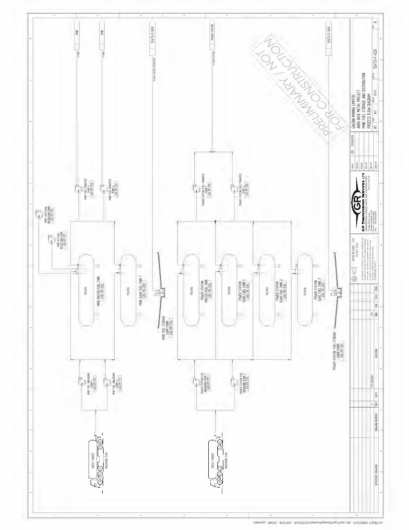
ENG
INEE
RIN
G C
ON
SULT
ANTS
AN
D C
ON
TRAC
TOR
S71
Dal
y St
reet
, Asc
otW
este
rn A
ustra
lia. 6
104
Phon
e: (0
8) 6
272
6000
Fax:
(08)
627
2 60
01
ACN
121
542
738
PREL
IMIN
ARY
/ N
OT
FOR
CO
NST
RUC
TION
I I I I A A A A A
-
~ ~ ~
~ -
~ ~
-
- ~
t> -
-
- -
C
~
~
LJ LJ LJ LJ
.. ~ ..
u ~ .. I a:::
LJ
C>i .. z ii z
~ ..
~
a:
"
LJ
• - L__; -- =1 1
-- b 1 - r==1 =t
- =1 1 - =1 :jl =1 ~
,=-:( - -- w
~ ~ ~ ~ ~ ~~ ~
~3 - -
=1 =1 =1 =1 =1 =1
~ . ~ ~
~
" LJ " LJ LJ LJ ~
- ~ : : -r ~ ,--- l(ci' ~
0 ,2,
l ~ 'a
- ~ >< -'-' ~ ~
J ~
I I I I

Works Approval Application: Supporting Information
Revision
Appendix E. Attachment 6B
JACOB:

Land & Marine Geological Services Pty Ltd(L&MGSPL)ABN 15 009 320 870
PO Box 777COWARAMUP WA 6284AUSTRALIAMobile +61(0)417 932 872
Reference: Galena Let 20181028.docm 29 October, 2018 | Page 1
29 October, 2018
Galena Mining LimitedSuite 5, 245 Churchill AvenueSUBIACO WA 6008 by email: [email protected]
Dear Troy
RE: THIRD PARTY GEOTECHNICAL REVIEW OF ABRA BASE METALS PROJECTTAILINGS STORAGE FACILITY DESIGN
With reference to the Third (3rd) Party Geotechnical Review of the design for the Tailings Storage Facility (TSF)for the Abra Base Metals Project, approximately 200 km north of Meekatharra, Western Australia, pleasefind attached the signed ‘Declaration by 3rd party independent technical reviewer tailings storage facilitydesign report’.
The following activities have been completed over the period from 23 August 2018 to 26 October 2018 aspart of this review of the proposed TSF for the Abra Base Metals Project:
i) Liaison with Galena Mining Limited (the project owner) and CMW Geosciences Pty Ltd (TSF designers)during the development of the design over the period from 23 August 2018 to 26 October 2018.
ii) A site visit, on 13 September 2018, to visually assess the site for the proposed TSF and view thepotential construction materials.
iii) Review of the Design Report by CMWGeosciences Pty Ltd, dated 24 October 2018, reference PER20180128AE Rev 1, including the appendices to the Design Report.
We trust this document meets your requirements and thank you for the opportunity to be part of this work.
Yours faithfullypp L&MGSPL
Christopher LanePRINCIPAL
Attachments ‘Declaration by 3rd party independent technical reviewer tailings storage facility design report’

DECLARATION BY 3RD PARTY INDEPENDENT TECHNICAL REVIEWER
TAILINGS STORAGE FACILITY DESIGN REPORT
Reference: Galena Let 20181028.docm 29 October, 2018 | Page 1
For and on behalf of Land & Marine Geological Services Pty Ltd, I, James Christopher Lane, being a qualifiedengineering/environmental geologist with over 33 years relevant experience in the field of tailingsmanagement, to verify tailings storage facility design and holding professional registration through thefollowing organisations:
Chartered Fellow of the Geological Society London, Registration No: 14006.
Registered Professional Geoscientist, The Australian Institute of Geoscientists, Registration No: 10009.
Chartered Member of the Australasian Institute of Mining and Metallurgy, Member No: 109219.
Registered Professional Engineer Queensland Geotechnical (Mining), Registration No: 14006.
and being independent of the applicant, do hereby declare and confirm that I have reviewed the Design Reportfor Tailings Storage Facility, Abra Gold Project, approximately 200 km north of Meekatharra, WesternAustralia, dated 24 October 2018, reference PER2018 0128AE Rev 1 prepared by CMW Geosciences Pty Ltd.
I do hereby confirm that the Design Report has been reviewed for compliance with the Department of Mines,Industry, Regulation and Safety (DMIRS), formerly the Department of Mines and Petroleum (DMP) documenttitled ‘Guide to the preparation of a design for tailings storage facilities (TSFs)’. The information contained inthe Design Report meets the design, operation and closure objectives stipulated in the Department of Mines,Industry, Regulation and Safety (DMIRS), formerly the Department of Mines and Petroleum document titled‘Code of Practice tailings storage facilities in Western Australia’.
I acknowledge that:
The Department of Mines, Industry, Regulation and Safety (DMIRS), formerly the Department of Mines andPetroleum, may rely on this declaration; and
That the provisions of the Design, Construction Specifications and Operating Manuals for the Abra TSF (TSFDesign Documents) must be strictly adhered to by the Owner and the storage must be constructed,operated, closed and rehabilitated strictly in accordance with the provisions of the TSF Design Documents.Land & Marine Geological Services Pty Ltd shall not be liable in any respect whatsoever for any damage toor failure in the operations of TSF resulting from failure of the Owner, its servants or agents to comply withthe provisions of the TSF Design Documents.
Signature of above person: Date 29 October, 2018.
CORPORATE ENDORSEMENT
I hereby confirm my opinion that the above mentioned 3rd Party independent technical reviewer is suitablyqualified with relevant experience and competence in tailings design and management and verify that thereviewer is truly independent of the applicant.
Name of Company (applicant): ………………………………………………………………………………………………………………………..
Signature of Company (applicant): Date……………………….

Unit 19 Wembley Green Offices,127 Herdsman Parade, Wembley, WA 6014 www.cmwgeosciences.com
24 October 2018
TAILINGS STORAGE FACILITY
ABRA BASE METALS PROJECT,NEAR MEEKATHARRA, WA
DESIGN REPORT
Galena Mining Limited Ref. PER2018-0128AE Rev 1
CMWGeosciences

Abra Base Metals Project, TSF Design Report 24 October 2018
CMW Geosciences Pty Ltd iRef. PER2018-0128AE Rev 1Design Report
Table of Contents1 INTRODUCTION ....................................................................................................... 1
1.1 Location................................................................................................................................. 2 1.2 Ownership ............................................................................................................................. 2 1.3 History ................................................................................................................................... 2
2 DESIGN CONSIDERATIONS ....................................................................................... 3
2.1 Process Type ........................................................................................................................ 3 2.2 Rated Throughput ................................................................................................................. 3 2.3 Ore Type ............................................................................................................................... 3 2.4 Tailings Properties ................................................................................................................ 3
2.4.1 Geochemistry ............................................................................................................................... 3 2.4.2 Residual Water Quality ................................................................................................................ 3 2.4.3 Engineering Properties ................................................................................................................ 4
2.5 Geotechnical Investigations .................................................................................................. 6
3 TAILINGS STORAGE FACILITY DESIGN ....................................................................... 7
3.1 Hazard Rating ....................................................................................................................... 7 3.2 Operation and Design Considerations .................................................................................. 7 3.3 Drawings ............................................................................................................................... 8 3.4 TSF Storage Characteristics................................................................................................. 8 3.5 Embankment Design............................................................................................................. 9 3.6 Embankment Geometry ........................................................................................................ 9 3.7 Water Recovery System ....................................................................................................... 9 3.8 Liners..................................................................................................................................... 9 3.9 Construction Methods ......................................................................................................... 10
4 SEEPAGE ANALYSIS ................................................................................................ 11
4.1 Model Assumptions............................................................................................................. 11 4.2 Results of Analyses............................................................................................................. 11
5 STABILITY ANALYSIS .............................................................................................. 12
5.1 Method of Analysis.............................................................................................................. 12 5.2 Parameters.......................................................................................................................... 12 5.3 Results of the Stability Analyses......................................................................................... 12 5.4 General Comments in Respect to Stability ......................................................................... 13
6 DEFORMATION ANALYSIS ...................................................................................... 13
7 SURFACE WATER DIVERSION ................................................................................. 13
8 FREEBOARD ........................................................................................................... 14
9 WATER BALANCE ANALYSES .................................................................................. 14
10 DAM BREAK ASSESSMENT ..................................................................................... 15
10.1 Breach Characteristics ........................................................................................................ 15 10.2 Energy Methods .................................................................................................................. 16 10.3 Hydraulic Modelling............................................................................................................. 17 10.4 Controls ............................................................................................................................... 17
11 OPERATIONAL ASPECTS ......................................................................................... 17

Abra Base Metals Project, TSF Design Report 24 October 2018
CMW Geosciences Pty Ltd iRef. PER2018-0128AE Rev 1Design Report
11.1 Operating Procedures ......................................................................................................... 17 11.2 Dust Management............................................................................................................... 18 11.3 Instrumentation and Monitoring .......................................................................................... 18 11.4 Emergency Action Plan....................................................................................................... 18
12 CLOSURE CONSIDERATIONS ................................................................................... 19
13 REFERENCES .......................................................................................................... 20
TablesTable 1 – Summary of Encountered Soil Stratigraphy
Table 2 – Summary of Falling Head Permeability Tests
Table 3 – Summary of Civil Engineering Laboratory Test Results
Table 4 – Drawings
Table 5 – Estimated Tailings Storage Areas and Storage Volumes
Table 6 – Permeability Values Adopted
Table 7 – Seepage Analyses Cases
Table 8 – Results of Seepage Analyses
Table 9 – Summary of Strength Parameters
Table 10 – Results of Stability Analyses
Table 11 - % Volume Release vs Pond size
FiguresFigure 1 –Site Plan
Figure 2 – Storage Capacity Curve
Figure 3 – Tailings Storage Data Sheet (TSDS)
Figure 4 – Explanatory Notes for completing TSDS
Figure 5 – Rainfall Intensity Chart
Figure 6 – Freeboard Nomenclature
AppendicesAppendix A – Drawings.
Appendix B – Geotechnical Investigation Report
Appendix C – Schedules of Quantities and Cost Estimates.
Appendix D – Seepage Analysis.
Appendix E – Stability Analysis.
Appendix F – Water Balance Analysis.
Appendix G – Laboratory Test Results – Tailings Test work.
Appendix H – Operations Manual

Unit 19 Wembley Green Offices,127 Herdsman Parade, Wembley, WA 6014 www.cmwgeosciences.com
EXECUTIVE SUMMARYGalena Mining Limited (GML) proposes to develop the Abra Base Metals Project located approximately 200 km north of Meekatharra, Western Australia. As part of the project, GML proposes to construct a TSF in order to store tailings from the process plant. The project is a greenfields development. The project comprises the development of a box cut for an underground mining operation, processing plant, TSF, airstrip and associated infrastructure.
The Abra Project is located within the granted mining licence M52/776. The TSF is located approximately 500m north of the proposed plant site, with an approximate centre at (MGA, Zone 50)coordinates 7,275,560 m North and 660,940 m East.
The TSF has been designed to store 8.48 Mt of tailings over a 15 year life. Approximately 32.6% of the total tailings production will be used for paste backfill to the underground mining operations. The tailings have unusual characteristics when compared with other mine tailings. Air drying and settling tests, drained and undrained, indicate that the tailings will settle out of suspension very quickly, in less than 80 minutes, which is a function of the high soil particle density. The TSF will be a two cell, paddock type facility, located to the north of the plant site, between two intermittent creek lines in order to reduce diversion works. The two cell TSF will be constructed in six stages. The Stage 1 Cell A starter embankment will provide nominally 2 year’s storage. Cell B will be added to provide an addition storage life of 2 years for Stage 1. The TSF starter embankments will be a zone embankment comprising an upstream zone of compacted select mine waste and a downstream zone of traffic compacted mine waste. The starter embankments will be raised using upstream construction techniques and select mine waste.
The design as incorporates a rock-ring decant in each cell to recover water from the TSF. Return water will be pumped directly to the process plant for reuse.
The starter embankments and TSF cell basins will be lined with Geosynethic clay liner (GCL) to produce a low permeability liner at the base of the TSF to reduce seepage.
A surface water diversion channels will be constructed as part of the development of the TSF site. This diversion channels and bunds will divert catchment runoff from the ridge areas, to the south of the TSF behind the plant site towards the north, away from the TSF.
Details of the design are presented on the drawings in Appendix A.
Classification of the TSF, at its ultimate height, in accordance with Tables 1 and 2 of the DMP (2013) code results in a hazard rating of ‘Category 1 – High’. The ANCOLD (2012) consequence rating is ‘Significant’ (refer Tables 1 and 2 of ANCOLD (2012)).
Seepage, stability, deformation and water balance analyses, and a dam break assessment were performed as part of the development of the design.
The proposed TSF has been designed such that a 1% AEP, 72-hour duration storm event can be temporarily stored on top of the facility plus a minimum of 0.5 m total freeboard. The design, however, assumes correct operational controls are adhered to and that water is continually removed from the facility, such that adequate freeboard is maintained.
The probability of major embankment failure of the TSF is assessed as being very low provided the TSF is implemented (constructed and operated) within the intent of the design in accordance with the scope of works for the construction and operations manual.
CMWGeosciences

Abra Base Metals Project, TSF Design Report 24 October 2018
CMW Geosciences Pty Ltd iRef. PER2018-0128AE Rev 1Design Report
GML, as operator of the project, makes the following commitments:
The TSF construction will be undertaken in accordance with the specifications and drawings. Construction will be supervised and monitored by personnel with experience in this type of construction. Details of construction will be provided in a construction report.
Prior to construction of the TSF, seal all investigation and exploration boreholes within the TSF footprint.
The TSF will be managed and operated in general accordance with an Operations Manual (to be compiled). Independent audits will be performed annually.
A minimum of twelve piezometers be installed in the foundations of the TSF cells as recommendedin the design. Water levels as a minimum will be read monthly, data plotted monthly and trends assessed. The results should be reviewed as part of the yearly audits.
The groundwater monitoring programme will be instituted for the TSF and will be integrated with the site environmental monitoring programme. Water levels will be read monthly and samples obtained quarterly. The results will be summarised in the site AER.
The closure plan for the Abra Project will include the TSF.
This summary of the TSF design will be distributed by the mine to the local Shire Council and to the relevant local pastoralists.

Abra Base Metals Project, TSF Design Report 24 October 2018
CMW Geosciences Pty Ltd 1Ref. PER2018-0128AE Rev 1Design Report
1 INTRODUCTIONThis document presents design details required by the Department of Mines, Industry, Regulationand Safety (DMIRS), formerly the Department of Mines and Petroleum (DMP), Western Australia, forthe Tailings Storage Facility (TSF) at the Abra Base Metals Project (Abra). The project is located approximately 200 km north of Meekatharra, Western Australia.
The project is a greenfields development. The project comprises the development of a box cut for an underground mining operation, processing plant, TSF, airstrip and associated infrastructure. A site plan showing the location of the Tailings Storage Facility (TSF) in relation to other proposedinfrastructure is presented as Figure 1.
The TSF has been designed to store 8.48 Mt of tailings over a 15 year life. The TSF will be a two cell, paddock type facility, located to the north of the plant site, between two intermittent creek lines in order to reduce diversion works. The two cell TSF will be constructed in six stages. The Stage 1 Cell A starter embankment will provide nominally 2 year’s storage. Cell B will be added to provide an addition storage life of 2 years for Stage 1. The TSF starter embankments will be a zone embankment comprising an upstream zone of compacted select mine waste (i.e. raise bore fines supplemented with borrow as required) and a downstream zone of traffic compacted mine waste from the underground development. The starter embankments will be raised using upstream construction techniques and select mine waste (i.e. mine development waste supplemented with borrow as required).
The starter embankments and TSF cell basins will be lined with a Geosynethic Clay Liner (GCL). The design as incorporates a rock-ring decant in each cell to recover water from the TSF. Return water will be pumped directly to the process plant for reuse.
Design contained in this report were prepared to meet DMIRS requirements and in accordance with the relevant guidelines as detailed below:
Department of Mines and Petroleum (2013), ‘Code of practice: tailings storage facilities in Western Australia’.
Department of Mines and Petroleum (2015), ‘Guide to the preparation of a design report for tailings storage facilities (TSFs)’.
ANCOLD Guidelines (2012) ‘Guidelines on Tailings Dams – Planning, Design, Construction, Operation and Closure’
Classification of the TSF, at its ultimate height, in accordance with Tables 1 and 2 of the DMP (2013) code results in a hazard rating of ‘Category 1 – High’ (Section 3.1). The design presented in this report has been undertaken using the hazard rating of ‘High’, based on the following:
Loss of life is unlikely.
Loss of TSF storage.
Damage to natural environment possible (impact area<5km2).
Prolonged adverse effects on flora and fauna possible.
Category 1 storage as final embankment height is 15 m.
A dam break assessment has been performed and the hazard rating is based on this assessment (refer to Section 10). A tailings storage data sheet and explanatory notes for the facility are presented as Figures 3 and 4 respectively.

Abra Base Metals Project, TSF Design Report 24 October 2018
CMW Geosciences Pty Ltd 2Ref. PER2018-0128AE Rev 1Design Report
The following figures and appendices complete this report:
Figure 1 –Site Plan.
Figure 2 – Storage Capacity Curve.
Figure 3 – Tailings Storage Data Sheet (TSDS).
Figure 4 – Explanatory Notes for completing TSDS.
Figure 5 – Rainfall Intensity Chart.
Figure 6 – Freeboard Nomenclature.
Appendix A – Drawings.
Appendix B – Geotechnical Investigation Report
Appendix C – Technical Specification and Schedules of Quantities
Appendix D – Seepage Analysis.
Appendix E – Stability Analysis.
Appendix F – Water Balance Analysis.
Appendix G – Laboratory Test Results – Tailings Testwork.
Appendix H – Operations Manual
1.1 Location
The Abra Project is located within the granted mining licence M52/776. The TSF is located approximately 500m north immediately south of the proposed plant site, with an approximate centre at (MGA, Zone 50) coordinates 7,275,560 m North and 660,940 m East. A layout plan showing the location of the TSF in relation to other mine infrastructure is presented as Figure 1.
1.2 Ownership
The project is owned and operated by publicly listed company, GML.
1.3 History
Abra is a globally significant lead-silver project located in the Gascoyne region of Western Australia. The deposit was discovered in 1981 and has been the subject of historical and modern exploration, and preliminary (scoping-level) economic studies. There has been no previous mining activity at Abra and the deposit does not outcrop, that is have a presence at the ground surface.
Galena undertook a PFS in 2017, to confirm the technical and economic robustness of developing an integrated mining and processing operation to produce a high-value, high-grade lead-silver concentrate at Abra.

Abra Base Metals Project, TSF Design Report 24 October 2018
CMW Geosciences Pty Ltd 3Ref. PER2018-0128AE Rev 1Design Report
2 DESIGN CONSIDERATIONSThe design for the TSF is based on the following:
Annual tailings production approx. 1.1 Mtpa of which 0.60 Mtpa will be permanently stored in the TSF.
Tailings slurry of 65% solids.
Life of Mine around 15 years.
Design in general accordance with ANCOLD Guidelines (2012). The consequence category will determine the water management (e.g. freeboard and stormwater storage capacity required) and geotechnical embankment design requirements.
The tailings for the paste fill will be taken direct form the processing plant, as and when needed and sent direct to the paste plant, with the balance of tailings not required being sent to the TSF. The TSF may at various times receive all the tailings stream, or when the paste plant is operational a reduced tailings stream or at times no tailings stream.
2.1 Process Type
Ore will be processed using flotation methods.
2.2 Rated Throughput
GML proposes a production rate of 1.1 Mtpa to 1.2 Mtpa
2.3 Ore Type
The ore comprises fresh ore from underground operations.
2.4 Tailings Properties
2.4.1 Geochemistry
Geochemical testing of the tailings has been executed by Graeme Campbell & Associates Pty Ltd and the tailings are classified as NAF and appreciably enriched in barite (Ba) which comprised almost 1/3 of the total tailings. The tailings are also enriched in lead (Pb) chiefly associated with ‘trace galena’ not recovered during flotation.
2.4.2 Residual Water Quality
Based on geochemical testing, the tailings water is likely to have the following properties:
pH of 7-8
Low salinity: electrical conductivity (EC) value of 430 μS/cm.
The concentrations of a wide range of minor-element in the tailings-slurry-water sample were either below, or close to, the respective detection-limits (0.000-0.01 mg/L).
The concentration of Pb of 0.068 mg/L is below the stock drinking water of 0.1 mg/L in the ANZECC (2000) Guideline. The guideline does not list a Ba guideline value for stock drinking water.

Abra Base Metals Project, TSF Design Report 24 October 2018
CMW Geosciences Pty Ltd 4Ref. PER2018-0128AE Rev 1Design Report
2.4.3 Engineering Properties
A representative tailings sample was testing as part of the PFS study. The tailings are a non-plastic sandy Silt (ML). The engineering properties of the tailings are summarised below.
Tailings Slurry
Slurry density ex-plant: approx. 65% solids
Tailings density: 1.997 t/m3 – Drained settling test
1.865 t/m3 (dry) – Undrained settling test
Assumed design density 1.865 t/m3
Specific gravity: 3.52
Angle of internal friction: 31º (assumed based on shear box testing)
Particle size distribution: 60% passing 75 , with approx. 3% passing 3
Hydraulic conductivity: 1.0 x 10⁻⁵m/s to 1.0 x 10⁻⁷-m/s
Tailings beach slope: 1% assumed
The above is compiled based on tailings testwork (refer Appendix G).
2.4.3.1 Comments on Tailings Testwork
The following commentary is provided for the tailings, based on the soil classification approach detailed in AS1726:2017 Geotechnical site investigations.
The results of the PSD and Atterberg Limits testing indicate that the tailings can be classified as a non-plastic sandy silt Unified Soil Classification (USC) group symbol ML.
The soil particle density of the tailings is 3.52 t/m3.
The Emerson Class Number Test indicates that the materials are dispersive.
The maximum dry density of the tailings, when compacted using the standard method of compaction, is 2.49 t/m3 with an optimum moisture content of 7.8%. The compaction curve is relatively flat.
The direct shear tests indicate a cohesion of 12.9 kPa and shear angle internal friction of 31.3o.
The air drying and settling tests, drained and undrained, indicate that the tailings will settle out of suspension very quickly, in less than 80 minutes, which is a function of the high soil particle density. The objective of the drained and undrained settling test is to monitor the tailings settlement and the development of clear supernatant water. By monitoring the height of the solids and the achieved drydensity over time, an indication of the speed at which this water is released can be assessed. The points to note from the results of the undrained settling test, undertaken on tailings slurry with a slurry density of 61.7% solids, are:
At discharge, the tailings slurry has an equivalent dry density of nominally 1.19 t/m3 and 1.09 t/m3 for the drained and undrained settling tests, respectively.
After a period of 260 minutes, the dry density increases to nominally 1.997 t/m3 for the drained test, whereas the undrained test reaches a dry density of 1.865 t/m3 after 107 minutes. The shape of the curves in both tests suggest significant water release can be expected within the first 4 hours following tailings deposition.

Abra Base Metals Project, TSF Design Report 24 October 2018
CMW Geosciences Pty Ltd 5Ref. PER2018-0128AE Rev 1Design Report
The airdrying test indicates water is available to decant within hours of deposition.
Under field conditions it is likely that supernatant water recovery would be approximately 56% not including any contribution from rainfall. This assumes a slurry density of 65% solids at the point of discharge.
The oedometer testing (consolidation testing) indicates a slow consolidation rate which will result in an increase in the in-situ dry density of the tailings stack with time. However, with the rapid settling on initial deposition, the increase in dry density is not going to make a substantial difference to the consolidation and settlement of the tailings, given the relatively low total height of the tailings profile.
2.4.3.2 Implications for Tailings Management
The implications for the TSF design and operation from a geotechnical perspective are:
The TSF design must provide sufficient tailings storage capacity in a timely manner for the tailings deposition. Whilst there is a significant percentage of the tailings, approximately 32.6%, being used for paste backfill to the underground mining operations, there is still a need for the remainder of the tailings to be stored.
A GCL liner to the base of the TSF is recommended. Drainage on top of the liner to pump out leachate from the stored tailings would not be required, given the rapid settling characteristics of the tailings. An efficient high capacity supernatant water recovery system (pumps and pipes) is essential, refer to Section 5.3, which provides details of the target insitu dry density and water recovery.
The high soil particle density and rapid settling characteristics mean that the tailings will be difficult to remobilise once they settle. In other words, release from the containment facility is not likely to result in significant runout and this has implication for the Dam Break Study.
The dispersive properties of the tailings demonstrate that the tailings will not be suitable for use in perimeter embankment construction for embankment raising works as traditionally is used for mining operations. Borrow materials will need to be sourced and tested to demonstrate embankment raising works can be executed for upstream embankment raising.
The supernatant water, which is readily released from the tailings slurry within very short time frames, must be recovered and utilised in the process plant. The water recovery system, pumps, pipes and process water storage dam, must be designed to accommodate a very high level of water recovery. It can reasonably be expected that a minimum of approximately 56% of the slurry water will be available for water recovery.

Abra Base Metals Project, TSF Design Report 24 October 2018
CMW Geosciences Pty Ltd 6Ref. PER2018-0128AE Rev 1Design Report
2.5 Geotechnical InvestigationsCMW/L&MGSPL conducted site reconnaissance’s of the Abra Project area in two mobilisations. Field investigations were carried out by GML explorations geologists under the direction of CMW/L&MGSPL and included.
Preliminary investigations included the drilling of air-core boreholes on a 200 x 200m grid pattern across the site. A total of 105 boreholes were drilled to a maximum depth of 20m.
Sampling of air-core samples as directed by CMW/L&MGSPL in order characterise materials.
Testpitting of a potential borrow area in the south west of the project area under the supervision of GML geologists.
Testpitting of the selected TSF site to the north of the plant under the supervision of GML geologists.
At the proposed borrow area (air-core bore locations APFS075, and APFS076) the Wiluna Hardpan was absent. The ground conditions were noted to be basically saprolite with some silicification near the surface. Testpitting in the proposed borrow area indicated shallow refusal on cemented materials at a depth of 1m or less. If this area was to be developed as a borrow area paddock blasting (long with material handling and compaction) would be required in order to generate materials suitable for embankment construction including fines within the borrow material.
At the proposed TSF site (Bore locations APFS056, and APFS029) air-core drilling indicated thick Wiluna Hardpan was observed overly saprolite at depth (>5 m). It was observed that the hardpan sample fines lacked plasticity.
The testpitting at the proposed TSF site indicated ground conditions comprising:
Colluvium overlying
Wiluna Hardpan
Depth to refusal averaged 0.5 m with a maximum depth to refusal of 1.45 m
The results of the laboratory testing on submitted air-core samples, indicated the following:
The results of the plasticity testing on samples from the proposed borrow area (depth 2-4m), indicated the fines were a non-plastic silty material to a low plasticity (CL) clayey material.
The results of the materials classification tests on the hardpan materials from the TSF area (depth 2-4m) indicated these materials were non-plastic silty gravel (GM) with a fines content (passing 75 micron) between 14% and 23%.
This testing confirms that a GCL will be required to line the TSF to manage seepage and that the TSF site is not a source of clayey materials.
A CMW geotechnical report summarising the investigations in more detail and presenting field and laboratory data is provided in Appendix B.

Abra Base Metals Project, TSF Design Report 24 October 2018
CMW Geosciences Pty Ltd 7Ref. PER2018-0128AE Rev 1Design Report
3 TAILINGS STORAGE FACILITY DESIGN The design objectives of the TSF at Abra are:
Providing optimum removal of water from the facility for return to the process plant for re-use.
Optimising tailings storage capacity by maximising the in-situ tailings density (i.e. undertaking cyclic tailings deposition between groups of spigots).
Reducing environmental impact (i.e. due to seepage).
Drawings PER2018-0128-01 to PER2018-0128-03 provide the general arrangements, and sections and details for the TSF design (refer Appendix A). Preliminary specifications for earthworks are provided in Appendix C. Schedules of quantities for the staged construction of the TSF are also included in Appendix C.
3.1 Hazard RatingBased on the DMP Code of Practice (2013), the hazard rating for the TSF has been assessed as ‘High’, Category 1 based on the following:
Loss of life is unlikely.
Loss of TSF storage.
Damage to natural environment possible (impact area<5 km2).
Prolonged adverse effects on flora and fauna possible.
Category 1 storage as final embankment height is 15m.
The ANCOLD (2012) consequence rating based on the above considerations, that is overall Majordamage, (refer Table 1 of ANCOLD (2012)) and a population at risk of <1 is ‘Significant’ (refer Table 2of ANCOLD (2012)). Major damage is characterised potential significant effects on river systems of local and state significance. Other impacts have been assessed as medium, that is, potential significant impacts to business (i.e. the mine), impact area <5 km2 or less and impact duration less than 5 years. The loss of infrastructure is expected to be less than $10M (i.e. a minor damage type).
3.2 Operation and Design Considerations
The following operational considerations have been incorporated into the design:
Tailings in the form of slurry will be discharged sub-aerially and cyclically into the facility in thin discrete layers, not exceeding 300mm thickness, in order to allow optimum density and strength gain by subjecting each layer to a drying cycle. Deposition will take place via multiple spigots from around each cell of the facility.
The tailings have rapid settling characteristics, hence some experimentation will be required on the number spigots to be utilised during deposition. If too many spigots are open, the tailings will tend to deposit near the embankment. If this occurs, single point discharge practices may be required from time to time to force the tailings away from the embankment.
Spigotting of tailings is to be carried out such that a beach is developed to force the supernatant pond to be is maintained within and around the rock-ring decant. The pond is to be maintained away from the perimeter embankments at all times.

Abra Base Metals Project, TSF Design Report 24 October 2018
CMW Geosciences Pty Ltd 8Ref. PER2018-0128AE Rev 1Design Report
Water will be removed from the facility and pumped back to the process plant via a decant pumplocated in a rock-ring decant structure. The recommended average water recovery should not be less than 50% of slurry water inflow or 36 t/hr.
The tailings storage area will assume the form of a truncated prism with a depressed cone on thetop surface. The facility will have the capacity to store a considerable volume of water during a storm event. The minimum operational freeboard for the TSF under normal operating conditions is 0.5m, plus allowance for temporary storage of the 1% average exceedance probability (AEP) 72-hour storm event whilst maintaining required total freeboard (Section 8).
On eventual decommissioning, the facility will remain as a permanent feature of the landscape and drain to an increasingly stable mass. The top surface and batters will be stabilised and rehabilitated as described in Section 12.
3.3 Drawings
The following design drawings are presented in Appendix A.
Table 4: DrawingsTitle Drawing No.General Arrangement – Stage 1 PER2018-0128-01General Arrangement – Final Stage PER2018-0128-02Sections and Details PER2018-0128-03Instrumentation Arrangement and Details PER2018-0128-04
3.4 TSF Storage Characteristics
The estimated tailings storage areas, volumes and storage capacity for the TSF are summarised inTable 5 based on a minimum of approximately 32.6%, being used for paste backfill to the underground mining operations. The estimated storage characteristics of the proposed TSF assume tailings insitu densities and beach slopes as quoted in Section 2.
Table 5 - Estimated Tailings Storage Areas and Storage Volumes
StageCrest RL
(m)Area(ha)
Storage Volume
(m3)
Cumulative Total Tailings
Production (Mt)
Cumulative Tailings Stored
in TSF (Mt)
Cumulative Storage Life
(years)
1 – Cell A 539.5 26.5 800,000 2.1 1.49 2.6
1 – Cell B 535.5 37.5 800,000 4.4 2.98 5.3
2 – Cell A 542.5 24.5 764,713 6.5 4.41 7.8
2 – Cell B 538.5 35.1 1,088,858 9.5 6.44 11.4
3 – Cell A 545.5 22.5 822,896 11.0 7.54 13.3
3 – Cell B 541.5 32.8 1,187,402 13.8 9.43 16.7
Note: Storage life based on design criteria in Section 2.4.3 and an average tailings production of 0.565 Mtpa. Total tailings to TSF based on an average production 0.83 Mtpa.

Abra Base Metals Project, TSF Design Report 24 October 2018
CMW Geosciences Pty Ltd 9Ref. PER2018-0128AE Rev 1Design Report
3.5 Embankment DesignThe TSF has been designed to store 8.48 Mt of tailings over a 15 year life. The TSF will be a two cell, paddock type facility, located to the north of the plant site, between two intermittent creek lines in order to reduce diversion works. The two cell TSF will be constructed in six stages.
The Stage 1 Cell A starter embankment, with a maximum height of 9 m, will provide nominally 2 year’s storage with a tailings impoundment area of approximately 26.5 ha. Cell B will be added to provide an addition storage life of 2 years for Stage 1. Cell B Stage 1 will have a maximum height of 8 m with a tailings impoundment area of approximately 37.5 ha.
The Stage 1 embankments will be raised by 3m in Stages 2 and 3 to provide the life of mine storage of 15 years.
The TSF starter embankments will be a zone embankment comprising an upstream zone of compacted select mine waste and a downstream zone of traffic compacted mine waste. The select mine waste will be sourced from raising bore fines or other approved mine waste sources. General mine waste from underground and the box cut will be stockpiled in a waste dump area, located near the TSF site.The starter embankments and TSF cell basins will be lined with GCL.
The starter embankments will be raised using upstream construction techniques. The staged raising embankment construction will utilise select mine waste material or from external borrow areas to be identified near the TSF site.
The final stage will have a tailings impoundment area of approximately 55 ha (both cells) with a maximum embankment height of 15 m.
3.6 Embankment Geometry
The TSF embankment will have design slopes of 1(V):2(H) upstream and 1(V):3(H) downstream.
The starter embankment and upstream raised embankments will have a minimum crest width of 6 m.The embankment crest will have a 2% cross-fall towards the upstream side and 0.5m (min.) high mine waste windrow at the downstream crest.
The decant causeway has design slopes of 1:1.5 (V: H) and a 6m minimum crest width. The crest of the decant causeway will have 0.5m (min.) windrows on both sides of the accessway. Breaks in the windrow on the low side will allow surface water to run off.
The design geometry of the proposed TSF Embankment construction is presented on Drawing PER2018-0128 -03 in Appendix A.
3.7 Water Recovery System
Surface water will be removed from TSF by a decant pump located within a rock-ring type decant located centrally within the TSF. Return water will be pumped directly to the process plant for reuse.
At start-up a temporary decant pump should not be required as the rock-ring is located such that earlywater return will be possible.
3.8 Liners
Due to the presence of Wiluna hardpan near the surface, which has been assessed as having medium to low permeability, it is proposed to line the TSF basin (Stage 1 only) with a GCL. The permeability of a GCL is around 10-12 m/s.

Abra Base Metals Project, TSF Design Report 24 October 2018
CMW Geosciences Pty Ltd 10Ref. PER2018-0128AE Rev 1Design Report
3.9 Construction MethodsThe starter embankment of the TSF will be a zoned embankment. The starter embankment will be raised in stages using upstream methods. The staging will comprise:
Stage 1, Cell A Starter: construction of the starter embankments to crest RL539.5 m anddrainage diversion. This construction will proceed utilising a civil earthworks contractor, prior to commissioning the plant.
Stage 1, Cell B Starter: construction of the starter embankments to crest RL535.5 m in Year 2.This construction will proceed utilising a civil earthworks contractor.
Stage 2: raising construction of embankment by 3 m:
Cell A: Raising of embankments in Year 4, likely by a civil contractor.
Cell B: Raising of embankments in Year 7, likely by a civil contractor.
Construction of the decant accessway and decant rock-ring either by the mining operation or a civil contractor.
Stage 3: raising construction of embankment by 3 m:
Cell A: Raising of embankments in Year 11, likely by a civil contractor.
Cell B: Raising of embankments in Year 13, likely by a civil contractor.
Raising of the decant accessway and decant rock-ring either by the mining operation or a civil contractor.
As part of Stage 1, the footprint of the TSF will be cleared of vegetation. The topsoil from the footprint of the TSF will be stripped and stockpiled for use in rehabilitation. The vegetation and topsoil will be stockpiled separately.
The embankments should be constructed to the following standards:
Starter and Upstream Raises
Construct the TSF starter embankment, upstream zone and upstream raises using select mine waste material sourced from the raise bore fines or other identified borrow sources.
TSF starter embankment, upstream zone shall be trimmed such the embankment batter is adequate for accepting the GCL liner (i.e. free of projects that could damage the liner).
The select mine waste should be moisture conditioned (2%, +2% of the optimum moisture content (OMC)).
Each 0.3m layer shall be compacted to achieve a density ratio greater than 95% of the maximum dry density - standard compaction.
Construct the downstream zone of the TSF starter embankment using general mine waste material sourced from the underground operations and stockpiled in a dump near the TSF. The downstream zone should be traffic compacted in 1 m layers using loaded construction equipment. The dump truck shall traffic the complete width of the zone.

Abra Base Metals Project, TSF Design Report 24 October 2018
CMW Geosciences Pty Ltd 11Ref. PER2018-0128AE Rev 1Design Report
4 SEEPAGE ANALYSISSeepage analyses were undertaken to estimate the position of the phreatic surface for the embankment design for the proposed starter embankment stage (embankment height 9 m) and final stage (15 m embankment height). The analyses were undertaken using the groundwater module of the Slide software package. Slide uses a 2D finite element analysis to determine groundwater seepage for saturated, steady state flow conditions. It should be noted that 2D modelling is a simplistic approach, which does not consider 3D effects.
4.1 Model AssumptionsThe upstream boundary condition used in the analyses was determined based on a maximum water pond level of 1.0 to 1.5 m below the embankment crest. The water pond was assumed to be no closer than 150 m from the embankment crest. Under normal operating conditions it is expected that the decant pond would be within the rock-ring decant (i.e. > 150m from the embankment).
The material permeabilities used in the seepage analyses are based on values taken from the recent geotechnical investigations and assumed text book values. Table 6 provides a summary of the permeability values used in the analyses.
Table 6 - Permeability Values Adopted
Material Zone Permeability, K (m/s) Comments on Assumptions
Deposited Tailings 10-6 Assumed value based on tailings testwork
Compacted Mine Waste 10-4 Assumed value based on materials specification and textbook values
Select Mine Waste 10-9 Assumed value for a combination of GCL over selected mine waste
Foundation Soils 10-9 # Assumed value for a combination of GCL over colluvium over hardpan
# GCL has a nominal permeability of 10-12 m/s, however 10-9 m/s has been adopted in the finite element analyses due to mathematical instability.
4.2 Results of AnalysesThe seepage flow determinations from the analyses are summarised in Table 7, below.
Table 7 - Results of Seepage Analyses
CaseSeepage Flow(m³/day/m of
embankment)
Approximate Embankment Length (m)
Estimated Seepage per day for
embankment section (m³/day)
Starter Embankment 0.00000036 1,500 <0.0005Final Embankment 0.0000031 1,500 <0.005
Plots of the phreatic surface and distribution of pore pressures throughout the embankment are presented in Appendix D for the two cases analysed.
The seepage analyses indicate very low seepage flow can be expected from the TSF. The use of a GCL in lining the facility will ensure negligible seepage from the TSF.

Abra Base Metals Project, TSF Design Report 24 October 2018
CMW Geosciences Pty Ltd 12Ref. PER2018-0128AE Rev 1Design Report
5 STABILITY ANALYSIS
5.1 Method of AnalysisStability analyses were undertaken to assess the stability of the TSF embankment for the proposed starter embankment stage (embankment height 9 m) and final stage (15 m embankment height). The analyses were undertaken in general accordance with ANCOLD (2012).
The computer software package ‘Slide’ was utilised to undertake the analyses. Slide is a two-dimensional slope stability program for evaluating the safety factor of circular and non-circular failure surfaces in soil and rock slopes. The stability of the slip surfaces for static loading was assessed using vertical slice limit equilibrium methods and the stability of the slip surfaces for seismic loading was assessed using finite element method. The simplified Bishop method was used in the static analyses.
The phreatic surface adopted in all cases were based on the seepage analyses results, refer to Section 4. Drained and undrained conditions were analysed.
ANCOLD (2012) requires deformation analysis and this is presented in Section 6. It should be noted that the TSF embankment foundations are not liquefiable and hence post-seismic analyses are not applicable.
5.2 ParametersTable 8 provides a summary of the strength parameters used in the stability analyses.
5.3 Results of the Stability AnalysesThe results of the stability analyses for the various cases examined assuming a ‘worst’ case phreatic surface are summarised in Table 9, with the computer printouts presented in Appendix E.
Table 9 - Results of Stability Analyses
Case Factor of Safety Recommended Minimum Factors of Safety*
Starter Embankment - Drained 2.50 1.5Starter Embankment - Undrained 2.50 1.5
Final Embankment - Drained 2.43 1.5Final Embankment - Undrained 2.43 1.5
The stability analyses indicate that the cases examined generally have adequate factors of safety for the drained and undrained conditions when compared with the recommended minimum factors of safety in ANCOLD (2012).
Table 8 - Summary of Strength Parameters*
Material Type Bulk Density(kN/m³)
Undrained Strength
Parameter Su (kPa)
Effective Strength Parameter*
Cohesionc/ (kPa)
Friction Angle/ (degrees)
Compacted Mine Waste 20 N/A 0 38Select Mine Waste 20 75 5 35Foundation Soils 21 N/A 200 38Tailings 22 50 0 31Rock Armour 22 N/A 0 40

Abra Base Metals Project, TSF Design Report 24 October 2018
CMW Geosciences Pty Ltd 13Ref. PER2018-0128AE Rev 1Design Report
5.4 General Comments in Respect to StabilityStability is significantly influenced by the position of the phreatic surface within the deposited tailings and confining embankment.
The tailings storage has been designed to provide temporary water storage following extreme storm events. If water does extend to the embankment, which is considered very unlikely, it is anticipated this will be a temporary occurrence given ‘continuous’ water removal from the TSF. The tailings storage should be operated in such a manner as to ensure that the `normal’ supernatant pond is kept well away from the embankment, within the rock-ring decant, at all times.
6 DEFORMATION ANALYSISA preliminary assessment of embankment deformation due to earthquake was estimated using aPlaxis 2D finite element analysis (FEA) and the in-built pseudo-static acceleration module. This method is conservative as it does not attempt to model the dynamic and short-term nature of most earthquakes. The displacements and settlements expected for a 15 m high embankment were estimated under a Magnitude 8 earthquake, corresponding with a loading of 0.104g for 1 in 1,000 AEP MDE or SEE event. The stiffness parameters used for each of the soils are provided in Table 10 below.
From the analysis, it is concluded that for the highest embankment section (worse case), the lateral deformation at the top of the embankment due to a SEE event is unlikely to exceed approximately20 mm, with approximately 4 mm of vertical displacement. Such deformation is insignificant when compared with the operational freeboard of 0.3 m.
7 SURFACE WATER DIVERSION
A surface water diversion channels will be constructed as part of the development of the TSF site. This diversion channels and bunds will divert catchment runoff from the ridge areas, to the south of the TSF behind the plant site towards the north, away from the TSF. Based on hydrology assessments by Rockwater, diversion channels have been designed on the following basis.
CMW have designed the diversion drains based on Rockwater peak flow rates and 1:100 yr. AEP flows. The peak flow assessments were based on the Rational method. The estimated peak flows for the catchments are summarised below along with the minimum channel requirements. The channel requirements assume a nominal channel slope of 1% and a Manning’s number of 0.025, further details are provided as footnotes to Table 5.
Table 10 - Summary of Stiffness Parameters
Material Type E’ (MPa) v
Compacted Mine Waste 80 0.2Select Mine Waste 100 0.2Foundation Soils 400 0.1Tailings 20 0.3Rock Armour 120 0.2

Abra Base Metals Project, TSF Design Report 24 October 2018
CMW Geosciences Pty Ltd 14Ref. PER2018-0128AE Rev 1Design Report
Table 5 - Estimated Tailings Storage Areas and Storage Volumes
CatchmentArea(km2)
Design Flow, Q100(m3/s)
Drain Width (invert) (m)
Drain Depth (m) Levee height (m)
Flow Depth (m)
D 0.74 24.8 8.0 0.5 1.0 0.8 approx.
E 1.17 34.0 8.0 0.5 1.0 1.0 approx.
Note: Catchment D is above the western side of the TSF, and Catchment E is above the eastern side of the TSF. All channel batter slopes will be 1:2 (v:h)
8 FREEBOARD
The following considerations were made regarding freeboard criteria and requirements for a ‘Medium’consequence category TSF (Section 3.1) based on the DMP (2013)2 guide:
The proposed TSF has been designed such that a 1% AEP, 72-hour duration storm event can be temporarily stored on top of the facility. The design, however, assumes correct operational controls are adhered to and that water is continually removed from the facility, such that minimum freeboard allowances are maintained.
Provision of a minimum of 500mm total freeboard comprising minimum operational freeboard (vertical height between the tailings beach and embankment crest) of 300mm and a minimum beach freeboard of 200mm plus and allowance for the 1% AEP 72 hour event of 217 mm.
ANCOLD guidelines (2012) also recommend an allowance for wave run-up for 1:10 AEP wind plus 0.3m additional freeboard for a ‘Significant’ consequence category TSF (refer to Section 3.1). It should be noted that, for the proposed perimeter tailings deposition, it is expected that the separation distance between the perimeter embankments and design storm pond will be adequate to prevent wave action on the embankments.
Intensity-frequency-duration (IFD) data pertaining to the site is presented on Figure 5. Freeboard nomenclature is illustrated on Figure 6. Temporary storage of a storm-water volume of approximately 82,250m3 (i.e. 37.9ha x 217 mm) on top of TSF resulting from a 1% AEP, 72-hour storm event was considered in the design. This storm-water volume will occupy approximately 20 to 25% of the TSF basin.
9 WATER BALANCE ANALYSES
A water balance analysis for the proposed TSF operation has been undertaken using a spreadsheet to examine expected TSF inflows and outflows.
Inflows and outflows for the facility were estimated on a monthly basis. Inflows include rainfall and slurry water. Outflows include evaporation, seepage losses and water retained in tailings (pore water). Water balance calculations are included in Appendix F.
Assumptions and other data adopted for the water balance are listed below:
Climate data was obtained from the BOM, utilising mean monthly rainfall and mean monthly evaporation figures for Tangadee Station (1960 to 2018) and Mt Clere (1975 to 2005).
Tailings area: half of the overall area of approx. 37 ha (the largest TSF cell)

Abra Base Metals Project, TSF Design Report 24 October 2018
CMW Geosciences Pty Ltd 15Ref. PER2018-0128AE Rev 1Design Report
Runoff coefficient of 0.4 for tailings was assumed.
Pool area and running beaches equal to 10,000m2.
Evaporation pan factor of 0.7.
Average retained moisture content of tailings, 25%.
Tailings slurry density of 65% (Section 2.4).
Tailings production rate of 600,000tpa.
Permeability for seepage through deposited tailings and GCL Lined TSF floor 10-10 m/s.
The results of the analysis indicate potential annual average water returns of around 50% to 55% of the tailings slurry water deposited into the facility can be expected under average climatic conditions.
The water recovery system, pumps and piping must be designed for a minimum recovery of not less than 1,317 m3/day. This will allow an average water return of 860 m3/day plus removal from the facility of stormwater from 1% AEP, 72-hour storm event over 180 days.
The results also indicate that water recovery will vary according to the management of the facility, specifically the size of the pond and running beaches. The actual quantity of water available for return to the plant may vary from the figures presented based on the following factors:
Variations in slurry density.
Continuity of tailings discharge.
Distance between the discharge point and decant pond.
Size of the decant pond and running beaches from where evaporation is greatest.
Climatic conditions at the time of operation.
The efficiency of the decant system during operation.
10 DAM BREAK ASSESSMENT
10.1 Breach CharacteristicsIf a TSF embankment breach were to occur, tailings would only be partially released from the storage impoundment, as the majority of the tailings beaches would have dried back, consolidated and gained. In addition, remobilised tailings will behave as a thickened slurry rather than lower viscosity water (refer below for addition comments in Section 10.2). It should be noted that if a dam break to occur tailings is not likely to affect the plant site and other infrastructure (i.e. portal etc) as these facilities are upslope of the TSF (by >7m).
Under worst case probable maximum precipitation (PMP) Rainy day failure conditions:
The storage capacity of TSF is estimated at 2.4 Mm³.
PMP storm volume is estimated at 311,000 m³. This was based on a PMP, 6 hour event, estimated using the generalised short duration method (GSDM), rainfall depth of 820 mm over the TSF catchment of 37.9 ha.
The tailings failure volume likely to be released from TSF at the final stage height of nominally 15 m, in the event of an embankment failure under PMP rainy day conditions, would be in the order of 956,000 m³, i.e. approximately 33% of the impounded storage capacity plus the PMP storm volume.

Abra Base Metals Project, TSF Design Report 24 October 2018
CMW Geosciences Pty Ltd 16Ref. PER2018-0128AE Rev 1Design Report
Based on T MacDonald and J Langridge - Monopolis (1984), embankment breaches typically occur relatively quickly (typically 0.5 an hour to 4 hours), however in the instance of an IWL with a wide embankment development of a breach will occur over a longer period of time. Based on this methodology, it is estimated that the breach will occur over 1 hour.
The Rourke and Luppnow Method (ref: H Rourke, D Luppnow, 2015) for estimating volume released from the TSF was also utilised to assess potential stored volume release. This method is based on a relation between the potential volume released from a TSF and the size of the decant pond. The greater the pond area the greater the potential volume released from the TSF. The following summarises the potential volume released from the TSF due to a dam-break for various pond sizes.
Table 10: % Volume Release vs Pond size (ref: H Rourke, D Luppnow, 2015)
Pond Area (ha) Pond Ratio (as a %) % of TSF volume release
Comments
1.5 4 4 Normal pond area i.e. adopted in water balance
18 48 33 % released based on recommendation in Dalpatram
(2011)
21 55 36 Pond area following PMP event
It was noted from Rourke and Luppnow analysis of past TSF failures, that the release volume varies between 9% and 67% of stored volume. The 33% of TSF volume or approximately 956,000 m3
scenario represents a likely maximum release from a paddock storage TSF with no externalcatchment in a semi-arid region of WA (i.e. the water pond should not be this large as the water balance is a negative water gain and water shouldn’t accumulate on the facility).
The Rourke and Luppnow Method demonstrates that in order to mitigate the consequence of a dam-break, the pond volume and area should be minimised by the adoption of good operating practices.
10.2 Energy MethodsUse of energy methods to estimate tailings run-out were considered for breach of the low embankment adjacent to the plant site. In these methods, the tailings and the embankment are assumed to liquefy and move as a block downstream.
The high soil particle density, rapid settling characteristics of the tailings and shear strength, means that the tailings will be difficult to remobilise once settled. In other words, release from the containment facility, in the event of a breach of the tailings embankment, will not result in significant runout.
Based on Sneddon 2010 method, assuming a 11m embankment height (near the Plant), a volume offailed material of 960,000m3 and an undrained shear strength of 7kPa, the estimated run-out distanceis 130m.

Abra Base Metals Project, TSF Design Report 24 October 2018
CMW Geosciences Pty Ltd 17Ref. PER2018-0128AE Rev 1Design Report
10.3 Hydraulic ModellingThe result from breach modelling indicates that the maximum run-out flow from a ‘dam break’ under ‘worst case’ (PMP) rainy day conditions will be 613 m3/s over 1 hour (assuming a triangular hydrograph).
In a worst-case scenario, tailings and water run-out will likely flow to the north along natural drainage lines away from the plant area and other infrastructure. It should be noted that the plant and portal to the south of the TSF cannot be affected by a TSF breach.
The main consequence of a dam break is likely to be:
Economic loss due to mine and plant shutdown and production loss, repairs of damaged sections of TSF.
Environmental impact: the potential for contamination of soils and surface water downstream of the TSF will be limited (estimated to be less than 5 km2).
Loss of human life: the loss of life of personnel is not likely. There is potential for loss of life of mining personnel visiting the TSF.
10.4 ControlsThe conditions for TSF embankment failure to occur would be driven largely by the size and extent of the decant pond on the facility as well as the magnitude of a trigger seismic event, embankment deformation, the grading of the tailings and saturation of the tailings adjacent to the embankment. Effective management of the decant pond to ensure excess water is continually removed and that the location of the pond is maintained within the rock-ring decant will minimise the risk of a main embankment breach and release of saturated tailings.
TSF embankment failure is not expected provided the facility is operated in accordance with the requirements set out in the TSF Operations Manual.
In the event that the TSF were in imminent danger of failure and breach, an Emergency Action Plan (EAP) would need to be enacted (see Section 11.4).
11 OPERATIONAL ASPECTS
11.1 Operating ProceduresA summary of the operations design for the TSF is presented in Section 3.2. An operations manual for TSF outlining the operating procedures, inspection criteria, monitoring requirements and log sheets for the facility should be compiled during the detailed design phase of the project development.
The following routine inspection and maintenance procedures are to be carried out for the various components of the system. A minimum of one inspection should to be undertaken during each shift by an operator or shift supervisor.
The inspections should cover:
the pipelines (tailings delivery line and water return lines) to and from the TSF.
leak detection.
pumps.
valves.
discharge locations.
location and size of the decant pond.

Abra Base Metals Project, TSF Design Report 24 October 2018
CMW Geosciences Pty Ltd 18Ref. PER2018-0128AE Rev 1Design Report
decant and return water pumps.
the general integrity of the embankments and GCL i.e. any new cracking (daily).
seepage downstream of the TSF.
any changes to existing cracking or seepage.
A monthly independent inspection should also be performed by senior site management. Operation, safety and environmental aspects should be periodically reviewed during an annual audit inspection by a suitably experienced and qualified engineer.
11.2 Dust Management
Provision for the TSF construction works will include a water cart on location to provide dust suppression as required. This control measure will prevent dust becoming airborne and subsequently being mobilised into the surrounding environment, from becoming a visibility issue, or from becoming a respiratory hazard for construction personnel.
During operations, the tailings beach will be kept damp in order to reduce the risk of dust generation during winding conditions.
11.3 Instrumentation and MonitoringGroundwater monitoring bores will be established around the TSF perimeter, as recommended by the project hydrogeologist.
Installation of 12 piezometers (6 locations x 2 piezometers per location) have been included in the design, to monitor any phreatic surface within the embankments and foundations. For details of the piezometers, refer to drawing PER2018-0128-04.
It is recommended that as a minimum:
Piezometer data will be collected as a minimum monthly using a data logger and the data download to a computer spreadsheet.
Groundwater level readings in the monitoring bores are to be taken monthly.
Groundwater samples from the monitoring bores for laboratory analyses will be taken quarterly.
Information collected from the monitoring bores and piezometers should be reviewed regularly and reported in an annual audit.
The requirement for additional instrumentation (i.e. monitoring bores, piezometers) associated with the TSF should be reviewed as part of the yearly audit.
11.4 Emergency Action PlanThe TSF Operations Manual provides a description of the operating procedures for the facility and includes an Emergency Action Plan. The Emergency Action Plan for the site should be updated based on the results of the dam break analyses presented in Section 10. The plan should be reviewedand updated as a minimum on a yearly basis.
The plan should include:
Management responsibilities and emergency coordination
Muster points
Seeking specialist geotechnical advice

Abra Base Metals Project, TSF Design Report 24 October 2018
CMW Geosciences Pty Ltd 19Ref. PER2018-0128AE Rev 1Design Report
Emergency Plan Triggers
Freeboard less than design values
Elevated piezometer levels
Significant embankment distress
Imminent overtopping
12 CLOSURE CONSIDERATIONSThe downstream slopes of the TSF perimeter embankments will be progressively rehabilitated by capping the batters with 0.5 m of mine waste to reduce erosion.
At decommissioning of the TSF, all pipework and pumps will be removed and access roads and other infrastructure rehabilitated.
Further rehabilitation of the downstream batter slopes of the TSF perimeter embankments will comprise deployment topsoil recovered from the site and cross ripping with a dozer. The maximum slope angle of the embankment batters will be 20o, with no intermediate benches.
Once tailings deposition has been completed within the TSF and the top surface of the tailings has gained adequate bearing capacity, it will be covered with nominally 1.5 to 2 m of NAF mine waste.This 1.5 to 2 m thick cover will act as a ‘store and release’ cover over the top surface of the TSF in order to reduce water ingress into the tailings profile.
At final closure, the decant structure will be decommissioned and the decant area ‘sealed’.
As the TSF is a two cell paddock facility with limited external catchments reporting to the TSF basin, a closure spillway should not be required at closure to cater for a probable maximum flood (PMF) event as the TSF basin on top of the finished tailings surface should have sufficient capacity to store a PMF event (provide the cover follows the final tailings profile).
A detailed closure study will need to be undertaken for the Abra Base Metals Project and this study will incorporate the TSF.

Abra Base Metals Project, TSF Design Report 24 October 2018
CMW Geosciences Pty Ltd 20Ref. PER2018-0128AE Rev 1Design Report
13 REFERENCES
The following standards and references were used in the preparation of this report.
1. Department of Mines and Petroleum (2013). ‘Code of Practice, Tailings Storage Facility in Western Australia’.
2. Department of Mines and Petroleum (2015). ‘Guide to the preparation of a design report for tailings storage facilities (TSFs)’.
3. ANCOLD (2012). ‘Guidelines on Tailings Dams Planning, Design, Construction, Operation and Closure’.
4. Land & Marine Geological Services Pty Ltd (2018), ‘Abra Base Metals Project, Tailings Storage Facility, Pre-Feasibility Study’, prepared for Galena Mining Limited
5. Rockwater (2018), ‘Abra Lead Silver Project, Hydrology and Surface – Water Assessment’,prepared for Galena Mining Limited
6. Australian Government Bureau of Meteorology website, http://www.bom.gov.au/.
7. AS 1170.4-2007. ‘Australian Standard Structural design actions Part 4: Earthquake actions in Australia’.
8. T MacDonald and J Langridge - Monopolis (1984). ‘Breaching Characteristics of Dam Failures’,Journal of Hydraulic Engineering, May 1984.
9. A Dalpatram (2011). ‘Estimation of Tailings Dam Break Discharges’, presentation at USSD workshop on Dam Break Analysis Applied to Tailings Dams.
10. H Rourke, D Luppnow, (2015), ‘The Risks of Excess Water on Tailings Facilities and its Application to Dam-Break Studies’, Tailings and Mine Waste Management for the 21st Century, Sydney NSW.
For and on behalf ofCMW Geosciences Pty Ltd
Christopher Hogg
Principal Tailings Engineer
Distribution: 1 copy to GML (electronic) Original copy held by CMW Geosciences Pty Ltd

Abra Base Metals Project, TSF Design Report 24 October 2018
CMW Geosciences Pty LtdRef. PER2018-0128AE Rev 1Design Report
Figures

CLI
ENT:
PRO
JEC
T:
TITL
E:
DR
AWN
:
SCAL
E:
PRO
JEC
T:
DAT
E:
REV
ISIO
N:
FIG
UR
E:C
HEC
KED
:
SHEE
T:
LAN
D &
MA
RIN
E G
EO
LOG
ICA
LS
ER
VIC
ES
PT
Y L
TD
GA
LEN
A A
BR
A T
SF
DE
SIG
N
GE
NE
RA
L A
RR
AN
GE
ME
NT
PLA
N(S
TA
RT
ER
EM
BA
NK
ME
NT
)
DE
PER
2018
-012
8
23.1
0.18
CL
01
11:
10,0
00
A3 L
020
030
040
050
0 m
100
1:10
000
TSF
CEL
L B
TSF
CEL
L A
ACC
ESS
RAM
P (1
IN 1
0)
DEC
ANT
RO
CK
RIN
GS
PLAN
T
CR
EST
RL5
39.5
m
CR
EST
RL5
35.5
m
1.BA
SE P
LAN
PR
OVI
DED
BY
CLI
ENT
NO
TES:
PRO
POSE
DBO
RR
OW
AREA
POR
TAL
SUM
P20
m x
20m
x 1m
DEE
P
1m H
IGH
BU
ND
1m H
IGH
BU
NDD
IVER
SIO
N D
RAI
N &
BU
ND
TOE
DR
AIN
TOE
DR
AIN
SUM
P20
m x
20m
x 1m
DEE
P
HER
ITAG
E SI
TE
CR
EST
RED
UC
ED L
EVEL
SST
AGE
CEL
L A
CEL
L B
153
9.5m
535.5m
254
2.5m
538.5m
354
5.5m
541.5m
\

Abra Base Metals Project, TSF Design Report 24 October 2018
CMW Geosciences Pty Ltd Figure 2Ref. PER2017-0251AA Rev 0 Design Report
TAILINGS STORAGE DATA SHEET Project operator: Galena Mining LtdProject name: Abra Base Metals Project Date: October 2018TSF name: TSF Commodity: Base Metals (Pb, Zn)Name of data provider: CMW Geosciences Pty Ltd Phone: 08 6555 4920TSF centre co-ordinates: (MGA, Zone 50) coordinates coordinates 7,275,560 m North and 660,940 m East.Mining Tenement and Holder(s) details: M52/776
TSF data TSF status: Proposed Type of TSF: 1 Paddock Number of cells: 2 2Hazard rating: 3 High TSF category: 4 1Catchment area: 5 64 ha Nearest water course: no named creek
nearbyDate deposition started (mm/yy): TBC Date deposition completed (mm/yy): Tailings discharge method: 6 multi-spigots Water recovery method: 7 pumped central
decant (rock-ring type)Bottom of facility sealed or lined? Y / N Yes Type of seal or liner: 8 Geosynethic Clay
LinerDepth to original groundwater level mCurrent groundwater level m – not intersected in bores >> 20 m bgl
Original groundwater TDS: TBC
Ore process: 9 Flotation Tailings Deposition rate: 10 0.60 MtpaImpoundment volume (present) m3 - Expected maximum m3 5.5 Mm3 (Final
Stage)Mass of solids stored (present) tonnes - Expected maximum tonnes 9.4 Mt (Final
Stage)Above ground facilities Foundation soils: Silty sand Foundation rocks: Wiluna HardpanStarter bund construction materials: 11 mine waste Wall lifting by:
TBCWall construction method/materials: Upstream methods / mechanically
Wall lifting material: 12 Select mine waste
Present maximum wall height agl: 13 m - Expected maximum m 15 m (Stage 2)Crest length (present) m - Expected maximum m 3,000 m (Stage 2)Impoundment area (present) ha - Expected maximum ha 55 ha (Stage 2)
Below ground (in-pit) facilities NAInitial pit depth (maximum) m Area of pit base ha Thickness of tailings (present) m Expected maximum m Current surface area of tailings ha Final surface area of tailings ha
Properties of tailings and return water TDS mg/l:Low salinity, <1,000mg/L
pH: Tailings: 7 - 8 Solids content 65% (Tailings)
Deposited density t/m3
1.86Potentially hazardous substances: 14 -
WAD CN: Tails NA return water NA
Total CN: Tails NA;return water NA
Any other NPI listed substances in the TSF? 15 Y / N See geochemistry report
I I

Abra Base Metals Project, TSF Design Report 24 October 2018
CMW Geosciences Pty Ltd Figure 3Ref. PER2017-0251AA Rev 0 Design Report
Explanatory notes for completing tailings storage data sheet
The following notes are provided to assist the proponent to complete the tailings storage data sheet.
1. Paddock (ring-dyke), cross-valley, side-hill, in-pit, depression, waste fill, central thickened discharge, stacked tailings
2. Number of cells operated using the same decant arrangement
3. See Table 1 – Hazard rating system in the Code of practice
4. See Table 2 – Matrix of hazard ratings in the Code of practice
5. Internal for paddock (ring-dyke) type, internal plus external catchment for other facilities
6. End of pipe, (fixed), end of pipe (movable) single spigot, multi-spigots, cyclone, central thickened discharge (CTD)
7. Gravity feed decant, pumped central decant, floating pump, wall/side mounted pump
8. Clay, synthetic
9. See list below for ore process method
10. Tonnes of solids per year
11. Record only the main material(s) used for construction, e.g. clay, sand, silt, gravel, laterite, fresh rock, weathered rock, tailings, clayey sand, clayey gravel, sandy clay, silty clay, gravelly clay or any combination of these materials
12. Any one or combination of the materials listed under item 11 above
13. Maximum wall height above the ground level (not AHD or RL)
14. Arsenic, Asbestos, Caustic soda, Copper sulphide, Cyanide, Iron sulphide, Lead, Mercury, Nickel sulphide, Sulphuric acid, Xanthates, radioactive elements
15. NPI – National pollution inventory (contact Department of Environmental Protection for information on NPI listed substances)
Ore process methods
The ore process methods may be recorded as follows:
Acid leaching (Atmospheric) Flotation
Acid leaching (Pressure) Gravity separation
Alkali leaching (Atmospheric) Heap leaching
Alkali leaching (Pressure) Magnetic separation
Bayer process Ore sorters
Becher process Pyromet
BIOX SX/EW (Solvent extraction/Electro wining)
Crushing and screening Vat leaching
CIL/CIP Washing and screening

TSF
Des
ign
Che
cklis
t_Ab
ra24
/10/
2018
525
530
535
540
545
550
050
0000
1000
000
1500
000
2000
000
2500
000
3000
000
3500
000
RL (m)
CUM
ULA
TIVE
STO
RAGE
VO
LUM
E (m
^3)
ABRA
TSF
-ST
ORA
GE C
APAC
ITY
CURV
ES
1 –
Cell
A1
–Ce
ll B
+
+