workshop 9 hex mesh using sweep vector - fsb … · some 2d elements are extruded using a constant...
TRANSCRIPT

WS9-1PAT302, Workshop 9, December 2004Copyright2004 MSC.Software Corporation
WORKSHOP 9
HEX MESH USING SWEEP VECTOR

WS9-2PAT302, Workshop 9, December 2004Copyright2004 MSC.Software Corporation
WS9-3PAT302, Workshop 9, December 2004Copyright2004 MSC.Software Corporation
Problem Description This exercise involves importing curve geometry from an IGES file. The
curves are used to create other curves. From the curves trimmed surfacesare created
The trimmed surfaces are Paver meshed. For the meshing, lists(e.g. `lista`)are used for the list of surfaces. An IsoMesh is created using two parallelopposing curves. Prior to meshing select surface edges and curves aremesh seeded to force the desired mesh size in select regions.
Finally, the 2D quadralateral elements are swept to create 3D hexahedralelements. Some 2D elements are extruded using a constant sweep vector,e.g. <x y z>. Other elements are swept using a previously created vectorfield.

WS9-4PAT302, Workshop 9, December 2004Copyright2004 MSC.Software Corporation
Suggested Exercise Steps1. Create a new database.2. Import the IGES file with curves.3. Create a curve to intersect two curves.4. Break two vertical curves for side of model.5. Break the breaking curve.6. Change the geometric shrink.7. Create a group for a quarter of the model.8. Break a fillet curve.9. Display trimmed surface label for subsequent trimmed surface creation.10. Create curves for trimmed surface creation.11. Create trimmed surfaces.12. Create mesh seeds on select surface edges.13. Create the meshes for the surfaces.14. Create lists for sweeping to create solid elements.15. Create solid element meshes by sweeping.16. Create a spatial vector field.17. Create the remainder of the solid elements by sweeping using a vector field.18. Display of all the solid elements.19. Look for element free edges20. Quit MSC.PATRAN.
WS9-5PAT302, Workshop 9, December 2004Copyright2004 MSC.Software Corporation
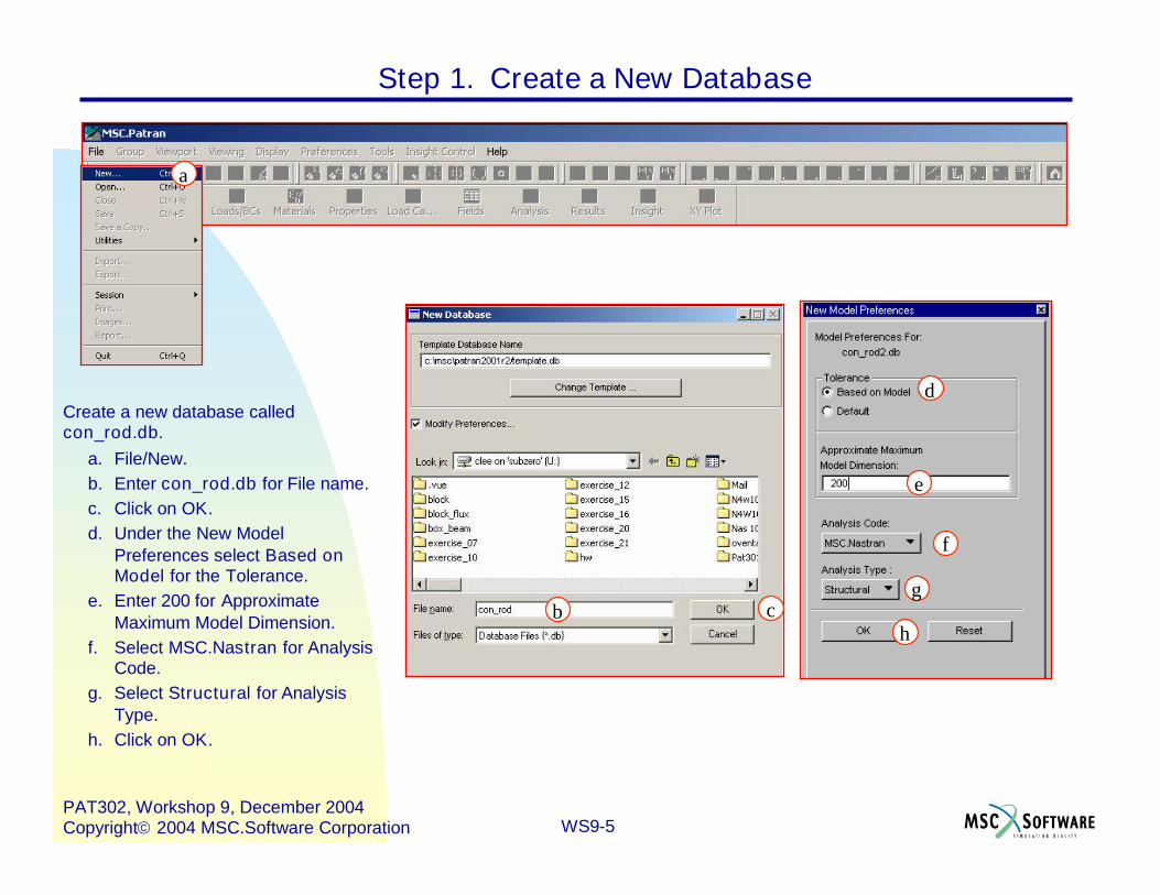
Step 1. Create a New Database
Create a new database calledcon_rod.db.
a. File/New.b. Enter con_rod.db for File name.c. Click on OK.d. Under the New Model
Preferences select Based onModel for the Tolerance.
e. Enter 200 for ApproximateMaximum Model Dimension.
f. Select MSC.Nastran for AnalysisCode.
g. Select Structural for AnalysisType.
h. Click on OK.
f
e
d
cb
a
h
g

WS9-6PAT302, Workshop 9, December 2004Copyright2004 MSC.Software Corporation
Step 2. Import the IGES File With Curves
Import the IGES file.a. File/Import…b. Set the Object and Source
to Model and IGES,respectively.
c. Find and selectcon_rod_new.igs for Filename.
d. Click on Apply.e. Click OK when the import
summary appears.
d
cb
a
WS9-7PAT302, Workshop 9, December 2004Copyright2004 MSC.Software Corporation
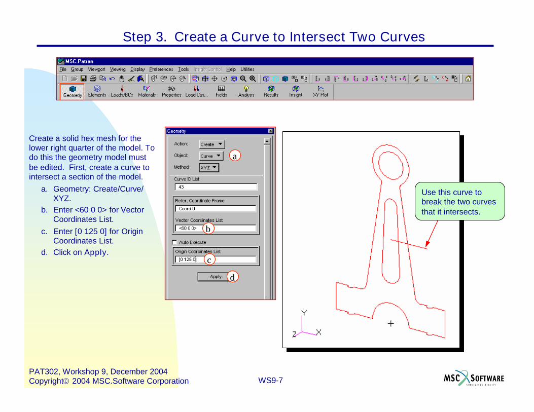
Create a solid hex mesh for thelower right quarter of the model. Todo this the geometry model mustbe edited. First, create a curve tointersect a section of the model.
a. Geometry: Create/Curve/XYZ.
b. Enter <60 0 0> for VectorCoordinates List.
c. Enter [0 125 0] for OriginCoordinates List.
d. Click on Apply.
Step 3. Create a Curve to Intersect Two Curves
d
c
b
a
Use this curve tobreak the two curvesthat it intersects.
WS9-8PAT302, Workshop 9, December 2004Copyright2004 MSC.Software Corporation
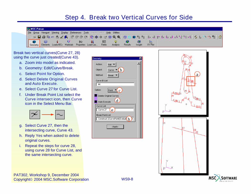
Break two vertical curves(Curve 27, 28)using the curve just created(Curve 43).
a. Zoom into model as indicated.b. Geometry: Edit/Curve/Break.c. Select Point for Option.d. Select Delete Original Curves
and Auto Execute.e. Select Curve 27 for Curve List.f. Under Break Point List select the
Curve intersect icon, then Curveicon in the Select Menu Bar.
g. Select Curve 27, then theintersecting curve, Curve 43.
h. Reply Yes when asked to deleteoriginal curves.
i. Repeat the steps for curve 28,using curve 28 for Curve List, andthe same intersecting curve.
Step 4. Break two Vertical Curves for Side
h
e
d
c
ba

WS9-9PAT302, Workshop 9, December 2004Copyright2004 MSC.Software Corporation
Step 5. Break the Breaking Curve
Now break horizontal curve, Curve 43, atthe point created at an intersection.
a. Select Delete Original Curvesand Auto Execute.
b. Select Curve 43 for Curve List.c. Select the point at intersection
between Curve 43 and Curve 45for Break Point List.
d. Click Yes when ask to delete theoriginal curves.
d
c
b
a
Curve 43
Point atIntersection
WS9-10PAT302, Workshop 9, December 2004Copyright2004 MSC.Software Corporation
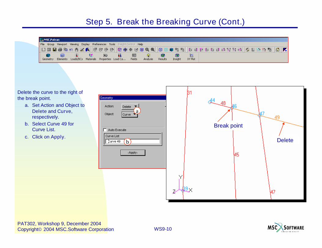
Delete the curve to the right ofthe break point.
a. Set Action and Object toDelete and Curve,respectively.
b. Select Curve 49 forCurve List.
c. Click on Apply.
Step 5. Break the Breaking Curve (Cont.)
b
a
Delete
Break point

WS9-11PAT302, Workshop 9, December 2004Copyright2004 MSC.Software Corporation
Step 6. Change the Geometric Shrink
Use the geometric shrink to makepicking the entities easier.
a. Display: Geometry…b. Using the slidebar set the
Geometric Shrink to 0.20.c. Click on Apply, then Cancel.d. Go to Front view.
a
c
b
WS9-12PAT302, Workshop 9, December 2004Copyright2004 MSC.Software Corporation
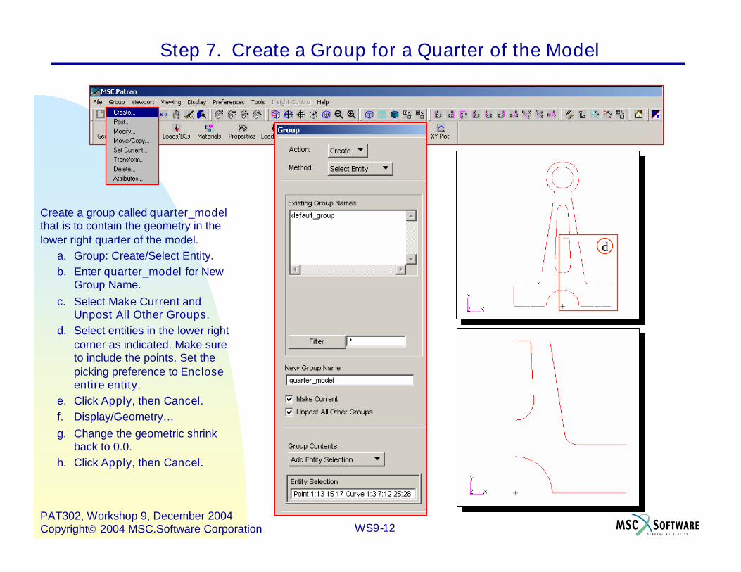
Create a group called quarter_modelthat is to contain the geometry in thelower right quarter of the model.
a. Group: Create/Select Entity.b. Enter quarter_model for New
Group Name.c. Select Make Current and
Unpost All Other Groups.d. Select entities in the lower right
corner as indicated. Make sureto include the points. Set thepicking preference to Encloseentire entity.
e. Click Apply, then Cancel.f. Display/Geometry…g. Change the geometric shrink
back to 0.0.h. Click Apply, then Cancel.
Step 7. Create a Group for a Quarter of the Model
e
cb
a
d

WS9-13PAT302, Workshop 9, December 2004Copyright2004 MSC.Software Corporation
Break Curve 33 using the parametricoption.
a. Turn on the curve labels, andincrease point size.
b. Geometry: Edit/Curve/Break.c. Set Option to Parametric.d. Enter 0.5 for Break Point.e. Select Delete Original Curves
and Auto Execute.f. Select Curve 33 for Curve List.g. Click Yes when asked to delete
the original curve.h. Turn on the point labels, and
turn off curve labels.
Step 8. Break a Fillet Curve
g
f
e
d
c
b
Curve 33
WS9-14PAT302, Workshop 9, December 2004Copyright2004 MSC.Software Corporation
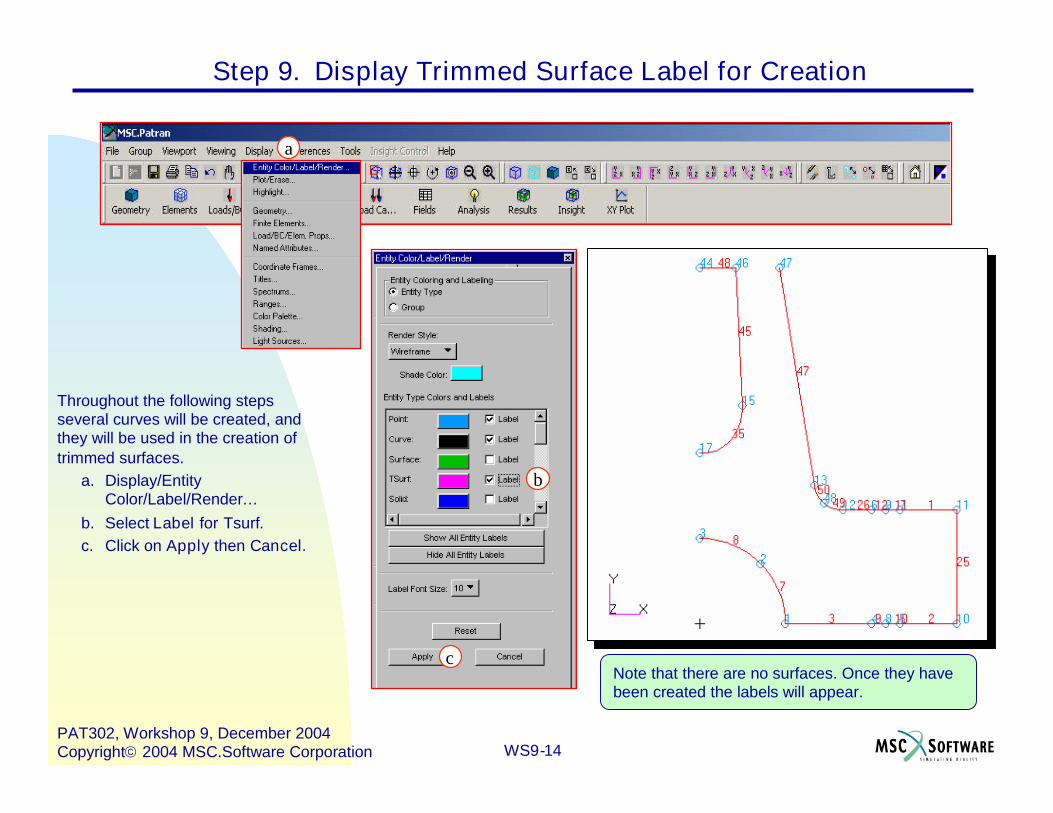
Step 9. Display Trimmed Surface Label for Creation
Throughout the following stepsseveral curves will be created, andthey will be used in the creation oftrimmed surfaces.
a. Display/EntityColor/Label/Render…
b. Select Label for Tsurf.c. Click on Apply then Cancel.
c
b
a
Note that there are no surfaces. Once they havebeen created the labels will appear.
WS9-15PAT302, Workshop 9, December 2004Copyright2004 MSC.Software Corporation
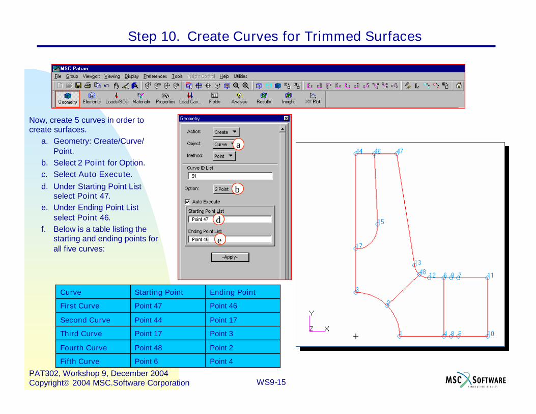
Now, create 5 curves in order tocreate surfaces.
a. Geometry: Create/Curve/Point.
b. Select 2 Point for Option.c. Select Auto Execute.d. Under Starting Point List
select Point 47.e. Under Ending Point List
select Point 46.f. Below is a table listing the
starting and ending points forall five curves:
e
d
b
a
Ending PointStarting PointCurve
Point 2Point 48Fourth Curve
Point 3Point 17Third Curve
Point 4Point 6Fifth Curve
Point 17Point 44Second Curve
Point 46Point 47First Curve
Step 10. Create Curves for Trimmed Surfaces

WS9-16PAT302, Workshop 9, December 2004Copyright2004 MSC.Software Corporation
Turn off the point labels, turn on thecurve labels, turn on the surfacelabels, and create trimmedsurfaces.
a. Turn off point labels, turn oncurve labels, and turn onsurface labels.
b. Geometry: Create/Surface/Trimmed.
c. Select Planar for Option.d. Click on Auto Chain…e. Select Current Group Only
and Highlight ChainCreation.
f. Deselect DeleteConstituent Curves.
g. Select Auto Execute.h. Select Curve 26 for Select a
Start Curve.i. Click on the OK and Next
buttons as needed.j. Cancel.
Step 11. Create Trimmed Surfaces
The goal is to create a chained curve (seeabove), then a trimmed surface. Use theNext button to select a different path, andthe OK button to accept the current path.
ii
h
g
e
fdc
b
Chainedcurve

WS9-17PAT302, Workshop 9, December 2004Copyright2004 MSC.Software Corporation
Create the first trimmed surface.a. Geometry: Create/Surface/
Trimmed.b. Select Planar for Option.c. Outer Loop List: select the
chained curve just created,e.g. Curve 56.
d. Apply.
Step 11. Create Trimmed Surfaces (Cont.)
WS9-18PAT302, Workshop 9, December 2004Copyright2004 MSC.Software Corporation
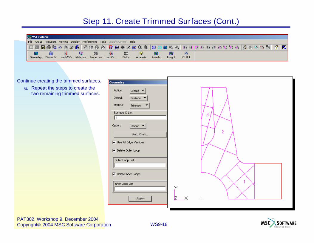
Continue creating the trimmed surfaces.a. Repeat the steps to create the
two remaining trimmed surfaces.
Step 11. Create Trimmed Surfaces (Cont.)
WS9-19PAT302, Workshop 9, December 2004Copyright2004 MSC.Software Corporation
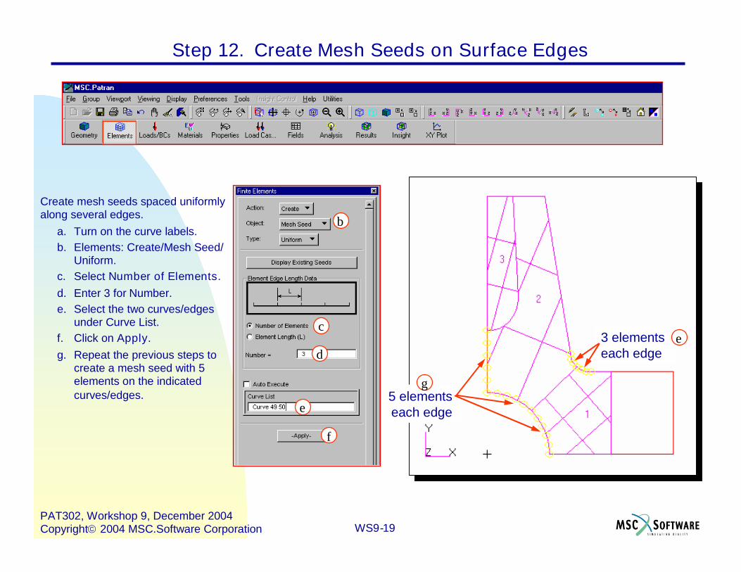
Create mesh seeds spaced uniformlyalong several edges.
a. Turn on the curve labels.b. Elements: Create/Mesh Seed/
Uniform.c. Select Number of Elements.d. Enter 3 for Number.e. Select the two curves/edges
under Curve List.f. Click on Apply.g. Repeat the previous steps to
create a mesh seed with 5elements on the indicatedcurves/edges.
Step 12. Create Mesh Seeds on Surface Edges
f
e
d
c
b
3 elementseach edge
5 elementseach edge
e
g
WS9-20PAT302, Workshop 9, December 2004Copyright2004 MSC.Software Corporation
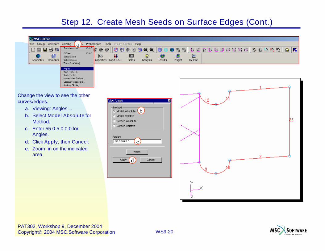
Change the view to see the othercurves/edges.
a. Viewing: Angles…b. Select Model Absolute for
Method.c. Enter 55.0 5.0 0.0 for
Angles.d. Click Apply, then Cancel.e. Zoom in on the indicated
area.
Step 12. Create Mesh Seeds on Surface Edges (Cont.)
d
c
b
a

WS9-21PAT302, Workshop 9, December 2004Copyright2004 MSC.Software Corporation
Create mesh seeds on additional edgesusing one way bias
a. Elements: Create/Mesh Seed/One Way Bias.
b. Select Num Elems and L2/L1.c. Enter 3 under Number.d. Enter 2 under L2/L1.e. Select Auto Execute.f. Select Curve 10 11 for Curve
List.g. Change the L2/L1 to 0.5.h. Select Curve 9 12 for Curve
List.i. Change to Front view and turn
off all labels.j. Use Fit view .
Step 12. Create Mesh Seeds on Surface Edges (Cont.)
a
b
f
dc
b

WS9-22PAT302, Workshop 9, December 2004Copyright2004 MSC.Software Corporation
Step 12. Create Mesh Seeds on Surface Edges (Cont.)
WS9-23PAT302, Workshop 9, December 2004Copyright2004 MSC.Software Corporation
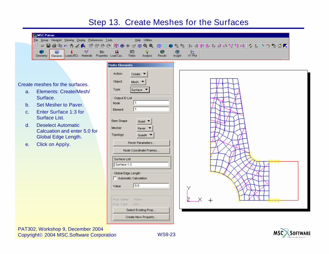
Create meshes for the surfaces.a. Elements: Create/Mesh/
Surface.b. Set Mesher to Paver.c. Enter Surface 1:3 for
Surface List.d. Deselect Automatic
Calcuation and enter 5.0 forGlobal Edge Length.
e. Click on Apply.
Step 13. Create Meshes for the Surfaces
e
c
b
d
a
WS9-24PAT302, Workshop 9, December 2004Copyright2004 MSC.Software Corporation
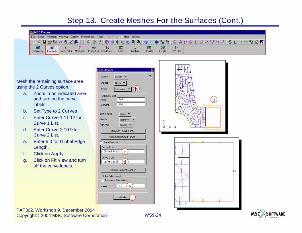
Mesh the remaining surface areausing the 2 Curves option.
a. Zoom in on indicated area,and turn on the curvelabels.
b. Set Type to 2 Curves.c. Enter Curve 1 11 12 for
Curve 1 List.d. Enter Curve 2 10 9 for
Curve 2 List.e. Enter 5.0 for Global Edge
Length.f. Click on Apply.g. Click on Fit view and turn
off the curve labels.
Step 13. Create Meshes For the Surfaces (Cont.)
f
d
c
e
b
a
WS9-25PAT302, Workshop 9, December 2004Copyright2004 MSC.Software Corporation
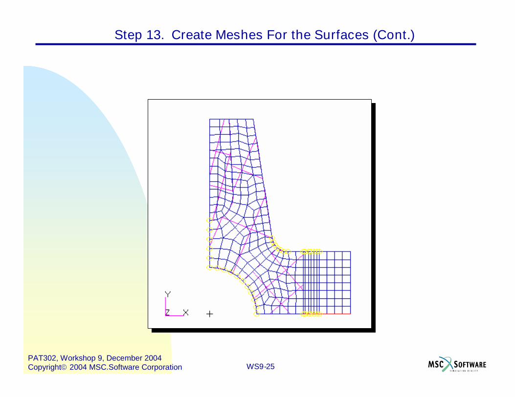
Step 13. Create Meshes For the Surfaces (Cont.)

WS9-26PAT302, Workshop 9, December 2004Copyright2004 MSC.Software Corporation
Create two lists. The first containing theelements associated with the connecting rodinner web, and the other containing theremaining elements associated with theother surfaces.
a. Tools/List/Create…b. Set the Model, Object, and Method to
FEM, Element, and Association,respectively.
c. Select Surface under Association.d. Select Surface 3 under Surface.e. Select A for the Target List.f. Click on Apply.g. Select Surfaces 1 & 2 for Surface.h. Change the Target List to B.i. Click on Apply, then Cancel.
Step 14. Create Lists for Sweeping to Create Solid Elements
f
e
d
c
b
a
i
h
g
WS9-27PAT302, Workshop 9, December 2004Copyright2004 MSC.Software Corporation
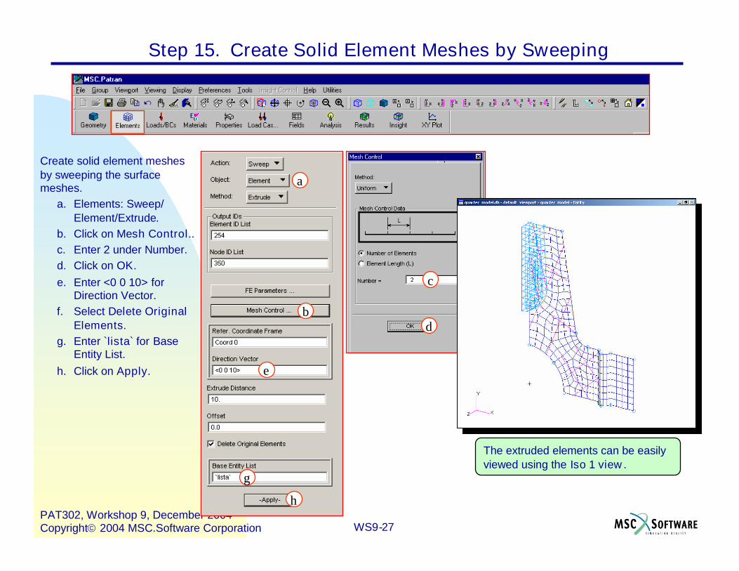
Create solid element meshesby sweeping the surfacemeshes.
a. Elements: Sweep/Element/Extrude.
b. Click on Mesh Control..c. Enter 2 under Number.d. Click on OK.e. Enter <0 0 10> for
Direction Vector.f. Select Delete Original
Elements.g. Enter `lista` for Base
Entity List.h. Click on Apply.
Step 15. Create Solid Element Meshes by Sweeping
The extruded elements can be easilyviewed using the Iso 1 view .
h
g
e
d
c
b
a

WS9-28PAT302, Workshop 9, December 2004Copyright2004 MSC.Software Corporation
Extrude the remaining surfaceelements.
a. Elements: Sweep/Element/Extrude.
b. Under Mesh Control enter4 under Number, and clickOK.
c. Enter <0 0 20> for DirectionVector.
d. Select Delete OriginalElements.
e. Enter `listb` for Base EntityList.
f. Click on Apply.g. Click on the Smooth
shaded icon.
Step 15. Create Solid Element Meshes by Sweeping (Cont.)
f
f
e
c
b
a

WS9-29PAT302, Workshop 9, December 2004Copyright2004 MSC.Software Corporation
Create a spatial vector field for extruding theremaining surface elements.
a. Fields: Create/Spatial/PCL Function.b. Enter direction_vector for Field Name.c. Select Vector for Field Type.d. Enter 0. for First Component.e. Enter 0. for Second Component.f. Enter 20.0-’Z for Third Component.g. Click on Apply.h. Set the display back to wire frame, and
select Front view.
Step 16. Create a Spatial Vector Field
g
fe
d
cb
a

WS9-30PAT302, Workshop 9, December 2004Copyright2004 MSC.Software Corporation
Create the remaining solid elements bysweeping the remaining surface elementsusing the vector field.
a. Elements: Sweep/Element/VectorField.
b. Under Mesh Control set Numberto 4, and click OK.
c. Enter direction_vector for FieldName.
d. Select Delete Original Elements.e. Select the remaining 2D elements,
that have not been swept, for BaseEntity List.
f. Click on Apply.g. Go to Iso 1 view.
Step 17. Create the Remainder of the Solid Elements
fe
d
c
b
a
e
WS9-31PAT302, Workshop 9, December 2004Copyright2004 MSC.Software Corporation
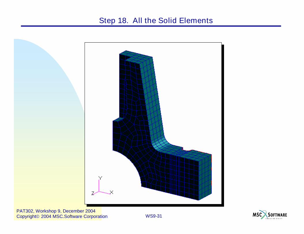
Step 18. All the Solid Elements
WS9-32PAT302, Workshop 9, December 2004Copyright2004 MSC.Software Corporation
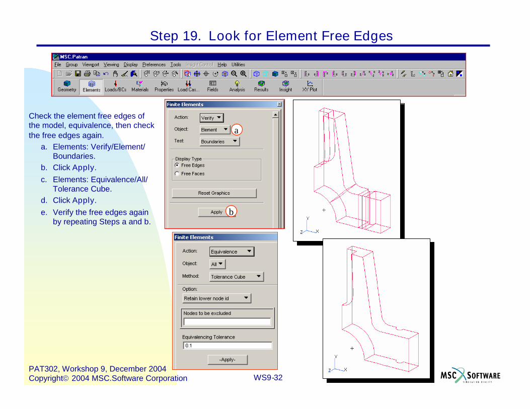
Check the element free edges ofthe model, equivalence, then checkthe free edges again.
a. Elements: Verify/Element/Boundaries.
b. Click Apply.c. Elements: Equivalence/All/
Tolerance Cube.d. Click Apply.e. Verify the free edges again
by repeating Steps a and b.
d
c
a
b
Step 19. Look for Element Free Edges

WS9-33PAT302, Workshop 9, December 2004Copyright2004 MSC.Software Corporation
Change the display to hidden line while stillin the verify mode.
a. Click on the Hidden line icon.
a
Step 19. Look for Element Free Edges (Cont.)

WS9-34PAT302, Workshop 9, December 2004Copyright2004 MSC.Software Corporation
Quite MSC.PATRAN.a. File : Close.
This ends this exercise.
Step 20. Quit MSC.Patran
a