workshop manual elect, ignit and fuel
TRANSCRIPT

��������� �� ������������ ���� ����
�
����


iElect/eng
ContentsGeneral Information.........................................................
Cranking System ..............................................................
Charging System .............................................................
Trim/Tilt Electrical System ...............................................
Ignition System Delco EST ..............................................
Ignition System Prestolite® B.I.D. ...................................
Fuel System - Carbureted Models ...................................
Safety ................................................................................
1
2
3
4
5
6
7
S

iiElect/eng

iiiElect/eng
M All stern drive system components must be matched for either single ordual engine installations. Failure to properly match engine, transom bracketand vertical drive will result in poor boat performance, and risk damage toengine and drive because of incorrect drive gear ratio.
Model identification is located on the engine valve cover, and MUST corre-spond with the transom bracket and vertical drive numbers as listed in thisdocument.
• Engine Model Number 1 2 3
• Transom Bracket Model Number 4
• Vertical Drive Model Number 5
Model Identification
DR1145
DR4282
DR6815
DR2058
DR4957
1
2
4
5
3

ivElect/eng

1-1Elect/eng
Section 1General Information
Table of Contents
Battery and Cables ............................................................................. 1-8Circuit Protection ............................................................................. 1-12Circuit Protectors and Locations .................................................... 1-13Connector Service
Amphenol ...................................................................................... 1-19Packard .......................................................................................... 1-21
Conversion ChartsDrill ................................................................................................. 1-31Metric ............................................................................................. 1-30
Gasoline Requirements ..................................................................... 1-6Gasolines Containing Alcohol .......................................................... 1-7Ignition Switch .................................................................................. 1-18Introduction ........................................................................................ 1-3Oil and Water Sending Units ........................................................... 1-14Periodic Maintenance Chart ............................................................ 1-33Relays ................................................................................................ 1-11Sealants, Lubricants and Adhesives ................................................ 1-2Solenoids .......................................................................................... 1-10Spark Plugs and Leads .................................................................... 1-16Special Tools ...................................................................................... 1-2Symbols ............................................................................................ 1-32Torque Specifications, General ....................................................... 1-34Troubleshooting
Engine Troubleshooting Guides .................................................. 1-23System Isolation............................................................................ 1-22
Tachometer ....................................................................................... 1-18Tuning the Engine .............................................................................. 1-5
Safety Warnings
Before working on any part of the electrical system, read the sec-tion called Safety at the end of this manual.
The original mounting, support and routing of electrical systemparts conform with U.S. Coast Guard requirements. It is importantto maintain the original mounting, support and routing after ser-vicing the electrical system to prevent possible fire and explosionin boat’s engine compartment.
Do not substitute automotive parts. Volvo Penta marine compo-nents meet U.S. Coast Guard regulations for external ignition proofoperation and marine use. Volvo Penta marine components arespecially designed not to cause ignition of fuel vapors in the bilgeor engine compartment. The use of automotive parts can result infire and explosion.
1

1-2 Elect/eng
Special Tools
Tool Name Part No. Panel LocationCrimping Pliers - BInsert Tool 3854349-2 BPin Remover - BSocket Remover 3854350-0 B
Sealants, Lubricants and Adhesives
DuraPlusTM Marine Fuel ConditionerBlack neoprene dipIsopropyl alcoholTerminal grease

1-3Elect/eng
Introduction
This service manual is divided into sections concerning various sys-tems and assemblies. Refer to the Contents to locate the section cov-ering the system or assembly requiring service. Each section title pagehas an additional listing that will describe the section’s contents in moredetail. Be sure to read the Safety Section at the end of this manual,and pay special attention to all safety warnings as they appear through-out the text. Since models are subject to change at any time, somephotos may not depict actual product.
Good Service Practice
Service required for stern drives is generally one of three kinds:
• Normal care and maintenance - which includes putting anew stern drive into operation, storing engines, lubrica-tion, and care under special operating conditions such assalt water and cold weather.
• Operating malfunctions - due to improper engine or drivemounting, propeller condition or size, boat condition, orthe malfunction of some part of the engine. This includesengine servicing procedures to keep the engine in primeoperating condition.
• Complete disassembly and overhaul - such as majorservice or rebuilding a unit.
It is important to determine before disassembly just what the trouble isand how to correct it quickly, with minimum expense to the owner.
When repairing an assembly, the most reliable way to ensure a goodjob is to do a complete overhaul on that assembly, rather than just toreplace the bad part. Wear not readily apparent on other parts couldcause malfunction soon after the repair job. Repair kits and seal kitscontain all the parts needed to ensure a complete repair, to eliminateguesswork, and to save time.
Repair time can also be minimized by the use of special tools. VolvoPenta special tools are designed to perform service procedures uniqueto the product that cannot be completed using tools from other sources.They also speed repair work to help achieve service flat rate times. Insome cases, the use of substitute tools can damage the part.
Do not operate engine out of water even momentarily. Ifoperated in test tank, use proper test wheel. Failure to do so can dam-age water pump, overheat engine, or allow excessive engine RPM.

1-4 Elect/eng
Preparation for Service
Proper preparation is extremely helpful for efficient service work. Aclean work area at the start of each job will minimize tools and partsbecoming misplaced. Clean an engine that is excessively dirty beforework starts. Cleaning will occasionally uncover trouble sources. Ob-tain tools, instruments and parts needed for the job before work isstarted. Interrupting a job to locate special tools or repair kits is a need-less delay.
Use proper lifting and handling equipment. Working on sterndrives without proper equipment can cause damage and personalinjury.
Always use clean fresh fuel when testing engines. Troubles can oftenbe traced to the use of old or dirty fuel.
Service Policy
It is a policy of Volvo Penta to provide dealers with service knowledgeso they can give professional service demanded by today’s consumer.The Volvo Penta Training Centers, frequent mailing of Service Bulle-tins, Letters and Promotions, Special Tools and this Service Manualrepresent our continuing efforts to assist dealers in giving consumersthe best and most prompt service possible. If a service question doesnot appear to be answered in this manual, you are invited to write tothe Volvo Penta Service Department for additional help. Always besure to give complete information, including engine model number andserial number.
When a brand-name product or specific tool is called for, another itemmay be used. However, the substitute must have equivalent charac-teristics, including type, strength, and material. You must determine ifincorrect substitution could result in product malfunction and personalinjury to anyone. To avoid hazards, equivalent products which are usedmust meet all current U.S. Coast Guard Safety Regulations and ABYCstandards.
Safety Related

1-5Elect/eng
Replacement Parts
When replacement parts are required, always use genuineVolvo Penta parts, or parts with equivalent characteristics, includ-ing type, strength, and material. Failure to do so may result in prod-uct malfunction and possible injury to the operator and/or passen-gers.
Parts Catalogs
Parts catalogs contain exploded views showing the correct assembly ofall parts, as well as a complete listing of the parts for replacement. Thesecatalogs are helpful as a reference during disassembly and reassem-bly, and are available from Volvo Penta parts order.
Special Service Tools
Volvo Penta has specially designed tools to simplify some of the disas-sembly and assembly operations. These tools are illustrated in this Ser-vice Manual, in many cases in actual use. All Volvo Penta special toolscan be ordered from Volvo Penta parts order. Individual purchasers ofService Manuals must order Special Tools through an authorized dealer.
Product References, Illustrations & Specifications
Volvo Penta reserves the right to make changes at anytime, withoutnotice, in specifications and models and also to discontinue models.The right is also reserved to change any specifications or parts at anytime without incurring any obligation to equip same on models manu-factured prior to date of such change. All information, illustrations andspecifications contained in this manual are based on the latest productinformation available at the time of printing. The right is reserved tomake changes at anytime without notice.
All photographs and illustrations used in this manual may not depictactual models or equipment, but are intended as representative viewsfor reference only. The continuing accuracy of this manual cannot beguaranteed.
Tuning The Engine
The purpose of an engine tune-up is to restore power and performancethat has been lost through wear, corrosion or deterioration of one ormore parts or components. In the normal operation of an engine, thesechanges can take place gradually at a number of points, so that it isseldom advisable to attempt an improvement in performance by correc-tion of one or two items only. Time will be saved and more lasting re-sults will be obtained by following a definite and thorough procedure ofanalysis and correction of all items affecting power and performance.Refer to the Engine Service Manual for all tune-up specifications.
Safety Related

1-6 Elect/eng
Gasoline Requirements
Stern drive models in this manual are designed for maximum perfor-mance with the use of gasoline with the following minimum or higheroctane specification:
• Anti-Knock Index Number (AKI) - 89
• Research Octane Number (RON) - 93
EFI Models Only: Some marinas sell fuel with lead additives. Do notuse such fuel as it may plug the fuel injectors. Premium grade fu-els contain injector cleaners and other additives that protect the fuelsystem and provide optimum performance. The use of premium gradefuels is strongly recommended.
Carbureted Models Only: Use of lead-free or leaded gasoline is ac-ceptable.
If fuels with 89 AKI (93 RON) octane or higher are not available, loweroctane fuels, with a minimum of 86 AKI (90 RON) octane, can be used.Some engines may require timing adjustments if fuels lower than89 AKI (93 RON) octane are used. See the General Informationsection of the Engine Service Manual. When lower octane fuels areused, a slight decrease in power can be expected.
Engine damage resulting from the use of gasoline with octanelower than 86 AKI (90 RON) is considered misuse of the engine andwill void the engine warranty. Volvo Penta suggests the use of 89 AKIor higher fuels. These fuels have additives that are beneficial to maxi-mum engine performance and long life of service components.
To prevent gum formation and corrosion in the fuel system, useDuraPlusTM Marine Fuel conditioner in the gasoline. DuraPlusTM Ma-rine Fuel conditioner is available from your authorized dealer.
Gasoline is extremely flammable and highly explosive undercertain conditions. Always stop engine and do not smoke or al-low open flames or sparks near the boat when refueling gas tanks.When filling the gas tank, ground the tank to the source of gaso-line by holding the hose nozzle firmly against the side of the deckfiller plate, or ground it in some other manner. This action pre-vents static electricity build-up which could cause sparks and ig-nite fuel vapors.
Safety Related

1-7Elect/eng
Gasolines Containing Alcohol
Many gasolines being sold today contain alcohol. Two commonly usedalcohol additives are Ethanol (ethyl alcohol) and Methanol (methyl al-cohol).
See the Owner’s Manual for your boat to determine if the boat’s fuelsystem is compatible with alcohol blended fuels. If it is compatible, yourengine may be operated using gasolines blended with no more than10% Ethanol (ethyl alcohol) meeting the minimum octane specification.Do not use any gasoline which contains METHANOL (methyl alco-hol).
Serious damage to the boat or engine fuel systems will resultfrom the continued use of fuel containing METHANOL (methyl alcohol).
If you use gasoline containing alcohol, be aware of the following:
• The engine will operate leaner with alcohol blended fuel.This may cause engine problems such as vapor lock, lowspeed stall, or hard starting.
• Alcohol blended fuels attract and hold moisture. Moistureinside fuel tanks can cause corrosion of the tank material.Inspect fuel tanks at least annually. Replace fuel tanks ifinspection indicates leakage or corrosion.
• Inspect non-metallic parts of fuel system frequently andreplace if excessive stiffness, deterioration or fuel leakageis found.
Fuel leakage can contribute to a fire and/or explosion.
Safety Related

1-8 Elect/eng
Battery and Cables
Special Tools Required: Battery Hydrometer
The primary function of the battery is to provide power to operate thestarter motor. The battery also supplies power to operate the lightsand other electrical equipment which may be used when the engine isnot running. On battery ignition systems, the battery must supply theignition current during the starting period and during the time that thealternator is not producing a sufficient charge to meet operating re-quirements.
Battery Requirements
3.0 GS, 4.3 GL & GS MODELS ONLY
• Use a 12 volt battery having a minimum rating of 360Cold Cranking Amps at 0° F (-18° C), and a 115 minutereserve capacity rating at 80° F (27° C).
ALL OTHER MODELS
• Use a 12 volt battery having a minimum rating of 650Cold Cranking Amps at 0° F (-18° C), and a 165 minutereserve capacity rating at 80° F (27° C).
Battery Maintenance
There are two things which must be done periodically in order to ob-tain long life from a battery.
1. The electrolyte must be kept above the plates and separators at alltimes. The liquid level should be brought up to the level specified bythe battery manufacturer. Acid should never be added except when itis definitely known that some has been lost by spilling, and then onlyby an experienced battery man.
Battery electrolyte is a corrosive acid and should be handledwith care. If electrolyte is spilled or splashed on any part of thebody, immediately flush the exposed area with liberal amounts ofwater and obtain medical aid as soon as possible.
1 2. Be sure that the battery is kept nearly at full charge at all times.The state of charge should be checked at frequent intervals by makingspecific gravity readings with a battery hydrometer. It is suggestedthat gravity readings and replacement of evaporated water be madeevery two weeks. Should the gravity fall more than 0.040 specific gravitybelow a fully charged gravity reading, remove the battery and have itcharged.
Full charge specific gravity is 1.260 at 80° F (27° C).
Do not use a jumper cable and a booster battery to start en-gine. Remove battery from boat and recharge. Fumes vented dur-ing charging battery can lead to an explosion.
Safety Related
DR3201
1

1-9Elect/eng
Good Battery Servicing Includes the Following Nine Points:
a. Protect boat against acid damage.b. Clean battery.c. Inspect cables.d. Clean terminals.e. Inspect hold-downs.f. Inspect casing for leaks.g. Make hydrometer test.h. Remove battery from boat for tests. Recharge battery if less
than 3/4 charged. Make load test.i. Add water.
If battery is not in a good state of charge or if it uses an excessiveamount of water, check the charging system.
Clean the battery and terminals with a solution of baking soda and wa-ter. This will neutralize the acid on the battery. After washing with thissolution, flush top of battery with clear water. Care must be taken whenwashing the battery so that the baking soda and water solution does notenter the battery cells.
Cable Requirements
The battery should be mounted as close to the engine as practical tocut down on battery cable lengths. Follow the recommendations below.
• 0-10 Feet 0 Gauge
• 10-15 Feet 2/0 Gauge
• 15-20 Feet 4/0 Gauge
These specifications do not apply to aluminum battery cables.Volvo Penta does not recommend the use of aluminum battery cables.
To prevent possible explosion or fire, do not substitute auto-motive parts for the following marine components: starter, alterna-tor, distributor and related ignition parts, spark plug leads, sole-noids, carburetor (and related parts), fuel pump or fuel filter canis-ter. These components have been specifically designed not to emitfuel vapors or to cause ignition of fuel vapors in the bilge.
Safety Related
1-10 Elect/eng
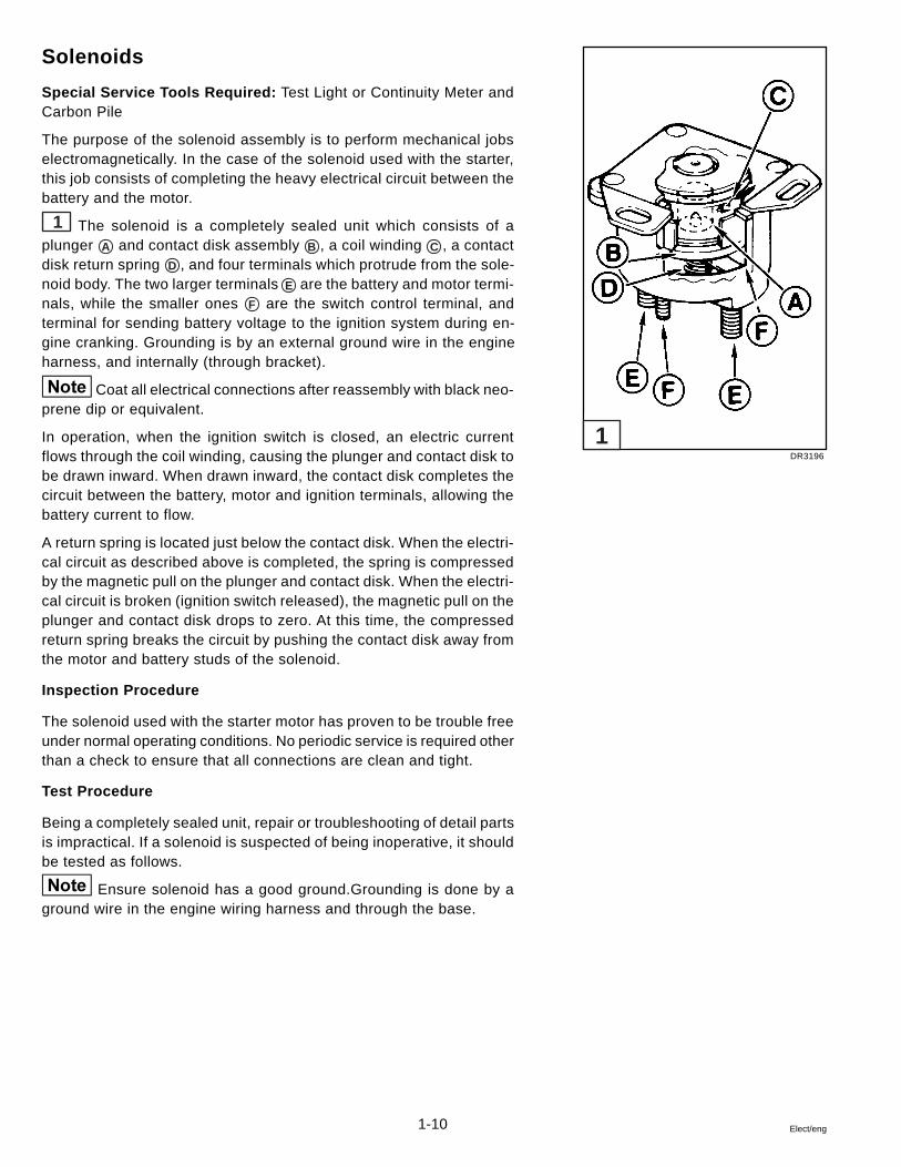
Solenoids
Special Service Tools Required: Test Light or Continuity Meter andCarbon Pile
The purpose of the solenoid assembly is to perform mechanical jobselectromagnetically. In the case of the solenoid used with the starter,this job consists of completing the heavy electrical circuit between thebattery and the motor.
1 The solenoid is a completely sealed unit which consists of aplunger A and contact disk assembly B , a coil winding C , a contactdisk return spring D , and four terminals which protrude from the sole-noid body. The two larger terminals E are the battery and motor termi-nals, while the smaller ones F are the switch control terminal, andterminal for sending battery voltage to the ignition system during en-gine cranking. Grounding is by an external ground wire in the engineharness, and internally (through bracket).
Coat all electrical connections after reassembly with black neo-prene dip or equivalent.
In operation, when the ignition switch is closed, an electric currentflows through the coil winding, causing the plunger and contact disk tobe drawn inward. When drawn inward, the contact disk completes thecircuit between the battery, motor and ignition terminals, allowing thebattery current to flow.
A return spring is located just below the contact disk. When the electri-cal circuit as described above is completed, the spring is compressedby the magnetic pull on the plunger and contact disk. When the electri-cal circuit is broken (ignition switch released), the magnetic pull on theplunger and contact disk drops to zero. At this time, the compressedreturn spring breaks the circuit by pushing the contact disk away fromthe motor and battery studs of the solenoid.
Inspection Procedure
The solenoid used with the starter motor has proven to be trouble freeunder normal operating conditions. No periodic service is required otherthan a check to ensure that all connections are clean and tight.
Test Procedure
Being a completely sealed unit, repair or troubleshooting of detail partsis impractical. If a solenoid is suspected of being inoperative, it shouldbe tested as follows.
Ensure solenoid has a good ground.Grounding is done by aground wire in the engine wiring harness and through the base.
DR3196
1
1-11Elect/eng
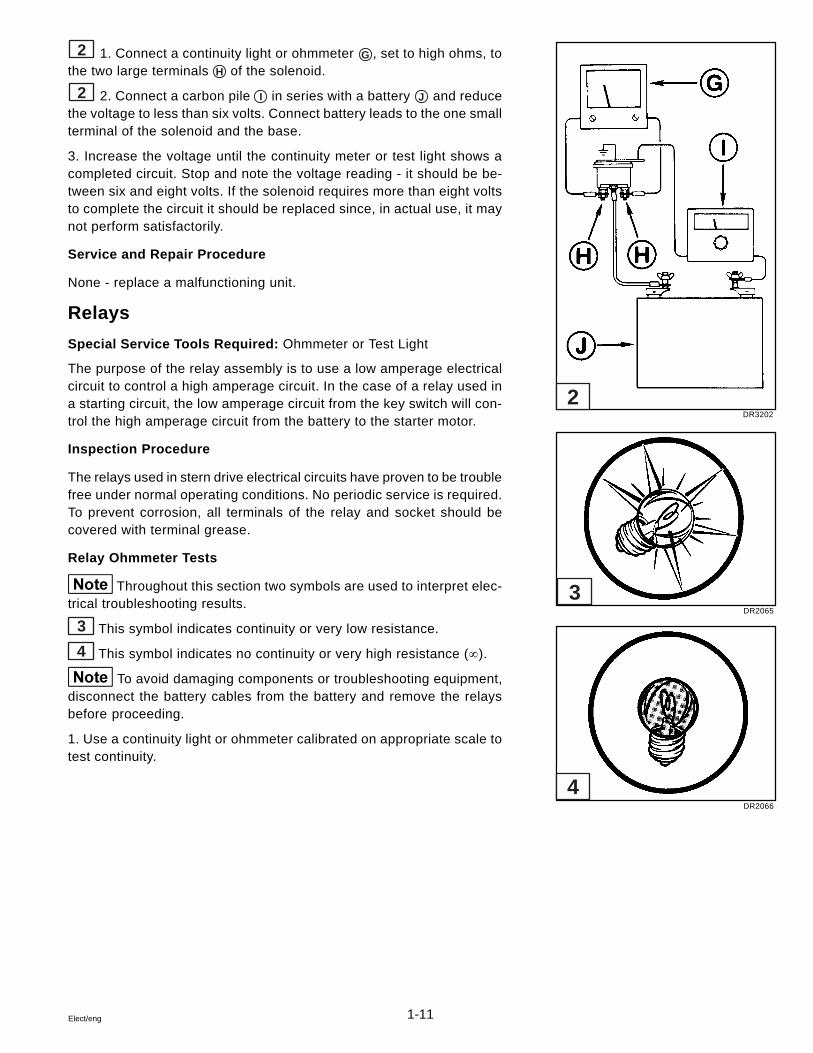
2 1. Connect a continuity light or ohmmeter G , set to high ohms, tothe two large terminals H of the solenoid.
2 2. Connect a carbon pile I in series with a battery J and reducethe voltage to less than six volts. Connect battery leads to the one smallterminal of the solenoid and the base.
3. Increase the voltage until the continuity meter or test light shows acompleted circuit. Stop and note the voltage reading - it should be be-tween six and eight volts. If the solenoid requires more than eight voltsto complete the circuit it should be replaced since, in actual use, it maynot perform satisfactorily.
Service and Repair Procedure
None - replace a malfunctioning unit.
Relays
Special Service Tools Required: Ohmmeter or Test Light
The purpose of the relay assembly is to use a low amperage electricalcircuit to control a high amperage circuit. In the case of a relay used ina starting circuit, the low amperage circuit from the key switch will con-trol the high amperage circuit from the battery to the starter motor.
Inspection Procedure
The relays used in stern drive electrical circuits have proven to be troublefree under normal operating conditions. No periodic service is required.To prevent corrosion, all terminals of the relay and socket should becovered with terminal grease.
Relay Ohmmeter Tests
Throughout this section two symbols are used to interpret elec-trical troubleshooting results.
3 This symbol indicates continuity or very low resistance.
4 This symbol indicates no continuity or very high resistance (¥).
To avoid damaging components or troubleshooting equipment,disconnect the battery cables from the battery and remove the relaysbefore proceeding.
1. Use a continuity light or ohmmeter calibrated on appropriate scale totest continuity.
DR3202
DR2065
DR2066
2
3
4

1-12 Elect/eng
1 2. Connect meter leads to relay terminals 87a and 30.
• The meter must show continuity.
2 3. Connect meter leads to relay terminals 87 and 30.
• The meter must show no continuity.
3 4. Calibrate an ohmmeter on appropriate scale and connect theleads to relay terminals 85 and 86.
• The meter must show 70 - 100 ohms.
4 5. Connect meter leads to relay terminals 87 and 30. Connect a12 volt source to relay terminals 85 and 86.
• The meter must show continuity.
5 6. Connect meter leads to relay terminals 87a and 30. Connect a12 volt source to relay terminals 85 and 86.
• The meter must show no continuity.7. Replace relay if your test results vary.
Circuit Protection
Do not attempt to connect or disconnect any part of the elec-trical circuit while the engine is running.
When installing additional electrical accessories always use individualfused circuits. Power takeoff should be made at a terminal strip pow-ered by auxiliary accessory wire and protected by a 30 amp (maxi-mum) fuse.
Safety Related
DR2149
DR2149A
DR2149B
DR2149C
DR2149D
5
4
3
2
1

1-13Elect/eng
Circuit Protectors and Locations
10 Amp Fuse *
Protects trim switch. Located on trim/tilt pump.
SFE 20 Amp Fuse *
Protects ignition switch. Located under dash.
6 Amp Circuit Breaker ê
Protects fuel pump. Located at starboard front of engine on fuel pump bracket.
15 Amp Fuse �
Protects ignition/injector relay and ECM. Located at front of starboard high-rise exhaust elbow
20 Amp Fuse �
Protects fuel pumps. Located at port front of engine.
50 Amp Circuit Breaker *
Protects trim/tilt motor. Located at front of starboard high-rise exhaust elbow.
40 Amp fuse *
Protects main harness. Located at front of starboard high-rise exhaust elbow.
* All Models
ê 4.3 GL, 5.0 GL, and 5.7 GS Models Only
� All Gi and GSi Models Only

1-14 Elect/eng
Oil and Water Sending Units
Special Tools Required: Ohmmeter
Inspection Procedure
Check wiring and connections between senders and gauges. Checkto see that senders are operating properly. Inspect orifice in oil pres-sure sender for blockage.
Test Procedure - Gauge Sending Units
Oil Pressure Sender: To check oil gauge senders, start engine andrun up from slow to fast. Observe gauge. If reading is unsatisfactory,check sender with an ohmmeter:
• 0 PSI ... 227-257 ohms
• 40 PSI ... 92-114 ohms
• 80 PSI ... 21.5-49.5 ohms
Replace sender with a new one if it fails the ohmmeter checks. Retest;if reading is still unsatisfactory, problem may be in gauge, engine lu-brication system or excessive bearing wear. Refer to appropriate En-gine Section, paragraph Oil Pump Service.
To check gauge, disconnect wire at sender, turn ignition switch on,and momentarily ground sender wire. Gauge needle will peg at highside of scale if gauge is operating properly.
Water Temperature Sender: To check water temperature senders,remove sender from engine. Connect sender to a digital ohmmeter.Immerse sender in a container of oil with a cooking thermometer. Heatoil over a flameless source. Observe meter and thermometer. Metershould indicate:
• 448 ohms ± 10% at 100° F (38° C)
• 128 ohms ± 7.5% at 160° F (71° C)
• 46.6 ohms ± 5% at 220° F (105° C)

1-15Elect/eng
Test Procedures - Audible Warning Switches (if equipped)
Oil Pressure Switch: The oil pressure audible warning switch is cali-brated to make or break contact at 4 ± 2 PSI (27,6 ± 13,8 kPa). Use anohmmeter to make the following continuity checks. Replace the switchif it fails either of these tests.
1. With the engine off and the switch wire disconnected, there shouldbe a full continuity (zero) reading between the switch terminal and en-gine block.
2. With the engine running and switch wire disconnected, there shouldbe no continuity (infinity) reading between the switch terminal and en-gine block.
Water Ternperature Switch: The water temperature audible warningswitch is calibrated to make or break contact at 200° ± 5° F (93° ± 5° C).Attach an ohmmeter to the switch and make the following check. Re-place the switch if it fails this test.
1. Immerse switch in a container of oil. Heat oil over a flameless sourceand check temperature with a cooking thermometer.
2. Below the make/break temperature, the ohmmeter should show a nocontinuity (infinity) reading. Above the make/break temperature, the ohm-meter should show a full continuity (zero) reading.
Test Procedure - Audible Warning Horn (if equipped)
Under normal conditions, horn will sound when ignition is turnedon. Horn will continue to sound until engine is started and oil pressureexceeds 4 ± 2 PSI (27,6 ± 13,8 kPa).
The dash mounted audible warning horn can be tested as follows. Re-place the horn if it fails this test.
1. Turn ignition switch to the ON position. Do not start engine.
2. If horn does not sound, disconnect the lead at the water temperatureaudible warning switch, and momentarily touch lead terminal to engineblock. If audible warning horn does not sound, horn is defective, or wir-ing of switch-horn-ignition switch circuit has lost continuity.
3. Disconnect the lead at the oil pressure audible warning switch, andmomentarily touch lead terminal to engine block. If audible warning horndoes not sound, horn is defective, or wiring of switch-horn-ignition switchcircuit has lost continuity.

1-16 Elect/eng
Spark Plugs and Leads
Removal and Inspection
1. To disconnect wires, twist and pull only on boot because pulling onwire may cause separation of the core of the wire. Remove spark plugsusing a 5/8 in. spark plug socket or a 5/8 in. box wrench. Use care toavoid cracking the spark plug insulators.
2. Carefully inspect the insulators and electrodes of all spark plugs.Replace any spark plug which has a cracked or broken insulator orwhich has loose electrodes. If the insulator is worn away around thecenter electrode, or the electrodes are burned or worn, the spark plugis worn out and should be discarded. Spark plugs which are in goodcondition, except for carbon or oxide deposits, should be thoroughlycleaned and gapped.
3. The spark plug wires are a special resistance type. The core is car-bon impregnated linen. This type wire is superior to copper core wirein its resistance to cross-fire; however, it is more easily damaged thancopper core. For this reason, care must be taken so that the sparkplug wires are removed by pulling on the spark plug boots rather thanon the wire insulation. If the wire is stretched, the core may be brokenwith no evidence of damage on the outer insulation. If the core is bro-ken, it will cause misfiring. In the case of wire damage, it is necessaryto replace the complete wire assembly since a satisfactory repair can-not be made.
4. Use an ohmmeter to test ignition leads for excessive high resis-tance or an open circuit. Proper resistance is 3,000-7,000 ohms perfoot.
5. Clean ignition wires with a cloth moistened in kerosene, andwipe dry. Bend wires to check for brittle, cracked or loose insulation.Defective insulation will permit misfiring, cross-firing, or spark toground, therefore defective wires must be replaced.
6. If the wires are in good condition, clean any terminals that are cor-roded and replace any that are broken or distorted. Replace any wireswith broken or deteriorated cable nipples or spark plug boots.
Spark Plug Cleaning
Spark plugs which have carbon or oxide deposits should be cleanedin a blast type spark plug cleaner. Scraping with a pointed tool will notproperly remove the deposits and may damage the insulator. If sparkplugs have a wet or oily deposit, dip them in a degreasing solvent anddry thoroughly with compressed air. Oily plugs will cause the cleaningcompound to pack in the shell.
Safety Related

1-17Elect/eng
Carefully follow the instructions of the manufacturer of the cleaner be-ing used. Clean each plug until the interior of shell and entire insulatoris cleaned. Avoid excessive blasting.
1. Examine interior of plug in good light. Remove any cleaning com-pound with compressed air. If traces of carbon or oxide remain in plug,finish the cleaning with a light blasting operation. Clean firing surfacesof center and side electrodes with several strokes of a fine cut file.
2. When spark plugs have been thoroughly cleaned, carefully inspectthem for cracks or other defects which may not have been visible be-fore cleaning.
Adjust Spark Plug Gap
Use a round wire feeler gauge to check the gap between the spark plugelectrodes. Flat feeler gauges will not give a correct measurement if theelectrodes are worn. Adjust gap by bending the side electrode only.Bending the center electrode will crack the insulator. Setting the sparkplug gap to any other specification in an attempt to improve idle or af-fect engine performance is not recommended.
Installation of Spark Plugs and Wires
• 3.0 GS Models 1
• All V6 Models 2
• All V8 Models 3For proper engine performance it is very important that the correct sparkplugs be used. When installing spark plugs, make sure that the threadsin the cylinder head and all surfaces on plugs and in cylinder heads areclean. Tighten spark plugs the specified amount. All engines use ta-pered seat plugs without gaskets.
Do not operate engine if spark plug boots or high tension leadsare torn or cracked. This condition can allow external sparks whichcould ignite any fuel vapors in the engine compartment.
Spark plug wires must be arranged between the distributor cap andspark plugs in the order of firing sequence. If spark plug wires are notcorrectly installed, misfiring or cross-firing will result.
Safety Related
DR2451
DR2448
DR2453
1
2
3
1-18 Elect/eng
Ignition Switch
Special Tools Required: Continuity Light or Meter
Inspection Procedure
Check for loose connections, loose or corroded terminals. Check forcorrect wiring.
Test Procedure
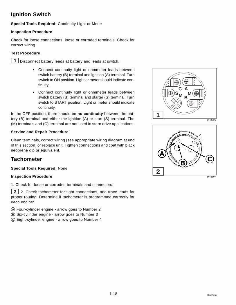
1 Disconnect battery leads at battery and leads at switch.
• Connect continuity light or ohmmeter leads betweenswitch battery (B) terminal and ignition (A) terminal. Turnswitch to ON position. Light or meter should indicate con-tinuity.
• Connect continuity light or ohmmeter leads betweenswitch battery (B) terminal and starter (S) terminal. Turnswitch to START position. Light or meter should indicatecontinuity.
In the OFF position, there should be no continuity between the bat-tery (B) terminal and either the ignition (A) or start (S) terminal. The(M) terminals and (C) terminal are not used in stern drive applications.
Service and Repair Procedure
Clean terminals, correct wiring (see appropriate wiring diagram at endof this section) or replace unit. Tighten connections and coat with blackneoprene dip or equivalent.
Tachometer
Special Tools Required: None
Inspection Procedure
1. Check for loose or corroded terminals and connectors.
2 2. Check tachometer for tight connections, and trace leads forproper routing. Determine if tachometer is programmed correctly foreach engine:
A Four-cylinder engine - arrow goes to Number 2B Six-cylinder engine - arrow goes to Number 3C Eight-cylinder engine - arrow goes to Number 4
DR3206
DR3197
CSM M
B
A
1
2

1-19Elect/eng
Amphenol Connector Service
Terminal Removal
Use the recommended luricant for terminal removal. Substitutesmay cause high resistance connections or short circuits between termi-nals, or adversely affect the connector material.
1. To remove a terminal from the plug or receptacle, lubricate it by ap-plying isopropyl alcohol to both ends of the cavity.
3 2. Select the proper removal tool for the terminal:
D Pin RemoverE Socket Remover,
P/N 3854350-0
3. Place the plug or receptacle against the edge of a flat surface andallow clearance for the terminal to be removed.
4 4. Insert the removal tool into the terminal and push the terminalfrom the connector.
5 5. Pin F and socket G terminals may be replaced if damaged.Crimp new terminals onto the wire at point H .
6 6. Use crimping pliers when attaching amphenol terminals.
DR4164
30386
DR4541
30387
3
4
5
6

1-20 Elect/eng
Terminal Installation
1. Connect the plug and receptacle before installing the terminals. Ap-ply isopropyl alcohol to the plug and receptacle. Align arrows and care-fully insert the plug into the receptacle.
2. Apply isopropyl alcohol to the terminal cavity.
1 Use only insert tool, Volvo Penta P/N 3854349-2, to installterminals. To avoid injury, securely hold insert tool against shoul-der of terminal while inserting terminals.
2 3. Position the insert tool A against the shoulder B of the termi-nal.
3 4. Rest the connector against a solid surface. With the insert toolfirmly against its shoulder, insert the leading tip of the terminal into itscavity. Push the terminal in until the step C of the insert tool reachesthe connector body, seating the terminal.
4 5. Check your work. Separate the connector and look at the ter-minal you just installed. If it is properly seated, apply isopropyl alcoholto both connector halves and reconnect them. If the terminal did notseat, remove it and repeat the procedure.
5 6. Secure the connector with wire retainer.
Safety Related
30388
30389
30390
30391
30392
1
2
3
4
5

1-21Elect/eng
Packard Connector Service
Terminal Removal
To remove a terminal, its holding tab must first be compressed enoughto clear the body of the connector when sliding out.
6 Insert a thin wire, such as a paper clip, about 1/4 in. (6 mm) intothe slot next to the terminal to be removed. As the wire seats, it willcompress the tab.
Gently pull the wire and slide its terminal out of the connector body.
Terminal Installation
7 The tab on the terminal must extend out enough to lock the termi-nal in place inside the connector body. If the tab isn’t extended, use athin tool and bend it outward slightly.
Insert the terminal into the connector body until the tab locks into place.
23541
23540
6
7

1-22 Elect/eng
Troubleshooting - System Isolation
The following is to help you isolate a malfunction of one or possibly several systems. After determining which sys-tems are related to the malfunction, refer to the individual system troubleshooting charts to isolate the specific cause.
EngineDoes Not
Run
CrankingSystem
Engine should crank at specified RPM. If not, check for:
1. Discharged or dead battery2. Loose or corroded connections3. Cranking System Troubleshooting Chart
Must have good spark at spark plugs. If not, check the:
1. Distributor cap and rotor2. Coil and spark plug leads3. Ignition timing4. Automatic spark advance5. Ignition Troubleshooting Chart6. EFI Models: refer to GM Diagnostic Manual
EFI Models: refer to GM Diagnostic Manual
Non-EFI Models: Carburetor accelerator pump should squirt fuel intoventuri when throttle is advanced. If not, check the:
1. Fuel tank, valves, and lines2. Fuel pumps and filter3. Carburetor and filter4. Boat Fuel System Troubleshooting Chart5. Carburetor Troubleshooting Chart6. Engine Fuel System Troubleshooting Chart
Check the following:
1. Compression2. Ignition system3. Fuel system4. Lubrication system5. Cooling system6. Vertical drive and propeller7. Vertical drive gear ratio and installation8. PCV Valve9. Engine Troubleshooting Guides
IgnitionSystem
FuelSystem
Engine RunsImproperly

1-23Elect/eng
Engine Troubleshooting Guides
EFI Engines: Refer to GM EFI Diagnostic Manual.
These guides were written to help you trace the symptoms of the troubleto the source, without having to read through and prove every possibil-ity. Much of the information here will be familiar to well informed me-chanics.
Also, many factors will seem insignificant but when you think of it, usu-ally the toughest problem to troubleshoot is caused by the smallest er-ror. The greatest aid to solving a service problem is information. Startgathering information from the boat operator and write it on his job cardor work ticket. Find out pertinent facts, such as:
• When did this trouble start?
• How was the boat loaded?
• Did the trouble occur suddenly, or start gradually?
Analyze this information and try to match it to similar situations youhave experienced in the past. Keep in mind the fundamental rules:
1. COMPRESSION - Mixture inducted into cylinder and compressed.
2. SPARK - Proper intensity at the proper time.
3. FUEL - Proper mixture of air and fuel.
There are very old rules, but necessary for the engine to run. Use thesecharts and the service information they refer to. Do not try to remembertolerances, settings, measurements, etc., as they are written in the ser-vice manual. Leave your mind free to analyze the problem.
Following is a list of the troubleshooting guides which may be found onthe pages indicated.
Title .................................................................................................. Page
1. Engine Will Not Crank ............................................................... 1-242. Engine Cranks, But Will Not Start ............................................. 1-243. Hard Starting - Cold Engine ...................................................... 1-254. Hard Starting - Hot Engine ........................................................ 1-255. Engine Runs Rough .................................................................. 1-266. Engine Noises and Vibrations ................................................... 1-267. Engine Overheats ...................................................................... 1-278. Engine Dies Out ......................................................................... 1-289. Engine Won’t Reach Operating RPM ....................................... 1-2810. Defective Engine Lubricating System ...................................... 1-2911. Low Battery Voltage After Short Storage ................................. 1-29

1-24 Elect/eng
Engine Will Not Crank
Starter Circuit - Check:
• Battery condition: weak, dead, sulfated, bad cells• Battery cables for loose or corroded connections• Shorted or open ignition switch• Starter motor and solenoid for shorts, grounds or open
circuits• Starter assist solenoid/relay• Circuit breakers• Wiring from battery to ignition switch• See Cranking System section
Engine Cranks, But Will Not Start
Ignition Circuit - Check:
• Primary circuit wiring from ignition switch to ignition coil/ignition module
• Secondary circuit wiring from coil to spark plug• Spark plugs for proper gap, fouling, burned electrodes,
cracked or dirty insulator• See respective Ignition System section• Low Battery Voltage
Fuel System - Check:
• Quantity and condition of fuel in boat tank• Operation and flow capacity of boat anti-siphon valve• Fuel tank vent is unrestricted• Fuel tank pick-up screen is clean• Correct diameter/unrestricted boat fuel lines• Fuel shutoff and multiple tank valves are open and oper-
ating properly• Fuel pump vent hose for signs of fuel or oil that would
indicate a fuel pump failure• Fuel pump/relay/circuit breaker operation• External fuel filter canister and carburetor filter• Carburetor accelerator pump for fuel discharge• See Fuel System section
Cylinder Compression - Check:
• See Engine Service Manual

1-25Elect/eng
Hard Starting - Cold Engine
Ask these questions first:
Has Engine Always Done This? Check:
• Carburetor choke operation and adjustment• Fuel lines for obstructions• For debris inside fuel tank• See Fuel System section
Was Engine Used For A Long Time? Check:
• For clean external canister and carburetor fuel filters• Empty carburetor float bowl due to evaporation• Water in fuel due to condensation• Fuel quality deterioration• See Fuel System section
Is This A New Condition? Check:
• Carburetor choke operation and adjustment• Carburetor accelerator pump• Fuel system for leaks, dirt, or obstructions• Engine timing and ignition system• See General Information, Ignition System, Fuel Sys-
tem sections• See Engine Service Manual
Hard Starting - Hot Engine
Ask these questions first:
Has Engine Always Done This? Check:
• Carburetor choke operation and adjustment• See Fuel System section
Is This A New Condition? Check:
• Brand, type or octane of fuel• Spark plugs• Water in fuel• Condition of battery and cables• Starter motor for overheat damage
Did Engine Refuse To Start After Being Run? Check:
• Ignition system primary circuit• Ignition coil/ignition module• Engine timing• Carburetor choke operation and adjustment• See General Information, Ignition System, Fuel Sys-
tem sections• See Engine Service Manual

1-26 Elect/eng
Engine Runs Rough
If At Slow Speed - Check:
• Idle speed and idle mixture• Engine timing and spark plugs• Fuel pump pressure• Water or contaminants in fuel• Carburetor or manifold vacuum leak• Internal carburetor fuel leak• See General Information, Ignition System, Fuel Sys-
tem sections• See Engine Service Manual
If At High Speed - Check:
• Air leak on suction side of fuel system• Too low octane fuel• Ignition system secondary circuit• Engine timing• Wrong model or size carburetor, improper main jets or
power valve, defective secondary fuel circuit, secondaryvacuum diaphragm failure
• External canister and carburetor fuel filters• Fuel pump pressure• Engine compression• Water or contaminants in fuel, water in cylinders• See General Information, Ignition System, Fuel Sys-
tem sections• See Engine Service Manual• Engine operating in S.L.O.W.
Engine Noises and Vibrations
Valves - Hydraulic Lifters
• Rapping only when starting (oil too heavy for prevailingweather, varnish on lifter, oil needs to be changed)
• Intermittent rapping (leakage at lifter check ball)• Idle noise (excessive leak down rate, faulty check ball
seat)• Generally noisy (excessive oil in crankcase, stuck lifter
plunger)• Loud noise at operating temperature (scored lifter plunger,
fast leak down rate, oil viscosity too light for prevailingweather or operating temperatures)
• See Engine Service Manual

1-27Elect/eng
Engine Noises and Vibrations, Cont.
Ignition System (Ping or Knock)
• Improper tuning• Incorrect spark plug wire routing• Poor quality or contaminated fuel• See General Information, Ignition System sections• See Engine Service Manual
Cooling System
• Supply pump• Loose belts, pulleys• See Cooling System section of Engine Service Manual
Mountings
• Loose, broken or worn engine mounts• Loose lag screws holding mounts to stringer
Crankshaft Balancer or Flywheel
• Loose bolt(s)
Alternator
• Loose pulley, worn bearings• Loose mounting bolts
Vertical Drive
• Failed U-joints or gimbal bearing• Damaged internal drive components• Worn, bent or broken propeller hub or blades• Loose, worn or damaged engine coupler
Engine Overheats - Check:
• Actual engine temperature by verifying with an accuratethermometer
• Gauge operation and wiring circuit• Sending unit operation and wiring circuit• Supply pump, circulating pump and belt• Water intake screens for blockage• Thermostat• Water supply hoses• Engine timing• Water leaks on pressure side of supply pump• Air leaks on suction side of supply pump• Engine compression• See Engine Service Manual .

1-28 Elect/eng
Engine Dies Out
Loss Of, Or Out Of, Fuel - Check:
• Fuel gauge operation and wiring• Fuel level in tank• Water or debris in fuel• Fuel pickup tube and screen blockage• Fuel tank vent blockage• Plugged external canister or carburetor fuel filters• Air leak on suction side of fuel system• Fuel leak on pressure side of fuel system• Inoperative, restricted or incorrectly sized anti-siphon
valve• Boat fuel lines too small in diameter• Fuel pump pressure and suction• Carburetor cleanliness and operation• See Fuel System section
Loss Of Ignition - Check:
• Primary and secondary ignition circuits• Ignition switch• Circuit breakers• Wiring between engine and dash• Main engine harness wiring• See General Information and appropriate Ignition Sys-
tem sections
Engine Stops Or Dies Out Due To Seizure - Check:
• Vertical drive for internal damage• Oil pressure gauge and crankcase oil level• Temperature gauge and cooling system operation• Internal engine components as required
Engine Won’t Reach Operating RPM - Check:
• Fuel type or octane• Propeller pitch or diameter, damaged blades, slipping hub• Crankcase oil volume• Marine growth on hull and drive• Wrong vertical drive gear ratio• Operating at high altitude• Restricted carburetor air intake• Restricted exhaust outlets in engine, transom bracket or
drive• Poor cylinder compression• Carburetor size and type correct for engine• Fuel pump pressure and vacuum• Boat overloaded, or load improperly placed• Engine overheating• Engine timing and ignition system operation• Remote control cables and linkage for proper attachment
and travel• Engine operating in S.L.O.W.

1-29Elect/eng
Defective Engine Lubricating System
Engine Components - Check:
• Clogged or incorrect oil filter• Worn oil pump gears, cover or shaft• Worn or collapsed oil pump relief valve spring, or foreign
material caught on valve seat• Oil pump relief valve plunger loose in cover• Damaged filter bypass grommet• Clogged oil pickup screen, broken tube or housing• Plugged crankshaft or block oil galleys• Dirty or defective hydraulic lifters, clogged push rod pas-
sages• Poor quality, incorrect viscosity or quantity of oil• Incorrect hose routing on remote filter systems• Water in crankcase oil from condensation, defective head
gasket, oil cooler, or cracked manifold/block water pas-sages
Oil Pressure Warning System - Check:
• Oil gauge/warning horn operation and wiring• Engine temperature• Oil pressure gauge and warning horn sender operation
and wiring
Low Battery Voltage After Short Storage
Engine/Boat Components - Check:
• All electrical accessories including ignition circuit off• Disconnect main battery negative cable from battery• Connect ammeter or voltmeter in series between negative
battery cable and negative battery post:
1. Meter reading of “0” indicates no draw, test batteryand charging system
2. Meter movement no matter how slight indicates drawfrom battery
• Disconnect main engine harness 10-Pin Connector:
1. Meter drops back to “0”, problem caused by boat sys-tem, continue to isolate each boat electrical acces-sory until problem is found
2. Meter does not drop back to “0”, problem caused byengine electrical system, continue to isolate eachengine electrical accessory until problem is found
• Repair or replace components as necessary

1-30 Elect/eng
METRIC CONVERSION CHART
LINEAR
inches X 25.4 = millimetres (mm)feet X 0.3048 = metres (m)yards X 0.9144 = metres (m)miles X 1.6093 = kilometres (km)inches X 2.54 = centimetres (cm)
AREA
inches2 X 645.16 = millimetres2 (mm2)inches2 X 6.452 = centimetres2 (mm2)feet2 X 0.0929 = metres2 (m2)yards2 X 0.8361 = metres2 (m2)acres X 0.4047 = hectares (104 m2) (ha)miles2 X 2.590 = kilometres2 (km2)
VOLUME
inches3 X 16387 = millimetres3 (mm3)inches3 X 16.387 = centimetres3 (cm3)inches3 X 0.01639 = litres (l)quarts X 0.94635 = litres (l)gallons X 3.7854 = litres (l)feet3 X 28.317 = litres (l)feet3 X 0.02832 = metres3 (m3)fluid oz X 29.57 = millilitres (ml)yards3 X 0.7646 = metres3 (m3)
MASS
ounces (av) X 28.35 = grams (g)pounds (av) X 0.4536 = kilograms (kg)tons (2000 lb) X 907.18 = kilograms (kg)tons (2000 lb) X 0.90718 = metric tons (t)
FORCE
ounces - f (av) X 0.278 = newtons (N)pounds - f (av) X 4.448 = newtons (N)kilograms - f X 9.807 = newtons (N)
ACCELERATION
feet/sec2 X 0.3048 = metres/sec2 (m/S2)inches/sec2 X 0.0254 = metres/sec2 (m/S2)
ENERGY OR WORK
foot-pounds X 1.3558 = joules (j)calories X 4.187 = joules (j)Btu X 1055 = joules (j)watt-hours X 3500 = joules (j)kilowatt - hrs X 3.600 = megajoules (MJ)
FUEL ECONOMY AND FUEL CONSUMPTION
miles/gal X 0.42514 = kilometres/litre (km/l)Note:235.2/(mi/gal) = litres/100 km235.2/(Iitres/100 km) = mi/gal
LIGHT
footcandles X 10.76 = lumens/metre2 (lm/m2)
PRESSURE OR STRESS
inches HG (60°F) X 3.377 = kilopascals (kPa)pounds/sq in X 6.895 = kilopascals (kPa)inches H
2O (60°F) X 0.2488 = kilopascals (kPa)
bars X 100 = kilopascals (kPa)pounds/sq ft X 47.88 = pascals (Pa)
POWER
horsepower X 0.746 = kilowatts (kW)ft-lbf/min X 0.0226 = watts (W)
TEMPERATURE
°Celsius = 0.556 X (°F -32)°Fahrenheit = (1.8 X °C) +32
TORQUE
pound-inches X 0.11299 = newton-metres (N•m)pound-feet X 1.3558 = newton-metres (N•m)
VELOCITY
miles/hour X 1.6093 = kilometres/hour (km/h)feet/sec X 0.3048 = metres/sec (m/s)kilometres/hr X 0.27778 = metres/sec (m/s)miles/hour X 0.4470 = metres/sec (m/s)

1-31Elect/eng
Drill Size Conversion Chart
SHOWING MILLIMETER SIZES, FRACTIONAL ANDDECIMAL INCH SIZES AND NUMBER DRILL SIZES
DR2949
-illiMreteM
.ceD.viuqE
-tcarFlanoi
-muNreb
-illiMreteM
.ceD.viuqE
-tcarFlanoi
-muNreb
-illiMreteM
.ceD.viuqE
-tcarFlanoi
-muNreb
-illiMreteM
.ceD.viuqE
-tcarFlanoi
-muNreb
-illiMreteM
.ceD.viuqE
-tcarFlanoi
1.51.
2.52.
3....
53....
93.4.
...54....
5.......
55....
6.......
56.......
7....
57....
97.8.
...
...58....
9.......
59.......
0.1......50.1......
1.151.1...91.1
2.152.1
3.1...53.1...
4.154.1
5.1...55.195.1
6.1...56.1
7.1...
9300.9500.9700.8900.8110.5310.8310.5140.6510.7510.0610.7710.0810.7910.0020.0120.7120.5220.6320.0420.0520.6520.0620.0820.6720.2920.5920.0130.2130.5130.0230.0330.5330.0530.4530.0630.0730.4730.0830.0930.4930.0040.0140.3140.0240.0340.3340.2540.5640.9640.2740.2940.2150.0250.3150.0550.1550.0750.1950.5950.0160.5260.9260.5360.9460.9660.0760.
46/1
23/1
46/3
61/1
08
97...
87
77
6757
47
3727
1707
96
86...
7666
56
4636
2616
0695
8575
65...
55
45
35
...
25
15
57.1...
8.158.1...
9.1...59.189.1...0.2
50.2......1.2
51.2...2.2
52.2...3.2
53.2...83.2
4.2...54.2
...5.2......6.2...7.2...57.287.2
...8.2......9.2...0.3...1.3
81.32.3
52.3...3.34.3...5.3...75.3
6.3...7.3...57.3
...8.3...9.3...79.3
9860.0070.9070.8270.0370.8470.0670.7670.1870.5870.7870.7080.0180.0280.7280.6480.0680.6680.5580.0980.5090.5290.5390.7390.5490.0690.4690.0890.4890.5990.5101.4201.0401.3601.5601.2801.4901.0011.2011.0111.0311.1411.0611.1811.0021.0221.0521.0621.9721.5821.9921.8331.0631.8731.5041.6041.7141.0441.7541.0741.6741.5941.6941.0251.5351.0451.2651.
46/5
23/3
46/7
8/1
46/9
23/5
05
94
84
...74
6454
44
34
24...
14
04
9383
73
63
...53
4333
23
13
...
03
92
82...
72
62
52
42
32...
...0.4......1.42.4...52.4
3.4...73.4
...4.4...5.4...6.4...7.4
57.467.4
8.4...9.4......0.5...1.5...61.5
...2.5...52.5
3.5...4.5...5.5
65.56.5...7.5
57.5...8.59.5...59.5
0.6...1.6...2.6
52.63.6
53.64.65.6...6.6...7.6
57.657.6...
0751.5751.0951.0161.4161.4561.0661.3761.3961.5961.9171.0371.2371.0771.1771.0081.1181.0281.0581.0781.5781.0981.0191.9291.5391.0691.8691.0991.8002.0102.1302.0402.7402.5502.7602.6802.0902.6212.0312.5612.7812.5022.0122.4422.3622.0822.3822.3232.0432.4432.2632.0832.1042.0242.1442.0642.0842.0052.0252.9552.0752.8952.0162.8362.7562.7562.0662.
46/11
61/3
46/31
23/7
46/51
4/1
46/71
22
1202
91
81...
71
61
51
4131
...2111
019
8
7...
6
5
4
3
...
2
1
A...
B
C
D
E
F
G
...
H
8.69.6...
0.7...
1.7...41.7
2.752.7
3.7...
4.7...
5.745.7
6.7...
7.757.7
8.79.7
49.70.8...1.82.8...52.8
3.833.8
4.8...5.86.8...7.8
37.857.8
8.8...9.80.9...1.9
31.92.9
52.93.9...4.95.9
35.9...6.97.9
57.98.9...9.9
29.90.01......
23.01...5.01
7762.6172.0272.6572.0772.5972.1182.2182.5382.4582.4782.0092.3192.0592.3592.8692.2992.0203.1303.1503.1703.0113.5213.0513.0613.9813.8223.0323.8423.8623.1823.7033.0233.6433.6833.0933.5243.7343.5443.5643.0843.4053.3453.0853.3853.4953.2263.1463.1663.0863.1073.0473.0573.0773.0873.9183.8383.8583.0683.9383.6093.7393.0793.0404.2604.0314.4314.
23/9
46/91
61/5
46/12
23/11
46/32
8/3
46/52
23/31
I
J
K...
L
M
...
N
...
O
P
...
Q
R
...
S
T
...
U
...V
W
...
XY
...Z
27.010.1111.11
5.1115.1119.11
0.2103.21
5.217.210.31
01.3194.31
5.3198.31
0.4192.41
5.4186.41
0.5180.5184.51
5.5188.51
0.6172.61
5.6176.61
0.7160.7164.71
5.7168.71
0.8162.81
5.8156.81
0.9150.9154.91
5.9148.91
0.0242.02
5.0246.02
0.1240.1234.12
5.1238.12
0.2232.22
5.2226.22
0.3220.3224.32
5.3218.32
0.4212.42
5.4216.42
0.5230.52
4.52
9124.0334.5734.8254.1354.7864.4274.3484.1294.0005.8115.6515.2135.5135.9645.2155.4265.9075.1875.6095.7395.4906.2016.0526.9926.6046.6946.2656.3966.9176.5786.0986.1307.7807.7817.3827.4437.0847.0057.6567.7767.2187.4787.9697.1708.5218.8628.8128.7348.5648.4958.1668.0578.8588.6098.5509.2609.9129.2529.5739.9449.1359.6469.7869.3489.4489.0000.1
46/72
61/7
46/9223/51
46/13
2/1
46/3323/71
46/53
61/9
46/73
23/9146/93
8/5
46/14
23/12
46/3461/11
46/54
23/32
46/74
4/346/94
23/52
46/15
61/31
46/3523/72
46/55
8/7
46/75
23/9246/95
61/51
46/16
23/13
46/361
1-32 Elect/eng
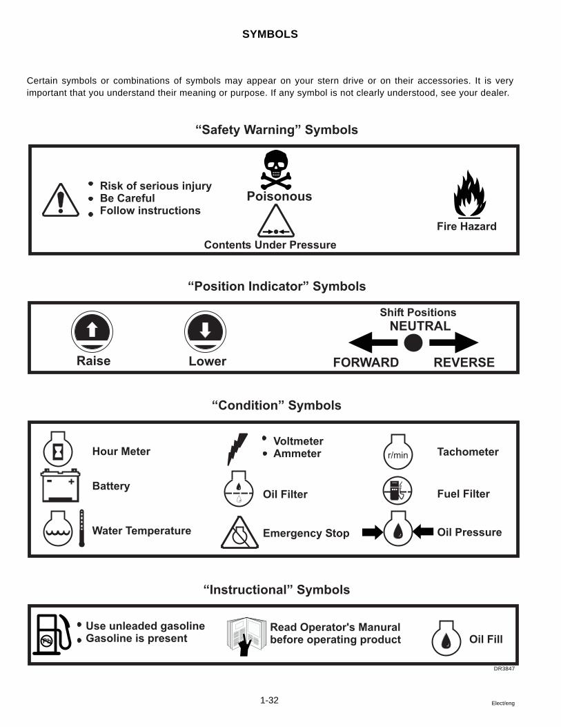
SYMBOLS
Certain symbols or combinations of symbols may appear on your stern drive or on their accessories. It is veryimportant that you understand their meaning or purpose. If any symbol is not clearly understood, see your dealer.
DR3847
“Safety Warning” Symbols
“Position Indicator” Symbols
“Condition” Symbols
“Instructional” Symbols
Poisonous
Fire Hazard
Risk of serious injuryBe CarefulFollow instructions
Contents Under Pressure
Raise Lower REVERSEFORWARD
Shift Positions
NEUTRAL
Hour Meter
Battery
Water Temperature
Oil Filter
Emergency Stop
VoltmeterAmmeter r/min
Oil Pressure
Fuel Filter
Tachometer
Oil FillRead Operator's Manuralbefore operating product
Use unleaded gasolineGasoline is presentPb
- +

1-33Elect/eng
tnioPecivreS tnioPecivreS tnioPecivreS tnioPecivreS tnioPecivreS sruoH52yrevE sruoH52yrevE sruoH52yrevE sruoH52yrevE sruoH52yrevEdeificepSsaro
sruoH05yrevE sruoH05yrevE sruoH05yrevE sruoH05yrevE sruoH05yrevEdeificepSsaro
snoitadnemmoceR snoitadnemmoceR snoitadnemmoceR snoitadnemmoceR snoitadnemmoceR
roterubraC .dedeensaroyllaunnA .MPReldidnaerutximelditsujdA.egaknilnaelC
gnitnuoM-rotserrAemalF .yllaunnakcehcdnanaelC .degamadfiecalpeR.tunnethgiT
retliFleuF yllaunnA .retlifleufecalpeR
pmuPleuFlacinahceM tnevtnerapsnartkcehCroleuffoecneserprofebut
.lio
.pmupleufgnikaelecalpeRgnitratsretfaskaelrofkcehC
.enigne
metsySleuF .yliadegakaelrofkcehC ecalpeR.snoitcennocnethgiTdeificepshtiw atnePovloV.stnenopmoc
knaTleuF .knatleufniretawrofkcehC htiwdellifknatpeeK.leufdednemmocer
sesoHleuFcillateM-noN ,ssenffitsevissecxerofkcehCyreveegakaelro/dnanoitaroireted
revehcihw,ylhtnomrosruoh05.tsrifsemoc
htiwyrassecensaecalpeR.stnenopmocdevorppa.C.Y.B.A
ecivreS ecivreS ecivreS ecivreS ecivreStnioP
sruoH52yrevE sruoH52yrevE sruoH52yrevE sruoH52yrevE sruoH52yrevEdeificepSsaro
sruoH05yrevE sruoH05yrevE sruoH05yrevE sruoH05yrevE sruoH05yrevEdeificepSsaro
snoitadnemmoceR snoitadnemmoceR snoitadnemmoceR snoitadnemmoceR snoitadnemmoceR
yrettaBleveletylortcelekcehC
ylhtnomsnoitcennocnethgiT
ytivargcificepsfiyrettabegrahceRerutarepmet022.1wolebsdaer
.detcerroc
metsySlacirtcelE .noitalusnidnasnoitcennockcehCecalperdna,snoitcennocesoolnethgiT
.gniriwdetaroireted
sdaeLnoisneThgiHpaCrotubirtsiDro/dna
ronoitaroireted,noisorrocrofkcehCnoylgunstiftsumstooB.gnicra
.slanimret
htiwecalper,degamadfIniatniaM.strapatnePovloVdeificeps
.troppusdnagnituorlanigiro
lioCnoitingIcitsalpniskcarcrognicrarofkcehC
.liocfonoitropatnePovloVdeificepshtiwecalpeR
.strap
sgulPkrapS.skcarcrofcimareckcehcyllaunnA
.pagdnanaelcro,ecalpeRdeificepshtiwecalper,degamadfI
lanigironiatniaM.strapatnePovloV.troppusdnagnituor
Periodic Maintenance Chart
Items marked Safety Warning are safety related service points to prevent mechanical failures, fire and explo-sion. Make sure the safety related service is performed at these points and at the intervals specified.
Electrical
Fuel
Safety Related

1-34 Elect/eng
General Torque Specifications
The following specifications are for nut and screw sizes not havingspecific torque recommendations.
seziSwercS.S.U seziSwercS.S.U seziSwercS.S.U seziSwercS.S.U seziSwercS.S.U .sbL.tF .sbL.tF .sbL.tF .sbL.tF .sbL.tF NNNNNmmmmm seziSdaerhTcirteM seziSdaerhTcirteM seziSdaerhTcirteM seziSdaerhTcirteM seziSdaerhTcirteM .sbL.tF .sbL.tF .sbL.tF .sbL.tF .sbL.tF NNNNNmmmmm
6.oN8.oN
01.oN21.oN02-4/1
81-61/561-8/341-61/7
...
...5,3-2
4-37-5
41-2152-0204-23
6,1-1,18,2-2,27,4-7,24,5-1,45,9-8,691-6143-7245-34
6-M8-M
01-M21-M41-M
9-612-4104-8217-05411-08
21-882-9145-8369-86
551-801

2-1Elect/eng
Section 2Cranking System
Table of Contents
2Cranking System Operation .............................................................. 2-2Cranking System Problems ............................................................... 2-9Starter Motor
Bench Test ....................................................................................... 2-5Replacement .................................................................................... 2-6Specifications ................................................................................ 2-10Test Procedures .............................................................................. 2-2
Wiring Diagrams, Cranking Circuit ................................................... 2-7
Safety Warnings
Before working on any part of the electrical system, read the Safetysection at the end of this manual.
The original mounting, support and routing of electrical systemparts conform with U.S. Coast Guard requirements. It is importantto maintain the original mounting, support and routing after ser-vicing the electrical system to prevent possible fire and explosionin boat’s engine compartment.
Do not substitute automotive parts. Volvo Penta marine compo-nents meet U.S. Coast Guard regulations for external ignition proofoperation and marine use. Volvo Penta marine components arespecially designed not to cause ignition of fuel vapors in the bilgeor engine compartment. The use of automotive parts can result infire and explosion.
Sealants, Lubricants and Adhesives
Black neoprene dip

2-2 Elect/eng
Cranking System Operation
The cranking system consists of a 12 volt starter motor, solenoid(s),ignition switch, neutral start switch, 50 amp circuit breaker, 20 ampfuse and wiring to complete the circuit with the battery.
Any remote control box used with the stern drives coveredin this manual must have a neutral start switch which preventsoperation of the starter if the control handle is not in the neutralposition. All Volvo Penta remote controls meet this requirement.
Stern drive starters employ a solenoid and lever to close the batterycircuit and engage the starter pinion with the flywheel ring gear. Whenthe key switch is turned to START position, an assist solenoid ener-gizes the starter solenoid which closes the battery circuit and throughleverage engages the starter pinion with the flywheel ring gear. Whenthe key switch is released, the solenoids are de-energized, springsopen the battery circuit, and the over-running clutch disengages thestarter pinion.
Starter Motor Test Procedures
Special Tools Required: Battery Hydrometer, Voltmeter, Ammeter, Ta-chometer, Jumper Wire
Do not substitute an automotive type starter. The Volvo Pentastarter motor meets U.S. Coast Guard regulations for external ig-nition proof operation and marine use. The Volvo Penta starter isspecially designed not to cause ignition of fuel vapors in the bilgeor engine compartment. The use of automotive type starters canresult in fire and explosion.
Inspection Procedure
No periodic lubrication of the starter motor or solenoid is required.Starter motor action is indicative, to some extent, of the starter motorcondition. A starter motor which responds readily and cranks the en-gine at normal speed when the control circuit is closed is usually ingood condition.
Check the starter motor and solenoid switch attaching bolts to makesure these units are solidly mounted; both the starter and solenoiduse their mounting for a ground path. Inspect and manually check allwiring connections in the starter motor circuit. Make sure these con-nections in the starter motor and control circuits are clean and tight. Itis advisable to test the cranking circuit to ensure that excessive resis-tance does not exist. See Test Procedure.
Safety Related

2-3Elect/eng
Test Procedure With Starter Installed
The voltage across the starting motor and switch, while cranking theengine, gives a good indication of any excessive resistance.
All remote control boxes used with Volvo Penta stern drivesmust have a neutral start switch to prevent operation of the starterif the shift lever is not in the neutral position. Engine must be atnormal operating temperature when test is made.
1. Inspect the battery and cables to make sure that battery has amplecapacity for cranking and ignition. Battery must be fully charged.
2. To crank the engine without firing:
Ensure ignition switch is off when disconnecting primarywires. Failure to do so may result in sparking that can ignite fuelvapors in engine compartment or bilge, and may result in fire orexplosion.
• All Models Except 5.0 GL and 5.7 GS: Turn off ignitionswitch, and disconnect both 2-wire connectors at igni-tion coil.
• 5.0 GL and 5.7 GS: Turn off ignition switch, disconnectpurple leads from ignition coil.
1 3. Connect the voltmeter POSITIVE (+) lead to the motor terminalA on the solenoid switch; connect the voltmeter NEGATIVE (-) lead toground B on starter.
4. Turn the ignition switch on, crank engine and take voltmeter readingas quickly as possible. If starter motor turns engine at normal crankingspeed with voltmeter reading nine or more volts, the motor and switchare satisfactory. If the cranking speed is below normal and the voltme-ter reading is lower than 9 volts, check for defective battery, corrodedbattery terminals, or corroded solenoid.
Do not operate starter motor for more than 10 seconds at a timewithout pausing to allow motor to cool for at least two minutes; other-wise, overheating and damage to the motor may result.
Safety Related
DR3199
1

2-4 Elect/eng
Solenoid Contacts Test
If the starter motor turns the engine at a low rate of speed and thevoltmeter reads less than 9 volts, test the solenoid switch contacts asfollows:
1 1. With the voltmeter switch turned to any scale above 12 volts,connect the voltmeter NEGATIVE (-) lead to the motor terminal A ofthe solenoid switch and connect the POSITIVE (+) lead to the batteryterminal B of the solenoid switch.
2. Turn the ignition switch on and crank the engine. Immediately turnvoltmeter switch to low scale and take reading as quickly as possible,then turn switch back to higher scale and stop the motor.
The voltmeter will read 1/10 volt or less if solenoid switch contacts aresatisfactory. If voltmeter reads more than 1/10 volt, solenoid switchshould be repaired or replaced.
Solenoid Amperage Test
An amperage test of the solenoid switch will determine two things:
• Current draw of both windings in parallel.
• Current draw of hold-in winding alone.
2 1. Remove screw from solenoid motor terminal C and bend fieldleads slightly until clear of terminal. Ground motor terminal of solenoidwith a heavy jumper wire D .
2 2. Connect a 12 volt battery, a variable resistance E (such as acarbon pile), and an ammeter F of 100 amperes capacity in serieswith the solenoid “S” terminal G . Connect a heavy jumper wire H
from starter to ground post of battery.
2 3. Connect a voltmeter I between the base of the solenoid andthe small solenoid “S” terminal.
4. Slowly adjust resistance until voltmeter reads 10 volts and note am-meter reading. This shows current draw of both windings in parallel,and should be 47 to 55 amperes at 10 volts, with solenoid at roomtemperature.
5. Remove the jumper wire from the solenoid motor terminal and read-just resistance until voltmeter reads 10 volts, then note ammeter read-ing. This shows current draw of hold-in winding alone and should be15 to 20 amperes at 10 volts with solenoid at room temperature.
DR3203
DR3195
2
1

2-5Elect/eng
6. If the solenoid windings do not test within the specifications given,the solenoid switch assembly should be replaced.
Starter Motor Bench Test
3 To obtain full performance data on a starter motor, or to determinethe cause of abnormal operation, the motor should be removed fromthe engine and submitted to a no-load test with equipment designed forsuch tests. In a no-load test the starter motor is connected in serieswith a 12 volt battery J and an ammeter K capable of reading severalhundred amperes. A variable resistor L is connected between the am-meter and the solenoid battery terminal. Attach a voltmeter M betweenthe solenoid BAT terminal and motor ground N . Activate the motor byattaching a jumper wire O between the solenoid’s BAT and S (starter)terminals. A tachometer or RPM indicator is used to indicate armatureRPM. Starter motor specifications will be found at the end of this sec-tion.
Compare the results of the test with the chart below. This will indicatewhat should be looked for when the motor is overhauled.
DR3200
3
Test Result Probable Cause
1. Current draw and no-loadspeed within specifications
Normal condition for starting motor.
2. Low free speed and highcurrent draw
Too much friction - namely tight, dirty or worn bearings, bent armature shaft, or loosepole shoe screws allowing armature to drag. Shorted armature. Check afterdisassembly on growler. Grounded armature or fields. Check further after disassembly.
3. Fails to operate with highcurrent draw
Direct ground in terminal or fields. "Frozen" bearings. Should be noticed by turningarmature by hand.
4. Fails to operate with nocurrent draw
Open field circuit. Check after disassembly by inspectig internal connections andtracing circuit with a test lamp.Open armature coils. Inspect for badly burned bars after disassembly.Broken brush spring, worn brushes or high insulation between commutator bars thuspreventing good brush to commutator contact.
5. Low no-load speed and lowcurrent draw
High internal resistance due to poor connections, defective leads or dirty commutator.(Also, causes listed under 4, above.)
6. High free speed and highcurrent draw
Shorted field coils. If shorted field coils are suspected, replace with new coils andcheck for improved performance.

2-6 Elect/eng
Starter Motor Replacement
Removal
Do not substitute an automotive type starter. The Volvo Pentastarter motor meets U.S. Coast Guard regulations for external ig-nition proof operation and marine use. The Volvo Penta starter isspecially designed not to cause ignition of fuel vapors in the bilgeor engine compartment. The use of automotive type starters canresult in fire and explosion.
1. Disconnect the battery ground cable at battery and dis-connect all wires at solenoid terminals to prevent sparks in en-gine compartment.
1 2 2. Cut the strap A holding bell housing drain hose, ifequipped, to solenoid. Remove nut from starter support bracket. Re-move ring gear guard B from front of flywheel housing. Take out startermounting screws and remove the starter assembly.
Installation
1. To reinstall, position the starter assembly on the engine and startthe mounting hardware.
2. Snug hardware while holding the starter squarely against its mount-ing surface. Tighten the screws to 30-36 ft. lb. (41-49 N•m). Install ringgear guard and tighten screws to 5-7 ft. lb. (7-9 N•m).
3. Connect wires to solenoid and apply black neoprene dip to termi-nals to prevent corrosion.
4. Connect battery ground cable at battery. Attach bell housing drainhose, if equipped, to solenoid with a tie strap.
14704
6715
A
1
2

2-7Elect/eng
3.0 GS Models4.3 GL Models5.0 GL Models5.7 GS Models
Cranking Circuit
1 Black2 Red3 Yellow/Red4 Starter Relay5 Red/Purple6 20 Amp Fuse7 40 Amp Fuse
DRC7513
7 6
R40
47

2-8 Elect/eng
Cranking Circuit4.3 Gi Models
5.0 Gi5.7 GSi
7.4 Gi & GSi Models8.2 GSi Models
DRC7518
7 6
R40
47
1 Black2 Red3 Yellow/Red4 Starter Relay5 Red/Purple6 20 Amp Fuse7 40 Amp Fuse

2-9Elect/eng
Cranking System Problems
Starter turns engine slowly . Check:
• battery water level and specific gravity• for loose and corroded connections• engine and drive unit for binding• starter armature, brushes, field coils, or bearings
Starter turns intermittently . Check:
• starter motor - complete tear-down• connection at ignition switch• starter solenoid
Starter doesn’t turn - solenoid clicks. Check:
• battery and connections• starter solenoid• engine, transom bracket and vertical drive for seizure,
or debris• starter armature, brushes, or field coils
Starter doesn’t turn - solenoid doesn’t click. Check:
• remote control in start position, shift into neutral• battery and connections• starter solenoid• key switch and wiring circuit 20 amp fuse• 50 amp circuit breaker
Starter remains engaged and runs with engine. Check:
• shorted ignition switch• starter motor - complete tear-down• defective electric fuel pump “Orange” lead diode - 4.3
GL, GS, 5.0 GL and 5.7 GS models only

2-10 Elect/eng
Starter Motor Specifications
Do not substitute automotive parts. Volvo Penta marine com-ponents meet U.S. Coast Guard regulations for external ignitionproof operation and marine use. Volvo Penta marine componentsare specially designed not to cause ignition of fuel vapors in thebilge or engine compartment. The use of automotive parts canresult in fire and explosion.
Motor Free Speed At 11.5 Volts (between 3-5 seconds)Current - 64-95 amps
Speed - 2825-3275 RPM
Safety Related

3-1Elect/eng
Section 3Charging System
Table of Contents
3
Sealants, Lubricants and Adhesives
Black neoprene dip
Alternator ServiceAssembly ....................................................................................... 3-15Belt Tension ..................................................................................... 3-4Disassembly .................................................................................. 3-10Internal Diagram ............................................................................ 3-20Replacement .................................................................................... 3-3Specifications ................................................................................ 3-21Testing Rectifier ............................................................................ 3-13
Charging System Problems ............................................................. 3-19Circuit Diagrams ............................................................................... 3-17Description .......................................................................................... 3-2Troubleshooting
Alternator ......................................................................................... 3-5Chart ................................................................................................. 3-8Wire Harness Tests .......................................................................... 3-6
Safety Warnings
Before working on any part of the electrical system, read the Safetysection at the end of this manual.
The original mounting, support and routing of electrical system partsconform with U.S. Coast Guard requirements. It is important to main-tain the original mounting, support and routing after servicing theelectrical system to prevent possible fire and explosion in boat’sengine compartment.
Do not substitute automotive parts. Volvo Penta marine componentsmeet U.S. Coast Guard regulations for external ignition proof opera-tion and marine use. Volvo Penta marine components are speciallydesigned not to cause ignition of fuel vapors in the bilge or enginecompartment. The use of automotive parts can result in fire andexplosion.

3-2 Elect/eng
Description
Stator
1 There are three independent windings connected together in thestator, in which three-phase alternating current is produced. There aretwo types of stator windings used in the alternator: the “Delta” - connec-tion A and the “Y” - connection B .
Rotor
2 The rotor core and coil assembly includes; a rotor shaft, two sliprings, two rotor poles and a coil assembly. The rotor shaft is supportedat each end by bearings. The slip rings, core and coil assembly arepress fitted to the shaft with a rotor pole enveloping each end of thecoil. Protected slip-type field windings are bonded with epoxy resin andanchored to resist damage by vibration from sharp acceleration.
The rotor assembly is balanced to provide smooth, efficient operationthroughout normal speed range. The slip rings are made of copper, andthus rustproof, keeping good electrical contact. The rotor core and coilassembly turns inside the stator core and coil assembly with a verynarrow air gap between the two assemblies. This narrow clearancepermits maximum magnetic power.
Rectifier
3 The rectifier, with six silicon diodes, is located between the statorand the inside surface of the rear bracket.
4 Three of the six diodes are positive, and are located in an insu-lated heat sink. The current induced in the stator coil flows into thepositive diodes and comes out the “B” terminal. Three other negativediodes are located in the negative heat sink that is grounded. The sixdiodes act together to change the alternating current produced in thealternator into direct current.
Regulator
5 The voltage regulator assembly contains the voltage regulator,brush holder and the brushes.
DRC6720
45453
45438
45439
45448
1
2
3
4
5

3-3Elect/eng
Alternator Replacement
Carbureted Models Only
Removal
To ensure proper operation and to protect the alternator and regulator, thefollowing steps should be observed during removal and installation.
Do not substitute automotive parts. Volvo Penta marine compo-nents meet U.S. Coast Guard regulations for external ignition proofoperation and marine use. Volvo Penta marine components are spe-cially designed not to cause ignition of fuel vapors in the bilge orengine compartment. The use of automotive parts can result in fireand explosion.
1. Disconnect the battery ground cable at battery.
6 2. Remove alternator adjusting bolt C from brace. Loosen pivot boltand nut D .
3. Push alternator towards engine and remove alternator belt.
7 4. Disconnect all leads from the alternator.
8 5. Remove alternator pivot bolt and nut D . Remove the alternator.
Installation
8 1. Position alternator in bracket and loosely install the pivot bolt andnut D .
9 2. Connect purple lead E to “EXC” terminal. Connect black lead F
to “E” terminal. Tighten nuts securely and coat both terminals with blackneoprene dip.
10 3. Connect heavy gauge orange lead G to “B” terminal andorange jumper lead H to “S” terminal. Tighten nuts securely. Slide rub-ber boot up lead and cover terminal.
10 4. Carbureted Models Only: Connect purple/white lead to“P” terminal. Tighten nut securely. Slide rubber boot up lead and coverterminal.
Safety Related
49475
49480
49483
49481
49482
8
6
7
9
10

3-4 Elect/eng
1 5. 4.3 GL, 5.0 GL, 5.7 GS and DPX models only: Connect theelectric fuel pump lead to the “L2” terminal. Coat the ground terminalwith black neoprene dip.
2 5. Pivot alternator towards the engine and place the belt onto thepulley. Attach the alternator brace to the alternator with screw A . Fol-low the procedure for “Alternator Belt Tension” in this section. Correctlytension the belt and tighten all mounting bolts B to 26-30 ft. lb. (35-41N•m).
7. Connect battery cables.
Alternator Belt Tension
• Carbureted V6 and V8 Models 41 Crankshaft Pulley2 Circulating Pump Pulley3 Alternator Pulley4 Belt Tension Check Point
With engine stopped, check belt tension half way between the crank-shaft and the alternator using one of the following methods:
5 Use belt tension gauge to set tension to 75 ± 10 lb. (33.6 ±
44.5 N).
6 Use light thumb pressure and check for 1/4 in. (6.4 mm)
belt deflection.
If belt is too tight, excessive belt and bearing wear can occur. If it’s tooloose, slippage can occur, resulting in belt wear; and poor circulatingpump, alternator, or power steering operation. Tension of a new beltshould be checked after 10 hours of service and every 50 hours there-after.
3.0GS and Fuel Injected Models except DPX.
7 The serpentine belt tension is set automaticlly by the belt tensioner.No adjustment is needed.
49480 45382 45373
DRC7451
47507
47508
3
4
5
6
7
1 2

3-5Elect/eng
1. Loosen alternator mounting bolts and nuts, and pivot alternator awayfrom engine to increase belt tension.
8 9 2. While maintaining pressure on alternator, retighten top bolt,bottom bolt and nut. Recheck belt tension.
The belts used for the alternator, circulating pump, and powersteering pump are heavy-duty. Do NOT replace with automotive belts.
When adjusting alternator belt, do not overtightens The alterna-tor may be damaged.
Troubleshooting the Alternator
Belt Tension
6 7 Check the alternator belt for correct tension.
Alternator Output Test
Before beginning charging system checks, test the alternator output toverify that a charging problem exists.
10 1. Disconnect orange lead D from “B” terminal at back of alterna-tor and connect an ammeter E in series.
10 2. Attach a voltmeter F to the “B” terminal G and an engine ground.
3. Connect a carbon pile or Stevens LB-85 Load Bank across the bat-tery.
4. Start and run the engine. The amperage and voltage output readingsshould be as follows when the carbon pile is adjusted to obtain maxi-mum output:
650 RPM - 20 amps min.
1500 RPM - 53 amps min.
2000+ RPM - 56 amps min.
Regulated Voltage Range: 14.0 - 14.7 volts
49476
49477
DRC7602
10
8
9

3-6 Elect/eng
The output test results will fall into one of these categories; overcharg-ing, undercharging or no charge at all.
If battery overcharge is indicated by excessive water use, ammeter orvoltmeter showing consistent charge, or alternator output exceeding15.0 volts (no load) with engine idling, check orange “S” lead voltage.Low volts, or no volts, will cause overcharging. If orange “S” lead volt-age is okay, voltage regulator is shorted and must be replaced.
If battery undercharge (or no charge) is indicated, perform the follow-ing tests in the order shown.
Alternator Wire Harness Tests
For the battery to receive sufficient charging current, and the alternatorto supply the correct amount, three wires must carry battery voltage;the orange output (“B”) lead, orange jumper (“S”) sense lead and thepurple excite (“EXC”) lead.
Check No. 1: Testing Battery Charging Circuit
1. Slide the protective rubber boot off the “B” terminal.
1 2. Connect the voltmeter positive lead to the orange lead A , andnegative lead to an engine ground B . With the key switch off, the volt-meter should show a reading nearly equal to battery voltage.
Test Results:
a. Circuit Okay - voltage reading is within a few tenths of bat-tery voltage. Go on to Check No. 2.
b. Excessive Resistance - one or more volts less than batteryvoltage (example: 10.2 volts versus 11.8 volts).
c. Open Circuit - a voltmeter reading of zero.
If circuit is open or resistance is excessive, disconnect orange lead atalternator. With an ohmmeter, check alternator output circuit betweenalternator and battery. Correct any problems, then conduct alternatoroutput test again. If output reading is still not as specified, go on tofollowing test.
DRC7601
1

3-7Elect/eng
Check No. 2: Testing Ignition Circuit
2 1. Connect a voltmeter to the “EXC” lead C at back of alternatorand an engine ground B .
2 2. With battery connected and key switch E on, the voltmeter read-ing should be within a few tenths of battery voltage.
Test Results:
a. Circuit Okay - voltage reading is within a few tenths of batteryvoltage. Go on to Check No. 3.
b. Excessive Resistance - one or more volts less than batteryvoltage (example: 10.2 volts versus 11.8 volts).
c. Open Circuit - a voltmeter reading of zero.
d. Grounded Circuit - a reading of zero accompanied by a blownfuse or circuit breaker each time key switch is turned on.
Results were conditions “b” or “c”: disconnect the purple lead fromback of alternator, then use an ohmmeter to check wire continuity backto key switch. Correct any problems, then conduct alternator output testagain.
3 Results were condition “d”: disconnect the purple lead from backof alternator and repeat voltage check, Steps 1 and 2 above. If fuse orcircuit breaker no longer blows, circuit is grounding through alternator;replace alternator. Fuse or circuit breaker continues to blow, check wir-ing back to key switch to find cause. Correct any problems, then conductalternator output test again.
If the tests show the engine wiring, battery or accessories are not atfault, make additional running tests on the alternator, Check No. 3.
Check No. 3: Testing Excite/Sense Circuit
1. Unscrew protective cap on “L2” terminal. Retain cap for reuse.
4 2. With key switch E on, but engine not running, check for 1.0-2.0volts at the “L2” terminal D .
3. If “L2” terminal voltage is not as specified, replace voltage regulator.
If alternator still fails to produce the specified voltage/amperage afterinstallation of a new regulator, the alternator will have to be disassembledin order to test internal components.
DRC7600
DRC7599
DRC7598
2
3
4

3-8 Elect/eng
Alternator Troubleshooting Chart
Troubleshooting the charging system may involve any one or more of the components in the system: the alternator(including voltage regulator), the battery, key switch, and wiring connecting these components into a circuit.
The following troubleshooting chart categorizes trouble and remedies.
elbuorT elbuorT elbuorT elbuorT elbuorT elbuorTfoecalP elbuorTfoecalP elbuorTfoecalP elbuorTfoecalP elbuorTfoecalP esuaCelbaborP esuaCelbaborP esuaCelbaborP esuaCelbaborP esuaCelbaborP ydemeR ydemeR ydemeR ydemeR ydemeR
yrettaB-rednU
gnigrahC
tleBnaF gnippilstlebnaF tlebfonoisnetehttsujdaeR
rotanretlA detcennocsidrodednuorgliocrotatS.1
detcennocsidliocrotoR.2
tcatnoctneiciffusnignirpilsdnahsurB.3
detarepoyltnettimretniedoiD.4
erutcnuproticapaC.5
fiylbmessarotatsecalperroriapeRyrassecen
ecalpeR
otsredloh(,dewenerebotsehsurbnroWdehsilopgnirpils)denaelceb
ylbmessareifitcerecalpeR
roticapacecalpeR
yrettaB etylortceledabrohguonetoN.1
)tiucrictrohs(etalpdetafluS.2
dedorrocoteudtcatnoctneiciffusnI.3lanimret
ytivargcificepsgnirusaemer,ylppuS
yrettabegnahC
nethgitdnanaelC

3-9Elect/eng
Alternator Troubleshooting Chart (Cont.)
elbuorT elbuorT elbuorT elbuorT elbuorT elbuorTfoecalP elbuorTfoecalP elbuorTfoecalP elbuorTfoecalP elbuorTfoecalP esuaCelbaborP esuaCelbaborP esuaCelbaborP esuaCelbaborP esuaCelbaborP ydemeR ydemeR ydemeR ydemeR ydemeR
-rednUyrettaBgnigrahC
gniriW tneiciffusnironoitcennocsiDhctiws-yekneewtebtcatnoclanimret"cxE"rotalugerdna
riapeR
eldeeNretemmAelbatsnU
tleBnaF tlebnafesooL noisnettlebtsujdaeR
hctiwSyeK tcatnoctneiciffusnihctiwsyeK hctiwsyekegnahC
gniriW tsomla,esooltniopnoitcennoCseriwdetcennocsid
riaper,nethgiT
morfesioNlamronbArotanretlA
rotanretlA sgniraebroirefnI.1
erutcnupedoiD.2
rodednuoorgliocrotatS.3detrohsreyal
sgniraebegnahC
ylbmessareifitcerecalpeR
ylbmessarotatsecalpeR
gnigrahCdetleMesuFtiucriC
gniriW detrohslanimret"B" riapeR
rotanretlA evitagendnaedisevitisoP.1detrohsedoidedis
erutcnuproticapaC.2
ylbmessareifitcerecalpeR
roticapacecalpeR
rotalugeR egrahcrevO rotalugerecalpeRylbmessa
yrettaB detcennocsimyrettaB ylreporptcennoC

3-10 Elect/eng
5
Alternator Disassembly
To prevent possible fire and explosion, do not substitute au-tomotive parts for this alternator or its internal components. Theseparts and assemblies have been specifically designed not to causeignition of fuel vapors in the bilge.
Regulator/Brush Holder Removal
1 1. Remove protective cap A from “L2” terminal. Remove twoflange nuts B and one screw C securing the regulator cover. Re-move cover.
2 2. Remove two screws D securing the regulator/brush holderassembly. Remove assembly.
3 3. Remove the nut holding the capacitor. Remove capacitor.
4 4. Remove three insulators from the “L2,” “P,” and “B” terminals.
5 5. Remove the four thru-bolts securing alternator housing.
Safety Related
45383
45384
45385
45386
45387
1
2
4
5
3

3-11Elect/eng
Rotor Removal
6 1. Set alternator with pulley side down. Insert a screwdriver oneach side of the housing. Pry from under the stator using any two lowerslots. Do not pry on coil wires.
7 2. Remove the stator and rear housing from the rotor assembly.
8 9 3. Use a soft jaw vise to hold the rotor armature. Remove thepulley nut E , washer F , pulley G , tall spacer H and fan I from therotor shaft.
10 4. Using a plastic hammer, tap the top of the rotor shaft while liftingup on the front housing. Remove short spacer J and front bracket K .
45389
45390
45391
45392
45397
6
7
8
9
10

3-12 Elect/eng
Bearing Removal
1 Remove the three screws A and retainer B from front housing.Support bracket in a press on the inside machined surface. Press bear-ing out from the bracket.
Stator Removal
2 Unsolder the stator leads. Hold the rectifier lead with long nosepliers to protect rectifier from the heat. Remove the stator.
Rectifier Removal
3 Remove the screw securing the rectifier to the back housing. Re-move rectifier.
Testing Stator
The stator consists of three separate windings terminating in a deltatype connection. It produces alternating current for charging the bat-tery and operating electrical accessories. The windings must be checkedfor grounds and open circuits with an ohmmeter. Any stators with dis-colored windings should be replaced.
Open Circuit Check
1. Resistance through the stator is very low, so set an ohmmeter on thelow ohm scale.
4 2. Connect the leads to terminals C and D and check for ap-proximately 0.2 ohm resistance. Repeat this check using terminals C
and E , then terminals D and E . The resistance values of all threechecks must be the same. If not, replace the stator.
Ground Check
5 1. Set the ohmmeter on the high ohm scale. Connect the leadsbetween one terminal and the stator frame. The meter must show nocontinuity (infinity).
2. Repeat this check with the remaining two terminals. If any readingshows continuity, the stator is grounded and must be replaced.
45396
45395
45393
45398
45399
1
2
3
5
4

3-13Elect/eng
Testing Rotor Assembly
The rotor assembly requires two tests; one for shorts and open circuits,the other for grounds. Conduct both checks with an ohmmeter.
Clean slip ring surfaces with a fine crocus cloth and wipe offdust. This will ensure accurate ohmmeter readings.
Open/Short Circuit Check
1. Set the ohmmeter to the low scale.
6 2. Touch one ohmmeter lead to each slip ring. The meter readingshould be approximately 4.1 to 4.7 ohms at room temperature. A lowerreading indicates shorted windings. A higher reading shows excessiveresistance. An infinity reading means an open circuit. Replace the rotorif it doesn’t have the specified resistance.
Ground Check
1. Set the ohmmeter to the high scale.
7 2. Touch one meter lead to a slip ring and the other to the rotorbody. The only acceptable reading is infinity. Any continuity reading meansthe rotor assembly is grounded and must be replaced.
Testing Rectifier
The rectifier contains nine diodes. The rectifier converts stator alternat-ing current into direct current as it leaves the alternator. Tests must bemade with an ohmmeter to check continuity of all nine diodes in bothdirections of polarity.
Checking Positive Diodes
8 1. Test the positive diode by touching the positive ohmmeter probeto the terminal of each diode and touching the negative ohmmeter probeto the heat sink.
2. All the diodes should indicate continuity. If a diode indicates no conti-nuity, that diode is open, replace the rectifier assembly.
3. Reverse the probes to check the diode in the other direction. All thediodes should indicate no continuity. If it indicates continuity, that diodeis shorted, replace the rectifier assembly.
45400
45401
45449
6
7
8

3-14 Elect/eng
Checking Negative Diodes
1 1. Test the negative diode by touching the positive ohmmeter probeto the heat sink and the negative ohmmeter probe to the terminal ofeach diode.
2. All of the diodes should indicate continuity. If a diode indicates nocontinuity, that diode is open, replace the rectifier assembly.
3. Reverse the ohmmeter probes to check the diode in the other direc-tion. All of the diodes should indicate no continuity. If diode indicatescontinuity, that diode is shorted, replace the rectifier assembly.
Checking The Diode Trio
2 1. Test the diode by touching the positive ohmmeter probe to oneend of the diode and the negative ohmmeter probe to the opposite sideof the diode. Then reverse the probes to check the diode in the otherdirection.
2. The meter must show continuity only in one direction and a highresistance reading in the other.
3. Repeat this test on each of the two remaining diode terminals. Testresults must show a continuity reading in the same direction for all threediodes, and a high resistance reading in the opposite direction. If anydiode fails a test, replace the rectifier assembly.
Checking Brush and Brush Holder
3 1. Check the exposed brush length A . Minimum exposed lengthshould be 0.197 in. (5 mm).
2. The contact between the brush and a holder must be smooth. Theinsulation between the holder and bracket should be checked to makesure there is no electrical conduction.
3. Spring pressure range should be between 8.8 - 12.3 oz. (250 g - 350g) when spring length is 0.512 in. (13 mm). If tension is low, the lower-ing motion of the spring will be stiff and cause inadequacy of contactwith the slip ring. If pressure is high, wear from friction increases.
45451
45452
45410
1
2
3

3-15Elect/eng
Testing Capacitor
4 The capacitor is held to the alternator rear cover by a single screw.Use an appropriate capacitor tester and follow the manufacturer’s in-structions. The capacitor capacity should be 0.5 - 0.1 microfarad.
Voltage Regulator
There are no volt, ohm, or amperage tests for the voltage regulator be-cause it’s a solid-state, transistorized component. If all other alternatorcomponents test okay, replace the regulator.
Alternator Assembly
Rectifier and Stator Installation
5 1. Install rectifier into the alternator back housing. Secure therectifier with screw. Tighten securely.
6 2. Install stator into the front housing. Solder the three leads to eachdiode terminal.
Front Housing Assembly
7 1. Press bearing into front alternator bracket until it seats. Attachretainer to the inside of the bracket with three screws. Tighten securely.
8 2. Place rotor in a soft jaw vise. Install front housing over rotorshaft. Place the short spacer B on the shaft.
9 3. Place fan C onto the shaft with blades facing down. Place tallspacer D on the shaft.
10 4. Install pulley E , washer and pulley nut F onto the shaft. Tightennut to 47 ft. lb. (63 N•m).
45444 45411 45394
45412
45403
45404
45405
4 5 6
7
10
9
8

3-16 Elect/eng
Rotor Installation
1 1. Position stator with three screws A at the top and the pivotpoint B at the bottom. Align the four thru-bolt holes and tighten boltsC securely.
2 2. Install three insulators on the “L2”, “P” and “B” terminals.
3 3. Install capacitor D and secure with nut E . Attach capacitorwire to “B” terminal and tighten securely. Place nut on “P” terminal andtighten securely.
Regulator/Brush Holder Installation
4 5 1. Inspect seal for wear or damage. Place the seal on theregulator/brush holder assembly.
5 2. Push in brushes on the regulator/brush holder assembly andtemporarily lock in place with a pin or wire F inserted through accesshole in the brush holder.
6 3. Place regulator/brush holder onto the back alternator housing.Secure the regulator/brush holder assembly with two screws G andtighten securely. Seat the seal around the end of the housing H . Attachconducting strap I to terminal “L2”.
6 4. Remove the temporary holding pin F to release the brushes.Spin the alternator to be sure it moves freely.
7 5. Place cover over regulator/brush holder assembly and tightenthe two flange nuts J to 51 in. lbs. (5,8 N•m) and one screw K to 30 in.lbs. (3.4 N•m).
45406 45473 45474
45407
45475
45476
45477
1 2 3
4
5
6
7

3-17Elect/eng
Charging Circuit Diagram3.0 GS Models
4.3 GL and GS Models5.0 GL Models5.7 GS Models
1 Black2 Red3 Purple/White4 Red/Purple5 20 Amp Fuse6 Purple7 Carburetor Choke Coil8 Orange
DRC7517
M
MS
C A
B
B+
L2
P
EXC SE
+-
6
6 5
8
7
4
4
41
1
4
2
2
65
65
R
40
31

3-18 Elect/eng
Charging Circuit Diagram4.3 Gi Models5.0 Gi Models
5.7 GSi Models7.4 Gi, GSi Models
8.2 GSi Models
DRC7520
M
MS
C A
B
B+
L2
P
EXC SE
+-
6
6 5
84
4
41
1
4
2
2
65
65
R
40
1 Black2 Red3 Purple/White4 Red/Purple5 20 Amp Fuse6 Purple7 Orange

3-19Elect/eng
Charging System Problems
Battery . Check:
• Proper Cold Cranking Amps rating• All wiring and connections• Specific gravity• Water, add and recharge• Make load test
Overcharge. Check:
• Regulator• Loose connections• Battery
Undercharge. Check:
• Belt tension• Regulator• Tarnished slip rings• Internal alternator components
No charge. Check:
• Alternator ground• Belt tension• 20 amp fuse and 50/60 amp circuit breaker• All wiring and connections• Regulator• Tarnished slip rings• Internal alternator components
Ignition Misfire. Check:
• Alternator ground
Inoperable Electric Fuel Pump. Check:
• 4.3 GL, GS, 5.0 GL and 5.7 GS models only - voltage at“L2” terminal
Inoperable Electric Choke. Check:
• All carbureted models - voltage at “P” terminal

3-20 Elect/eng
Alternator Internal Diagram
1 Regulator2 Rotor (field)3 Stator4 Rectifier5 Diode Trio6 Capacitor
DRC6719
EXC
S
E
L2
0.5MF
BP
KEYLOAD
F
(REG.)(REG.) 1
2
3
4
56

3-21Elect/eng
Specifications
Alternator - 65 Amp
Minimum Engine RPM for Alternator Output ................................................................................................. 400 RPMRegulated voltage range ............................................................................................................................. 14.0 - 14.7Amperage output ....................................................................................................................................................... 65Regulator ........................................................................................................................................ Internal, solid stateBelt tension .......................................................................................................... 1/4-1/2 in. give with finger pressureOutput tests: ................................................................................. Load battery to obtain maximum alternator output At 650 engine RPM ............................................................................................................ 20 amps approximately At 1500 engine RPM ........................................................................................................................... 53 amps min. At 2000+ engine RPM ......................................................................................................................... 56 amps min.“L2” terminal voltage (engine running) ...............................................................................................13.0 - 14.0 volts“P” terminal voltage (engine running) ..................................................................................................... 6.5 - 7.5 voltsCapacitor capacity...................................................................................................................... 0.5 ± 0.1 microfarads


4-1Elect/eng
Section 4Trim/Tilt Electrical System
All Models
Table of Contents
Relay Ohmmeter Tests ........................................................................ 4-7Trim Sending Unit
Adjustment Procedure .................................................................... 4-6Test Procedure ................................................................................ 4-6
Specifications ..................................................................................... 4-8Trim/Tilt
Operation ......................................................................................... 4-2Switch .............................................................................................. 4-3
Troubleshooting .................................................................................. 4-4Trim/Tilt Circuit Wiring Diagram ........................................................ 4-9
Safety Warnings
Before working on any part of the electrical system, read the Safetysection at the end of this manual.
The original mounting, support and routing of electrical system partsconform with U.S. Coast Guard requirements. It is important to main-tain the original mounting, support and routing after servicing theelectrical system to prevent possible fire and explosion in boat’sengine compartment.
Do not substitute automotive parts. Volvo Penta marine componentsmeet U.S. Coast Guard regulations for external ignition proof opera-tion and marine use. Volvo Penta marine components are speciallydesigned not to cause ignition of fuel vapors in the bilge or enginecompartment. The use of automotive parts can result in fire andexplosion.
4

4-2 Elect/eng
Trim/Tilt Operation
Stern drive models covered in this manual are equipped with powertrim/tilt as standard equipment. The purpose of the trim/tilt system is toenable the operator to change the angle of the vertical drive from thehelm. Changing the angle of the vertical drive in relation to the boatbottom is called “trimming.” Trimming provides the following benefits:
• Improves acceleration onto plane
• Maintains boat on plane at reduced throttle settings
• Increases fuel economy
• Provides smoother and/or drier ride in choppy water con-ditions
• Increases top speed
The trim/tilt switch is located on the remote control handle or on theboat’s dashboard. The trim/tilt switch changes the direction of move-ment of the boat’s bow. The trim/tilt gauge located on the dash showsthe corresponding bow position.
Trimming
Safety Warning: The boat trim should be adjusted to providebalanced steering as soon as possible each time you get under-way. Some boat/motor/propeller combinations may encounter boatinstability and/or high steering torque, when operated at or nearthe limits of the “Bow-Up” or “Bow-Down” positions. Boat stabil-ity and steering torque can also vary due to changing water con-ditions. If you experience boat instability and/or high steeringtorque, see your authorized dealer to correct these conditions.
The power trim is normally used prior to accelerating onto plane, afterreaching the desired RPM or boat speed, and when there is a changein water or boating condition. Locate passengers and equipment in theboat so that the weight is balanced fore and aft, and side to side. Trim-ming will not cancel an unbalanced load.
To operate the trim, push the switch until the desired bow position isreached. The trim may be operated at any boat speed or at rest. Avoidoperating the trim system when running in reverse. Observe the trim/tilt gauge which indicates the boat’s bow position achieved by the trimangle of the vertical drive unit. “Bow-Up” corresponds to the upper por-tion of the trim range on the gauge while “Bow-Down” corresponds tothe lower portion of the trim range on the gauge.
The boat will be properly trimmed when the trim angle provides thebest boat performance for your particular operating conditions. A trimposition that provides a balanced steering load is desirable.
Safety Related

4-3Elect/eng
Tilting
The tilting feature of the vertical drive unit is also controlled by the trim/tilt switch. When the switch is held in the “Bow-Up” position, the verticaldrive unit tilts up until the switch is released or the drive unit reaches themaximum tilt position. The trim/tilt gauge will indicate the “Tilt” positionwhenever the vertical unit is in the tilt range.
Tilting is normally used for raising the vertical drive unit to obtain clear-ance when beaching, launching from a trailer, or mooring. When tiltingthe vertical drive unit, the boat should be at rest or at idle speed only.
Do not operate the drive unit out of water even rnomentarily,water pump may be damaged or engine may overheat.
• To avoid possible contact with the propeller, neveruse the vertical drive unit as a ladder or as a lift toboard the boat. Never board at the rear of the boatwhen the engine is running, even if the engine is op-erating in neutral.
• Any malfunction of the trim/tilt system could resultin a loss of shock absorber protection if an underwa-ter obstruction is hit. Malfunction can also result inloss of reverse thrust capability. If malfunction oc-curs, see your authorized dealer.
Trim/Tilt Switch
Special Tools Required: 12 Volt Test Light
Inspection Procedure: Check wiring connections, 50-amp trim/tilt cir-cuit breaker, 10-amp circuit breaker on pump, and battery voltage.
Test Procedure
When switch is operated, current flows from input terminal (red/purple)to respective output terminals. To check switch:
1. Probe red/purple terminal with test light for voltage. If test indicatesno input voltage, check 50-amp circuit breaker, 10-amp circuit breakeron trim pump, or wiring connections.
2. When pressing switch down, probe green/white terminal for voltage.
3. When pressing switch up, probe blue/white terminal for voltage.
If test light indicates failure, replace trim/tilt switch.
Safety Related

4-4 Elect/eng
1
Trim/Tilt System Troubleshooting
Before beginning this procedure:
• Charge battery and connect battery cables.
• Turn key switch OFF, and remove key.
All tests are made from the RELAY SIDE of the trim/tilt relay sockets.
1. Connect voltmeter black lead to a clean engine ground.
2. Check for voltage at both sides of the 50 amp trim/tilt circuit breaker.
• If no voltage at trim/tilt side of the 50 amp circuit breaker, check for a tripped breaker. If okay checkbattery and wiring.
• If voltage at trim/tilt side of 50 amp circuit breaker, go to Step 3 (or Step 11, if problem is only with tiltdown/trim in).
UP CIRCUIT
1 2 3. Mark UP and DOWN relays, and remove relays from relay sockets.
4. Connect voltmeter red lead to V1 and black lead to V2.
• If no voltage at V1, check red/purple wire between trim/tilt side of 50 amp circuit breaker and relaysockets. If red/purple wire is okay, check black wire between relay sockets and engine ground.
• If voltage at V1, go to Step 5.
5. Connect voltmeter black lead to a clean engine ground, and voltmeter red lead to V3 (blue).
6. Push UP trim button.
• If no voltage at V3, check trim switch and wiring, and go to Step 7.
• If voltage at V3, go to Step 7.
DRC7370 DR3950
21

4-5Elect/eng
7. Reinstall UP relay. Push blades only halfway into UP socket.
8. Push UP trim button and check for voltage at V4 on relay blade (M terminal of relay).
• If no voltage at V4, go to Relay Ohmmeter Test .
• If voltage at V4, go to Step 9.
9. Disconnect trim motor’s blue/white and green/white power wire connector (leave relay in socket).
10. Push UP trim button. Check for voltage on blue/white wire.
• If no voltage on blue/white wire, check blue/white wire from relay bracket to motor connector.
• If voltage on blue/white wire, check motor and lead.
DOWN CIRCUIT
1 2 11. Mark UP and DOWN relays, and remove relays from relay sockets.
12. Connect voltmeter red lead to V5 and black lead to V6.
• If no voltage at V5, check red/purple wire between trim/tilt side of 50 amp circuit breaker and relaysockets. If red/purple wire is okay, check black wire between relay sockets and engine ground.
• If voltage at V5, go to Step 13.
13. Connect voltmeter black lead to a clean engine ground, and voltmeter red lead to V7 (green).
14. Push DOWN trim button.
• If no voltage at V7, check trim switch and wiring, and go to Step 15.
• If voltage at V7, go to Step 15.
15. Reinstall DOWN relay. Push blades only halfway into DOWN socket.
16. Push DOWN trim button and check for voltage at V8 on relay blade (M terminal of relay).
• If no voltage at V8, go to Relay Ohmmeter Test .
• If voltage at V8, go to Step 17.
17. Disconnect trim motor’s blue/white and green/white power wire connector (leave relay in socket).
18. Push DOWN trim button. Check for voltage on green/white wire.
• If no voltage, check green/white wire from relay socket to motor connector.
• If voltage on green/white wire, check motor and lead.

4-6 Elect/eng
Trim Sending Unit
Test Procedure
Remove sender from gimbal ring. Disconnect the sender 3-pin connec-tor inside the boat.
1. Attach an ohmmeter between the “A” terminal ribbed black lead andthe terminal “C” smooth black lead of the sending unit. Slowly rotatethe sending unit control nut counter clockwise until the ohmmeter is setat infinity or open line (OL), then slowly rotate control nut counter clock-wise and ohmmeter will jump to 0 ohms. Continue to rotate control nutfor a highest ohmmeter reading of 600 ± 25 ohms.
2. Attach an ohmmeter between the “A” terminal ribbed black lead andthe terminal “B” white lead of the sender. Slowly rotate the sending unitcontrol nut counter clockwise until the ohmmeter is set at infinity oropen line (OL), then slowly rotate control nut counter clockwise andohmmeter will jump to a highest ohmmeter reading of 600 ± 25 ohms.Continue to rotate control nut for a lowest ohm reading of 0 ohms.
3. Attach an ohmmeter between the “C” terminal smooth black leadand the terminal “B” white lead of the sender. Slowly rotate control nutcounter clockwise. Ohmmeter should maintain a steady 600 ± 25 ohms.
If sender fails one of the three previous ohmmeter tests, replace thesender.
Adjustment Procedure
1 1. Attach an ohmmeter between the “A” terminal black lead andthe terminal “C” black lead of the sending unit amphanol connector A .Slowly turn the sending unit control nut until the meter reads 11 ± 1ohm.
2 2. With the pivot housing pushed in towards the gimbal housing,install and engage the sending unit control nut into the pivot bolt head.Install two trim sender mounting screws B finger tight.
3 3. With the pivot housing pushed in toward the gimbal housing,check adjustment of sending unit. Rotate sending unit to obtain a 11 ±1 ohm reading on the meter, then tighten mounting screws to a torqueof 18-24 in. lb. (2.0-2.7 N•m).
19766
19514
19765A
47508
3
1
2

4-7Elect/eng
Relay Ohmmeter Tests4 The orientation and location of the UP and DOWN relays in the
bracket will vary from model to model, but the relay terminals are alwaysconnected to the electrical system and trim motor as follows:
S = Switch (+ or –)Wire Color = Blue/White, Green/White, or Black
B+ = 12 Volt (+) BatteryWire Color = Red
B- = 12 Volt (–) Battery (Ground)Wire Color = Black
M = MotorWire Color = Blue or Green
To protect your test light or ohmmeter, remove relays from sock-ets before proceeding with test.
1. Use an ohmmeter calibrated on high ohms scale or a continuity lightto test continuity.
5 2. Connect meter leads to relay terminals “B–” and “M”.
• The meter must show continuity .6 3. Connect meter leads to relay terminals “B+” and “M”.
• The meter must show no continuity .7 4. Calibrate ohmmeter on appropriate scale and connect the leads
to the two relay “S” terminals.
To avoid immediate meter damage, never apply an ohmmeter toan electrical circuit where voltage is present.
• The meter must show 70-100 ohms.
DR3950A
DR3950B
DR3950C
DR3950D
4
5
6
7

4-8 Elect/eng
1 5. Connect a 12-volt source to the relay “S” terminals. Use anohmmeter calibrated on high ohms scale or continuity light to test forcontinuity on relay terminals “B+” and “M”.
• The meter must show continuity .
2 6. Leave the 12-volt source connected to the “S” terminals. Con-nect meter leads to relay terminals “B–” and “M”.
• The meter must show no continuity .
7. If your results vary, replace the relay.
Specifications
Trim/Tilt Motor
Circuit Breaker Open ................................... within 20-60 seconds @ 80 amps Outdrive Travel Time ....... one up/down cycle @ 40 sec. max.
Trim Sending Unit
Resistance ....................................................... 0-600 + 25 ohmsMounting Screw Torque ........................ 18-24 in. lb. (2.0-2.7 N•m)
DR3950
DR3950
1
2

4-9Elect/eng
Trim/Tilt Circuit
1 Black 9 White2 Red 10 Relays3 Black (Ribbed Wire) 11 Green4 Red/Purple 12 Blue5 20 Amp Fuse 13 Green/White6 Purple 14 Blue/White7 Brown/White 15 10 Amp Fuse8 Trim Sending Unit 16 40 Amp Fuse
DRC7514

GMEFIDI/eng
NOTES
______________________________________________________________________________________
______________________________________________________________________________________
______________________________________________________________________________________
______________________________________________________________________________________
______________________________________________________________________________________
______________________________________________________________________________________
______________________________________________________________________________________
______________________________________________________________________________________
______________________________________________________________________________________
______________________________________________________________________________________
______________________________________________________________________________________
______________________________________________________________________________________
______________________________________________________________________________________
______________________________________________________________________________________
______________________________________________________________________________________
______________________________________________________________________________________
______________________________________________________________________________________
______________________________________________________________________________________
______________________________________________________________________________________
______________________________________________________________________________________
______________________________________________________________________________________
______________________________________________________________________________________
______________________________________________________________________________________
______________________________________________________________________________________
______________________________________________________________________________________
______________________________________________________________________________________
______________________________________________________________________________________
______________________________________________________________________________________
______________________________________________________________________________________
______________________________________________________________________________________
______________________________________________________________________________________
______________________________________________________________________________________
______________________________________________________________________________________
______________________________________________________________________________________
______________________________________________________________________________________
______________________________________________________________________________________

5-1Elect/eng
Section 5Ignition System
Delco EST3.0 GS Models4.3 GL Models
Table of Contents
Description ......................................................................................... 5-3Distributor
Installation ...................................................................................... 5-6Removal .......................................................................................... 5-5Service ........................................................................................... 5-5
Ignition Circuit Diagrams ................................................................ 5-12Ignition Coil Replacement ................................................................ 5-9Ignition System Problems .............................................................. 5-10Sealants, Lubricants and Adhesives................................................ 5-2Setting Initial Timing ......................................................................... 5-8Special Tools ...................................................................................... 5-2Specifications .................................................................................. 5-11Troubleshooting ................................................................................ 5-3
12 Volt Positive (B+) Test ............................................................... 5-3Ignition Coil Test ............................................................................ 5-3Ignition Module Test ....................................................................... 5-5Pickup Coil Test .............................................................................. 5-4
Safety Warnings
Before working on any part of the electrical system, read the Safetysection at the end of this manual.
The original mounting, support and routing of electrical system partsconform with U.S. Coast Guard requirements. It is important to main-tain the original mounting, support and routing after servicing theelectrical system to prevent possible fire and explosion in boat’sengine compartment.
Do not substitute automotive parts. Volvo Penta marine componentsmeet U.S. Coast Guard regulations for external ignition proof opera-tion and marine use. Volvo Penta marine components are speciallydesigned not to cause ignition of fuel vapors in the bilge or enginecompartment. The use of automotive parts can result in fire andexplosion.
5

5-2 Elect/eng
Special Tools
Timing Test Lead 885163-6 *
*Component not located on a tool panel.
Sealants, Lubricants and Adhesives
Silicone GreaseMarine EP/Wheel Bearing Grease
Tool Name Volvo P/N Panel Location

5-3Elect/eng
Description
The Delco EST (Electronic Spark Timing) system is used on non-EFIengines. The system consists of a distributor with an electronic ignitioncontrol module and pickup coil, a cap, rotor and remote coil. It does notcontain breaker points, a condenser or centrifugal advance.
Troubleshooting
The following tests are used to check various components of the Delcosystem. These tests should be conducted as necessary to solve a par-ticular problem, and should not be part of a normal tune-up procedure.The following equipment will be needed:
• Ohmmeter• Voltmeter• Terminal Adaptors• Timing Light• Timing Test Lead, Volvo Penta P/N 885163-6• Tachometer• Test Propeller - See the Propeller section of the Verti-
cal Drive/Transom Bracket service manual.
All running tests must be conducted in water with the correcttest propeller to properly load engine. Do not perform tests with a flush-ing adaptor.
12 Volt Positive (B+) Test
Ignition Coil:
1. Disconnect the purple and gray wire connector at coil.
1 2. Connect voltmeter positive (+) lead to purple wire terminal A inconnector and the negative (–) lead to engine ground B . Turn on igni-tion switch, meter should read a minimum of 8 volts.
Distributor:
1. Attach purple and gray wire connector to coil. Disconnect pink andbrown wire connector at distributor.
2 2. Connect voltmeter positive (+) lead to pink wire terminal C inconnector and the negative (–) lead to engine ground. Turn on ignitionswitch, meter should read a minimum of 8 volts.
Ignition Coil Test
The ignition coil can be checked for open circuits and shorts with anohmmeter. If the ignition coil fails any one of the following checks re-place it. Remove both wire connectors from coil before performingtests.
34932
37708
2
1

5-4 Elect/eng
1 1. To check for short to ground, connect ohmmeter to the frame A
and purple wire terminal B . With the ohmmeter set on the high scale,reading should be infinite (¥). A reading of other than infinity (¥) indi-cates a short to ground.
2 2. To check for an open or shorted primary circuit, connect ohm-meter to purple wire terminal B and gray wire terminal C . With theohmmeter set on the low scale, reading should be .35-.45 ohms. Areading of more than .45 ohms indicates a possible open circuit. A read-ing of less than .35 ohms indicates a shorted circuit.
3 3. To check for an open or shorted secondary circuit, connectohmmeter to purple wire terminal B and high tension terminal D . Withthe ohmmeter set on the high scale, reading should be 7500-9000 ohms.A reading higher than 9000 ohms indicates a possible open circuit. Areading lower than 7500 ohms indicates a shorted circuit.
Pickup Coil Test
The pickup coil can be checked for an open circuit and shorts with anohmmeter. If the pickup coil fails either one of the following checksreplace it.
1. Remove the flame arrestor cover (4.3 GL and GS Models Only).Remove screws securing distributor cap. Remove cap and rotor.
4 2. Release locking tab E and unplug pickup coil connector.
5 3. To check for a short to ground, connect ohmmeter to the bodyof distributor and either terminal F or G . With the ohmmeter set onthe high scale, reading should be infinite (¥). A reading of less thaninfinity (¥) indicates a shorted circuit.
6 4. To check for an open or shorted coil, connect ohmmeter toterminals F and G . With the ohmmeter set on the high scale, a goodcoil should have a constant value between 700 and 900 ohms. A read-ing higher than 900 ohms indicates a possible open circuit. A readinglower than 700 ohms indicated a shorted circuit.
DR3302 DR3302 DR3302
34935
34936
34937
4
6
5
1 2 3

5-5Elect/eng
Ignition Module Test
The distributor’s ignition module has only two failure modes, “No spark”and “No spark advance”. After all other checks have been made andthese conditions still exist, replace ignition module.
Distributor Removal
1. Disconnect high tension leads from distributor cap.
7 2. Lift locking tabs H and unplug both connectors from the dis-tributor. Crank engine so number 1 cylinder is in firing position. Make amark I on distributor base and engine, so the distributor can be re-placed in its original position during installation.
3. Remove two attaching screws and distributor cap. Note rotor tip posi-tion, and place a reference mark at this point on distributor housing sorotor/distributor housing can be realigned during installation.
If engine is cranked while distributor is out, complete ignitiontiming procedure must be followed. See Distributor Installation andInitial Timing procedure.
4. Remove distributor clamp and lift distributor from engine. Discard gas-ket.
Distributor Service
Do not substitute automotive parts. Volvo Penta marine com-ponents meet U.S. Coast Guard regulations for external ignitionproof operation and marine use. Volvo Penta marine componentsare specially designed not to cause ignition of fuel vapors in thebilge or engine compartment. The use of automotive parts can re-sult in fire and explosion.
Disassembly
Remove distributor from engine (if necessary) following previous proce-dure.
Ignition Pickup Coil:
1. Pull off rotor.
8 2. Place a mark on the gear J and the drive tang K so that thegear can be re-installed in its original location. Drive pin from gear andremove shaft assembly.
9 3. Detach leads from module. Pry off retainer L , and remove pickupcoil M .
34939
22817
22819
Safety Related
8
9
7

5-6 Elect/eng
Ignition Module:
1 Detach leads and remove the mounting screws A . Remove mod-ule. Module may be stuck to housing and require prying off.
Reassembly
Ignition Module:
1. Clean old heat sink compound or silicone grease from mountingsurfaces of module and distributor.
2 2. Apply Heat Sink Compound, or silicone grease, to mountingsurface of module.
Heat sink compound or silicone grease is necessary for properheat dissipation.
1 3. Position module on mounting area of distributor and install thetwo mounting screws A . Tighten securely.
Ignition Pickup Coil:
3 1. Align tab B and hole C and attach pickup coil to pole piece asshown. Reattach pickup coil leads to module.
4 2. Install retainer with locking tabs securely positioned in shaftgroove D .
Shaft, Gear and Rotor:
5 1. Install shaft into housing and assemble gear on shaft. Aligngear E with tang mark F and secure with roll pin.
2. Align rotor with notch in shaft and press on securely.
Distributor Installation
Engine Not Disturbed
Use this procedure if the rotor/housing/block relationship wasmarked, and the crankshaft has not been rotated. If ignition/valve tim-ing relationship has been disrupted or engine has been cranked withdistributor out, install distributor following Timing Out of Synch pro-cedure.
1. Position rotor about one-eighth turn counter-clockwise from the ro-tor reference mark previously placed on the distributor housing.
22818
34941
23054
23053
22817
1
5
2
3
4
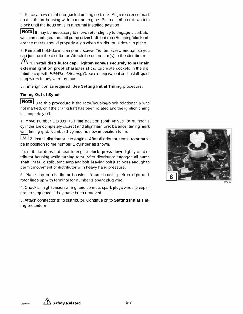
5-7Elect/eng
2. Place a new distributor gasket on engine block. Align reference markon distributor housing with mark on engine. Push distributor down intoblock until the housing is in a normal installed position.
It may be necessary to move rotor slightly to engage distributorwith camshaft gear and oil pump driveshaft, but rotor/housing/block ref-erence marks should properly align when distributor is down in place.
3. Reinstall hold-down clamp and screw. Tighten screw enough so youcan just turn the distributor. Attach the connector(s) to the distributor.
4. Install distributor cap. Tighten screws securely to maintainexternal ignition proof characteristics. Lubricate sockets in the dis-tributor cap with EP/Wheel Bearing Grease or equivalent and install sparkplug wires if they were removed.
5. Time ignition as required. See Setting Initial Timing procedure.
Timing Out of Synch
Use this procedure if the rotor/housing/block relationship wasnot marked, or if the crankshaft has been rotated and the ignition timingis completely off.
1. Move number 1 piston to firing position (both valves for number 1cylinder are completely closed) and align harmonic balancer timing markwith timing grid. Number 1 cylinder is now in position to fire.
6 2. Install distributor into engine. After distributor seats, rotor mustbe in position to fire number 1 cylinder as shown.
If distributor does not seat in engine block, press down lightly on dis-tributor housing while turning rotor. After distributor engages oil pumpshaft, install distributor clamp and bolt, leaving bolt just loose enough topermit movement of distributor with heavy hand pressure.
3. Place cap on distributor housing. Rotate housing left or right untilrotor lines up with terminal for number 1 spark plug wire.
4. Check all high tension wiring, and connect spark plugs wires to cap inproper sequence if they have been removed.
5. Attach connector(s) to distributor. Continue on to Setting Initial Tim-ing procedure.
Safety Related
34928
6

5-8 Elect/eng
To prevent a possible explosion, operate the blower as rec-ommended by the boat manufacturer before starting engine. Ifthe boat is not equipped with bilge blower, open engine cover orhatch prior to starting and leave open until after engine is run-ning.
Setting Initial Timing1 The timing mark is stamped on the rim of the harmonic balancer.
The timing grid is a scale attached to the timing chain cover. It showsTop Dead Center (marked “0”) and degrees of advance (before) orretard (after). Each division on the scale represents 2 degrees.
Preparation
1. Connect a 12-volt timing light to number 1 spark plug lead, and usethe timing light following the manufacturer’s instructions.
Be careful not to puncture the wire or boot as this would cause ahigh voltage leak. Make sure that spark plug wires are pushed all theway down into the distributor cap terminals and onto the spark plugs.Nipples must be firmly pushed over the terminals, and boots over thespark plugs. Failure to do so can result in ignition of fuel vapors inengine compartment or bilge, and may result in fire or explosion.
2. Start engine and leave running until thoroughly warmed up.
Have someone at controls. Keep hands, hair and clothingaway from rotating parts while making adjustments when engineis running.
3. Adjust idle speed to specified in-gear RPM, then shift into NEU-TRAL. Shut off engine.
Setting Timing
The timing procedure for Delco EST system requires shunting (shut-ting off) the electronic spark advance. Follow the steps that apply toyour specific model.
2 1. Install Timing Test Lead, Volvo Penta P/N 885163-6 A , intodistributor and connect bare lead to a 12-volt engine B+ source. Startengine.
Safety Related
5159
34929
1
2

5-9Elect/eng
2. Direct beam of timing light onto timing grid. Loosen distributor clamp,then turn distributor slowly by hand until timing mark is set at the appro-priate timing figure. See Tune-up Specifications in the General Infor-mation section of the Engine Service Manual .
3. Recheck timing mark; reset if necessary. Tighten clamp bolt.
4. Stop engine. Remove adaptor plug.
Ignition Coil Replacement5 1. Remove ignition coil to distributor cap high tension lead E , two
pin connector (purple and gray wires) F , and two pin connector (pinkand brown wires) G from the ignition coil.
6 2. Remove two screws H securing coil to engine block and re-move ignition coil.
7 3. Place coil in a vise. Wear eye protection . Remove tworivet heads I . Drive the rivets out of the coil. Save the bracket piecesJ .
8 4. Assemble the two bracket pieces J and the coil using two screwsand nuts K provided in the replacement ignition coil kit. Tighten screwssecurely.
9 5. Mount the coil assembly to the engine block. Secure with twobolts H . Tighten to 20-25 ft. lbs. (27-34 N•m).
10 6. Attach two pin connector (pink and brown wires) G to the coil asshown. Attach two pin connector (purple and gray wires) F to the coilas shown.
11 7. Apply marine EP/wheel bearing grease or equivalent to the hightension lead terminal E and attach it to the ignition coil.
Safety Related
34930 34931 25545
25551
34942
34943
34944
8
5 6 7
9
10
11

5-10 Elect/eng
Ignition System Problems
Engine runs sluggish, overheats. Check:
• timing• for proper fuel• compression and for carbon buildup
Engine pings. Check:
• timing• for proper fuel• compression and for carbon buildup• spark plugs for proper heat range
Engine starts hard. Check:
• for spark• spark plugs• compression• battery• distributor cap
Engine misfires. Check:
• spark plugs and leads• rotor and distributor cap• coil • engine firing order and plug wire routing• engine timing• engine operating in S.L.O.W.
Engine cranks but doesn’t start. Check:
• for spark• coil primary and secondary circuit wiring• tachometer and wiring• primary circuit wiring to ignition coil• primary circuit wiring to distributor• ignition pickup coil• ignition module

5-11Elect/eng
Specifications
Total Spark Advance
3.0 GS Models
600 RPM .......................................................................... 8°1000 RPM ........................................................................ 13°1500 RPM ........................................................................ 15°2000 RPM ........................................................................ 17°2500 RPM ........................................................................ 18°3000 RPM ........................................................................ 19°3500 RPM ........................................................................ 20°4000 RPM ........................................................................ 20°4600 RPM ........................................................................ 21°
4.3 GL Models
86 AKI Fuel Engine RPM 89 AKI Fuel
18° 600 23°21° 1000 26°23° 1500 28°24° 2000 29°25° 2500 30°25° 3000 30°25° 3500 30°25° 4000 30°25° 4600 30°
Ignition and Pickup Coils
Ignition Coil
Primary Resistance, in Ohms @ 75° F ..........0.35-0.45Secondary Resistance, in Ohms @ 75° F 7500 - 9000
Pickup Coil
Resistance, in Ohms @ 75° F .......................... 700-900

5-12 Elect/eng
Ignition Circuit3.0 GS Models4.3 GL Models
1 Black2 Red3 40 Amp Fuse4 Red/Purple5 20 Amp Fuse6 Purple7 Gray8 High Tension Lead9 Spark Plug Lead10 Spark Plug11 Tachometer12 Pink13 Brown14 Inductor
DRC7516
109
6
7A
B
AB8
13
BA
CD
BA
12
14
1
1
2
3
51
6
44
6
7
AC
S MMA
B
PUL
11
G
+12V
+-
R40
6
42

6-1Elect/eng
Section 6Ignition System
Prestolite Integral BID
5.0 GL Models 5.7 GS Models
Table of Contents
DistributorInitial Timing .................................................................................... 6-9Installation ....................................................................................... 6-7Removal ........................................................................................... 6-5Service ............................................................................................. 6-6
Ignition Coil ......................................................................................... 6-5Ignition System
Operation ......................................................................................... 6-2Problems ........................................................................................ 6-13Troubleshooting ............................................................................ 6-10
Specifications ................................................................................... 6-15Wiring Diagram ................................................................................. 6-14
Safety Warnings
Before working on any part of the electrical system, read the Safetysection at the end of this manual.
The original mounting, support and routing of electrical system partsconform with U.S. Coast Guard requirements. It is important to main-tain the original mounting, support and routing after servicing theelectrical system to prevent possible fire and explosion in boat’sengine compartment.
Do not substitute automotive parts. Volvo Penta marine componentsmeet U.S. Coast Guard regulations for external ignition proof opera-tion and marine use. Volvo Penta marine components are speciallydesigned not to cause ignition of fuel vapors in the bilge or enginecompartment. The use of automotive parts can result in fire and ex-plosion.
Sealants, Lubricants and Adhesives
Black neoprene dipMarine EP/wheel bearing grease
Silicone grease
6

6-2 Elect/eng
Ignition System Operation
To clarify operatingprinciples as well as to simplify the process of trac-ing troubles, it should be understood that the ignition system containstwo separate circuits.
1 The primary circuit carries the low voltage current supplied by thebattery or alternator. In addition to these sources of electrical energy,the primary circuit contains the ignition switch A , primary winding B
of the ignition coil, electronic control module and sensor C located inthe distributor, and all low tension wiring.
2 The secondary circuit carries the high voltage surges producedby the ignition coil which results in high voltage spark between theelectrodes of the spark plug in the engine cylinders. This circuit con-tains the secondary winding D of the coil, coil to distributor high ten-sion lead, distributor rotor and cap E , high tension ignition leads andspark plugs.
1 The electronic ignition system is “integrated”, in that the electron-ics are housed inside the distributor. Only two connections are madeto the ignition coil. The electronic control module contained in the dis-tributor is connected to the battery via the ignition coil positive termi-nal, and grounded through the distributor base.
3 A sensor F and trigger wheel G replace the points and con-denser in the distributor, and control the precise timing needed to firethe spark plugs. The electronic module H controls timing and ignitioncoil saturation by accurately making and breaking the ignition coil pri-mary circuit.
4 This ignition system is known as a “tuned” system. It uses anoscillator as its sensor. Acting as a “metal detector”, it senses the trig-ger wheel teeth turning with the distributor shaft. The presence of metal(each tooth) causes a change to occur in the oscillator which in turncommands the control unit transistor switch to turn off.
5 This “off” condition causes the primary current to stop flowing.The magnetic field, which built up during the “on” time, will collapseacross the secondary coil winding causing a high voltage to fire thespark plug.
DR4017
DR4016
25200
DR3563
DR3564
1
2
3
4
5

6-3Elect/eng
6 The sensor F is a coil of very fine wire molded into a plastic hous-ing. This plastic housing is mounted on the base plate and connecteddirectly to the circuit board. The sensor is serviced as an assembly withthe electronic control module.
7 The electronic control module is a completely self-contained solidstate device which is encapsulated with potting compound to provide avibration and moisture proof barrier. It is not repairable and, if neces-sary, must be replaced as a complete assembly.
8 The distributor is of a conventional design using a centrifugal ad-vance mechanism to control timing.
9 The ignition coil used with this system has a low resistance primarywinding. A low resistance primary winding achieves high output for start-ing. A resistor wire is not used as primary current is regulated in theelectronics.
10 As mentioned before, this system operates as a metal detectingsystem. The detected metal is each tooth of the trigger wheel when it isin close proximity to the sensor coil. The system is not speed sensitive,that is, it is not necessary to “generate” an electric current by turning thedistributor shaft, and will operate at any speed above zero RPM.
11 When a tooth of the trigger wheel is near the sensor, metal is de-tected I , the oscillator is at a low level J , the transistor is off K , and noprimary current flows. This condition can be compared to “points open”L .
12 When the trigger wheel is away from the sensor, metal is not de-tected M , the oscillator is at a high level N , the transistor is on O , andcurrent flows in the primary winding. This condition can be compared to“points closed” P .
25630 25629 25192
25628
DR3565
DR3566
DR3567
6 7 8
9
10
11
12

6-4 Elect/eng
The high voltage surge produced in the secondary winding of the igni-tion coil travels through the cable to the center of the distributor cap,through the rotor to the adjacent distributor cap segment from which itis conducted to the proper spark plug by the high tension ignition wires.The high voltage surge jumps the gap between the insulated centerelectrode and the grounded side electrode of the spark plug, produc-ing the spark required to ignite the fuel-air charge in the selected com-bustion chamber of the engine.
The sequence of action described above is repeated as each tooth ofthe trigger wheel moves past the sensor coil, and causes the transistorto be turned on and off.
The timing of the spark with respect to the piston position in the cylin-der must vary in accordance with operating conditions if best engineperformance is to be obtained. The spark advance for obtaining satis-factory idling should be as low as possible. At high speed, the sparkmust occur earlier in the compression stroke in order to give the fuel-air mixture ample time to ignite, burn and deliver its power to the pistonas it starts down on the power stroke.
Control of spark timing to satisfy these constantly changing operatingrequirements is obtained in two ways, as follows:
Initial manual setting of distributor is made so that a tooth of the triggerwheel passes the sensor coil at a specified position of the piston, asindicated by the timing mark on the crankshaft pulley.
1 Centrifugal advance is governed by engine speed. The centrifu-gal advance mechanism consists of an advance cam, a pair of ad-vance weights A , two springs B and a weight base plate.
At idle speeds the springs hold the advance weights so that there is nospark advance, and the spark occurs in accordance with the initialmanual setting of the distributor.
As speed increases, centrifugal force causes the advance weights tothrow outward and push against the advance cam. This rotates theweight plate causing the teeth of the trigger wheel to pass by the sen-sor coil earlier in the compression stroke, so that the timing is advanced.
25192
1

6-5Elect/eng
Ignition Coil
2 Special Tools Required: Ignition Tester
Most ignition coils that are replaced are classified as weak. Many coilsrejected as weak actually test up to specifications and give normal per-formance.
A coil that actually is weak will first affect engine performance when theignition reserve is at a minimum. This may be in starting, low speedacceleration or top speed. Eventually, the engine will fail to start.
High resistance connections in either the primary or secondary circuitwiring will react the same as a weak coil. Wide spark plug gaps, whichrequire higher voltage than the coil can produce, will put the coil undersuspicion. High compression and lean carburetion increase the voltagerequirements, and lead to many needless coil changes. Leakage of hightension current through moisture on an unprotected coil terminal mayproduce carbon tracks which weaken the coil output voltage. For thisreason, the nipple on the coil high tension terminal must be properlyinstalled and in good condition.
When an ignition coil is suspected of being defective it should be testedon a reliable coil tester according to instructions supplied with the instru-ment, before being replaced.
Distributor Removal
1. Disconnect the distributor primary wires at the ignition coil. Discon-nect high tension leads from distributor cap. Remove distributor cap.
2. Crank engine so number 1 cylinder is in firing position. Note rotor tipposition, and place a reference mark at this point on distributor housingso rotor/distributor housing can be realigned during installation.
3. Place a mark on the distributor base and engine, so that the distribu-tor can be replaced in its original position during installation.
If engine is cranked while distributor is out, complete ignitiontiming procedure must be followed. See Distributor Installation andInitial Timing procedure.
22310
2

6-6 Elect/eng
4. Remove distributor clamp and lift distributor from engine. Discardgasket.
Distributor Service
Do not substitute automotive parts. Volvo Penta marine com-ponents meet U.S. Coast Guard regulations for external ignitionproof operation and marine use. Volvo Penta marine componentsare specially designed not to cause ignition of fuel vapors in thebilge or engine compartment. The use of automotive parts can re-sult in fire and explosion.
Disassembly and Inspection
Major components can be serviced without removing the dis-tributor from the engine.
1. Remove the cap from the distributor. Some engines may requireseveral high tension leads be removed to allow the cap to be movedout of the way. Mark the leads and terminals they were removed fromso they can be replaced in the correct firing order.
2. Wipe out distributor cap with clean cloth and inspect it for chips,cracks and carbonized paths which would allow high tension leakage.Such defects require replacement of the cap. Clean loose corrosionfrom surfaces of terminal segments inside the cap. Do not use emerycloth or sandpaper. If segments are deeply grooved, cap should bereplaced. Pull cables from terminal sockets and inspect sockets forcorrosion. Clean sockets using a stiff wire brush to loosen corrosion.Lubricate sockets with marine EP/wheel bearing grease before reassem-bly of high tension leads. Check carbon contact for excessive wear.
1 3. Remove the rotor and inspect it. If rotor is cracked or rotor tip isbadly burned, rotor must be replaced.
2 4. Loosen the sensor screw A . Remove two screws and lockwashers B , then lift out the sensor/ignition module assembly. Removethe purple and black wires from the ignition coil if this assembly is to bereplaced.
2 5. Inspect trigger wheel for signs of contact with sensor. Checkdistributor shaft for excessive wear between the shaft and bushings inhousing.
3 6. Inspect for excessive wear between centrifugal weights andadvance cam or pivot pins. Turn advance plate until weights are fullyextended, then release and allow weights to return. Repeat severaltimes. Springs should return weights to stop without sticking, and thereshould be no excess free play.
Safety Related
25140
25200
25192
1
2
3

6-7Elect/eng
7. Distributor housing: Spark suppression screens must betightly in place.
Reassembly
1. Apply silicone grease to the bottom edge of the sensor/ignition mod-ule.
2 2. Install sensor/ignition module assembly into the distributor hous-ing and secure with two screws and lock washers B .
2 3. Rotate the engine until one of the trigger wheel teeth lines upwith the mark on the sensor.
4 4. Adjust the sensor air gap by sliding the sensor in or out until an0.008 in. (0,203 mm) measurement can be taken between the sensorand the trigger wheel tooth. Tighten the sensor mounting screw A se-curely.
1 5. Install the rotor making sure to align the notch in the distributorshaft with the rotor. Push the rotor down until it seats.
6. Attach the purple distributor lead to the positive (+) terminal of theignition coil. Attach the black distributor lead to the negative (-) terminalof the ignition coil. Coat the terminals with black neoprene dip.
7. Reinstall the distributor cap. Tighten screws securely to main-tain external ignition proof characteristics. Replace any high tensionleads that were removed. Pay close attention to high tension lead routingand firing order.
8. Check ignition timing as required. See Finish Timing procedure.
Distributor Installation
If the distributor has not been removed and the engine will run, continueon to the Initial Timing procedure.
Engine Not Disturbed
Use this procedure if the rotor/housing/block relationship wasmarked, and the crankshaft has not been rotated. If ignition/valve timingrelationship has been disrupted or engine has been cranked with dis-tributor out, install distributor following Timing Out of Synch procedure.
Safety Related
25146
4

6-8 Elect/eng
1. Position rotor about one-eighth turn clockwise from the rotor refer-ence mark previously placed on the distributor housing.
2. Place a new distributor gasket on engine block. Align reference markon distributor housing with mark on engine. Push distributor down intoblock until the housing is in a normal installed position.
It may be necessary to move rotor slightly to mesh distributorgear with camshaft gear, but rotor/housing/block reference marks shouldproperly align when distributor is down in place.
3. Reinstall hold-down clamp and screw. Tighten screw enough so youcan just turn the distributor. Connect purple primary wire to coil posi-tive terminal and black primary wire to coil negative terminal. Coat ter-minals with black neoprene dip.
4. Install distributor cap. Tighten screws securely to maintainexternal ignition proof characteristics. Lubricate sockets in the dis-tributor cap with marine EP/wheel bearing grease and install spark plugwires if they were removed.
5. Time ignition as required. See Initial Timing procedure.
Timing Out of Synch
Use this procedure if the rotor/housing/block relationship wasnot marked, or if the crankshaft has been rotated and the ignition tim-ing is completely off.
1. Move number 1 piston to firing position (both valves for number 1cylinder are completely closed) and align harmonic balancer timingmark with timing grid. Number 1 cylinder is now in position to fire.
2. Install distributor in engine. After distributor seats, rotor must be inposition to fire number 1 cylinder.
If distributor does not seat in engine block, press down lightly on dis-tributor housing while turning rotor. After distributor engages oil pumpshaft, install distributor clamp and bolt, leaving bolt just loose enoughto permit movement of distributor with heavy hand pressure.
3. Place cap on distributor housing. Rotate housing left or right untilrotor lines up with terminal for number 1 spark plug wire.
4. Check all high tension wiring, and connect spark plugs wires to capin proper sequence if they have been removed.
Safety Related

6-9Elect/eng
5. Connect black primary wire to coil negative (–) terminal. Connect purpleprimary wire to coil positive (+) terminal. Continue on to Initial Timingprocedure.
To prevent a possible explosion, operate the blower as recom-mended by the boat manufacturer before starting engine. If the boatis not equipped with bilge blower, open engine cover or hatch priorto starting and leave open until after engine is running.
Initial Timing
1 The timing grid is stamped on the rim of the harmonic balancer. Thetiming mark is cast into the timing chain cover. It shows Top Dead Center(marked “O”) and degrees of advance (before) or retard (after). Eachdivision on the scale represents 2 degrees.
1. Connect a 12-volt timing light to number 1 spark plug lead, and usethe timing light following the manufacturer’s instructions.
Be careful not to puncture the wire or boot as this would cause ahigh voltage leak. Make sure that spark plug wires are pushed all theway down into the distributor cap terminals and onto the spark plugs.Nipples must be firmly pushed over the terminals, and boots over thespark plugs. Failure to do so can result in ignition of fuel vapors inengine compartment or bilge, and may result in fire or explosion.
2. Start engine and leave running until thoroughly warmed up and chokevalve is wide open.
Have someone at controls. Keep hands, hair and clothing awayfrom rotating parts while making adjustments when engine is run-ning.
3. Adjust idle speed to specified in-gear RPM, then shift into NEUTRAL.
4. Direct beam of timing light onto timing grid. Loosen distributor clamp,then turn distributor slowly by hand until timing mark is aligned with thecorrect degree on the timing grid. See Tune-up Specifications in theGeneral Information section of the Engine Service Manual .
Safety Related
494781

6-10 Elect/eng
5. Recheck timing mark; reset if necessary. Tighten clamp bolt. Re-check idle speed and mixture adjustments.
Ignition System Troubleshooting
Due to design and operating characteristics of this ignition sys-tem, a high voltage discharge in the coil secondary circuit may occurwhen the ignition switch is turned “ON” and “OFF”. The engine doesnot need to be cranked for this to occur. Always ground the coil hightension lead any time it is disconnected from the distributor. Failure todo so may result in fire and explosion if gas vapors are present.
Ignition systems sometimes develop more than one problem.Be sure to complete the entire troubleshooting procedure before re-turning the boat to service.
1. Check simple things first. Inspect the following and correct any prob-lems found before preceding.
• Check the coil tower for carbon tracking. Check pri-mary wires for tight connections and proper polarity.Make sure the tower is clean and dry. Check coil nipplefor proper sealing and insulating qualities. If flash overoccurs here, the engine will not start.
• Check the distributor cap for carbon tracking and dirtinside and outside. Moisture and dirt make a good pathfor flash over. It is very important that the cap be clean.Once a track has started, the cap must be replaced.Check the rotor for the same condition.
• Check all high tension leads for proper resistance;3,000-7,000 ohms per foot of lead length. Also checkfor poor insulation, burning, cracking and deteriorationof the lead, and torn or cracked plug and distributorcap boots.
• Check spark plugs for fouling, proper gap and crackedinsulators. Wipe insulators clean before installing boots.
2. Check for spark from the ignition coil to the distributor, andfrom the distributor to the spark plug using a kilovolt meter. Follow themeter manufacturer’s instructions when performing the tests. Do notallow open sparks to occur. Open sparks can ignite fuel and airvapors that may be present in the bilge area and cause a fire orexplosion .
3. If no spark occurred, remove the distributor cap and rotor, and aligna trigger wheel tooth with the center of the sensor. Check sensor airgap, which should be.008 in (0,203 mm). Note that the sensor will op-erate from a very small gap to a large gap. If the gap is incorrect, resetto .008 in. (0,203 mm) and repeat the spark test. Be sure the distribu-tor shaft turns and is not broken or bent.
Safety Related

6-11Elect/eng
Primary Circuit Voltage Tests
Position the trigger wheel so that the sensor isbetween two teeth. Turn on the key switch. Primary cur-rent should flow.
1 1. Connect a voltmeter across the battery termi-nals A B . The meter should read between 12 and 13volts. Recharge the battery if the voltage is low.
1 2 2. Connect the voltmeter between the nega-tive battery terminal A or engine ground and the coilpositive terminal C . The reading should be within onevolt of the battery voltage in the previous stop. Performa voltage drop test if the voltage is more than one voltlow.
1 2 3. Connect the voltmeter between the nega-tive battery terminal A or engine ground and the coilnegative terminal D . The reading should be between 4and 8 volts.
If voltage is 4 to 8 volts, ground the high tension towerof the coil. Place a screwdriver in front of the sensorface. This will discharge the coil. The voltage should nowread 12 to 13 volts. If not, either the coil or the sensor/circuit board assembly is faulty. Test the coil and replaceif defective. Repeat the screwdriver test. If no spark,replace the sensor/circuit board assembly and reset thesensor air gap.
If voltage is lower than 4 volts, remove the wire from thenegative terminal D of the coil. Reconnect the voltme-ter to the negative terminal.
• 12-13 volts - sensor/circuit board assem-bly is shorted. Replace assembly.
• 0-4 volts - possible open coil primary cir-cuit. Replace coil.
If voltage is higher than 8 volts, check for an open dis-tributor ground circuit or shorted coil primary circuit.
• Distributor ground bad - repair.
• Distributor ground is good - replace sen- sor/circuit board assembly.
• Shorted coil primary circuit - replace coil.
DR5066 DR5067
1 2

6-12 Elect/eng
Voltage Drop Test
Position the trigger wheel so that the sensor isbetween two teeth. Turn on the key switch. Primary cur-rent should flow.
1 2 1. Connect the positive voltmeter lead to thepositive battery post B , and the negative voltmeter leadto the coil positive terminal C . The meter should readless than one volt. Check for poor connections at all at-tachment points. A fluctuation indicates a poor connec-tion and repairs must be made before proceeding. Poorconnections cause heat and get worse, until there is nocurrent flow.
1 2 2. Connect the positive voltmeter Iead to thesensor/circuit board assembly case D , and the nega-tive voltmeter lead to the negative battery post A . Thevoltmeter reading should be less than one volt. If thereading is higher than one volt, tighten the system groundconnections and inspect the battery ground cable. Checkthat the sensor/circuit board assembly mounting screwsare secure. Repeat the test. Replace the battery groundcable if necessary.
3. Check the distributor advance mechanism along withbasic ignition timing. Be sure to operate the engine atthe correct idle speed to be sure of an accurate basictiming adjustment.
DR5066 DR5067
1 2

6-13Elect/eng
Ignition System Problems
Engine runs sluggish, overheats. Check:
• timing and automatic spark advance• for proper fuel• compression and for carbon buildup
Engine pings. Check:
• timing and automatic spark advance• for proper fuel• spark plugs for proper heat range• compression and for carbon buildup
Engine starts hard. Check:
• for spark• spark plugs• compression• bypass circuit• battery• distributor cap
Engine misfires. Check:
• spark plugs and leads• rotor and distributor cap• coil• for loose connections at coil and ignition switch• engine firing order and plug wire routing• engine timing• engine operating in S.L.O.W.
Engine fires when cranked, stops when key is released. Check:
• wiring circuit• ignition switch and connections
Engine cranks but doesn’t start. Check:
• for spark• coil and wiring• bypass to coil positive (+) terminal• engine timing and plug wire routing• tach and wiring

6-14 Elect/eng
Ignition Circuit5.0 GL Models5.7 GS Models
1 Battery 10 Ignition Coil2 Black 11 Distributor3 Red 12 Tachometer4 40 Amp Fuse 13 Gray5 Red/Purple 14 High Tension Lead6 Main Cable Connector 15 Spark Plug Lead7 20 Amp Fuse 16 Spark Plug8 Ignition Switch9 Purple
* Optional Equipment
DRC7515
1
S
C A
M
BM
+_
2
3
10
14 15
16
99
9
9
6
2
2
2
12
SIGNAL+12V
G
4
6
8
A
L
4
5
5
5
7
811
13
13
R40
3

6-15Elect/eng
Specifications
Total Ignition Spark Advance
86 AKI Fuel Engine RPM 89 AKI Fuel
3° 600 8°7° 1200 12°
11° 1600 16°14° 2000 19°18° 2400 23°22° 2800 27°25° 3200 30°26° 3600 31°26° 4000 31°26° 4600 31°
Ignition Coil
Operating Amperage @ 75° F ........................................ 1.0 MaximumPrimary Resistance, in Ohms @ 75° F .............................. 1.26 - 1.54Secondary Resistance, in Ohms @ 75° F ..................... 9400 - 11000
Coil must sustain 25-30 kv for 30 seconds
Distributor
Sensor Air Gap ................................................... 0.008 in. (0,203 mm)


Elect/eng 7-1
Table of Contents
Carburetor Operation .......................................................................... 7-3Carburetor Replacement
3.0 GS Models .................................................................................7-124.3 GL Models .................................................................................7-125.0 GL Models .................................................................................7-125.7 GS Models .................................................................................7-12
Carburetor Service and Adjustments - 2V Models3.0 GS Models ................................................................................. 7-114.3 GL Models ................................................................................. 7-115.0 GL Models ................................................................................. 7-115.7 GS Models ................................................................................. 7-11
Electric Fuel Pump - 4.3 GL, 5.0 GL, and 5.7 GS ModelsFilter Bracket Replacement ........................................................... 7-28Operation ......................................................................................... 7-24Relay Ohmmeter Tests .................................................................... 7-33Replacement ................................................................................... 7-25Specifications ................................................................................. 7-30Troubleshooting .............................................................................. 7-29Wiring Diagram ............................................................................... 7-34
Fuel Filter Replacement ...................................................................... 7-63.0 GS Models ................................................................................... 7-6Canister ............................................................................................. 7-7Carburetor ......................................................................................... 7-7
Mechanical Fuel Pump and Vent Hose3.0 GS Models ...................................................................................7-4
Pressure Testing ...........................................................................7-4Replacement ..................................................................................7-5Specifications ................................................................................7-5Vacuum Testing .............................................................................7-4
Sealants, Lubricants and Adhesives..................................................7-2Specifications, Carburetor ................................................................. 7-37Tanks, Lines, Valves, and Fittings ....................................................... 7-8Tools Required ..................................................................................... 7-2Torque Values - All Models ................................................................ 7-37Troubleshooting
Boat Fuel System .............................................................................7-8Carburetor ....................................................................................... 7-22Engine Fuel System ....................................................................... 7-35
Section 7 Fuel Systems – Carbureted Models
7

7-2 Elect/eng
Tools Required
Vacuum GaugeFuel Pressure Gauge
#2 Clutch Type Screwdriver
Sealants, Lubricants and Adhesives
Volvo Penta gasket sealing compound
Black neoprene dip
Pipe sealant with Teflon
Safety Warnings
Before working on any part of the fuel system, read the Safetysection at the end of this manual.
The original mounting, support, and routing of the fuel systemparts conform with U. S. Coast Guard requirements. It is impor-tant to maintain the original mounting, support, and routingafter servicing the fuel system.
Do not substitute automotive parts. Volvo Penta marinecomponents meet U.S. Coast Guard regulations for externalignition proof operation and marine use. Volvo Penta marinecomponents are specially designed not to cause ignition offuel vapors in the bilge or engine compartment. The use ofautomotive parts can result in fire and explosion.
Gasoline is extremely flammable and highly explosive undercertain conditions. Ensure good ventilation. Do not smoke orallow open flames or sparks near fuel system or in enginecompartment while servicing.
When adjusting a carburetor while the engine is running orbeing cranked, use extreme care to avoid getting hands,fingers, or clothing caught in the alternator and water pumpbelts, pulleys, and other moving parts.

Elect/eng 7-3
Carburetor Operation
The carburetor is a metering device for mixing fuel and air. At idle speed,an engine requires a mixture of about 8 parts air to 1 part fuel. Highspeed mixture is about 12:1.
A small chamber (fuel bowl) holds the fuel. A float valve admits fuel fromthe fuel tank to replace fuel as it is consumed by the engine. Meteringjets in the carburetor fuel chamber control the volume of fuel enteringthe carburetor fuel passages.
1 The intake stroke of the pistons in the engine cylinders creates asuction that draws air through the carburetor throat. A restriction in thecarburetor throat, called a venturi A , has the effect of reducing air pres-sure B at this point by increasing air velocity.
1 The differential in throat and chamber air pressures C causes thefuel to be pushed out of the metering jets through fuel passages and intothe air stream. Here it mixes with the air to form a combustible mixturefor burning in the engine cylinders.
In order to mix air and fuel in the right proportions for all engine speeds,the carburetor design includes idle, off-idle, accelerator, main, power,choke, and where applicable, secondary fuel systems.
To regulate engine speeds, a throttle valve controls the volume of air/fuel mixture drawn into the engine. To compensate for the extra amountof fuel required to start a cold engine, a choke valve is placed above themain venturi on top of the air horn.
When the choke valve is closed, a very rich fuel mixture is drawn into theengine. As the engine starts and warms up, the choke is opened to re-store the normal air/fuel ratio required.
The carburetor throat is frequently called the “barrel”. Carburetors withfour barrels (BBL.) have individual metering jets, throttle and choke platesfor each barrel. For more specific information about carburetor opera-tion, refer to literature available from the carburetor manufacturer.
DR3001
1

7-4 Elect/eng
Mechanical Fuel Pump and Vent Hose
3.0 GS Models
Special tools required: Vacuum and fuel pressure gauge such as Snap-on® Tools MT31IJB or equivalent.
Under normal operation, the transparent vent hose should notcontain fuel or oil. Any evidence of fuel in this hose is an indication ofa ruptured fuel pump diaphragm. Oil in the line indicates a seal failurein the pump allowing crankcase oil to leak into the pump. If fuel or oil isvisible, replace the fuel pump immediately.
If fuel pump is suspected of not delivering proper amount of fuel to thecarburetor, it should be inspected and tested as follows:
When performing procedure below, be careful of gasolinevapor build-up in engine compartment. Gasoline is very explo-sive. Before starting engine, always make sure compartment isfree of fuel vapors to prevent possible fire and explosion.
Pressure Testing
1. Make certain that there is gasoline in fuel tank.
2. Make sure fuel filter cartridge and carburetor fuel filter are new andfree from obstructions.
3. Install pressure gauge to outlet side of pump. Use vacuum gaugeaccording to instructions of the gauge manufacturer. Be sure to followall notes and safety warnings.
4. Start engine and let it run at idle speed. If pressure gauge readingsare as specified, see Boat Fuel System Troubleshooting for addi-tional problem areas. If pressure is too low or too high, replace fuelpump.
A boat fuel system that is restricted, or has an air leak on suc-tion side of fuel pump, can cause an erroneous fuel pump diagnosis.
Vacuum Testing
1. Disconnect boat fuel line at inlet side of fuel filter canister. Capend of line to prevent fuel leakage.
2. Disable ignition system to prevent engine starting whenit’s cranked. Remove all wires from positive (+) terminal of ignitioncoil, and tape them to prevent accidental grounding.
Safety Related

Elect/eng 7-5
3. Install and use vacuum/pressure gauge according to instructions ofthe gauge manufacturer. Be sure to follow all notes and safety warnings.
4. Crank engine and read gauge. Replace fuel pump if gauge does notregister specified amount of vacuum.
Fuel Pump SpecificationsAll Mechanical Fuel Pump Models
Removal
To prevent fire and explosion, disconnect the battery beforeperforming the following replacement procedures.
1 1. Place a container under the fuel pump to catch fuel thatmay drain from pump and lines when lines are removed. Unscrewfuel filter line A at fuel pump, and remove line from elbow. Be sure fuelshutoff is closed or fuel system is plugged to prevent leakage offuel. Be careful not to spill fuel.
1 2. Disconnect carburetor fuel line at fuel pump.
1 3. Cut tie strap and pull vent hose off pump.
4. Support the front of the engine with a sutable engine hoist capable ofsupporting 500 lb (226 kg).
5. Remove starboard engine mounting bolts, and the upper flex mountnut.
6. Remove the engine mount. Do not change the position of the middleflex mount nut.
If the middle flex mount nut is moved, the engine alignmentmust be checked and reset if necessary. See ENGINE INSTALLA-TION found elsewhere in this manual.
7. Remove two fuel pump retaining screws and lock washers. Removefuel pump and gasket from engine; discard gasket. Note orientation ofpump elbows, then unscrew and save for use on new pump.
8. Thoroughly clean fuel pump mounting surface on cylinder block.
Safety Related
37919
* At pump outlet, at idle speed
Fuel Pump Replacement3.0 GS Models
Pressure ................................................ ………………………………………… 5 3/4 to 7 PSI (39,6 to 48,3 kPa)*Vacuum at Cranking Speed ............................. ……………………..……… 9 to 10 in. of Mercury (30 to 34 kPa)
1

7-6 Elect/eng
Installation
1 1. Apply pipe sealant with Teflon or equivalent to old pump elbows.Install elbows, tighten to 48-60 in. lb. (5.4-6.7 N•m), then tighten to origi-nal position. NOTE: Elbows may be angled or different sizes; make sureelbows are installed in correct holes.
DO NOT use Teflon tape on elbow threads. Pieces can breakloose and clog fuel system components.
2. Apply Volvo Penta gasket sealing compound or equivalent to bothsides of a new fuel pump gasket. Place gasket on block and installpump. Install mounting screws and lock washers, and tighten screws to20-25 ft. lb. (27-34 N•m).
2 3. Connect vent hose A to fuel pump. Secure with a new tiestrap.
2 4. Connect carburetor fuel line B to fuel pump. Tighten linenut to 15-18 ft. lb. (20-24 N •m).
2 5. Connect fuel filter line C to fuel pump. Tighten line nut to15-18 ft. lb. (20-24 N•m).
6. Install the starboard engine mount to its orginal position. Use VolvoPenta thread locking compound P/N 1161053 on the mounting boltsand tighten to 35-40 ft. lb. (47-54 N•m).
7. Install the upper flex mount nut to 100-120 ft. lb. (135-165 N•m).
After completing replacement procedures, make sure enginecompartment is free of fuel vapors, then start engine and checkentire fuel system for leaks.
Fuel Filter Replacement
To prevent fire and explosion, disconnect the battery beforeperforming the following replacement procedures. After com-pleting replacement procedures, make sure engine compartmentis free of fuel vapors, then start engine and check entire fuel sys-tem for possible leaks.
3.0 GS Models
Removal
3 Place a shop cloth around the filter canister to catchany fuel. Loosen the yoke screw D and move the yoke to the side farenough to allow removal of the filter canister E and element F . Re-move and discard the element and gasket G .
Installation
3 1. Install a new gasket G inside the bottom of the pumphousing H . Center the spring I inside of the filter canister E . Placethe filter element F on top of the spring. Slide the canister and filterinto place on the pump and secure with yoke J . Tighten the yokescrew D securely.
Safety Related
32016
37919
DR5552
1
2
3

Elect/eng 7-7
2. After completing replacement procedures, make sure engine com-partment is free of fuel vapors, then start engine and check entire fuelsystem for leaks.
Filter Canister
4 1. Unscrew (turn counterclockwise) fuel filter K to remove and dis-card. Check to make sure the original gasket is not stuck on the filterhousing. If so, remove and discard the gasket.
5 2. Lubricate new fuel filter gasket L with clean oil.
3. Install new fuel filter onto fuel filter bracket. Tighten approximatelyone-half turn after gasket makes contact with bracket.
4. Start engine and check for leakage.
Carburetor Fuel Filter
Some models do not have replaceable fuel filters. Instead, theinlet nut contains a screen that should be cleaned periodically.
1. Disconnect the fuel line at the carburetor.
6 2. Remove fuel inlet nut M and gasket N . Take out filter elementgasket O , filter element P , and spring Q (if so equipped).
7 3. Clean inlet filter screen R (non-replaceable) or replace filter el-ement.
4. To reassemble, install spring, new filter element and gasket, andfilter nut and gasket. Tighten inlet nut securely.
5. Connect fuel line and tighten to 11-13 ft. lb. (14.9-17.6 N •m).Start engine and check for leaks.
Safety Related
31931
COB5375
DR2931
DR1504
4
5
6
7

7-8 Elect/eng
Tanks, Lines, Valves, and Fittings
Check for water and dirt in system. Examine complete fuel sys-tem for leaks and loose connections. Check operation of all fuelshutoff valves. Make sure fuel lines are securely fastened to craft toeliminate possible damage from vibration. Check for leaks in tankpickup assembly or a plugged pickup screen.
If fuel system appears to block proper flow of fuel, disconnect lines atdifferent points and blow compressed air through suspect sections.
Do not blow air through sections connected to these compo-nents - fuel pump, carburetor, tank. Check tank for open air vent andclean sediment screen.
Replace all connections which leak and cannot be tightened.
Boat Fuel System Troubleshooting
Fuel systems must be checked for restrictions as part of normal trouble-shooting procedure.
Fuel systems can use anti-siphon valves, elbows, lines, filters, etc.,that may present restrictions greater than can be tolerated by the en-gine fuel pump. Too great a restriction could reduce fuel flow to theengine resulting in poor performance and stopping at higher speed. Anair leak on the suction side of the fuel pump can also cause erraticoperation.
1. Disconnect fuel supply line from tank and fuel filter inlet. Blow airthrough it to make sure it’s clear.
2. Check fuel anti-siphon valve.
The marine industry recommends permanently installed fuel systemsmeet safety standards A.B.Y.C. H-24 and I.C.O.M.I.A. No. 17. Theserequire such systems to have some form of anti-siphon protection. Ananti-siphon valve prevents fuel spillage in case of a break or leak in thedistribution system below the level of fuel in the tank.
Anti-siphon protection may also be afforded by keeping all parts of fueldistribution system above level of tank top when boat is in its normal,unloaded, static floating position. If it’s not possible to keep all linesabove tank, then an anti-siphon valve is required and each tank pickuptube must be so equipped.
Safety Related

Elect/eng 7-9
Anti-siphon valves must have a flow restriction pressure drop of no morethan 35 in. (88.9 cm) of water at a fuel flow rate of 20 gallons (80 litres)per hour.
All models covered in this manual must use a valve designed foruse with 3/8 in. hose. Do not use a smaller valve.
1 If there is any question that an anti-siphon valve is suitable, thenthe following test should be made using a transparent hose:
• Remove anti-siphon valve A from tank and install testfittings and test hose.
• Fill test hose B with water to a vertical height of 20 in.(50.8 cm) C . Water must not run from valve. An occa-sional drop is acceptable. A continuous drip is not ac-ceptable.
• Add more water. Water must run from valve before waterheight is 25 in. (63.5 cm).
An anti-siphon valve passing this test will provide anti-siphon protectionfor a maximum of 28-1/2 in. (72.4 cm) fuel head and also open fully withpump suction. An anti-siphon valve that does not meet these require-ments must be replaced with one which does. This test does not checkability of anti-siphon valve to meet flow requirements.
2 3. Check fuel tank pickup filter screen D :
Recommendations: Use stainless steel, No. 304 wire cloth, 30 mesh,with wire size 0.010-0.012 in. (0.254-0.304 mm) diameter. A cylindricalscreen E equal to pickup tube outside diameter and 1 in. (25.4 mm) longwill provide a screen with required flow area. The screen should be hori-zontal and set slightly above bottom so that maximum amount of fuel canbe used. Make sure screen is not partially restricted by solder and is notbent or kinked.
2 4. Check fuel tank pickup tube F :
Pickup tube must have an I.D. measuring 3/8 in. (9.5 mm) for all models .
Dual engines require two separate pickup tubes, one for each engine.
DR3003
DR3004
1
2

7-10 Elect/eng

Elect/eng 7-11
3.0 GS Models4.3 GL Models 5.0 GL Models 5.7 GS Models
Table of Contents
AdjustmentsAccelerator Pump Clearance ....................................................... 7-20Accelerator Pump Stroke ............................................................ 7-19Choke Unloader ............................................................................ 7-21Choke Vacuum Qualification ....................................................... 7-20Electric Choke .............................................................................. 7-21Float Level - 3.0 GS Models ......................................................... 7-19Float Level - 4.3 GL, 5.0 GL, and 5.7 GS Models ........................ 7-19Idle Mixture and Idle Speed ......................................................... 7-21
CarburetorAssembly ...................................................................................... 7-16Disassembly ................................................................................. 7-13Replacement ................................................................................. 7-12
Specifications ................................................................................... 7-37Torque Values ................................................................................... 7-37Troubleshooting ............................................................................... 7-22
Safety Warnings
When replacement parts are required, use genuine Volvo Penta partsor parts with equivalent characteristics including type, strength, andmaterial. Failure to do so may result in product malfunction andpossible injury to the operator and/or passengers.
After any fuel system maintenance or repairs, always check for leaks.
Always ensure backfire flame arrestor fins are undamaged, and ar-restor is in place and secured before starting engine.
When adjusting a carburetor while the engine is running or beingcranked, use extreme care to avoid getting hands, fingers, or cloth-ing caught in the alternator and water pump belts, pulleys, andother moving parts.
Carburetor Service and Adjustments:2V Models

7-12 Elect/eng
Carburetor Replacement
The following carburetor removal and installation proceduresare similar for all models. The illustrations accompanying the text maynot represent the appearance of actual components on a specific en-gine.
All carburetors covered in this manual are designed for ma-rine use. Do not substitute automotive carburetors because theycan emit fuel vapor into engine compartment, and create a fireand explosion hazard .
Removal
1 1. Remove locknut, flame arrestor cover, vent hose brackets A ,and flame arrestor B . Unscrew flame arrestor stud C if carburetor isto be replaced.
2 2. Cut tie strap and remove fuel pump vent hose D , if equipped.
3 3. Remove cotter pin and washer E , then pull throttle cable offcarburetor arm.
4 4. Disconnect purple/white stripe electrical lead F at choke ther-mostat housing.
5 5. Disconnect fuel line G from carburetor taking care notto spill fuel .
6 6. Remove four carburetor mounting nuts and one flat washer.Note which stud flat washer and choke ground wire H were attachedto. Lift carburetor off manifold, and discard mounting gasket. Notethrottle lever bracket I position, then remove it for transferal to newcarburetor.
Safety Related
21965A 21962 21982A
21956A
21963A
21960
47508
1 2 3
4
5
6

Elect/eng 7-13
Installation
Refer to Specifications and check carburetor model number. Ifwrong model carburetor is used, both high and low speed operation areaffected.
1. Attach throttle lever bracket from old carburetor. Be sure it’s in itsoriginal position. Place new base gasket on mounting studs and installcarburetor.
7 2. Attach flat washer and choke ground wire H to original mount-ing stud. Install carburetor mounting nuts and tighten to 10-14 ft. lb. (13-19 N•m).
5 3. Connect fuel line G to carburetor and tighten to 11-13 ft.lb. (14.9-17.6 N •m).
4 4. Connect purple/white stripe lead F to choke housing.
3 5. Attach throttle cable and secure it with a flat washer andcotter pin E . Spread pin ends to prevent disengagement. Readjustthrottle cable preload as required.
6. Attach vent hose to carburetor fitting if equipped, and securewith tie strap .
7. Screw flame arrestor stud into carburetor (if removed), andtighten to 65-80 in. lb. (7.3-9 N .m).
8 8. Install flame arrestor B and vent hose brackets A . Tightenflame arrestor nut to 30-40 in. lb. (3.4-4.5 N •m). Install flame arrestorcover and tighten nut to 30-35 in. lb. (3.4-4 N•m).
9. Run engine. Check for fuel leaks, and take corrective action ifnecessary.
Carburetor Disassembly
Disassembly of Fuel Bowl and Metering Block
Before beginning disassembly, mount carburetor on a holding fixture or aset of 5/16 in. bolts.
Safety Related
21958
34827
7
8

7-14 Elect/eng
1. Remove primary fuel bowl and metering block. Discard gaskets.
1 2. Remove idle adjusting needles and gaskets A . Discard gas-kets.
1 3. Using a jet wrench, remove main jets B . Lift vent baffle C offpegs.
2 4. Unscrew the power valve D and gasket E . Discard the gas-ket.
5. Float Removal.
3 4 3.0 GS Models: First remove the inlet valve assembly. Loosenlock screw F and turn hex nut G counterclockwise. Remove the as-sembly H . Remove two screws I holding float in place. Remove floatand bracket.
5 4.3 GL, 5.0 GL, and 5.7 GS Models: Using needle-nose pliers,remove float retainer E-clip J . Slide float off shaft. Remove springfrom float. Pull baffle K out of fuel bowl. Lift inlet needle out of seat.Unscrew seat and discard gasket underneath.
6. Unscrew fuel inlet nut to service filtering device. Some models willhave a screen inside the inlet nut (non-replaceable), while others willhave a wire mesh or sintered bronze filter. Clean screen type filters(replace if necessary), and discard and replace bronze filter. Replaceinlet nut gasket.
5 6 7. Remove accelerator pump cover L , diaphragm M , andspring. Verify that the inlet check ball N has the necessary freedom ofmovement to allow the accelerator pump to fill properly. With the bowlinverted (check ball seated), the clearance between the ball and itsretainer should be 0.011-0.013 in. (0,279-0,330 mm). Carefully bendthe retainer to set the specified clearance. The accelerator pump in-let check ball is not serviced separately, and should not be re-moved.
8. Use a solvent soaked cloth to remove old gasket material from me-tering block and float bowl.
11606 20517 20612
20515A
11591
20595
1 2 3
4
5
6

Elect/eng 7-15
Disassembly of Main Body
7 1. Invert carburetor and remove throttle body retaining screws andlock washers O . Remove choke vacuum hose P from throttle body fit-ting. Remove throttle body and discard gasket.
8 9 2. Remove retainer Q from lower end of choke rod R . Re-move thermostatic spring housing S , its retainer T , and gasket U .
10 3. Unscrew choke housing and discard vacuum passage gasket.
11 4. Remove accelerator pump discharge nozzle screw V , then liftpump discharge nozzle W and gaskets X out of main body. Invert mainbody and let accelerator pump discharge needle Y fall into your hand.
5. Do not remove choke plate, choke shaft, choke rod, or nylon guideunless one of them needs to be replaced. The choke plate screws arestaked and must be filed flush with choke shaft prior to removal. Thechoke rod must be lifted out of top of main body before nylon guide canbe removed.
21989
21988
21987
21986
22104
7
8
9
10
11

7-16 Elect/eng
Disassembly of Throttle Body
1 1. Remove accelerating pump operating lever A and retainer B .
2 2. Unscrew and remove throttle cable bracket C from throttlearm.
2 3. Note screw hole number D on throttle arm and acceleratorcam E , then unscrew cam.
Cleaning, Inspection, and Repair
1. Clean carburetor in a carburetor cleaning solvent.
DO NOT immerse throttle body assembly, any rubber parts,plastic parts, diaphragms, or pump plungers in carburetor cleaner. Delrincam on throttle lever and Teflon bushings on throttle shaft will not with-stand soaking in carburetor cleaner. Spray with choke cleaner and blowdry.
2. Use a cloth soaked in solvent to remove old gasket material. Blowout all passages in castings with compressed air. DO NOT pass drillsthrough jets or passages.
3. Inspect idle mixture needles for damage.
4. Examine inlet needle and seat for wear. If worn, replace with newinlet needle and seat assembly.
5. Inspect upper and lower surfaces of carburetor castings for dam-age. Make sure sealing beads on castings have not been damaged.
6. Inspect holes in levers for excessive wear or out-of-round condition.If worn, replace levers.
7. Check all throttle levers and valves for binding or other damage.
Always use new gaskets and O-rings whenever a carburetoris disassembled or overhauled. Make sure that all holes in new gas-kets are properly punched and that no foreign material adheres to gas-kets. Be certain that accelerator pump diaphragm is not cut or torn.
Carburetor Assembly
Assembly of Throttle Body
3 1. Attach accelerator pump cam E . Align proper hole F in camwith specified hole D in throttle arm. See Specifications for correctposition. Install screw and tighten it securely.
21999
21998
21997
1
2
3

Elect/eng 7-17
1 2. Attach throttle cable bracket to throttle arm with two screwsand elastic locknuts. The upper screw must engage middle hole G inthrottle arm. Tighten both screws securely.
1 3. Install accelerator pump operating lever A and retainer B .
Assembly of Main Body
4 1. Drop accelerator pump discharge needle H into its well. Posi-tion accelerator pump nozzle I (with nozzles down and slots facing airvent rib) and gaskets J in main body. Install retaining screw K .
5 2. Insert choke rod L in choke housing shaft lever as choke hous-ing is placed into position on main body. Be sure projection on choke rodis placed under fast idle cam M , so that cam will be lifted when chokeplate is closed. Install choke housing lock washers and screws. Usingneedle-nose pliers, install choke rod clip N .
6 3. Place thermostatic housing gasket on choke housing. Installhousing and engage thermostatic spring on choke lever. Install clampand screws. Adjust thermostatic spring housing by aligning index markO on cover with specified mark P on choke housing.
7 4. Invert main body and install throttle body gasket. Install throttlebody to main body and secure with screws and lock washers Q . Installvacuum hose R from throttle plate to choke housing.
Assembly of Fuel Bowl and Metering Block
8 1. Place accelerator pump diaphragm spring S and diaphragm T
in accelerator pump chamber. The diaphragm must be positioned so thatlarge end of lever disc will be against operating lever. Install cover andretaining screws. Move pump lever to compress diaphragm spring. Thiswill make sure diaphragm is not pinched. Tighten screws securely.
21996A
21995
21994
21989
20614
Safety Related
4
5
6
7
8

7-18 Elect/eng
2. Float Installation.
1 2 3 3.0 GS Models: Install float assembly and retain withtwo screws A . Assemble inlet needle as shown. Apply a light assem-bly oil or petroleum jelly to the inlet needle assembly O-ring B . Installassembly into fuel bowl using gasket C , nut D , gasket E , and screwF . For float setting, refer to Adjustments for proper procedure.
4 5 4.3 GL, 5.0 GL, and 5.7 GS Models: Install inlet needleseat G and new gasket. Install inlet needle and pull clip assembly H .Slide baffle plate I onto ridges in fuel bowl. Install spring J on floatand engage needle pull clip while sliding float onto shaft. Be sure floatspring is between ridges on boss on floor of fuel bowl. Install floatretainer K with needle-nose pliers. For float setting, refer to Adjust-ments for proper procedure.
3. Install filtering device. Insert spring and bronze filter (open endwith gasket faces inlet nut), or wire mesh filter, if applicable. Place anew gasket on inlet nut. Install and tighten to specifications to pre-vent fuel leakage.
6 4. Refer to Specifications for correct power valve identificationnumber. The number L (example 6.5) is stamped on a flat on base ofvalve. There are two types of power valves, and each requires a differ-ent gasket. Valves having multiple drilled fuel openings require a gas-ket having three internal projections. Valves with two rectangular fuelopenings require a gasket with no internal projections. Use of the wronggasket will cause a fuel leak around the power valve.
7 5. Install correct power valve and gasket into metering block.Installation of wrong power valve will result in poor performance.
Safety Related
20613 21992A 21993
11719
11721
DR3061
20517A
1 2 3
4
5
6
7

Elect/eng 7-19
8 6. Using a jet wrench, install jets M into metering block. Refer toSpecifications for correct jet number.
8 7. Using new gaskets, install idle mixture needles N . Turn idlemixture needles in until they just touch seat. Back them off the correctnumber of turns for a preliminary idle adjustment. Refer to Specifica-tions for correct idle mixture setting.
8 8. Position metering block gasket on dowels located on back ofmetering block. Push metering block and gasket onto main body. Posi-tion vent baffle O then float bowl gasket on metering block. Make sureaccelerator passage P is not blocked. Place new gaskets on float bowlscrews, then install float bowl on main metering block and retain withscrews.
Carburetor Adjustments
If the carburetor has just been completely rebuilt, adjustmentsshould be performed in the following sequence. This will ensure that aprevious/subsequent adjustment is not affected. If a rebuild has not beendone, perform only the adjustment(s) that will correct the operationalproblem.
Float Level - 3.0 GS Models Only
9 1. Loosen screw Q and invert fuel bowl. Turn nut R to get an initialadjustment. Top of float S should be level.
9 2. Secure float level setting by holding nut R and then tighteninglock screw Q .
Float Level - 4.3 GL, 5.0 GL, and 5.7 GS Models Only
Do not spill fuel. This will create a fire hazard.
10 Drain fuel from carburetor and remove fuel bowl. Remove float baffle.With bowl inverted, carefully bend curved float arm T that contacts inletneedle to set float level (parallel to fuel bowl). Reinstall bowl using newgaskets .
Accelerator Pump Stroke
11 The accelerator pump stroke is controlled by the pump cam posi-tion. The proper amount of fuel is delivered when attachment screw is inspecified hole of both cam U and throttle arm. See Specifications forposition.
Safety Related
22385
20610
11716
11689
47508
8
9
10
11

7-20 Elect/eng
Accelerator Pump Clearance
1 Block throttle plates in the wide open position, and manually de-press accelerator pump arm A . Use a feeler gauge to check for speci-fied clearance between arm and pump lever screw head. Turn adjust-ing nut B IN to increase clearance and OUT to decrease clearance.This adjustment ensures maximum pump output, full primary throttleopening, plus prevents off-idle hesitation and over-extension of theaccelerator pump diaphragm.
After making this adjustment, check accelerator pump opera-tion. The pump should start to move as soon as the throttle shaft moves.This is called “immediate pump pick-up”. Any delay in pump move-ment will result in an off-idle hesitation or lag. If pump fails to moveimmediately, check for bent or worn parts, misadjusted pump clear-ance, or an improperly positioned pump cam.
Choke Vacuum Qualification
1. Remove choke housing cover.
2 2. Push choke piston against the adjustable screw stop C . Usea convenient tool or a paper clip to push with. Exercise care not toscratch the inner piston ball-link seat or the casting bore.
3. With the piston held against the adjustable screw stop, apply lightpressure to the choke housing lever in a closing direction, until all freeplay is removed from the linkage.
2 4. Check the choke opening with the correct drill size. Adjust-ments are made by turning the adjustment screw stop C (inward forless opening, outward for more opening).
Care must be taken not to back out the adjusting screw somuch that the piston will partially pass the screw and then be gougedby inward screw adjustment.
31903
DR2999
1
2

Elect/eng 7-21
Electric Choke
The electric choke has an adjustment to control its opening rate. Byloosening the clamp screws that retain the thermostatic spring housing,the housing can be turned to alter adjustment. Turning housing in a coun-terclockwise direction will richen mixture and make choke stay on longer.Turning spring housing in opposite direction (clockwise) will lean outmixture and make choke come off sooner.
The electric choke cap is grounded with an external ground wire.Make sure all ground components are clean and free of corrosion.
3 1. Set choke so that index mark on choke cover D is alignedrelative to index marks on choke housing E as specified.
2. If a richer or leaner mixture during warmup period is desired, it canbe obtained by rotating thermostat cover one mark at a time. Never setindex mark on cover more than two graduations off specified setting.
Choke Unloader
4 1. Hold throttle valves in a wide open position. Insert correct sizedrill between lower edge F of choke valve and inner wall of air horn.
2. Press finger lightly against choke control lever. A slight drag shouldbe felt as drill is pulled out.
5 3. To adjust, bend tab G on throttle shaft kick-down lever untilcorrect opening has been obtained.
Idle Mixture and Idle Speed
1. Initially set idle mixture by turning idle mixture screws inward untilthey are lightly seated, then turn screws outward the specified turns. Donot turn screws tightly against seats. Both the screw tips and castingseats may be damaged. Replace screws with damaged tips.
2. Final adjustments are made with engine running at operating tem-perature. Refer to Specifications for correct idle RPM.
3. Use a tachometer to make final adjustments. Turn idle mixture screwsinward until engine RPM begins to drop due to lean mixture. Back screwsout evenly and alternately until the best idle RPM is reached. If RPMbegins to drop (due to an overly rich mixture) before reaching the speci-fied RPM, turn screws inward until maximum engine RPM and smooth-ness is achieved.
4. Readjust idle speed as necessary. Always adjust idle speed last.
15313
22386
11714
3
4
5

7-22 Elect/eng
Carburetor Troubleshooting
FLOAT ADJUSTMENT
Determines fuel level in float bowls
High Float Levels
1. Raises fuel level2. Speeds main and secondary system start-up3. Promotes primary and secondary flooding, stalling4. Increases fuel consumption
Low Float Levels
1. Lowers fuel level2. Delays main and secondary system start-up3. Results in primary and secondary flat spots, hesitation4. Can decrease maximum fuel flow capability
ACCELERATOR PUMP STROKE
Cam type and placement determines volume of fuel per stroke
Performance Problems
1. Lean or rich condition2. Hesitation or acceleration lag throughout RPM range3. Damage pump diaphragm
ACCELERATOR PUMP CLEARANCE
Provides full pump output
Performance Problems
1. Prevents overstroking pump2. Prevents off idle hesitation
CHOKE VACUUM QUALIFICATION
Determines amount of choke plate opening that occurs after starting a cold engine
Performance Problems
Plate closes too far (too rich):
1. Engine loads up2. Runs rough, may die3. Increase fuel consumption
Plate opens too far (too lean):
1. Engine runs rough2. Will die quickly3. Hesitation upon acceleration
(continued on next page)

Elect/eng 7-23
Carburetor Troubleshooting (cont.)
CHOKE ADJUSTMENT
Determines how long choke stays on
Performance Problems
Choke too rich:
1. Increase fuel consumption2. Difficult hot start
Choke too lean:
1. Poor cold engine performance2. Difficult cold engine starting
CHOKE UNLOADER
Determine amount of choke plate opening at W.O.T. on a cold engine
Performance Problems
1. Affects cold engine at W.O.T.2. Aids starting flooded engine
IDLE MIXTURE
Determines fuel/air volume exiting idle circuit
Performance Problems
1. Rough or unbalanced idle2. Tendency to die3. May diesel or run-on
IDLE SPEED
Used in conjunction with mixture screws to set idle RPM
Performance Problems
1. Idle RPM too high, may diesel or run-on2. Idle RPM too low, may die
SECONDARY THROTTLE PLATE OPENING
Opens secondary throttle plates to allow secondary idle circuits to function
Performance Problems
1. Open too far - high idle RPM2. Closed too much - hesitation during transition from primary to secondary throttle operation3. Sticking closed - hesitation during transition from primary to secondary throttle operation4. Hole in diaphragm - hesitation during transition from primary to secondary throttle operation

7-24 Elect/eng
Electric Fuel Pump
4.3 GL, 5.0 GL, and 5.7 GS Models
Operation
The electric fuel pump utilizes a 12 volt DC motor that runs continuouslyat 4000 RPM whenever the engine is cranked or running. The electricmotor drives a metal gear pump that uses the fuel as coolant. The pumpsupplies fuel at variable PSI as determined by engine load and fuel con-sumption. Excess fuel circulates within the pump past an internal pres-sure regulator. When the regulator is in operation, fuel stops entering thepump. This design eliminates the need for a return line to the fuel tank.
The pump has excellent dry prime characteristics, and can run withoutfuel for up to 30-40 seconds, although running without fuel is not rec-ommended. The carburetor float chamber will run out of fuel before dam-age could occur. The fuel pump has an in-line Radio Frequency Interfer-ence (R.F.I.) suppressor built into the motor’s plastic connector. A sepa-rate circuit breaker provides circuit overload protection.
When the key switch is turned to the “START” position, voltage is sup-plied to the fuel pump relay from the start (“S”) terminal of the assistsolenoid. The relay is activated and battery voltage is applied to the pumpmotor and then to engine ground.
The alternator supplies voltage to the relay from the “light” terminal afterthe engine starts and the key switch is returned to the “RUN” position.The pump relay also receives voltage direct from the battery via the as-sist solenoid, and this circuit is protected by a 6 amp circuit breaker.
A diode in the orange lead prevents voltage feedback from the alternatorto the assist solenoid. This keeps the starter motor from being energizedafter the engine starts. A diode in the alternator green lead preventsdamage to the alternator during cranking. For specific wiring connec-tions, see the Wiring Diagram at the end of this section.
The fuel pump will not run if the key switch is in the “RUN” posi-tion and the engine is not running.
Do not substitute automotive parts. Volvo Penta marine com-ponents meet U.S. Coast Guard regulations for fuel leakage, exter-nal ignition proof operation, and marine use. Volvo Penta marinecomponents are specially designed not to cause ignition of fuelvapors in the bilge or engine compartment. The use of automotiveparts can result in fire and explosion.
Safety Related

Elect/eng 7-25
Electric Fuel Pump Replacement
This pump has been designed to meet U.S. Coast Guard fuelsystems regulations for marine use. Do not substitute other brandsor models that may be similar in appearance. Use of a substitutepump could result in leakage of fuel or fumes, and cause fire andexplosion.
Removal
1. Disconnect positive and negative cables at the battery.
2. Disconnect boat fuel supply line at fuel filter and plugthreaded hole.
1 3. Remove screw securing fuel pump guard A to bracket. Re-move guard to allow complete access to fuel line and pump.
2 4. Cut cut tie straps holding electrical leads to pump. Pull connec-tor B off pump suppressor.
3 5. Using two wrenches, one holding lower pump fitting and otheron fuel line nut, unscrew carburetor fuel line C at pump and pull lineout of fitting.
4 6. Hold the pump end cap with an open end wrench D , and re-move fitting E .
If pump end cap is not held when removing fitting, end capmay rotate and damage internal O-ring that seals pump againstexternal fuel leakage.
5 7. Remove two filter bracket bolts F . Slide pump out of grommetG in upper bracket after last bolt is removed.
Fuel filter may contain fuel; be careful not to spill it.
Safety Related
49528
49572
49519
49570
30628
2
5
4
3
1

7-26 Elect/eng
6 8. To remove fuel filter and bracket from pump, hold pump end capH with an open end wrench, and unscrew adapter at base of pump.
lf pump end cap is not held when removing adapter, end capmay rotate and damage internal O-ring that seals pump against ex-ternal fuel leakage.
Installation
Electric fuel pumps look similar, but have different fuel flow rates.Do not interchange these assemblies.
7 1. Place a new O-ring I on the filter bracket adaptor and position itagainst hex. Do not nick or cut O-ring on threads.
This O-ring is made of a special fuel resistant material. Substi-tution of parts of unknown quality could result in a fuel leak, andthe possibility of fire and explosion.
8 2. Screw filter bracket assembly into pump. Hold lower pump endcap H with an open end wrench and tighten adaptor to 8-10 ft. lb. (11-14N•m).
If pump and cap is not held when installing adapter, end capmay rotate and damage internal O-ring that seals pump against ex-ternal fuel leakage.
5 3. Slide pump up through grommet G and install two bolts F . Tightenbolts to 20-25 ft. lb. (27-34 N•m).
9 4. Install a new O-ring onto the fitting. Do not nick or cut O-ring onthreads.
This O-ring is made of a special fuel resistant material. Substi-tution of parts of unknown quality could result in a fuel leak, andthe possibility of fire and explosion.
Safety Related
30635
30626
30634
49520
6
8
9
7

Elect/eng 7-27
1 5. Screw fitting A all the way into pump outlet. Hold pumpend cap B with an open end wrench and tighten fitting to 60-84 in. lb.(6.8-9.5 N•m).
2 6. Connect fuel line C to pump fitting. Hold fitting A withan open end wrench. Tighten fuel line securely.
If pump end cap is not held when tightening fitting, end capmay rotate and damage internal O-ring that seals pump againstexternal fuel leakage.
3 7. Align connector tabs and push connector onto pump suppres-sor until it clicks into place.
4 8. If the electrical leads were secured to the pump body, securethem with a tie strap.
5 9. Install pump guard D and secure with screw.
10. Remove plug and reconnect boat fuel line. Tighten securely.Attach positive and negative cables at the battery. Run engine andcheck for fuel leaks.
Safety Related
49571
49519
49522
30641
49528
1
3
4
5
2

7-28 Elect/eng
Filter Bracket Replacement
The electric fuel pump filter has an internal seal around the fuelexit point that prevents leakage and drain back. Do not substitute otherfilters that may be similar in appearance. To replace filter canister, referto Fuel Filter Replacement elsewhere in this section.
1. Remove fuel pump and filter bracket assembly from mounting bracket.
2. Unscrew fuel inlet elbow and save for installation on new bracket.
3. Clamp filter bracket in a vise and unscrew adaptor and pump assem-bly. Discard bracket.
4. Thoroughly clean adaptor threads to remove old sealer, then apply PipeSealant with Teflon or equivalent to the threads.
5. Clamp new bracket in a vise. Screw in adaptor and pump assembly,and tighten to at least 10 ft. lb. (14 N•m). Continue tightening adaptor toachieve proper pump/bracket directional alignment. Do not exceed 32ft. lb. (43 N •m) torque.
6. Thoroughly clean threads of inlet elbow to remove old sealer, then ap-ply pipe sealant with Teflon or equivalent to the threads. Screw in elbowand tighten to at least 12 ft. lb. (16 N•m). Continue tightening elbow toachieve proper directional alignment. Do not exceed 32 ft. lb. (43 N •m)torque.
7. Install fuel pump and filter bracket assembly in mounting bracket.
8. Run engine and check for fuel leaks.
Safety Related

Elect/eng 7-29
Troubleshooting Electric Pump Fuel System
1. Start by verifying the pump is receiving a minimum of 12.0 ± 1 volt.Pull connector off pump suppressor. Disable ignition to prevent enginefrom running, then crank engine and check yellow/red lead with a volt-meter. Shut engine off, then check connector black lead with an ohm-meter for a good ground. If voltage is not as specified, or ground pathis suspect, check:
• relay and bracket• fuse• orange lead diode• green lead diode• alternator output at “Light” terminal (13.9-14.7 volts)• wiring related to all of the above
Ensure all items are functioning correctly before proceeding. As volt-age to the pump drops, so will its output capability.
2. Once it’s been established that the pump is receiving proper voltage,separate the engine fuel system from the boat’s fuel system. Discon-nect the supply line at the pump’s fuel filter, and place a pick-up hosein a vented fuel container. The pick-up hose must have a minimumI.D. of 3/8 in.
Do not connect engine fuel system to any supply system having apressure producing device such as an outboard fuel tank with primerbulb, or another electric fuel pump located elsewhere in the boat or atthe fuel tank. The pump is sensitive to additional fuel pressure,and will add this to its own output. The result will be a continuallyflooding carburetor with the possibility of external fuel leaks, andthe potential for fire and explosion.
3. Run engine to see if problem still exists. If problem has been elimi-nated, source is located somewhere in boat fuel system back to, andincluding, the boat fuel tank. If problem still occurs, it’s located some-where in engine fuel system.
Checking Engine Fuel System
1. The electric fuel pump requires an unrestricted, air tight fuel supply.Unscrew the pump fuel filter and check it for debris. Also check that thefilter seals tightly against its fixture and the center mounting threads.Make sure the filter is the correct one for this application. Checkthreads of filter inlet elbow to ensure a tight seal. If any of these condi-tions are in doubt, correct them before continuing.
2. Remove the carburetor fuel inlet nut and inspect the inlet screen orfilter for debris. Clean or replace this item before continuing.
Safety Related

7-30 Elect/eng
3. Check fuel pump mounting position. Pump must always be lo-cated on engine in original factory position. This position is deter-mined by U.S. Coast Guard regulations and must be complied with.Never relocate pump to transom, stringer, fuel tank, or any point otherthan its original location on the engine.
Pressure Testing Fuel System
Pump performance can be verified by checking pump PSI at spe-cific engine RPM. This test must be performed with engine underload; either running in gear on water, or in gear and connected to adynamometer. Use a good quality fuel pressure gauge and connect itinto the fuel line between the fuel pump and the carburetor. Follow thegauge manufacturer’s instructions for installation, and ensure that con-nections are leak free . Refer to the chart below, and run the engine atvarious RPM’s to check pump operating pressure.
Specifications
Pump Performance at a Minimum of 12.0 + 1 Volt
Idle 4.9 - 8.5
1000 4.8 - 8.4
1500 4.7 - 8.3
2000 4.6 - 8.2
2500 4.5 - 8.1
3000 4.4 - 8.0
3500 4.3 - 7.9
4000 4.0 - 7.7
4500 -
4600 3.5 - 7.3
New pumps will generally have lower operating pressures. Asthe pump gears break in, contact improves and pump pressure increasesslightly.
Safety Related
RPM P.S.I.

Elect/eng 7-31
Two other items that would require checking are the screens in eachend of the fuel pump body. This requires removal of the upper elbowand the lower fuel filter adaptor. If screens cannot be sufficiently cleaned,replace the fuel pump. The screens are not serviced separately.
Checking Boat Fuel System
The most common causes of failures in the boat fuel system are due toline restrictions or air entry. Typical restrictions are:
• kinked, bent, or internally swollen fuel lines• fuel lines and/or tank selector valve I.D.’s too small• restricted or wrong anti-siphon valve• cracked or blocked fuel pick-up or screen inside tank• blocked tank vent
Air entry can occur at any point on the suction side of the fuel system.Air in the fuel system is usually indicated by a pump humming or squeal-ing noise.
Pump noise is caused by air being drawn through the fuel pumpgears, but is not always an indicator that something is wrong . Mo-mentary noise has several causes that are not linked to fuel systemfailures:
• pump may squeal for a short time upon start-up as airis expelled
• if ambient temperatures are high, the engine compart-ment will be subjected to hot operating conditions thatmay create vapor in the fuel lines
• a hot engine after shutdown will go into a “hot soak”condition that may produce fuel vapors
• the use of ethanol fuel will also aggravate this conditionas it’s more susceptible to vapor formation
All of these situations are temporary, but may produce vapor that wouldcause pump noise. Pump noise that is continuous, and/or cannot beattributed to any of these conditions, could be an indicator of fuel sys-tem problems.

7-32 Elect/eng
Vacuum Testing Fuel System
This test must be performed with engine under load; either runningin gear on water, or in gear and connected to a dynamometer. Ensurethat all fuel line connections are leak free.
1. Install Vacuum and Fuel Pressure Gauge such as Snap-on® ToolsMT311JB or equivalent, and 8 in. (20,3 cm) of clear, fuel resistant vinylhose into the fuel line at the filter bracket inlet.
2. Start engine and allow it to reach normal operating temperature. Runengine at full throttle for at least 2 minutes; observe vacuum gauge read-ing and check clear hose for air or vapor bubbles. Gauge reading mustnot exceed 4 in. of mercury (Hg) at any time, and there should be nobubbles visible in the clear hose. Compare observations to the following:
Gauge reads 1-4 in. of mercury - air bubbles present
Supply side of fuel system has an air leak. Check points of possible fail-ure as noted under Checking Boat Fuel System . Repair or replace sus-pect part, then make another vacuum test to verify repair.
Gauge reading exceeds 4 in. of mercury
Supply side of fuel system has a restriction. Check points of possiblefailure as noted under Checking Boat Fuel System . Repair or replacesuspect part, then make another vacuum test to verify repair.
Relay Wiring Diode Operation and Failure
Alternator (Green) Lead Diode
This diode prevents current from the assist solenoid/starter relay reach-ing the alternator regulator during engine cranking. This diode can failone of two ways. If the diode becomes shorted (continuity in both direc-tions), the regulator may be damaged and the alternator might not pro-duce the proper amount of current. If the diode becomes open (no conti-nuity in either direction), the fuel pump will not run when the engine isrunning. After a short time, the engine will starve for fuel.
Assist Solenoid/Starter Role (Orange) Lead Diode
This diode prevents current from the alternator “Light” terminal reachingthe assist solenoid/starter relay while the engine is running. This diodecan fail one of two ways. If the diode becomes shorted (continuity in bothdirections), the starter motor will try to engage while the engine is run-ning. If the diode becomes open (no continuity in either direction), thefuel pump will not run when the engine is cranking and may be hard tostart.
Safety Related

Elect/eng 7-33
Relay Ohmmeter Tests
Throughout this section two symbols are used to interpret elec-trical troubleshooting results.
1 This symbol indicates continuity or very low resistance.
2 This symbol indicates no continuity or very high resistance (¥).
To avoid damaging components or troubleshooting equipment,disconnect the battery cables from the battery and remove the relaysbefore proceeding.
1. Use a continuity light or ohmmeter calibrated on appropriate scale totest continuity.
3 2. Connect meter leads to relay terminals 87a and 30.
• The meter must show continuity .4 3. Connect meter leads to relay terminals 87 and 30.
• The meter must show no continuity .5 4. Calibrate an ohmmeter on appropriate scale and connect the
leads to relay terminals 85 and 86.
• The meter must show 70 - 100 ohms.6 5. Connect meter leads to relay terminals 87 and 30. Connect a
12 volt source to relay terminals 85 and 86.
• The meter must show continuity .
7 6. Connect meter leads to relay terminals 87a and 30. Connect a12 volt source to relay terminals 85 and 86.
• The meter must show no continuity .
7. Replace relay if your test results vary.
DR2065 DR2066 DR2149
DR2149A
DR2149B
DR2149C
DR2149D
1 2 3
4
5
6
7

7-34 Elect/eng
Electric Fuel Pump Circuit4.3 GL, 5.0 GL, and 5.7 GS Models
1 Battery 11 6 Amp Circuit Breaker2 Black 12 Remote Control3 Red 13 Yellow/Red4 50 Amp Circuit Breaker 14 Alternator5 Starter Motor 15 Green6 Red/Purple 16 Diode7 Main Cable Connector 17 Orange8 20 Amp Fuse 18 Relay9 Ignition Switch 19 Fuel Pump10 Purple
DRC7521
+ —
CSM M
B
A
85
8786
30
6
EXC
E
B
L2
S
P
85
30
87
86
7.5
40
1
8
9
43
3
6
66
7
63
3
2
2 2
13
11
19 1013
13
15
14
13
12
10
17
16
16
18
18

Elect/eng 7-35
Engine Fuel System Troubleshooting
ENGINE DOES NOT START - IMPROPER STARTING PROCEDURE USED
1. Check fuel level in tank, check fuel tank vent, check fuel in carburetor.2. Check choke for proper operation.3. Check for accelerator pump discharge.4. Check fuel pump for correct pressure/vacuum.5. Check fuel lines for blockage, tank to pump fuel line for air leaks, fuel filters for blockage.6. Check idle mixture and idle speed adjustment.7. Remove carburetor; check float level, inlet valve operation; check for dirt, water, varnish in passages, and
worn parts.
ENGINE WILL START WHEN PRIMED - WILL NOT CONTINUE TO RUN
1. Check fuel supply.2. Check idle mixture and idle speed.3. Check fuel lines for blockage, air leaks.4. Check for plugged fuel filters.5. Check fuel pump for correct pressure/vacuum.6. Remove carburetor; check for dirt, water, varnish deposits; check float level, and float inlet valve operation.7. Check vacuum qualification adjustment.
ENGINE HARD STARTING, COLD
1. Check choke for proper operation.2. Check for accelerator pump discharge.3. Check fuel pump for correct pressure/vacuum.4. Check for blockage in fuel lines, air leaks in fuel line from tank to fuel pump.5. Remove carburetor; check float level, inlet valve operation; check for dirt, water, varnish deposits; check for
worn parts, leaking gaskets.
ENGINE HARD STARTING, HOT
1. Check carburetor for flooding (smell of raw gas).2. Check choke for sticking, not open fully.3. Remove carburetor; check float level, float inlet valve operation and condition.4. Check for fuel line on or near hot surfaces, causing percolating in lines.5. Check for correct carburetor base gasket.
ENGINE RUNS ROUGH, LOW SPEED
1. Check choke for proper operation; check idle mixture, idle speed.2. Check for dirt or water in fuel, excessive or insufficient fuel pump pressure.3. Remove carburetor; check for proper float level, internal blockage, defective parts, and varnish deposits in
passages.4. Check other systems; intake manifold for vacuum leaks, sticking valves, overheating, etc.5. Check setting and operation of secondary throttle plate opening.
(continued on next page)

7-36 Elect/eng
Engine Fuel System Troubleshooting (cont.)
ENGINE RUNS ROUGH, HIGH SPEED
1. Check for sufficient fuel in tank, blocked tank vent, proper fuel.2. Check choke for proper operation.3. Check for water or dirt in fuel; check for correct fuel pump pressure/vacuum; check for blockage or air leaks
in fuel line.4. Remove carburetor; check float level, float inlet valve operation; check for proper high speed jet, power
valve, internal blockage, varnish, and worn parts.5. Check for plugged fuel filters.
ENGINE DIES (ON INITIAL ACCELERATION) OR HAS ACCELERATION FLAT SPOT
1. Check idle speed and idle mixture adjustment, check manifold for leaks.2. Check vacuum diaphragm for premature opening.3. Check fuel lines for fuel leaks or partially plugged tank vent.4. Check carburetor accelerator pump for output and adjustment.5. Check for water or dirt in fuel; check fuel pump for correct pressure/vacuum.6. Remove carburetor; check for dirt and water; check float level and float inlet valve for operation; check for
varnish in passages, worn parts; check for proper main jet.
ENGINE WILL NOT TURN RECOMMENDED RPM
1. Check throttle linkage adjustments to be sure throttle opens fully.2. Check fuel lines for leaks; check fuel pump for correct pressure/vacuum.3. Check choke for proper operation.4. Remove carburetor; check float level; check for proper main jet, power valve; check passages for dirt and
varnish.5. Check boat for proper trim and propeller; check hull for marine growth.6. Check ignition system components.7. Check engine and drive unit for partial seizure.8. Check fuel tank for plugged vent; check pickup tube for vacuum leaks.9. Check for plugged fuel filters.
10. Check for full opening of secondary throttle.11. Check exhaust system for restrictions.12. Check for restricted air intake.13. Check that secondary throttle plates are free to rotate when diaphragm stem is compressed.14. Check that secondary diaphragm is not leaking and preventing throttle plates from opening correctly.

Elect/eng 7-37
Specifications
Torque Values - All Models
Inlet Needle Seat ............................................................................................................................... 10 in. lb. (1.1 N•m)Inlet Nut Fitting ....................................................................................................................................... 80 in. lb. (9 N•m)Main Jets ...................................................................................................................... ...................... 10 in. lb. (1.1 N•m)Power Valve.................................................................................................................... ................... 100 in. lb. (11.3 N•m)
NutsCarburetor Mounting ..................................................................................................................... 10-14 ft. lb. (13-19 N•m)Flame Arrestor Cover .................................................................................................................... 25-35 in. lb. (2.8-4 N•m)
ScrewsAccelerator Pump Cover ......................................................................................................................... 5 in. lb. (0,6 N•m)Choke Housing ........................................................................................................................................ 5 in. lb. (0.6 N•m)Choke Plate ............................................................................................................................................ 6 in. Ib. (0.7 N•m)Fuel Bowl ............................................................................................................................................ 45 in. lb. (5.1 N•m)Pump Discharge Nozzle .......................................................................................................................15 in. Ib. (1.7 N•m)Thermostat Cover .................................................................................................................................... 5 in. lb. (0.6 N•m)Throttle Body ........................................................................................................................................ 50 in. lb. (5.6 N•m)Throttle Plate ........................................................................................................................................ 10 in. lb. (1.1 N•m)
Fuel bowl screws should be tightened once a year.
3.0 GS Models
Holley List 80316 500 CFM Model 2300-2V
Pump Lever Clearance ................................................................................................. 0.010-0.015 in. (0.254-0.381 mm)Choke Unloader .............................................................................. 0.300 in. (7.62 mm) Measured Lower Edge of PlateChoke Setting ........................................................................................................................................... 5 Notches LeanInitial Idle Mixture Setting ................................................................................ 1 Turn Starboard - 1/2 Turn Port Off SeatMain Jet .......................................................................................................................................................................... 71Power Valve .................................................................................................................................................................... 2.5Float Setting .................................................................................................... Parallel to Fuel Bowl When Bowl InvertedChoke Vacuum Qualification ......................................................... 0.365 in. (9.3 mm) Measured At Lower Edge of PlatePump Cam Position (orange cam) ........................................................................... No. 2 Hole of Cam and Throttle Arm
4.3 GL Models
Holley List R-75006A 500 CFM Model 2300-2V
Pump Lever Clearance ................................................................................................. 0.010-0.015 in. (0.254-0.381 mm)Choke Unloader ................................................................................. 3/8 in. (9.525 mm) Measured Lower Edge of PlateChoke Setting ........................................................................................................................................... 5 Notches LeanInitial Idle Mixture Setting ...................................................................................................................... 5/8 Turn Off SeatMain Jet .......................................................................................................................................................................... 70Power Valve .................................................................................................................................................................... 2.5Float Setting .................................................................................................... Parallel to Fuel Bowl When Bowl InvertedChoke Vacuum Qualification ....................................................... 0.250 in. (6.35 mm) Measured At Lower Edge of PlatePump Cam Position (red cam) ................................................................................. No. 1 Hole of Cam and Throttle Arm

7-38 Elect/eng
Specifications
5.0 GL Models5.7 GS Models
Holley List R-75004A 500 CFM Model 2300-2V
Pump Lever Clearance................................................................................................ 0.010-0.015 in. (0,254-0,381 mm)Choke Unloader ............................................................................. 0.300 in. (7,62 mm) Measured Lower Edge of PlateChoke Setting ........................................................................................................................................... 5 Notches LeanInitial Idle Mixture Setting ...............................................................................................................3/4 to 1 Turn Off SeatMain Jet .......................................................................................................................................................................... 6 9Power Valve .................................................................................................................... ............................................... 4.5Float Setting .................................................................................................. Parallel to Fuel Bowl When Bowl InvertedChoke Vacuum Qualification ..................................................... 0.315 in. (8,00 mm) Measured At Lower Edge of PlatePump Cam Position (yellow cam) ........................................................................... No. 1 Hole of Cam and Throttle Arm

S-1Safety
Safety Section
Part A
Marine Products and Safety of People Who Use Them . . . . . . . . . S-2Sterndrive Shift System . . . . . . . . . . . . . . . . . . . . . . . . . . . . . . . . . S-3Sterndrive Throttle Control System . . . . . . . . . . . . . . . . . . . . . . . . S-4Sterndrive Steering System . . . . . . . . . . . . . . . . . . . . . . . . . . . . . . S-5Sterndrive Fuel, Electrical System . . . . . . . . . . . . . . . . . . . . . . . . . S-7
Part B
Marine Products and Safety of People Who Fix Them . . . . . . . . S-11Handling Engines . . . . . . . . . . . . . . . . . . . . . . . . . . . . . . . . . . . . . S-11Handling Lead Acid Batteries . . . . . . . . . . . . . . . . . . . . . . . . . . . . S-12Gasoline! Handle with Care . . . . . . . . . . . . . . . . . . . . . . . . . . . . . S-13Hazardous Products . . . . . . . . . . . . . . . . . . . . . . . . . . . . . . . . . . . S-14

S-2Safety
Part A - Marine Products and safety ofPeople Who Use Them
Enjoyable boating is the goal of people who design and build marine products. To reach this goal, manufacturers arecareful to make sure...
Product User is informed. . .
Products are safe and reliable. . .
It's up to you, the People who. . .
Install accessories. . .
Service and Maintain the boat. . .Service and maintain the sterndrive. . .
. . . to keep the products safe and reliable.
This section talks about safe boating and how you can help keep it safe. Some things you may know. . . but others you may not.
First!
A word about fasteners . . . plain . . . special . . . all screws, nuts, washers and bolts.
Do Not Substitute Fasteners
Don't substitute unless you know they are the same in all characteristics.
Second!
Special locking screws and nuts are often used to attach steering, and remote control components tothe sterndrive.
When you remove any part from the sterndrive, keep track of special screws and nuts. Don't mix withother parts
When reassembling the sterndrive, use only the special screws and nuts intended to hold steering, andcontrol cables, plus related parts.
Service with parts of known quality that meet Marine Industry (BIA/ABYC) Standard.
They look the same, but . . . are they?
The Same Size?The Same Strength?The Same Material?The Same Type?Standard or Metric Thread?

S-3Safety
Sterndrive Shift System
The Shift System starts here at the remote control lever. . .
. . . and ends here at the propeller.
What's Most Important?
When the control lever is in Forward,Neutral or Reverse position . .
. . . Shift mechanism must match
control lever position.
What Could Happen?
If . . . Neutral If . . . Forward
Reverse
. . . Propeller is still powered (turning) . . . boat will move oppositeunknown to operator, or engine will to direction intended by operator.start in gear, boat will move unexpectedly.
How Can Loss of Shift Control be Minimized? In pre-delivery inspection and when servicing . . .
Read, understand and follow manufacturers instructions.
Closely follow the warnings marked with . . .
Assemble parts and make adjustments carefully . . .
Test your work. Don't guess. Make sure propeller does what the operator wants andnothing else.
ForwardorReverse

S-4Safety
Sterndrive Throttle Control System
. . . and endshere on the engine.
The throttle Control System startshere and the remote control lever . . .
What's Most Important?
When the control lever is moved fromForward (or Reverse) to Neutral . . .
. . . engine speed must slow to idleRPM and allow operator to shift intoNeutral.
Operator must be able to stop propeller.
What Could Happen?
If operator cannot slow the engine to idle RPM and shift into neutral, (stop propeller), operator could panic and lose controlof boat.
How Can Loss of Throttle Control be Minimized? In pre-delivery inspection and when servicing . . .
Read, understand, and follow manufacturers instructions.
Closely follow the warnings marked with . . .
Assemble parts and make adjustments carefully . . .
Test your work. Don't guess. Make sure engine throttle response is smooth.
Make sure full throttle operating RPM can be reached so operator won't overload engine

S-5Safety
Sterndrive Steering System
The Steering System startshere at the helm . . .
. . . and ends here at the propelleron the sterndrive
What's Most Important?
The Steering System . . .
must be installed properly
must be adjusted properly
must be lubricated
What Could Happen?
. . . if steering system comes apart, boat would turn suddenly and circle . . . passengers and/or operatormay be thrown into water and could be hit.
. . . if steering jams, operator may not be able to avoid obstacles. Operator could panic.
. . . if steering is loose, operator may not be able to maintain a true course, and could result in loss ofboat control.

S-6Safety
How Can Loss of Steering Control be Minimized?
use steering components which meet marine industry (BIA/ABYC) standards . . .Read, understand, and follow manufacturer's instructions.Assemble parts and make adjustments carefully . . .Closely follow the warnings marked with . . .Keep parts moving freely . . . lubricate parts as soon as shown in manualsUse bolts, nuts, and washers supplied with steering attachment kits
When power assisted or mechanical steering systems are used, check to uncover possible trouble!
Cable housing in this areamust not be restricted
Why? Unit may go to full turn withoutturning steering wheel (Powerassist models)
Steering components must notbind
Why? Possible jamming of steeringsystem.
In pre-deliveryinspectionand whenservicing
Power steering parts and push/pull cablemust be free to move in order to actuatepower steering valve when operatorturns steering wheel
Engine stringer must not interferewith power steering pump and pul-ley
Maintain proper belt tension.
Check for damaged parts . . . impacts to the sterndrive like this
or this . . . or ? ? ?can put stress on steering components. Look for . . .
Cracked partsBent partsLoose fasteners
Replace damaged parts. If weakened, parts could fail later . . . on the water . . . when least expected.

S-7Safety
Sterndrive Fuel and Electrical Systems
The electrical System beginshere at the battery . . .
The fuel systemstarts here at the fuel tank . . .
. . . and ends hereat the carburetor or fuel injectors
. . . and endshere on the en-gine.
What's Important?
Fuel leakage must be prevented.Electric sparks must not happen.
What Could Happen?
Gasoline can explode and/ or burn easily:
When boating, fuel leaking in the engine compartment could be ignited by a spark from a loose wireconnection, or a damaged or deteriorated electrical component.
How Can Fire and Explosion Be Minimized?
Read, understand and follow manufacturers instructions.
Closely follow the warnings marked with . . .
Do not substitute fuel or electrical parts with other parts which may look the same. These parts aredesigned and manufactured to meet special U. S. Coast Guard safety regulations to prevent fire andexplosion.
If you work on marine engines, you must understand these U.S. Coast Guard requirements. If you don't have them, writeto . . .
- - - - - - - - - - - - - - - - - - - - - - - - - - -
National Technical Information Service
Springfield, Virginia 22161. . . and ask for copies of:
(1) Electrical System Compliance Guideline (AD/A-049-638)(2) Fuel System Compliance Guideline (AD/A-047-767)These are concise guidelines - easy to read and understand. They explain what must be done to prevent fire and explo-sions.
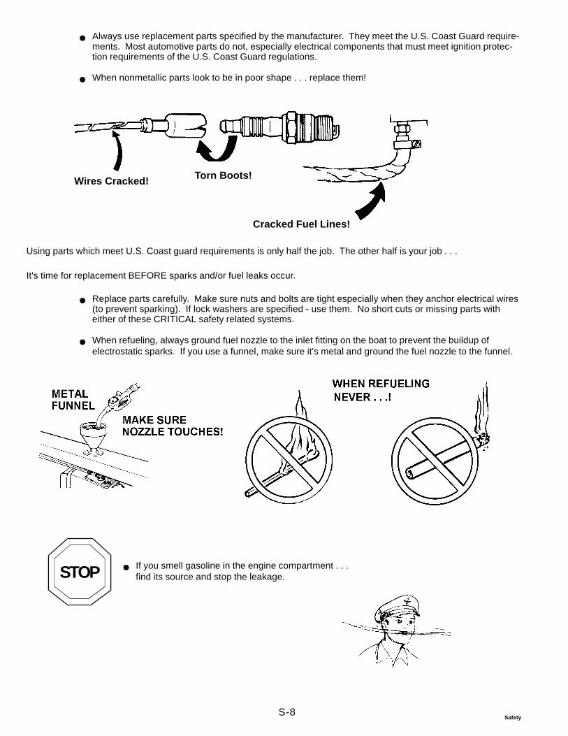
S-8Safety
Always use replacement parts specified by the manufacturer. They meet the U.S. Coast Guard require-ments. Most automotive parts do not, especially electrical components that must meet ignition protec-tion requirements of the U.S. Coast Guard regulations.
When nonmetallic parts look to be in poor shape . . . replace them!
Wires Cracked! Torn Boots!
Cracked Fuel Lines!
Using parts which meet U.S. Coast guard requirements is only half the job. The other half is your job . . .
It's time for replacement BEFORE sparks and/or fuel leaks occur.
Replace parts carefully. Make sure nuts and bolts are tight especially when they anchor electrical wires(to prevent sparking). If lock washers are specified - use them. No short cuts or missing parts witheither of these CRITICAL safety related systems.
When refueling, always ground fuel nozzle to the inlet fitting on the boat to prevent the buildup ofelectrostatic sparks. If you use a funnel, make sure it's metal and ground the fuel nozzle to the funnel.
STOP If you smell gasoline in the engine compartment . . .find its source and stop the leakage.

S-9Safety
Follow "Starting Procedure" outlined in the operator's manual.
Always make sure there are no gasoline fumes in the engine compartment before starting theengine. Open the compartment and use your nose. Don't gamble.
Backfire flame arrestor must be in place and securely attached to the air intake.
Do not alter the backfire flame arrestor.
If loose, damaged, or altered, an engine "backfire" may pass through the flame arrestor assembly into the engine compart-ment. If fumes are present in compartment, fire and explosion could result.

S-10Safety
Summing Up
Now you know some things that can take the joy out of enjoyable boating.
No doubt about it . . . it takes time!
Reading and understanding instructions.
Reading and understanding warnings marked with . . .
Putting parts together correctly . . .
Making correct adjustments . . .
Testing you work.
and making sure
Worn or damaged parts are replaced,
Replaced parts are like originals . . . in every way.
Customer is told of things which need attention . . .
But do you really want the alternative?

S-11Safety
Part B - Marine Products and Safety ofPeople* Who Fix Them
Part A talked about safe boating and how you, the mechanic, can help keep it safe for the boater. But what about you?Mechanics can be hurt while . . .
Servicing boatsServicing sterndrivesTroubleshooting problemsTesting their work
Some items you'll know . . . others you may not.
When Lifting Engines
If hoist is poor shape . . . or too small for the job
Engine may drop suddenly
Make sure shop aids have extra capacity — and keep them in good repair!
When Running Engine with Engine Compartment Cover Removed
The engine compartment cover is a guard. When you remove the cover / guard to work on the engine, remember:
Loose clothing (open shirt sleeves, neckties), long hair, jewelry (rings, watches, bracelets), hands,arms, belts can be caught by moving belts or spinning pulleysHandle high voltage ignition components carefully. They can shock you and may cause you to recoil intomoving parts.
Two people working together on a running engine must look out for each other. Never, ever, hit the key to start theengine before signalling to your partner. (He may be leaning over the engine with his hands on a belt, or a "hot" electri-cal part, near the propeller, etc.)
*Mechanics, technicians, backyard do-it-yourselfers.
DR3471 DR3469

S-12Safety
Exhaust gasses of running engines contain carbon monoxide. . . you can't see it. . . you can't smell it. . .you can't taste it. . . but it's there whenever an engine runs. . . and it's deadly!
When you smell the other gasses in the exhaust, you are inhaling carbon monoxide. Run engines only in well ventilatedareas.
Eyes Need help
Grinding S p r a y e dCleaners,Paints
End of Cables Acid
Chiseling(steel on steel)(Tip: Use plastic or brass type hammers.They don't chip off as easily as steel hammers.)
If spilled or splashed onany part of body..
If solution getsinto eyes. . .Wash. . . and see a Doctor, fast!
Wash with lotsof water. . .
Charging Lead Acid Batteries
Attach and remove these cableswith charger unplugged from 110 volt wallsocket. (Prevents shocks if the chargeris defective.)
Observe correct polarity when con-necting these charger leads.
Always charge in a well ventilatedarea. Charging causes acid solution togive off hydrogen gas through the ventsin the caps. . . Make sure vents are open.If clogged, pressure inside may build. . .battery may explode.
Handling Lead Acid Batteries

S-13Safety
Battery gas is explosive!While charging or discharging,remember. . .
Never yank cables offbattery posts. . . it's a sureway to make lots ofsparks. . .surrounded by battery gas
No SmokingNo FlamesNo Sparks
Don't check battery conditionby placing metal objectsacross posts.
You're sure to make sparksand serious burns arepossible.
After Charging. . .
Shut off charger
Remove charger plug from wall socketThen. . .
Take charger cable off battery posts
Gasoline explodes easily and violently when mixed with air
5 PartsGasoline
100 PartsAir
If the air around you is quiet . . . the pilot light inthe heater mayignite the heavy fumesbefore your nose eversmells the fumes . .
Gasoline! Handle With Care
When you smell any odor of gasoline,explosion is possible
Gasoline fumes are heavier than air and will sinkto the lowest point in the boat or room,and will stay there. . . waiting
Store in sturdy,sealed gas can. . .and . . .keep outside
What Can you Do?
Store properly . . . Fill portable tanks outside boat to prevent spillage in
boat Use fuel for fuel . . . not for a solvent If fumes are smelled (in shop, basement, garage), immediately:
Put out open flames, cigarettes, sparking devicesWipe up spill or leak; get towels, rags outside fastCheck lowest area for fumes; open doors or win-dows

S-14Safety
Read the container label. It tells you . . .
"How, and where, to use,""How to give First Aid," and have "recommended" first aid materials on hand- should anemergency arise"How to dispose of can,"
Remember: Little children are very curious and will try to taste everything, so . . .
. . . yummmmmmmmmmm Keep containers awayfrom children
Know items in and around repair area which can ignite gasoline fumes . . . Control them if fumes are smelled.
Matches, cigarettes, torches, weldersElectric motors (with unsealed cases)Electric generators (with unsealed cases)Light switchesAppliance pilot lights (furnace, dryer, water heater)?????????
How many of these are in your area?
Hazardous Products


����
����
���
���
���
�
���������������� ������������������������� �����
��� � ���������� ������������
�