workshop manual - j/109 class associationj109.org/docs/volvo_d1-30_workshop_manual.pdf · 3...
TRANSCRIPT

Workshop manualGroup 21-26, 30
A
2(0)
D1-13, D1-20, D1-30, D2-40


1
Group 21–26, 30
Marine diesel engines
D1-13 A, D1-20 A, D1-30 A, D2-40 A
Contents
Safety information ............................................................ 3General information ......................................................... 6
About this Workshop Manual ......................................... 6Spare parts ..................................................................... 6Certified engines ............................................................ 6
Repair instructions .......................................................... 7Our common responsibility ............................................ 7Torque ............................................................................ 7Torque-angle tightening ................................................. 8Lock nuts ........................................................................ 8Strength classes ............................................................. 8Sealant ........................................................................... 8
Safety rules for fluorocarbon rubber ................................. 9
Special tools ................................................................... 10
Design and functionGroup 21 Short block
Engine, general ............................................................ 12Engine block ................................................................ 16Cylinder head ............................................................... 16Crankshaft .................................................................... 17Timing gear .................................................................. 18Crankcase breather ..................................................... 18
Group 22 Lubrication systemLubrication oil system .................................................. 19Oil valves ...................................................................... 20Oil pump ....................................................................... 20Oil filter ......................................................................... 20
Group 23 Fuel systemFuel system .................................................................. 21Injection pump .............................................................. 22Centrifugal regulator .................................................... 22Injectors ........................................................................ 22Fuel filter ....................................................................... 23Feed pump ................................................................... 23
Group 26 Cooling systemCooling system ............................................................ 24Thermostat ................................................................... 25Heat exchanger ............................................................ 25Sea water pump ........................................................... 25Coolant pump ............................................................... 25
Group 30 Electrical systemElectrical system .......................................................... 26Alternator ...................................................................... 27Starter motor ................................................................. 27Distribution box ............................................................ 27Electrical components .................................................. 28
Repair instructionsWhen working with chemicals, fuel and lubricating oil 29Before working in a boat .............................................. 29Before lifting the engine ............................................... 29Condition test, engine .................................................. 30Compression test ......................................................... 30Actions after lifting the engine ...................................... 30Cooling system, draining ............................................. 31Engine oil, draining/changing ...................................... 31Engine fixture, fixing ..................................................... 32
Group 21 Short blockShort block, disassembly ............................................. 33Inspection, component change, overhaul andassembly of the short block engine ..................... 37-53Inspecting the engine block ......................................... 37Inspecting the cylinder head ........................................ 38Changing the valve seats ............................................ 38Grinding of valve and valve seats ................................ 39Checking the valve guides .......................................... 40Renovating the rocker arm mechanism ....................... 41Inspecting the crankshaft ............................................. 42Inspection of the and crankshaft bushing andcrankshaft journal ......................................................... 42Inspection of main and big end bearings. ................... 42Checking the big end bearing clearance: ................... 43Piston ring inspection and fits ...................................... 44Inspection and measurement of piston and cylinderbore. ............................................................................. 44Inspecting the con rod .................................................. 45Changing the gudgeon pin bushing ............................ 45Assembling the piston, piston rings and con rod. ........ 46Camshafts and valve lifters, inspection ....................... 47Measuring the camshaft ............................................... 47Installing the crankshaft ............................................... 49Installing the piston in the cylinder and the oil pan ..... 50Installing the timing gear and injection pump .............. 51Flank clearance, checking ........................................... 52Measuring the piston height, installing the cylinderhead and other assembly ............................................ 53
Continued on next page

Table of contents
2
© 2006 AB VOLVO PENTAWe reserve the right to make modifications without prior notice. Printed on environmentally compatible paper
Cylinder head, removal ................................................ 56Valves, removing .......................................................... 58Valves, installation ....................................................... 58Cylinder head, installation ........................................... 59Timing gear, removing ................................................. 61Timing gear, installation ............................................... 64Pistons, removal ........................................................... 67Big end bearing, change ............................................. 68Pistons, change ............................................................ 68Pistons, installation ...................................................... 69Crankshaft, remove ...................................................... 70Main bearings, change ................................................ 71Crankshaft, assembly ................................................... 73Flywheel, change ......................................................... 74Crankcase seal rear, change ....................................... 75Crankshaft seal, front, change ..................................... 76Valves, adjustment ....................................................... 77Drive belt, change ........................................................ 79
Group 22 Lubrication systemOil pump bearing, changing ........................................ 80
Group 23 Fuel systemInjection pump, changing ............................................. 81Injectors, changing ....................................................... 83Injectors, testing ........................................................... 85Injectors, check ............................................................ 85Setting the engine speed ............................................. 86Feed pump, changing .................................................. 87Hand pump, changing ................................................. 88Fuel system, venting .................................................... 89
Group 26 Cooling systemCoolant ......................................................................... 90Pressure valve in filler cap, checking .......................... 91Fault causes, cooling system ....................................... 91Thermostat, change ..................................................... 92Heat exchanger, cleaning ............................................ 93Heat exchanger/exhaust manifold, changing .............. 94Seawater pump, impeller change ................................ 95Sea water pump, change ............................................. 96Coolant pump, change ................................................ 97
Group 30 Electrical systemAlternator, changing ..................................................... 98Starter motor, changing ................................................ 99
Wiring diagram ............................................................. 100
Technical data .............................................................. 103
References to Service Bulletins ................................. 116

3
IntroductionThis workshop manual contains technical data, de-scriptions and repair instructions for the Volvo Pentaproducts or product versions noted in the table of con-tents. Check that you have the correct WorkshopManual for your engine.
Read the available safety information, “General infor-mation” and “Repair instructions” in the workshopmanual before you start to do any service work.
ImportantIn this book and on the product you will find the follow-ing special warning symbols.
WARNING! Warns for the risk of personal injury,major damage to product or property, or seriousmalfunctions if the instruction is ignored.
IMPORTANT! Is used to call attention to thingswhich could cause damage or malfunctions toproduct or property.
NOTE! Is used to call attention to important informa-tion, to facilitate work processes or operation.
Below is a summary of the risks involved and safetyprecautions you should always observe or carry outwhen operating or servicing the engine.
Make it impossible to start the engine by cuttingsystem current with the main switch(es)and lockit (them) in the off position before starting ser-vice work. Set up a warning notice by the helmstation.
As a general rule all service operations must becarried out with the engine stopped. Sometasks, such as adjustments, need the engine tobe running, however. Approaching an enginewhich is operating is a safety hazard. Remem-ber that loose clothing or long hair can fasten inrotating parts and cause serious personal injury.
If work is done adjacent to a running engine, acareless movement or a dropped tool can leadto personal injury in the worst case.Take care to avoid contact with hot surfaces(exhaust pipes, Turbocharger, air intake pipe,starter heater etc.) and hot fluids in pipes andhoses in an engine which is running or has justbeen stopped. Reinstall all protective parts re-moved during service work before starting theengine.
Check that the warning or information labels onthe product are always clearly visible. Replacelabels which have been damaged or paintedover.
Never start the engine without installing the aircleaner filter. The rotating compressor turbine inthe turbocharger can cause severe injury. For-eign objects entering the intake ducts can alsocause mechanical damage.
Never use start spray or similar products as astarting aid. They may cause an explosion inthe inlet manifold. Danger of personal injury.
Avoid opening the coolant filling cap when theengine is hot. Steam or hot coolant can sprayout and the system pressure will be lost. Openthe filler cap slowly, and release the pressure inthe cooling system if the filling cap or tap has tobe opened, or if a plug or coolant hose has to beremoved when the engine is hot. Steam or hotcoolant might spray out in an unexpected direc-tion.
Hot oil can cause burns. Avoid skin contact withhot oil. Ensure that the lubrication system is notunder pressure before carrying out any work.Never start or operate the engine with the oil fill-er cap removed, otherwise oil could be ejected.
Stop the engine and close the sea cocks beforedoing any work on the cooling system.
Only start the engine in a well- ventilated area.When operated in a confined space, exhaustfumes and crankcase gases must be ventilatedfrom the engine bay or workshop area.
Always use protective glasses or goggles whencarrying out work where there is a risk of splin-ters, grinding sparks, acid splashes or whereother chemicals are used. Your eyes are ex-tremely sensitive, injury could cause blindness!
Safety information

Safety information
4
Batteries must never be exposed to openflames or electric sparks. Never smoke close tothe batteries. The batteries generate hydrogengas when charged, which forms an explosivegas when mixed with air. This gas is easily ignit-ed and highly volatile. A spark, which can becaused by incorrect battery connection, cancause a single spark which is sufficient tocause an explosion with resulting damage. Donot move the connections when you attempt tostart the engine (risk of arcing), and do notstand and lean over one of the batteries.
Always ensure that the Plus (positive) and Mi-nus (negative) battery cables are correctly in-stalled on the corresponding terminal posts onthe batteries. Incorrect installation can result inserious damage to the electrical equipment. Re-fer to the wiring diagram.
Always use protective goggles when chargingand handling the batteries. Battery electrolytecontains sulfuric acid which is highly corrosive.Should the battery electrolyte come into contactwith unprotected skin wash off immediately us-ing plenty of water and soap. If you get batteryacid in your eyes, flush at once with a generousamount of water, and get medical assistance atonce.
Turn the engine off and turn off the power at themain switch(es) before carrying out work on theelectrical system.
Clutch adjustments must be carried out with theengine stopped.
The existing lugs on the engine/reversing gearshould be used for lifting the assembly.Always check that the lifting devices are in goodcondition and that they have the correct capaci-ty for the lift (the weight of the engine plus thereversing gear and extra equipment).The engine should be lifted with a customized oradjustable lifting boom for safe handling and toavoid damaging components on top of the en-gine. All chains or cables should be parallel toeach other and should be as square as possibleto the top of the engine.If other equipment connected to the engine hasaltered its center of gravity, special lifting devic-es may be needed to obtain the correct balanceand safe handling.Never do any work on an engine which justhangs from a lifting device.
Avoid getting oil on your skin! Repeated expo-sure to oil or exposure over a long period can re-sult in the skin becoming dry. Irritation, drynessand eczema and other skin problems can thenoccur. Used oil is more dangerous than fresh oilfrom a health aspect. Use protective gloves andavoid oil soaked clothes and rags. Wash regu-larly, especially before eating. There are specialskin creams which counteract drying out of theskin and make it easier to clean off dirt afterwork is completed.
Most chemicals intended for the product (e.g.engine and transmission oils, glycol, petrol (gas-oline) and diesel oil) or chemicals for workshopuse (e.g. degreasers, paints and solvents) arehazardous. Read the instructions on the productpackaging with care! Always follow the safetyprecautions for the product (for example use ofprotective mask, glasses, gloves etc.). Makesure that other personnel are not inadvertentlyexposed to hazardous chemicals, for example inthe air. Ensure good ventilation in the workplace. Follow the instructions provided when dis-posing of used or leftover chemicals.
Exercise extreme care when leak detecting onthe fuel system and testing the fuel injector noz-zles. Use eye protection. The jet which comesfrom a fuel injector has very high pressure andconsiderable penetrationability. Fuel can forceits way deep into body tissue and cause severeinjury. Danger of blood poisoning (septicemia).
All fuels, and many chemicals, are flammable.Do not allow naked flame or sparks in the vicini-ty. Petrol (gasoline), some thinners and hydro-gen gas from batteries are extremely flammableand explosive when mixed with air in the correctratio. No smoking! Ensure that the work area iswell ventilated and take the necessary safetyprecautions before starting welding or grindingwork. Always ensure that there are fire extin-guishers at hand when work is being carried out.
Make sure that oil and fuel soaked rags, andused fuel and oil filters are stored in a safeplace. Rags soaked in oil can spontaneously ig-nite under certain circumstances. Used fuel andoil filters are polluting waste and must be hand-ed to an approved waste management facilityfor destruction, together with used lubrication oil,contaminated fuel, paint residue, solvents, de-greasers and wash residue.
Safety information
5
Remember the following when washing with apower washer: Never aim the water jet at seals,rubber hoses or electrical components. Neveruse a power washer for engine cleaning.
Only use the fuels recommended by Volvo Pen-ta. Refer to the Instruction Book. Use of fuelsthat are of a lower quality can damage the en-gine. On a diesel engine, poor quality fuel cancause the control rod to bind and the engine tooverrev with resulting risk of damage to the en-gine and personal injury. Poor fuel can also leadto higher maintenance costs.
Never work alone when removing heavy enginecomponents, even when using lifting devicessuch as locking tackle lifts. When using a liftingdevice two people are usually required to do thework, one to take care of the lifting device andanother to ensure that components are liftedclear and not damaged during the lifting opera-tions.When you work aboard a boat, always makesure that there is enough space for disassemblywhere you are working, with no risk of personalinjury or material damage.
Components in the electrical and fuel systemson Volvo Penta products have been designed tominimize the risks of explosion and fire. The en-gine must not be run in areas where there areexplosive materials.

6
About this Workshop ManualThis workshop manual contains technical data, de-scriptions and repair instructions for the following ma-rine diesel engines: D1-13, D1-20, D1-30 and D2-40.
The engine designation and number are noted on thenumber plate and engine decal. The engine designa-tion and number must always be given in all corre-spondence about any product.
The Workshop Manual is produced primarily for theuse of Volvo Penta workshops and service techni-cians. This assumes that people who use the Manualhave basic knowledge of marine drive systems andcan do the tasks of a mechanical or electrical natureassociated with the trade.
Volvo Penta constantly improves its products, so wereserve the right to make modifications without priornotification. All information in this manual is based onproduct data which was available up to the date onwhich the manual was printed. Any material changesintroduced into the product or service methods afterthis date are notified by means of Service Bulletins.
Spare partsSpare parts for electrical- and fuel systems are sub-ject to various national safety requirements, such asU.S. Coast Guard Safety Regulations. Volvo PentaOriginal Spare Parts meet these specifications. Anydamage, occasioned by use of non-original VolvoPenta spares for the product, will be not be compen-sated by the warranty offered by Volvo Penta.
General information
Certified enginesWhen doing service and repair on emission certi-fied engines, it is important to be aware of the fol-lowing:
Certification means that an engine type has beenchecked and approved by the relevant authority. Theengine manufacturer guarantees that all engines madeof the same type are equivalent to the certified en-gine.
This makes special demands on service and repairwork, as follows:
● Maintenance and service intervals recommendedby Volvo Penta must be complied with.
● Only Volvo Penta original spares may be used.
● Service to injection pumps, pump settings and in-jectors must always be done by an authorizedVolvo Penta workshop.
● The engine must not be converted or modified,except for the accessories and service kits whichVolvo Penta has approved for the engine.
● No installation changes to the exhaust pipe andengine air inlet ducts may be done.
● No seals on the engine may be broken by unau-thorized persons.
The general advice in the instruction book about oper-ation, care and maintenance applies.
IMPORTANT! Delayed or inferior care/mainte-nance, and the use of non-original spares, partsmeans that AB Volvo Penta can no longer be re-sponsible for guaranteeing that the engine com-plies with the certified version.
Damage and/or costs which arise from this willnot be compensated by Volvo Penta.
7
The working methods described in the Workshop Man-ual apply to work carried out in a workshop. For thisreason, the engine is lifted out of the boat and mount-ed on an engine support. Unless otherwise stated, re-conditioning work which can be carried out with theengine in place follows the same working method.
The warning signs which occur in the workshop manu-al (please refer to “Safety information” for their mean-ings)
WARNING!
IMPORTANT!
NOTE!
are not comprehensive in any way, since we can notof course foresee everything, because service work isdone in highly varying circumstances. For this reason,all we can do is to point out the risks which we believecould occur due to incorrect work in a well-equippedworkshop, using work methods and tools tested byus.
All operations described in the Workshop Manual forwhich there are Volvo Penta Special Tools availableassume that these tools are used when carrying outthe repair. Volvo Penta Special Tools have been spe-cifically developed to ensure the most safe and ratio-nal working methods possible. It is therefore the re-sponsibility of anyone using other tools or other work-ing methods than we recommend to determine thatthere is no risk of personal injury or mechanical dam-age or malfunction as a result.
In some cases special safety precautions and user in-structions may be required in order to use the toolsand chemicals mentioned in the Workshop Manual.These rules must always be observed, so there are nospecial instructions about this in the workshop manu-al.
By following these basic recommendations and using-using common sense it is possible to avoid most ofthe risks involved in the work. A clean workplace anda clean engine will eliminate many risks of personalinjury and engine malfunction.
Above all, when work on fuel systems, lubricationsystems, induction systems, turbocharger, bearingcaps and seals is done, it is extremely important thatno dirt or other kinds of foreign particles are able toget in, since this would otherwise cause malfunctionsor shortened repair life.
Our common responsibilityEach engine consists of many interacting systemsand components. The deviation of one componentfrom the technical specification can dramatically in-crease the environmental impact caused by an other-wise good engine. For this reason, it is important thatthe specified wear tolerances are observed, that sys-tems which are adjustable are correctly adjusted andthat Volvo Penta Original Spares are used for the en-gine. The stated service intervals in the MaintenanceSchedule must be observed.
Some systems, such as the components in the fuelsystem, require special expertise and special testingequipment for service and maintenance. For environ-mental reasons etc., some components are sealed atthe factory. It is only permissible to work on sealedcomponents if you are authorized to do such work.
Remember that most chemical products, incorrectlyused, damage the environment. Volvo Penta recom-mends the use of biodegradable degreasers wheneverengine components are de-greased, unless otherwisespecified in the workshop manual. When workingaboard a boat, be careful to ensure that oils, washresidue etc. are processed for destruction, and are notinadvertently discharged with bilge water into the envi-ronment.
TorqueThe tightening torque for vital fasteners, which shouldbe tightened with a torque wrench, are listed in “Tech-nical Data: Special tightening torques” and noted inthe job descriptions in the book. All torque specifica-tions apply to clean screws, screw heads and matingfaces. Torque data stated apply to lightly oiled or drythreads. If lubricants, locking fluids or sealants areneeded on a fastener, the type of preparation to beused will be noted in the job description. For fastenerswhere specific torque values are not given, please re-fer to “Technical data, General Tightening Torque”.
Repair instructions

Repair instructions
8
Torque-angle tightening
In torque/angle tightening, the fas-tener is tightened to the specifiedtorque, and tightening then contin-ues through a pre-determined angle.Example; for 90° angle tightening,the fastener is tightened a further1/4 turn in one sequence, after thespecified tightening torque has beenachieved.
SealantThe sealants and locking fluids noted below shall beused on the engines covered by this manual.
To ensure service work is correctly carried out it is im-portant that the correct sealant and locking fluid typeis used on the joint where the agents are required.
In this Volvo Penta Workshop Manual the user willfind that each section where these agents are appliedin production states which type was used on the en-gine.
When sealants and locking fluids are used, it is impor-tant that the surfaces are free from oil, grease, paintand rust-protection, and that they are dry. Always fol-low the manufacturer’s instructions use regarding tem-perature range, curing time and any other instructionsfor the product,
Two different basic types of agent are used on the en-gine. These are:
RTV preparations (Room Temperature Vulcanizing).Used for gaskets, sealing gasket joints or coatinggaskets. RTV is visible when a part has been disas-sembled; old RTV must be removed before resealingthe joint.
The following RTV preparations are used on the en-gine:Volvo Penta sealant (cartridge 0.31 l, part. no.1161231-4, or tube 20 g., part. no. 1161277-7) andpart. no. 840879-1 (tube 25 g).
Remove old sealant with denatured alcohol.
Anaerobic agents. These agents cure in the absenceof air. These preparations are used when two solidcomponents, such as two cast components, are fittedtogether without a gasket. Common uses are also tolock and seal plugs, stud threads, taps, oil pressuremonitors etc.
Hardened anaerobic preparations are glassy and forthis reason, the preparations are colored to makethem visible.Hardened anaerobic preparations are highly resistantto solvents, and old compound must be removed me-chanically. On re-assembly, it is important to de-grease components carefully first, wipe off and applynew sealant in accordance with the instructions.
The following anaerobic preparations are used on theengines:Volvo Penta thread locking fluid (part. no. 1161053-2)and sealing compound (part. no. 1161059-9).
Strength classesScrews and nuts are sub-divided into differentstrength classes. The classification is shown by amarking on the screw head. Markings of a higher num-ber indicate stronger material. For example, a screwmarked 10-9 is stronger than one marked 8-8. For thisreason, it is important when fasteners are dismantled,that the screws are put back in the correct placeswhen they are re-installed. If a screw must be re-placed check in the spare parts catalogue to makesure the correct screw is used.
Lock nutsDisassembled locknuts shall not be re-used, theyshall be replaced by new ones, since the locking prop-erties are impaired or lost when the nut is used sever-al times. On locknuts with plastic inserts, such as Ny-lock® , the tightening torque specified in the tablemust be reduced if the Nylock® nut has the same nutheight as a standard fully metallic hexagonal nut. Re-duce the torque by 25% for screw size 8 mm or larger.On Nylock® nuts with higher nut height, where the fullymetallic thread is as high as on a standard hexagonalnut, use the tightening torques in the table.

Repair instructions
9
Safety rules forfluorocarbon rubberFluorocarbon rubber is a common material in sealrings for shafts, and in O-rings, for example.
When fluorocarbon rubber is exposed to high tempera-tures (above 300°C), hydrofluoric acid can beformed, which is highly corrosive. Contact with theskin can result in severe chemical burns. Splashes inyour eyes can result in severe chemical burns. If youbreathe in the fumes, your lungs can be permanentlydamaged.
WARNING! Observe the greatest care in work-ing on engines which might have been exposedto high temperatures, such as overheating dur-ing flame cutting or a fire. Seals must never becut with a flame torch during disassembly, orburned in uncontrolled circumstances after-wards.
● Always use chloroprene rubber gloves (gloves forchemicals handling) and goggles.
● Handle the removed seal in the same way as cor-rosive acid. All residue, including ash, can behighly corrosive. Never use compressed air toblow anything clean.
● Put the remains in a plastic container, seal it andapply a warning label. Wash the gloves under run-ning water before removing them.
The following seals are most probably made from fluo-rocarbon rubber:
Seal rings for the crankshaft, camshaft, drive shafts.
O-rings, regardless of where they are installed. O-rings for cylinder liner sealing are almost always madeof fluorocarbon rubber.
Please note that seals which have not been ex-posed to high temperature can be handled normal-ly.
NOTE! As the illustrations in the service literature refer toseveral engine variants, certain details may differ from anyparticular engine. The essential information in the illustra-tions is always correct, however.

10
Special tools
885 023
885 498
885 510885 820
981 2519
998 8539
885 822
998 9876
856 927
885 252
856 927 Measurement putty, for measuring main and big endbearing clearance.
885 023 Valve spring compressor
885 252 Adapter for testing compression pressure
885 484 Adapter for testing compression pressure
885 498 Pressure foot, for valve compressor
885 510 Protective caps, fuel system
885 820 Puller, for pulley
885 822 Magnetic pen
885 824 Engine fixture
981 2519 Multimeter
998 6485 Equipment stand
998 8539 Compression tester
998 9876 Dial gauge
885 484
885 824
998 6485
Special tools
11
9995919
999 9737
999 6662
999 9179
384 9639
384 9640999 9772
999 9696
999 2520
999 9683
9995192
999 2520 Equipment stand
999 5192 Holder, dial gauge, piston height measurement
9995919 Puller, seals
999 6662 Pressure testing device
999 9179 Spanner for removing fuel/oil filters
999 9684 Dial gauge
999 9696 Magnetic stand
999 9737 Fixture cylinder, for fixture 885 824
999 9772 Injector tester
384 9639 Installation tool for oil pump shaft (D1-13, D1-20)
384 9640 Installation tool for oil pump shaft (D1-30, D2-40)

12
Design and function
Group 21 Short block
Engine, generalThe D1-13, D1-20, D1-30 and D2-40 are four cyclemarine diesel propulsion engines. They all have twovalves per cylinder, a high-mounted camshaft in theengine block and a mechanical injection pump.
The D1-13 is an in-line two cylinder engine with a totalswept volume of 0.51 liter. The D-20 and D1-30 are in-line three cylinder engines with total swept volumes of0.76 and 1.13 liter respectively. The D2-40 is an in-line four cylinder engine with a total swept volume of1.51 liter.
The D1-13 and D1-20 engines have identical pistonswith the same dimensions. The D1-30 and D2-40 en-gines have different pistons, but of common dimen-sions.
The engines are lubricated by a pressure lubricationsystem, in which an oil pump supplies oil under pres-sure to all lubrication points.
Fresh water cooling uses a thermostatically controlledsea-water cooled heat exchanger. The sea waterpump is operated by a gear train.
The crankshaft operates the coolant pump and alter-nator via a drive belt.
D1-30 engine
Group: 21 Short block Design and function
13
D1-13 A with MS10A reversing gear
D1-20 A with MS10A reversing gear

Design and function Group: 21 Short block
14
D1-30 A with MS15A reversing gear
D2-40 A with 130S sailboat drive

Group: 21 Short block Design and function
15
Engine
Product designation (1) .......................................................................................................
Serial number (2) .................................................................................................................
Product number (3) .............................................................................................................
Certification number (4) .......................................................................................................
S - drive/Reversing gear
Product designation (5) ........................................................................................................
Serial number (6) ..................................................................................................................
Product number (7) ..............................................................................................................
Gear ratio (8) ........................................................................................................................
Propeller designation ............................................................................................................
Engine plate
Engine and transmission decal
S - drive and reversing gear sign
XXXXXX (7)
XXX (5)
XXXXXXXXXX (6)
XX (8)
D1-30, D2-40 D1-13, D1-20
Location of information decals and type platesThere are type plates on the engine and transmission, marked with identification numbers. This information mustalways be used a reference when spare parts are ordered. The appearance and location of the type plates isshown below. The figures in brackets refer to the location of the identification number on the type plate.

Design and function Group: 21 Short block
16
Engine blockThe engine block is cast in one piece, from speciallyalloyed cast iron. The camshaft is located in the en-gine block.
The D1-13 has two cylinder bores, the D1-20 andD1-30 have three and the D2-40 has four.
The D1-13 and D1-20 have the same dimension percylinder. The D1-30 and D2-40 have a larger, commondimension per cylinder.
None of the engines have cylinder liners. The cylinderwalls are machined directly in the engine block.
SumpThe sump is located under the engine block and ismade from pressed sheet metal. There is an oil drainpipe under the sump.
CamshaftThe camshaft has lobes which operate the valves, thefuel pump and the injection pump. The camshaft isdriven by the crankshaft and gear wheels, via the oilpump gear wheel.
Cylinder headThe cylinder head (1) is made from specially alloyedcast iron.
The cylinder head has one inlet and one exhaust valveper cylinder. These are operated by the camshaft viavalve lifters and push rods. The valves have replace-able seats.
An injector is installed in the combustion chamber ofeach cylinder. There is one glowplug per cylinder.
Rocker arm coverThe rocker arm cover (2) is made of aluminum and islocated above the cylinder head. The valve mecha-nism is installed underneath the cover. Pressurizedlube oil passes via an external pipe to the rocker armshaft, and then lubricates the rocker arms and valves.
Valve coverThe valve cover (3) is made of aluminum and is locat-ed above the rocker arm cover. The valve cover hastwo internal sections, of which one leads inlet air downinto the cylinder head via an inlet. The other sectioncontains the crankcase ventilation valve.
1
2
3

Group: 21 Short block Design and function
17
CrankshaftThe crankshaft (1) is supported by main bearings (2).The thrust bearing is integrated in the rear main bear-ing cap (3). The crankshaft is statically and dynami-cally balanced, and has induction hardened bearingsurfaces. At the front end, where the gear wheel (4) forthe timing gear and the pulley (5) for the alternator andcoolant pump are located, the crankshaft has a groovefor a Woodruff key. At the rear of the crankshaft, thereis a flange (6) to which the flywheel is attached.
Main and big end bearingsThe main and big end bearings (7) consist of steel-shells lined with bearing metal. The bearings are preci-sion made and are ready to be installed.
Con rodsThe con rods (8) have an I-section. The small end isdrilled for gudgeon pin lubrication.
PistonsThe pistons (9) are made of light metal alloy. Theyhave three piston rings (10). Two piston rings are com-pression rings and one is an oil scraper ring.
6
73
5
1
2
4
8
10
9

Design and function Group: 21 Short block
18
Timing gearThe timing gear consists of cylindrical gear wheelswith helical teeth, located at the front of the engineblock. A timing gear cover (1) provides complete pro-tection for the timing gear.
The camshaft (2) and sea water pump (3) are drivenby the crankshaft gear (4), via an idler wheel (5). Theengine’s lubrication pump is integral with the idlergear, and is driven by it. The regulator weights (6) arehung at the front of the camshaft drive and adjust theinjection pump via a mechanism in the timing gearcover.
Crankcase breatherThe crankcase ventilation is sealed and pressure con-trolled with a valve and spring located in the valvecover. When the gas pressure is higher, the valveopens and directs the crankcase gases into the inletsection, for combustion in the cylinders.
6
5
1
2
4
3

Group: 22 Lubrication system Design and function
19
Group 22 Lubrication system
Lubrication oil systemThe engines are provided with a complete pressure lu-brication system. The lube oil pump is a gear wheelpump, and is driven by the crankshaft. The lube oil islead through an external pipe to the valve mechanism.
The lube oil system has a reduction valve which limitsthe maximum oil pressure in the engine.
The oil filter is a full-flow filter, with bypass valve.
1. Oil filter2. Oil pressure monitor3. Pressure reduction valve4. Inlet pipe with strainer5. Main oil duct6. Oil pump7. Oil supply pipe (outer) to valve mechanism8. Crankcase ventilation, valve
1
2
3 4 5
6
7
8
Design and function Group: 22 Lubrication system
20
Oil valvesThe lubrication pressure is limited by a reductionvalve (1). The valve is installed in the lubrication sys-tem, just upstream of the oil filter (2). The valve opensat high pressure and allows the oil to flow back intothe sump.
The D1-13 and D1-20 engines have a reduction valvewhich opens in the interval from 352-448 kPa. On theD1-30 and D2-40 engines, the valve opens in the inter-val from 304-500 kPa.
A bypass valve located on the oil filter opens if the re-sistance in the filter rises abnormally high. Oil supplyto the lubrication points is ensured in this way, even ifthe filter is blocked, but the oil is no longer cleaned.
Oil filterThe purpose of the oil filter is to remove contamina-tion from the oil. The filter is a full flow filter, whichmeans that all the oil is filtered before it is forced outinto the lubrication system.
Filter insert is a folded paper filter.
There is a bypass valve (1) at the base of the filter,which opens and allows oil to flow past the filter if thefilter insert should become blocked.
When the filter has been in use for a pre-determinedtime, it must be replaced by a completely new filter.
1. Circlip2. Spring washer3. Spring4. Shim5. Cap for oil pump6. Inner rotor7. Idler wheel with outer rotor8. Thrust washer
1
2
6
7
3
5
12
4
8
Oil pumpThe lube oil pump is located in the idler wheel in thetiming gear, which also drives it.
The pump is a rotor pump, with an inner rotor and anouter rotor, eccentrically mounted in relation to eachother. The inner rotor has one “tooth” less than theouter rotor.
The function of the pump is that the volume of thespaces between the inner and outer gears increasesand reduces. During the first section of the rotation ofthe inner rotor, the volume increases, a partial vacu-um occurs and oil is sucked into the inlet. After abouta half rotation, the volume is reduced and a pressureoccurs, which forces the oil out through the outlet.
1

Group: 23 Fuel system Design and function
21
Group 23 Fuel system
Fuel systemA mechanical feed pump sucks the fuel up from thefuel tank, possibly through a water separation filter(optional equipment), and the fuel is then forcedthrough the secondary filter to the injection pump.
The injection pump, which is driven by the camshaft,then distributes fuel of specific quantity and timing tothe injectors.
Fuel which returns from the injectors is returned to thebase of the fuel tank. The air in the fuel system canbe transported back to the fuel tank via a connectionbetween the injection pump and the return fuel pipe.
1. Fuel tank2. Pre - filter3. Feed pump4. Fuel filter5. Hand pump6. Injection pump7. Injectors
The fuel is then forced through the injector nozzlesinto a pre-combustion chamber in the cylinder head athigh pressure and then enters the combustion cham-bers in the pistons, where high speed air rotation con-tributes to even combustion. A glowplug in the pre-combustion chamber pre-heats the fuel mixture forcold starting.
The secondary filter in the engine removes contamina-tion which might be left in the fuel, despite the primaryfilter.
1 2
34
6
7
5

Design and function Group: 23 Fuel system
22
Injection pumpThe injection pump is a flange-mounted in-line pumpwhich is located on the engine block. The pump isdriven by cams on the engine’s camshaft, which oper-ates the pump chambers directly.
The injection pump has the same number of pumppistons as the engine has cylinders.
InjectorsThe engines is provided with pintle - type injectors.Each injector basically consists of a nozzle retainerand a nozzle.
When the fuel pressure increases to the set value(opening pressure), the injector needle which is heldpressed against its seat by the compression spring islifted and atomized fuel is injected into the precom-bustion chamber of the engine.
The injector opening pressure is determined by thecompression spring tension, which is adjusted by ad-justment washers.
1. Injector nut 6. Adjustment washers2. Injectors 7. Injector holder3. Joining piece 8. Washer4. Compression screw 9. Nut5. Spring
12
3 45 6
78
9
Centrifugal regulatorThe regulator is mechanical, and uses regulator-weights for engine speed sensing. It is mounted onthe front of the camshaft gear, which also drives it.
The regulator weights operate the injector pump con-trol rod via the regulation sleeve, a lever and a regula-tor arm. Engine speed is regulated across the en-gine’s entire speed range, from low idle to high idle (allspeed type).

Group: 23 Fuel system Design and function
23
Feed pumpThe feed pump is mounted on the outside of the en-gine block and is driven by an eccentric on the rear ofthe camshaft.
Fuel filterThe fuel filter (1) is of the disposable type. The filterinsert is a paper filter.
The fuel filter is located in a bracket (2) together witha hand pump (3) and vent screw (4).
1
243

Design and function Group: 26 Cooling system
24
Group 26 Cooling system
1. Sea water, inlet2. Sea water filter3. Sea water pump4. Seawater, outlet5. Coolant pump6. Expansion tank7. Heat exchanger/exhaust manifold8. Thermostat9. Open thermostat - circulation10. Closed thermostat - circulation
General
The engine is fresh water cooled and has a sealedcooling system with expansion tank. The system issubdivided into two circuits.
In the inner circuit, the fresh watersystem, the coolantis circulated by a coolant pump which is driven via abelt from the crankshaft pulley.
The fresh water circuit operates under a certainamount of excess pressure, which reduces the risk ofboiling if the temperature rises too high. If the pres-sure becomes higher than normal, a pressure valveopens in the filler cap on the expansion tank.
2
4
1
3
7
5
6
9
10 8
The coolant temperature is regulated by a thermostat.When the engine is cold, a thermostat directs thecoolant round an internal circuit in the engine. Whenoperating temperature begins to be reached, the cool-ant is progressively directed out through the entireheat exchanger, where the surplus heat is removed.
In the outer circuit, the sea water system, sea wateris forced through by a gear-wheel driven pump withrubber impeller.
The sea water system cools the engine’s heat ex-changer. The sea water is returned together with theexhaust gas, via a connection in the exhaust bend.
Group: 26 Cooling system Design and function
25
ThermostatThe engine is equipped with a thermostat whose sen-sor body contains wax.
When the engine is cold, the thermostat keeps thepath to the heatexchanger closed. Coolant then pass-es through a by-pass pipe, back directly to the suctionside of the pump. As the engine warms up, the vol-ume of the wax increases and the thermostat progres-sively opens the passage to the heat exchanger, atthe same time as the by - pass channel is closed.
Please refer to the “Technical Data” chapter for open-ing temperatures.
The thermostat is located in a housing which is inte-grated in the heat exchanger and exhaust manifold.
Coolant pumpThe coolant pump is mounted on the engine block andis driven by the crankshaft by means of a drive belt.
Sea water pumpThe sea water pump is a rubber impeller type pump,and is mounted on the front of the engine. The pumpis driven from the engine’s timing gear system andforces cooling water out to the heat exchanger on theengine.
The impeller (pump wheel) is made of rubber, and isreplaceable.
NOTE! The impeller will be damaged if the pump isrun dry.
Heat exchangerThe heat exchanger is located in a housing which isintegrated with the exhaust manifold and thermostat.
Sea water passes through the heat exchanger matrixand transfers heat from the internal cooling circuit inthe engine (fresh water system) to the outer circuit(sea water). When the thermostat has not yet opened,the coolant is lead through a short, uncooled passagein the heat exchanger and back to the engine.

Design and function Group: 30 Electrical system
26
Group 30 Electrical system
GeneralThe engines have an alternator which supplies electriccurrent of 115 A. System voltage is 12 V and theelectrical system is single-pole.
The electrical system contains sensors for monitoringthe engine coolant temperature and oil pressure. Adistribution box contains a circuit breaker, and thereare two relays under the heat exchanger.
1. Glow plugs2. Stop solenoid3. Coolant temperature monitor4. Coolant temperature sensor5. Distribution box6. Circuit breaker7. Starter relay8. Glowplug relay9. Charge sensing resistor10. Starter motor11. Alternator12. Oil pressure monitor13. Engine speed sensor
2 3
11
5
101312
4
17, 8, 9
6

Group: 30 Electrical system Design and function
27
AlternatorThe alternator provides alternating current (14V/115A).
The voltage regulator on the alternator is provided witha sensor system.
The sensor system compares the charge voltage be-tween the alternator terminals, B+ and B-, with thevoltage across the battery positive and negative termi-nals. The voltage regulator then compensates for anyvoltage drop in the cables between the alternator andthe batteries, by increasing the charge voltage sup-plied by the alternator as necessary.
When delivered from Volvo Penta, the sensor systemis not activated. The connection has probably beendone during engine installation, however.
Starter motorThe starter motor is a DC series motor. The starterpinion is operated by a control solenoid and can beslid axially on the rotorshaft.
The starter motor has a reduction gear, which makesit possible to obtain greater torque.
The starter motor power depends on the engine it isfitted to, please refer to the table below.
D1-13, D1-20 0.8 kWD1-30 1.1 kWD2-40 1.4 kW
Distribution box
Circuit breakerA 16 A circuit breaker protects the electrical systemand cuts the current if overloaded.
If it has tripped, the electrical system is re-connectedby pressing the button on the circuit breaker in thedistribution box. Always first investigate the reason forthe overload.
RelaysThe starting and glowplug functions are each con-trolled by a switching relay. These relays are identicaland are thus mutually interchangeable. They are locat-ed in the distribution box.
Charge sensing resistorThe charge sensing resistor has a value of 33 Ohm/9 W.
Design and function Group: 30 Electrical system
28
Electrical components
Lube oil pressure monitor - alarmContact type: Normally open. The contacts close ifthe lube oil pressure in the engine falls below 0.5±0.15 bar.
The closing pressure should be checked with fallingpressure.
Coolant temperature monitor - alarmContact type: Normally open. The contacts close ifthe coolant temperature exceeds:
D1-13, D1-20 105oC ± 2oCD1-30, D2-40 110oC ± 2oC
The switching point should be checked with risingtemperature.
Coolant temperature sensorResistance testing, measured with the sensor im-mersed down to the hex head screw for three minutesin circulating fluid, with system current connected.
Temp. 60oC: 134.0 ±13.5 Ω (±4oC)
90oC: 51.2 ±4.3 Ω (±4oC)
100oC: 38.5 ±3.0 Ω (±4oC)
Engine speed sensorThe sensor is located on the flywheel housing anduses inductance to give engine speed informationwhich changes with the speed of the engine.
Stop solenoidThe stop solenoid is an electrical stopping devicewhich shuts off fuel supply at the injection pump.
Glow plugsOne glowplug per cylinder is installed in the cylinderhead. All glowplugs are electrically connected by abusbar.
The glowplugs heat the fuel mixture during starting.

29
Repair instructions
Group 21 Short block
GeneralA condition test should be done before each majorservice activity, if possible, to determine the generalcondition of the engine and discovery any concurrentfault causes. A condition test requires the engine tobe run, so this should be done before the engine orany engine components are disassembled.
Please refer to “Condition test, engine”.
When working with chemicals,fuel and lubricating oil
IMPORTANT! Always use protective gloves forwork which includes contact with oil, fuel etc.
Constant skin contact with engine oil can bevery harmful.
Before working in a boat1 Turn the main switch off.
2 Clean the outside of the engine.
NOTE! Make sure that wash residue is collectedfor destruction and does not inadvertently end upin the water. Also refer to the warning text under“Actions after lifting the engine”.
3 The work includes the following actions on thecooling system: Close the sea cocks and drainthe coolant from the sea water and fresh watersystems.
WARNING! Make sure that all sea water inletsare securely closed, so that water can not findits way in during disassembly of cooling systemsub-components.
Before lifting the engine
Boat removed from the water
1 Turn the battery isolator off, undo the battery con-nections on the starter motor.
2 Remove the connector for the engine cables tothe instruments.
3 Remove the sea water connections/cool keelingconnection.
4 Remove the exhaust pipe.
5 Close the fuel taps. Remove the fuel connections.
6 Remove the throttle and gear shift cables.
7 Undo the propeller shaft from the reversing gear.Undo the engine mounting pads from the bed andlift the engine out. Use the lifting lugs (1) on theengine.

Repair instructions Group: 21 Short block
30
Actions after lifting the engine
1 Clean the engine.
IMPORTANT! Remember the following whenwashing with a power washer: Be extremelycareful when cleaning, to avoid getting water in-side engine components. When a power washeris used, the water jet must never be aimed atseals, such as shaft seals, joints with gaskets,rubber hoses or electrical components.
2 Drain the engine oil.
3 Remove the reversing gear (as necessary).
Flat Rate: 21035
Condition test, engineCompression testSpecial tools: 885 252, 885 484, 998 8539
A compression test is done, which shows the sealingof the cylinders and valves, to assess the condition ofthe engine in a simple, reliable manner.
• Warm the engine up, then stop it.
• Remove all the injectors and test each of the cyl-inders in turn.
IMPORTANT! Observe the greatest possiblecleanliness, to avoid getting dirt in the fuel sys-tem. Plug the connections for the disassembledinjectors and fuel pipes.
The compression pressure must be read at normalstarter motor speed.
Low combustion pressure in all cylinders indicatesworn cylinder bores and piston rings. If one cylinderhas lower compression pressure than the others, thereason can be poor valve sealing, broken piston ringsor a damaged cylinder head gasket.
Insert adapter nos. 885 484 and 885 252 in the injec-tor hole.Install a compression gauge 998 8539 in the adapter,and carry out the compression test.

Group: 21 Short block Repair instructions
31
F = Fresh water drain tap
F
F
Cooling system, draining
NOTE! Remove the expansion tank filler cap andclose the hull fitting before draining the cooling sys-tem.
WARNING! Open the pressure cap very careful-ly if the engine is hot. Steam or hot coolant canspray out and cause burns.
1
Connect drain hoses to the taps on the fresh watersystem. Open all drain points.
The sea water system is drained by undoing hoses atthe lowest points of the system.
2Check that all water drains out.
Check whether the installation has any further taps orplugs at the lowest points of the cooling water pipesand exhaust pipe.
3
Close the taps.
4
Pump the bilges out as necessary. Check that noleakage occurs.
Engine oil, draining/changing
Hot engine
1
Connect the suction pipe on the oil drain pump to theoil drain pipe.
Suck the oil into a suitable vessel. The oil can also bedrained after the sump drain plug has been removed.
D1-13 A

Repair instructions Group: 21 Short block
32
Engine fixture, fixing
Drained cooling system and engine oil. Engine re-moved. Right front engine mounting removed.
Special tools: 885 224, 999 9737
Use fixture 885 224 and 999 9737 to fix the engine toengine stand 998 6485. Only fixture 885 224 is neededfor fixing to engine stand 999 2520.
Screw the fixture to the right side of the engine, as inthe illustrations.
D1-20-A
D1-30-A
D1-13-A
D2-40-A
Group: 21 Short block Repair instructions
33
Short block, disassemblyEmpty the oil and water out of the engine. Lift the en-gine with a suitable lifting device. Installing the enginefixture, please refer to “Engine fixture, fixing”.
WARNING! Observe the greatest possiblecleanliness in work on the fuel system. Watchout for fuel spillage, diesel oil is hazardous onrepeated skin contact.
IMPORTANT! Observe the greatest possiblecleanliness, to avoid getting dirt in the fuel sys-tem. Plug the unions in the fuel system withsuitable protective plugs, such as kit no.885510.
1. Remove the induction silencer (1).
2. Undo the expansion tank (2) and its bracket. Re-move all coolant hoses (3) with brackets.
3. Remove the electronic box (4) complete with ca-ble harness. Undo the engine speed sensor (5).
NOTE! Note the way that the cable harness isclamped before removing it.
4. Remove the alternator (6) with bracket, startermotor (7) and the left-hand engine mounting (8).
5. Remove the heat exchanger/exhaust manifold (9),sea water pump (10), coolant pump (11) withspacer (D1-13).
6. Remove the oil pressure monitor (12), dipstick(13) and oil pressure pipe (14) from the cylinderhead.
7. Remove the fuel filter bracket (15) with anchor-age, feed pump (16) and feed hose by the union(17) for the injection pump. Leave the fuel hosesbetween the fuel filter, feed pump and union inplace.
D1-13-A6
9
11
8
4
7
14
17
16
15
13D1-30-A
12
13
5
2
10

Repair instructions Group: 21 Short block
34
8. Remove the fuel supply pipes (18) between thefuel pump and injector, use the nut underneath thefuel return pipe to avoid kinking the pipe. Removethe fuel supply pipes and put them on a clean, drysurface.
9. Remove the return fuel pipe (19) and injectors(20).
10. Unscrew the stop solenoid (21). Remove the in-jection pump (22). Remove the fixing screws andnuts on the pump. Turn the stop lever clockwiseand carefully lift the pump, to make the lock clipon the regulator arm accessible.
Remove the lock clip (23) and free the regulatorarm (24).
IMPORTANT! Be careful when disassemblingthe injection pump, avoid damaging or bendingits lever.
NOTE! Save the shim/gasket (25) beneath the injec-tion pump flange. Use the same thickness of shimswhen re-installing, unless the camshaft, engine blockor injection pump has been changed.
18 19
20
21
22
25
11. Remove the valve cover (26), bus bar (27) andglow plugs (28).
23 24
27
28
26

Group: 21 Short block Repair instructions
35
12. Remove the lower part of the valve cover (29) withthe integrated rocker arm bridge. Start by un-screwing the two screws (30) on the edge, thenundo the rocker arm bridge nuts (31) one turn at atime until the load on them has been relieved.
13. Prepare a stand, marked with cylinder numbers. Ifthe valve caps, push rods and valve lifters are tobe re-used, they must be put back in their originalplaces.
Lift the push rods and valve caps out and put inthem in number sequence in the marked stand.
17. Undo the screws (32) in the opposite sequence towhen they are tightened, please refer to “Techni-cal Data”. Remove the cylinder head.
18. Remove the valve lifters out of the engine blockwith a magnetic pen, part no. 885 822. If the valvelifters are to be re-used, they must be put back intheir original places.NOTE! The D1-20 and D2-40 engines have somevalve lifters which are chamfered off.
19. Remove the flywheel cover (33) and flexible cou-pling (34).
23. Undo the center nut (35) on the pulley. Removepulley (36), use special tool 885 820. Use the fly-wheel as a counterhold. Remove the Woodruffkey from the crankshaft.
20. Remove the flywheel (37).
22. Remove the inner flywheel housing (38) and rearcrankshaft seal.
3129 3032
33
35
3437
3638
4039
40

Repair instructions Group: 21 Short block
36
23. Remove the timing gear cover (39). Load the stoparm (40) so that the springs on the inside of thehousing do not come out of position or spring out.
24. Remove the idler wheel (41) circlip. Save thesleeve washer, spring and shims.
Lift away the idler wheel, complete with cover andoil pump. Also remove the thrust washer behindthe idler wheel.
25. Remove the locking plate (42) screws. Thescrews are accessible behind the holes in thecamshaft gear.
Lift out the camshaft (43), complete with gear andregulator weights.
NOTE! Be careful to avoid damaging the bearings,bearing tracks and camshaft lobes.
26. Remove the timing gear plate (44) with gasket.
27. Turn the engine over and remove the sump, to-gether with the external oilpipe. Remove the oilstrainer (45) and oil suction pipe (46). Remove theoil pressure reduction valve.
28. Scrape away the line of carbon at the top of thecylinders, to facilitate removal.Remove the big end bearing caps (47) and pressthe pistons out.
NOTE! Check the markings on the big end bearingcaps.
29. Remove the locking screws (48) which hold themain bearing caps. Lift the crankshaft out careful-ly, complete with caps, backwards.
NOTE! Tape the crankshaft gear to protect the bear-ing surfaces in the block during disassembly.
41
42
43
44
45 4648 48 47
Group: 21 Short block Repair instructions
37
Short block, inspection,component change, overhauland assembly
Inspecting the engine block
Upper block planeCheck that the upper engine block plane does nothave any cracks or other damage. Also check that itis not warped (in the same way as for the cylinderhead).
Max warpage, please refer to the “Technical Data”.Change the engine block if it is outside the tolerances.
Flat Rate: 21302
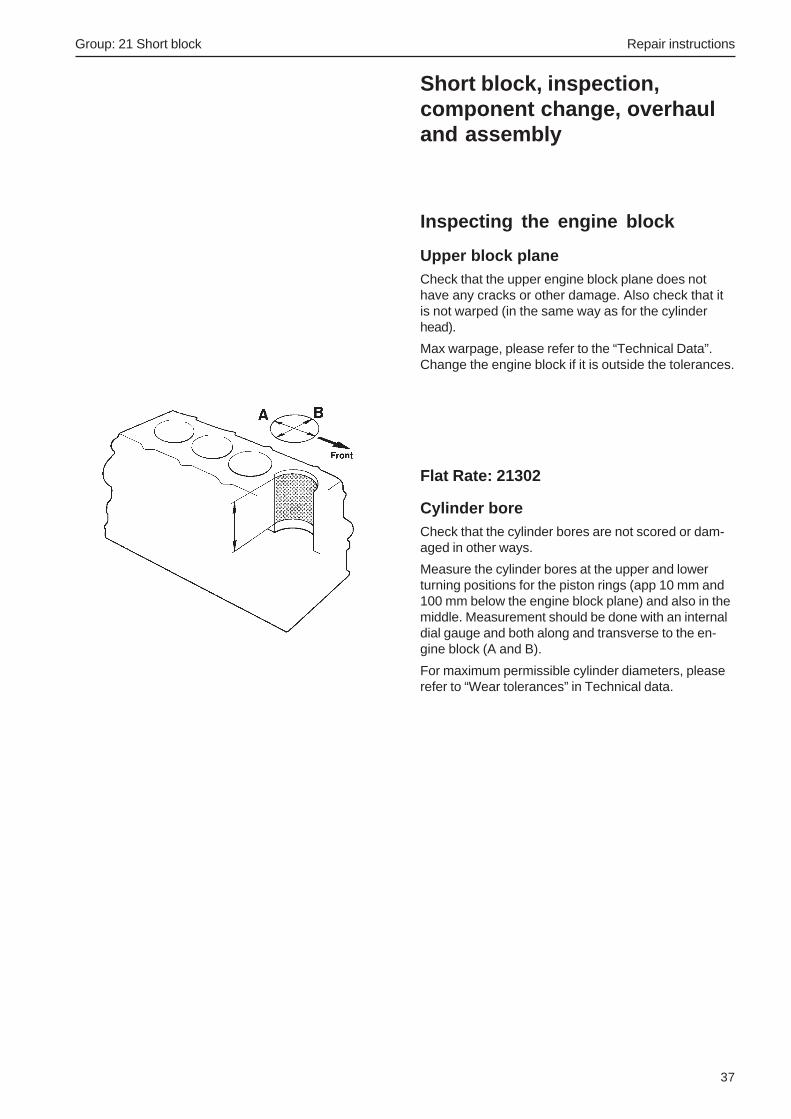
Cylinder boreCheck that the cylinder bores are not scored or dam-aged in other ways.
Measure the cylinder bores at the upper and lowerturning positions for the piston rings (app 10 mm and100 mm below the engine block plane) and also in themiddle. Measurement should be done with an internaldial gauge and both along and transverse to the en-gine block (A and B).
For maximum permissible cylinder diameters, pleaserefer to “Wear tolerances” in Technical data.

Repair instructions Group: 21 Short block
38
Inspecting the cylinder headCylinder head warping must not exceed the value giv-en in “Technical data”. The check should be done witha feeler gauge and a straight edge. Measurement isdone at six positions (A - F).
If warpage above the permissible level is found, thecylinder head must be changed. If leakage has beenfound, or if the cylinder head has blow lines, no spe-cial measurement is needed since such a cylinderhead will have to be attended to in any case.
Check the valve seats and check that the studs arefirmly seated.
Inspect the cylinder head for cracks. Carefully checkthe areas around the valve seats and the holes for theinjector nozzles.
A
F B E
AC D
Changing the valve seatsThe valve seats should be changed when distance“A”, measured with a new valve exceeds 1.8 mm.
1. Remove the old valve seat by heating it with agas torch (600 - 700oC), diagonally across theseat.
Let the cylinder heat cool for 3 - 5 min in the air.Then carefully tap the seat out with a mandrel(check that the cylinder head is not damaged).
The valve seat can also be milled out (check thatthe cylinder head is not damaged).
2. Carefully clean the valve seat bed in the cylinderhead. Check the cylinder head for cracks.
3. Cool the new valve seat with carbon dioxide snowetc. to minus 60-70oC and possibly heat the cylin-der head to 60-100oC.
4. Seat the seat into the cylinder head. Use a hy-draulic press and a suitable mandrel.
5. Machine the seats to the correct angle and width.
Group: 21 Short block Repair instructions
39
Flat Rate: 21401
Grinding of valve and valve seats
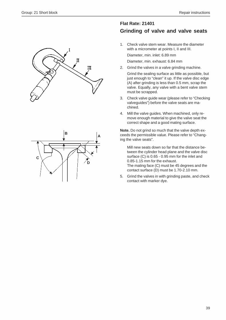
1. Check valve stem wear. Measure the diameterwith a micrometer at points I, II and III.
Diameter, min. inlet: 6.89 mm
Diameter, min. exhaust: 6.84 mm
2. Grind the valves in a valve grinding machine.
Grind the sealing surface as little as possible, butjust enough to “clean” it up. If the valve disc edge(A) after grinding is less than 0.5 mm, scrap thevalve. Equally, any valve with a bent valve stemmust be scrapped.
3. Check valve guide wear (please refer to “Checkingvalveguides”) before the valve seats are ma-chined.
4. Mill the valve guides. When machined, only re-move enough material to give the valve seat thecorrect shape and a good mating surface.
Note. Do not grind so much that the valve depth ex-ceeds the permissible value. Please refer to “Chang-ing the valve seats”.
Mill new seats down so far that the distance be-tween the cylinder head plane and the valve discsurface (C) is 0.65 - 0.95 mm for the inlet and0.85-1.15 mm for the exhaust.The mating face (C) must be 45 degrees and thecontact surface (D) must be 1.70-2.10 mm.
5. Grind the valves in with grinding paste, and checkcontact with marker dye.
BA
DC

Repair instructions Group: 21 Short block
40
Checking the valve guides*Special tools: 999 9683, 999 9696
1 Put the cylinder head on the bench, and putvalves in the valve guides.
2 Measure the wear with a dial gauge 999 9683 andmagnetic stand 999 9696.
Lift each valve about 2 mm from its seat, put themeasurement tip on the edge of the valve heatand check the wear.
Permissible clearance between valve and valveguide:
Inlet valve, max clearance 0.20 mm.
Exhaust valve, max clearance 0.25 mm.
* Note. Since the valve guides are machined directly in the cylin-der head, the cylinder head must be changed when the clear-ance is too great, even when the valve is new.

Group: 21 Short block Repair instructions
41
Flat Rate: 21407
Renovating the rocker armmechanism1. Remove the plug at the front of the rocker arm
shaft. If the shaft has a stop screw, it must be re-moved before the shaft is pulled out.
2. Disassemble the rocker arm mechanism. Removethe rockerarms, springs and washers.
3. Clean the components. Be specially careful withthe rocker arm oil ducts and the oil holes in therocker arms.
4. Check the wear of the rocker arm shaft with a mi-crometer.
5. Check whether the rocker arm bearing surfaceshave been worn oval. Check the clearance be-tween rocker arm and shaft.
Check that the spherical section of the adjust-ment screw is not deformed or worn. The threadson the pin and lock nut should be undamaged.The lock nut should be in good condition.
6. Oil the rocker arm shaft and disassemble the oth-er components.
Repair instructions Group: 21 Short block
42
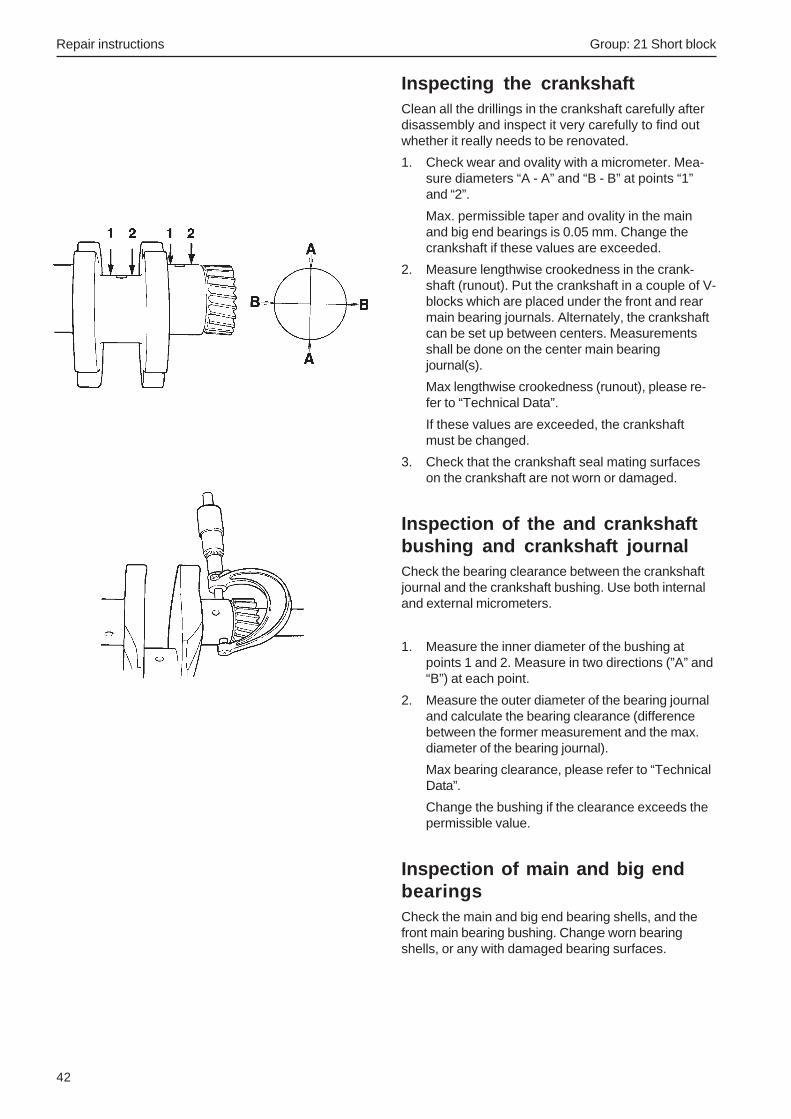
Inspecting the crankshaftClean all the drillings in the crankshaft carefully afterdisassembly and inspect it very carefully to find outwhether it really needs to be renovated.
1. Check wear and ovality with a micrometer. Mea-sure diameters “A - A” and “B - B” at points “1”and “2”.
Max. permissible taper and ovality in the mainand big end bearings is 0.05 mm. Change thecrankshaft if these values are exceeded.
2. Measure lengthwise crookedness in the crank-shaft (runout). Put the crankshaft in a couple of V-blocks which are placed under the front and rearmain bearing journals. Alternately, the crankshaftcan be set up between centers. Measurementsshall be done on the center main bearingjournal(s).
Max lengthwise crookedness (runout), please re-fer to “Technical Data”.
If these values are exceeded, the crankshaftmust be changed.
3. Check that the crankshaft seal mating surfaceson the crankshaft are not worn or damaged.
Inspection of the and crankshaftbushing and crankshaft journalCheck the bearing clearance between the crankshaftjournal and the crankshaft bushing. Use both internaland external micrometers.
1. Measure the inner diameter of the bushing atpoints 1 and 2. Measure in two directions (”A” and“B”) at each point.
2. Measure the outer diameter of the bearing journaland calculate the bearing clearance (differencebetween the former measurement and the max.diameter of the bearing journal).
Max bearing clearance, please refer to “TechnicalData”.
Change the bushing if the clearance exceeds thepermissible value.
Inspection of main and big endbearingsCheck the main and big end bearing shells, and thefront main bearing bushing. Change worn bearingshells, or any with damaged bearing surfaces.

Group: 21 Short block Repair instructions
43
Checking the big end bearingclearance:Special tools: 856927 (measurement putty)
The radial clearance of the big end bearings can bechecked by means of measurement putty part no.856927 as follows:
1. Wipe off any oil from the big end bearing and bigend journal. Apply a piece of measurement putty,the same length as the width of the bearing jour-nal, and put the putty along the big end bearingjournal. Avoid the oil hole.
2. Install the con rod and bearing cap (note thealignment marking) and tighten the con rodscrews.
Tightening torque, please refer to the “TechnicalData” chapter.
NOTE! Do not rotate the con rod or crankshaft duringmeasurement, since this spoils the measurementstrip.
3. Remove the big end cap and measure the width ofthe pressed-out measurement putty at the widestpoint. Use the rule which is enclosed with themeasurement putty.
Max permissible big end bearing clearance,please refer to the “Technical Data”.
Change the main bearing if the bearing clearanceexceeds the permissible value.

Repair instructions Group: 21 Short block
44
Piston ring inspection and fits1. Remove the piston rings with piston ring pliers.
2. Remove the gudgeon pin circlips and remove thegudgeon pin carefully, with a suitable mandrel.
3. Check that the rings do not bind in the piston ringgrooves.
4. Check the piston ring gap. Slide the ring down be-low the bottom dead center position using apiston. Change the piston ring if the gap exceeds1.0 mm.
Check the piston ring gap with new rings. Pleaserefer to the “Technical Data, specifications” chap-ter for measurements.
In general, piston rings should be changed if thereis any noticeable wear or out - of - roundness inthe cylinders, since the piston rings frequently donot end up in the same positions as they had be-fore disassembly.
Oil consumption is also of decisive importance forthe point in time when a piston ring change shouldbe done.
5. Check the clearance in the piston ring grooves.Roll the ring in its groove in the piston, and mea-sure the clearance at several points with a feelergauge. Please refer to the “Technical Data, speci-fications” chapter for measurements.
Inspection and measurement ofpiston and cylinder boreCheck the pistons for cracks and worn piston ringgrooves. Change the piston if it has deep grooves inthe skirt surface. Likewise, if the piston has one ormore cracks in the gudgeon pin hole. If any suchdamage is found, the injection equipment should alsobe checked.
Measure the piston diameter with a micrometer, atright angles to the gudgeon pin hole and 10 mm fromthe lower edge of the piston. Then measure thecylinder bore and calculate the clearance between cyl-inder and piston.
Change the piston if the clearance exceeds the maxi-mum permissible value, or if the piston diameter isless than the minimum permissible value.

Group: 21 Short block Repair instructions
45
Inspecting the con rod1. Check the con rods for cracking, straightness and
twist before considering changing the gudgeon pinbush.
Discard the connecting rod if it is cracked, bent ortwisted.
Check the wear in the “small end” with a gudgeonpin. When the clearance is correct, an oiled gud-geon pin should slowly slide through the bush un-der its own weight.
2. Use a new gudgeon pin and measure the straight-ness of the con rod, using a fixture. Max. devia-tion: 0.15 mm on 100 mm measured length
3. Measure con rod twist. Max. deviation: 0.20 mmon 100 mm measured length
Flat Rate: 21641
Changing the gudgeon pinbushing1. Press the old bush out.
2. Press the new bush in.
NOTE! Make sure that the oil hole in the bush lines upwith the drilling in the con rod. Draw a line across thehole in the con rod and the bush, with a felt tip pen.Check that the oil duct is open after pressing.
3. Broach the bush and measure the con rod with aninternal dial gauge.
4. Check the end float between the con rod andcrankshaft. Change the con rod if the end float ex-ceeds 0.035 - 0.085 mm.
Also check the gudgeon pin bushes. Please referto “Technical Data”, for the clearance betweengudgeon pin (A) and gudgeon pin bush (B).

Repair instructions Group: 21 Short block
46
Assembling the piston, pistonrings and con rod1. Install one of the circlips in the piston.
2. Oil the gudgeon pin and gudgeon ring bush.
3. Warm the piston to about 100oC. Place the pistonand con rod so that the markings line up.
The marking on the con rod and the “SHIBAURA”marking inside the piston must face the sameway.
Slide the gudgeon pin in.
NOTE! It should be possible to slide the gudgeon pinin easily. It must not be driven in.
4. Install the other circlip.
5. Check that the con rod does not move stiffly inthe gudgeon pin bush.
6. Check the big end bearing clearances. Please re-fer to “Inspecting the crankshaft” and “Inspectingthe main and big end bearings”.
7. Check the piston ring gap in the cylinder bores,and check that the rings do not bind in the pistonring grooves.
8. Install the piston rings on the pistons, using pis-ton ring pliers. Letters or markings on ring surfac-es must always be turned so that the marking fac-es upwards.
Install the oil scraper ring first. Put the expansionspring (1) for the oil scraper ring in the lower pis-ton ring groove, with the location dowel (A) insideboth ends of the spring. Check that the ends ofthe expansion spring do not overlap. Install the oilscraper ring (2) above the expansion spring.Check that the ring gap is installed with 180o dis-placement to the guide pin.
Install the ring with the tapered surface (3) in thecentre piston ring pair so that the marking facesthe piston crown.
Install the upper ring (4) with the marking up-wards.
Check that the ring openings are at 90o to eachother.
1
2
34
A

Group: 21 Short block Repair instructions
47
1
Camshafts and valve lifters,inspectionCheck with a steel rule (1), that the valve lifter matingsurfaces against the camshaft are convex or flat. Ifthe surface is concave, change the valve lifter.
If the valve lifter is worn all across the lifting surface,the valve lifter should be scrapped. The “ditch” showsthat the valve lifter has not rotated.
A dark line on the outside of the valve lifter showsthat the surface is not worn, on the other hand. It isthe condition of the valve lifters which determineswhether it is necessary to check the camshaft wear.
Check that the lifting surfaces on the camshaft andthe valve lifters do not have large areas of pittingdamage. Pitting damage can occur for various rea-sons. The damage is caused when small pieces ofmetal loosen from the hardened surface. Lifters andcamshafts with minor pitting damage can be used.Pitting damage seldom become worse.
Check that the camshaft bearing surfaces and camcurves are not abnormally worn. The cams could beobliquely worn in an axial direction, for example.
Change the camshaft if major damage or wear occurs.
NOTE! When the camshaft is changed, all the valvelifters must be changed.
Measuring the camshaftCam height (inlet and exhaust), “A” 26.5 mm
Cam height “B” (for injection pump) 41.8 mm
Cam height “C” (for injection pump) 27.0 mm
Change the camshaft if the wear limits have been ex-ceeded.

Repair instructions Group: 21 Short block
48
Acceptable wear.
The camshaft does not need to be changed.
Not acceptable wear.
NOTE! The camshaft and associated rocker armsmust be changed.
Guidelines for replacementIn normal conditions, un-evenness may occur on thecamshaft lobes in the engine. This does not meanthat the camshaft has to be changed. These marks donot have any negative influence on either engine per-formance or durability of the engine and its compo-nents.
Examples are shown below, of acceptable and not ac-ceptable wear.

Group: 21 Short block Repair instructions
49
Installing the crankshaft1. Check the cleanliness of the crankshaft drillings
and bearing surfaces, engine block and bearingcaps. Check that the bearing shells and their bedsdo not have any burrs or upsets.
2. Put the main bearings in their places in thebearing caps. Bearing shells with an oil hole mustbe placed in the upper bearing cap. Check thatthe lubrication holes in the upper bearingshells are centered on the oil ducts.
3. Oil the bearings and the main bearing journals andinstall the bearingcaps in their places. The cham-fered edges must face forwards on all bearingcaps. Please refer to the illustration, to identifythe location of the bearing caps.
4. Torque the bearing caps, please refer to the“Technical Data” chapter for tightening torque.
5. Carefully lift the crankshaft into place in the en-gine block. Align the main bearing retainer screwholes (1) before the crankshaft is pressed intoplace.
Note. Tape the crankshaft gear before lifting thecrankshaft into place, to prevent the gear teethfrom damaging the front bearing seat.
6. Torque the main bearing caps in the engine block.Tightening torque, please refer to the “TechnicalData” chapter.
7. Check that the end float does not exceed. 0.5 mmby using a special tool, magnetic stand 999 9696and dial gauge 998 9876.

Repair instructions Group: 21 Short block
50
Installing the piston in thecylinder and the oil pan
Note. After changing the crankshaft, piston or gud-geon pin, the weight difference between the con rodcomplete with piston and piston rings must not ex-ceed 10 g between each cylinder. Also refer to “Pis-tons, installing” and “Assembly of pistons, piston ringsand con rod”.
1. Lubricate the pistons and piston rings with engineoil beside the rings, so that the oil finds its wayinto the piston ring grooves. Turn the piston ringsso that the piston ring gaps are aligned at a 90o
angle to each other.
Make sure that no piston ring gap is placed cen-trally against the gudgeon pin.
2. Put the bearing shells in their places in the conrods and caps. Oil the crankshaft journal with en-gine oil.
3. Check that the markings on the piston crown orinside the piston line up with those on the con rod.
Use a piston ring compressor (1) and install thepiston with con rod in its cylinder, starting withcylinder no. 1 (forwards).
IMPORTANT! Make sure that the con rod studsto not strike the crankshaft when driven down.
The con rod with the lowest number must be in-stalled furthest forward (in cylinder no. 1) and ac-cordingly, the con rod with the highest numbergoes closest to the flywheel.
The con rod must be aligned with the marking(number/paint dot) facing the injection pump (cam-shaft side).
4. Install the bearing caps (2) and tighten the con rodscrews. Tightening torque, please refer to the“Technical Data” chapter. Bearing caps must beinstalled so that the number markings/paint markson con rod and cap coincide.Undamaged con rod screws do not need to bechanged, they can be put back again.
5. Install the oil suction pipe (3) and oil strainer (4).Tightening torque, please refer to the “TechnicalData” chapter. Use a new O - ring.
IMPORTANT! Do not press the oil suction pipedown to the bottom of the hole. There is a riskthat an oil duct could be blocked.
6. Install the sump together with a new gasket.Tightening torque, please refer to the “TechnicalData” chapter.
4 3 2

Group: 21 Short block Repair instructions
51
Installing the timing gear andinjection pumpAlso refer to “Timing gear, installation”.
1. Install the timing gear plate (1) with new gasket.
2. Oil the camshaft bearing surfaces and carefullylift the camshaft (2) into place, complete withdrive gear and regulator weights.
Note. Be careful to avoid damaging the bearings,bearing tracks and camshaft lobes.
3. Install lock plate (3) for the camshaft in the cor-rect position and torque it.
4. Put the key in place in the crankshaft and installthe crankshaft pulley (4).
IMPORTANT! The components must be oiled be-fore installation.
IMPORTANT! Make sure that the gear wheelmarkings coincide.
5. Install the thrust washer (5) on the idler wheelshaft stub. Install the idler wheel (6) in accor-dance with the markings.
NOTE! Do not turn the crankshaft before the timinggear cover has been installed.
6. Install the inner rotor (7) and the oil pump cover(8). Install shims (9), spring (10), spring washer(11) and lock washer (12).
7. Adjust the oil pump end float (13) to 0.10 - 0.15mm. Shims (9) are available in thicknesses of0.10; 0.15; 0.20 and 0.50 mm.
8. Install a new, possibly adjusted gasket for thetiming gear cover. Center the cover in front of theoil pump.
Note. Check that the tubular pin (14) in the timing cov-er can engage in the hole (15) in the oil pump cover.Turn the cover back and forwards, and center it in themid position. The stop arm (16) must be turned andheld in place when the timing cover is installed.
9. Check that the starter spring (17) is correctly lo-cated in the timing cover, and is connected to theregulator arm (18).
Put the timing gear cover in place. Insert theregulator arm through the hole in the engine block.Screw the timing gear cover down.
7. Turn the stop arm (19) clockwise and connect thearm (20) to the injection pump. Install the clip(21).
7
56
8
1210
11
9
13
9
2
3
1
4
1714 1815 16

Repair instructions Group: 21 Short block
52
NOTE! Be careful to ensure that the shim/gasketwhich was placed underneath the injection pumpflange is put back, before the pump is placed in theblock (applies when the pump has been removed).
8. Torque the injection pump, please refer to the“Technical Data” chapter for tightening torque.
9. Install a new front crankshaft seal, please refer to“Front crankshaft seal, changing”. Put the key inplace in the crankshaft and install the crankshaftpulley. Tightening torque, please refer to the“Technical Data” chapter.
19 21 20
Flank clearance, checking
Use a feeler gauge to measure the flank clearance (1)between the oil pump gear and the camshaft gear.
Use a feeler gauge to measure the flank clearance (2)between the oil pump gear and the crankshaft gear.
Please refer to the “Technical Data” chapter for minand max values.

Group: 21 Short block Repair instructions
53
Measuring the piston height,installing the cylinder head andother assemblyAlso refer to “Cylinder head, installation”.
1. Clean the cylinder head and engine block matingplanes. Remove any rust from screw holes andfrom the threads on the cylinder head screws.
2. Put the valve lifters in their original places.
IMPORTANT! Please refer to “Timing gear, as-sembly”, for the positions of the valve lifters.
3. Put the new cylinder head gasket in place withthe marking (1) upwards. Check that the tubularpins (2) are installed in the block.
NOTE! The new gasket must be of the same thick-ness as the old one.
NOTE! If a piston, con rod, crankshaft or engine blockhas been changed, new measurement must be done.
4. Dip the cylinder head screws in engine oil andleave them to run off on a strainer. The screwsshould have stopped dripping when they are in-stalled (otherwise oil cold well up and be regardedas leakage).
IMPORTANT! The screws are phosphated andmust not be cleaned with a steel wire brush. Ifthe cylinder head is painted, the contact surfac-es for the cylinder head screws must be freefrom paint. The clamping force in the joint couldotherwise be very poor.
5. Put the cylinder head in place.
6. Torque the cylinder head screws (3) in three stag-es, where the last stage is to the stated torque.Tightening schedule and torque, please refer to“Technical Data”.
Re-tighten all screws.
7. Install the glowplugs (4) and busbar (5).
Difference in heightbetween pistons andengine block plane
0.55 to 0.64 mm
0.65 to 0.75 mm
Gasket thickness
1.2 mm
1.3 mm
1
2
3 4 5
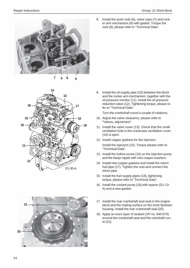
Repair instructions Group: 21 Short block
54
8. Install the push rods (6), valve caps (7) and rock-er arm mechanism (8) with gasket. Torque thenuts (9), please refer to “Technical Data”.
67 89
9. Install the oil supply pipe (10) between the blockand the rocker arm mechanism, together with theoil pressure monitor (11). Install the oil pressurereduction valve (12). Tightening torque, please re-fer to “Technical Data”.
Turn the crankshaft round a couple of rotations.
10. Adjust the valve clearance, please refer to“Valves, adjustment”.
11. Install the valve cover (13). Check that the smallventilation hole in the crankcase ventilation cover(14) is open.
12. Install copper gaskets for the injectors.
Install the injectors (15). Torque please refer to“Technical Data”.
13. Install the hollow screw (16) on the injection pumpand the banjo nipple with new copper washers.
14. Install new copper gaskets and install the returnfuel pipe (17). Tighten the nuts and connect thereturn pipe.
15. Install the fuel supply pipes (18), tighteningtorque, please refer to “Technical Data”.
16. Install the coolant pump (19) with spacer (D1-13-A) and a new gasket.
14
17
16
15
13
12
11
18
19
10
17. Install the rear crankshaft seal seat in the engineblock and the mating surface on the inner flywheelhousing. Install the rear crankshaft seal (20).
18. Apply an even layer of sealant (VP no. 840 879)around the crankshaft seal and the camshaft cov-er (21).
21
20
D1-30-A

Group: 21 Short block Repair instructions
55
19. Install the inner flywheel housing (22). Install theflywheel (23) as previously marked, please referto “Technical Data” for tightening torque. Then in-stall the flexible coupling (24) and the flywheelhousing (25). Install the engine speed sensor (26)on the flywheel housing.
20. Install the dipstick (27).
20. Install the fuel filter bracket (28) with anchorageand feed pump (29). Please refer to “TechnicalData” for tightening torque.
Connect the fuel hoses and tighten the hoseclamps.
30
31
323334
35
37
36
D1-13-A
21. Install the heat exchanger/exhaust manifold (30)and sea water pump (31).
22. Install the starter motor (32) and alternator (33),together with the front engine mounting (34).
23. Install the expansion tank with fixing yoke (35).
24. Connect all coolant hoses (36). Tighten all hoseclamps and brackets.
25. Install the electronic box (37) with cable harness,connect the connectors and other electrical con-nections. Clamp the cable harness as previouslynoted.
26. Install the induction silencer (38).
27. Remove the engine fixture and install the enginemounting (39).
28. Install a new oil filter (40). Add oil and coolant, asspecified in “Technical Data”.
29. Install the engine in the boat. Connect the remain-ing connections and controls to the engine. Openthe fuel taps and the sea cock. Start the engineand check carefully that no leakage occurs.
22
27
23
24
26
25
2829
40
38
D1-30-A39

Repair instructions Group: 21 Short block
56
Cylinder head, removal
Coolant drained. Air filter housing, heat exchangerand coolant pump with spacer (D1-13) removed.
1
Remove the screw (1) which holds the fuel filter brack-et to the cylinder head.
Unscrew the valve cover.
Undo the cable (2) for the glow plugs.
2
Undo and remove the injector pipes (1). Undo and re-move the return fuel pipe (2).
IMPORTANT! Seal all openings in the fuel sys-tem with protective caps.
3
Undo the oil supply pipe (1) by the cylinder head.
Unscrew the injectors (2).
IMPORTANT! Seal all openings on the injectorswith protective caps.
Unscrew the nuts (3) which hold the rocker armbridge. The D1-20, D1-30 and D2-40 engines alsohave screws which must be undone. Carefully prisethe rocker arm bridge loose.
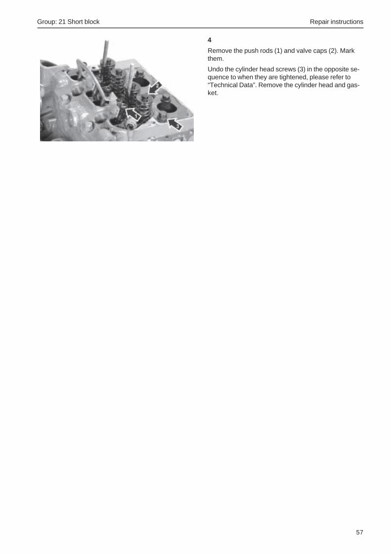
Group: 21 Short block Repair instructions
57
4
Remove the push rods (1) and valve caps (2). Markthem.
Undo the cylinder head screws (3) in the opposite se-quence to when they are tightened, please refer to“Technical Data”. Remove the cylinder head and gas-ket.

Repair instructions Group: 21 Short block
58
Valves, removing
Cylinder head removed.
Special tools: 885023, 885498
1
Remove the busbar (1) and glow plugs (2).
Remove the valves (3) with a valve compressor, toolnos. 885023 and 885498. Mark the valves.
Remove the valve seals.
Valves, installationSpecial tools: 885023, 885498
1
Install the valve (1) in the cylinder head as marked.Install a new valve seal (2), spring (3) and valvespring washer (4).
Put the valve compressor in place. Compress thevalve spring and install the collets (5).
2
Install the glow plugs and tighten to the specifiedtorque, please refer to the “Technical Data” chapter.Install the bus bar.

Group: 21 Short block Repair instructions
59
Cylinder head, installationSpecial tools: 998 9876, 999 5192
1
Check the piston height with tools 9989876 and9995192. Select a new cylinder head gasket, pleaserefer to “Technical data”.
Check that the valve lifters are in place.
2
Check that the engine block guide pins for the cylinderhead are in place. Install a new cylinder head gasketwith the marking upwards.
Put the cylinder head in place. Insert the screws (1)and torque them as in the tightening schedule, to thetorque specified in “Technical Data”.
3
Install the push rods (1) and valve caps (2).

Repair instructions Group: 21 Short block
60
4
Install a new seal on the rocker arm bridge (1). Installa new rocker arm bridge. Make sure that the pushrods and rocker arms (2) are correctly aligned.
Tighten the nuts (3) evenly to the specified torque,please refer to the “Technical Data” chapter.
5
Install the oil supply pipe (1) on the cylinder head withnew seals.
6
Installing the injectors:
Apply sealant part. no. 840879 to the threads of thetwo lowest screws (1).
Put new copper seals on the bottom of the cylinderhead.
Install the injectors and tighten them evenly to thespecified torque, please refer to the “Technical Data”chapter.
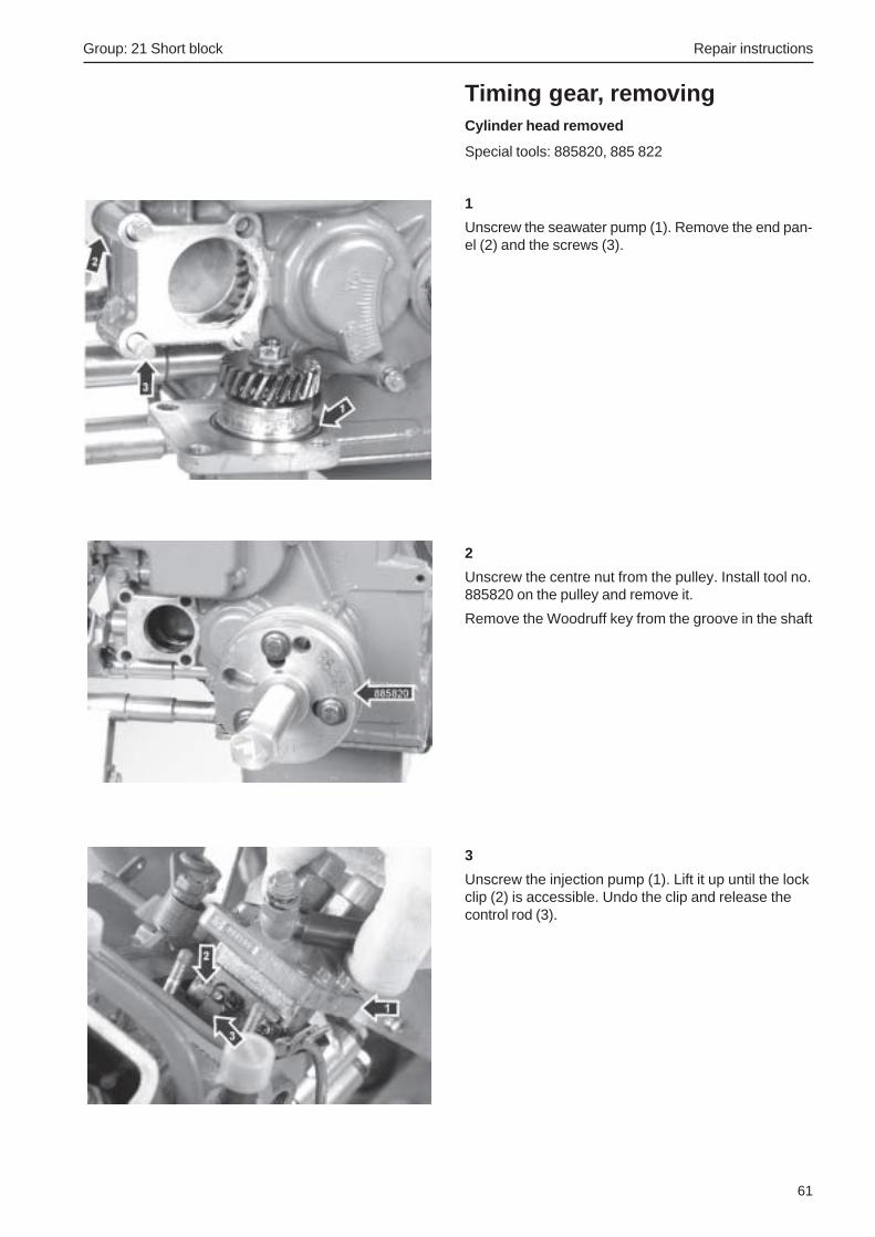
Group: 21 Short block Repair instructions
61
Timing gear, removingCylinder head removed
Special tools: 885820, 885 822
1
Unscrew the seawater pump (1). Remove the end pan-el (2) and the screws (3).
2
Unscrew the centre nut from the pulley. Install tool no.885820 on the pulley and remove it.
Remove the Woodruff key from the groove in the shaft
3
Unscrew the injection pump (1). Lift it up until the lockclip (2) is accessible. Undo the clip and release thecontrol rod (3).

Repair instructions Group: 21 Short block
62
4
Unscrew the timing gear cover screws (1) and nut (2).Remove the cover.
5
Undo the fuel pipe from the fuel filter (1).
Unscrew the fuel feed pump (2). Wipe up the fuel thathas run out.
6
Remove the valve lifters with magnetic tool 885822.
IMPORTANT! Mark the valve lifters so that theyare put back in the same positions. The D1-20and D2-40 engines have some valve lifterswhich are chamfered off.

Group: 21 Short block Repair instructions
63
7
Rotate the camshaft until the socket cap screw (1) be-comes visible in the hole in the camshaft drive gear.Unscrew the socket cap screw and hex head screw(2). Remove the lock plate (3).
Remove the camshaft regulator sleeve (4).
Pull the camshaft out carefully.
IMPORTANT! There is a risk that the inner cam-shaft bearing can be damaged by a camshaftlobe if it is pulled out with force.
8
Remove the circlip (1) on the oil pump shaft. Removeall components of the oil pump. Note the spacerwasher (2) inside the oil pump gear.
9
Unscrew the remaining screws (1). Remove the timinggear plate (2).
Undo the crankshaft gear (3) with a puller. Removethe gear wheel and its Woodruff key.
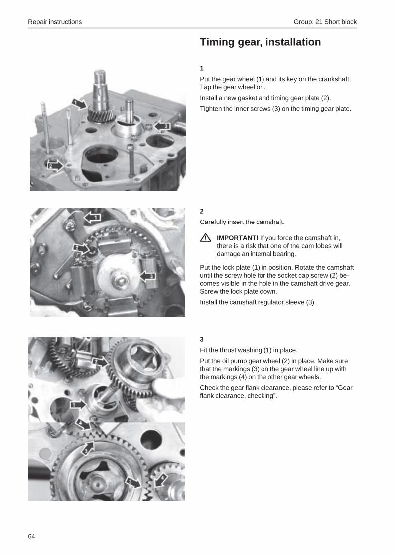
Repair instructions Group: 21 Short block
64
Timing gear, installation
1
Put the gear wheel (1) and its key on the crankshaft.Tap the gear wheel on.
Install a new gasket and timing gear plate (2).
Tighten the inner screws (3) on the timing gear plate.
2
Carefully insert the camshaft.
IMPORTANT! If you force the camshaft in,there is a risk that one of the cam lobes willdamage an internal bearing.
Put the lock plate (1) in position. Rotate the camshaftuntil the screw hole for the socket cap screw (2) be-comes visible in the hole in the camshaft drive gear.Screw the lock plate down.
Install the camshaft regulator sleeve (3).
3
Fit the thrust washing (1) in place.
Put the oil pump gear wheel (2) in place. Make surethat the markings (3) on the gear wheel line up withthe markings (4) on the other gear wheels.
Check the gear flank clearance, please refer to “Gearflank clearance, checking”.

Group: 21 Short block Repair instructions
65
4
Install the pump gear (1), end washer (2), shims (3),spring (4) and bush (5) in the oil pump gear. Put thecirclip (6) on the shaft.
NOTE! Note that the end washer (2) has a hole (7)which must mate up with the guide pin in the timinggear cover.
Install a new gasket on the timing cover.
NOTE! If the gasket has a center section (8), thismust be cut away.
5
Put the control rod (1) on the heel (2) in the timinggear cover. Turn the stop arm (3) round so that thecontrol rod is held against the heel.
6
Install the timing gear cover at the same time as thecontrol rod (1) is held fixed by the stop arm (2).
Put the timing gear cover in place. Make sure that thecontrol rod ends up in the correct position and that thepin (3) engages in the hole (4) in the oil pump endwasher.
Screw the timing gear cover down.

Repair instructions Group: 21 Short block
66
7
Put a new O-ring (1) in the groove in the seawaterpump.
Install the rear end piece (2) with a new gasket and itsfour screws (3).
NOTE! The longest screws must be put on the out-side (D1-13, D1-20).
Install the seawater pump and screw it in place.
8
Install the pulley key on the crankshaft.
Install the pulley and tighten it to the specified torquewith the center nut, please refer to the “TechnicalData” chapter.
9
Put the valve lifters in place as marked.
IMPORTANT! All valve lifters must be put backin their old places. Not that on engine D1-20,valve lifter no. 2 for cylinder 1 has one chamfer(1). On engine D2-40, both valve lifters for cylin-der 1 have one chamfer.
D1-20 A

Group: 21 Short block Repair instructions
67
Pistons, removalEngine oil drained. Cylinder head removed.
1
Turn the engine upside down. Undo the oil drain pipeanchorage (1) on the cylinder head.
Unscrew the sump (2) and remove it together with theoil drain pipe (3).
2
Unscrew the oil suction strainer (1). Remove the suc-tion pipe (2) with its O-ring.
Unscrew the bearing caps (3) for the con rods.
IMPORTANT! Note the markings on the bearingcaps and their locations.
3
Press the pistons out.
NOTE! There might be a soot deposit on the top ofthe cylinder bores. Remove the deposit to make iteasier to press the pistons out.

Repair instructions Group: 21 Short block
68
Big end bearing, changePistons, removed
1
Remove the big end bearings (1) and put the newones in position.
Flat Rate: 21320
Pistons, change
1
Note the positions of the pistons in relation to thecrankshaft.
Remove the circlips (1) and press the gudgeon pin out(2).
2
Clean the gudgeon pin bushing and check it.
3
Install a new piston in the correct position.
Press the gudgeon pin in.
Install the circlips with the lugs facing upwards.

Group: 21 Short block Repair instructions
69
Pistons, installation
1
Also refer to “Assembly of pistons, piston rings andcon rod”.
Install a piston ring compressor on the piston.
Lubricate the con rod bearing shells and studs withengine oil.
2
Turn the crankshaft round so that the big end bearingis in the lowest position for the piston to be installed.
Install the piston (1) in the bore and carefully tap itdown. The piston marking “ SHIBAURA” must facethe injection pump side.
IMPORTANT! Make sure that the con rod studsto not strike the crankshaft when driven down.
3
Install the big end bearing cap as marked. Torque to23 Nm (D1-13, D1-20 or 32 Nm (D1-30, D2-40).
Check the movement of the big end bearing.
Repeat the procedure to install the remaining pistons.

Repair instructions Group: 21 Short block
70
Crankshaft, removeRemoved pistons, flywheel and timing gear
1
Unscrew the inner timing gear plate (1).
2
Remove the rear crankshaft seal (1) from the crankshaft.
3
Unscrew the oil pressure reduction valve.
4
Undo the screws (1) which hold the main bearing caps.
Lift the crankshaft out.
NOTE! Tape the crankshaft gear teeth to protect thebearing when the shaft is pulled out.
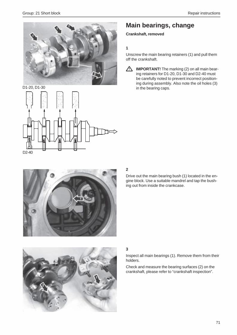
Group: 21 Short block Repair instructions
71
Main bearings, changeCrankshaft, removed
1
Unscrew the main bearing retainers (1) and pull themoff the crankshaft.
IMPORTANT! The marking (2) on all main bear-ing retainers for D1-20, D1-30 and D2-40 mustbe carefully noted to prevent incorrect position-ing during assembly. Also note the oil holes (3)in the bearing caps.
2
Drive out the main bearing bush (1) located in the en-gine block. Use a suitable mandrel and tap the bush-ing out from inside the crankcase.
3
Inspect all main bearings (1). Remove them from theirholders.
Check and measure the bearing surfaces (2) on thecrankshaft, please refer to “crankshaft inspection”.
D1-20, D1-30
D2-40
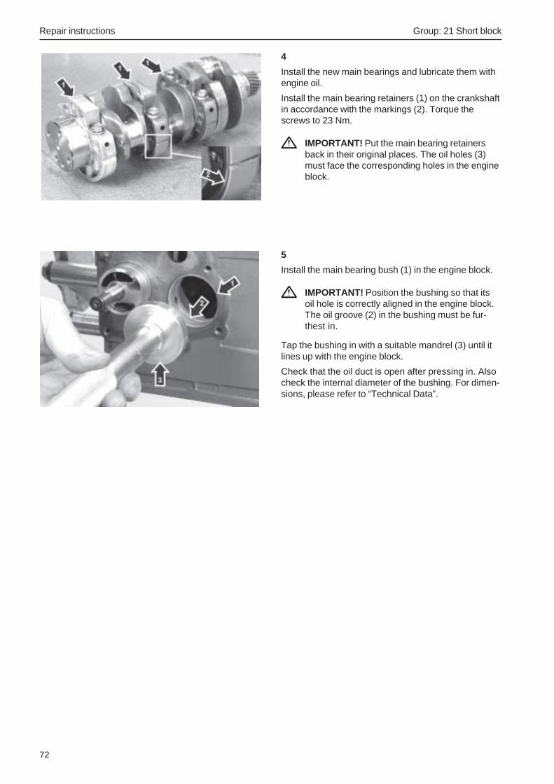
Repair instructions Group: 21 Short block
72
4
Install the new main bearings and lubricate them withengine oil.
Install the main bearing retainers (1) on the crankshaftin accordance with the markings (2). Torque thescrews to 23 Nm.
IMPORTANT! Put the main bearing retainersback in their original places. The oil holes (3)must face the corresponding holes in the engineblock.
5
Install the main bearing bush (1) in the engine block.
IMPORTANT! Position the bushing so that itsoil hole is correctly aligned in the engine block.The oil groove (2) in the bushing must be fur-thest in.
Tap the bushing in with a suitable mandrel (3) until itlines up with the engine block.
Check that the oil duct is open after pressing in. Alsocheck the internal diameter of the bushing. For dimen-sions, please refer to “Technical Data”.

Group: 21 Short block Repair instructions
73
Crankshaft, assembly
1
Lift the crankshaft into place.
Align the main bearing retainer screw holes (1) beforethe crankshaft is pressed into place.
2
Carefully tap the crankshaft into place if necessary,and torque the main bearing retainers to 27 Nm.
Check that the crankshaft can be turned easily.
3
Install the oil pressure reduction valve with a newseal. Torque to 64 Nm.
Install a rear crankshaft seal, please refer to “Rearcrankshaft seal, changing”.
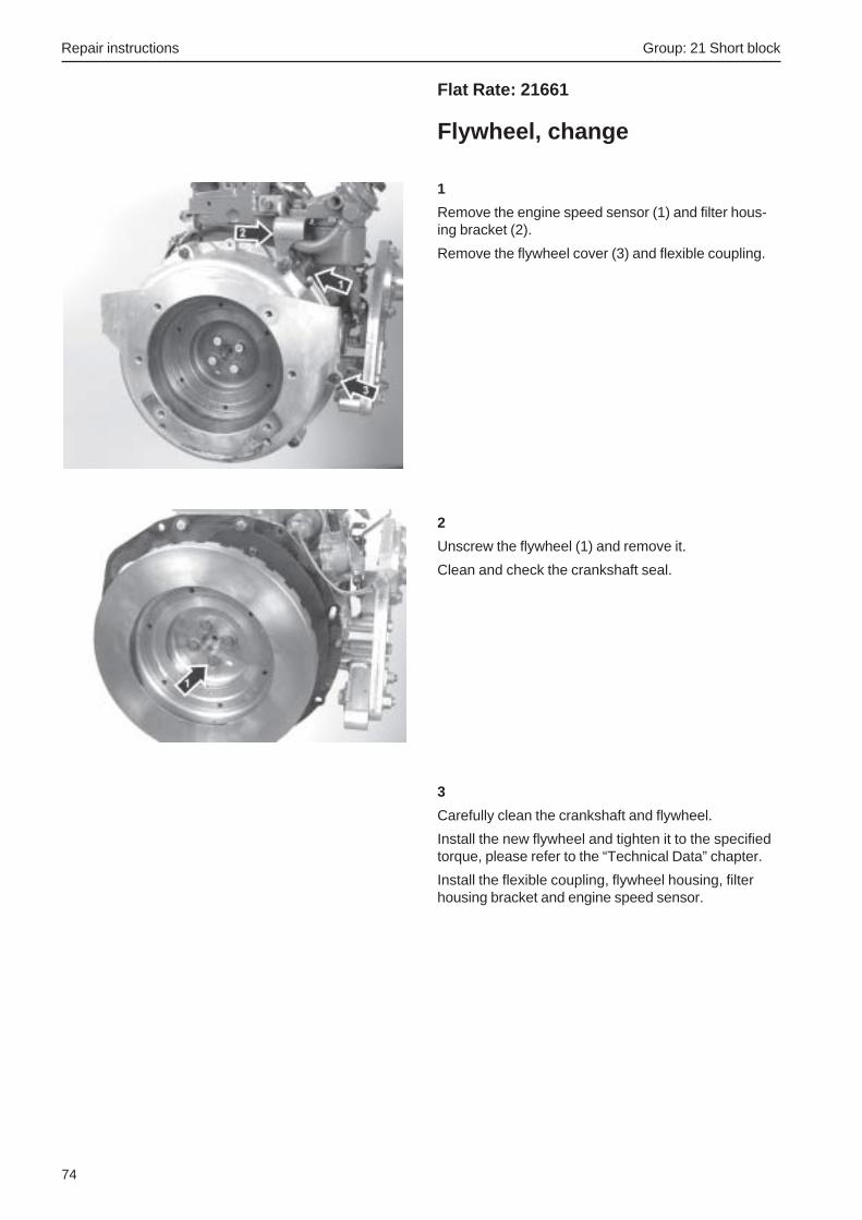
Repair instructions Group: 21 Short block
74
Flat Rate: 21661
Flywheel, change
1
Remove the engine speed sensor (1) and filter hous-ing bracket (2).
Remove the flywheel cover (3) and flexible coupling.
2
Unscrew the flywheel (1) and remove it.
Clean and check the crankshaft seal.
3
Carefully clean the crankshaft and flywheel.
Install the new flywheel and tighten it to the specifiedtorque, please refer to the “Technical Data” chapter.
Install the flexible coupling, flywheel housing, filterhousing bracket and engine speed sensor.

Group: 21 Short block Repair instructions
75
Crankcase seal rear, changeFlywheel removed
1
Unscrew the inner timing gear plate (1).
2
Remove the rear crankshaft seal (1).
Check that the area for the crankshaft seal on the en-gine block, the crankshaft and the inner flywheelhousing are cleaned.
Lubricate the lip of the seal on the new crankshaftseal with engine oil and put the seal in place.
Apply sealant part no. 840879 all round the crankshaftseal (2) and the camshaft cover (3).
Fix the inner flywheel plate.
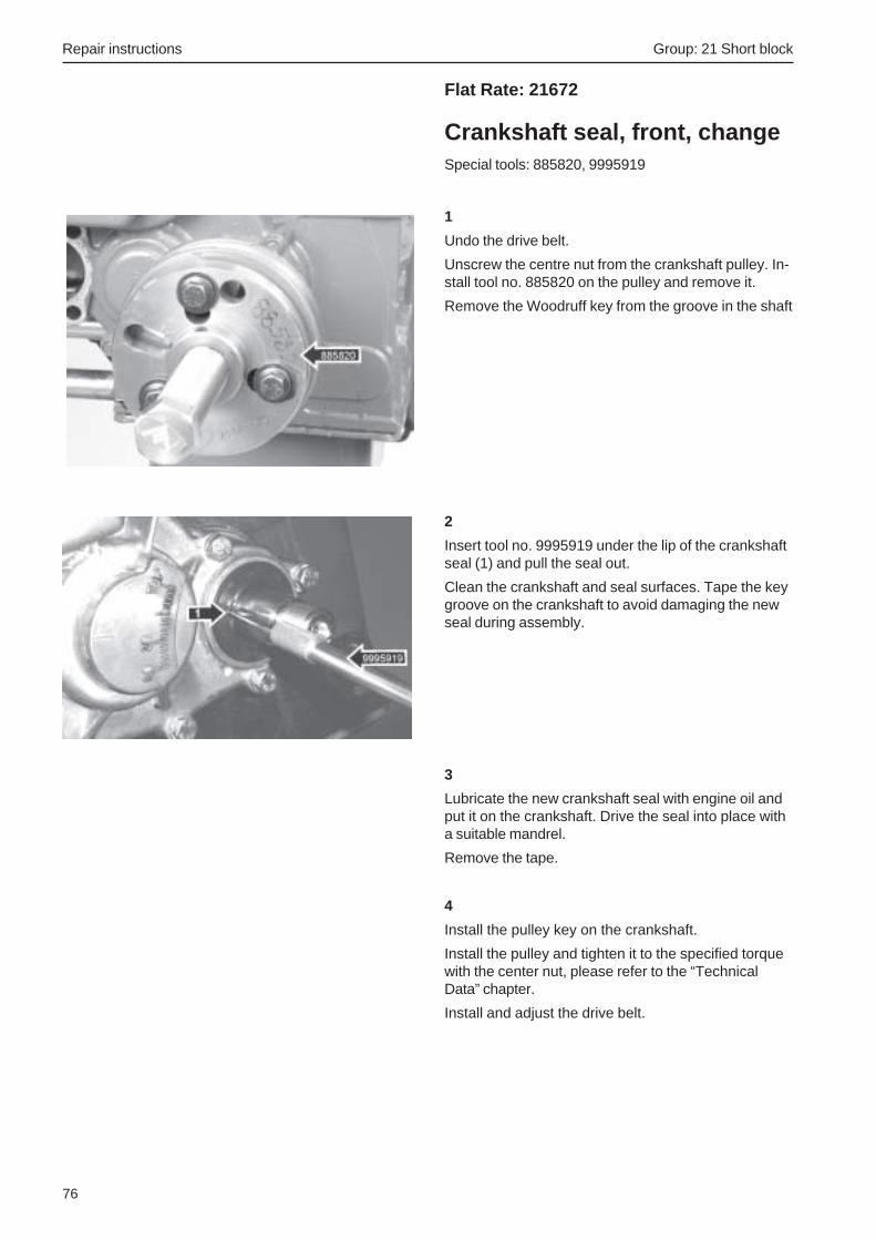
Repair instructions Group: 21 Short block
76
Flat Rate: 21672
Crankshaft seal, front, changeSpecial tools: 885820, 9995919
1
Undo the drive belt.
Unscrew the centre nut from the crankshaft pulley. In-stall tool no. 885820 on the pulley and remove it.
Remove the Woodruff key from the groove in the shaft
2
Insert tool no. 9995919 under the lip of the crankshaftseal (1) and pull the seal out.
Clean the crankshaft and seal surfaces. Tape the keygroove on the crankshaft to avoid damaging the newseal during assembly.
3
Lubricate the new crankshaft seal with engine oil andput it on the crankshaft. Drive the seal into place witha suitable mandrel.
Remove the tape.
4
Install the pulley key on the crankshaft.
Install the pulley and tighten it to the specified torquewith the center nut, please refer to the “TechnicalData” chapter.
Install and adjust the drive belt.

Group: 21 Short block Repair instructions
77
Flat Rate: 21403
Valves, adjustmentStationary, cold engine
1
Remove the air filter housing (1) and valve housing(2).
2
D1-13
Crank the engine clockwise until the valves (1) for no.1 cylinder shift position. Then crank the engine exact-ly one more turn. You can now adjust the valves forno. 1 cylinder. Please refer to item 3 for the adjust-ment procedure.
Crank the engine until the valves (2) for no. 2 cylindershift position. Then crank the engine exactly one moreturn. Adjust the valves for no. 2 cylinder.
D1-20, D1-30
Crank the engine clockwise until the valves for no. 1cylinder shift position. Adjust no. 2 inlet valve (1) andno. 3 exhaust valve (2). Please refer to item 3 for theadjustment procedure.
Crank the engine clockwise until the valves for no. 2cylinder shift position. Adjust no. 3 inlet valve (3) andno. 1 exhaust valve (4).
Crank the engine clockwise until the valves for no. 3cylinder shift position. Adjust no. 1 inlet valve (5) andno. 2 exhaust valve (6).

Repair instructions Group: 21 Short block
78
D2-40
Crank the engine clockwise until the valves for no. 4cylinder shift position. Adjust no. 1 inlet and exhaustvalve (A). Please refer to item 3 for the adjustmentprocedure.
Crank the engine clockwise until the valves for no. 2cylinder shift position. Adjust no. 3 inlet and exhaustvalve (B).
Crank the engine clockwise until the valves for no. 1cylinder shift position. Adjust no. 4 inlet and exhaustvalve (C).
Crank the engine clockwise until the valves for no. 3cylinder shift position. Adjust no. 2 inlet and exhaustvalve (D).
3
Adjustment
Undo the locknut (1) with a ring wrench. Measure thevalve clearance (2) with a feeler gauge. Adjust thevalve clearance with the adjustment screw (3).
The correct valve clearance for all valves and enginesis 0.2 mm.
When the correct valve clearance has been reached,tighten the locknut (1).
4
Install the valve cover with a new seal.
Install the air filter housing.
Test run the engine and check that no oil leakage oc-curs.
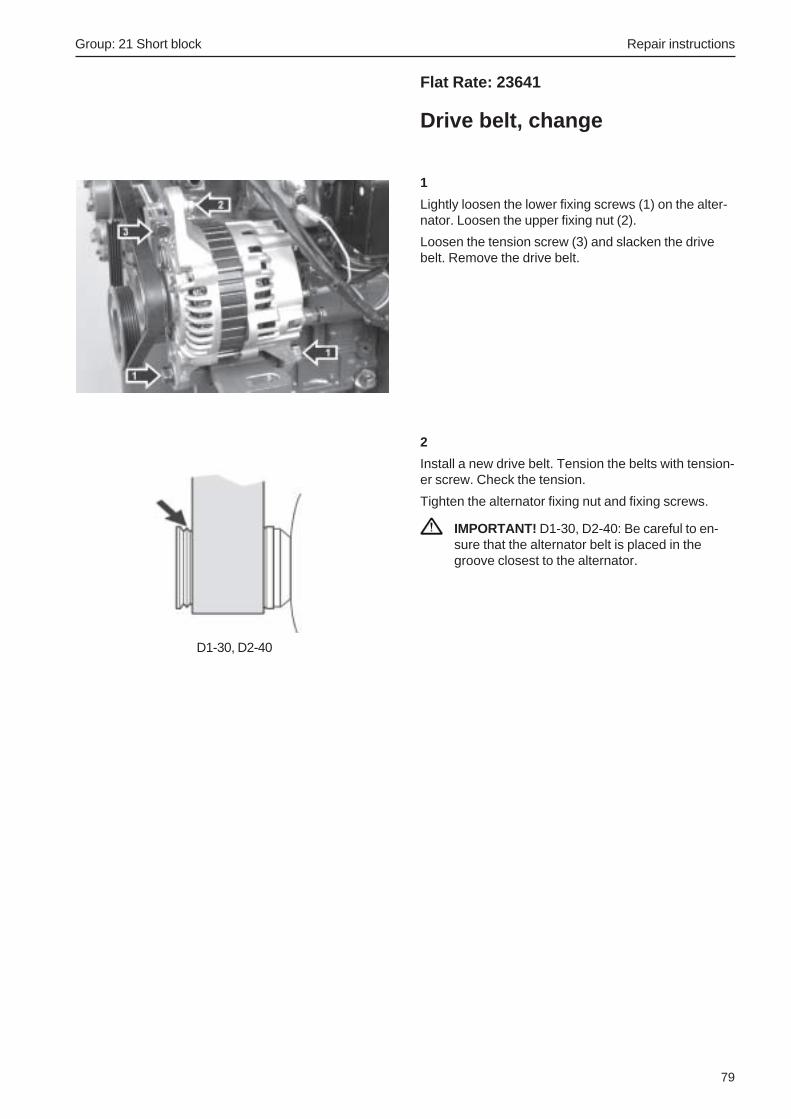
Group: 21 Short block Repair instructions
79
Flat Rate: 23641
Drive belt, change
1
Lightly loosen the lower fixing screws (1) on the alter-nator. Loosen the upper fixing nut (2).
Loosen the tension screw (3) and slacken the drivebelt. Remove the drive belt.
2
Install a new drive belt. Tension the belts with tension-er screw. Check the tension.
Tighten the alternator fixing nut and fixing screws.
IMPORTANT! D1-30, D2-40: Be careful to en-sure that the alternator belt is placed in thegroove closest to the alternator.
D1-30, D2-40

Repair instructions Group: 22 Lubrication system
80
Oil pump bearing, changingTiming gear and crankshaft removed
Special tools: 384 9639 (D1-13, D1-20), 384 9640 (D1-30, D2-40)
1
Drive out the oil pump bearing section (1) located inthe engine block. Tap it out from inside the crank-case.
2
Use special tool 384 9639 for D1-13 and D1-20, 3849640 for D1-30 and D2-40.
First screw the guide pin (1) for the tool into the en-gine block.
Then put the new oil pump bearing (2) into the toolblock (3).
NOTE! It is important that the engine block surfacetouching the tool is clean and even. The tool blockmust be oiled.
3
Place the tool block with the bearing in place, usingthe guide pin.
Tap the bearing into place until the tool bottoms onthe cylinder head.
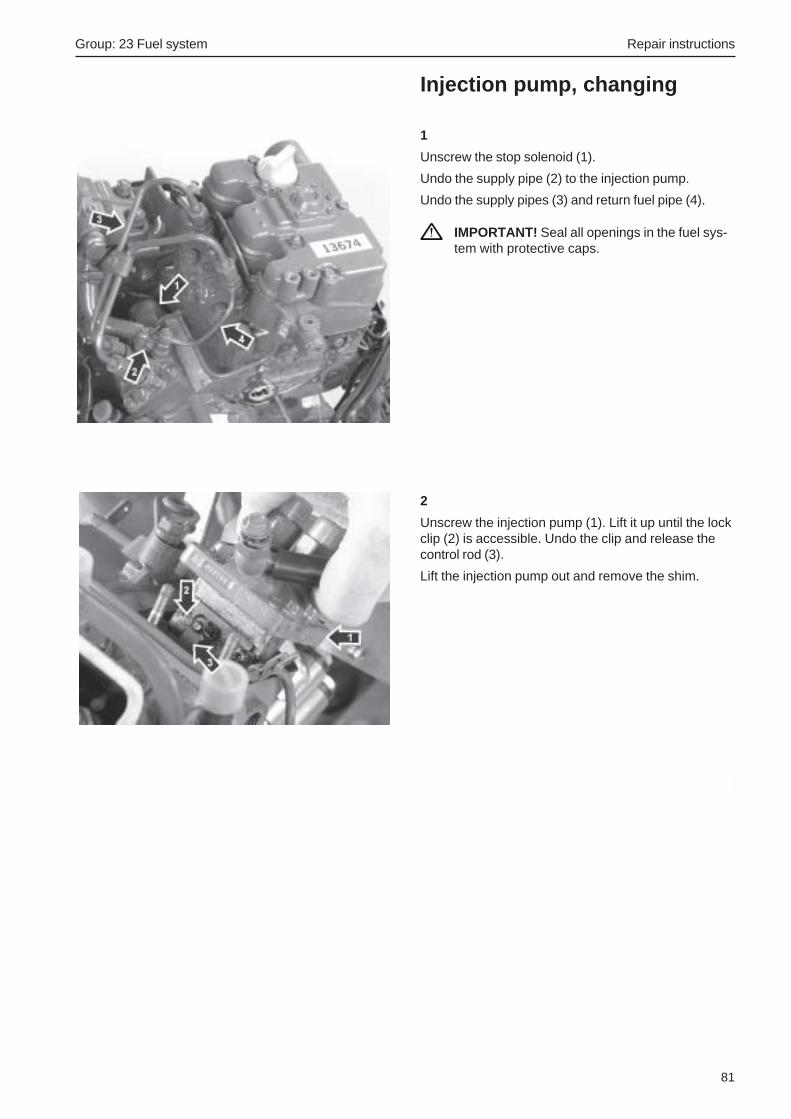
Group: 23 Fuel system Repair instructions
81
Injection pump, changing
1
Unscrew the stop solenoid (1).
Undo the supply pipe (2) to the injection pump.
Undo the supply pipes (3) and return fuel pipe (4).
IMPORTANT! Seal all openings in the fuel sys-tem with protective caps.
2
Unscrew the injection pump (1). Lift it up until the lockclip (2) is accessible. Undo the clip and release thecontrol rod (3).
Lift the injection pump out and remove the shim.
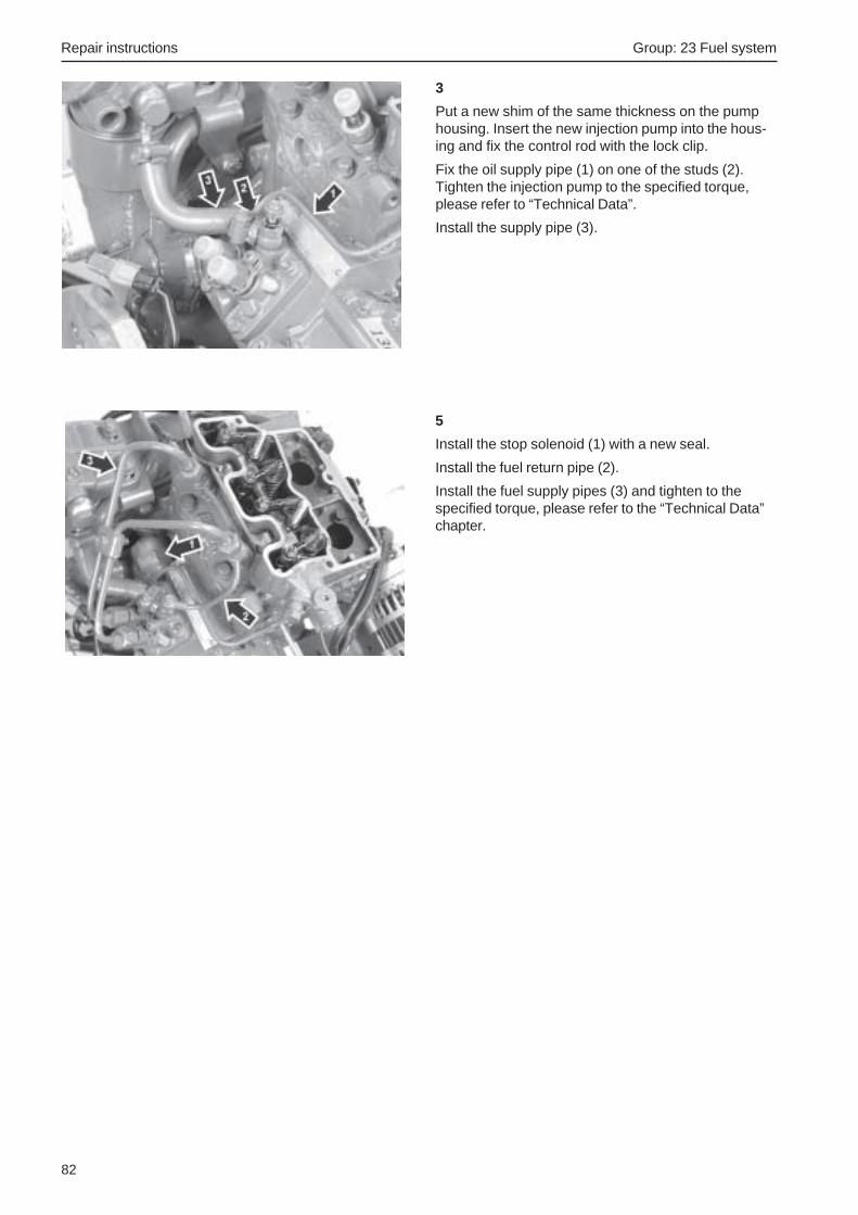
Repair instructions Group: 23 Fuel system
82
3
Put a new shim of the same thickness on the pumphousing. Insert the new injection pump into the hous-ing and fix the control rod with the lock clip.
Fix the oil supply pipe (1) on one of the studs (2).Tighten the injection pump to the specified torque,please refer to “Technical Data”.
Install the supply pipe (3).
5
Install the stop solenoid (1) with a new seal.
Install the fuel return pipe (2).
Install the fuel supply pipes (3) and tighten to thespecified torque, please refer to the “Technical Data”chapter.

Group: 23 Fuel system Repair instructions
83
Flat Rate: 23710
Injectors, changing1
Clean round the injectors (1).
Undo the fuel supply pipes (2) by the injection pumpand the injectors. Lift the fuel supply pipes away to-gether.
Remove the nut (3) at the top of each injector, use thenut (4) underneath the fuel return pipe (5) to avoidkinking the pipe. Lift the return fuel pipe away.
Unscrew the injectors. Remove the copper seals un-der the injectors.
IMPORTANT! Seal all openings in the fuel sys-tem with protective caps.
2
Install the new injectors with new copper seals. Applysealant, part no. 840 879 to the two lowest threads(1). Tightening torque, please refer to the “TechnicalData” chapter.
Install the new return fuel pipe, use the nut underneaththe fuel return pipe to avoid kinking the pipe.
Install the fuel supply pipes. Check that they do notcome out of alignment, and tighten the nuts. Tighten-ing torque, please refer to the ”Technical Data” chap-ter.
3
Start the engine and check that no leakage occurs.
1
2
3
4
5

Repair instructions Group: 23 Fuel system
84
Flat Rate: 23701
Renovating the injectors1. Clean the outside of the injector.
2. Fix the injector (holder) in a vise. Unscrew the in-jector nut and take the injector apart.
Note. Be careful that the injector nozzle does not fallout during disassembly.
3. Pull the injector nozzle out of the injector sleeveand put the components in cleaning petrol (gaso-line).
Note. Make sure that the injector needles and injectorsleeves which belong with each other, and fit together,are not mixed up if several injectors are cleaned at thesame time. To avoid mixing up, the injectors shouldbe put in an injector stand or in different compart-ments.
4. Check each injector carefully with an illuminatedmagnifier or an injector microscope. Also checkthe other components.
5. When you install a new injector, it is importantthat conservation oil is washed off the injectorneedle and sleeve before the injector is assem-bled (avoid skin contact with the sliding surfacesof the needle).
Clean the components in chemically pure petrol(gasoline). Check that the injector needle slides inthe sleeve, with no tendency to binding.
6. Dip the injector components in pure Diesel or test-ing oil, and fit the components together. Use theoriginal thickness of adjustment washer(s) to setthe opening pressure.
7. Check the opening pressure, jet pattern and seal-ing in an injector tester.
12
3 45 6
78
9
1. Injector nut 6. Adjustment washers2. Injectors 7. Injector holder3. Joining piece 8. Washer4. Compression screw 9. Nut5. Spring

Group: 23 Fuel system Repair instructions
85
Injectors, testingTesting is done in an injector tester. During the test,the opening pressure and sealing are the most impor-tant things. The spray pattern is more difficult to as-sess, and does not give a reliable indication of theinjector’s status.
WARNING! Be careful when testing injectors,avoid getting the fuel jet from an injector on un-protected parts of your body. The jet has suchpowerful penetration ability that it can force itsway in under your skin and cause blood poison-ing (septicemia).
Opening pressureWith the pressure gauge connected, press the injectortester lever down slowly until the injector opens andreleases fuel. Read off the opening pressure at theopening instant.
If the value read does not coincide with the specifiedvalue, the setting must be changed. This is done withwashers.
Note. The opening pressure is increased or reducedby about 1 MPa by a change in thickness of thespacer by 0.1 mm.
Injectors, check
Spray pattern1. Pump the injector tester, special tool 9999 772,
and check the injector spray pattern. The fuel jetshould be conical and in line with the centerline ofthe injector. Fuel drops must not occur in the jet.
2. Check that the fuel jet has a circular cross sec-tion.
SealingWhen sealing is checked, investigate the fuel leakagewhich can occur between the injector nozzle seat andthe tapered sealing surface in the injector sleeve.
1. Wipe the injector nozzle tip dry.
2. Pump the pressure up to about 2 MPa below theopening pressure of the injector (please refer toTechnical Data). Keep the pressure constant forabout 10 sec. and check that no fuel drips outfrom the tip of the injector. Damp injectors can beapproved.
Install protective caps on the injector pipe couplingsand over the injector nozzle tips, if the injectors willnot be used at once.

Repair instructions Group: 23 Fuel system
86
Adjust the following as necessary1. Loosen the stop screw (3) so that it does not limit
the movement of the actuator arm (1).
2. Run the engine without load at full throttle and ad-just the racing speed to the correct value with ad-justment screw (4). Remember to seal the screwafterwards.
3. Adjust stop screw (3) to give a clearance of 0.1mm between stop screw (3) and the actuator arm(1) when the throttle control is at the full throttleposition.
Setting the engine speedCheck that the accelerator control functions normally,i.e. the actuator arm (1) is pressed against the low idlestop (2) when the accelerator control is at idle, and ispressed against the full throttle screw (3) when the ac-celerator control is at full throttle. Adjust the control ifnecessary. Also check that the air filter is notblocked, and that the air inlet is not blocked.
IMPORTANT! The engine’s fuel volume andspeed are set at the factory to give highest pow-er and least environmental impact. These set-tings must not be disturbed.
NOTE! Seals on injection equipment may only be bro-ken by authorized personnel. Seals which have beenbroken must be re-sealed.
Low idle1. Check that the gap (6) is about 3 mm when the
accelerator is in the idle position. If necessary:Undo lock nut (7) and adjust screw (8) to give thecorrect gap.
2. Warm the engine up and check the idling speedwith a tachometer (please refer to Technical datafor correct idling speed).
3. Use adjustment screw (2) to adjust to give thecorrect idling speed.
4. Check the gap (3) again as in item 1.
Racing speed (high idle)Warm the engine up and check the racing speed witha workshop tachometer when the engine is unloadedat full throttle (please refer to “Technical data” for cor-rect racing speed).
1. Actuator arm2. Adjustment screw, low idle3. Stop screw, full throttle4. Adjustment screw, racing speed5. Adjustment screw, max. fuel volume7. Lock nut
7
6
8
5 4 3 21

Group: 23 Fuel system Repair instructions
87
Flat Rate: 23311
Feed pump, changing
1
Put a rag under the feed pump to collect spilled fuel.
Undo the unions (1) on the feed pump.
Unscrew the feed pump (2).
2
Put a new O-ring in the feed pump.
Install the feed pump and screw it in place.
Install the fuel unions on the feed pump.

Repair instructions Group: 23 Fuel system
88
Flat Rate: 23341
Hand pump, changing
1
Put a rag under the filter housing bracket to collectspilled fuel. Undo the secondary filter (1). This mustbe sorted as environmentally hazardous waste.
Undo the fuel unions (2).
Unscrew the hand pump (3) and remove it.
2
Put a new secondary filter in the new hand pump.
Install the hand pump on the bracket.
Screw the fuel unions tight.
Vent the fuel system, please refer to “Fuel System,Venting”.

Group: 23 Fuel system Repair instructions
89
Flat Rate: 23080
Fuel system, venting1
Open the vent screw (1) located above the fuel filterbracket.
NOTE! Check whether the copper washer on the ventscrew needs to be changed.
2
Press the hand pump (2) located on the fuel filterbracket until fuel with no air bubbles comes out of thevent screw. Keep pumping at the same time as thevent screw is closed.
Pump another 10 strokes.
3
Wipe up the fuel that has run out.
Start the engine and check sealing.

Repair instructions Group: 26 Cooling system
90
Coolant
Mixing
WARNING! All glycol is hazardous and pollutesthe environment. Flammable. Do not swallow it!
Mix:40% “Volvo Penta Coolant” (conc. coolant)60% water
This mixture prevents against internal corrosion, cavi-tation and frost bursting down to about –28°C. (At60% glycol concentration, the freezing point is low-ered to –54°C.) Never mix more than 60% concentrate(Volvo Penta Coolant) in the coolant. This will give re-duced frost protection and poorer cooling effect, with aconsequent risk of overheating.
IMPORTANT! The coolant must be mixed withpure water, use distilled – de-ionized water.
IMPORTANT! It is extremely important that thecorrect concentration of coolant is put in thesystem. Mix in a separate clean vessel beforefilling the cooling system. Make sure that theliquids mix.
Filling the coolantFlush the cooling system clean before new coolant isadded.
Close all drain points and fill up with coolant to thecorrect level.
The engine must be stationary when the coolingsystem is filled, and must not be started until thesystem is vented and completely filled. If a heatingunit is connected to the engine cooling system, theheat control valve should be fully opened and the in-stallation vented during filling.
Check all hoses and joints, and rectify any leaks.
Fill the system slowly! Filling must not be done sofast that air locks are formed in the system. The airshould be allowed to flow out through the filling open-ing. Check the coolant level after the engine has beenrun for about an hour. Top up with coolant as neces-sary.
Checking the coolant level
WARNING! Do not open the filler cap when theengine is warm, except in emergencies. Steamor hot fluid could spray out.
Turn the filler cap to the first stop and allow any ex-cess pressure to hiss out before removing the capcompletely. Top the coolant up as necessary. Thelevel must be between the MAX and MIN markings.

Group: 26 Cooling system Repair instructions
91
Pressure valve in filler cap,checkingSpecial tools: 9996662
1. Drain some of the coolant and connect the pres-sure testing device to a nipple or other pluggedhole in the cooling system.
2. Extend the drain hose from the filler pipe with ahose which ends up in a water - filled vessel.
3. Increase the pressure and read the pressuregauge when the valve opens (water bubbles intothe vessel with the drain hose). The valve shouldopen at 0.075 MPa.
4. Remove the test equipment. Install the plug andfill the engine up with coolant.
Fault causes, cooling system
Too low coolant temperatureLow coolant temperature can be caused by:
• Faulty thermostat.
• Faulty temperature sensor or instrument.
• Low engine loading.
Excessive coolant temperatureExcessive coolant temperature (warning lamp lightsup) can be caused by:
• Blocked sea water inlet or sea water filter.
• Defective impeller in the sea water pump.
• Too low coolant level, air in the fresh water sys-tem.
• Slipping or broken vee belt for the coolant pump.
• Faulty thermostat, temperature sensor or instru-ment.
• Blocked cooling system.
• Incorrectly set injection advance in the injectionpump.
• Filler cap gasket does not seal.
Coolant lossesThere are two types of coolant losses:
• Coolant losses during operation.
• Coolant losses after stopping a hot engine.
Coolant losses during operation can be caused bypoor sealing in the cooling system, or that air or com-bustion gases are forced into the cooling system andforce coolant out through the pressure cap.

Repair instructions Group: 26 Cooling system
92
Flat Rate: 26271
Thermostat, change1
Drain the coolant.
Undo the thermostat housing (1). Remove the O-ringfrom the cap.
Remove the thermostat (2) and seal.
2
Install a new thermostat and seal.
Install the thermostat housing cover with a new O-ring. Tighten the screws to the specified torque,please refer to “Technical Data”.
3
Fill up with coolant.
Warm up, and check the sealing and coolant level.

Group: 26 Cooling system Repair instructions
93
Heat exchanger, cleaning
Drained cooling system and sea water. Air filterhousing removed. Expansion tank and bracket re-moved (D1-30 and D2-40)
1
Undo the heat exchanger end wall on the alternatorside.
Remove the exhaust pipe elbow (1) and hose clamp(2) from the heat exchanger end wall. Remove the ex-haust pipe elbow.
Undo the other end wall (3) from the heat exchanger.
2
Take the insert out (1) and scrap it.
3
Install new O-rings (1) on the insert end wall.
Slide the insert in from the alternator side. Screw theend wall onto the heat exchanger.
4
Install new O-rings (2) on the insert and end wall.
Screw the end wall onto the heat exchanger.
Install the exhaust pipe bend.
5
Fill up with coolant. Check the fluid level and sealingafter warming up.

Repair instructions Group: 26 Cooling system
94
Heat exchanger/exhaustmanifold, changing
Current cut off with the main switch. Drained cool-ing system and sea water. Expansion tank andbracket removed (D1-30, D2-40).
1
Undo the hose union on the exhaust pipe elbow.
Unscrew the distribution box (1) and fold it to oneside.
2
Undo the hose connections (1).
Undo the screws (2) and carefully prise the heat ex-changer/exhaust manifold away.
Remove the gasket.
3
Clean the sealing surfaces of the cylinder head.
Transfer the exhaust pipe elbow to the new heat ex-changer/exhaust manifold.
Install the new heat exchanger/exhaust manifold andgasket. Start to tighten the screws from the centerand then outwards. Torque to 10 Nm.
Install the distribution box on the exhaust manifold.
4
Install the hose unions and junction to the exhaustpipe elbow.
Fill up with coolant.
Warm up, and check the sealing and coolant level.

Group: 26 Cooling system Repair instructions
95
Flat Rate: 26652
Seawater pump, impellerchange
Close sea cock
1
Unscrew all screws on the cover (1).
2
Remove the impeller (1) with water pump pliers.
3
Clean the pump housing and sealing surfaces.
4
Grease the new impeller and housing. Put the impellerand a new gasket in the housing.
Screw the cover down.
Open the sea cock and start the engine. Check thesealing.

Repair instructions Group: 26 Cooling system
96
Flat Rate: 26612
Sea water pump, change
Close sea cock
1
Undo the hose connections (1) for the seawater pump.
Undo the four screws (2) which hold the seawaterpump.
2
Remove the seawater pump and the O-ring.
Check the mating surfaces.
NOTE! Check the seawater pump gear wheel. If it isdamaged, the idler gear must be changed as well.
3
Install a new sea water pump and O-ring.
Install the screws and hose unions.
Open the sea cock and run the engine. Check thesealing.
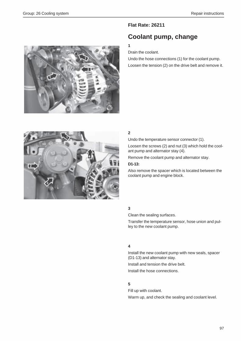
Group: 26 Cooling system Repair instructions
97
Flat Rate: 26211
Coolant pump, change1
Drain the coolant.
Undo the hose connections (1) for the coolant pump.
Loosen the tension (2) on the drive belt and remove it.
2
Undo the temperature sensor connector (1).
Loosen the screws (2) and nut (3) which hold the cool-ant pump and alternator stay (4).
Remove the coolant pump and alternator stay.
D1-13:
Also remove the spacer which is located between thecoolant pump and engine block.
3
Clean the sealing surfaces.
Transfer the temperature sensor, hose union and pul-ley to the new coolant pump.
4
Install the new coolant pump with new seals, spacer(D1-13) and alternator stay.
Install and tension the drive belt.
Install the hose connections.
5
Fill up with coolant.
Warm up, and check the sealing and coolant level.

Repair instructions Group: 30 Electrical system
98
Flat Rate: 32111
Alternator, changing
Current cut off with the main switch
1
Mark and undo all electric connections to the alterna-tor.
2
Loosen the upper fixing nut (1).
Undo the tension screw (2) to release the upper fixingscrew (3) for the alternator.
Unscrew the lower fixing screw (4) and remove the al-ternator.
3
Put the new alternator in position and tighten the lowerfixing screw. Tighten it loosely.
Put the upper fixing screw in position and lightly tight-en the upper fixing nut. Screw the tension screw intothe fixing screw.
Put the drive belt in place and tension it with the ten-sion screw.
IMPORTANT! D1-30, D2-40: Be careful to en-sure that the alternator belt is placed in thegroove closest to the alternator.
4
After checking the drive belt tension, tighten the lowerfixing screw and upper fixing nut.
Install the electric connections on the alternator.
D1-30, D2-40

Group: 30 Electrical system Repair instructions
99
Flat Rate: 33111
Starter motor, changing
Current cut off with the main switch. Alternator re-moved (D1-13).
1
Undo all electric connections (1) to the start solenoid.
2
Undo the screws (2) which hold the starter motor.
Lift the starter motor out.
3
Put the new starter motor in position and fix it with thescrews.
Install the electric connections on the starter motor.
4
Switch the current on and check the starter motorfunction.

Wiring diagram
100
Cable colors
BL = Blue OR = OrangeLBL = Light blue R = RedBN = Brown SB = BlackLBN = Light brown W = WhiteGN = Green Y = YellowGR = Gray
Cable areas in mm2 are specified after the color code in the wiring schedule.
Cable areas not specified = 1.5 mm².
Cables shown with broken lines are not supplied by Volvo Penta.
1. Battery2. Starter motor3. Alternator4. Main switch5. Glow plugs6. Oil pressure monitor7. Stop solenoid8. Coolant temperature monitor9. Coolant temperature sensor10. Circuit breaker, 16 A11. Starter relay12. Glow plug relay13. Charge sensing resistor, 33 Ohm/9W14. Engine speed sensor
Wiring diagramEngine

Wiring diagram
101
1. Instrument illumination2. Tachometer with build-in hours counter (optional)
Or blanking plug3. Connector for connecting extra warning display (optional
equipment)4. Electronic unit (alarm)5. Warning lamp, coolant
temperature6. Warning lamp, oil pressure7. Charge warning lamp8. Indication lamp, glow plugs9. Starter button
10. Press switch. Instrument panel, On/Off11. Connector for connecting extra neutral position switch
(optional equipment)12. Semiconductor diode13. Alarm14. Tumbler switch. Glow plugs – Alarm test/Acknowledgment15. 16-pin connector
Cable colors
BL = BlueBN = BrownGN = GreenGR = GrayOR = OrangePU = PurpleR = RedSB = BlackW = WhiteY = Yellow
Cable areas in mm2 are specified after the colorcode in the wiring schedule.
Instrument panel, alternative “A” ** (without starter switch)

Wiring diagram
102
Spring biased
Spring biased 1. Instrument illumination2. Tachometer with build-in hours counter (optional)
Or blanking plug3. Connector for connecting extra warning display (optional
equipment)4. Electronic unit (alarm)5. Warning lamp, coolant temperature6. Warning lamp, oil pressure7. Charge warning lamp8. Indication lamp, glow plugs9. Switch, instrumentlighting
10. Switch - Alarm test/Acknowledgment11. Key switch12. Alarm13. Connector for connection of neutral positionswitch (optional
equipment)14. 16-pin connector
Cable areas in mm2 are specified after the color code inthe wiring schedule.
Cable colors
BL = BlueBN = BrownGN = GreenGR = GrayOR = OrangeR = RedSB = BlackVO = VioletW = WhiteY = Yellow
Instrument panel, alternative “B” ** (with starter switch)
Technical data
103
Group 20 Technical data
GeneralEngine designation ................................................................. D1-13-A D1-20-A D1-30-A D2-40-ANumber of cylinders ............................................................... 2 3 3 4Cylinder diameter, mm (in) .................................................... 67 (2.64) 67 (2.64) 77 (3.03) 77 (3.03)Stroke length, mm (in) ............................................................ 72 (2.83) 72 (2.83) 81 (3.19) 81 (3.19)Displacement, total litres (cu.in) ............................................. 0.51 (31) 0.76 (46.5) 1.13 (69.1) 1.51 (92.1)Power .................................................................................... See sales literatureIdling speed, rpm ................................................................... 850 ±25Rated speed, rpm................................................................... 3200Compression ratio .................................................................. 23.5:1 23.5:1 23:1 23.5:1Compression at 250 rpm, repair limit, kPa (psi) ...................... 2450 (355)Firing order (highest cyl. No. closest to flywheel) ................... 1-2 1-2-3 1-2-3 1-3-4-2
Direction of rotation see from front ......................................... ClockwiseMax. forward inclination ......................................................... 0o
Max. permissible angle backwards during operation ............... 25o
Max. side angle during operation ............................................ 35o
Valve clearance, idle cold engine: inlet and outlet, mm (in) ...................................................... 0.20 (0.008)Weight, engine without oil and water, kg (lb) ........................... 96 (212) 118 (260) 127 (280) 148 (326)Permitted backpressure in exhaust line, kPa (psi) .................. 20 (2.9)
PistonsMaterial .................................................................................. Aluminium AlloyDiameter, mm (in)D1-13-A, D1-20-A ................................................................... 66.9375 – 66.9525 (2.6353 – 2.6359)
Service limit ...................................................................... 66.7 (2.6260)D1-30-A, D2-40-A ................................................................... 76.932 – 76.947 (3.0288 – 3.0294)
Service limit ...................................................................... 76.7 (3.020)Piston clearance to the cylinder, mm (in)D1-13-A, D1-20-A ................................................................... 0.048 – 0.082 (0.0019 – 0.0032)
Service limit ...................................................................... 0.25 (0,010)D1-30-A, D2-40-A ................................................................... 0.0525 – 0.0865 (0.00210 – 0.00340)
Service limit ...................................................................... 0.25 (0,010)Front marking The ”SHIBAURA” name on the inside of the
piston must be facing the fuel pump on assembly
Piston ringsCompression ring, number ..................................................... 2Oil ring, number ..................................................................... 1Top compression ring:Clearence between groove and ring, all engines, mm (in) ...... 0.06 – 0.10 (0.0024 – 0.0039)
Service limit, all engines , mm (in) .................................... 0.25 (0.0098)Gap of piston ring, mm (in)D1-13-A, D1-20-A ................................................................... 0.13 – 0.25 (0.0051 – 0.0098)D1-30-A, D2-40-A ................................................................... 0.15 – 0.27 (0.0059 – 0.0106)
Service limit, allengines, mm (in) ...................................... 1.0 (0.039)2nd compression ring:Clearence between groove and ring, all engines, mm (in) ...... 0.05 – 0.09 (0.0020 – 0.0035)
Service limit, all engines, mm (in) ..................................... 0.25 (0.0098)Gap of piston ring, mm (in)D1-13-A, D1-20-A ................................................................... 0.10 – 0.22 (0.0039 – 0.0087)D1-30-A, D2-40-A ................................................................... 0.12 – 0.24 (0.0047 – 0.0094)
Service limit, all engines, mm (in) ..................................... 1.0 (0.039)

Technical data
104
Oil ring:Clearence between groove and ring, all engines, mm (in) ...... 0.02 – 0.06 (0.0008 – 0.0024)
Service limit, all engines ................................................... 0.15 (0.0059)Gap of piston ring, mm (in)D1-13-A, D1-20-A ................................................................... 0.10 – 0.30 (0.0039 – 0.0118)D1-30-A, D2-40-A ................................................................... 0.20 – 0.35 (0.0079 – 0.0138)
Service limit, all engines ................................................... 1.0 (0.039)
Piston pinsDiameter, mm (in)D1-13-A, D1-20-A ................................................................... 18.998 – 19.002 (0.7480 – 0.7481)
Service limit ...................................................................... 18.98 (0.7472)D1-30-A, D2-40-A ................................................................... 20.996 – 21.002 (0.8266 – 0.8269)
Service limit ...................................................................... 20.98 (0.826)Clearence between hole and pin, all engines, mm (in) ........... –0.004 to +0.004 (–0.00016 to +0.00016)
Service limit ...................................................................... 0.02 (0.0008)
Cylinder blockDiameter of the bore in the cylinder block, mm (in):D1-13-A, D1-20-A ................................................................... 67.000 – 67.019 (2.6378 – 2.6385)
Service limit ...................................................................... 67.200 (2.6457)D1-30-A, D2-40-A ................................................................... 77.000 – 77.019 (3.0310 – 3.0320)
Service limit ...................................................................... 77.200 (3.0390)Flatness of the top of the cylinder block, mm (in) ................... Less than 0.05 (0.002)
Service limit ...................................................................... 0.12 ( 0.005)
Cylinder headDistortion of the cylinder head, mm (in) .................................. 0.00 – 0.05 (0.000 – 0.002)
Max. service limit, mm (in) ................................................ 0.12 (0.005)Max. limit for regrinding the cylinder head, mm (in) ........... 0.15 (0.006)
Selection of cylinder head gasket:Piston height above top face of cylinder block, mm (in) ......... 0.55 – 0.64 (0.0217 – 0.0252)
Choose gasket with thickness, mm (in) ............................. 1.2 (0.047)Piston height above top face of cylinder block, mm (in) ......... 0.65 – 0.75 (0.0256 – 0.0295)
Choose gasket with thickness, mm (in) ............................. 1.3 (0.051)
Rocker shaftDiameter of the rocker shaft, mm (in):D1-13-A, D1-20-A ................................................................... 9.950 – 9.968 (0.3917 – 0.3924)
Service limit ...................................................................... 9.87 (0.3886)D1-30-A, D2-40-A ................................................................... 11.65 – 11.67 (0.4587 – 0.4595)
Service limit ...................................................................... 11.57 (0.4555)Rocker arm clearance on the rocker shaft, mm (in):D1-13-A, D1-20-A, Min. permissible clearance ....................... 0.032 – 0.065 (0.00126 – 0.00260)D1-30-A, D2-40-A, Min. permissible clearance ....................... 0.032 – 0.068 (0.00126 – 0.00268)Max. permissible clearance, all engines ................................. 0.2 (0.008)

Technical data
105
CrankshaftThrust washers:Standard thickness, mm (in) .................................................. 21.85 – 21.95 (0.8602 – 0.8642)
Service limit ...................................................................... 21.60 (0.8504)NOTE! The thrust washers is machined into the holder for the main bearingCrankshaft end play, mm (in) ................................................. 0.10 – 0.30 (0.0040 – 0.0118)
Service limit ...................................................................... 0.50 (0.0197)Crankshaft deflection, mm (in) ............................................... 0.30 or less (0.0011)
Service limit ...................................................................... 0.06 (0.0023)Front crankshaft bush, diameter in mm (in), bearing journal :
Standard, D1-13-A and D1-20-A ........................................ 42.964 – 42.975 (1.69150 – 1.69193)Service limit ................................................................. 42.90 (1.6890)
Standard, D1-30-A and D2-40-A ........................................ 47.965 – 47.975 (1.88830 – 1.88880)Service limit ................................................................. 47.90 (1.8858)
NOTE! No undersize bush bearing journals are available
Main bearing journalsD1-13-ADiameter in mm (in), standard, bearing journal
No. 1 .................................................. 42.964 – 42.975 (1.69150 – 1.69193)Service limit .................................. 42.90 (1.6890)
No. 2 .................................................. 45.948 – 45.959 (1.80897 – 1.80941)Service limit .................................. 45.90 (1.8071)
NOTE! No undersize main bearing journals are available
D1-20-ADiameter in mm (in), standard, bearing journal
No. 1 and 2 ......................................... 42.964 – 42.975 (1.69150 – 1.69193)Service limit .................................. 42.90 (1.6890)
No. 3 .................................................. 45.948 – 45.959 (1.80897 – 1.80941)Service limit .................................. 45.90 (1.8071)
NOTE! No undersize main bearing journals are available
D1-30-ADiameter in mm (in), standard, bearing journal
No. 1 and 2 ......................................... 47.965 – 47.975 (1.88830 – 1.88880)Service limit .................................. 47.90 (1.8858)
No. 3 .................................................. 47.954 – 47.965 (1.88800 – 1.88830)Service limit .................................. 47.90 (1.8858)
NOTE! No undersize main bearing journals are available
D2-40-ADiameter in mm (in), standard, bearing journal
No. 1, 2 and 3 ..................................... 47.965 – 47.975 (1.88830 – 1.88880)Service limit .................................. 47.90 (1.8858)
No. 4 .................................................. 47.954 – 47.965 (1.88800 – 1.88830)Service limit .................................. 47.90 (1.8858)
NOTE! No undersize main bearing journals are available
Clearance between the main bearing and the mainbearing journal, standard clearance:D1-13-A, Journal No. 1 ........................................................... 0.035 – 0.088 (0.0014 – 0.0035)D1-13-A, Journal No. 2 ........................................................... 0.039 – 0.092 (0.0015 – 0.0036)D1-20-A, Journals No. 1 and 2 ............................................... 0.039 – 0.106 (0.0015 – 0.0042)D1-20-A, Journal No. 3 ........................................................... 0.039 – 0.092 (0.0015 – 0.0036)D1-30-A, D2-40-A ................................................................... 0.039 – 0.106 (0.0015 – 0.0042)Service limit, all engines ........................................................ 0.20 (0.0079)

Technical data
106
Connecting rod bearing journalsD1-13-A, D1-20-ADiameter in mm (in), bearing journal
Standard ...................................................................... 34.964 – 34.975 (1.3765 – 1.3770)Service limit ......................................................... 34.90 (1.3740)
NOTE! No undersize rod bearing journals are available
D1-30-A, D2-40-ADiameter in mm (in), bearing journal
Standard ...................................................................... 40.964 – 40.975 (1.6128 – 1.6132)Service limit ......................................................... 40.90 (1.6102)
NOTE! No undersize rod bearing journals are available
Clearance between the connecting rod bearing and theconnecting rod bearing journal, standard clearance:D1-13-A, D1-20-A ................................................................... 0.031 – 0.079 (0.00122 – 0.00311)D1-30-A, Journals No. 1 and 2 ............................................... 0.039 – 0.092 (0.00150 – 0.00360)D1-30-A, Journal No. 3 ........................................................... 0.029 – 0.082 (0.00110 – 0.00320)D2-40-A.................................................................................. 0.039 – 0.092 (0.00150 –0.00360)Service limit, all engines ........................................................ 0.20 (0.0079)
Connecting rodsPiston pin bearing:Clearance between the piston pin and the piston pinbearing, mm (in) ..................................................................... 0.010 – 0.025 (0.00040 – 0.00099)
Service limit, D1-13-A, D1-20-A ........................................ 0.10 (0.004)Service limit, D1-30-A, D2-40-A ........................................ 0.08 (0.0031)
Connection rod bearing:Clearance between the connecting rod bore andthe connecting rod bearing, mm (in) ....................................... 0.10 – 0.30 (0.004 – 0.012)
Service limit ...................................................................... 0.70 (0.0276)

Technical data
107
CamshaftDrive ...................................................................................... Gear WheelHeight of the camshaft lobe for the inlet and outlet valves,all engines, mm (in) ................................................................ 26.955 – 27.010 (1.0612 – 1.0634)
Service limit ...................................................................... 26.5 (1.0430)Height of the camshaft lobe for the fuel injection pump,all engines, mm (in) ................................................................ 39.900 – 40.100 (1.5709 – 1.5787)
Service limit ...................................................................... 39.8 (1.5669)Height of the camshaft lobe for the fuel priming pump,all engines, mm (in) ................................................................ 27.900 – 28.000 (1.0984 – 1.1024)
Service limit ...................................................................... 27.0 (1.0630)
ValvesInlet
Spindle diameter in mm (in) .................................................... 6.955 – 6.970 (0.27382 – 0.27441)Service limit ...................................................................... 6.89 (0.271)
Valve disc edge in mm (in) ..................................................... 0.925 – 1.075 (0.03642 – 0.04232)Service limit ...................................................................... 0.5 (0.02)
Valve depth below the cylinder head face in mm (in) .............. 0.65 – 0.95 (0.0256 – 0.0374)Service limit ...................................................................... 1.8 (0.071)
Clearance in mm (in), valve spindle guide .............................. 0.025 – 0.052 (0.0010 – 0.0020)Service limit ...................................................................... 0.2 (0.008)
Seat angle in cylinder head .................................................... 45o
Seat contact face in cylinder head ......................................... 1.70 – 2.10 (0.0670 – 0.0830)Service limit, mm (in) ........................................................ 2.5 (0.098)
Valve lash in mm (in), cold engine ......................................... 0.20 (0.008)
Outlet
Spindle diameter in mm (in) .................................................... 6.940 – 6.950 (0.27323 – 0.27362)Service limit, mm (in) ........................................................ 6.84 (0.269)
Valve disc edge in mm (in) ..................................................... 0.925 - 1.075 (0.03642 - 0.04232)Service limit, mm (in) ........................................................ 0.5 (0.02)
Valve depth below the cylinder head face in mm (in) .............. 0.85 – 1.15 (0.0335 – 0.0453)Service limit, mm (in) ........................................................ 1.8 (0.071)
Clearance in mm (in), valve spindle guide .............................. 0.045 – 0.072 (0.0020 – 0.0030)Service limit, mm (in) ........................................................ 0.25 (0.010)
Seat angle in cylinder head .................................................... 45o
Seat contact face in cylinder head ......................................... 1.70 – 2.10 (0.0670 – 0.0830)Service limit, mm (in) ........................................................ 2.5 (0.098)
Valve lash in mm (in), cold engine ......................................... 0.20 (0.008)
Valve springsLength in mm (in) uncompressed ........................................... 35.0 (1.377)Length in mm (in) with 79.4 N (58.56 ft.lbf) compression ....... 30.4 (1.196)
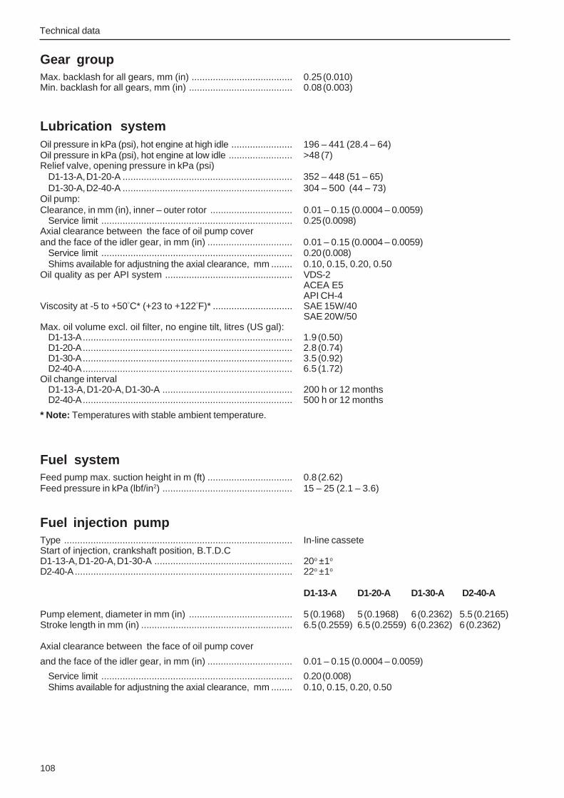
Technical data
108
Gear groupMax. backlash for all gears, mm (in) ...................................... 0.25 (0.010)Min. backlash for all gears, mm (in) ....................................... 0.08 (0.003)
Lubrication systemOil pressure in kPa (psi), hot engine at high idle ....................... 196 – 441 (28.4 – 64)Oil pressure in kPa (psi), hot engine at low idle ........................ >48 (7)Relief valve, opening pressure in kPa (psi)
D1-13-A, D1-20-A ................................................................ 352 – 448 (51 – 65)D1-30-A, D2-40-A ................................................................ 304 – 500 (44 – 73)
Oil pump:Clearance, in mm (in), inner – outer rotor ............................... 0.01 – 0.15 (0.0004 – 0.0059)
Service limit ........................................................................ 0.25 (0.0098)Axial clearance between the face of oil pump coverand the face of the idler gear, in mm (in) ................................ 0.01 – 0.15 (0.0004 – 0.0059)
Service limit ........................................................................ 0.20 (0.008)Shims available for adjustning the axial clearance, mm ........ 0.10, 0.15, 0.20, 0.50
Oil quality as per API system ................................................ VDS-2ACEA E5API CH-4
Viscosity at -5 to +50°C* (+23 to +122°F)* .............................. SAE 15W/40SAE 20W/50
Max. oil volume excl. oil filter, no engine tilt, litres (US gal):D1-13-A............................................................................... 1.9 (0.50)D1-20-A............................................................................... 2.8 (0.74)D1-30-A............................................................................... 3.5 (0.92)D2-40-A............................................................................... 6.5 (1.72)
Oil change intervalD1-13-A, D1-20-A, D1-30-A ................................................. 200 h or 12 monthsD2-40-A............................................................................... 500 h or 12 months
* Note: Temperatures with stable ambient temperature.
Fuel systemFeed pump max. suction height in m (ft) ................................ 0.8 (2.62)Feed pressure in kPa (lbf/in2) ................................................. 15 – 25 (2.1 – 3.6)
Fuel injection pumpType ...................................................................................... In-line casseteStart of injection, crankshaft position, B.T.D.CD1-13-A, D1-20-A, D1-30-A .................................................... 20o ±1o
D2-40-A.................................................................................. 22o ±1o
D1-13-A D1-20-A D1-30-A D2-40-A
Pump element, diameter in mm (in) ....................................... 5 (0.1968) 5 (0.1968) 6 (0.2362) 5.5 (0.2165)Stroke length in mm (in) ......................................................... 6.5 (0.2559) 6.5 (0.2559) 6 (0.2362) 6 (0.2362)
Axial clearance between the face of oil pump cover
and the face of the idler gear, in mm (in) ................................ 0.01 – 0.15 (0.0004 – 0.0059)
Service limit ........................................................................ 0.20 (0.008)Shims available for adjustning the axial clearance, mm ........ 0.10, 0.15, 0.20, 0.50

Technical data
109
InjectorOpening pressure (checking), MPa (psi)D1-13-A, D1-20-A, D2-40-A .................................................... 11.77 (1707)D1-30-A.................................................................................. 14.71 (2133)Jet angle ................................................................................ 4o
Exhaust systemPermitted Max. back pressure in the exhaust line at rated speed,all engines, kPa (psi) ............................................................. 20 (2.9)
Cooling systemType ...................................................................................... Overpressure, closed cooling systemFresh water system volume, approx, litres (US gal)
D1-13-A............................................................................... 2.7 (0.71)D1-20-A............................................................................... 3.0 (0.79)D1-30-A............................................................................... 4.1 (1.08)D2-40-A............................................................................... 6.4 (1.69)
Thermostat, number ............................................................... 1 stThermostat begins to open at ................................................. 90oC (194oF)
fully open at ........................................................................ 105oC (221oF)Coolant, Glycol/water, mixing ratio ......................................... 40/60
Electrical systemSystem voltage ...................................................................... 12 VFuse (automatic) .................................................................... 16 ABattery capacity (starter battery)D1-13-A, D1-20-A, D1-30-A .................................................... 70 AhD2-40-A.................................................................................. 88 AhGlow plug:
rated voltage ....................................................................... 11Vcurrent ................................................................................ 11A
AlternatorOutput voltage at +20oC (+68oF) ............................................. 14,2 ±0,15 VMax. current ........................................................................... 115 ASuppressor capacitor ............................................................. 2.2 mikroF
Starter motorStarter motor, power approx.
D1-13-A, D1-20-A .............................................................. 0.8 kWD1-30-A ............................................................................ 1.1 kWD2-40-A ............................................................................ 1.4 kW

Technical data
110
Tightening torque in Nm (ft.lbf)
Cylinder head*D1-13-A ......................................................................................... 36.5 (26.9)D1-20-A ......................................................................................... 36.5 (26.9)D1-30-A ......................................................................................... 51 (37.6)D2-40-A ......................................................................................... 51 (37.6)
Main bearing:Bolts of the holder for the main bearing ........................................ 23 (16.9)Retaining bolts for the crankshaft ................................................. 27 (19.9)
Connecting Rod:D1-13-A, D1-20-A ......................................................................... 23 (17)D1-30-A, D2-40-A ......................................................................... 32 (23.6)
Front housing .................................................................................... 10 (7.4)Flywheel backplate:
D1-13-A, D1-20-A ......................................................................... 25 (18.4)D1-30-A, D2-40-A ......................................................................... 50 (36.9)
Flywheel housing ............................................................................. 25 (18.4)Flywheel ........................................................................................... 74 (55)Crankshaft pulley:
D1-13-A, D1-20-A ......................................................................... 93 (68.6)D1-30-A, D2-40-A ......................................................................... 123 (90.7)
Flexible coupling .............................................................................. 8.5 – 11.5 (6.3 – 8.5)Suction strainer, oil pump ................................................................. 11 (8)Sump ................................................................................................ 11 (8)Drain plug, sump .............................................................................. 34 (25)Camshaft, setscrews for retainer plate ............................................. 11 (8)Rocker shaft housing:
D1-13-A, D1-20-A ......................................................................... 9.5 (7)D1-30-A, D2-40-A ......................................................................... 23 (17)
Valve mechanism cover:Setscrews ...................................................................................... 11 (8)Cap nuts ........................................................................................ 10 (7.3)
Rocker arm locknut ........................................................................... 14 (10)Fuel injection pump:
Mounting nuts and screws ............................................................ 6 (4.4)Delivery valve holders .................................................................. 42 (31)
Pressure oil pipe (cylinder block–cylinder head) ........................... 12 (9)Injector .............................................................................................. 64 (47.2)Delivery pipe:
D1-13-A, D1-20-A, D2-40-A .......................................................... 20 (14.8)D1-30-A ......................................................................................... 23 (17)
Lock screw (max. fuel volume) ......................................................... 13 – 16 (9.6 – 11.8)Lock screw (speed) .......................................................................... 13 – 16 (9.6 – 11.8)Exhaust manifold .............................................................................. 10 (7.3)Fuel shutoff solenoid ........................................................................ 17 (13)Fuel pump:
Adjustment screw .......................................................................... 2.5 (1.8)Mounting screws ........................................................................... 6 (4.4)
Glow plug .......................................................................................... 11.5 (8.5)Oil pressure switch and adapter ...................................................... 11 (8)Coolant temperature switch ............................................................. 27 (20)Coolant drain plug (plastic) .............................................................. 3 (2.2)Coolant thermostat housing ............................................................. 14 (10)Oil relief valve ................................................................................... 64 (47)Starter motor, contacts ...................................................................... 9.8 – 11.8 (7.2 – 8.7)
* The tightening torque given is the final tightening torque.The cylinder head should be tightened in three stages and in the correct sequence. See tightening procedure.On assembly lubricate cylinder head setscrewes with clean oil.

Technical data
111
Tightening sequence
Cylinder head
General tightening torques in Nm
M5 .................................. 5 NmM6 .................................. 10 NmM7 .................................. 17 NmM8 .................................. 24 NmM10 ................................ 50 NmM12 ................................ 80 NmM14 ................................ 130 Nm
D2-40
D1-20, D1-30
D1-13

Technical data
112
Conversion tableMetric to American or UK units:American or UK to Metric units:
To convert To convertfrom To Multiply by from To Multiply by
Length mm inch 0.03937 inch mm 25.40
cm inch 0.3937 inch cm 2.540
m foot 3.2808 foot m 0.3048
Area mm² sq.in. 0.00155 sq. in. mm² 645.2
m² sq. ft. 10.76 sq. ft. m² 0.093
Volume cm³ cu. in. 0.06102 cu. in. cm³ 16.388
liter, dm³ sq. ft. 0.03531 cu. ft. liter, dm³ 28.320
liter, dm³ cu. in. 61.023 cu. in. liter, dm³ 0.01639
liter, dm³ imp. gallon 0.220 imp. gallon liter, dm³ 4.545
liter, dm³ U.S. gallon 0.2642 U.S. gallon liter, dm³ 3.785
m³ cu. ft. 35.315 cu.ft. m³ 0.0283
Power N lbf 0.2248 lbf N 4.448
Weight kg lb. 2.205 lb. kg 0.454
Power kW hp (metric) 1) 1.36 hp (metric) 1) 1.36 0.735
kW bhp 1.341 bhp kW 0.7457
kW BTU/min 56.87 BTU/min kW 0.0176
Torque Nm lbf ft 0.738 lbf ft Nm 1.356
Pressure Bar psi 14.5038 psi Bar 0.06895
MPa psi 145.038 psi MPa 0.006895
Pa mm Wg 0.102 mm Wg Pa 9.807
Pa in Wc 0.004 in Wg Pa 249.098
kPa in Wg 4.0 in Wg kPa 0.24908
mWg in Wg 39.37 in Wg mWg 0.0254
Energy kJ/kWh BTU/hph 0.697 BTU/hph kJ/kWh 1.435
Work kJ/kg BTU/lb 0.430 BTU/lb kJ/kg 2.326
MJ/kg BTU/lb 430 BTU/lb MJ/kg 0.00233
kJ/kg kcal/kg 0.239 kcal/kg kJ/kg 4.184
Fuel g/kWh g/hph 0.736 g/hph g/kWh 1.36consum- g/kWh lb/hph 0.00162 lb/hph g/kWh 616.78ption
Inertia kgm² lbft² 23.734 lbft² kgm² 0.042
Flow, gas m³/h cu.ft./min. 0.5886 cu.ft./min. m³/h 1.699
Flow,fluid m³/h US gal/min 4.403 US gal/min m³/h 0.2271
Speed m/s ft./s 3.281 ft./s m/s 0.3048mph knot 0.869 knot mph 1.1508
Temp. °F=9/5 x °C+32 °C=5/9 x (°F–32)
1) All power noted in the catalogue refers to metric horsepower.

113
.........................................................................................................................................................................................
.........................................................................................................................................................................................
.........................................................................................................................................................................................
.........................................................................................................................................................................................
.........................................................................................................................................................................................
.........................................................................................................................................................................................
.........................................................................................................................................................................................
.........................................................................................................................................................................................
.........................................................................................................................................................................................
.........................................................................................................................................................................................
.........................................................................................................................................................................................
.........................................................................................................................................................................................
.........................................................................................................................................................................................
.........................................................................................................................................................................................
.........................................................................................................................................................................................
.........................................................................................................................................................................................
.........................................................................................................................................................................................
.........................................................................................................................................................................................
.........................................................................................................................................................................................
.........................................................................................................................................................................................
.........................................................................................................................................................................................
.........................................................................................................................................................................................
.........................................................................................................................................................................................
.........................................................................................................................................................................................
.........................................................................................................................................................................................
.........................................................................................................................................................................................
.........................................................................................................................................................................................
.........................................................................................................................................................................................
.........................................................................................................................................................................................
.........................................................................................................................................................................................
.........................................................................................................................................................................................
.........................................................................................................................................................................................
.........................................................................................................................................................................................
.........................................................................................................................................................................................
Notes

114
.........................................................................................................................................................................................
.........................................................................................................................................................................................
.........................................................................................................................................................................................
.........................................................................................................................................................................................
.........................................................................................................................................................................................
.........................................................................................................................................................................................
.........................................................................................................................................................................................
.........................................................................................................................................................................................
.........................................................................................................................................................................................
.........................................................................................................................................................................................
.........................................................................................................................................................................................
.........................................................................................................................................................................................
.........................................................................................................................................................................................
.........................................................................................................................................................................................
.........................................................................................................................................................................................
.........................................................................................................................................................................................
.........................................................................................................................................................................................
.........................................................................................................................................................................................
.........................................................................................................................................................................................
.........................................................................................................................................................................................
.........................................................................................................................................................................................
.........................................................................................................................................................................................
.........................................................................................................................................................................................
.........................................................................................................................................................................................
.........................................................................................................................................................................................
.........................................................................................................................................................................................
.........................................................................................................................................................................................
.........................................................................................................................................................................................
.........................................................................................................................................................................................
.........................................................................................................................................................................................
.........................................................................................................................................................................................
.........................................................................................................................................................................................
.........................................................................................................................................................................................
.........................................................................................................................................................................................
Notes

115
.........................................................................................................................................................................................
.........................................................................................................................................................................................
.........................................................................................................................................................................................
.........................................................................................................................................................................................
.........................................................................................................................................................................................
.........................................................................................................................................................................................
.........................................................................................................................................................................................
.........................................................................................................................................................................................
.........................................................................................................................................................................................
.........................................................................................................................................................................................
.........................................................................................................................................................................................
.........................................................................................................................................................................................
.........................................................................................................................................................................................
.........................................................................................................................................................................................
.........................................................................................................................................................................................
.........................................................................................................................................................................................
.........................................................................................................................................................................................
.........................................................................................................................................................................................
.........................................................................................................................................................................................
.........................................................................................................................................................................................
.........................................................................................................................................................................................
.........................................................................................................................................................................................
.........................................................................................................................................................................................
.........................................................................................................................................................................................
.........................................................................................................................................................................................
.........................................................................................................................................................................................
.........................................................................................................................................................................................
.........................................................................................................................................................................................
.........................................................................................................................................................................................
.........................................................................................................................................................................................
.........................................................................................................................................................................................
.........................................................................................................................................................................................
.........................................................................................................................................................................................
.........................................................................................................................................................................................
Notes

116
.........................................................................................................................................................................................
.........................................................................................................................................................................................
.........................................................................................................................................................................................
.........................................................................................................................................................................................
.........................................................................................................................................................................................
.........................................................................................................................................................................................
.........................................................................................................................................................................................
.........................................................................................................................................................................................
.........................................................................................................................................................................................
.........................................................................................................................................................................................
.........................................................................................................................................................................................
.........................................................................................................................................................................................
.........................................................................................................................................................................................
.........................................................................................................................................................................................
.........................................................................................................................................................................................
.........................................................................................................................................................................................
.........................................................................................................................................................................................
.........................................................................................................................................................................................
.........................................................................................................................................................................................
.........................................................................................................................................................................................
.........................................................................................................................................................................................
.........................................................................................................................................................................................
.........................................................................................................................................................................................
.........................................................................................................................................................................................
.........................................................................................................................................................................................
.........................................................................................................................................................................................
.........................................................................................................................................................................................
.........................................................................................................................................................................................
.........................................................................................................................................................................................
.........................................................................................................................................................................................
.........................................................................................................................................................................................
.........................................................................................................................................................................................
.........................................................................................................................................................................................
.........................................................................................................................................................................................
References to Service Bulletins
Group No. Date Refers to

Report form
Do you have any comments or complaints about this manual? Please take a copyof this page, write your comments on it and send it to us. The address is at thebottom. We would appreciate it if you were to write in English or Swedish.
From: ............................................................................
......................................................................................
......................................................................................
......................................................................................
Refers to publication: .............................................................................................................................................
Publication no: ............................................................... Date of issue: .................................................................
Suggestion/Motivation: ..........................................................................................................................................
..............................................................................................................................................................................
..............................................................................................................................................................................
..............................................................................................................................................................................
..............................................................................................................................................................................
..............................................................................................................................................................................
..............................................................................................................................................................................
..............................................................................................................................................................................
..............................................................................................................................................................................
Date: ................................................................
Name: ..............................................................
AB Volvo PentaTechnical Information
Dept. 42200SE-405 08 Göteborg
Sweden

774
5200
Eng
lish
03–
2006