world-beam qs18llp series...
TRANSCRIPT
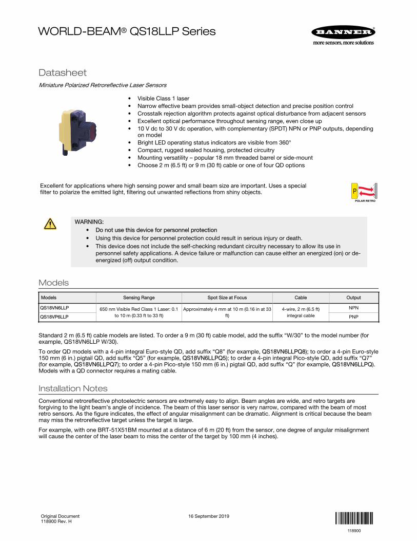
DatasheetMiniature Polarized Retroreflective Laser Sensors
• Visible Class 1 laser• Narrow effective beam provides small-object detection and precise position control• Crosstalk rejection algorithm protects against optical disturbance from adjacent sensors• Excellent optical performance throughout sensing range, even close up• 10 V dc to 30 V dc operation, with complementary (SPDT) NPN or PNP outputs, depending
on model• Bright LED operating status indicators are visible from 360°• Compact, rugged sealed housing, protected circuitry• Mounting versatility – popular 18 mm threaded barrel or side-mount• Choose 2 m (6.5 ft) or 9 m (30 ft) cable or one of four QD options
Excellent for applications where high sensing power and small beam size are important. Uses a specialfilter to polarize the emitted light, filtering out unwanted reflections from shiny objects. P
POLAR RETRO
WARNING:• Do not use this device for personnel protection• Using this device for personnel protection could result in serious injury or death.• This device does not include the self-checking redundant circuitry necessary to allow its use in
personnel safety applications. A device failure or malfunction can cause either an energized (on) or de-energized (off) output condition.
Models
Models Sensing Range Spot Size at Focus Cable Output
QS18VN6LLP 650 nm Visible Red Class 1 Laser: 0.1to 10 m (0.33 ft to 33 ft)
Approximately 4 mm at 10 m (0.16 in at 33ft)
4-wire, 2 m (6.5 ft)integral cable
NPN
QS18VP6LLP PNP
Standard 2 m (6.5 ft) cable models are listed. To order a 9 m (30 ft) cable model, add the suffix “W/30” to the model number (forexample, QS18VN6LLP W/30).
To order QD models with a 4-pin integral Euro-style QD, add suffix “Q8” (for example, QS18VN6LLPQ8); to order a 4-pin Euro-style150 mm (6 in.) pigtail QD, add suffix “Q5” (for example, QS18VN6LLPQ5); to order a 4-pin integral Pico-style QD, add suffix “Q7”(for example, QS18VN6LLPQ7); to order a 4-pin Pico-style 150 mm (6 in.) pigtail QD, add suffix “Q” (for example, QS18VN6LLPQ).Models with a QD connector requires a mating cable.
Installation NotesConventional retroreflective photoelectric sensors are extremely easy to align. Beam angles are wide, and retro targets areforgiving to the light beam’s angle of incidence. The beam of this laser sensor is very narrow, compared with the beam of mostretro sensors. As the figure indicates, the effect of angular misalignment can be dramatic. Alignment is critical because the beammay miss the retroreflective target unless the target is large.
For example, with one BRT-51X51BM mounted at a distance of 6 m (20 ft) from the sensor, one degree of angular misalignmentwill cause the center of the laser beam to miss the center of the target by 100 mm (4 inches).
WORLD-BEAM® QS18LLP Series
Original Document118900 Rev. H
16 September 2019
118900

Sensor-to-Target Distance (X) Beam Displacement (Y) for 1º ofMisalignment
Sensing Distance = X
Ø = Misalignment Angle
Y = X(tan Ø)
Y
Figure 1. Beam displacement per degree of misalignment
1.5 m (5 ft) 25 mm (1 in)
3 m (10 ft) 50 mm (2 in)
6 m (20 ft) 100 mm (4 in)
10 m (33 ft) 150 mm (6 in)
Alignment TipWhen using a small retroreflective target at medium or long range, it is often useful to temporarily attach (or suspend) a strip ofretroreflective tape (for example, BRT-THG-2) along a line that intersects the actual target. The visible red laser beam is easily seenin normal room lighting on such tape. Sight along the beam toward the target (from behind the sensor). Move the sensor to sweepthe laser beam back and forth across the retro tape strip. Use the tape strip to guide the beam onto the target.
Consider using sensor mounting bracket model SMB18SF or SMB3018SC. A swivel bracket can simplify multiple-axis alignment.Alignment is complete when the visible image is centered on the retro target. The perpendicularity of the laser beam to the face ofthe retro target is forgiving, just as it is with a conventional retroreflective sensor.
Effective Beam SizeUnlike conventional retroreflective sensors, the retroreflective laser has the ability to sense relatively small profiles. The tableindicates the diameter of the smallest opaque rod which will reliably break the laser beam at several sensor-to-object distances.These minimum object sizes were measured with the sensor aligned to a BRT-51X51BM reflector and with the sensor set for anexcess gain of about 10X. Flooding effects are possible when the gain is much higher. This means that sensor gain may have to bereduced in some situations in order to reliably detect these minimum object sizes.
Table 1: Minimum object detection size vs distance from sensor
Distance from Sensor to Object Minimum Object Detection Size
0.3 m (1 ft) 2.5 mm (0.10 in)
1.5 m (5 ft) 5.0 mm (0.20 in)
3 m (10 ft) 6.5 mm (0.26 in)
6 m (20 ft) 10 mm (0.40 in)
10 m (33 ft) 13 mm (0.52 in)
CAUTION:• Never stare directly into the sensor lens.• Laser light can damage your eyes.• Avoid placing any mirror-like object in the beam. Never use a mirror as a retroreflective target.
Note that the shape of the beam is elliptical. The minimum object sizes listed assume passage of the rod across the major diameterof the ellipse (worst case). It may be possible to detect objects smaller than the sizes listed if the direction in which the objectspass through the beam can be controlled.
Retroreflector Recommendations• BRT-51X51BM recommended for beam-block applications up to 10 m range.• BRT-TVHG-2X2 recommended for applications up to 1.5 m range. (This retroreflector is an adhesive-backed sealed tape
with micro-prism geometry.)Both reflectors are included with the sensor. See Accessories for information about ordering replacements or other reflectoroptions.
Note: When sensing objects with specular reflections, use the sensor’s side-mounting option to optimizesensing performance.
Wiring DiagramsCabled wiring diagrams are shown.Quick disconnect wiring diagrams are functionally identical.
WORLD-BEAM® QS18LLP Series
2 www.bannerengineering.com - Tel: + 1 888 373 6767 P/N 118900 Rev. H
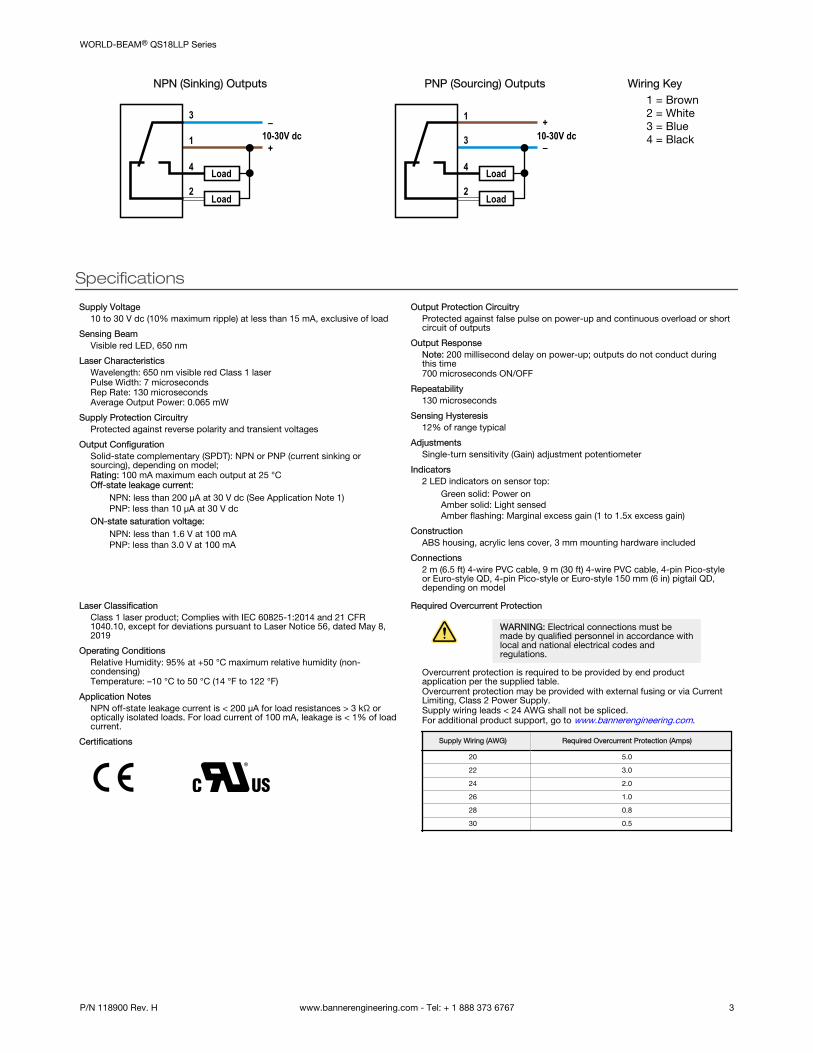
NPN (Sinking) Outputs
10-30V dc–
+1
3
2
4 Load
Load
PNP (Sourcing) Outputs
10-30V dc–
+1
3
2
4 Load
Load
Wiring Key1 = Brown2 = White3 = Blue4 = Black
Specifications
Supply Voltage10 to 30 V dc (10% maximum ripple) at less than 15 mA, exclusive of load
Sensing BeamVisible red LED, 650 nm
Laser CharacteristicsWavelength: 650 nm visible red Class 1 laserPulse Width: 7 microsecondsRep Rate: 130 microsecondsAverage Output Power: 0.065 mW
Supply Protection CircuitryProtected against reverse polarity and transient voltages
Output ConfigurationSolid-state complementary (SPDT): NPN or PNP (current sinking orsourcing), depending on model;Rating: 100 mA maximum each output at 25 °COff-state leakage current:
NPN: less than 200 µA at 30 V dc (See Application Note 1)PNP: less than 10 µA at 30 V dc
ON-state saturation voltage:NPN: less than 1.6 V at 100 mAPNP: less than 3.0 V at 100 mA
Output Protection CircuitryProtected against false pulse on power-up and continuous overload or shortcircuit of outputs
Output ResponseNote: 200 millisecond delay on power-up; outputs do not conduct duringthis time700 microseconds ON/OFF
Repeatability130 microseconds
Sensing Hysteresis12% of range typical
AdjustmentsSingle-turn sensitivity (Gain) adjustment potentiometer
Indicators2 LED indicators on sensor top:
Green solid: Power onAmber solid: Light sensedAmber flashing: Marginal excess gain (1 to 1.5x excess gain)
ConstructionABS housing, acrylic lens cover, 3 mm mounting hardware included
Connections2 m (6.5 ft) 4-wire PVC cable, 9 m (30 ft) 4-wire PVC cable, 4-pin Pico-styleor Euro-style QD, 4-pin Pico-style or Euro-style 150 mm (6 in) pigtail QD,depending on model
Laser ClassificationClass 1 laser product; Complies with IEC 60825-1:2014 and 21 CFR1040.10, except for deviations pursuant to Laser Notice 56, dated May 8,2019
Operating ConditionsRelative Humidity: 95% at +50 °C maximum relative humidity (non-condensing)Temperature: –10 °C to 50 °C (14 °F to 122 °F)
Application NotesNPN off-state leakage current is < 200 µA for load resistances > 3 kΩ oroptically isolated loads. For load current of 100 mA, leakage is < 1% of loadcurrent.
Certifications
Required Overcurrent Protection
WARNING: Electrical connections must bemade by qualified personnel in accordance withlocal and national electrical codes andregulations.
Overcurrent protection is required to be provided by end productapplication per the supplied table.Overcurrent protection may be provided with external fusing or via CurrentLimiting, Class 2 Power Supply.Supply wiring leads < 24 AWG shall not be spliced.For additional product support, go to www.bannerengineering.com.
Supply Wiring (AWG) Required Overcurrent Protection (Amps)
20 5.0
22 3.0
24 2.0
26 1.0
28 0.8
30 0.5
WORLD-BEAM® QS18LLP Series
P/N 118900 Rev. H www.bannerengineering.com - Tel: + 1 888 373 6767 3

Dimensions
Cabled Models
15.0 mm(0.59")
33.5 mm(1.32")
3 mm(0.12")
17.1 mm(0.67")
24.1 mm(0.95")
35.0 mm(1.38")
M18 x 1 Thread Max. Torque 2.3 Nm (20 in-lbs)
ø 3.3 mm (0.13")Max. Torque 0.6 Nm (5 in-lbs)
Pico-Style QD Models
150 mm (6")Pico-Style
Pigtail
41.5 mm(1.63")
Integral4-pin
Pico-Style QD
Euro-Style QD Models
150 mm (6")Euro-Style
Pigtail
49 mm(1.93")
Integral4-pin
Euro-Style QD
Locknut (included with all models)
8.0 mm(0.32")
24.2 mm(0.95")
Washer (included with all models)
1.6 mm (0.06")
Ø 17.8 mm (0.70")
Ø 23.9 mm (0.94")
M3 Hardware Packet Contents:• 2 – M3 x 0.5 x 20 mm SS Screw• 2 – M3 x 0.5 SS Hex Nut• 2 – M3 SS Washer
Description of Class 1 LasersClass 1 lasers are lasers that are safe under reasonably foreseeable conditions of operation, including the use of opticalinstruments for intrabeam viewing.
Reference IEC 60825-1:2014
CAUTION:• Return defective units to the manufacturer.• Use of controls or adjustments or performance of procedures other
than those specified herein may result in hazardous radiationexposure.
• Do not attempt to disassemble this sensor for repair. A defective unitmust be returned to the manufacturer.
For Safe Laser Use (Class 1 or Class 2):
• Do not stare at the laser.• Do not point the laser at a person’s eye.• Mount open laser beam paths either above or below eye level, where practical.• Terminate the beam emitted by the laser product at the end of its useful path.
WORLD-BEAM® QS18LLP Series
4 www.bannerengineering.com - Tel: + 1 888 373 6767 P/N 118900 Rev. H

Accessories
4-Pin Snap-on M8/Pico-Style Cordsets—Single Ended
Model Length Style Dimensions Pinout (Female)
PKG4-2 2 m (6.56 ft) Straight
ø 9.0
32 Typ.
43 1
2
1 = Brown2 = White3 = Blue4 = Black
PKW4Z-2 2 m (6.56 ft) Right-Angle
ø 10.9
29 Typ.
15 Typ.
4-Pin Threaded M12/Euro-Style Cordsets—Single Ended
Model Length Style Dimensions Pinout (Female)
MQDC-406 1.83 m (6 ft)
Straight
44 Typ.
ø 14.5M12 x 1
2
34
1
1 = Brown2 = White3 = Blue4 = Black
MQDC-415 4.57 m (15 ft)
MQDC-430 9.14 m (30 ft)
MQDC-450 15.2 m (50 ft)
MQDC-406RA 1.83 m (6 ft)
Right-Angle
32 Typ.[1.26"]
30 Typ.[1.18"]
ø 14.5 [0.57"]M12 x 1
MQDC-415RA 4.57 m (15 ft)
MQDC-430RA 9.14 m (30 ft)
MQDC-450RA 15.2 m (50 ft)
S15L Series In-Line Sensor Status Indicator
ModelInputType
LED Color Dimensions Female Male Wiring
S15LGYPQ PNP
Power ON =Green
Input Active =Yellow
57.8[2.27]
27.9[1.1]
15.0[0.59]
2
34
11
43
2
1 = Brown, 10 V dc to 30 V dc
2 = White
3 = Blue, dc common
4 = Black, Sensor Input
S15LGYNQ NPN
WORLD-BEAM® QS18LLP Series
P/N 118900 Rev. H www.bannerengineering.com - Tel: + 1 888 373 6767 5

Brackets
SMB18A• Right-angle mounting
bracket with a curved slotfor versatile orientation
• 12-ga. stainless steel• 18 mm sensor mounting
hole• Clearance for M4 (#8)
hardware
30
41
46
A BC
Hole center spacing: A to B = 24.2Hole size: A = ø 4.6, B = 17.0 × 4.6, C = ø 18.5
SMBQS18RA• Right-angle mounting
bracket• 14-ga. 304 stainless steel 42
17
32
A
B
Hole center spacing: A to B=20.3Hole size: A =4.3 × 9.3, B=ø 4.3
SMB312S
• Stainless steel 2-axis, side-mount bracket 46
B
C
A
3220
A = 4.3 × 7.5, B = diam. 3, C = 3 × 15.3
SMB18FA..• Swivel bracket with tilt and pan
movement for precisionadjustment
• Easy sensor mounting toextruded rail T-slots
• Metric and inch size boltsavailable
• 18 mm sensor mounting hole
66
69A
B
Hole size: B=ø 18.1
Model Bolt Thread (A)
SMB18FA 3/8 - 16 × 2 in
SMB18FAM10 M10 - 1.5 × 50
SMB18FAM12 n/a; no bolt included. Mountsdirectly to 12 mm (½ in) rods
SMB46A• 2-piece 12-ga. stainless
steel bracket assembly withprecision sensor alignmentadjustment
• 2 mm hex key included
Hole center spacing: A to B = 18.5, B= 30.5
Hole size: A = ø 6.6, B = 7.1 x 20.3
61 mm
64.5
mm
43 mm
ABB
SMBQS18Y• Die-cast bracket for 18 mm
holes• Includes metal hex nut and
lock washer• Allows ± 8° for cabled
sensors
Hole size: A = ø 15.3
7.8 mm[0.31"]
15.5 mm[0.61"]
19.5 mm[0.77"]
9.8 mm[0.38"]
14.5 mm[0.57"]
25.4 mm[1"]
16.4 mm[0.65"]
24.1 mm[0.94"]
4.5 mm[0.18"]
3.4 mm[0.13"]
2x R24.1 mm[0.95"]
2x 8
38.0 mm[1.50"]
12.0 mm[0.47"]
SMB18SF• 18 mm swivel bracket with M18
× 1 internal thread• Black thermoplastic polyester• Stainless steel swivel locking
hardware included
B
A
51
42
25
Hole center spacing: A = 36.0Hole size: A = ø 5.3, B = ø 18.0
SMBQS18A• Wrap-around protection
bracket• Die-cast bracket• Base fits 18 mm threaded
hole• Metal hex nut, lock washer
and grommet included• Mounting holes specially
designed for QS18AFsensors
Hole size: A = ø 15.3
62
2519
A
WORLD-BEAM® QS18LLP Series
6 www.bannerengineering.com - Tel: + 1 888 373 6767 P/N 118900 Rev. H

Brackets
SMB3018SC• 18 mm swivel side or barrel-
mount bracket• Black reinforced
thermoplastic polyester• Stainless steel swivel
locking hardware included
B
A
67
59
29
Hole center spacing: A = 50.8Hole size: A = ø 7.0, B = ø 18.0
Banner offers a wide selection of high-quality retroreflective targets. See the Accessories section of the current Banner catalog forcomplete information.
Note: NOTE: Polarized sensors require corner cube type retroreflective targets only. Reflectivity factor whencompared with the standard BRT-3 reflector.
Retroreflective Targets
BRT-51X51BM
• Square, acrylic target• Reflectivity Factor: 1.5• Temperature: –20 °C to +50 °C (–4 °F to +122 °F)• Micro-prism geometry• Optional brackets are available• Approximate size: 51 mm × 51 mm
1
10
100
100 mm(4.0")
1000 mm(40")
10000 mm(400")
100000 mm(4000")
10 mm(0.4")
1000
EXCESS
GAIN
DISTANCE
with BRT-51X51BM
BRT-35X35BM
• Square, acrylic target• Reflectivity Factor: 1.2• Temperature:
-20 °C to +60 °C(-4 °F to +140 °F)
• Micro-prism geometry• Approximate size:
35 mm × 35 mm
35 mm (1.4)"
25 mm (0.98")
Clearance for M3
8.4 mm(0.33")
42 mm (1.7")
34 mm (1.3")
Model ReflectivityFactor
Maximum Temperature Size
BRT-TVHG-2X2 0.8 +60 °C (+140 °F) 50 × 50 mm
1
10
100
100 mm(4.0")
1000 mm(40")
10000 mm(400")
100000 mm(4000")
10 mm(0.4")
1000
EXCESS
GAIN
DISTANCE
with BRT-TVHG-2X2
WORLD-BEAM® QS18LLP Series
P/N 118900 Rev. H www.bannerengineering.com - Tel: + 1 888 373 6767 7

Banner Engineering Corp. Limited Warranty
Banner Engineering Corp. warrants its products to be free from defects in material and workmanship for one year following the date of shipment. Banner Engineering Corp. will repair orreplace, free of charge, any product of its manufacture which, at the time it is returned to the factory, is found to have been defective during the warranty period. This warranty does notcover damage or liability for misuse, abuse, or the improper application or installation of the Banner product.
THIS LIMITED WARRANTY IS EXCLUSIVE AND IN LIEU OF ALL OTHER WARRANTIES WHETHER EXPRESS OR IMPLIED (INCLUDING, WITHOUT LIMITATION, ANY WARRANTY OFMERCHANTABILITY OR FITNESS FOR A PARTICULAR PURPOSE), AND WHETHER ARISING UNDER COURSE OF PERFORMANCE, COURSE OF DEALING OR TRADE USAGE.
This Warranty is exclusive and limited to repair or, at the discretion of Banner Engineering Corp., replacement. IN NO EVENT SHALL BANNER ENGINEERING CORP. BE LIABLE TOBUYER OR ANY OTHER PERSON OR ENTITY FOR ANY EXTRA COSTS, EXPENSES, LOSSES, LOSS OF PROFITS, OR ANY INCIDENTAL, CONSEQUENTIAL OR SPECIAL DAMAGESRESULTING FROM ANY PRODUCT DEFECT OR FROM THE USE OR INABILITY TO USE THE PRODUCT, WHETHER ARISING IN CONTRACT OR WARRANTY, STATUTE, TORT,STRICT LIABILITY, NEGLIGENCE, OR OTHERWISE.
Banner Engineering Corp. reserves the right to change, modify or improve the design of the product without assuming any obligations or liabilities relating to any product previouslymanufactured by Banner Engineering Corp. Any misuse, abuse, or improper application or installation of this product or use of the product for personal protection applications when theproduct is identified as not intended for such purposes will void the product warranty. Any modifications to this product without prior express approval by Banner Engineering Corp willvoid the product warranties. All specifications published in this document are subject to change; Banner reserves the right to modify product specifications or update documentation atany time. Specifications and product information in English supersede that which is provided in any other language. For the most recent version of any documentation, refer to: www.bannerengineering.com.
For patent information, see www.bannerengineering.com/patents.
WORLD-BEAM® QS18LLP Series
© Banner Engineering Corp. All rights reserved