world power inherits from leading technology - kva … · user’s handbook world power inherits...
TRANSCRIPT

User’s handbook
World Power Inherits From leading Technology
Lovol Phaser Series, Lovol 1000 Series
Part No.: T768050005
Tianjin Lovol Engines Co.,Ltd.

USER’S HANDBOOK
Lovol Phaser Series, Lovol 1000 Series
3, 4 and 6 cylinder diesel engines for industrial
agricultural and vehicle use
Tianjin Lovol Engines Co., Ltd
Jinwei Road, Beichen District, Tianjin, China
Postcode: 300402
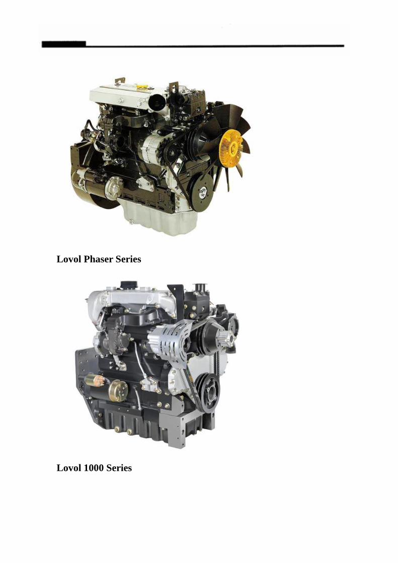
Lovol Phaser Series
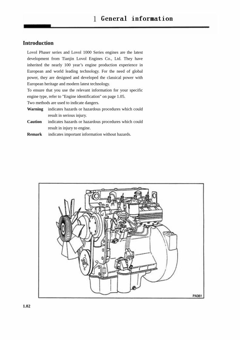
Lovol 1000 Series

EGR engine of Lovol Phaser Series
Engine of Lovol 1000 Series

Contents:
General information…..………………………………………..1
Engine Views……...………………………………………………..2
Instruction for operation.………………………………………….3
Preventive maintenance……………………………………………4
Engine fluids………………………………………………………5
Fault diagnosis…………..………………………………………….6
Engine preservation…………………………………………………7
Parts and service……………………………………………………8
General information…….…………………………………………9
Fuel and injection Pump…………………………………………10
Turbocharger…………………………………………………………11
Hydraulic pump……………………………………………………12
EGR intake system…………………………………………………13

General information 1
Introduction.....................................................................................1.02
How to care for your engine ...........................................................1.03
Safety precautions...........................................................................1.04
Engine identification.......................................................................1.05
Lifting device for engine.................................................................1.06
1.01
Introduction
Lovol Phaser series and Lovol 1000 Series engines are the latest
development from Tianjin Lovol Engines Co., Ltd. They have
inherited the nearly 100 year’s engine production experience in
European and world leading technology. For the need of global
power, they are designed and developed the classical power with
European heritage and modern latest technology.
To ensure that you use the relevant information for your specific
engine type, refer to "Engine identification" on page 1.05.
Two methods are used to indicate dangers.
Warning indicates hazards or hazardous procedures which could
result in serious injury.
Caution indicates hazards or hazardous procedures which could
result in injury to engine.
Remark indicates important information without hazards.
1.02

How to care for your engine
Warning! Read the "Safety precautions" and
remember them. They are given for your protection
and must be applied at all times.
This handbook is to assist you to maintain and operate
your engine correctly.
To obtain the best performance and the longest life
from your engine, you must ensure that the
maintenance operations are done at the intervals
indicated in "Preventive maintenance". If the engine
works in a very dusty environment or other adverse
conditions, certain maintenance intervals will have to
be reduced.
Renew the filter elements and lubricating oil regularly
in order to ensure that the inside of your engine
remains clean.
Ensure that all adjustments and repairs are done by
personnel who have had the correct training.
Lovol distributors have this type of personnel available.
You can also obtain parts and service from your Lovol
distributor.
The left and right sides of the engine are as seen from
the fly wheel.
1.03

Safety precautions
These safety precautions are important. You must refer also to the local regulations in the country of use. Some items only apply to specific applications. � Only use these engines in the type of application for which they have been designed. � Do not change the specification of the engine. � Do not smoke when you put fuel in the tank. � Clean away fuel which has been spilt. Material which has been contaminated by fuel must be moved to a safe
place. � Do not put fuel in the tank while the engine funs (unless it is absolutely necessary). � Do not clean, add lubricating oil, or adjust the engine white it runs (unless you have had the correct training;
even then extreme caution must be used to prevent injury). � Do not make adjustments that you do not understand. � Ensure that the engine does not run in a location where it can cause a concentration of toxic emissions. � Other persons must be kept at a safe distance while the engine or equipment is in operation. � Do not permit loose clothing or long hair near moving parts. � Keep away from moving parts during engine operation. Attention: Some parts cannot be seen clearly while
the engine runs. � Do not operate the engine if a safety guard has been removed. � Do not remove the filler cap of the cooling system while the engine is hot and while the coolant is under
pressure, because dangerous hot coolant can be discharged. � Do not allow sparks or fire near the batteries (especially when the batteries are on charge) because the gases
from the electrolyte are highly flammable. The battery fluid is dangerous to the skin and especially to the eyes.
� Disconnect the battery terminals before a repair is made to the electrical system. � Only one person must control the engine. � Ensure that the engine is operated only from the control panel or from the operator's position. � If your skin comes into contact with high-pressure fuel, obtain medical assistance immediately. � Diesel fuel and lubricating oil (especially used lubricating oil) can damage the skin of certain persons.
Protect your hands with gloves or a special solution to protect the skin. � Do not wear clothing which is contaminated by lubricating oil. Do not put material which is contaminated
with oil into the pockets. � Discard used lubricating oil in a safe place to prevent contamination. � Ensure that the control lever of the transmission drive is in the "out-of-drive" position before the engine is
started. � Attention shall be especially paid when maintenance carried out under bad conditions. � The combustible material of some components of the engine (for example certain seals) can become
extremely dangerous if it is burned. Never allow this burnt material to come into contact with the skin or with the eyes.
� When checking pressure of the parts in water box, safety barrier shall be used to protect the operators. Secure the seal plug of the part to be checked with safety iron wire.
� Don’t contact compressed air with your skin. If your skin comes into contact with compressed air, obtain medical assistance immediately,
� Turbocharger works at high-speed and high temperature. Keep the fingers, tools or other chips away from the inlet and outlet of the Turbocharger and avoid contacts with the hot surface.
� Fit only genuine Lovol parts.
1.04

Engine identification
Phaser series for vehicle use consists of a range of both four and six cylinder engines. Each type of cylinder will have four basic engine types, naturally aspirated, compensated, turbocharged and turbocharged/intercooled. There are different model variations within each cylinder type. Identification of the various models is by a system of similar power output, for example: Phaser 110T – a 4-cylinder engine with a rate output power of 106 horsepower. “T” indicates Turbocharged. Pharser 210Ti --- 6 cylinder engine with a rated output power of 210 horsepower. “Ti” indicates turbocharged and intercooled engine. Phaser110Ti-30、Phaser160Ti-30:
110------ 4-cylinder engine with rated output of 106 hp
160------6-cylinder engine with rated output of 160 hp
T---------Turbocharged engine
Ti—— Turbocharged air-intercooled engine 30 — — In conformance with the Emission requirements of GIII (EU Ⅲ). 1000 series consists of a range of three, four and six cylinder engines. Each type of cylinder will have four basic engine types, naturally aspirated, compensated, turbocharged and turbocharged/intercooled. There are different model variations within each cylinder type. Identification of the various models is by a system of numbers and letters, for example: 1006—6TW 1006--------6 cylinder engine —6--------6 liter engine
T--------Turbocharged TW---------Turbocharged, but with an air to water
intercooler to cool the induction air between the turbocharger and the cylinders 1004D-4TA、1006D-6TA:
1004------4 cylinder engine
D--------- in conformance with the emission
requirement of USA Tier3
—4-------4 liter engine
T------- -Turbocharged
TA------Turbocharged air-intercooled engine Engines used for generator sets have a similar system of model identification, for example: 1003TG、1004TG、1006TAG 1003------3 cylinder engine 1004------4 cylinder engine 1006-------6 cylinder engine T-----------Turbocharged TA---------Turbocharged, but with an air to water intercooler G-----------Generator set In this handbook, the different engine types are indicated by their code letters, which are the first two letters of the engine number as indicated below:
Code letters Engine type BA Three cylinder, naturally aspirated
BB Three cylinder, turbocharged
BC Four cylinder, compensated
BD Three cylinder, turbocharged/intercooled.
BE Three cylinder, turbocharged/intercooled
AA Four cylinder, naturally aspirated
YB Four cylinder, turbocharged
AC Four cylinder, compensated
AD Four cylinder, turbocharged/intercooled.
AE Four cylinder, turbocharged/intercooled.
YA Six cylinder, naturally aspirated
YB Six cylinder, turbocharged
YC Six cylinder, compensated
YD Six cylinder, turbocharged/intercooled.
YE Six cylinder, turbocharged/intercooled.
1.05
Lifting device for engine
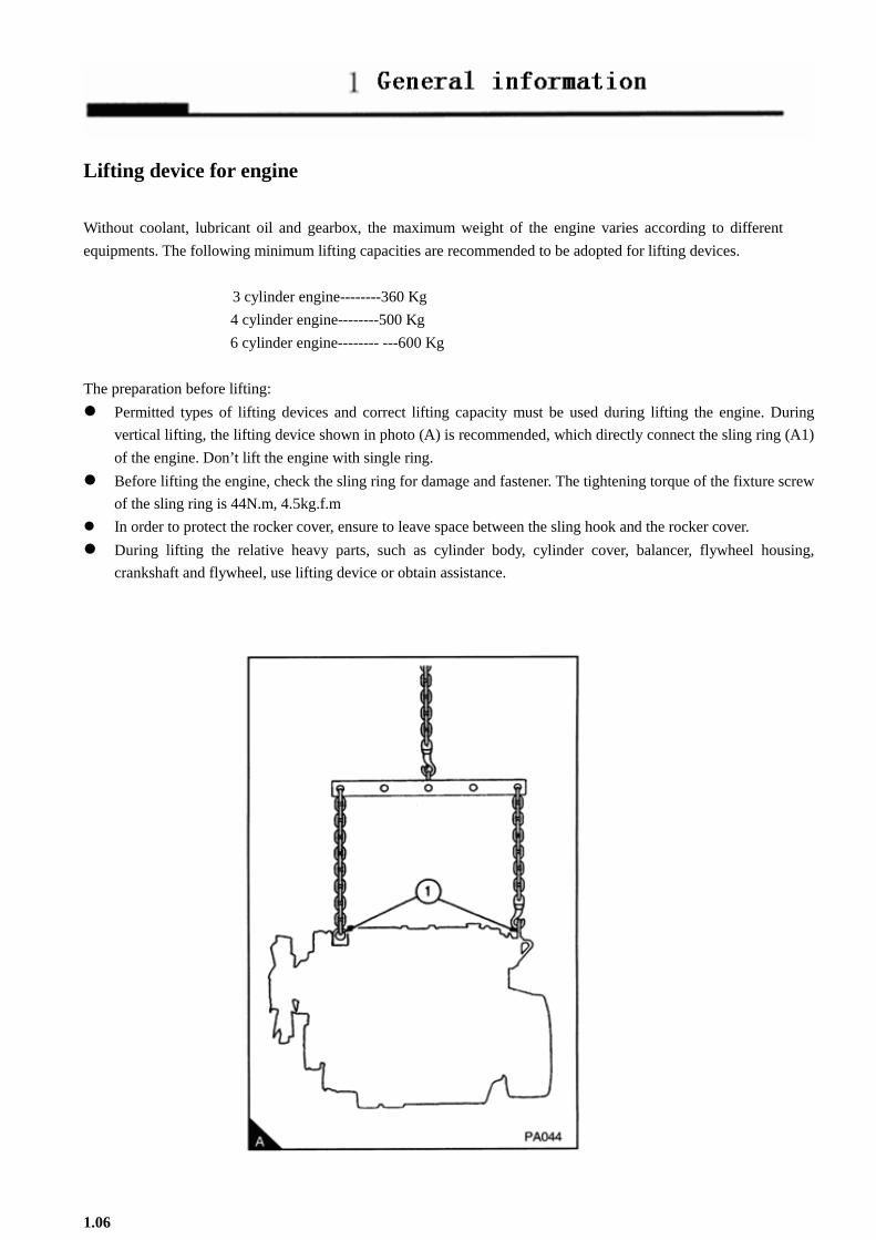
Without coolant, lubricant oil and gearbox, the maximum weight of the engine varies according to different
equipments. The following minimum lifting capacities are recommended to be adopted for lifting devices.
3 cylinder engine--------360 Kg
4 cylinder engine--------500 Kg
6 cylinder engine-------- ---600 Kg
The preparation before lifting:
� Permitted types of lifting devices and correct lifting capacity must be used during lifting the engine. During
vertical lifting, the lifting device shown in photo (A) is recommended, which directly connect the sling ring (A1)
of the engine. Don’t lift the engine with single ring. � Before lifting the engine, check the sling ring for damage and fastener. The tightening torque of the fixture screw
of the sling ring is 44N.m, 4.5kg.f.m � In order to protect the rocker cover, ensure to leave space between the sling hook and the rocker cover.
� During lifting the relative heavy parts, such as cylinder body, cylinder cover, balancer, flywheel housing,
crankshaft and flywheel, use lifting device or obtain assistance.
1.06

Engine Views 2
Introduction….……………………………………………………………………………………………….…2.02
Location of engine parts………………………………………………………………………………………2.03
2.01

Introduction
Lovol Phaser Series and 1000 Series engines are built for specific applications
and the views which follow do not necessarily match your engine specification.
Location of engine parts
Front and left side view of YB engine (A) 1. Filler cap for lubricating oil
2. Fuel filter
3. Lubricating oil cooler
4. Fuel injection pump
5. Lubricating oil dipstick
6. Drain plug for lubricating oil
7. Crankshaft pulley
8. Drive belt
9. Water pump
10. Fan
11. Water outlet
12. Front lift bracket
13. Atomiser
2.02

Rear and right side view of YB engine (A)
14. Induction manifold
15. Alternator
16. Lubricating oil filter
17. Fuel pump
18. Lubricating oil sump
19. Startermotor
20. Flywheel housing
21. Flywheel
22. Turbocharger
23. Exhaust manifold
24. Rear lift bracket
2.03
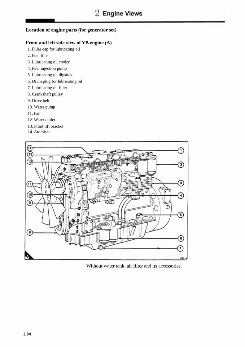
Location of engine parts (for generator set)
Front and left side view of YB engine (A) 1. Filler cap for lubricating oil
2. Fuel filter
3. Lubricating oil cooler
4. Fuel injection pump
5. Lubricating oil dipstick
6. Drain plug for lubricating oil
7. Lubricating oil filter
8. Crankshaft pulley
9. Drive belt
10. Water pump
11. Fan
12. Water outlet
13. Front lift bracket 14. Atomiser
2.04
Without water tank, air filter and its accessories.
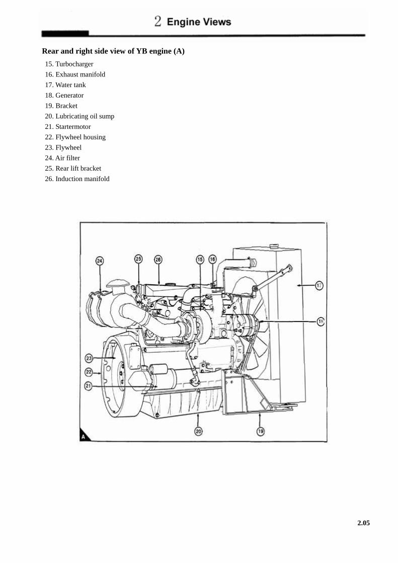
Rear and right side view of YB engine (A)
15. Turbocharger
16. Exhaust manifold
17. Water tank
18. Generator
19. Bracket
20. Lubricating oil sump
21. Startermotor
22. Flywheel housing
23. Flywheel
24. Air filter
25. Rear lift bracket
26. Induction manifold
2.05

Instruction for operation 3
How to start the engine .......................................................................................................................3.02
How to stop the engine ............................................................................................................................................3.04
Adjustment of engine speed range ...........................................................................................................................3.04
Running-in ..........................................................................................................................................3.04
Turbocharged engines.........................................................................................................................3.04
Altitude ...............................................................................................................................................3.04
3.01

How to start the engine
Several factors affect engine start, for example:
� The power of the batteries.
� The performance of the starter motor.
� The viscosity of the lubricating oil.
� The installation of a cold start system.
Diesel engines need a cold starting aid if they are to start in
very cold conditions;
Diesel engines need a starting aid if they are to start in very
cold conditions. Normally, your vehicle or your machine will
be fitted with the correct equipment for your region of
operation.
For the Phaser/1000 Series engines, these systems are:
Fuelled starting aid:
An electrically operated device which ignites a specific
amount of diesel fuel in the induction manifold in order to
heat the induction air.
Attention: If the engine has not run for several weeks, see
"Attention" on page 7.02.
3.02

How to start a warm engine
1. If the engine is equipped with a manual stop control, ensure that
it is in the "run" position.
2. Adjust the engine speed control to the quarter open position.
3. Turn the start key to the "HS" or "S" position to engage the
starter motor;
4. Allow the start key to return to the "Ft" position, as soon as the
engine starts. Always ensure that the engine and starter motor
are stationary before the starter motor is engaged again.
How to start a cold engine
1. If the engine is equipped with a manual stop control, ensure that
it is in the "run" position.
2. Adjust the engine speed control to the maximum speed position.
3. Turn the start key to the "S" position to engage the starter motor.
Allow the key to return to the "R" positron, when the engine
starts. Then adjust the engine speed control to get an even idle
speed.
4. If the engine does not start in 30 seconds, allow the start key to
return to the "R" position for another 30 seconds. Then engage
the starter motor again for a maximum period of 30 seconds.
Attention: Ether type fuels must not be used at the same time as
a fuelled starting aid.
3.03

How to start a cold engine with the fuelled starting aid 1. If the engine is equipped with a manual stop control, ensure that it is in the "run" position.
2. Turn the start key to the “H” position (A) and keep it there for 15 seconds.
3. Adjust the engine speed control to the maximum speed position.
4. Turn the start key to the "HS" to engage the starter motor. Allow the Start key to return to the "R" position when
the engine starts. Then adjust the engine speed control to give an even idle speed;
5. If the engine does not start in 15 seconds, turn the start key to the "H" position and hold it there for 10 seconds.
Then engage the starter motor again.
How to stop the engine Attention: It is recommended that a turbocharged engine is run at approximately 1000 rev/min at a reduced load for
2-3 minutes before it is shut down. This will allow the turbocharger to cool. Adjust the engine speed control to the minimum speed position.
According to the equipment fitted, either turn the engine start key to the "O" position (3.03/A) or operate the manual
stop control. If a manual stop control is used,
Ensure that the control returns to the "run" position after the engine has stopped. Also ensure that the engine start key
is turned to the "O" position.
Adjustment of engine speed range The idle or maximum speed settings must not be changed by the engine operator because this can damage the engine
or transmission. The warranty of the engine can be affected if the seals on the fuel injection pump are broken during
the warranty period by a person who is not approved by Lovol.
Running-in
Attention: � Do not operate the engine at high speeds without a load.
� Do not overload the engine.
A gradual running-in of a new engine or POWER EXCHANGE engine is not necessary. Prolonged operation at light
load during the early life of the engine can cause lubricating oil to enter the exhaust system. Maximum load can be
applied to a new engine as soon as the engine is put into service and the coolant temperature has reached a minimum
of 60℃(140℉).
The engine will benefit if the load is applied as soon as possible after the engine is put into service.
Turbocharged engines Because of the power characteristics of the turbocharged engine it is necessary to maintain a high engine speed when
you climb a gradient. To ensure that the engine is not overloaded at low engine speeds engage a lower gear.
Altitude
If the naturally aspirated engine is to run at an altitude above 600 m (2,000 ft), the fuel delivery can be changed to
reduce fuel consumption and smoke. Lovol can give the percentage of fuel reduction necessary if details of engine
application and ambient conditions are given.
3.04

Preventive maintenance 4
Preventive maintenance period...........................................................................................................4.02
Schedules ............................................................................................................................................4.03
How to drain the cooling system ........................................................................................................4.04
How to check the drive belt(s)............................................................................................................4.05
How to clean the gauze strainer of the fuel lift pump.........................................................................4.06
Fuel pre-filter ......................................................................................................................................4.06
How to renew element(s) of the fuel filter..........................................................................................4.07
How to renew element(s) of the detachable fuel filter .......................................................................4.08
How to renew element(s) of the tank fuel filter..................................................................................4.09
How to renew element(s) of the rapid-detachable fuel filter ..............................................................4.10
Atomiser fault .....................................................................................................................................4.11
How to renew an atomizer..................................................................................................................4.11
How to eliminate air from the fuel system .........................................................................................4.12
How to renew the lubricating oil ........................................................................................................4.17
How to renew the canister(s) of the lubricating oil filter....................................................................4.18
How to renew the closed breather system ..........................................................................................4.19
Air cleaner ..........................................................................................................................................4.20
Air filter ..............................................................................................................................................4.21
Restriction indicator............................................................................................................................4.21
How to check the valve tip clearances................................................................................................4.22
4.01

Preventive maintenance period
Attention::::During driving at short distance and frequently starting and stopping, the number of operation is more
important than driving distance.
These preventive maintenance periods apply to average conditions of operation. Check the periods given by the
manufacturer of the equipment in which the engine is installed. If necessary, use the shorter periods. When the
operation of the engine must conform to the local regulations these periods and procedures may need to be adapted to
ensure correct operation of the engine.
It is good preventive maintenance to check for leakage and loose fasteners at each service.
These maintenance periods apply only to engines that are operated with fuel and lubricating oil which conform to the
specifications given in this handbook.
4.02

Schedules A. First service at 20/40 hours or at 1000/2000 km
B. very day or every 8 hours
C. Every 500 hours or six months
D. Every 1500 km or 250 hours
E. Every 5000 km or 1000 hours
The schedules which follow must be applied at the interval (km, hours or months) which occurs first.
A B C D E Check the amount of coolant Check the concentration of coolant (2)
●
●
●
●
●
Check the drive belt(s) Clean the sediment chamber and the strainer of the fuel lift pump ● ● Check for water in the fuel pre-filter (1) ● Renew the fuel filter element(s) ● Ensure that the atomisers are checked (3) ● Ensure that the idle speed is checked and adjusted, if it is necessary (3) ● Check the amount of lubricating oil in the sump ● ● Check the lubricating oil pressure at the gauge (1) ● ● Renew the engine lubricating oil (4) (5) ● ● Renew the canister(s) of the lubricating oil filter (4) ● Renew the filter of the closed breather system Clean the air cleaner or empty the dust bowl of the air filter ● ● ● - extremely dusty conditions - normal conditions ● Clean or renew the air filter element, if this has not been indicated earlier
●
Ensure that the turbocharger impeller and turbocharger compressor casing are cleaned (2)
● Clean the compressor air filter (1) ● Ensure that the exhauster or compressor (1) is checked (3) ● ● Ensure that valve tip clearances are checked and adjusted, if it is necessary (3) ● Ensure that the alternator, starter motor, etc, are checked (3)
﹙1﹚ If there is one fitted.
﹙2﹚ Antifreeze shall be renewed every 2 years. It must be renewed every 6 month, if using coolant inhibitor to
replace antifreeze.
﹙3﹚ By a person who has had the correct training.
﹙4﹚ The lubricating oil and the filter canister(s) must be renewed every 250 hours or 12 months for applications
where the engine normally runs at full load for periods of more than 20 minutes.
﹙5﹚ The oil change interval will change with the sulphur content of the fuel (see the table below and the Fuel
Specification in section 5). The interval to change the canister of the lubricating oil filter is not affected.
Fuel sulphur content (%>) Oil change interval
﹤0.5 Normal
0.5-1.0 0.75 of normal
﹥1.0 0.50 of normal
4.03

How to drain the cooling system
Attention: Do not drain the coolant while the engine is still hot and the system is under pressure because dangerous
coolant can be discharged.
1. Ensure that the machine is on level ground.
2. Remove the filter cap of the cooling system.
3. Remove the drain plug from the side of the cylinder block (A or B) in order to drain the engine. Ensure that the
drain hole is not restricted.
4. Open the tap or remove the drain plug at the bottom on the radiator in order to drain the radiator. If the radiator
does not have a tap or drain plug, disconnect the hose at the bottom of the radiator.
5. If the lubricating oil cooler (C) is installed the cover of the filter but on the cylinder body, it must be drained and
flushed. For this, disconnect the hoses (C1, C2) on the top of the cooler and flush it by connecting to a tap (C1)
until clean water flow out of the inlet (C2).
Attention::::If the cooling system will not be instilled after flushing, then draining the lubricant oil cooler and instill
165ml (1/3 pints) antifreeze. When the vehicle moving, if water flowing out then this method can prevent freezing.
6. If necessary, flush the system with clean water
7. Install the hose onto the top of the cooler and fasten the clamp.
8. Fit the drain plugs and the filler cap. Close the radiator tap or connect the radiator hose.
9. As for some engine types for agriculture use, one of the cylinder plugs on the cylinder sides are modified into a
switch controlling water release, so as to empty coolant and be suitable for specific agricultural environment.
4.04

How to check the drive belt(s)
Renew a belt if it is worn or damaged. If twin belts are fitted, they must be renewed together.
o ensure maximum belt life, it is recommended that a belt tensioner gauge is used to check the belt tension. Fit the
gauge (A1) at the centre of the longest free length and check the tension. If a "Burroughs" gauge is used, the correct
tension is 355 N 36 kgf. If the tension is 220 N 22 kgf or below, adjust it to 355 N 36 kgf as indicated below:
If a gauge is not available, press down the belt with the thumb at the centre of the longest free length and check the
deflection (B). With moderate thumb pressure - 45N 4.5 kgf - the correct deflection of the belt is 10 mm.
If twin belts are fitted, check/adjust the tension on the tighter belt.
The adjustment of belt tension
1. Loosen the pivot fasteners (B1) of the alternator and the adjustment link fasteners (B2).
2. Change the position of the alternator to give the correct tension. Tighten the pivot fasteners of the alternator and
the adjustment link fasteners.
3. Check the belt tension again to ensure that it is still correct. If a new belt is fitted, the belt tension must be
checked again after the first 20 hours of operation.
4.05

How to clean the gauze strainer of the fuel lift pump
1. Loosen the fastener (A2) and remove the cover and joint (A4) from the top of the fuel lift pump (A3) and remove
the gauze strainer (A1).On some turbocharged 6-cylinder engines, it will be necessary to remove the small heat
shield (A4) which is fitted above the pump. Remove the fuel pump (B), then remove the joint and fuel nut, and
then wash them with clean diesel oil.
2. Carefully wash all the sediment from the lift pump body.
3. Clean the gauze strainer, joint and cover.
4. Assemble the lift pump. Use a good joint and ensure that the lift pump body and the cover are fitted together
correctly. Because leakage at this point will let air into the fuel system. On some turbocharged 6-cylinder engines,
fit the heat shield.
5. Eliminate the air from the fuel system through the filter vent point (see page 4.11).
Fuel pre-filter
If a fuel pre-filter is fitted between the fuel tank and the engine, check the filter bowl for water at regular intervals and
drain as necessary.
4.06
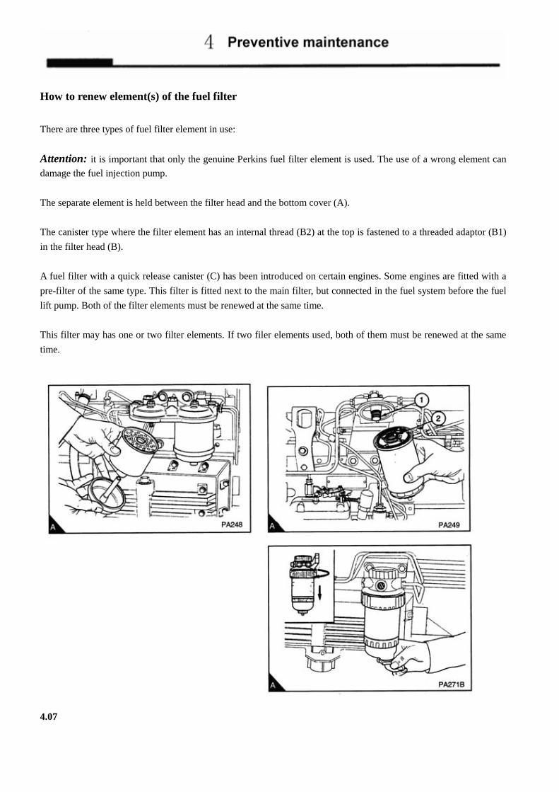
How to renew element(s) of the fuel filter
There are three types of fuel filter element in use:
Attention: it is important that only the genuine Perkins fuel filter element is used. The use of a wrong element can
damage the fuel injection pump.
The separate element is held between the filter head and the bottom cover (A).
The canister type where the filter element has an internal thread (B2) at the top is fastened to a threaded adaptor (B1)
in the filter head (B).
A fuel filter with a quick release canister (C) has been introduced on certain engines. Some engines are fitted with a
pre-filter of the same type. This filter is fitted next to the main filter, but connected in the fuel system before the fuel
lift pump. Both of the filter elements must be renewed at the same time.
This filter may has one or two filter elements. If two filer elements used, both of them must be renewed at the same
time.
4.07

How to renew element(s) of the separate element type
1. Clean the outside surfaces of the fuel filter assembly. If a drain tap (A4) is fitted to the bottom of the filter bowl,
drain the fuel from the filter.
2. Hold the bottom cover of the filter element and release the setscrew (A3) which is fitted through the filter head
(A1) above the centre of each element.
3. Lower the bottom cover of the filter.
4. Remove the element (A5) and discard it.
5. Clean the inside surfaces of the filter head and of the cover.
6. Renew the seals (A2) and (A6) and lightly lubricate them with clean fuel.
7. Put the bottom cover under the new element and hold the element squarely to the filter head. Ensure that the
element is fitted in the centre against the joint in the filter head. With the assembly in this position, engage and
tighten the setscrew.
8. Eliminate the air from the fuel filter (see page 4.12).
4.08

How to renew element(s) of the canister type
1. Thoroughly clean the outside surfaces of the fuel filter assembly.
2. Loosen the drain device at the bottom of the filter (A1) and allow the water/fuel to drain into a suitable container.
3. Use a strap wrench or similar tool to loosen the filter canister and remove the canister.
4. Ensure that the threaded adaptor (B1) is secure in the filter head and that the inside of the head is clean.
5. Lubricate lightly the top seals of the new canister with clean fuel. Fit the new canister to the filter head and
tighten, by hand only.
6. Eliminate the air from the fuel filter (see page 4.12).
4.09

How to renew element(s) of the quick release canister type
Attention: � It is important that only the genuine Lovol fuel filter element is used. The use of a wrong element can damage
the fuel injection pump.
� Do not allow dirt to enter the fuel system. Before a connection is disconnected, clean thoroughly the area around
the connection. After a component has been disconnected, fit a suitable cover to all open connections. 1. Thoroughly clean the outside surfaces of the fuel filter assembly.
2. Loosen the drain device (C5) at the bottom of the canister (C3) and allow the water/fuel to drain into a suitable
container.
Remark: If the drainage equipment has not been installed, then release the cap on the top of the filter (A1). Remove
the nylon block and lower the fuel level, thus the leakage of fuel can be avoided when loosing the clamp ring.
3. Turn the sediment bowl (A4), to the left and remove the bowl, if one is fitted.
4. Turn the clamp ring (A2) to the left and remove the damp ring.
5. Remove the canister from the filter head by a direct pull downwards, and discard the old canister (A3).
6. Ensure the filter head is clean and push the new canister (A3) fully into the filter head.
7. Fit the clamp ring (B1) and turn it fully to the right to fasten the canister (B) to the filter head.
8. Remove the sediment bowl (A4) and thoroughly clean the cover of the bowl.
9. Check the two 'O' ring seals of the sediment bowl cover for damage and, if necessary, renew them.
10. Clean the threads of the sediment bowl fastener, to secure the bowl to the canister turn the bowl fully to the right
and tighten by hand only.
11. If the nylon block used for lowering the oil level has been removed, install it in canister and secure the cap.
12. Eliminate the air from the fuel filter (see page 4.12).
4.10

Atomiser fault Warning!
� If your skin contacts the high-pressure fuel, seek medical assistant immediately.
� Keep away from moving parts during engine operation. Some moving parts cannot be seen clearly while the
engine runs.
An atomiser fault can cause an engine misfire.
In order to find which atomiser is defective, operate the engine at a fast idle speed. Loosen and tighten the union nut
of the high-pressure fuel pipe at each atomiser. When the union nut of the defective atomiser is loosened, it has little
or no effect on the engine speed.
How to renew an atomiser
Attention: Do not allow dirt to enter the fuel system. Before a connection is disconnected, clean thoroughly the area
around the connection. After a component has been disconnected, fit a suitable cover to all open connections.
1. Remove the fuel leak off pipe.
2. Remove the union nuts of the high-pressure pipe from the atomiser and from the fuel injection pump (A1). Do
not bend the pipe. If necessary, remove the pipe clamps.
3. Remove the atomiser flange setscrews and remove the flange (A2), the atomizer (A6) and its seat washer (A7).
Remove the dust seal (A5) and the spacer (A4) and fit the spacer and a new dust seal onto the new atomiser.
4. Put the new atomiser in position with its spacer, new dust seal and a new seat washer. Ensure that the fuel
leak-off connection (A3) is not toward the engine. Fit the flange and engage the flange setscrews. Ensure that the
atomiser is not tilted and tighten the flange setscrews evenly and gradually to 12 Nm 1,2 kgf m..
Attention: Do not tighten the nuts of the high pressure pipes more than the recommended torque tension. If there is
a leakage from the union nut, ensure that the pipe is correctly aligned with the atomiser inlet. Do not tighten the
atomiser union nut more, as this can cause a restriction at the end of the pipe. This can affect the fuel delivery.
5. Fit the high-pressure fuel pipe and tighten the union nuts to 22 Nm 2,2 kgf m.. If necessary, fit the pipe clamps.
6. Renew the aluminum washers and fit the leak-off pipe.
7. Operate the engine and check for leakage of fuel and air.
4.11

How to eliminate air from the fuel system
There are two methods to eliminate air from the fuel system according to the type of pump fitted:
� Bosch rotary EPVE
� Bosch In-line MW
If air enters the fuel system, it must be eliminated before the engine can be started. Air can enter the system if:
� The fuel tank is drained during normal operation.
� The low-pressure fuel pipes are disconnected
� A part of the low-pressure fuel system leaks during engine operation. If air enters the fuel system, it must be
eliminated before the engine can be started. The fuel system must be eliminated before the engine can be started.
In order to eliminate air from the fuel system, proceed as follows:
Attention. The fuel of the engine must not contaminate the engine compartment. A oil-dripping plate shall be put at
the bottom of the engine and remove the used fuel according to the local regulations.
4.12

Air elimination in fuel system of the fuel injection pump fitted with Bosch EPVE 1. Loosen the vent plug on the top of the twin element fuel filter (A1). If a single element filter is used, loosen the
banjo connection bolt which is fitted on the top of the filter (B1).
2. Operate the priming lever on the fuel lift pump (C) until fuel, free from air, comes from the filter vent point.
Tighten the vent plug or the banjo connection bolt.
Remark: If the drive cam of the fuel lift pump is at the point of maximum cam lift, it will not be possible to operate
the priming lever. In this situation, the crankshaft must be turned one revolution.
3. Ensure that the manual stop control is in the "run" position. If an electrical stop control is used, turn the start key
to the "R" position.
4. Loosen the vent screw of the fuel pipe (D1) of the fuel injection pump (B1).
5. Operate the priming lever of the fuel lift pump until fuel, free from air. Conies from the vent screw(s).Tighten
the vent screw(s).
4.13

Attention::::A wrench shall be put on the nut head of fuelled starting aid device to prevent the movement during
tightening or loosing the union nut.
6. If the fuel pipe on the fuelled starting aid has been emptied, loosen the union nut (A1) at the fuelled starting aid
(if one is fitted) and operate the lift pump until fuel, free from air, comes from the connection. Tighten the union
nut at the starting aid. A wrench shall be put on the nut head of fuelled starting aid device to prevent the
movement during tightening or loosing the union nut.
Attention: Do not tighten the nuts of the high pressure pipes more than the recommended torque tension. If there is
a leakage from the union nut, ensure that the pipe is correctly aligned with the atomiser inlet. Do not tighten the
atomiser union nut more, as this can cause a restriction at the end of the pipe. This can affect the fuel delivery.
7. Loosen the union nuts of the high-pressure pipes (B1) at two of the atomisers. If a manual stop control equipped,
ensure that it is in the "run" position. Operate the starter motor until fuel, free from air, comes from the pipe
connections. Tighten the high-pressure pipe connections up to 22N, 22Kg.f.m.
8. The engine is now ready to start.
9. If the engine runs correctly for a short time and then stops or runs roughly, check for air in the fuel system. If
there is air in the fuel system, there is probably a leakage in the low pressure system.
4.14

How to eliminate air from the fuel system of the fuel injection pump fitted with In-line PB
If air enters the fuel system, it must be eliminated before the engine can be started. Air can enter the system if:
� The fuel tank is drained during normal operation.
� The low-pressure fuel pipes are disconnected
� A part of the low-pressure fuel system leaks during engine operation.
In order to eliminate air from the fuel system, proceed as follows:
Attention. The fuel of the engine must not contaminate the engine compartment. An oil-dripping plate shall be put
at the bottom of the engine and remove the used fuel according to the local regulations.
1.Loosen the vent plug on the top of the twin element fuel filter (A1) by turning it 2-3 turns and operate the lift pump
until fuel, free from air, comes from the connection.Tighten the vent plug.
2. Loosen the banjo connection bolt which is fitted on the top of the filter (B1) and operate the lift pump until fuel,
free from air, comes from the connection. Tighten the banjo connection bolt.
3.If the fuel pipe on the fuelled starting aid has been emptied, loosen the union nut (A1) at the fuelled starting aid (if
one is fitted) and operate the lift pump until fuel, free from air, comes from the connection. Tighten the union nut at
the starting aid. A wrench shall be put on the nut head of fuelled starting aid device to prevent the movement during
tightening or loosing the union nut.
4. Ensure that the stop control is in its "run" position and the speed control in its full position. Operate the starter
motor. Reduce the speed of engine when the engine runs. If the engine runs correctly for a short time and then stops
or runs roughly, check for air in the fuel system. If there is air in the fuel system, there is probably a leakage in the
low pressure system.
4.15
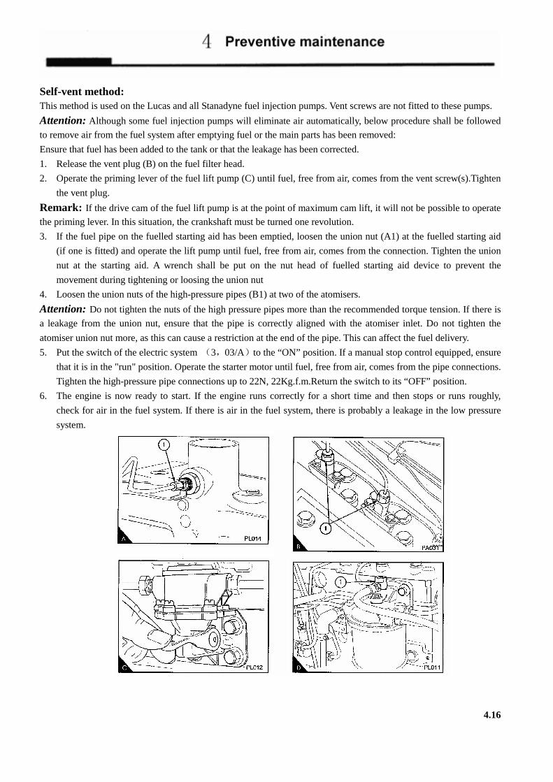
Self-vent method: This method is used on the Lucas and all Stanadyne fuel injection pumps. Vent screws are not fitted to these pumps.
Attention: Although some fuel injection pumps will eliminate air automatically, below procedure shall be followed
to remove air from the fuel system after emptying fuel or the main parts has been removed:
Ensure that fuel has been added to the tank or that the leakage has been corrected.
1. Release the vent plug (B) on the fuel filter head.
2. Operate the priming lever of the fuel lift pump (C) until fuel, free from air, comes from the vent screw(s).Tighten
the vent plug.
Remark: If the drive cam of the fuel lift pump is at the point of maximum cam lift, it will not be possible to operate
the priming lever. In this situation, the crankshaft must be turned one revolution.
3. If the fuel pipe on the fuelled starting aid has been emptied, loosen the union nut (A1) at the fuelled starting aid
(if one is fitted) and operate the lift pump until fuel, free from air, comes from the connection. Tighten the union
nut at the starting aid. A wrench shall be put on the nut head of fuelled starting aid device to prevent the
movement during tightening or loosing the union nut
4. Loosen the union nuts of the high-pressure pipes (B1) at two of the atomisers.
Attention: Do not tighten the nuts of the high pressure pipes more than the recommended torque tension. If there is
a leakage from the union nut, ensure that the pipe is correctly aligned with the atomiser inlet. Do not tighten the
atomiser union nut more, as this can cause a restriction at the end of the pipe. This can affect the fuel delivery.
5. Put the switch of the electric system (3,03/A)to the “ON” position. If a manual stop control equipped, ensure
that it is in the "run" position. Operate the starter motor until fuel, free from air, comes from the pipe connections.
Tighten the high-pressure pipe connections up to 22N, 22Kg.f.m.Return the switch to its “OFF” position.
6. The engine is now ready to start. If the engine runs correctly for a short time and then stops or runs roughly,
check for air in the fuel system. If there is air in the fuel system, there is probably a leakage in the low pressure
system.
4.16

How to renew the lubricating oil 1. Operate the engine until it is warm.
2. Stop the engine, remove the sump drain plug (A3) and its "O" ring and drain the lubricating oil from the sump.
Ensure that the "O" ring is not damaged. Fit the drain plug and its "O" ring and tighten the plug to 34 Nm, 3.5
kgf m.
3. Fill the sump to the "MAX" mark on the dipstick (A2) with new and clean lubricating oil of an approved grade,
see page 5.03.
4.17

How to renew the canister(s) of the lubricating oil filter
Attention: The canister contains a valve and special tube to ensure that lubricating oil does not drain from the filter.
Therefore, ensure that the correct Lovol POWERPART canister is used.
The filter can have one or two canisters. When two canisters are fitted, both must be renewed at the same time.
1. Put a tray under the filter to retain spilt lubricating oil.
2. Remove the filter canister with a strap wrench or similar tool. Ensure that the adaptor (A1) is secure in the filter
head. Then discard the canister.
3. Clean the filter head.
4. Add clean engine lubricating oil to the new canister. Allow the oil enough time to pass through the filter element
5. Lubricate the top of the canister seal with clean engine lubricating oil.
6. Fit the new canister and tighten it by hand only. Do not use a strap wrench.
7. Ensure that there is lubricating oil in the sump. On turbocharged engines, ensure that the engine will not start and
operate the starter motor until oil pressure is obtained. To ensure that the engine will not start, either put the
manual stop control in the "stop" position or disconnect the electrical stop control of the fuel injection pump. Oil
pressure is indicated when the warning light is extinguished or by a reading on the gauge.
8. Operate the engine and check for leakage from the filter. When the engine has cooled, check the oil level on the
dipstick and put more oil into the sump, if necessary.
4.18

How to renew the closed breather system
1. Release the hose clips and remove the breather valve (A1).
Remark::::If it is necessary, remove the breather body (A4) in rocker cover, so as to insert gauze strainer.
2. Remove the plastic gauze strainer (A2) and clean it with clean kerosene.
3. Clean the breather body with clean kerosene.
4. Renew the "O" ring (A3) if necessary.
5. Check that the inside of the breath pipe is clean. If the pipe is not clean, release the flange setscrews and remove
the pipe. Wash the pipe with kerosene and dry it with low pressure air.
6. Install the breather cover back to the breather body and ensure it has been secured installed.
7. Fit the breather pipe and tighten the hose clips.
Remark: Breather body is secured into the rocker cover by thread. If it is necessary to renew the breather assemble,
use a “C” wrench to hold the flange of the bottom to loose the thread.
4.19

Air cleaner
Attention::::Never use gasoline to clean the air cleaner. A typical wet type air cleaner is shown at A.
The wet type air cleaner must be drained at a suitable interval. The container and element (A1) must be cleaned with
kerosene or with another suitable fluid. Do not use gasoline. Check that the seal (A2) is not damaged and renew it, if
necessary. Fill to the indicated level (A2) with dean engine lubricating oil.
4.20

Air filter
Environmental conditions have an important effect on the frequency at which the air filter needs service. Certain air
filters have a separate dust bowl (A1) which must be cleaned at intervals. The amount of dust in the bowl shows if it
has been removed at the correct time for the conditions of operation. Do not let dust completely fill the bowl, because
this will reduce the life of the filter element (A2).
Certain air filters have automatic dust valves (B1) through which dust is expelled from the filter. The rubber dust
valve must be kept clean. Ensure that the sides of the valves close completely together and that they can separate
freely.
If a restriction indicator (C) is fitted, it will indicate precisely when the air filter element needs service. This prevents
the premature removal of the filter element which causes extra cost or late removal to the element which can cause
loss of engine power.
The filter element must be cleaned or renewed according to the manufacturer's recommendations.
Restriction indicator
The restriction indicator for these engines must work at a pressure difference of 508/558 mm of water gauge. It is
fitted on the air filter outlet or between the air filter and the induction manifold.
When the red warning indicator (C1) is seen through the clear panel (C2) after the engine has stopped, the air filter
element must be removed for service.
After a clean element has been fitted, press the rubber bottom (C3) or the button (C4) of the restriction indicator to
reset the red warning indicator.
4.21

How to check the valve tip clearances
Three cylinder engines
The firing sequence of three-cylinder engine is: 1,2,3. When No.1 cylinder is on its upper dead center, you can adjust
the valves indicated with bold font below and turn it with 360 degrees.
Three cylinders: inlet^exhaust^ exhaust^ inlet^ inlet^ exhaust
1 2 3 4 No. of
Cylinder and
Valve 1 2 3 4 5 6 7 8
Valve
I= inlet valve
E=Exhaust valve
I E E I I E E I
IIIInnnnlllleeeetttt eeeexxxxhhhhaaaauuuusssstttt
IIIInnnnlllleeeetttt eeeexxxxhhhhaaaauuuusssstttt
IIIInnnnlllleeeetttt eeeexxxxhhhhaaaauuuusssstttt
4.22

How to check the valve tip clearances
These are checked between the top of the valve stem and the rocker lever (A), with the engine hot or cold. The correct
clearances are 0,20 mm (0,008 in) for inlet valves and 0,45 mm (0.018 in) for exhaust valves. The valve positions are
shown at (B).The order of the valve positions are shown at the table below.
Remark: Number 1 cylinder is at the front of the engine.
Four cylinder engines
1. Turn the crankshaft in the normal direction of rotation until the inlet valve (B8) of number 4 cylinder has just
opened and the exhaust valve (B7) of the same cylinder has not closed completely. Check the clearances of the
valves of number 1 cylinder and adjust them, if it is necessary.
2. Set the valves of number 2 cylinder (B3 and B4) as indicated above for number 4 cylinder. Then check/adjust the
clearances of the valves of number 3 cylinder (B5 and B6).
3. Set the valves of number 1 cylinder (B1 and B2).Then check/adjust the clearances of the valves of number 4
cylinder (B7 and B8).
4. Set the valves of number 3 cylinder (B5 and B6).Then check/adjust the clearances of the valves of number 2
cylinder (B3 and B4).
1 2 3 4 No. of
Cylinder and
Valve 1 2 3 4 5 6 7 8
Valve
I= inlet valve
E=Exhaust valve
I E E I I E E I
4.23

Six cylinder engines
1. Turn the crankshaft in the normal direction of rotation until the inlet valve (A12) of number 6 cylinder has just
opened and the exhaust valve (A11) of the same cylinder has not closed completely. Check the clearances of the
valves (B1 and B2) of number 1 cylinder and adjust them, if it is necessary.
2. Set the valves of number 2 cylinder (A4 and A3) as indicated above for number 6 cylinder. Then check/adjust the
clearances of the valves of number 5 cylinder (A9 and A10).
3. Set the valves of number 4 cylinder (A8 and A7).Then check/adjust the clearances of the valves of number 3
cylinder (A5 and A6).
4. Set the valves of number 1 cylinder (A1 and A2).Then check/adjust the clearances of the valves of number 6
cylinder (A11 and A12).
5. Set the valves of number 5 cylinder (A9 and A10).Then check/adjust the clearances of the valves of number 2
cylinder (A3 and A4).
6. Set the valves of number 3 cylinder (A5 and A6).Then check/adjust the clearances of the valves of number 4
cylinder (A7 and A8).
1 2 3 4 5 6 No. of
Cylinder and
Valve 1 2 3 4 5 6 7 8 9 10 11 12
Valve
I= inlet valve
E=Exhaust valve
I E E 1 1 E E 1 I E E 1
4.24

Fuel/Lubricating oil and Coolant 5
Fuel specification...............................................................................................................................5.02
Lubricating oil specification ..............................................................................................................5.03
Coolant specification .........................................................................................................................5.05
5.01

Fuel specification
To get the correct power and performance from your engine, use good quality fuel. The recommended fuel specification for Lovol engines is indicated below:
Cetane number--------------------50 minimum Viscosity --------------------------2.5/4.5 cent at 40℃ Density-----------------------------0.835/0.855 kg/litre Sulphur-----------------------------0.2% of mass, maximum Distillation-------------------------85% at 350℃
Cetane number indicates ignition performance. A fuel with a low cetane number can cause cold start problems and affect combustion. Viscosity is the resistance to flow and engine performance can be affected if it is outside the limits. Density: A lower density reduces engine power, a higher density increases engine power and exhaust smoke. Sulphur: A high sulphur content (not normally found in Europe, North America or Australasia) can cause engine
wear. Where only high sulphur fuels are available, it is necessary to use a highly alkaline lubricating oil in the engine or to renew the lubricating oil more frequently. See page 4.03
Distillation: This is an indication of the mixture of different hydrocarbons in the fuel. A high ratio of light-weight hydrocarbons can affect the combustion characteristics. Low temperature fuels Special winter fuels may be available for engine operation at temperatures below 0 . These ℃
fuels have a lower viscosity and also limit the wax formation in the fuel at low temperatures. If wax formation occurs, this could stop the fuel flow through the filter.
If you need advice an adjustment to an engine setting or to the lubricating oil change periods which may be necessary because of the standard of available fuel, consult your nearest Lovol distributor. The selection of diesel firstly should be based on the environmental temperature at which diesel engine is to be used. Light diesel with high pour point shall be used in hot south area; light diesel with low pour point shall be used in cold north area. The water content and mechanical impurity shall be as few as possible or else the early construction and part corrosion in filter shall be occurred. The pour point of diesel shall be less then the environmental temperature by at least 6-10 , thus to ensure the ℃
necessary flowability. Under normal environmental temperature, No. 0-10 diesel may be chosen, for example, No. 10 light diesel can be chosen and No. 3-5 diesel can be chosen in cold north. The specifications of light diesel made in china are listed in table 2-1.
Specifications of light diesel
Distillation Temperature Viscosity
Name
Cetane number (not less
than)
50% (not
higher than)
90% (not
higher than)
95% (not
higher than)
。E M 10-6 m2/S
Residual carbon
% ≤
Sulfur % ≤
Ash % ≤
Flash point (close cup) ≥
Pour point ℃ ≤
Mecha- nical
impurity %
Water Content
% Not
larger than
#10 #0
#-10 #-20 #-35
50 50 50 50 50
300 300 300 300 300
355 355 355 355
-
365 365
- -
350
1.2-1.67 1.2-1.67 1.2-1.67 1.15-1.67 1.15-1.67
3-8 3-8 3-8
2.5-8 2.5-8
0.4 0.4 0.3 0.3 0.3
0.2 0.2 0.2 0.2 0.2
.025
.025
.025
.025
.025
60 60 60 60 60
10 0
-10 -20 -35
None None None None None
Trace Trace Trace Trace Trace
The diesel must be clean; a relative long-term sediment or filtration with silk cloth shall be carried out to remove the mechanical impurity before using. 5.02

Lubricating oil specification If you need advice an adjustment to an engine setting or to
the lubricating oil change periods which may be necessary
because of the standard of available fuel, consult your
nearest Lovol distributor.
The selection of diesel firstly should be based on the
environmental temperature at which diesel engine is to be
used.
Use only a good quality lubricating oil to the relevant
specification as shown in the table below.
Attention: The type of lubricating oil to be used may be
affected by the quality of the fuel which is available. For
further details see "Fuel specification" on page 5.02.
Specifications
Engine type API CC/SE
API CC/SE
CCMC
D4
CCMC
D4
GB11123
CF
GB11123
CD
Naturally aspirated • •(1) •
Turbocharger • •
Turbocharged 4 cylinder Phaser engine,
which complies to the European emission
regulations
•
Turbocharged 4 cylinder Phaser engine,
which complies to the European emission
regulations
•
Individual pump engine •
(1)It is not recommended during the first 1000/2000 km
(600/1200 miles) or 20/40 hours of operation, nor for
light-load applications.
5.03
Remark:
Recommended SAE viscosity grades
Ambient temperature
Always ensure that the correct viscosity
grade of lubricating oil is used for the
ambient temperature range in which the
engine will run as shown in photo (A) and
the chart below.

Coolant specification
The quality of the coolant which is used can have a great effect on the efficiency and life of the cooling system. The
recommendations indicated below can help to maintain a good cooling system and to protect it against frost and/or
corrosion. If the correct procedures are not used, Lovol cannot be held responsible for frost or corrosion damage.
1. If it is possible, use clean soft water in the coolant.
2. If antifreeze mixture, other than Lovol antifreeze mixture, is used to prevent frost damage, it must have an
ethanediol base (ethylene glycol) with a corrosion inhibitor. It is recommended that the corrosion inhibitor is of
the sodium nitrite/sodium benzoate type. The antifreeze mixture must be an efficient coolant at all ambient
temperatures and it must provide protection against corrosion. It must also have a specification at least as good as
the requirements of the standards of BS.6580 or MOD AL39.
LOVOL antifreeze exceeds the requirements of the above standards. The quality of the antifreeze coolant must be
checked at least once a year, for example, at the beginning of the cold period. The coolant must be renewed every two
years.
The antifreeze mixture must consist of equal quantities of antifreeze and water. Concentrations of more than 50% of
antifreeze must not be used because these can affect adversely the performance of the coolant.
3. When frost protection is not necessary, it is still an advantage to use an approved antifreeze mixture because this
gives a protection against corrosion and also raises the boiling point of the coolant. If an antifreeze is not used,
add a correct mixture of corrosion inhibitor to the water. Renew the mixture of water and corrosion inhibitor
every six months or check it according to the inhibitor manufacturer's recommendations.
Attention: Certain corrosion inhibitor mixtures could cause damage to some engine components.
When the diesel engine is used at 0℃, the coolant shall be prevented from freezing to lead relative parts burst. The
engine type which use closed cycle cooling system may use antifreeze with property pour point or be added with hot
water, but the water shall be exhausted once stop the car. See table 2-3 for common antifreeze formulas.( for
reference)
During preparing the antifreeze, attention shall be paid to fire safety due to the flammability of ethylene glycol and
alcohol. Before using antifreeze, clean the dirt inside the cooling system preventing the production of new chemical
sediments to influence the cooling effect.
Formula of antifreeze
Name ethylene
glycol Alcohol Glycerol Water Unit
Pour point℃ ≤
ethylene glycol antifreeze
60 55 50 40
40 45 50 60
Volume
percentage
-55 -40 -30 -22
5.04
Fault diagnosis 6
Problems and possible causes...............................................................................6.02
Code list of possible causes..................................................................................6.03
6.01

Problems and possible causes
Possible causes
Problem Checked by the user Checks by the workshop
personnel
The starter motor turns the engine too
slowly
1,2,3,4
The engine does not start / 5,6,7,8,9,10,11,12
13,14,15,17
34,35,36,37,38,40,42,
43,44
The engine is difficult to start 5,7,8,9,10,11,12,13
14,15,16,17,19
34,36,37,38,40,42,43,
44
Not enough power 8,9,10,11,12,13,16,17,
18,19,20,21
34,36,37,38,39,42,43,
44,61,63,64
Misfire
8,9,10,12,13,15,20,22
34,36,37,38,,39,40,41,
43,
High fuel consumption
11,13,15,17,18,19,21,
22
34,36,37,38,39,40,42,
43,44,63
Black exhaust smoke
11,13,15,17,19,21,22 34,36,37,38,39,40,42,
43,44,61,63
Blue or white exhaust smoke
4,15,21,23
36,37,38,39,42,44,45,
52,58,62
The pressure of the lubricating oil is too
low
4,24,25,26
46,47,48,50,51,59
The engine knocks
9,13,15,17,20,22,23
36,37,40,44,46,52,53,
60
The engine runs erratically
7,8,9,10,11,12,13,15,
16,18,20,22,23
34,38,40,41,44,52,60
Vibration 13,18,20,27,28
34,38,40,41,44,52,54
The pressure of the lubricating oil is too
high
4,25
49
The engine temperature is too high 11,13,15,19,27,29,30
32
34,36,37,39,52,55,56,
57,64
High crankcase pressure 31,33
39,42,44,45,52
Bad compression 11,22
37,39,40,42,43,44,45,
53,60
The engine starts and stops 10,11,121
6.02

Code list of possible causes 1. Battery capacity low.
2. Bad electrical connections.
3. Fault in starter motor.
4. Wrong grade of lubricating oil.
5. Starter motor turns engine too slowly.
6. Fuel tank empty.
7. Fault in stop control.
8. Restriction in a fuel pipe.
9. Fault in fuel lift pump.
10. Dirty fuel filter element.
11. Restriction in air filter/cleaner or induction system.
12. Air in fuel system.
13. Fault in atomisers or atomisers of an incorrect type.
14. Cold start system used incorrectly. 15. Fault in cold start system. 6. Restriction in fuel tank vent. 17. Wrong type or grade of fuel used. 18. Restricted movement of engine speed control.
19. Restriction in exhaust pipe. 20. Engine temperature is too high. 21. Engine temperature is too low. 22. Incorrect valve tip clearances. 23. Too much oil or oil of a wrong specification is used
in wet type air cleaner 24. Not enough lubricating oil in sump. 25. Defective gauge 26. Dirty lubricating oil filter element. 27. Fan damaged. 28. Fault in engine mounting or flywheel housing.
29. Too much lubricating oil in sump. 30. Restriction in air or water passages of radiator.
31. Restriction in breather pipe. 32. Insufficient coolant in system. 33. Vacuum pipe leaks or fault in exhauster. 34. Fault in fuel injection pump.
35. Broken drive on fuel injection pump. 36. Timing of fuel injection pump is incorrect. 37. Valve timing is incorrect.
38. Bad compression.
39. Cylinder head gasket leaks,
40. Valves are no! free.
41. Wrong high-pressure pipes.
42. Worn cylinder bores.
43. Leakage between valves and seats.
44. Piston rings are not free or they are worn or broken.
45. Valve stems and/or guides are worn.
46. Crankshaft bearings are worn or damaged.
47. Lubricating oil pump is worn.
48. Relief valve does not close.
49. Relief valve does not open.
50. Relief valve spring is broken.
51. Fault in suction pipe of lubricating oil pump.
52. Piston is damaged.
53. Piston height is incorrect.
54. Flywheel housing or flywheel is not aligned
correctly.
55. Fault in thermostat or thermostat is of an incorrect
type.
56. Restriction in coolant passages.
57. Fault in water pump.
58. Valve stem seal is damaged (if there is one fitted).
59. Restriction in sump strainer.
60. Valve spring is broken.
61. Turbocharger impeller is damaged or dirty.
62. Lubricating oil seal of turbocharger leaks.
63. Induction system leaks (turbocharged engines).
64. Turbocharger waste-gate does not work correctly (if
there is one fitted).
6.03

Engine preservation 7
Introduction...................................................................................................................................7.02
Procedure ......................................................................................................................................7.02
7.01

Introduction:
The recommendations indicated below are designed to prevent damage to the engine when it is withdrawn from
service for a prolonged period.
Procedure:
1. Completely clean the outside of the engine.
2. The system can be kept full with normal fuel but the fuel must be drained and discarded at the end of the storage
period together with the fuel filter element(s).
3. Operate the engine until it is warm. Then correct leakages of fuel, lubricating oil or air. Stop the engine and drain
the lubricating oil from the sump.
4. Renew the canister(s) of the lubricating oil filter.
5. Fill the sump to the full mark on the dipstick with new and clean lubricating oil
6. Drain the cooling system, see page 4 04. In order to protect the cooling system against corrosion, fill it with an
antifreeze mixture with the function of anti-corrosion.
7. Operate the engine for a short period in order to circulate the lubricating oil and the coolant in the engine.
8. Clean the engine breather pipe and seal the end of the pipe.
9. Remove the air filter. Then, if necessary, remove the pipe(s) installed between the air filter and induction
manifold or turbocharger. Seal the manifold or the turbocharger with waterproof tape.
10. Seal the manifold, the vent pipe of the fuel tank or the fuel filler cap with waterproof tape.
11. Disconnect the battery. Then put the battery into safe storage in a fully charged condition. Before the battery is
put into storage, protect its terminals against corrosion.
12. Remove the drive belts and put them into storage.
If the engine protection is done correctly according to the above recommendations, no corrosion damage will
normally occur. Lovol Engines (Tianjin) Co., Ltd are not responsible for damage which may occur when an engine is
in storage after a period in service.
Attention:
After a period in storage, but before the engine is started, operate the starter motor with the engine stop control
(3.03/A) or (3.03/B) in the stop position until oil pressure is indicated. Oil pressure can be indicted when a low
pressure warning light is extinguished. If a solenoid stop control is used on the fuel injection pump, it must be
disconnected for this operation.
7.02
Parts and service 8
Introduction.......................................................................................................................................................8.02
Service literature ............................................................................................................................8.02
Training ..........................................................................................................................................8.02
8.01

Introduction:
If problems occur with your engine or with the components fitted onto it, your Lovol distributor can make the
necessary repairs and will ensure that only the correct parts are fitted and that the work is done correctly.
Service literature:
Workshop manuals and other service publications (including: Parts illustrators, User’s handbook, Service handbook,
Handbook for after service of Lovol engine, CD for service and maintenance or wall charts, etc. ) are available from
your Lovol distributor at a nominal cost.
Training:
Local training for the correct operation, service and overhaul of engines is available at certain Lovol distributors. If
special training is necessary, your Lovol distributor can advise you how to obtain it at the Lovol Engines (Tianjin)
Co., Ltd.
8.02

Engine data 9
Engine data…………………………….……….……………………………9.02
9.01
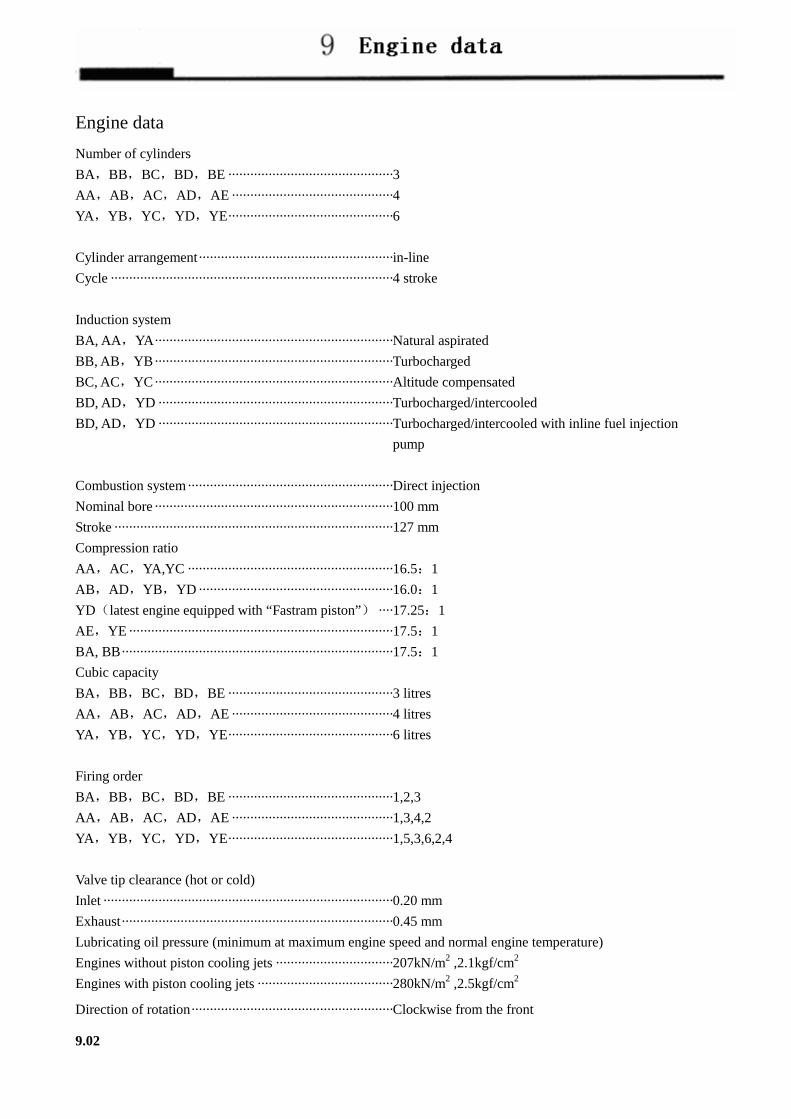
Engine data
Number of cylinders
BA,BB,BC,BD,BE ·············································3
AA,AB,AC,AD,AE ············································4
YA,YB,YC,YD,YE·············································6
Cylinder arrangement·····················································in-line
Cycle ·············································································4 stroke
Induction system
BA, AA,YA·································································Natural aspirated
BB, AB,YB·································································Turbocharged
BC, AC,YC·································································Altitude compensated
BD, AD,YD ································································Turbocharged/intercooled
BD, AD,YD ································································Turbocharged/intercooled with inline fuel injection
pump
Combustion system························································Direct injection
Nominal bore·································································100 mm
Stroke ············································································127 mm
Compression ratio
AA,AC,YA,YC ························································16.5:1
AB,AD,YB,YD·····················································16.0:1
YD(latest engine equipped with “Fastram piston”) ····17.25:1
AE,YE········································································17.5:1
BA, BB··········································································17.5:1
Cubic capacity
BA,BB,BC,BD,BE ·············································3 litres
AA,AB,AC,AD,AE ············································4 litres
YA,YB,YC,YD,YE·············································6 litres
Firing order
BA,BB,BC,BD,BE ·············································1,2,3
AA,AB,AC,AD,AE ············································1,3,4,2
YA,YB,YC,YD,YE·············································1,5,3,6,2,4
Valve tip clearance (hot or cold)
Inlet ···············································································0.20 mm
Exhaust··········································································0.45 mm
Lubricating oil pressure (minimum at maximum engine speed and normal engine temperature)
Engines without piston cooling jets ································207kN/m2 ,2.1kgf/cm2
Engines with piston cooling jets ·····································280kN/m2 ,2.5kgf/cm2
Direction of rotation·······················································Clockwise from the front
9.02

Supplement 10
The Adjustment of the Static Fuel Supply Advance Angle of Linear Pumps (homemade).............10.02
Introduction to Fuel Injection Equipment and Its Air-Discharge of Linear Pumps (homemade)....10.03
PB pump ………………………….……….……………………………… 10.05
Major Technical Data of PB Pump……………….……….………………………10.06
Structure of PB Pump ……………………….……….………………………10.06
Notices on Adjustment and Use of PB Pump………….……….……………………10.07
Structure of RSV Governor…………………….……….………………………10.08
Theory of RSV Governor …………………….……….………………………10.09
Electronically Controlled Governor …………….……….………………………10.10
10.01

The Adjustment of the Static Fuel Pump Timing of Linear Pumps (homemade)
1. Based on the instructions in Page 17A.04 in the Workshop Manual, make marks to indicate the position when
the piston of the first cylinder is at top dead center. The marks should be made on the gear housing cover and the
pulley respectively.
2. Dismount the high-pressure fuel pipes of the first cylinder, and pull the fuel amount control bar to its maximum
position. Turn the crankshaft clockwise viewed from the front end of the engine, until the piston of the first
cylinder reaches TDC.
3. Turn the crankshaft anticlockwise at an angle of over 60°. Then turn the crankshaft clockwise slowly, meanwhile
observe the fuel level in the fuel outlet valve. As soon as the fuel level begins to fluctuate, indicating the
beginning of fuel supply of the first cylinder, you should stop turning the crankshaft. Measure the angle between
the line on the gear housing cover and that on the belt pulley, namely the fuel supply angle. If the latter line is
before the former line, then the fuel is supplied in advance. Otherwise, the fuel supply is retarded.
4. The fuel supply angles of various types of engines are listed below.
Engine type 110Ti 135Ti 160Ti 180Ti 210Ti 230Ti
Pump type 7100 VE 7100 7100 7100 7100
Fuel Pump
Timing
10°±1° 0—1.35 mm 8°±1° 8°±1° 8°±1° 8°±1°
Engine type 1004-4 1004-4T 1006-6T 1004-4TW 1004-4TA 1006-6TW
Pump type AD AD AD VE VE AD
Fuel Pump
Timin
18°±1° 12°±1° 16°±1° 0—0.3 mm 0—0.4 mm 14°±1°
Attention:
For The Fuel Pump Timing of different Engine type, contact perkins lovol Engine (Tianjin) co.,Ltd
5. If the fuel supply angle is not desirable, then it can be adjusted by using the holes on the flange at pump end
after loosening the nuts on the pump bracket and the flange at pump end. The fuel supply angle can be increased
by leaning the pump toward the engine. Otherwise it can be decreased. Corresponding to 1mm distance moved
by the outer edge of the pump flange, the fuel supply angle will be adjusted at about 1°CA.
6. Once the fuel supply angle becomes suitable, the nuts on the flange at the pump end, and the bolts on the pump
bracket, should be screwed down to the required torque. Then repeat step 3 and check the fuel supply angle.
Note: the arc length corresponding to 1°crank angle=πD/360(mm) D—pulley diameter (mm).
10.02

Introduction to the Linear Pumps Made in China
The fuel circuit of the pump is shown in Fig. 1.
The pump camshaft is driven by the engine through the shaft coupling or transmission gears.
Driven by the camshaft, the fuel supply pump sucks the fuel from the tank and supply it to the filter with a pressure of
1.8 to 2.5 kg/cm2. Finally the fuel flows to the fuel housing in the pump body.
The plunger piston is lifted with the turning of the camshaft. As a result the fuel pressure keeps increasing.
The high-pressure fuel is pumped by the fuel pump and injected into the combustion chamber after flowing through
the fuel pipes.
The amount of the fuel supplied by the pump is at least twice the amount of the fuel injected. So the excessive fuel
can flow through the overflow valve to the fuel tank in case the fuel pressure is larger than the required value.
The excessive fuel injected by the injectors (it can also lubricate the injector body) flows to the fuel tank through the
overflow valve on the injector body.
10.03

Air-Discharge of the Fuel System and other Relevant Information
Fuel Low quality fuel will impair the fuel pump and affect the engine performance, so only the fuel recommended by
the engine manufacturer should be used.
Only the clean fuel with right viscosity grade should be used.
� The plunger piston, fuel outlet valve and injectors should be lubricated with fuel of right viscosity grade.
� If the fuel viscosity grade is too low, the components might be choked.
� If the fuel viscosity grade is too high, the combustion will be influenced.
� Due to the extremely small clearance between moving parts, particulates such as dust and iron rust will cause
serious abrasion of the fuel injection system.
In order to keep the fuel clean, the fuel filter should be maintained or replaced regularly. And the fuel tank
should be maintained regularly.
� High concentration of sulfur in the fuel will do harm to the fuel pump. The sulfur dioxide formed through
burning, will combine with water and turn into sulfuric acid, which in turn will corrode the fuel pump and
relevant components. So only the fuel with low concentration of sulfur should be used.
� The water in the fuel will cause the inner part of the fuel pump to corrode, as a result the moving parts might be
choked.
So make sure there is no water in the fuel.
� If there is carbon residual on the injector, the engine performance will be affected. So the fuel which can leave
less carbon residual after burning should be used.
Fuel filter Considering the negative effect of the foreign substance in the fuel, the fuel should be suitably filtered.
Obey the instructions about fuel filter.
Eliminate air from the fuel system and start fueling
After installation of the fuel pump, the air in the fuel system from the fuel tank to injectors should be eliminated
during the initial running. The air in the fuel will decrease the power output and startability, and cause unstable idle
speed.
The fuel lift pump on the fuel supply pump is used to eliminate air from the fuel system during the initial
runnings.
1. Completely loosen the nut on the fuel lift pump.
2. Open the overflow valve or loosen the air-bleed screw on the fuel filter.
3. keep running the fuel lift pump, until there are no bubbles in the fuel flowing out of the overflow valve or
air-bleed screw air-bleed screw。
4. close the overflow valve or fasten the air-bleed screw。
5. Open the overflow valve on the fuel pump and continue to run the fuel lift pump, until there is no bubbles in the
fuel flowing out of the overflow valve.
6. Run the start motor until the engine is started.
Thus the air elimination and start fueling is completed.
10.04
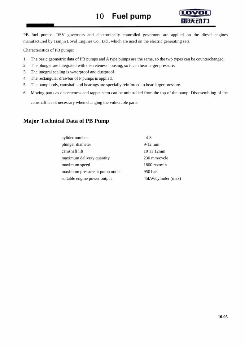
PB fuel pumps, RSV governors and electronically controlled governors are applied on the diesel engines
manufactured by Tianjin Lovol Engines Co., Ltd., which are used on the electric generating sets.
Characteristics of PB pumps:
1. The basic geometric data of PB pumps and A type pumps are the same, so the two types can be counterchanged.
2. The plunger are integrated with discreteness housing, so it can bear larger pressure.
3. The integral sealing is waterproof and dustproof.
4. The rectangular drawbar of P pumps is applied.
5. The pump body, camshaft and bearings are specially reinforced to bear larger pressure.
6. Moving parts as discreteness and tappet stem can be uninstalled from the top of the pump. Disassembling of the
camshaft is not necessary when changing the vulnerable parts.
Major Technical Data of PB Pump
cylider number 4-8
plunger diameter 9-12 mm
camshaft lift 10 11 12mm
maximum delivery quantity 230 mm/cycle
maximum speed 1800 rev/min
maximum pressure at pump outlet 950 bar
suitable engine power output 45kW/cylinder (max)
10.05

Structure of PB Pump::::
10.06
Notices on Adjustment and Use of PB Pump
1. Important adjustment of the pump should be carried out on special test bench according to the technical
documents. And wrong adjustment may cause heavy accidents.
2. When adjust the pump, the temperature of proving oil and diesel should be kept with the range of 35℃ and 40
℃.
3. When adjusting the pretravel, washers of the same thickness should be placed on either side of the plunger.
Otherwise the drawbar will not move smoothly and vibrate, and other malfunction will also occur.
4. The plunger, fuel outlet valve and nozzle coupling elements are of special accuracy, which may be destroyed by
any dust in the fuel. Therefore, the fuel filter and fuel tank should be cleaned periodically to keep the fuel clean.
Forced or splashing lubrication system is applied on the PB pump. In the former case, lubricant need not be filled
at the pump side. However in the two cases, before running the pump (before being mounted on the test bench or
engine), lubricant specified by the engine manufacture should be filled into the pump body until it begin to flow
out of the overflow outlet. If the lubricant is not filled, the bearings, camshaft and pushing rods may be
destroyed.
10.07

Structure of RSV Governor:
10.08

Theory of RSV Governor
RSV governor is of mechanically eccentric type. The governor drawbar device can be simplified into a crank block
device, and the brake device can be simplified into a rolling guide rod device. The pulling force of the spring can be
changed through rotating the spring lever via governor handle, thus the speed range can be changed. When adjusting
the speed, the torque generated by the pulling force of governor spring on the governor lever is equal to the torque of
centrifugal force at the specified speed. The stroke of governor hand lever and flyweight can be transmitted to the
toothed bar through the lever device. The total fuel quantity limit screw and calibrator are mounted in the governor
body. The idle speed stabilizing device is mounted in the rear housing. The adjusting screw on the spring lever is used
to change the speed governing rate within a certain range.
10.09
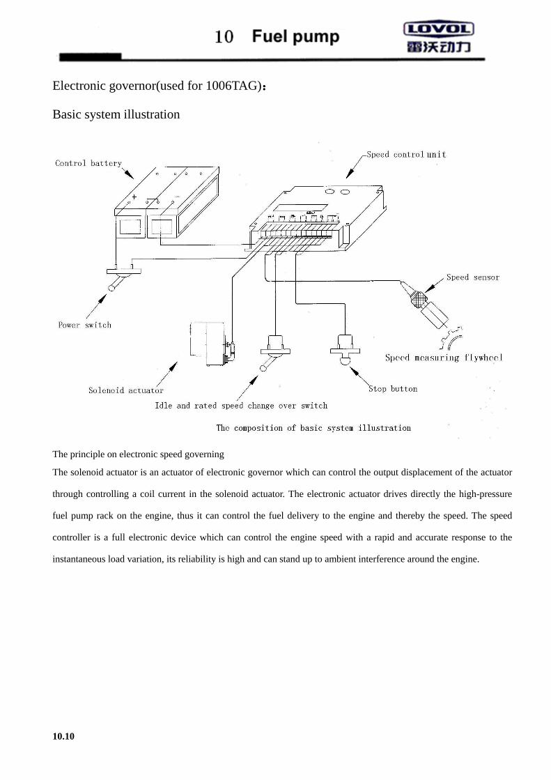
Electronic governor(used for 1006TAG)::::
Basic system illustration
The principle on electronic speed governing
The solenoid actuator is an actuator of electronic governor which can control the output displacement of the actuator
through controlling a coil current in the solenoid actuator. The electronic actuator drives directly the high-pressure
fuel pump rack on the engine, thus it can control the fuel delivery to the engine and thereby the speed. The speed
controller is a full electronic device which can control the engine speed with a rapid and accurate response to the
instantaneous load variation, its reliability is high and can stand up to ambient interference around the engine.
10.10

Turbocharger 11
The Use and Maintenance of the Turbocharger.................................................................... 11.02
Fault diagnosis of Turbocharged engine .....................................................................................11.04
11.01

The use and maintenance of the turbocharger Tianjin Lovol individual pump engine adopts the GARRETT Turbo charger. Then take the Garrett Turbocharger as an example to conduct description. 1.1.1.1. the work principle of a turbocharger 1.1 The work principle and function
� The turbine in the turbocharger is propelled by the engine’s exhaust gas, which in turn drive the compressor. Thus the intake air amount and pressure will be increased and the combustion will be improved.
� The fuel economy will be improved. The exhaust pollution will be decreased. The power output will be enhanced plateau boost.
1.2 lubrication systems the function of the lubrication system � to cool the turbine � to lubricate the gear system � to provide support for the rotor dynamic balance.
1.3 sealing system the sealing of the turbocharger is a dynamic one. The sealing system will function well only when the engine is
running and the air pressure inside the compressor housing and turbine housing is built up and is bigger than the oil pressure of the middle body. All the reasons which lead to fail building up air pressure or larger oil pressure of the middle body than that in both turbine housing may cause a leakage in the turbocharger. 2. Instructions for operation 2.1 The turbocharger should be lubricated with engine lubricating oil, and the oil grade should be CD or above. All
the lubricating oil should flow through a filter which can prevent all particulates with a size of over 20 µm. 2.2 The turbocharger should be lubricated beforehand under the following circumstances: � The engine has been out of work for a long time. � After changing lubricating oil or maintenance (including discharging lubricating oil). Within 3 to 4 seconds after
the engine is started, the oil pressure at the turbocharger inlet should be about 69 kPa (0.7kgf/cm2) 3. When the engine is running with load, the lubricating oil pressure at the turbocharger inlet should be within the range from 196 kPa to 392 kPa (2.11 kgf/cm2 to 4 kgf/cm2) when the engine is running under the maximum torque or at higher speed. 4. The lubricating oil inlet temperature should be usually under 100 , and should not exceed 120℃ ℃ under any cases. 5. Neither liquid sealing strip and joint, nor fluid sealant should be applied to the sealing position. 6. The engine should not be running idle for a long time (over 20 minutes). If the gas pressure in the turbine and compressor is too low, and the turbocharger axle is rotating at a low speed, the lubricating oil in the center housing may leak into the turbine and compressor housing. 7. It is strictly forbidden to run at the mode of “acceleration—stop—running idle”. 8. The engine should first run idle for 3 to 5 minutes to build up the lubricating oil pressure. If the engine is accelerated once it is started, the turbocharger gear will have to work at the maximum speed without being fully lubricated, and as a result it will be damaged. 9. The engine temperature and speed should be decreased gradually from their maximum values within 3 to 5 minutes before the engine is stopped. When the power output or torque output reach their maximum values, the turbocharger temperature and speed is also the highest. Then the engine should run with light duty or idle for a while, meantime the lubricating oil pressure and the amount of air flowing through cooling system should be kept constant. This can prevent the turbocharger from running in short of lubricating oil, and prevent the lubricating oil in the gear and center housing from being burnt and leaving the residue.
11.02

Intake and exhaust system::::
1. The maximum vacuum degree at the compressor inlet when new air filter is applied:
� Medium-duty diesel engine: 3 kPa (0.03 kgf/cm2)
� Heavy-duty diesel engine: 3.5 kPa (0.036 kgf/cm2)
2. When the vacuum degree at the compressor inlet exceeds 6.5 kPa (0.064 kgf/cm2), the air filter canister should be
cleaned or replaced
3. The exhaust pressure at the turbine outlet should not exceed 10 kPa (1kgf/cm2). When exhaust brake is applied, the
exhaust pressure limit should be as specified in the operation manual.
4. the exhaust temperature at the turbine inlet should not exceed 700 ℃。
By-pass valve actuator:
1. he set and calibration of the overall pressure of the by-pass valve actuator is done in the special institutions of the
turbocharger manufacturers, and the customers or other people are not authorized to do so.
2. it is strictly forbidden to use the outer pushing rod of the by-pass valve actuator as a handle when moving the
turbocharger, otherwise the flexibility and durability will be affected.
Daily check
Note: the check should not be done until the engine is cooled down. The engine should not run when the check is in
process to prevent possible casualty.
1. check the pipes connecting the air filter and turbocharger, as well as the turbocharger and intake and exhaust
manifolds.
2. check the fuel inlet and return pipes. Check whether the connecting bolts are loose.
3. check the quality of lubricating oil. Clean or change the canister if necessary.
4. check the air filter. Clean or change the canister if necessary.
5. check the crankcase breather to ensure the pressure in the crankcase is in the normal range.
Periodical maintenance:
The lubricating system, intake and exhaust systems should be maintained periodically according to the
manufacturer’s instruction.
11.03

The fault diagnosis of a turbocharged diesel engine
Do not dismount the turbocharger once you suspect it malfunctions. You are expected to diagnose the fault (refer to the “fault diagnosis table”), find the reason and get rid of the fault. Based on the experiences, to simply replace the turbocharger without finding the reason, will cause the same problems to occur again.
The fault diagnosis of a turbocharged diesel engine
Problem
list of possible causes and solution
no
enoug
h pow
er
black exh
aust sm
oke
high
lub
ricating o
il consu
mption
blu
e or w
hite exh
aust sm
oke
high
noises o
f the tu
rboch
arger
perio
dical noises o
f the tu
rbo
charg
er
fuel leakag
e besid
e the co
mpresso
r
fuel leakag
e besid
e the tu
rbin
e possible causes solution
● ● ● ● ● dirty fuel filter element Change the fuel element according to the
manufacturer's recommendations
● ● ● ● ● ● Unsmooth air flow in
the compressor inlet.
Remove the foreign substance or replace
damaged parts if necessary.
● ● ● Unsmooth air flow in
the compressor outlet.
Remove the foreign substance or replace
damaged parts if necessary.
● ● ● Unsmooth air flow in
the compressor inlet.
Remove foreign substance according to the
Users’ Manual.
●
Air leakage in the pipe
between the air filter
and compressor.
Replace the sealing parts or fasten the fasteners
if necessary.
● ● ● ● ●
Air leakage in the pipe
between the engine and
compressor.
Replace the sealing parts or fasten the fasteners
if necessary.
● ● ● ● ●
Air leakage in the
interface of the cylinder
head and intake
manifold.
Replace the gasket or fasten the fasteners if
necessary.
● ● ● ● ● ●
Unsmooth air flow in
the engine exhaust
manifold.
Remove foreign substance according to the
Users’ Manual.
● ● ●
Unsmooth air flow in
the muffler or exhaust
manifold downstream.
Remove foreign substance or replace degraded
parts according to the Users’ Manual.
11.04

Problems((((continue))))
list of possible causes and solution
no
enoug
h pow
er
black exh
aust sm
oke
high
lub
ricating o
il consu
mption
blu
e or w
hite exh
aust sm
oke
high
noises o
f the tu
rboch
arger
perio
dical noises o
f the tu
rbo
charg
er
fuel leakag
e besid
e the co
mpresso
r
fuel leakag
e besid
e the tu
rbin
e
possible causes possible causes
● ● ● ●
Air leakage in the interface
of the cylinder head and
exhaust manifold.
Replace the gasket or fasten the fasteners if
necessary according to the Users’ Manual..
● ● ● ●
Air leakage in the interface
of the turbine inlet and
intake manifold.
Replace the gasket or fasten the fasteners if
necessary.
●
Air leakage in the exhaust
pipes downstream the
turbine.
Eliminate the phenomenon according to the
Users’ Manual.
● ● ● ●
Unsmooth flow in the fuel
return pipe of the
turbocharger.
Remove the foreign substance or replace the
exhaust pipe.
● ● ● ● Unsmooth flow in the
crankcase breather.
Remove foreign substance according to the
Users’ Manual.
● ● ● ●
Dust or coke accumulation
in the turbocharger center
housing.
Replace the lubricating oil and oil filter.
Overhaul or replace the turbocharger.
● ● Wrong adjustment of the
fuel pump or injectors.
Replace or adjust relevant components
according to the Users’ Manual.
● ● Wrong timing of the engine. Replace abraded parts according to the
Users’ Manual.
● ● ● ● ● ●
Gas blowby caused by the
abrasion of the piston rings
or cylinder liner.
Repair the engine as required.
● ● ● ● ● ● Inner problems of the
engine (gas valve, piston). Repair the engine as required.
● ● ● ● ● ● ● ●
Dust accumulation on the
compressor blades due to
unfiltered air.
Find the reason and eliminate the cause.
Replace the lubricating oil and oil filter.
● ● ● ● ● ● ● ● Damaged turbocharger. Find the reason, and overhaul or replace the
turbocharger as required.
11.05

Main reasons for the damage of turbochargers:
� problems related to lubrication
� foreign matters entering the turbocharger
� the turbocharger running at a high temperature
� poor operation or maintenance
Through carefully checking the damaged parts on turbocharger and correctly analyzing their working conditions, the
causes of the problem can be found definitely. In case it is difficult to find the causes in a short time, it is very
important to look for the reason for every single condition. If the turbocharger is damaged by outer factors, and
repaired without find the cause, then the replaced parts will also be damaged with unknown causes.
The causes will be analyzed below one by one:
1. If air leakage exist between the air outlet and the air inlet of the engine.
2. If air leakage exist at the pipe between the air inlet of the turbo and the air outlet of the exhausting pipe.
3. Too long idle speed。
4. Too high oil pressure or oil level in the crankcase; Restriction in breather pipe of crankcase.
5. Too much blow-by of the engine.
Notes: 1. If a turbocharger has intact appearance, flexible rotor and no impeller friction that suggests that this turbocharger is
in a good status.
2. Most of the returned undamaged turbocharger is unnecessarily changed for misjudgement of oil leakage.
Problems related to lubrication:
1. use of dirty lubricating oil: dirty lubricating oil will cause abrasion of rotating shafts, bearings and bearing saddle
bores. The rotor dynamic balance is affected. And finally the turbocharger is damaged. The lubricating oil will be
contaminated due to following factors:
a. The oil filter does not fulfill requirements, or low quality canister is used.
b. The canister is broken, or the filter in the main oil gallery is choked causing the oil to flow through by-pass
valve.
c. The lubricating oil is not changed as required. And the main oil gallery is not cleaned before the change.
d. Foreign substance enters the oil gallery during replacement of the turbocharger or pre-lubricating.
e. The seal gum or sealing gasket fragments enter the main oil gallery.
2. Shortage of lubricating oil: the function of lubricating oil in the turbocharger is lubricating and cooling. The
shortage of lubricating oil will first affect the cooling capacity, overheat of turbocharger, rotor or bearing damage,
rotor dynamic balance is affected and turbocharger is damaged. Possible reasons for the shortage of lubricating oil:
a. The lubricating oil is not changed as required. The lubricating oil with viscosity grade lower than CD. As a
result, the lubricating oil is coked and malfunctions.
b. The engine stops immediately after running at high load, causing overheat of rotor and bearings, coking of
lubricating oil, and turbocharger damage.
c. The engine runs with load without first running idle after it is started. Or the engine is not pre-lubricated
before the turbocharger is replaced, causing the rotor to run without enough lubricating oil and the
turbocharger is damaged.
d. The fuel pipes or lubricating oil filter is choked, the oil pump malfunctions or the oil pressure is low.
3. Aged lubricating oil cause damage of the turbocharger.
4. Low quality or deteriorated lubricating oil.
11.06
5. Oil leakage: Oil leakage is a common fault. The fault should be diagnosed and eliminated in time to avoid malfunction of
turbocharger. Possible reasons for oil leakage in the turbocharger:
a. The air filter or intake manifold is choked, causing excessive vacuum degree.
b. The fuel return pipe of the turbocharger is bent or damaged.
c. The carbon residual is accumulated in the fuel reservoir of center housing, causing unsmooth fuel return.
Foreign substance entering turbochargers
1. The compressor surface is damaged by foreign substance entering the former through intake manifold or air filter.
a. Poorly sealed intake pipes, causing intake air to enter the compressor without being filtered.
b. The air filter is not replaced as required or poor quality filter element is used, causing poorly filtered air.
c. Foreign substance enters the intake pipes upstream the turbocharger during engine maintenance.
2. The turbine is damaged by foreign substance from exhaust manifolds. For example:
a. Damaged parts fragments enter the turbine with exhaust gas.
b. Something as bolts drop into the exhaust manifolds during its installation, and they enter the turbine with the
exhaust gas.
Every foreign substance will influence the rotor dynamic balance, causing the rotor to choke or rotating shaft to
break.
Abnormal noises 1. gas leakage noises:
� In the engine exhaust manifold, turbocharger turbine and exhaust pipes. Can be judged by exhaust traces.
� In the engine intake manifolds and turbocharger compressor. Can be judged using soap solution.
2. mechanical noises:
� The rotor dynamic balance is damaged.
� The blades touch the turbocharger housing.
� Fasteners become loose.
3. Surge: choked intake air; wrong application.
Excessive temperature
Regardless of engine running or stop, even high-quality lubricating oil will be decomposed due to excessive
temperature. As a result, carbon residual will accumulate in the whole space of center housing, blocking the oil
gallery and even the pipes. Moreover, the lubricating oil will carry the carbon residual to the bearing system,
corroding the working surface, influencing the dynamic balance, and damage the turbocharger. General reasons for
excessive temperature:
� excessive exhaust gas temperature
� excessive lubricating oil temperature
� stopping the engine when it is still hot
� blocked air filter
� use of low quality lubricating oil
11.07

The Use and Maintenance of the Hydraulic Pump................................................................ 10.08
12.01

The use and maintenance of hydraulic pumps
To take YBZ2 series steer vane pump as an example.
As the power source of steering, the pump is suitable for the steering systems of trucks, as well as other vehicles
and industrial machines. The advantages include good performances, compact structure, low noise, reliability and
durability. Flow control valves are installed in the pump, the flow rate of which varies within the range of 10L/min
and 20L/min. safety valves are installed in the return pipes with adjustable pressure, the maximum of which is 14MPa.
The safety valves prevent the hydraulic system from overload.
Working medium: to ensure the performance of the hydraulic pumps, N46 antiwear hydraulic oil or 15W/40CD
diesel is recommended in summer or temperate regions, while N32 antiwear hydraulic oil is recommended in winter
or cold regions. If other types of fluids are used, their viscosity should be within the range of 20 mm2/s ~40mm2/s.
Required working temperature: 10 to 80 .℃
Filter efficiency: 20µm.
1. Use and maintenance: as a high precision pump, steer vane pump should be used and maintained correctly to ensure its performance
and durability. The following rules should be strictly obeyed:
1.1 use correct types of hydraulic oil, otherwise the efficiency and durability of the pump will be affected.
1.2 The hydraulic oil must be kept clean. The hydraulic oil should be changed, and oil tank, filter and pipes
should be cleaned carefully after 2500km running of new vehicles. Thereafter the hydraulic oil should be
changed for every 20000km running. Meantime the oil should be checked frequently, and the filter
elements should be replaced periodically.
1.3 The vacuum of the oil suction parts of the pump should be no less than 15kPa.
1.4 Frequently check for leakage, abnormal running, collision or noises, to find and eliminate malfunctions in
time.
2. Common faults and solutions:
phenomena reasons Solutions The filters or pipes are blocked. Replace the filter element, clean the pipes or
change the fluid. Leakage in the pipes causes air to enter the pump. Check or fasten relevant threaded
connections or change sealing parts to prevent air from intruding. Open the junction of fuel pipe to deair.
Enlarged clearance between worn components causes leakage.
Check relevant parts and repair.
Too low oil viscosity. Use fluids with suitable viscosity.
the oil is not sucked or pressurized (the actuator does not work)
Too low oil level. Add oil to required level. oil leakage in interfaces
Loosened joints or damaged sealing parts. Fasten threaded connections or replace sealing parts.
Air intrudes the pump. Check whether there is leakage in relevant parts. Add oil in the junctions, decreased noise will indicate a leakage. Fasten the junctions or replace sealing parts.
loud noises
Serious resistance or even jam in the suction pipe.
Check the flow and capacity of the filter.
3. Preservation The blades should be stored in a dry warehouse without corrosive gas. It is strictly forbidden to store them in
high temperature or the temperature under -20 for a long time, in order to prevent rubber parts from ageing. Often ℃
check for possible corrosion. Replace anti-corrosive fluids if necessary.
12.02
EGR induction system 13
Work principle of EGR induction system……………………………………………………………..13.02
Schematic diagram of EGR electric units……………………………………………………………..13.03
Introduction of ERG engine elements…………………………………………………………………13.05
Installation and dismantlement of EGR valve and EGR cooler……………………………………..13.09
Fault display – fault indicator………………………………………………………………………….13.10
13.01
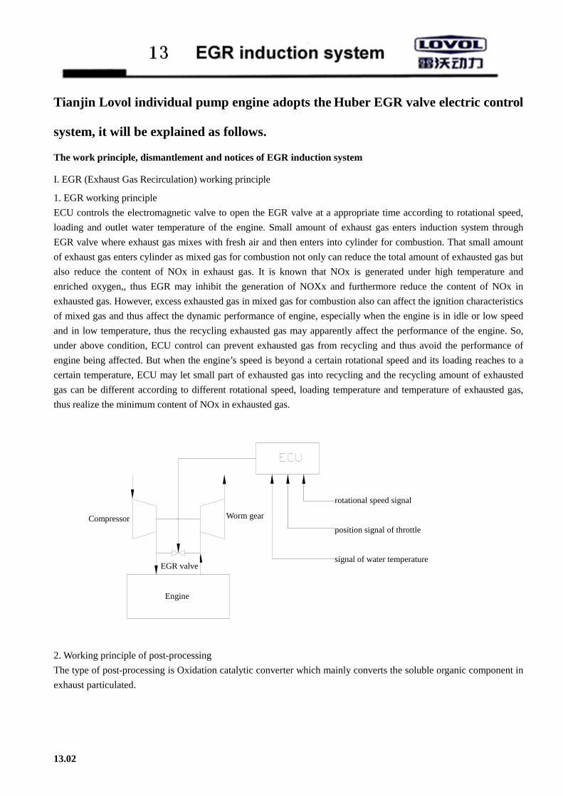
Tianjin Lovol individual pump engine adopts the Huber EGR valve electric control
system, it will be explained as follows.
The work principle, dismantlement and notices of EGR induction system
I. EGR (Exhaust Gas Recirculation) working principle
1. EGR working principle
ECU controls the electromagnetic valve to open the EGR valve at a appropriate time according to rotational speed,
loading and outlet water temperature of the engine. Small amount of exhaust gas enters induction system through
EGR valve where exhaust gas mixes with fresh air and then enters into cylinder for combustion. That small amount
of exhaust gas enters cylinder as mixed gas for combustion not only can reduce the total amount of exhausted gas but
also reduce the content of NOx in exhaust gas. It is known that NOx is generated under high temperature and
enriched oxygen,, thus EGR may inhibit the generation of NOXx and furthermore reduce the content of NOx in
exhausted gas. However, excess exhausted gas in mixed gas for combustion also can affect the ignition characteristics
of mixed gas and thus affect the dynamic performance of engine, especially when the engine is in idle or low speed
and in low temperature, thus the recycling exhausted gas may apparently affect the performance of the engine. So,
under above condition, ECU control can prevent exhausted gas from recycling and thus avoid the performance of
engine being affected. But when the engine’s speed is beyond a certain rotational speed and its loading reaches to a
certain temperature, ECU may let small part of exhausted gas into recycling and the recycling amount of exhausted
gas can be different according to different rotational speed, loading temperature and temperature of exhausted gas,
thus realize the minimum content of NOx in exhausted gas.
发动机
转速信号
油门位置信号
水温信号阀
涡轮压气机
2. Working principle of post-processing
The type of post-processing is Oxidation catalytic converter which mainly converts the soluble organic component in
exhaust particulated.
13.02
Compressor
EGR valve
Worm gear
rotational speed signal
position signal of throttle
signal of water temperature
Engine

3. Schematic diagram of EGR electric units
1 Storage battery
2 Temperature control switch
3 stop electromagnetic valve on fuel injection pump
4 current meter
5 starting motor
6 key switch
7 small generator
8 Relay
9 instrument indicator switch
10 for connecting EGR electromagnetic valve
11 Temperature sensor for cooling water
12 position sensor of throttle
13 power cable
14 water thermometer
15 water temperature sensor
16 oil pressure gauge
17 oil pressure sensor
18 oil pressure alarming light
19 water temperature alarming light
20 This pre-heating system is optional, additional solution may be chosen.
21 12V heating plug
13.03
Technical requirement:
1. Start the main cable of the motor (the thick
line in the diagram), the total resistance can not
be over 0.0034 ohm.
2. The maximum voltage drop in coil circuit of
the starting motor shall not be over 1.0v
3. If the key switch is in its “preheating”
condition, contact points ①—②⑤ are made
connection, contact points ①—②③⑤ are
made connection if it is in “Run” condition, and
contact points ①—②④ are made connection if
it is in “Run” condition, and any contact point is
not connected if it is in “ OFF” condition.
4. Keep the cable as short as possible during
layout.
5. Important suggestions: in order to avoid the
damage of generator:
5.1 Never remove any adaptor if the machine
is not shutdown or the switch is not turn off.
5.2 Ensure the position prior to dismantling or
installing adaptor.
5.3 Never test the current by ignition
5.4 Confirm correct electrode and voltage.
5.5 Never install with arc welding
5.6 The generator can not be run if the storage
battery is not installed or it is not magnetized.

4. ECU Wiring principle diagram
13.04

II Introduction of main elements
3.1 Sensors
Signal of rotational speed: acquire the signal at the W point of the little generator.
(A) Accelerator position sensor
It is mounted an the fuel pump and the signal is acquired at the handle shaft. Its figure and parameters are as follows:
13.05
throttle position sensor
fuel injection pump

(B)Water temperature sensor:
The signal is acquired near the water outlet; Its figure and parameters are as follows:
(C) Position sensor of valve: (see the EGR valve diagram in 13.07).
ECU provides a position signal to EGR valve according to rotational speed, position of throttle and signal of water
temperature, meanwhile, EGR valve send a feedback signal to ECU, then ECU will modify the output signal
according to the feedback signal and finally the feedback signal will basically keep consistent with the output signal.
13.06
water temperature sensor

3.2 ECU:
ECU shall be used in a closure, dry and clean environment.
3.3 Harness
The range of application temperature: -40℃~105℃
3.4 Post-processing system
The DOC shall be cleaned up regularly to prevent excessive carbon accumulation to affect the performance of engine.
3.5 EGR valve:
Technical parameters:
Exhaust gas flow Maximum flow of 180kg/h with △P=50hPa
Air leakage volume with △P=600hPa <0.5 kg/h
Maximum allowable environmental temperature -40 - 150℃
Maximum allowable temperature of actuator 200℃
Range of exhaust gas temperature at exhaust gas inlet 150 - 550℃
Rated current 1.5A
Maximum allowable acceleration axial/radial direction 30g
Mass 0.7kg
Feedback of position signal Available
Position installation (relative to perpendicular line) Within ±85°
Temperature requirements
The inlet temperature at EGR valve shall not be over 550℃, or else the valve may be damaged; and the exhaust gas
temperature shall be above 150℃ to avoid carbon accumulation. For the valve eliminating the carbon deposit
automatically under the temperature of above 300℃, it is recommended that the inlet temperature at valve shall
reach this temperature regularly to eliminate carbon deposit.
Max. allowable temperature of valve parts:
13.07
position sensor 175℃
Driving motor 200℃
transmission box 200℃
valve guiding axle 350℃
mixing chamber 400℃
exhaust inlet 550℃

Notices:
In order to avoid water accumulation in valve inside EGR, the direction of the inlet of the inner valve of valve must
face downward as the lowest point. The valve must be installed within the +/-85o relative to perpendicular direction.
See the figure.
Wrong installation:
EGR valve arrangement diagram:
13.08
heat conduction gasket
Mixture of air and exhaust gas air
exhaust gas
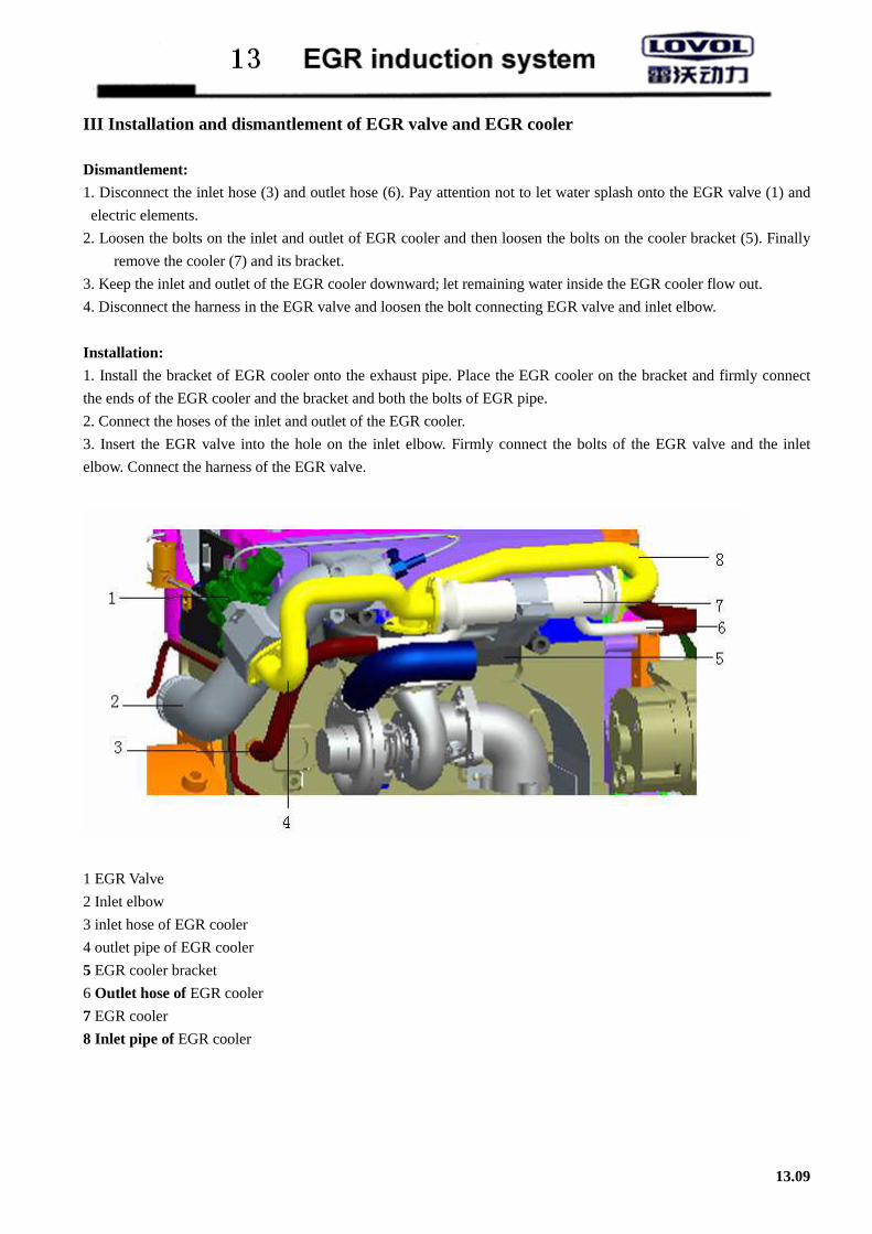
III Installation and dismantlement of EGR valve and EGR cooler
Dismantlement:
1. Disconnect the inlet hose (3) and outlet hose (6). Pay attention not to let water splash onto the EGR valve (1) and
electric elements.
2. Loosen the bolts on the inlet and outlet of EGR cooler and then loosen the bolts on the cooler bracket (5). Finally
remove the cooler (7) and its bracket.
3. Keep the inlet and outlet of the EGR cooler downward; let remaining water inside the EGR cooler flow out.
4. Disconnect the harness in the EGR valve and loosen the bolt connecting EGR valve and inlet elbow.
Installation:
1. Install the bracket of EGR cooler onto the exhaust pipe. Place the EGR cooler on the bracket and firmly connect
the ends of the EGR cooler and the bracket and both the bolts of EGR pipe.
2. Connect the hoses of the inlet and outlet of the EGR cooler.
3. Insert the EGR valve into the hole on the inlet elbow. Firmly connect the bolts of the EGR valve and the inlet
elbow. Connect the harness of the EGR valve.
1 EGR Valve
2 Inlet elbow
3 inlet hose of EGR cooler
4 outlet pipe of EGR cooler
5 EGR cooler bracket
6 Outlet hose of EGR cooler
7 EGR cooler
8 Inlet pipe of EGR cooler
13.09

IV Fault display – fault indicator
Calibration software can recognize various faults in the system. Each fault has its corresponding priority and flash
code. The flash code of the fault of highest priority will be displayed by the fault indicator.
The flash code consists of a sequence of short pulse (0.5 second) and a long pulse (1.5 second). See the following
figure.
The number of short pulse is exactly same with the grade number of priority. The fault with the highest priority is of
the smallest priority grade number. For example, fault caused by excessive current is of the highest priority, but with
smallest grade number of priority. This means that the fault indicator will display two short pulses and then a long
pulse. Meanwhile, any other fault (of the lower priority) will not be displayed by the fault indicator.
Fault grade
(Priority) Fault reason Fault type
2 Excessive current(Electric EGR valve) Self-healing
3 Position sensor of Electric EGR Self-healing
4 TPS position sensor Self-healing
5 Sensor for Water temperature Self-healing
6 Deviation of controller(PID) Without self-healing
9 Fault of electric EGR valve(high zero point) Without self-healing
Some faults may be self-healing but some can not be self-healing. The faults which can not be self-healing have to be
resolved by resetting system, for example, extinction, reignition. Please refer to all the faults listed in the table.
13.10

Address: Jinwei Road, Beichen District, Tianjin
Postcode: 300402
Seal Tel: 0086-022- 26992255 26996802
Service Tel: 0086-022-86995886
FAX: 0086-022-26993784
Homepage: www. lovolengines.com