worldfip technology overview - roma tre university · worldfip technology wf\irw/0101/05-e page 3...
TRANSCRIPT

WorldFIP Technology
WF\IRW/0101/05-E Page 1
HISTORY OF THE DOCUMENT
Name Date Author Type of change
Draft 01 06-20-1996 J.DE AZEVEDO / P.FAURE GEORS Initial versionDraft 02 08-20-1996 J.DE AZEVEDO / P.FAURE GEORS Corrections after re-readings
Version 1 09-16-1996 J.DE AZEVEDO Corrections after re-readingsVersion 4 21/11/1996 J.DE AZEVEDO Definitive documentVersion 5 12/08/1998 N. CRAVOISY Update
Although great care has been taken in drawing up this document, WorldFIP cannot guarantee the exactness of all the information itcontains, and cannot be held responsible for any errors it might contain or any damages that could result from its use.
The presentation, operation and use of the hardware, software and services presented in this document may change at any time, andtheir description in this document cannot be considered binding.

WorldFIP Technology
WF\IRW/0101/05-E Page 2

WorldFIP Technology
WF\IRW/0101/05-E Page 3
PREFACE
This document provides information on all the hardware and software solutions used to equip adevice with a WorldFIP connection.
You can thus use it to evaluate the effort needed to develop a product, and to choose thecomponents, software and tools best suited to your communications needs from among all thoseavailable.
All the hardware and software solutions described in this document are distributed by :
BP30392143 CLAMART CEDEXFRANCE
Tél : (33) (0)1.46.29.17.80Fax : (33) (0)1.46.29.17.85e-mail : [email protected] : http//www.worlfip.org

WorldFIP Technology
WF\IRW/0101/05-E Page 4
CONTENTS
1 INTRODUCTION 6
1.1 WORLDFIP SPECIFICATIONS 61.2 DEFINITION OF A WORLDFIP DEVICE 7
2 WORLDFIP COMPONENTS 8
2.1 COMMUNICATIONS CONTROLLERS 82.1.1 FULLFIP2 82.1.2 MICROFIP 122.1.3 SUMMARY OF COMMUNICATIONS CONTROLLERS 132.2 LINE TOOLS 152.2.1 FIELDRIVE 152.2.2 CREOL (MTC-3055) 162.2.3 OPERA FIPOPTIC2-TS 172.2.4 SUMMARY OF LINE TOOLS 17
3 COMMUNICATIONS LIBRARIES 19
3.1 FIP DEVICE MANAGER 193.1.1 CHARACTERISTICS 193.1.2 DISTRIBUTION 193.2 FIPIULIB 203.2.1 CHARACTERISTICS : 203.2.2 DISTRIBUTION 203.3 MICROFIP HANDLER 203.3.1 CHARACTERISTICS 203.3.2 DISTRIBUTION 203.4 MICRO-MMS 213.4.1 CHARACTERISTICS 213.4.2 DISTRIBUTION 213.5 SUMMARY OF WORLDFIP COMMUNICATIONS LIBRARIES 21
4 DEVELOPMENT TOOLS 22
4.1 OLGA 224.1.1 CHARACTERISTICS 224.1.2 DISTRIBUTION 224.2 FIPACCESS 224.2.1 CHARACTERISTICS 224.2.2 DISTRIBUTION 22

WorldFIP Technology
WF\IRW/0101/05-E Page 5
4.3 THE OBSERVERS 234.3.1 FIPANALYSER 234.3.2 FIPSPY 234.3.3 FIP WATCHER 234.3.4 SUMMARY OF WORLDFIP OBSERVERS 24
5 WORLDFIP PRODUCTS AND SERVICES 25
WorldFIP Technology
WF\IRW/0101/05-E Page 6
1 INTRODUCTION
1.1 WorldFIP Specifications
The WorldFIP protocol is completely specified and is part of European fieldbus standard EN50170.
This standard can be obtained from:• l’UTE ( Union Technique de l’Electricité - 33, Av du Générale Leclerc - BP 23 - 92262 Fontenay
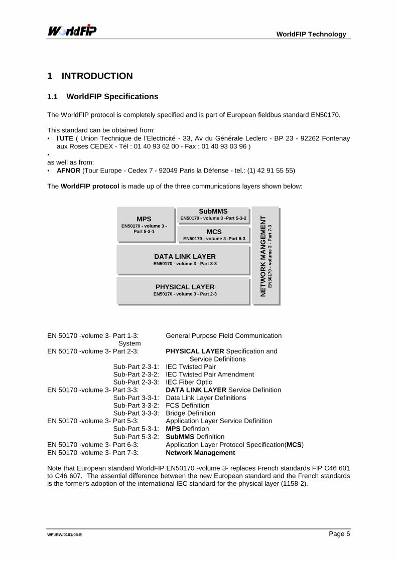
aux Roses CEDEX - Tél : 01 40 93 62 00 - Fax : 01 40 93 03 96 )• as well as from:• AFNOR (Tour Europe - Cedex 7 - 92049 Paris la Défense - tel.: (1) 42 91 55 55) The WorldFIP protocol is made up of the three communications layers shown below:
MPSEN50170 - volume 3 -
Part 5-3-1
SubMMSEN50170 - volume 3 -Part 5-3-2
DATA LINK LAYEREN50170 - volume 3 - Part 3-3
PHYSICAL LAYEREN50170 - volume 3 - Part 2-3 N
ET
WO
RK
MA
NG
EM
EN
TE
N50
170
- vol
ume
3 - P
art 7
-3
MCSEN50170 - volume 3 -Part 6-3
EN 50170 -volume 3- Part 1-3: General Purpose Field Communication
System EN 50170 -volume 3- Part 2-3: PHYSICAL LAYER Specification and Service Definitions Sub-Part 2-3-1: IEC Twisted Pair Sub-Part 2-3-2: IEC Twisted Pair Amendment Sub-Part 2-3-3: IEC Fiber Optic EN 50170 -volume 3- Part 3-3: DATA LINK LAYER Service Definition Sub-Part 3-3-1: Data Link Layer Definitions Sub-Part 3-3-2: FCS Definition Sub-Part 3-3-3: Bridge Definition EN 50170 -volume 3- Part 5-3: Application Layer Service Definition Sub-Part 5-3-1: MPS Defintion Sub-Part 5-3-2: SubMMS Definition EN 50170 -volume 3- Part 6-3: Application Layer Protocol Specification(MCS) EN 50170 -volume 3- Part 7-3: Network Management Note that European standard WorldFIP EN50170 -volume 3- replaces French standards FIP C46 601to C46 607. The essential difference between the new European standard and the French standardsis the former's adoption of the international IEC standard for the physical layer (1158-2).
WorldFIP Technology
WF\IRW/0101/05-E Page 7
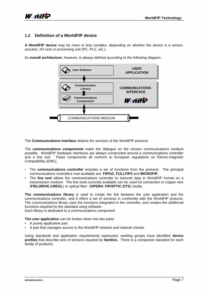
1.2 Definition of a WorldFIP device A WorldFIP device may be more or less complex, depending on whether the device is a sensor,actuator, I/O rack or processing unit (PC, PLC, etc.). Its overall architecture, however, is always defined according to the following diagram:
COMMUNICATIONS MEDIUM
USERAPPLICATION
CommunicationsComponents
CommunicationLibrary COMMUNICATIONS
INTERFACE
User Software
The Communications Interface obtains the services of the WorldFIP protocol. The communications components make the dialogue on the chosen communications mediumpossible. WorldFIP hardware interfaces are always constructed around a communications controllerand a line tool. These components all conform to European regulations on Electro-magneticCompatibility (EMC).
• The communications controller includes a set of functions from the protocol. The principal
communications controllers now available are: FIPIU2, FULLFIP2 and MICROFIP.• The line tool allows the communications controller to transmit data in WorldFIP format on a
transmission medium. The line tools currently available can be used for connection to copper wire(FIELDRIVE,CREOL) or optical fiber (OPERA- FIPOPTIC 2/TS) media.
The communications library is used to create the link between the user application and thecommunications controller, and it offers a set of services in conformity with the WorldFIP protocol.The communications library uses the functions integrated in the controller, and creates the additionalfunctions required by the standard using software. Each library is dedicated to a communications component. The user application can be broken down into two parts:• A purely applicative part• A part that manages access to the WorldFIP network and network checks. Using standards and application requirements expressed, working groups have identified deviceprofiles that describe sets of services required by families. There is a companion standard for eachfamily of products.

WorldFIP Technology
WF\IRW/0101/05-E Page 8
2 WorldFIP COMPONENTS The WorldFIP hardware interface is made up of two complementary components: thecommunications controller and line tools. In order to best fulfill various requirements, a number of different solutions are provided for thecommunications controller. The choice of these components, which manage the protocol, depends on a number of parameterssuch as:• Services available with the controller (bus arbitrator, periodic variables, variable transfer, message
services, requests to bus arbitrator, etc.• Line tools and transformers associated with each controller and their functions.• Technical parameters such as temperatures supported, size, resource consumption, ease of
implementation, transmission speed, etc.• Associated development tools.• Cost requirements for the WorldFIP connection.
2.1 Communications controllers The development of specific communications circuits that include a large part of the protocol hasguaranteed communications interoperability. In addition, since management of the WorldFIP protocolis provided by the components, the power of the microprocessor controlling the communicationscircuit is of no importance to communications performance. The first communications controller (FIP001) was created in 1987. This very simple component, aFIP communication UART, made it possible to validate the physical layer during a pilot application atthe REVIN hydroelectric plant. The first generation of components (FIPART, FULLFIP, FIPIU) was then created. Thesecomponents, which are no longer available, were in conformity with the FIP physical layer (NF C 46-604). They have been replaced by a second generation of components that conform to the EN50170physical layer. These components are: FULLFIP2, FIPIU2 and MICROFIP. In order to ensure compatibility with FIP devices already installed, and to guarantee durability, thenew generation of components includes FIP and EN50170 physical layers. The appropriate physicallayer is selected simply by setting a parameter. The communications components described in this document are all in conformity with the EN50170physical layer and with the FIP physical layer (NF C 46-604). The communications controllers include protocol mechanisms. Each component proposes a list ofservices organized in three categories:• Services related to the bus arbitrator function• Services related to the station function• Network management services The FIPIU2 and FULLFIP2 components make it possible to use all these services. They aredesigned for advanced equipment capable of leading the network (bus arbitrating) and using thevarious possibilities of exchanges provided by the protocol to manipulate from small to very largeamounts of information. MICROFIP provides only some of these services. However, it does include application services suchas input/output peripheral units. It is designed mostly for simple devices that require a high level ofintegration.
2.1.1 FULLFIP2

WorldFIP Technology
WF\IRW/0101/05-E Page 9
FULLFIP2 provides a data link layer and an MPS application layer interface. This component cancarry out the functions of a station (producer/consumer) and a bus arbitrator simultaneously.
2.1.1.1 Services Physical layer services:• choice between EN50170 standard and FIP Data link layer services:• Variable transfer services• Variable updating requests services• Message transfer servicesMPS application layer services• Management of refreshment and promptness statuses• Verification of variable type and size Network management services• Management of medium redundancy if FULLFIP2 is linked to its FIELDUAL peripheral unit.• Management of error counters and performance on both media. Additional functions• Synchronization with specialized interruption• Distribution of precise time
2.1.1.2 Architecture
MicroProcesseur ROM RAM E/S
RAMprivée
FULLFIP2
FIELDRIVE
FIELDTR
Bus Système
Ext
Ck
R/Wn
MA[0]BUSYEOCDTACKnIRQnVSSUA[2]UA[1]UA[0]VSSUDAT[7]UDAT[6]UDAT[5]UDAT[4]UDAT[3]UDAT[2]UDAT[1]UDAT[0]DSnCSn
MA
[1]
ALE
Rdn
Wrn
RE
SE
TnE
MA
nR
Tsk
MA
[8]
MA
[7]
MA
[6]
VS
STS
TCK
TSTn
[2]
VD
DV
DD
TSTn
[1]
TSTn
[0]
MA
[5]
MA
[4]
MA
[3]
MA
[2]
PA
D[4
]P
AD
[3]
PA
D[2
]P
AD
[1]
PA
D[0
]Tx
En1
TxD
TxE
n2R
TSC
TSTx
Er1
TxE
r2V
DD
TxC
kV
DD
CK
inM
Ck
VS
SR
xDC
Dn
PA[19]PA[18]PA[17]PA[16]
PAD[15]PAD[14]PAD[13]PAD[12]PAD[11]PAD[10]
PAD[9]VDDVDD
PAD[8]VSSVSS
BRqnBGtn
PAD[7]PAD[6]
VLSI9348BS 453562VY06482-2FULLFIP2WORLDFIP
PAD[5]
WorldFIP Bus
The private memory of the component (16-bit words) contains: - the buffers of produced and consumed variables - queues of messages waiting for reception or transmission - bus arbitrator tables (if any) - the FIPCODE microcode The FIPCODE microcode used by FULLFIP2 can be loaded in the FULLFIP2 private memory by themicroprocessor or it can be stored in the ROM of the communications component's private bus.

WorldFIP Technology
WF\IRW/0101/05-E Page 10
FULLFIP2 can manage medium redundancywhen associated with FIELDUAL. FIELDUAL provides the following functions: • automatic selection of the receiving
channel• inhibition of one of the two channels upon
transmission• memorization of communications errors on
both channels• indication of the receiving channel• internal looping for tests
WorldFIP Bus 2
A0A1
WDMnD0D1D2D3D4D5
CDnn.c.
PA
D0
TEN
1C
SV
MR
DV
Mn
GN
DG
ND
CLK
2TX
ER
2W
D2n
CD
2nR
AZ2
n
RD
nW
Rn
CS
nR
ES
ETn
CLK
1V
DD
VD
DC
D1n
WD
1nTX
ER
1R
AZ1
n
n.c.Q0Q1SCD1SCD2CLR1CLR2VALTEN1VALTEN2WDGnTEST
FIELDUAL
MHSMCSL-2KFBV-9
MicroProcesseur ROM RAM E/S
RAMprivée FULLFIP2
FIELDRIVE
FIELDTR
Bus Système
FIELDRIVE
FIELDTR
FIELDUAL
WorldFIP Bus 1
FULLFIP2 is compatible with all INTEL and MOTOROLA microprocessor architecture .
2.1.1.3 FIPIU2 FIPIU2 offers a data link layer interface and mechanisms that are useful for the MPS applicationlayer. This component can simultaneously perform station (producer/consumer) and bus arbitratorfunctions.
2.1.1.4 Services Physical layer services:• choice between the EN50170 standard and FIP Data link layer services:• Variable transfer services• Variable updating requests services (free and specified)• Message transfer services Network management services• Indication of errors• Management of performance counters Additional functions• Dating of variable reception for calculating promptness status• Real time clock• Watchdog for application microprocessor• Vectored interrupt checker• Serial acquisition of station address• Input/output ports dedicated to LEDS management

WorldFIP Technology
WF\IRW/0101/05-E Page 11
2.1.1.5 Architecture
ARAM[04]ARAM[05]ARAM[06]ARAM[07]VDDVSSARAM[08]ARAM[09]ARAM[10]ARAM[11]ARAM[12]ARAM[13]ARAM[14]ARAM[15]VDDVSSARAM[16]ARAM[17]ARAM[18]ARAM[19]
ARAM[03
ARAM[02
ARAM[01
ARAM[00
VDD
VSS
WRBUSn
RDBUSn
DRAM[07
DRAM[06
VSS
DRAM[05
DRAM[04
DRAM[03
DRAM[02
DRAM[01
DRAM[00
VDD
VSS
CK2FR
TXD
RTS
RXD
CD
CONSEM
ERRPHYn
SWIN
SWCLK
SWLDn
TEST
ADM[00]ADM[01]ADM[02]ADM[03]VDDVSSADM[04]ADM[05]ADM[06]ADM[07]ADM[08]ADM[09]ADM[10]ADM[11]VDDVSSADM[12]ADM[13]ADM[14]ADM[15]
CSFIP2n
ASKBUS2n
WRMIC2n
RDMIC2n
RDYMIC2n
OEMIC2n
IT1_2
CSFIP1n
ASKBUS1n
WRMIC1n
RDMIC1n
RDYMIC1n
VDD
CLKTR
CLKF
PRGCLKF
INTR
INTAn
ALE
VSS
BHEn
AM[19]
AM[18]
AM[17]
AM[16]
VDD
LED1
LED2
LEDRUN
RESETn
VLSI9345AS 458613VY27059 -WorldFIP1SP1037 IE=01
MicroProcessor ROM I/O
FIPIU2
CREOL
TransfoFIP 1FC1007
RAM
Mono-Processor Architecture

WorldFIP Technology
WF\IRW/0101/05-E Page 12
Two types of architectures can be created using this component: monoprocessor architectures anddual processor architectures. Monoprocessor architecture When FIPIU2 is used in this type of architecture the single microprocessor handles both theapplication layer of the protocol and the user application. The RAM contains the communications objects: buffers, message queues, bus arbitrating tables (ifany) and the application variables. This 8-bit memory is shared between the microprocessor and theFIPIU2 component. Dual processor architecture The FIPIU component can be used in a dualprocessor architecture. With this type ofarchitecture a part of WorldFIPcommunication can be integrated in theexisting architecture. One microprocessor handles thecommunications protocol, whose code islocated in the associated ROM. The othermicroprocessor handles the user applicationand thus has its own ROM. The RAM connected to FIPIU2 is shared byboth microprocessors and FIPIU2 itself.
MicroProcessor1
ROM
FIPIU2
CREOL
TransfoFIP1FC1007
RAM
MicroProcessor2
I/O
ROM
RAM
Existing architecture
Optionnal
FIPIU2 is compatible with all INTEL and MOTOROLA microprocessor architecture .
2.1.2 MICROFIP MICROFIP provides a data link and MPS application layer interface. This component is designedfor devices that are not required to perform the bus arbitrator function and that do not have a largevolume of communication. It provides the station function (producer/consumer).
2.1.2.1 Services
Physical layer services:• choice between the EN50170 standard and FIP. Data link layer services:• Variable transfer services• Message transfer services Network management services• MICROFIP includes management of medium redundancy Additional functions• Input/output ports• Acquisition of station address through a parallel port•

WorldFIP Technology
WF\IRW/0101/05-E Page 13
2.1.2.2 Architecture
WorldFIP Bus 2
EntréesSortiesMICROFIP
FIELDTR ou TransfoFC1007
Optionnel
OptionnelFIELDTR ou TransfoFC1007
FIELDRIVEou CREOL
FIELDRIVE ou CREOL
WorldFIP Bus 1
EntréesSorties
MICROFIP
FIELDTR ou TransfoFC1007
Optionnel
OptionnelFIELDTR ou TransfoFC1007
FIELDRIVEou CREOL
FIELDRIVE ou CREOL
WorldFIP Bus 1
MicroContrôleur
ROMoptionnelle
RAMoptionnelle
Bus Système
RAM 248 octets
Stand-Alone Mode Micro-Controlled Mode
AD[0]AD[1]AD[2]AD[3]AD[4]AD[5]AD[6]AD[7]
A[0]VDDVSSA[1]A[2]A[3]A[4]A[5]A[6]A[7]A[8]
CSN
SU
BS
[7]
SU
BS
[6]
SU
BS
[5]
SU
BS
[4]
SU
BS
[3]
SU
BS
[2]
SU
BS
[1]
SU
BS
[0]
CP
IAIN
VA
PIA
[7]
PIA
[6]
PIA
[5]
VS
SV
DD
VS
SV
DD
PIA
[4]
PIA
[3]
PIA
[2]
PIA
[1]
PIA
[0]
RTS
CTS
RX
A1X
TXD
TXC
KTX
E1
TER
1XW
TC1X
RXD1RST1NRXA2XTXE2TER2XWTC2XRXD2RST2NPIB[7]VSSVDDVSSPIB[6]PIB[5]PIB[4]PIB[3]PIB[2]PIB[1]PIB[0]INVB
EO
RD
nR
WN
ALE
IRQ
0NE
XS
L2E
XS
L1R
ES
1R
ES
2R
ES
3V
SS
VD
DD
EFS
UP
CK
0C
LK XT1
SLO
NE
SE
LDE
MR
STI
NE
XS
L0V
SS
VD
0S
CA
MO
DTS
T[0]
TST[
1]TS
T[2]
SE
LAC
TM
OD
[0]
VD
DM
OD
[1]
CP
IB
VLSI9xxx B72215.U2VY27190MICROFIP
MICROFIP can operate autonomously or under the control of a standard micro-controller. When MICROFIP is in the micro-controlled mode , MICROFIP is compatible with all INTEL andMOTOROLA microprocessor architecture . When operating with a voltage of 5 volts or 3.3 volts, the device satisfies intrinsic securityrequirements for explosive atmospheres.
2.1.3 Summary of communications controllers
2.1.3.1 Electrical Characteristics
FULLFIP2
FIPIU2
MICROFIP
FIELDUAL
Communica-tionsspeeds supported
31.25 kbps 1 Mbps 2.5 Mbps
31.25 kbps 1 Mbps 2.5 Mbps
(31.25 kbps) consult us 1 Mbps (2.5 Mbps) consult us
31.25 kbps 1 Mbps 2.5 Mbps
Packaging
84 PLCC 100MQFP
PLCC44
100PQFP
100MQFP
Operatingtemperature
-40°C / +85°C
-40°C / +85°C
-40°C / +93°C
-40°C / +85°C
Technology
0.8 µCMOS
0.8 µCMOS
0.6 µCMOS
0.6 µCMOS
Input / output
TTL Compatible
C-MOS level
TTL Compatible
C-MOS level

WorldFIP Technology
WF\IRW/0101/05-E Page 14
Power supplyvoltage
5V +/- 10%
5V +/- 10%
5V +/- 10%
5 V +/- 10% 3,3V +/- 10% (Intrinsic security)
Clock
31.25 Kbps: 40MHz 1 Mbps: 64MHz 2.5 Mbps: 80MHz
31.25 Kbps: 20MHz 1 Mbps: 32MHz 2.5 Mbps: 40MHz
31.25 Kbps: 48 MHz 1 Mbps: 48 MHz 2.5 Mbps: 60 MHz
31.25 Kbps: 20 MHz or 40MHz 1 Mbps: 20 MHz or 40MHz 2.5 Mbps: 20 MHz or 40MHz
Consumption
31.25 kbps: 25 mA 1 Mbps: 30 mA 2.5 Mbps: 35 mA LowPower Version FULLFIP2LP (with3.3V +/- 10% ) 31.25 kbps: 1.4 mA
typical: 12 mA
typical: 40 mA
31.25 kbps: 2 mA 1 Mbps: 10 mA 2.5 Mbps: 20 mA
2.1.3.2 Functional Characteristics
FULLFIP2
FIPIU2
MICROFIP Mode
Stand-Alone Mode piloté mContrôleur
Number ofvariables
4095 128-bytevariables with 2Mb of RAM
2000 128-bytevariables or 16000 16-bytevariables with 1 Mb of RAM
2
max. 8
Request fortransfer of anaperiodic variable
supported
supported
not supported
not supported
Management ofRefreshmentStatus
integrated
by software
integrated
integrated
Management ofPromptnessStatus
integrated
integrated (variable dating)
integrated
integrated
Number ofmessagetransmissionchannels
8 + 1 aperiodic
2000 with 128 bytes or 16000 with 16byte with 1 Mb of RAM
-
1
Number ofmessagereception queues
1
max.32
- 1
Message size
256 bytes
256 bytes
-
128 bytes (including6 for addresses)
Management ofrouting andbroadcasting
by software
integrated
-
by software
Lsap management
by software
integrated
-
by software
WorldFIP Technology
WF\IRW/0101/05-E Page 15
Manager of dualmedia
FIELDUALcomponent
-
integrated
integrated
Bus Arbitrator
supported
supported
not supported
not supported
2.2 Line tools Line tools cover the part of the physical layer that depends on the communications medium used. WorldFIP has a number of line tools that can be used to manage the various standardized binaryspeeds for shielded twisted pair or fiber optical lines. With the copper line tools FIELDRIVE and CREOL a transformer must be used to provide galvanicinsulation. FIELDRIVE is used with a FIELDTR31.25, FIELDTR1 or FIELDTR2.5 transformer for transmissionspeeds of 31.25 kbps , 1Mbps and 2.5Mbps respectively. CREOL is used with a TRANSFOFIP 1FC1007, 1Mbps.
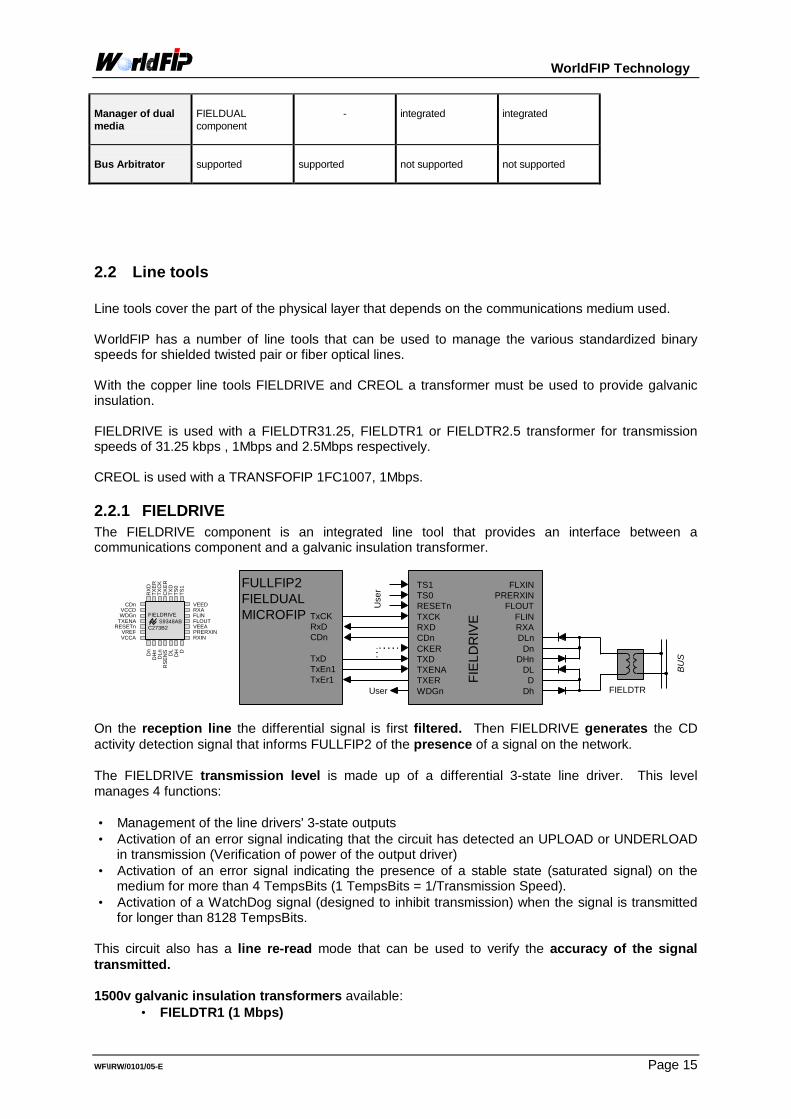
2.2.1 FIELDRIVE The FIELDRIVE component is an integrated line tool that provides an interface between acommunications component and a galvanic insulation transformer.
CDnVCCDWDGn
TXENARESETn
VREFVCCA
Dn
DH
nD
LnR
SE
NS DL
DH D
RX
DTX
ER
TXC
KC
KE
RTX
DTS
0TS
1
VEEDRXAFLINFLOUTVEEAPRERXINRXIN
TS1TS0RESETnTXCKRXDCDnCKERTXDTXENATXERWDGn
TxCKRxDCDn
TxDTxEn1TxEr1
FLXINPRERXIN
FLOUTFLINRXADLn
DnDHn
DLD
Dh
FULLFIP2FIELDUALMICROFIP
User FIELDTR B
US
FIE
LDR
IVE
Use
r
FIELDRIVE S9348ABC273B2
On the reception line the differential signal is first filtered. Then FIELDRIVE generates the CDactivity detection signal that informs FULLFIP2 of the presence of a signal on the network. The FIELDRIVE transmission level is made up of a differential 3-state line driver. This levelmanages 4 functions: • Management of the line drivers' 3-state outputs• Activation of an error signal indicating that the circuit has detected an UPLOAD or UNDERLOAD
in transmission (Verification of power of the output driver)• Activation of an error signal indicating the presence of a stable state (saturated signal) on the
medium for more than 4 TempsBits (1 TempsBits = 1/Transmission Speed).• Activation of a WatchDog signal (designed to inhibit transmission) when the signal is transmitted
for longer than 8128 TempsBits. This circuit also has a line re-read mode that can be used to verify the accuracy of the signaltransmitted. 1500v galvanic insulation transformers available:
• FIELDTR1 (1 Mbps)

WorldFIP Technology
WF\IRW/0101/05-E Page 16
• FIELDTR2.5 (2.5 Mbps)• FIELDTR31.25 (31.25 kbps).
2.2.2 CREOL (MTC-3055) The CREOL component is an integrated line tool that provides an interface between acommunications controller and a galvanic insulation transformer. This component is also known asthe MTC-3055 (Alcatel Mietec).
TRANSFO1FC 1007
BUS
CB
BHBL
INBGND1
VDDRTSTXD
CONSEM
TPCAAHALINAGND2RXDCD0CK2FRERPHYn
ET
2840
9408
TE1SP1015IE=03
RTSTXDCONSEMERPHYnCK2FRCD0RXD
RTSTXD
CONSEMERPHYn
CK2FRCD0RXD
AHA
AL
BHB
BL
FIPIU2
MICROFIPCREOL
detection signal that informs FIPIU2 of the presence of a signal on the network. The CREOL transmission level is made up of a differential 3-state line driver. This level managesthe following functions: • Management of the line drivers' 3-state outputs• Activation of an error signal indicating that the circuit has detected an UPLOAD or UNDERLOAD
in transmission. (Verification of power of the output driver.)• Activation of an error signal indicating that the clock signal is defective.
1500v galvanic insulation transformer available:
• TRANSFOFIP 1FC1007 (1 Mbps).

WorldFIP Technology
WF\IRW/0101/05-E Page 17
2.2.3 OPERA FIPOPTIC2-TS This line tool is a component used to transmit and receive frames in the WorldFIP format on plastic(TP) or silicon (TS) fiber optic transmission media. This component was developed by SAGEM using LFAST II technology.
FIPOPTIC-TS Signals
• Wavelength: : 850 nm (Typ.)• Fibers used: : 50/125 - core diam. 50mm -
: 62.5/125 - core diam. 62.5mm -• Power transmitted fiber 50/125(FO.OUT): : -16dBm(Min.) and –13 dBm
(Max)• Power transmitted fiber 62.5/125(FO.OUT) : -13dBm(Min.) and –10 dBm (Max)• Reception dynamic (FO.IN): : -31dBm(Min) and-11dBm(Max.)• Optical budget of link - fiber 50/125 - : -9 dB• Optical budget of link - fiber 62.5/125 - : -9 dB
On the reception line the optical signal is first converted to an electrical signal, then amplified andfiltered. Then FIPOPTIC generates the CD carrier wave detection signal that informs thecommunications controller of the presence of a signal on the network. The FIPOPTIC transmission level includes a processing and transmission verification level. It isused for: ? Management of the optical output ? Activation of a WatchDog signal when the signal is transmitted for longer than 4 ms +/- 20%
2.2.4 Summary of line tools
2.2.4.1 Electrical Characteristics
CREOL
FIELDRIVE
OPERA FIPOPTIC2/TS
Communication speedssupported
(31.25 kbps) consult us 1 Mbps (2.5 Mbps) consult us
31.25 kbps 1 Mbps 2.5 Mbps
1 Mbps 2.5 Mps
Packaging
SO 20
PLCC 28
Daughter board
Operating Temperature
0°C / +70 °C
-40°C / +85°C
-25°C / +70°C
Inputs/Outputs
CMOS / analog
TTL / analog
TTL / optic
Voltage of power supply
5V +/- 10%
5V +/- 5%
5V +/- 10%
Consumption
max. 10 mA (1 Mbps Rx Mode) max. 170 mA (1 Mbps Tx mode)
max. 40 mA (1 Mbps Rx Mode) max. 120 mA (1 Mbps Tx mode)
typical: 180 mA (TP) typical: 230 mA (TC)
WorldFIP Technology
WF\IRW/0101/05-E Page 18
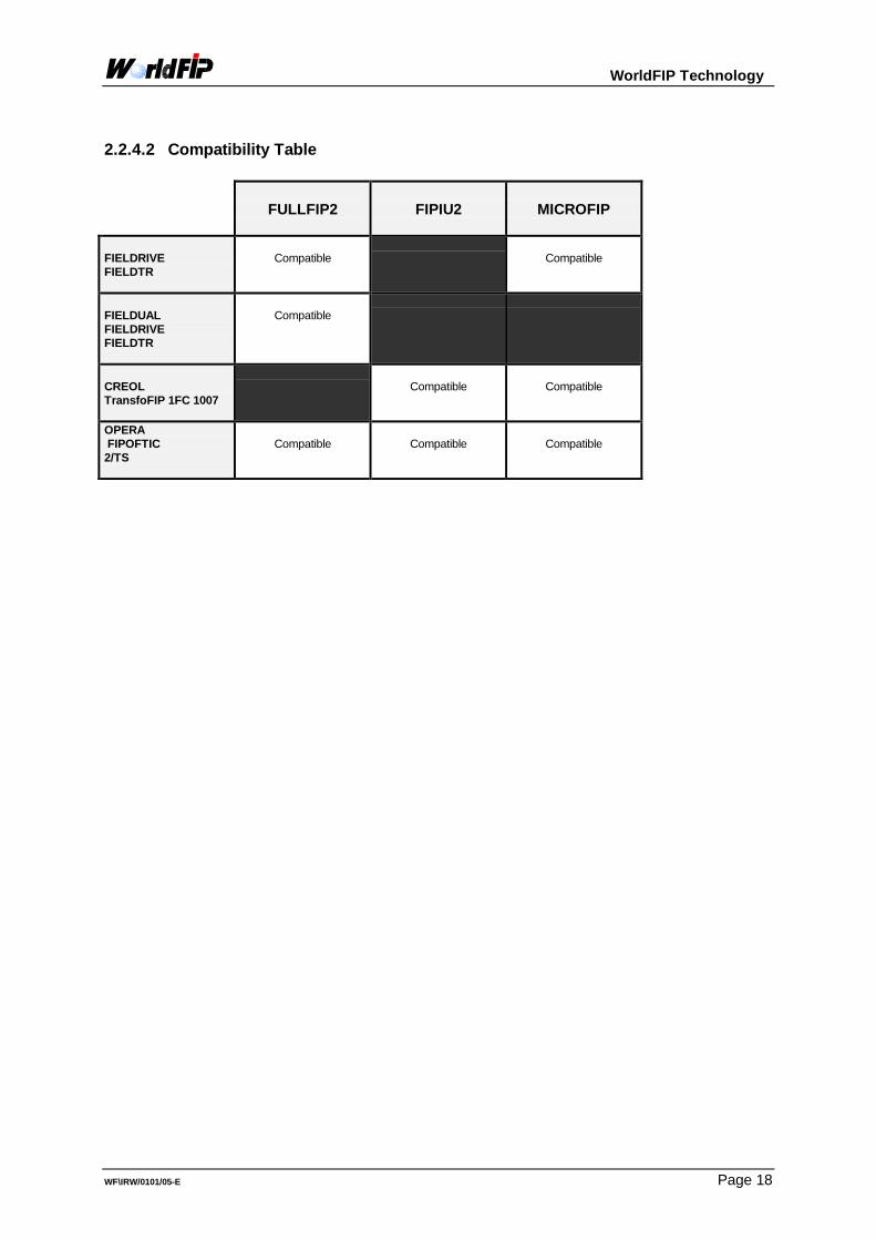
2.2.4.2 Compatibility Table
FULLFIP2
FIPIU2
MICROFIP
FIELDRIVE FIELDTR
Compatible
Compatible
FIELDUAL FIELDRIVE FIELDTR
Compatible
CREOL TransfoFIP 1FC 1007
Compatible
Compatible
OPERA FIPOFTIC 2/TS
Compatible
Compatible
Compatible

WorldFIP Technology
WF\IRW/0101/05-E Page 19
3 COMMUNICATIONS LIBRARIES A communications library is used to create a link between the user application and thecommunications controller. The communications library provides a set of services in conformitywith the WorldFIP protocol. It uses functions integrated in the controller, and with the help ofsoftware performs the additional services required by the standard. Each library is dedicated to a communications component, and there may be several solution fora single component. The criteria for choosing a library will depend first of all on the functionalities required (busarbitrating, periodic variables, aperiodic exchanges, message services, network management, relatedservices, etc.) and secondly on development requirements, whether they be:
• characteristics related to the communications controller.• technical parameters such as code size, ease in implementing, portability on client targets,
or configuration method.• associated development tools.• connection cost requirements.
3.1 FIP DEVICE MANAGER
3.1.1 Characteristics
FIP DEVICE MANAGER (or FDM) is a communications library developed in C ANSI with a C-language programming interface. FDM manages access to the FULLFIP2 component and includes FIPCODE (FULLFIPMicrocode). Configuration is by program and is dynamic. FDM can be used to manage the communications entity (AE/LE or AESEI) dynamically. FDM can be used to constitute a second image of the configuration and thus switch from oneconfiguration to another instantaneously. Configuration of the bus arbitrator function is by program. FDM includes FIPDIAG, a set of services for self-testing the component's hardware resourcesand the integrity of configuration data. FDM manages medium redundancy and includes an interface for managing severalFULLFIP2 (multi-network). SM-MPS network management is integrated in and managed entirely by FDM.
3.1.2 Distribution
FIP DEVICE MANAGER is distributed in the form of C source or object code and associateddocumentation with the possibility of porting by WorldFIP Association technicians. No porting is necessary with CC120, CC121 and CC122 boards in a PC environment underMS-DOS or Windows.

WorldFIP Technology
WF\IRW/0101/05-E Page 20
3.2 FIPIULIB
3.2.1 Characteristics :
FIPIULIB is a communications library developed in C ANSI with a C language programminginterface. FIPIULIB manages access to the FIPIU2 component and allows re-entrant accesses. FIPIULIB can be used to manage the communications entity (AE/LE or AESEI) dynamically. The device is configured by a configurator (OLGA). An other station configuration can be loaded from a file. The Bus Arbitrator architecture can be also loaded from a file. SM-MPS network management is supplied and can be adapted by the user.
3.2.2 Distribution FIPIULIB and DWFLIB are distributed in the form of C source or object code and associateddocumentation with the possibility of porting by WorldFIP Association technicians. No porting is necessary with TSX FPC10 boards in a PC MS-DOS or Windows environment.
3.3 MICROFIP HANDLER
3.3.1 Characteristics MICROFIP-HANDLER is a communications library developed in C ANSI with a C languageprogramming interface. MICROFIP-HANDLER operates with MICROFIP. Configuration is by program. MICROFIP-HANDLER can be used to develop a WorldFIP device equipped with MICROFIPin pilot mode (with microprocessor). MICROFIP-HANDLER have in option a programming interface identical for all commonservices of the FIPIULIB. This option is also used to work with the OLGA configurator ;
3.3.2 Distribution MICROFIP-HANDLER is distributed in C source with documentation.

WorldFIP Technology
WF\IRW/0101/05-E Page 21
3.4 MICRO-MMS
3.4.1 Characteristics
MICRO-MMS is a sub-set of SUB-MMS: read, write and information report. It is made up of a set of functions in C language and can be client, server or both. MICRO-MMS is based on layer 2 message services.
3.4.2 Distribution MICRO-MMS is provided as an option with FIPIULIB or FIP DEVICE MANAGER (source +documentation).
3.5 Summary of WorldFIP communications libraries
FIP DEVICEMANAGER
FIPIULIB
MICROFIP HANDLER
Version studied 4 2 1 Communica. controller FULLFIP2 FIPIU2 MICROFIP Source code yes yes yes Object code yes yes no Code size 42 to 110 Kb 15 to 35 Kb - Equipment profilespossible
1,2,3,4 (c.f.Interop. Guide)
1,2,3,4 (c.f. Interop. Guide)
1,2,3 (c.f.Interop. Guide)
Possible w/managerdevice
yes yes no
Configur. By program and OLGA (option)
OLGA By program and OLGA (option)
Manage-ment ofmedium redundancy
yes no integrated in thecomponent
SM-MPS agent variablesmanaged by the library
presence, report,identification, presence check
presence, report,identif.,pres. check,segment parameters,remote control, load, check, read
presence, identification
SM-MPS manager Variables managed bythe library
presence check presence check none
Manage-ment of SM-MPS variables nothandled by library
By application software By application software no
AESEI or AE/LE mgmt yes yes no Configura-tion of theBA
dynamic by program(without BA shut-down)
dynamic by OLGA orBAGEN (with BA shut-down)
no bus arbitrator
Micro MMS Option yes yes being developed Application mgmt By appli. software By appli. software By appli. software

WorldFIP Technology
WF\IRW/0101/05-E Page 22
4 DEVELOPMENT TOOLS
4.1 OLGA
4.1.1 Characteristics OLGA is a tool used to generate on a PC under Windows the configuration of a WorldFIPdevice using FIPIULIB. OLGA is used to perform the following operations: • application description of an agent device (physical node, logical nodes, functional blocks,
application interface variables) and semi-automatic translation of the application onWorldFIP and its personalization (choice of services used, periodicities, etc.)
• creation of an agent by generating configuration files, a neutral file and a file that dependson the development system (FIP DEVICE MANAGER,FIPIULIB or MICROFIPHANDLER). The latter file is then used to construct the agent by compiling with theapplication program (written in C language by the developer) and the communicationslibrary (FIP DEVICE MANAGER,FIPIULIB or MICROFIP HANDLER).
• create a manager by generating configuration files that contain all the objects needed tomanage the application (application management objects and network managementobjects).
• manipulation of resources on the network with a PC board (CC121,TSX FPC10 or CC165).• creation of the bus arbitrator.
4.1.2 Distribution OLGA is distributed in object code.
4.2 FIPACCESS
4.2.1 Characteristics FIPACCESS is a tool designed to assist with all the coupling development phases. It is builtaround an FDM library whose services can be accessed through a user-friendly man-machineinterface. It can be used under MS-DOS on a PC with a CC120, CC121 or CC122communications board. FIPACCESS is used to perform the following operations: • description of the WorldFIP application (choice of variables and message service
resources)• creation and start-up of the bus arbitrator• access to information exchanged on the network• hosting of a test application linked to the resident library
4.2.2 Distribution FIPACCESS is distributed in object code.
WorldFIP Technology
WF\IRW/0101/05-E Page 23
4.3 The observers
4.3.1 FIPAnalyser FIPAnalyser is a WorldFIP protocol analyzer that operates in a DOS environment. FIPAnalyser includes a TSX-FPC10 communications board and software. It has three operating modes:• Views of error counters.• Traffic capture with manual or triggered start.• Continuous view of traffic on the network with the possibility of selecting frame types by
using a filter.
4.3.2 FIPSPY FIPSPY is a WorldFIP protocol analyzer that operates in a UNIX-SCO environment with theuser-friendly MOTIF interface. FIPSPY includes a CC12x communications board and software. It is a high-performance tool that can be used to combine advanced filters and triggers. It has many functionality as follows:• Management of several observation sessions• Capture of traffic with application of filters and trigger conditions• Statistics on errors (line) and performance (frame totals, periodicity, load, etc.)• Viewing and filing of observation records• Records can be printed out.
4.3.3 FIP WATCHER
FIPWATCHER is a FIP/ WorldFIP analyzer that operates in Windows environment (Windows3.11 and Windows 95).
FIPWATCHER includes a FIPWATCHER communication board and software.
It has many functionality as follows:• Automatic detection of the frame format (FIP or WorldFIP).• Programmable starting of the acquisition (max depth : 3 frames).• Time and date stamping of the frames.• Interpreting of the frames.• Filtering of the stuffing frames.• Transfer of the captured frames into text format files.• Size of the memory : 32 Ko

WorldFIP Technology
WF\IRW/0101/05-E Page 24
4.3.4 Summary of WorldFIP observers
FIPSPY
FIPAnalyser
FIP WATCHER
Board
CC-120, CC-121 1Mb, 31.25kb
TSX FPC10 1Mb
FIP WATCHER 31.25 kb,1Mb,2.5 Mb
Communic.Medium
non-redundant copper
non-redundant copper
non-redundant copper
Hardwareenviron-ment
P.C. compatible P.C. compatible P.C. compatible
Softwareenviron-ment
SCO-UNIX DOS Windows 3.11 orWindows 95
Version V2.0 V3.3 Interface Graphic Text Graphic Operatingmodes
• Continuous acquisition
with or without triggerand filtering thendisplay/save
• Protocol validation
• Acquisition with or
without trigger (lengthdepends on memoryavailable) thendisplay/save
• Acquisition andcontinuousfiltering/display. Last1600 frames saved.
• Acquisition with or
without trigger (lengthdepends on selectedmemory : max 32 Ko)then display/save
• Acquisition andfiltering/display.
Types oftriggers
• Start and stop trigger
(with filters before, duringand after)
• combinations of bytes
• Trigger• Type of frame +
identifier (first 3 bytesin a frame)
• Programmable
starting of theacquisition (maxdepth : 3 frames)
Types of filters
• Various (see
documentation fordetails)
• Types of frames +
identifier• Msg between 2 LSAPs• Aperiodic traffic• All except padding• FIPWAY Msg• FIPIO
• Various (see
documentation fordetails)
Statistics
• various frame counters• average, etc.
• Number of frames
transmitted / received• Number of errors
WorldFIP Technology
WF\IRW/0101/05-E Page 25
5 WorldFIP products and services To best serve WorldFIP members, the WorldFIP product offering is made up of modules with sets ofproducts and services. Each module is designed to meet user requirements and is made up ofelements from the following list: • Documentation and application schemas.• Communications libraries (FIPLIB, FIPIULIB, FIP DEVICE MANAGER, Fipio Standard Device
Software, MICROFIP HANDLER)• Test software and examples• Configurators (FIPC, OLGA, BAGEN)• Hardware:
• evaluation boards (FULLFIP2, FIPIU2, FIPCO1, MICROFIP)• components (FULLFIP2, FIPIU2, FIPCO1, MICROFIP, CREOL, FIELDRIVE, FIELDUAL,
Line transformers)• connection devices• standard communications board (PC bus ISA, VME, G96, M-Module, PCMCIA)
• Test platforms including:• spy with board• test manager (PC board + access library + configurator)• 3- or 5-link daisy chaining cord or the elements to make one
• Training with practical application• Technical assistance• Development assistance: a company that wishes to do so can entrust to WorldFIP all or part of the
development of a network connection for an industrial device. WorldFIP modules are built around products from members and from WorldFIP. The modulesaddress the needs of professionals including:• manufacturers of agent devices• systems manufacturers• installers/assemblers• users and various types of agents:• A decision-maker responsible for evaluating WorldFIP or choosing tools• A hardware development engineer• A software development engineer
A list of these modules with their descriptions can be obtained from WorldFIP.
The hardware and software products described in this document are distributed by WorldFIP.