worldwide locationscyclo.shi.co.jp/document_v2/z2007e-2.1.pdfworldwide locations u.s.a sumitomo...
TRANSCRIPT
IB Series PK1 TypePlanetary Gear Reducer for Servo MotorRight Angle Type
No.Z2007E-2
IB Series PK1 Typ
e Planetary G
ear Redu
cer for Servo
Mo
tor R
igh
t An
gle Typ
e
Power Transmission & Controls Group
Headquarter ThinkPark Tower, 1-1 Osaki 2-chome, Shinagawa-ku, Tokyo 141-6025, Japan
Specifications, dimensions, and other items are subject to change without prior notice.
No.Z2007E-2.1EA06 Printed 2017.06
Worldwide Locations
U.S.ASumitomo Machinery Corporation of America (SMA)4200 Holland Blvd. Chesapeake, VA 23323, U.S.A.TEL (1)757-485-3355 FAX (1)757-485-7490
CanadaSM Cyclo of Canada, Ltd. (SMC)1453 Cornwall Road, Oakville, Canada ON L6J 7T5TEL (1)905-469-1050 FAX (1)905-469-1055
MexicoSM Cyclo de Mexico, S.A. de C.V. (SMME)Av. Desarrollo 541, Col. Finsa, Guadalupe,Nuevo León, México, CP67132TEL (52)81-8144-5130 FAX (52)81-8144-5130
BrazilSumitomo Industrias Pesadas do Brasil Ltda. (SHIB)Rodovia do Acucar (SP-075) Km 26Itu, Sao Paulo, BrasilTEL (55)11-4886-1000 FAX (55)11-4886-1000
ChileSM-Cyclo de Chile Ltda. (SMCH)San Pablo 3507, Quinta Normal, Santiago, ChileTEL (56)2-892-7000 FAX (56)2-892-7001
ArgentinaSM-Cyclo de Argentina S.A. (SMAR)Ing. Delpini, 2236 Area de Promocion el Triangulo,Partido Malvinas Argentinas Grand Bourg,Buenos Aires, Argentina B1615KGBTEL (54)3327-45-4095 FAX (54)3327-45-4099
GuatemalaSM Cyclo de Guatemala Ensambladora, Ltda. (SMGT)Parque Industrial Unisur, 0 Calle B 19-50 Zona 3,Bodega D-1 Delta Bárcenas en Villa Nueva, GuatemalaTEL (502)6648-0500 FAX (502)6631-9171
ColombiaSM Cyclo Colombia, S.A.S. (SMCO)Carrera 11, No.93A-53, Office 203, Bogotá, Colombia TEL (57)1-3000673
GermanySumitomo (SHI) Cyclo Drive Germany GmbH (SCG)Cyclostraße 92, 85229 Markt Indersdorf, GermanyTEL (49)8136-66-0 FAX (49)8136-5771
AustriaSumitomo (SHI) Cyclo Drive Germany GmbH (SCG)SCG Branch Austria Office Gruentalerstraße 30A, 4020 Linz, AustriaTEL (43)732-330958 FAX (43)732-331978
BelgiumSumitomo (SHI) Cyclo Drive Germany GmbH (SCG)SCG Branch Benelux Office Heikneuterlaan 23, 3010 Kessel-Lo, Leuven, Belgium TEL (32)16-60-83-11 FAX (32)16-60-16-39
FranceSM-Cyclo France SAS (SMFR)8 Avenue Christian Doppler, 77700 Serris, FranceTEL (33)164171717 FAX (33)164171718
ItalySM-Cyclo Italy Srl (SMIT)Via dell' Artigianato 23, 20010 Cornaredo (MI), Italy TEL (39)293-481101 FAX (39)293-481103
SpainSM-Cyclo Iberia, S.L.U. (SMIB)C/Landabarri No. 3, 6゜B, 48940 Leioa, Vizcaya, SpainTEL (34)9448-05389 FAX (34)9448-01550
SwedenSumitomo (SHI) Cyclo Drive Germany GmbHSales O�ce Nordic BRO (SCG)Dagsverkarvägen 14, 19736 BRO, SwedenTEL (46)40220031
United KingdomSM-Cyclo UK Ltd. (SMUK)Unit 29, Bergen Way, Sutton Fields Industrial Estate, Kingston upon Hull, HU7 0YQ, East Yorkshire, United KingdomTEL (44)1482-790340 FAX (44)1482-790321
TurkeySM Cyclo Turkey Güç Aktarım Sis. Tic. Ltd. Sti. (SMTR)Büyükdere Çayırbaşı Cd. Dede Yusuf Sk. No: 11,34453 Sarıyer Istanbul, Turkey TEL (90)216-384-4482 FAX (90)216-384-4482
ChinaSumitomo (SHI) Cyclo Drive China, Ltd. (SCT) 11F, SMEG Plaza, No. 1386 Hongqiao Road,Changning District, Shanghai, China (P.C. 200336)TEL (86)21-3462-7877 FAX (86)21-3462-7922
Hong KongSM-Cyclo of Hong Kong Co., Ltd. (SMHK)Rm 1301, CEO Tower, 77 Wing Hong Street,Cheung Sha Wan, Kowloon, Hong Kong TEL (852)2460-1881 FAX (852)2460-1882
KoreaSumitomo (SHI) Cyclo Drive Korea, Ltd. (SCK)Royal Bldg. 9F Rm. 913, 5 Dangju-Dong, Chongno-Ku, Seoul, Korea 03173TEL (82)2-730-0151 FAX (82)2-730-0156
TaiwanTatung SM-Cyclo Co., Ltd. (TSC)22 Chungshan N. Road 3rd., Sec. Taipei, Taiwan 104, R.O.C.TEL (886)2-2595-7275 FAX (886)2-2595-5594
SingaporeSumitomo (SHI) Cyclo Drive Asia Paci�c Pte. Ltd. (SCA)15 Kwong Min Road, Singapore 628718 TEL (65)6591-7800 FAX (65)6863-4238
PhilippinesSumitomo (SHI) Cyclo Drive Asia Paci�c Pte. Ltd. (SCA)Philippines Branch OfficeB2B Granville Industrial Complex, Carmona, Cavite 4116, PhilippinesTEL (63)2-584-4921 FAX (63)2-584-4922TEL (63)46-430-3591TEL (63)46-682-0580
VietnamSM-Cyclo (Vietnam) Co., Ltd. (SMVN)Factory 2B, Lot K1-2-5, Road No. 2-3-5A,Le Minh Xuan Industrial Park, Binh Chanh Dist.,HCMC, Vietnam TEL (84)8-3766-3709 FAX (84)8-3766-3710
MalaysiaSM-Cyclo (Malaysia) Sdn. Bhd. (SMMA)No.7C, Jalan Anggerik Mokara 31/56, Kota Kemuning,Seksyen 31, 40460 Shah Alam, Selangor Darul Ehsan, Malaysia TEL (60)3-5121-0455 FAX (60)3-5121-0578
IndonesiaPT. SM-Cyclo Indonesia (SMID)Jalan Sungkai Blok F 25 No. 09 K, Delta Silicon III,Lippo Cikarang, Bekasi 17530, IndonesiaTEL (62)21-2961-2100 FAX (62)21-2961-2211
ThailandSM-Cyclo (Thailand) Co., Ltd. (SMTH)195 Empire Tower, Unit 2103-4, 21st Floor, South Sathorn Road, Yannawa, Sathorn, Bangkok 10120, ThailandTEL (66)2670-0998 FAX (66)2670-0999
AustraliaSumitomo (SHI) Hansen Australia Pty. Ltd. (SHAU)181 Power St, Glendenning, NSW 2761, AustraliaTEL (61)2-9208-3000 FAX (61)2-9208-3050
IndiaSumi-Cyclo Drive India Private Limited (SMIN)Survey No. 130, Hissa No. 02, Jeevan Nagar, Off Mumbai-Bangalore Bypass, Tathawade, Pune - 411033, IndiaTEL (91)20-6674-2900 FAX (91)20-6674-2901
JapanSumitomo Heavy Industries, Ltd. (SHI)ThinkPark Tower, 1-1 Osaki 2-chome, Shinagawa-ku, Tokyo 141-6025, Japan TEL (81)3-6737-2511 FAX (81)3-6866-5160
1
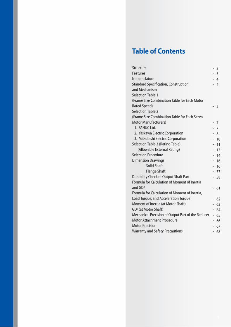
Table of Contents
StructureFeaturesNomenclatureStandard Specification, Construction, and MechanismSelection Table 1(Frame Size Combination Table for Each Motor Rated Speed)Selection Table 2(Frame Size Combination Table for Each Servo Motor Manufacturers)
1. FANUC Ltd.2. Yaskawa Electric Corporation3. Mitsubishi Electric Corporation
Selection Table 3 (Rating Table) (Allowable External Rating)Selection ProcedureDimension Drawings Solid Shaft Flange ShaftDurability Check of Output Shaft PartFormula for Calculation of Moment of Inertia and GD2
Formula for Calculation of Moment of Inertia, Load Torque, and Acceleration TorqueMoment of Inertia (at Motor Shaft)GD2 (at Motor Shaft)Mechanical Precision of Output Part of the ReducerMotor Attachment ProcedureMotor PrecisionWarranty and Safety Precautions
… 2… 3… 4… 4
… 5
… 7… 7… 8… 10… 11… 13… 14… 16… 16… 37… 58
… 61
… 62… 63… 64… 65… 66… 67… 68

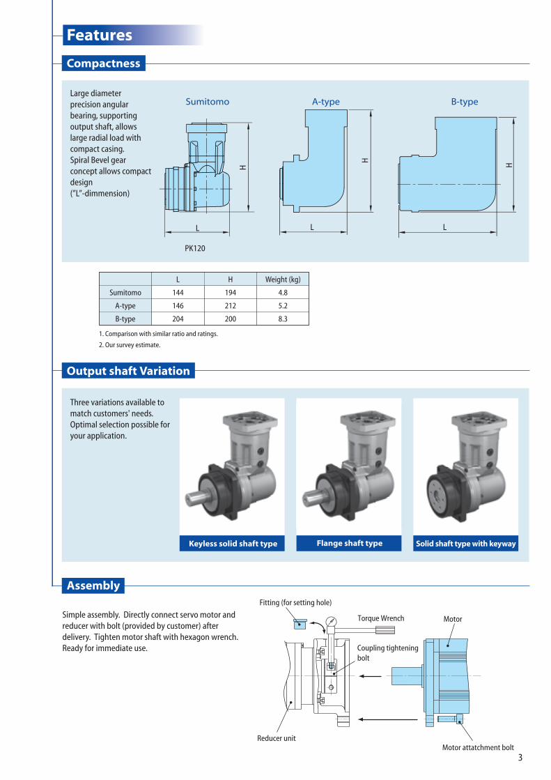
Compactness
Output shaft Variation
Assembly
Motor attatchment bolt
Fitting (for setting hole)
Coupling tighteningbolt
Reducer unit
MotorTorque Wrench
1. Comparison with similar ratio and ratings.
2. Our survey estimate.
Sumitomo
A-type
B-type
L
144
146
204
H
194
212
200
Weight (kg)
4.8
5.2
8.3
Simple assembly. Directly connect servo motor and reducer with bolt (provided by customer) after delivery. Tighten motor shaft with hexagon wrench. Ready for immediate use.
Sun gear of output
Output shaft
Bearing of output(Angular contact ball bearings)
Planetary gear of output
Spiral Bevel Gear
Coupling
Pinion Gear
Number Part Name1 Output Shaft2 Oil Seal3 Bearing of Output4 Sun Gear of Output5 Planetary Gear of Output6 Casing with Internal Gear7 Sun Gear of Input8 Planetary Gear of Input9 Internal Gear of Input
10 Adaptor (Casing)11 Oil Seal12 O-ring13 Bearing14 Casing15 Bearing16 Intermediate Shaft17 Spiral Bevel Gear18 Bevel Pinion Shaft19 Bearing20 Cover (Casing)21 Oil Seal22 Input Shaft Bearing23 Coupling24 Adaptor Plate25 Motor (Provided by Customers)
16
151413121110987654321
17
18
19
20
21
22
24
25
23
Structure Features
Keyless solid shaft type Flange shaft type Solid shaft type with keyway
PK120
Sumitomo A-type B-type
L
H
LL
HH
Large diameter precision angular bearing, supportingoutput shaft, allows large radial load with compact casing.Spiral Bevel gear concept allows compact design (”L”-dimmension)
Three variations available to match customers' needs.Optimal selection possible foryour application.
Fig. 1
2
Compactness
Output shaft Variation
Assembly
Motor attatchment bolt
Fitting (for setting hole)
Coupling tighteningbolt
Reducer unit
MotorTorque Wrench
1. Comparison with similar ratio and ratings.
2. Our survey estimate.
Sumitomo
A-type
B-type
L
144
146
204
H
194
212
200
Weight (kg)
4.8
5.2
8.3
Simple assembly. Directly connect servo motor and reducer with bolt (provided by customer) after delivery. Tighten motor shaft with hexagon wrench. Ready for immediate use.
Sun gear of output
Output shaft
Bearing of output(Angular contact ball bearings)
Planetary gear of output
Spiral Bevel Gear
Coupling
Pinion Gear
Number Part Name1 Output Shaft2 Oil Seal3 Bearing of Output4 Sun Gear of Output5 Planetary Gear of Output6 Casing with Internal Gear7 Sun Gear of Input8 Planetary Gear of Input9 Internal Gear of Input
10 Adaptor (Casing)11 Oil Seal12 O-ring13 Bearing14 Casing15 Bearing16 Intermediate Shaft17 Spiral Bevel Gear18 Bevel Pinion Shaft19 Bearing20 Cover (Casing)21 Oil Seal22 Input Shaft Bearing23 Coupling24 Adaptor Plate25 Motor (Provided by Customers)
16
151413121110987654321
17
18
19
20
21
22
24
25
23
Structure Features
Keyless solid shaft type Flange shaft type Solid shaft type with keyway
PK120
Sumitomo A-type B-type
L
H
LL
HH
Large diameter precision angular bearing, supportingoutput shaft, allows large radial load with compact casing.Spiral Bevel gear concept allows compact design (”L”-dimmension)
Three variations available to match customers' needs.Optimal selection possible foryour application.
Fig. 1
3

4
Nomenclature, Standard Specification
Nomenclature
Standard SpecificationBacklash Initial backlash setting is 6 or 15-minute.
Efficiency 86% or more at rated output torque (with reduction ratio 6, 8, 11, 15, 27)
Noise Level 70dB(A) 0.5m *Varies depending on models and mounting condition.
Lubrication systemGrease lubricationThe unit is filled with grease at the time of shipping. It is ready for immediate use.
Reduction systemPlanetary gear mechanism (2nd-stage) Bevel gear mechanism (1st-stage)Double stage type (Reduction Ratio: 6, 8, 11, 15, 27)Triple stage type (Reduction Ratio: 23, 33, 45, 50, 63, 68, 99, 122, 135, 243)
Output shaft rotation direction
Oposite direction as the rotation direction of input gear.
MaterialCase with internal gear and gear: Chrome-Molybdenum SteelJoint cover, Adapter prate, Adaptor (Casing), Casing, Cover (Casing): Aluminum alloyOutput and input shaft: S45C
Mounting location Indoor (without dust and water)
Ambient temperature0~40°CConsult us when the operation condition exceeds the above and when special grease is necessary such as food manufacturing machine.
Ambient humidity 85% or less. There should be no condensation.
Altitude 1000m or below
Ambient atmosphere There should be no corrosive gases, explosive gases, vapor, or dust.
Mounting angle All angles possible (no limitation)
PaintBlack oxide coating for housing with internal gearOutput shaft comes with rustproof treatment at the time of shipping.
Actual reduction ratio Please refer ratio table above.
Surface temperature of the reducer
80°C or below. Consult us when operating continuously.
IB Series PK1 Type
Ratio
Ratio 6 8 11 15 23 27 33 45 50 63 68 99 122 135 243
Actual reduction ratio 5.5 7.5 11 15 22.5 27 33 45 49.5 63 67.5 99 121.5 135 243
A N F X − PK120 F − 7A LD − 15
MC Drive IB Series
Output Shaft Direction (Unlimited Mounting Direction)
Special
Input Method
Motor Flange Code
Backlash Symbol
6 min specification: LB15 min specification: LD
Reduction RatioType and Frame Size
PK110120130
Output Shaft Type SymbolSolid Shaft (Keyless) N
Solid Shaft (with Key) WFlange Shaft F
Mounting (Flange Attachment Type)
PK1
Type
5
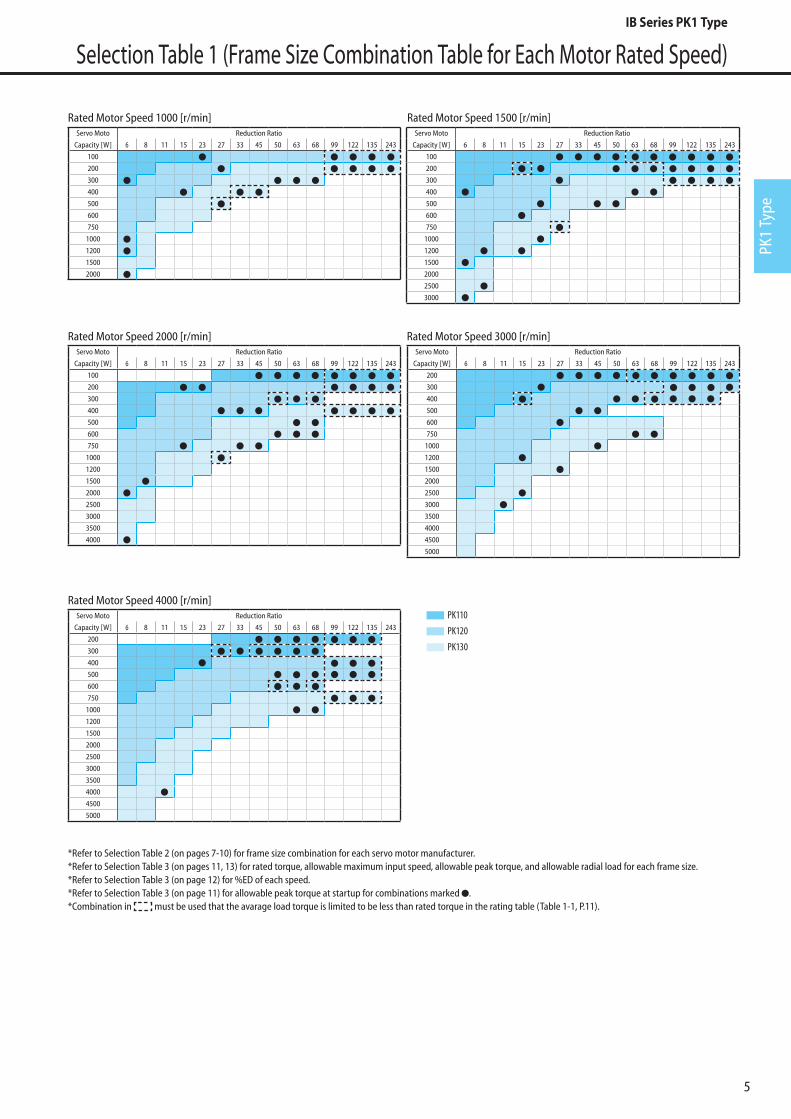
Selection Table 1 (Frame Size Combination Table for Each Motor Rated Speed)
Servo Moto Reduction Ratio
Capacity [W] 6 8 11 15 23 27 33 45 50 63 68 99 122 135 243
100
200
300
400
500
600
750
1000
1200
1500
2000
Servo Moto Reduction Ratio
Capacity [W] 6 8 11 15 23 27 33 45 50 63 68 99 122 135 243
100
200
300
400
500
600
750
1000
1200
1500
2000
2500
3000
3500
4000
Servo Moto Reduction Ratio
Capacity [W] 6 8 11 15 23 27 33 45 50 63 68 99 122 135 243
200
300
400
500
600
750
1000
1200
1500
2000
2500
3000
3500
4000
4500
5000
Servo Moto Reduction Ratio
Capacity [W] 6 8 11 15 23 27 33 45 50 63 68 99 122 135 243
200
300
400
500
600
750
1000
1200
1500
2000
2500
3000
3500
4000
4500
5000
Rated Motor Speed 1000 [r/min]
Rated Motor Speed 2000 [r/min] Rated Motor Speed 3000 [r/min]
Rated Motor Speed 4000 [r/min]
Servo Moto Reduction Ratio
Capacity [W] 6 8 11 15 23 27 33 45 50 63 68 99 122 135 243
100
200
300
400
500
600
750
1000
1200
1500
2000
2500
3000
Rated Motor Speed 1500 [r/min]
*Refer to Selection Table 2 (on pages 7-10) for frame size combination for each servo motor manufacturer.*Refer to Selection Table 3 (on pages 11, 13) for rated torque, allowable maximum input speed, allowable peak torque, and allowable radial load for each frame size.*Refer to Selection Table 3 (on page 12) for %ED of each speed.*Refer to Selection Table 3 (on page 11) for allowable peak torque at startup for combinations marked .*Combination in must be used that the avarage load torque is limited to be less than rated torque in the rating table (Table 1-1, P.11).
PK110
PK120
PK130
IB Series PK1 Type

6
Selection Table 1 (Frame Size Combination Table for Each Motor Rated Speed)
No Load Running Torque [SI Unit]
Frame Size
UnitReduction Ratio
6(5.5)
8(7.5)
11(11)
15(15)
23(22.5)
27(27)
33(33)
45(45)
50(49.5)
63(63)
68(67.5)
99(99)
122(121.5)
135(135)
243(243)
PK110
N·m
0.29 0.27 0.21 0.20 0.27 0.19 0.20 0.20 0.25 0.20 0.25 0.19 0.25 0.19 0.19
PK120 0.42 0.36 0.42 0.39 0.36 0.39 0.39 0.39 0.36 0.39 0.36 0.36 0.36 0.36 0.36
PK130 0.79 0.71 0.68 0.64 0.64 0.64 0.64 0.64 0.61 0.6 0.61 0.61 0.61 0.61 0.61
*Torque necessary at the input side to rotate the reducer at no load condition.*This is the representative value when the ambient temperature is 200C.
IB Series PK1 Type
PK1
Type
7
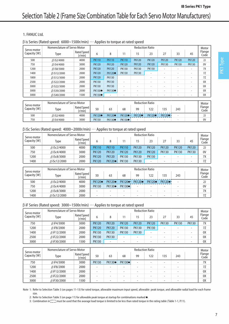
Selection Table 2 (Frame Size Combination Table for Each Servo Motor Manufacturers)
1. FANUC Ltd.
is Series (Rated speed: 6000~1500r/min) … Applies to torque at rated speed
Servo motor Capacity [W]
Nomenclature of Servo Motor Reduction Ratio Motor Flange CodeType Rated Speed
[r/min] 6 8 11 15 23 27 33 45
500 iS2/4000 4000 PK110 PK110 PK110 PK120 PK120 PK120 PK120 PK120 2J750 iS4/4000 3000 PK120 PK120 PK120 PK120 PK120 PK130 PK130 PK130 0V
1200 iS8/3000 2000 PK120 PK120 PK130 PK130 PK130 - - - 7X
1400 iS12/2000 2000 PK120 PK120 PK130 PK130 - - - - 7Z
1800 iS12/3000 2000 PK120 PK130 - - - - 7Z
2500 iS22/2000 2000 PK130 PK130 - - - - - - 0X
3000 iS22/3000 2000 PK130 PK130 - - - - - - 0X
3000 iS30/2000 2000 PK130 PK130 - - - - - - 0X3000 iS40/2000 1500 PK130 - - - - - - - 0X
Servo motor Capacity [W]
Nomenclature of Servo Motor Reduction Ratio Motor Flange CodeType Rated Speed
[r/min] 50 63 68 99 122 135 243
500 iS2/4000 4000 PK120 PK120 PK120 PK120 PK120 PK120 - 2J750 iS4/4000 3000 PK130 PK130 PK130 - - - - 0V
iSc Series (Rated speed: 4000~2000r/min) … Applies to torque at rated speed
Servo motor Capacity [W]
Nomenclature of Servo Motor Reduction Ratio Motor Flange CodeType Rated Speed
[r/min] 6 8 11 15 23 27 33 45
500 iSc2/4000 4000 PK110 PK110 PK110 PK120 PK120 PK120 PK120 PK120 2J750 iSc4/4000 3000 PK120 PK120 PK120 PK120 PK120 PK130 PK130 PK130 0V
1200 iSc8/3000 2000 PK120 PK120 PK130 PK130 PK130 - - - 7X1400 iSc12/2000 2000 PK120 PK120 PK130 PK130 - - - - 7Z
Servo motor Capacity [W]
Nomenclature of Servo Motor Reduction Ratio Motor Flange CodeType Rated Speed
[r/min] 50 63 68 99 122 135 243
500 iSc2/4000 4000 PK120 PK120 PK120 PK120 PK120 PK120 - 2J750 iSc4/4000 3000 PK130 PK130 PK130 - - - - 0V
1200 iSc8/3000 2000 - - - - - - - 7X1400 iSc12/2000 2000 - - - - - - - 7Z
iF Series (Rated speed: 3000~1500r/min) … Applies to torque at rated speed
Servo motor Capacity [W]
Nomenclature of Servo Motor Reduction Ratio Motor Flange CodeType Rated Speed
[r/min] 6 8 11 15 23 27 33 45
750 iF4/3000 3000 PK120 PK120 PK120 PK120 PK120 PK130 PK130 PK130 7X1200 iF8/2000 2000 PK120 PK120 PK130 PK130 PK130 - - - 7Z1400 iF12/2000 2000 PK130 PK130 PK130 PK130 - - - - 0X2500 iF22/2000 2000 PK130 PK130 - - - - - - 0X3000 iF30/2000 1500 PK130 - - - - - - - 0X
Servo motor Capacity [W]
Nomenclature of Servo Motor Reduction Ratio Motor Flange CodeType Rated Speed
[r/min] 50 63 68 99 122 135 243
750 iF4/3000 3000 PK130 PK130 PK130 - - - - 7X1200 iF8/2000 2000 - - - - - - - 7Z1400 iF12/2000 2000 - - - - - - - 0X2500 iF22/2000 2000 - - - - - - - 0X3000 iF30/2000 1500 - - - - - - - 0X
Note 1: Refer to Selection Table 3 (on pages 11-13) for rated torque, allowable maximum input speed, allowable peak torque, and allowable radial load for each frame size.
2: Refer to Selection Table 3 (on page 11) for allowable peak torque at startup for combinations marked . 3: Combination in must be used that the avarage load torque is limited to be less than rated torque in the rating table (Table 1-1, P.11).
IB Series PK1 Type

8
Selection Table 2 (Frame Size Combination Table for Each Servo Motor Manufacturers)
2. Yaskawa Electric Corporation
∑-7 Series SGM7J model (Rated speed: 3000r/min)
Servo motor Capacity [W]
Nomenclature of Servo Motor Reduction Ratio Motor Flange CodeType Rated Speed
[r/min] 6 8 11 15 23 27 33 45
200 SGM7J-02A 3000 PK110 PK110 PK110 PK110 PK110 PK110 PK110 PK110 2R400 SGM7J-04A 3000 PK110 PK110 PK110 PK110 PK120 PK120 PK120 PK120 2R600 SGM7J-06A 3000 PK110 PK120 PK120 PK120 PK120 PK120 PK130 PK130 2R750 SGM7J-08A 3000 PK120 PK120 PK120 PK120 PK120 PK130 PK130 PK130 1G
Servo motor Capacity [W]
Nomenclature of Servo Motor Reduction Ratio Motor Flange CodeType Rated Speed
[r/min] 50 63 68 99 122 135 243
200 SGM7J-02A 3000 PK110 PK110 PK110 PK110 PK110 PK110 PK110 2R400 SGM7J-04A 3000 PK120 PK120 PK120 PK120 PK120 PK120 - 2R600 SGM7J-06A 3000 PK130 PK130 PK130 - - - - 2R750 SGM7J-08A 3000 PK130 PK130 PK130 - - - - 1G
∑-7 Series SGM7A model (Rated speed: 3000r/min)
Servo motor Capacity [W]
Nomenclature of Servo Motor Reduction Ratio Motor Flange CodeType Rated Speed
[r/min] 6 8 11 15 23 27 33 45
200 SGM7A-02A 3000 PK110 PK110 PK110 PK110 PK110 PK110 PK110 PK110 2R400 SGM7A-04A 3000 PK110 PK110 PK110 PK110 PK120 PK120 PK120 PK120 2R600 SGM7A-06A 3000 PK110 PK120 PK120 PK120 PK120 PK120 PK130 PK130 2R750 SGM7A-08A 3000 PK120 PK120 PK120 PK120 PK120 PK130 PK130 PK130 1G
1000 SGM7A-10A 3000 PK120 PK120 PK120 PK120 PK130 PK130 PK130 PK130 1G1500 SGM7A-15A 3000 PK120 PK120 PK130 PK130 PK130 PK130 - - 1L2000 SGM7A-20A 3000 PK120 PK120 PK130 PK130 - - - - 1L2500 SGM7A-25A 3000 PK120 PK130 PK130 PK130 - - - - 1L3000 SGM7A-30A 3000 PK130 PK130 PK130 - - - - - 1T4000 SGM7A-40A 3000 PK130 PK130 - - - - - - 1T5000 SGM7A-50A 3000 PK130 - - - - - - - 1T
Servo motor Capacity [W]
Nomenclature of Servo Motor Reduction Ratio Motor Flange CodeType Rated Speed
[r/min] 50 63 68 99 122 135 243
200 SGM7A-02A 3000 PK110 PK110 PK110 PK110 PK110 PK110 PK110 2R400 SGM7A-04A 3000 PK120 PK120 PK120 PK120 PK120 PK120 - 2R600 SGM7A-06A 3000 PK130 PK130 PK130 - - - - 2R750 SGM7A-08A 3000 PK130 PK130 PK130 - - - - 1G
1000 SGM7A-10A 3000 - - - - - - - 1G1500 SGM7A-15A 3000 - - - - - - - 1L2000 SGM7A-20A 3000 - - - - - - - 1L2500 SGM7A-25A 3000 - - - - - - - 1L3000 SGM7A-30A 3000 - - - - - - - 1T4000 SGM7A-40A 3000 - - - - - - - 1T5000 SGM7A-50A 3000 - - - - - - - 1T
Note 1: Refer to Selection Table 3 (on pages 11-13) for rated torque, allowable maximum input speed, allowable peak torque, and allowable radial load for each frame size.
2: Refer to Selection Table 3 (on page 11) for allowable peak torque at startup for combinations marked . 3: Combination in must be used that the avarage load torque is limited to be less than rated torque in the rating table (Table 1-1, P.11).
IB Series PK1 Type

PK1
Type
9
Selection Table 2 (Frame Size Combination Table for Each Servo Motor Manufacturers)
Yaskawa Electric Corporation
∑-7 Series SGM7P model (Rated speed: 3000r/min)
Servo motor Capacity [W]
Nomenclature of Servo Motor Reduction Ratio Motor Flange CodeType Rated Speed
[r/min] 6 8 11 15 23 27 33 45
200 SGM7P-02A 3000 PK110 PK110 PK110 PK110 PK110 PK110 PK110 PK110 2T400 SGM7P-04A 3000 PK110 PK110 PK110 PK110 PK120 PK120 PK120 PK120 2T750 SGM7P-08A 3000 PK120 PK120 PK120 PK120 PK120 PK130 PK130 PK130 7X
1500 SGM7P-15A 3000 PK120 PK120 PK130 PK130 PK130 PK130 - - 7X
Servo motor Capacity [W]
Nomenclature of Servo Motor Reduction Ratio Motor Flange CodeType Rated Speed
[r/min] 50 63 68 99 122 135 243
200 SGM7P-02A 3000 PK110 PK110 PK110 PK110 PK110 PK110 PK110 2T400 SGM7P-04A 3000 PK120 PK120 PK120 PK120 PK120 PK120 - 2T750 SGM7P-08A 3000 PK130 PK130 PK130 - - - - 7X
1500 SGM7P-15A 3000 - - - - - - - 7X
∑-7 Series SGM7G model (Rated speed: 1500r/min)
Servo motor Capacity [W]
Nomenclature of Servo Motor Reduction Ratio Motor Flange CodeType Rated Speed
[r/min] 6 8 11 15 23 27 33 45
300 SGM7G-03A 1500 PK110 PK110 PK120 PK120 PK120 PK120 PK130 PK130 8E450 SGM7G-05A 1500 PK120 PK120 PK120 PK120 PK120 PK130 PK130 PK130 8E850 SGM7G-09A 1500 PK120 PK120 PK130 PK130 PK130 - - - 7Z
1300 SGM7G-13A 1500 PK120 PK120 PK130 PK130 - - - - 7Z1800 SGM7G-20A 1500 PK130 PK130 - - - - - - 7Z2900 SGM7G-30A 1500 PK130 - - - - - - - 0X
Servo motor Capacity [W]
Nomenclature of Servo Motor Reduction Ratio Motor Flange CodeType Rated Speed
[r/min] 50 63 68 99 122 135 243
300 SGM7G-03A 1500 PK130 PK130 PK130 PK130 PK130 PK130 PK130 8E450 SGM7G-05A 1500 PK130 - - - - - - 8E850 SGM7G-09A 1500 - - - - - - - 7Z
1300 SGM7G-13A 1500 - - - - - - - 7Z1800 SGM7G-20A 1500 - - - - - - - 7Z2900 SGM7G-30A 1500 - - - - - - - 0X
Note 1: Refer to Selection Table 3 (on pages 11-13) for rated torque, allowable maximum input speed, allowable peak torque, and allowable radial load for each frame size.
2: Refer to Selection Table 3 (on page 11) for allowable peak torque at startup for combinations marked . 3: Combination in must be used that the avarage load torque is limited to be less than rated torque in the rating table (Table 1-1, P.11).
IB Series PK1 Type

10
3. Mitsubishi Electric Corporation
MELSERV0-J4 HG-KR Series (Rated speed: 3000r/min)
Servo motor Capacity [W]
Nomenclature of Servo Motor Reduction Ratio Motor Flange CodeType Rated Speed
[r/min] 6 8 11 15 23 27 33 45
200 HG-KR23(B) 3000 PK110 PK110 PK110 PK110 PK110 PK110 PK110 PK110 2R400 HG-KR43(B) 3000 PK110 PK110 PK110 PK110 PK120 PK120 PK120 PK120 2R750 HG-KR73(B) 3000 PK120 PK120 PK120 PK120 PK120 PK130 PK130 PK130 1G
Servo motor Capacity [W]
Nomenclature of Servo Motor Reduction Ratio Motor Flange CodeType Rated Speed
[r/min] 50 63 68 99 122 135 243
200 HG-KR23(B) 3000 PK110 PK110 PK110 PK110 PK110 PK110 PK110 2R400 HG-KR43(B) 3000 PK120 PK120 PK120 PK120 PK120 PK120 - 2R750 HG-KR73(B) 3000 PK130 PK130 PK130 - - - - 1G
MELSERV0-J4 HG-MR Series (Rated speed: 3000r/min)
Servo motor Capacity [W]
Nomenclature of Servo Motor Reduction Ratio Motor Flange CodeType Rated Speed
[r/min] 6 8 11 15 23 27 33 45
200 HG-MR23(B) 3000 PK110 PK110 PK110 PK110 PK110 PK110 PK110 PK110 2R400 HG-MR43(B) 3000 PK110 PK110 PK110 PK110 PK120 PK120 PK120 PK120 2R750 HG-MR73(B) 3000 PK120 PK120 PK120 PK120 PK120 PK130 PK130 PK130 1G
Servo motor Capacity [W]
Nomenclature of Servo Motor Reduction Ratio Motor Flange CodeType Rated Speed
[r/min] 50 63 68 99 122 135 243
200 HG-MR23(B) 3000 PK110 PK110 PK110 PK110 PK110 PK110 PK110 2R400 HG-MR43(B) 3000 PK120 PK120 PK120 PK120 PK120 PK120 - 2R750 HG-MR73(B) 3000 PK130 PK130 PK130 - - - - 1G
MELSERV0-J4 HG-SR Series (Rated speed: 2000r/min)
Servo motor Capacity [W]
Nomenclature of Servo Motor Reduction Ratio Motor Flange CodeType Rated Speed
[r/min] 6 8 11 15 23 27 33 45
500 HG-SR52(B) 2000 PK120 PK120 PK120 PK120 PK120 PK130 PK130 PK130 7Z1000 HG-SR102(B) 2000 PK120 PK120 PK130 PK130 PK130 PK130 - - 7Z1500 HG-SR152(B) 2000 PK120 PK120 PK130 PK130 - - - - 7Z2000 HG-SR202(B) 2000 PK130 PK130 - - - - - - 0X3500 HG-SR352(B) 2000 PK130 - - - - - - - 0X
Servo motor Capacity [W]
Nomenclature of Servo Motor Reduction Ratio Motor Flange CodeType Rated Speed
[r/min] 50 63 68 99 122 135 243
500 HG-SR52(B) 2000 PK130 PK130 PK130 - - - - 7Z1000 HG-SR102(B) 2000 - - - - - - - 7Z1500 HG-SR152(B) 2000 - - - - - - - 7Z2000 HG-SR202(B) 2000 - - - - - - - 0X3500 HG-SR352(B) 2000 - - - - - - - 0X
Note 1: Refer to Selection Table 3 (on pages 11-13) for rated torque, allowable maximum input speed, allowable peak torque, and allowable radial load for each frame size.
2: Refer to Selection Table 3 (on page 11) for allowable peak torque at startup for combinations marked . 3: Combination in must be used that the avarage load torque is limited to be less than rated torque in the rating table (Table 1-1, P.11).
Selection Table 2 (Frame Size Combination Table for Each Servo Motor Manufacturers)IB Series PK1 Type
PK1
Type
11
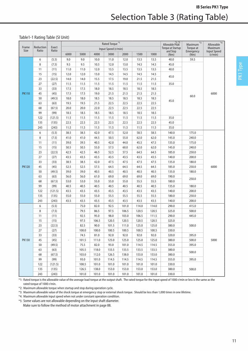
Selection Table 3 (Rating Table)
FrameSize
ReductionRatio
ExactRatio
Rated Torque *1Allowable Peak
Torque at Startup and Stop
(Nm)
MaximumTorque at
Emergency(Nm)
AllowableMaximum
Input Speed(r/min)
Input Speed (r/min)
6000 5000 4000 3000 2000 1500 1000
PK110
6 (5.5) 9.0 9.0 10.0 11.0 12.0 13.5 13.5 40.0 59.5
6000
8 (7.5) 9.5 9.5 10.5 12.0 13.0 14.5 14.5 45.0
60.0
11 (11) 11.0 11.0 12.0 13.5 13.5 13.5 13.5 40.0
15 (15) 12.0 12.0 13.0 14.5 14.5 14.5 14.545.0
23 (22.5) 14.0 14.0 15.5 17.5 19.0 21.5 21.5
27 (27) 11.5 11.5 11.5 11.5 11.5 11.5 11.5 35.0
33 (33) 17.5 17.5 18.0 18.5 18.5 18.5 18.5
45.0
45 (45) 17.5 17.5 19.0 21.5 21.5 21.5 21.5
50 (49.5) 18.0 18.0 18.5 18.5 18.5 18.5 18.5
63 (63) 19.5 19.5 21.5 22.5 22.5 22.5 22.5
68 (67.5) 20.0 20.0 22.0 22.5 22.5 22.5 22.5
99 (99) 18.5 18.5 18.5 18.5 18.5 18.5 18.5
122 (121.5) 11.5 11.5 11.5 11.5 11.5 11.5 11.5 35.0
135 (135) 22.5 22.5 22.5 22.5 22.5 22.5 22.5 45.0
243 (243) 11.5 11.5 11.5 11.5 11.5 11.5 11.5 35.0
PK120
6 (5.5) 38.5 38.5 42.0 47.5 52.0 58.5 58.5 140.0 175.0
6000
8 (7.5) 41.0 41.0 44.5 50.5 55.0 62.0 62.0 145.0 240.0
11 (11) 39.0 39.5 40.5 42.0 44.0 45.5 47.5 135.0 175.0
15 (15) 50.5 50.5 55.0 57.5 60.0 62.0 62.0 145.0 240.0
23 (22.5) 42.5 42.5 46.5 52.5 57.5 64.5 64.5 185.0 250.0
27 (27) 43.5 43.5 43.5 43.5 43.5 43.5 43.5 140.0 200.0
33 (33) 38.5 38.5 42.0 47.5 47.5 47.5 47.5 135.0 180.0
45 (45) 52.5 52.5 57.5 64.5 64.5 64.5 64.5 185.0 250.0
50 (49.5) 39.0 39.0 40.5 40.5 40.5 40.5 40.5 135.0 180.0
63 (63) 56.0 56.0 61.0 69.0 69.0 69.0 69.0 190.0250.0
68 (67.5) 53.0 53.0 55.0 55.0 55.0 55.5 55.5 180.0
99 (99) 40.5 40.5 40.5 40.5 40.5 40.5 40.5 135.0 180.0
122 (121.5) 43.5 43.5 43.5 43.5 43.5 43.5 43.5 140.0 200.0
135 (135) 55.0 55.0 55.0 55.5 55.5 55.5 55.5 180.0 250.0
243 (243) 43.5 43.5 43.5 43.5 43.5 43.5 43.5 140.0 200.0
PK130
6 (5.5)
-
75.0 82.0 92.5 101.0 114.0 114.0 290.0 415.0
5000
8 (7.5) 79.5 86.5 97.5 106.5 120.5 120.5 325.0 500.0
11 (11) 92.5 95.0 98.0 103.0 106.5 111.5 290.0 445.0
15 (15) 97.5 106.5 120.5 120.5 120.5 120.5 325.0
500.023 (22.5) 82.5 90.0 101.5 111.0 125.0 125.0 380.0
27 (27) 100.0 100.0 100.5 100.5 100.5 100.5 330.0
33 (33) 74.5 81.0 92.0 92.0 92.0 92.0 320.0 395.0
45 (45) 101.5 111.0 125.0 125.0 125.0 125.0 380.0 500.0
50 (49.5) 75.5 82.0 93.0 101.0 114.5 114.5 355.0 395.0
63 (63) 105.5 118.0 133.5 133.5 133.5 133.5 380.0500.0
68 (67.5) 103.0 112.0 126.5 138.0 153.0 153.0 380.0
99 (99) 93.0 101.0 114.5 114.5 114.5 114.5 355.0 395.0
122 (121.5) 100.5 101.0 101.0 101.0 101.0 101.0 330.0
500.0135 (135) 126.5 138.0 153.0 153.0 153.0 153.0 380.0
243 (243) 101.0 101.0 101.0 101.0 101.0 101.0 330.0
*1: Rated torque is the allowable value of the average load torque at the output shaft. The rated torque for the input speed of 1000 r/min or less is the same as the rated torque of 1000 r/min.
*2: Maximum allowable torque when startup and stop during operation cycle.*3: Maximum allowable value of the shock torque at emergency stop or external shock torque. Should be less than 1,000 times in one lifetime.*4: Maximum allowable input speed when not under constant operation condition.*5: Some values are not allowable depending on the input shaft diameter.
Make sure to follow the method of motor attachment in page 88.
*2, *5 *3 *4
Table1-1 Rating Table (SI Unit)
IB Series PK1 Type

12
Selection Table 3 (Rating Table)
Input Speed (r/min) 6000 5000 4000 3000 2000 1500 1000
FrameSize
ReductionRatio
ExactRatio
Allowable continuousoperation period
Allowable% ED
Allowable continuousoperation period
Allowable% ED
Allowable continuousoperation period
Allowable% ED
Allowable continuousoperation period
Allowable% ED
Allowable continuousoperation period
Allowable% ED
Allowable continuousoperation period
Allowable% ED
Allowable continuousoperation period
Allowable% ED
min % min % min % min % min % min % min %
PK110
6 (5.5)
2
40
5
60
5
70
10
80
10 90 20 90 20 90
8 (7.5)
11 (11)
15 (15)
23 (22.5)
27 (27)
33 (33)
50 70 80 90
45 (45)
50 (49.5)
63 (63)
68 (67.5)
99 (99)
122 (121.5)
135 (135)
243 (243)
PK120
6 (5.5)
2
30
5
50
5
60
10
70
10
80
20 90 20 90
8 (7.5)
11 (11)
15 (15)
23 (22.5)
27 (27)
33 (33)
40 60 70 80 90
45 (45)
50 (49.5)
63 (63)
68 (67.5)
99 (99)
122 (121.5)
135 (135)
243 (243)
PK130
6 (5.5)
- - 5
30
5
50
10
60
10
70
20
80
20 90
8 (7.5)
11 (11)
15 (15)
23 (22.5)
27 (27)
33 (33)
40 60 70 80 90
45 (45)
50 (49.5)
63 (63)
68 (67.5)
99 (99)
122 (121.5)
135 (135)
243 (243)
Note: *Allowable constant operation hours for intermittent operation condition (Consult us when exceeding or when continuously operating).
Table1-2 Allowable Operation Cycle
IB Series PK1 Type

PK1
Type
13
Selection Table 3 (Allowable External Rating)
Fig. 3
LX
F
SOutput Shaft
Output Flange
Location of Load (X) mm
Radi
al L
oad
Loca
tion
Fact
or
0 . 7 0
0 . 8 0
0 . 9 0
1 . 0 0
1 . 1 0
1 . 2 0
1 . 3 0
1 . 4 0
1 . 5 0
1 . 6 0
0 5 1 0 1 5 2 0 2 5 3 0 3 5 4 0 4 5 5 0 5 5 6 0 6 5 7 0 7 5 8 0 8 5
PK110 PK120 PK130
LX
F
SOutput Shaft
Output Flange
Location of Load (X) mm
Radi
al L
oad
Loca
tion
Fact
or
0 . 7 0
0 . 8 0
0 . 9 0
1 . 0 0
1 . 1 0
1 . 2 0
1 . 3 0
1 . 4 0
1 . 5 0
1 . 6 0
0 5 1 0 1 5 2 0 2 5 3 0 3 5 4 0 4 5 5 0 5 5 6 0 6 5 7 0 7 5 8 0 8 5
PK110 PK120 PK130
Multiply radial load locating factor to the value in the above table when the radial load is applied to locations other than the middle of the output shaft.
Fig. 2 Radial Load Location Factor
Motor Speed (r/min) 6000 5000 4000 3000 2000 1500 1000Allowable MomentFrame
SizeReduction
RatioExactRatio
Radial Load
*1
Axial Load
* 2
Radial Load
*1
Axial Load
* 2
Radial Load
*1
Axial Load
* 2
Radial Load
*1
Axial Load
* 2
Radial Load
*1
Axial Load
* 2
Radial Load
*1
Axial Load
* 2
Radial Load
*1
Axial Load
* 2N N N N N N N N N N N N N N N·m
PK110
6 (5.5) 250 485 265 515 285 555 315 615 360 705 395 775 455 885
70
8 (7.5) 275 540 295 575 315 620 350 680 400 780 440 860 505 98511 (11) 310 615 330 650 355 700 395 775 450 885 495 975 570 111515 (15) 350 680 370 725 400 780 440 860 505 985 555 1080 635 124023 (22.5) 400 780 425 830 460 890 505 980 580 1125 635 1240 730 142027 (27) 425 830 455 880 490 950 535 1045 615 1195 675 1315 775 151033 (33) 455 885 485 940 520 1015 575 1115 655 1280 725 1405 830 161045 (45) 505 985 535 1045 580 1125 635 1240 730 1420 805 1560 920 178550 (49.5) 520 1010 555 1080 595 1160 660 1275 755 1465 830 1615 950 184563 (63) 560 1100 600 1170 650 1260 715 1385 815 1590 900 1750 1030 200068 (67.5) 575 1120 615 1195 665 1290 730 1415 835 1625 920 1790 1050 205099 (99) 655 1280 700 1360 755 1465 830 1610 950 1845 1045 2030 1050 2325
122 (121.5) 700 1370 750 1455 805 1570 890 1725 1015 1975 1050 2175 1050 2490135 (135) 725 1420 775 1510 835 1625 920 1785 1050 2045 1050 2250 1050 2580243 (243) 880 1725 945 1835 1015 1975 1050 2170 1050 2485 1050 2735 1050 3140
PK120
6 (5.5) 770 1435 820 1525 880 1640 965 1805 1105 2070 1220 2275 1400 2605
300
8 (7.5) 850 1590 905 1690 975 1820 1075 2005 1230 2295 1355 2525 1550 289011 (11) 965 1800 1025 1915 1105 2060 1220 2270 1395 2595 1535 2860 1760 327015 (15) 1075 2000 1145 2130 1230 2295 1355 2525 1550 2890 1710 3180 1955 364023 (22.5) 1220 2290 1310 2435 1410 2625 1550 2890 1780 3310 1955 3640 2240 417027 (27) 1300 2435 1390 2590 1500 2790 1645 3070 1890 3515 2080 3870 2380 443033 (33) 1400 2605 1485 2770 1600 2985 1765 3285 2020 3760 2225 4140 2545 473545 (45) 1550 2890 1650 3070 1775 3305 1955 3640 2240 4170 2465 4585 2825 480050 (49.5) 1590 2985 1705 3170 1830 3415 2015 3755 2315 4300 2545 4735 2900 480063 (63) 1720 3235 1845 3435 1985 3700 2185 4070 2505 4660 2760 4800 2900 480068 (67.5) 1760 3310 1890 3515 2030 3785 2235 4165 2565 4770 2825 4800 2900 480099 (99) 2000 3760 2145 3995 2310 4305 2540 4735 2900 4800 2900 4800 2900 4800
122 (121.5) 2140 4025 2300 4275 2475 4610 2720 4800 2900 4800 2900 4800 2900 4800135 (135) 2220 4170 2380 4430 2565 4775 2820 4800 2900 4800 2900 4800 2900 4800243 (243) 2700 4800 2895 4800 2900 4800 2900 4800 2900 4800 2900 4800 2900 4800
PK130
6 (5.5) - - 1095 2315 1180 2495 1300 2745 1485 3145 1635 3460 1875 3960
620
8 (7.5) - - 1215 2570 1310 2765 1440 3045 1650 3485 1815 3835 2080 439011 (11) - - 1375 2910 1480 3135 1630 3450 1865 3945 2050 4345 2350 497515 (15) - - 1530 3230 1650 3480 1815 3830 2075 4380 2285 4825 2620 552023 (22.5) - - 1750 3705 1890 3990 2080 4390 2380 5025 2620 5530 3000 633027 (27) - - 1860 3935 2005 4240 2210 4665 2530 5340 2785 5880 3185 673033 (33) - - 1990 4200 2145 4525 2360 4980 2705 5700 2975 6270 3405 718045 (45) - - 2210 4655 2380 5015 2620 5520 3000 6315 3300 6955 3780 796050 (49.5) - - 2280 4815 2455 5170 2705 5690 3095 6535 3405 7195 3900 824063 (63) - - 2470 5220 2660 5620 2930 6170 3355 7080 3690 7795 4225 892568 (67.5) - - 2530 5340 2725 5750 3000 6310 3430 7245 3775 7975 4325 913099 (99) - - 2875 6070 3095 6535 3405 7170 3900 8225 4295 9060 4500 9400
122 (121.5) - - 3075 6500 3315 6995 3650 7680 4175 8800 4500 9400 4500 9400135 (135) - - 3185 6735 3430 7250 3780 7950 4325 9100 4500 9400 4500 9400243 (243) - - 3875 8190 4175 8820 4500 9400 4500 9400 4500 9400 4500 9400
*1: Radial load is the value applied to the middle of the output shaft (at axial load).*2: Axial load is the value applied to the center of the output shaft (at radial load).
Table 2 External Load (SI Unit)
IB Series PK1 Type

14
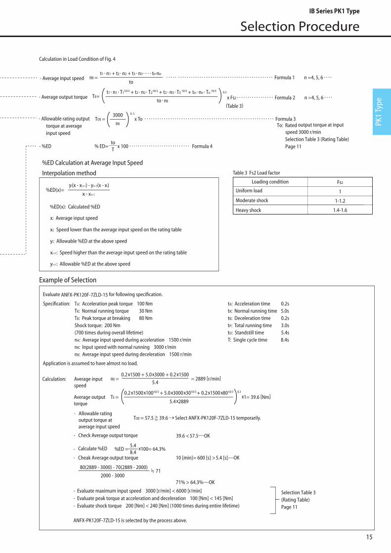
Selection Procedure
Flow Chart and Formula of Selection
Fig. 4 Load Pattern
t2
n2
n3n1
tO
T1
T2
T3
tP
t1 t3Time
Time
Inpu
t spe
edO
utpu
t tor
que
T
Evaluate loadcharacteristic
Selection Table 3 (Rating Table) Page 11-12
TE < TAE
andTE TOE
Select tentativeframe size
Check peak torque acceleration and deceleration
%ED
%ED at certain speed.(Caculate value by interpolationwhen there is no speed indicatedin Selection Table 3 (Rating Table))
Check input speedCheck
( )
Calculate of average input speed (nE)Calculate of average output torque (TE)
Calculate of allowable rating outputtorque at average input speed TOE
NO
NO
NONO
NO
NO
Complete
Check dimension of servo motor attachment part
Raise frame size
Make stop time longeror
reduce speed
Determine output following page 58Actual load moment allowable momentCalculated main bearing lifetime requested lifetime*Calculation is theoretical.
NO
Lower maximumspeed
Select larger size orlower average output torque. TE
Radial load at output shaftAxial load at output shaftMoment load
Maximuminput speed
Allowablemaximuminput speed
Peak torqueat accelerationand deceleration
Allowablepeak torque atacceleration anddeceleration
Raise frame size
Raise frame size
Selection Table 3 (Rating Table) Page 11
Selection Table 3 (Rating Table) Page 11
Selection Table 3 (Allowable External Rating) Page 13
Calculation of %ED
Selection Table 3 (Rating Table) Page 12
Selection Table 3 (Rating Table) Page 11
Check shock torque
Shock torque
Allowable peaktorque foremergency stop
Check motor flange code
Determine nomenclature
Select frame size
Actual radialload, axialload, or moment
Allowable radialload, axial load,or moment
<=
<= <=
<=
<=
<=
<=<=
n1: Average input speed at
acceleration when as in
Fig 4:
n2: Input speed at normal
operation
n3: Average input speed at
deceleration when as in
Fig 4:
t1: Acceleration time [s]t2: Steady operation time [s]t3: Deceleration time [s]tO: Operation time [s]tP: Stop time [s]T: Operation cycle [s]T1: Starting peak torque [Nm]T2: Steady operation torque
[Nm]T3: Stopping peak torque
[Nm]n1=n3= 2
n2
[r/min]
n1= 2n2
[r/min]
IB Series PK1 Type
PK1
Type
15
Selection Procedure
Table 3 Fs2 Load factor
Uniform load
Moderate shock
Heavy shock
Loading condition Fs2
1
1-1.2
1.4-1.6
Example of Selection
- Average input speed
- Average output torque
- Allowable rating output torque at average input speed
nE = t1 · n1 + t2 · n2 + t3 · n3 · · · · tn·nn
· · · · · · · · · · · · · · · · · · · · · · · · · · · · · · · · · · · · · · · · · · · · · · · · · Formula 1 n =4, 5, 6 · · · ·to
TE= t1 · n1 · T110/3 + t2 · n2 · T210/3 + t3 · n3 · T3 10/3 + tn · nn · Tn 10/3
to · nE
- %ED % ED= T
x 100 · · · · · · · · · · · · · · · · · · · · · · · · · · · · Formula 4
TOE = 0. 3
x To · · · · · · · · · · · · · · · · · · · · · · · · · · · · · · · · · · · · · · · · · · · · · · · · · · · · · · · · · · · · Formula 3
to
nE
3000
To: Rated output torque at input speed 3000 r/min
Selection Table 3 (Rating Table) Page 11
0.3
x Fs2 · · · · · · · · · · · · · · · · · Formula 2 n =4, 5, 6 · · · ·
(Table 3)
Calculation in Load Condition of Fig. 4
Evaluate ANFX-PK120F-7ZLD-15 for following specification.
Application is assumed to have almost no load.
TA: Acceleration peak torque 100 NmTR: Normal running torque 30 NmTB: Peak torque at breaking 80 NmShock torque: 200 Nm (700 times during overall lifetime)nA: Average input speed during acceleration 1500 r/minnR: Input speed with normal running 3000 r/minnB: Average input speed during deceleration 1500 r/min
tA: Acceleration time 0.2stR: Normal running time 5.0stB: Deceleration time 0.2stP: Total running time 3.0stO: Standstill time 5.4sT: Single cycle time 8.4s
Specification:
Calculation: Average input speed
- Calculate %ED %ED = 8.4
x 100= 64.3%
- Cheak Average output torque 10 [min]= 600 [s] > 5.4 [s].....OK
71% > 64.3%.....OK
- Evaluate maximum input speed 3000 [r/min] < 6000 [r/min] - Evaluate peak torque at acceleration and deceleration 100 [Nm] < 145 [Nm] - Evaluate shock torque 200 [Nm] < 240 [Nm] (1000 times during entire lifetime)
ANFX-PK120F-7ZLD-15 is selected by the process above.
nE = 0.2 x 1500 + 5.0 x 3000 + 0.2 x 1500
= 2889 [r/min]
TE = 0.2 x 1500 x 10010/3 + 5.0 x 3000 x 3010/3 + 0.2 x 1500 x 8010/3 0.3
x 1= 39.6 [Nm]
5.4
5.4 x 2889
5.4
TOE = 57.5 >= 39.6 Select ANFX-PK120F-7ZLD-15 temporarily.
- Check Average output torque 39.6 < 57.5.....OK
Selection Table 3(Rating Table) Page 11
%ED Calculation at Average Input Speed
Interpolation method
80(2889 - 3000) - 70(2889 - 2000)
2000 - 3000 71
%ED(x)=yi(x - xi+1) - yi+1(x - xi)
xi - xi+1
%ED(x): Calculated %ED
x: Average input speed
xi: Speed lower than the average input speed on the rating table
xi+1: Speed higher than the average input speed on the rating table
yi: Allowable %ED at the above speed
yi+1: Allowable %ED at the above speed
- Allowable rating output torque at average input speed
Average output torque
.= .
IB Series PK1 Type
16
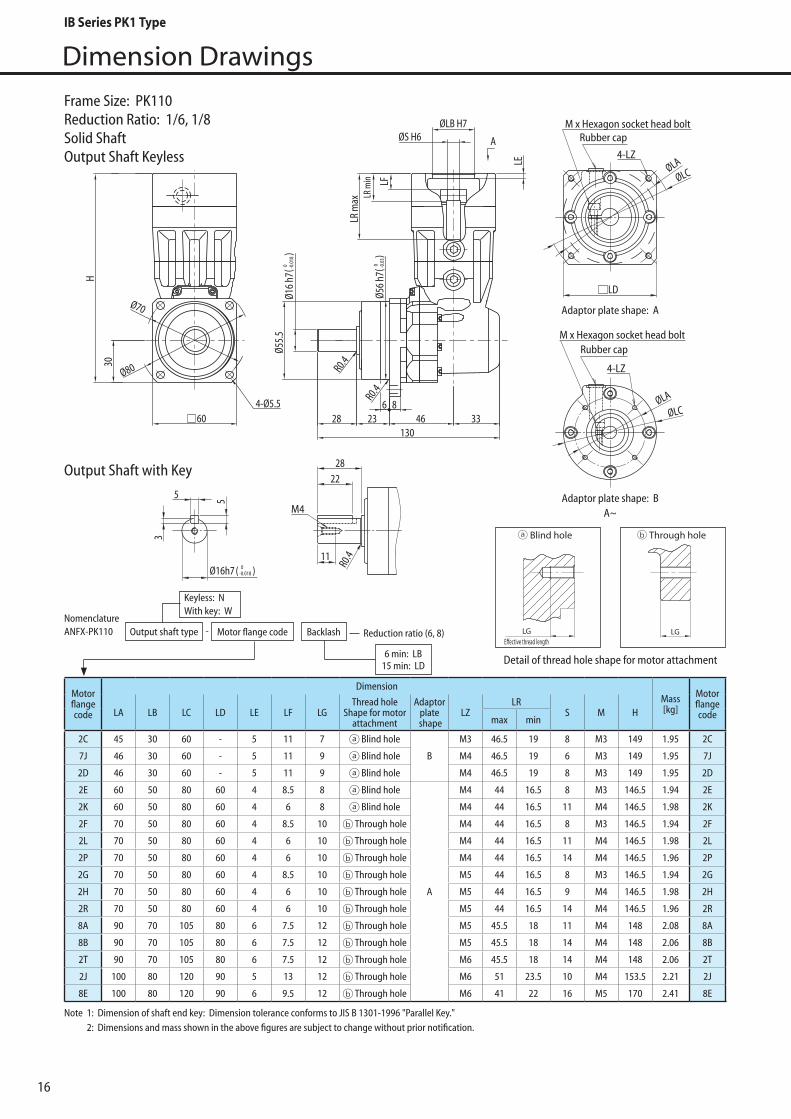
Dimension Drawings
NomenclatureANFX-PK110 Motor flange code Backlash Reduction ratio (6, 8)
6 min: LB15 min: LD
Keyless: N With key: W
-Output shaft type
Note 1: Dimension of shaft end key: Dimension tolerance conforms to JIS B 1301-1996 "Parallel Key." 2: Dimensions and mass shown in the above figures are subject to change without prior notification.
Motorflangecode
DimensionMass[kg]
MotorflangecodeLA LB LC LD LE LF LG
Thread hole Shape for motor
attachment
Adaptorplate
shapeLZ
LRS M H
max min
2C 45 30 60 - 5 11 7 Blind hole
B
M3 46.5 19 8 M3 149 1.95 2C
7J 46 30 60 - 5 11 9 Blind hole M4 46.5 19 6 M3 149 1.95 7J
2D 46 30 60 - 5 11 9 Blind hole M4 46.5 19 8 M3 149 1.95 2D
2E 60 50 80 60 4 8.5 8 Blind hole
A
M4 44 16.5 8 M3 146.5 1.94 2E
2K 60 50 80 60 4 6 8 Blind hole M4 44 16.5 11 M4 146.5 1.98 2K
2F 70 50 80 60 4 8.5 10 Through hole M4 44 16.5 8 M3 146.5 1.94 2F
2L 70 50 80 60 4 6 10 Through hole M4 44 16.5 11 M4 146.5 1.98 2L
2P 70 50 80 60 4 6 10 Through hole M4 44 16.5 14 M4 146.5 1.96 2P
2G 70 50 80 60 4 8.5 10 Through hole M5 44 16.5 8 M3 146.5 1.94 2G
2H 70 50 80 60 4 6 10 Through hole M5 44 16.5 9 M4 146.5 1.98 2H
2R 70 50 80 60 4 6 10 Through hole M5 44 16.5 14 M4 146.5 1.96 2R
8A 90 70 105 80 6 7.5 12 Through hole M5 45.5 18 11 M4 148 2.08 8A
8B 90 70 105 80 6 7.5 12 Through hole M5 45.5 18 14 M4 148 2.06 8B
2T 90 70 105 80 6 7.5 12 Through hole M6 45.5 18 14 M4 148 2.06 2T
2J 100 80 120 90 5 13 12 Through hole M6 51 23.5 10 M4 153.5 2.21 2J
8E 100 80 120 90 6 9.5 12 Through hole M6 41 22 16 M5 170 2.41 8E
4-LZ
M x Hexagon socket head boltRubber cap
M x Hexagon socket head bolt
Adaptor plate shape: A
Adaptor plate shape: BA~
Rubber cap
4-LZØLA
ØLC
LD
ØLA
ØLC
M4
11
R0.4
2228
Ø16h7 ( 0-0.018 )
55
3
( 0 -0.0
3)
( 0 -0.0
18)
30
60
Ø56
h7
6 823 46 33
130
A
Ø55.
5
R0.4
Ø16
h7
R0.4
284-Ø5.5
Ø70
Ø80
H
ØLB H7ØS H6
LR m
ax LR m
in LF
LE
Frame Size: PK110Reduction Ratio: 1/6, 1/8Solid ShaftOutput Shaft Keyless
Detail of thread hole shape for motor attachment
LGE�ective thread length
Blind hole Through hole With �ange plate
LGE�ective thread length
LGLGE�ective thread length
Blind hole Through hole With �ange plate
LGE�ective thread length
LG
Output Shaft with Key
IB Series PK1 Type

17
Dimension Drawings
PK1
Type
Motorflangecode
DimensionMass[kg]
MotorflangecodeLA LB LC LD LE LF LG
Thread hole Shape for motor
attachment
Adaptorplate
shapeLZ
LRS M H
max min
2C 45 30 60 - 5 11 7 Blind hole
B
M3 46.5 19 8 M3 149 1.95 2C
7J 46 30 60 - 5 11 9 Blind hole M4 46.5 19 6 M3 149 1.95 7J
2D 46 30 60 - 5 11 9 Blind hole M4 46.5 19 8 M3 149 1.95 2D
2E 60 50 80 60 4 8.5 8 Blind hole
A
M4 44 16.5 8 M3 146.5 1.94 2E
2K 60 50 80 60 4 6 8 Blind hole M4 44 16.5 11 M4 146.5 1.98 2K
2F 70 50 80 60 4 8.5 10 Through hole M4 44 16.5 8 M3 146.5 1.94 2F
2L 70 50 80 60 4 6 10 Through hole M4 44 16.5 11 M4 146.5 1.98 2L
2G 70 50 80 60 4 8.5 10 Through hole M5 44 16.5 8 M3 146.5 1.94 2G
2H 70 50 80 60 4 6 10 Through hole M5 44 16.5 9 M4 146.5 1.98 2H
2R 70 50 80 60 4 6 10 Through hole M5 44 16.5 14 M4 146.5 1.96 2R
8A 90 70 105 80 6 7.5 12 Through hole M5 45.5 18 11 M4 148 2.08 8A
8B 90 70 105 80 6 7.5 12 Through hole M5 45.5 18 14 M4 148 2.06 8B
2T 90 70 105 80 6 7.5 12 Through hole M6 45.5 18 14 M4 148 2.06 2T
2J 100 80 120 90 5 13 12 Through hole M6 51 23.5 10 M4 153.5 2.21 2J
8E 100 80 120 90 6 9.5 12 Through hole M6 41 22 16 M5 170 2.41 8E
Note 1: Dimension of shaft end key: Dimension tolerance conforms to JIS B 1301-1996 "Parallel Key." 2: Dimensions and mass shown in the above figures are subject to change without prior notification.
4-LZ
M x Hexagon socket head boltRubber cap
M x Hexagon socket head bolt
Adaptor plate shape: A
Adaptor plate shape: BA~
Rubber cap
4-LZØLA
ØLC
LD
ØLA
ØLC
M4
11
R0.4
2228
Ø16h7 ( 0-0.018 )
55
3
( 0 -0.0
3)
( 0 -0.0
18)
30
60
Ø56
h7
6 823 46 33
130
A
Ø55.
5
R0.4
Ø16
h7
R0.4
284-Ø5.5
Ø70
Ø80
H
ØLB H7ØS H6
LR m
ax LR m
in LF
LE
Frame Size: PK110Reduction Ratio: 1/11, 1/15, 1/27Solid ShaftOutput Shaft Keyless
NomenclatureANFX-PK110 Motor flange code Backlash Reduction ratio (11, 15, 27)
6 min: LB15 min: LD
Keyless: N With key: W
-Output shaft type
Detail of thread hole shape for motor attachment
LGE�ective thread length
Blind hole Through hole With �ange plate
LGE�ective thread length
LGLGE�ective thread length
Blind hole Through hole With �ange plate
LGE�ective thread length
LG
Output Shaft with Key
IB Series PK1 Type
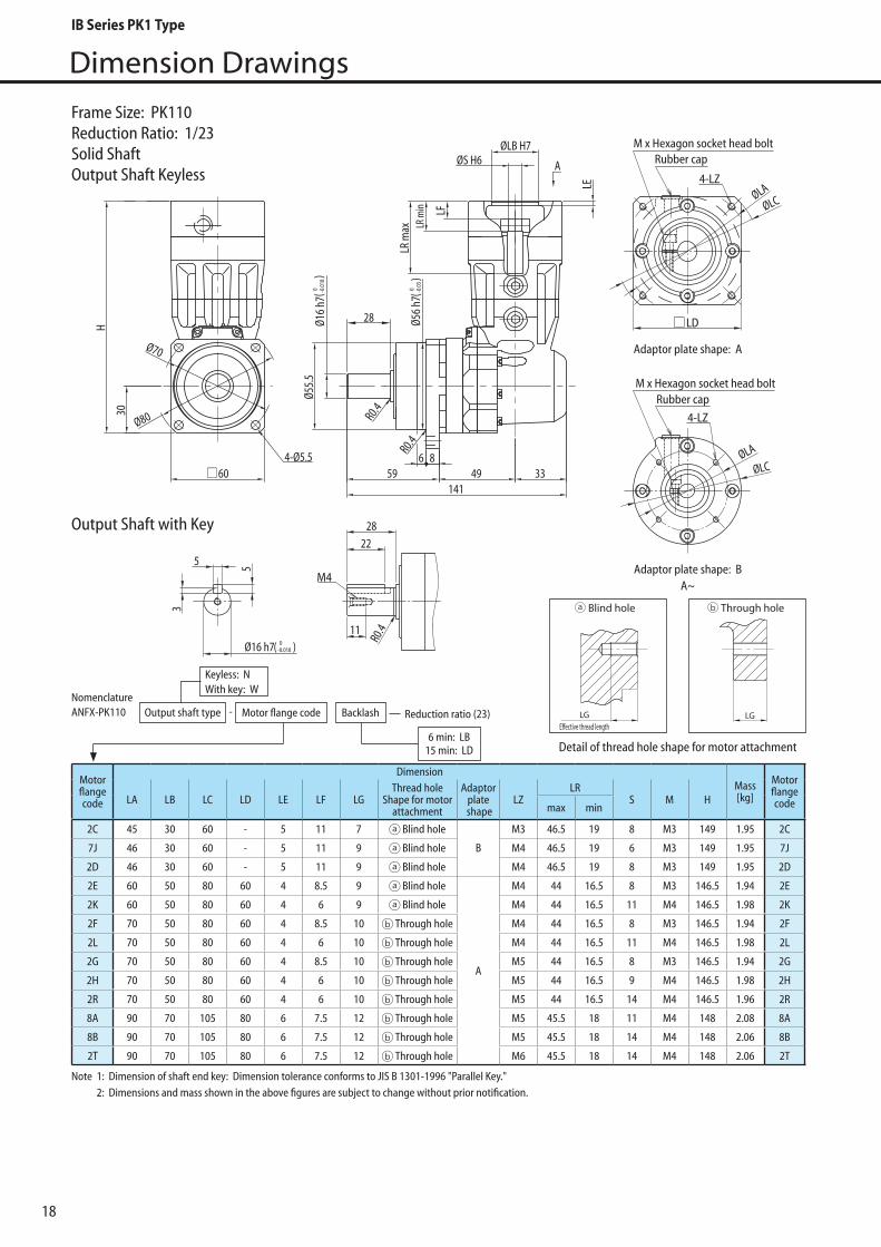
18
Dimension Drawings
4-LZ
M x Hexagon socket head boltRubber cap
M x Hexagon socket head boltRubber cap
4-LZØLA
ØLC
ØLA
ØLC
LD
30
60
Ø56
h7
6 859 49 33
141
A
Ø55.
5
R0.4
Ø16
h7
R0.4
4-Ø5.5
Ø70
Ø80
28
H
LR m
ax
ØLB H7ØS H6
LR m
in LF
LEM4
11
R0.4
2228
Ø16 h7( 0-0.018 )
55
3
( 0 -0.0
3)
( 0 -0.0
18)
Adaptor plate shape: A
Adaptor plate shape: BA~
Frame Size: PK110Reduction Ratio: 1/23Solid ShaftOutput Shaft Keyless
Motorflangecode
DimensionMass[kg]
MotorflangecodeLA LB LC LD LE LF LG
Thread hole Shape for motor
attachment
Adaptorplate
shapeLZ
LRS M H
max min
2C 45 30 60 - 5 11 7 Blind hole
B
M3 46.5 19 8 M3 149 1.95 2C
7J 46 30 60 - 5 11 9 Blind hole M4 46.5 19 6 M3 149 1.95 7J
2D 46 30 60 - 5 11 9 Blind hole M4 46.5 19 8 M3 149 1.95 2D
2E 60 50 80 60 4 8.5 9 Blind hole
A
M4 44 16.5 8 M3 146.5 1.94 2E
2K 60 50 80 60 4 6 9 Blind hole M4 44 16.5 11 M4 146.5 1.98 2K
2F 70 50 80 60 4 8.5 10 Through hole M4 44 16.5 8 M3 146.5 1.94 2F
2L 70 50 80 60 4 6 10 Through hole M4 44 16.5 11 M4 146.5 1.98 2L
2G 70 50 80 60 4 8.5 10 Through hole M5 44 16.5 8 M3 146.5 1.94 2G
2H 70 50 80 60 4 6 10 Through hole M5 44 16.5 9 M4 146.5 1.98 2H
2R 70 50 80 60 4 6 10 Through hole M5 44 16.5 14 M4 146.5 1.96 2R
8A 90 70 105 80 6 7.5 12 Through hole M5 45.5 18 11 M4 148 2.08 8A
8B 90 70 105 80 6 7.5 12 Through hole M5 45.5 18 14 M4 148 2.06 8B
2T 90 70 105 80 6 7.5 12 Through hole M6 45.5 18 14 M4 148 2.06 2T
Note 1: Dimension of shaft end key: Dimension tolerance conforms to JIS B 1301-1996 "Parallel Key." 2: Dimensions and mass shown in the above figures are subject to change without prior notification.
NomenclatureANFX-PK110 Motor flange code Backlash Reduction ratio (23)
6 min: LB15 min: LD
Keyless: N With key: W
-Output shaft type
Detail of thread hole shape for motor attachment
LGE�ective thread length
Blind hole Through hole With �ange plate
LGE�ective thread length
LGLGE�ective thread length
Blind hole Through hole With �ange plate
LGE�ective thread length
LG
Output Shaft with Key
IB Series PK1 Type

19
Dimension Drawings
PK1
Type
4-LZ
M x Hexagon socket head boltRubber cap
M x Hexagon socket head boltRubber cap
4-LZØLA
ØLC
ØLA
ØLC
LD
30
60
Ø56
h7
6 859 49 33
141
A
Ø55.
5
R0.4
Ø16
h7
R0.4
4-Ø5.5
Ø70
Ø80
28
H
LR m
ax
ØLB H7ØS H6
LR m
in LF
LE
M4
11
R0.4
2228
Ø16 h7( 0-0.018 )
55
3
( 0 -0.0
3)
( 0 -0.0
18)
Adaptor plate shape: A
Adaptor plate shape: BA~
Frame Size: PK110Reduction Ratio: 1/33Solid ShaftOutput Shaft Keyless
Motorflangecode
DimensionMass[kg]
MotorflangecodeLA LB LC LD LE LF LG
Thread hole Shape for motor
attachment
Adaptorplate
shapeLZ
LRS M H
max min
2C 45 30 60 - 5 11 7 Blind hole
B
M3 46.5 19 8 M3 149 1.95 2C
7J 46 30 60 - 5 11 9 Blind hole M4 46.5 19 6 M3 149 1.95 7J
2D 46 30 60 - 5 11 9 Blind hole M4 46.5 19 8 M3 149 1.95 2D
2E 60 50 80 60 4 8.5 9 Blind hole
A
M4 44 16.5 8 M3 146.5 1.94 2E
2K 60 50 80 60 4 6 9 Blind hole M4 44 16.5 11 M4 146.5 1.98 2K
2F 70 50 80 60 4 8.5 10 Through hole M4 44 16.5 8 M3 146.5 1.94 2F
2L 70 50 80 60 4 6 10 Through hole M4 44 16.5 11 M4 146.5 1.98 2L
2G 70 50 80 60 4 8.5 10 Through hole M5 44 16.5 8 M3 146.5 1.94 2G
2H 70 50 80 60 4 6 10 Through hole M5 44 16.5 9 M4 146.5 1.98 2H
2R 70 50 80 60 4 6 10 Through hole M5 45.5 16.5 14 M4 146.5 1.96 2R
8A 90 70 105 80 6 7.5 12 Through hole M5 45.5 18 11 M4 148 2.08 8A
2T 90 70 105 80 6 7.5 12 Through hole M6 45.5 18 14 M4 148 2.06 2T
Note 1: Dimension of shaft end key: Dimension tolerance conforms to JIS B 1301-1996 "Parallel Key." 2: Dimensions and mass shown in the above figures are subject to change without prior notification.
NomenclatureANFX-PK110 Motor flange code Backlash Reduction ratio (33)
6 min: LB15 min: LD
Keyless: N With key: W
-Output shaft type
Detail of thread hole shape for motor attachment
LGE�ective thread length
Blind hole Through hole With �ange plate
LGE�ective thread length
LGLGE�ective thread length
Blind hole Through hole With �ange plate
LGE�ective thread length
LG
Output Shaft with Key
IB Series PK1 Type

20
Dimension Drawings
Motorflangecode
DimensionMass[kg]
MotorflangecodeLA LB LC LD LE LF LG
Thread hole Shape for motor
attachment
Adaptorplate
shapeLZ
LRS M H
max min
2C 45 30 60 - 5 11 7 Blind hole
B
M3 46.5 19 8 M3 149 2.20 2C
7J 46 30 60 - 5 11 9 Blind hole M4 46.5 19 6 M3 149 2.20 7J
2D 46 30 60 - 5 11 9 Blind hole M4 46.5 19 8 M3 149 2.20 2D
2E 60 50 80 60 4 8.5 9 Blind hole
A
M4 44 16.5 8 M3 146.5 2.19 2E
2F 70 50 80 60 4 8.5 10 Through hole M4 44 16.5 8 M3 146.5 2.19 2F
2G 70 50 80 60 4 8.5 10 Through hole M5 44 16.5 8 M3 146.5 2.19 2G
2H 70 50 80 60 4 6 10 Through hole M5 44 16.5 9 M4 146.5 2.23 2H
2R 70 50 80 60 4 6 10 Through hole M5 44 16.5 14 M4 146.5 1.96 2R
2T 90 70 105 80 6 7.5 12 Through hole M6 45.5 18 14 M4 148 2.06 2T
Note 1: Dimension of shaft end key: Dimension tolerance conforms to JIS B 1301-1996 "Parallel Key." 2: Dimensions and mass shown in the above figures are subject to change without prior notification.
4-LZ
M x Hexagon socket head boltRubber cap
M x Hexagon socket head boltRubber cap
4-LZØLA
ØLC
ØLA
ØLC
LD
30
60
Ø56
h7
6 859 49 33
141
A
Ø55.
5
R0.4
Ø16
h7
R0.4
4-Ø5.5
Ø70
Ø80
28
H
LR m
ax
ØLB H7ØS H6
LR m
in LF
LEM4
11
R0.4
2228
Ø16h7( 0-0.018 )
55
3
( 0 -0.0
3)
( 0 -0.0
18)
Adaptor plate shape: A
Adaptor plate shape: BA~
NomenclatureANFX-PK110 Motor flange code Backlash Reduction ratio (45, 50, 63, 68)
6 min: LB15 min: LD
Keyless: N With key: W
-Output shaft type
Frame Size: PK110Reduction Ratio: 1/45, 1/50, 1/63, 1/68Solid ShaftOutput Shaft Keyless
Detail of thread hole shape for motor attachment
LGE�ective thread length
Blind hole Through hole With �ange plate
LGE�ective thread length
LGLGE�ective thread length
Blind hole Through hole With �ange plate
LGE�ective thread length
LG
Output Shaft with Key
IB Series PK1 Type

21
Dimension Drawings
PK1
Type
4-LZ
M x Hexagon socket head boltRubber cap
M x Hexagon socket head boltRubber cap
4-LZØLA
ØLC
ØLA
ØLC
LD
30
60
Ø56
h7
6 859 49 33
141
A
Ø55.
5
R0.4
Ø16
h7
R0.4
4-Ø5.5
Ø70
Ø80
28
H
LR m
ax
ØLB H7ØS H6
LR m
in LF
LE
M4
11
R0.4
2228
Ø16h7( 0-0.018 )
55
3
( 0 -0.0
3)
( 0 -0.0
18)
Adaptor plate shape: A
Adaptor plate shape: BA~
Frame Size: PK110Reduction Ratio: 1/99, 1/122, 1/135, 1/243Solid ShaftOutput Shaft Keyless
Motorflangecode
DimensionMass[kg]
MotorflangecodeLA LB LC LD LE LF LG
Thread hole Shape for motor
attachment
Adaptorplate
shapeLZ
LRS M H
max min
2C 45 30 60 - 5 11 7 Blind hole
B
M3 46.5 19 8 M3 149 2.20 2C
7J 46 30 60 - 5 11 9 Blind hole M4 46.5 19 6 M3 149 2.20 7J
2D 46 30 60 - 5 11 9 Blind hole M4 46.5 19 8 M3 149 2.20 2D
2E 60 50 80 60 4 8.5 9 Blind hole
A
M4 44 16.5 8 M3 146.5 2.19 2E
2H 70 50 80 60 4 6 10 Through hole M5 44 16.5 9 M4 146.5 2.23 2H
2R 70 50 80 60 4 6 10 Through hole M5 44 16.5 14 M4 146.5 1.96 2R
2T 90 70 105 80 6 7.5 12 Through hole M6 45.5 18 14 M4 148 2.06 2T
Note 1: Dimension of shaft end key: Dimension tolerance conforms to JIS B 1301-1996 "Parallel Key." 2: Dimensions and mass shown in the above figures are subject to change without prior notification.
NomenclatureANFX-PK110 Motor flange code Backlash Reduction ratio (99, 122, 135, 243)
6 min: LB15 min: LD
Keyless: N With key: W
-Output shaft type
Detail of thread hole shape for motor attachment
LGE�ective thread length
Blind hole Through hole With �ange plate
LGE�ective thread length
LGLGE�ective thread length
Blind hole Through hole With �ange plate
LGE�ective thread length
LG
Output Shaft with Key
IB Series PK1 Type

22
Dimension Drawings
Frame Size: PK120Reduction Ratio: 1/6Solid ShaftOutput Shaft Keyless
45H
68 46.5185.5
LR m
axLR
min
A
ØLB H7
ØS H6
LE
Ø25
h7 Ø
85 h
7
10 1071
R0.4
42Ø105Ø120
90
4-Ø9
45°
M6
4
8
7
Ø25 h7 ( 0-0.021 )
3242
15 R0.4
( 0 -0.0
21)
( 0 -0.0
35)
R0.4
Adaptor plate shape: AA~
Rubber cap4-LZ
M x Hexagon socket head bolt
ØLCØLA
LD
Note 1: Dimension of shaft end key: Dimension tolerance conforms to JIS B 1301-1996 "Parallel Key." 2: Dimension of coupling of motor flange code (0V) includes tolerance (+0.012 ~ +0.023) 3: Dimensions and mass shown in the above figures are subject to change without prior notification.
Motorflangecode
DimensionMass[kg]
MotorflangecodeLA LB LC LD LE LF LG
Thread hole Shape for motor
attachment
Adaptorplate
shapeLZ
LRS M H
max min
0U 90 70 105 81 6 6 12 Through hole
A
M5 50 18.5 16 M5 183 5.0 0U
7S 90 70 105 81 6 6 12 Through hole M5 50 18.5 19 M5 183 5.0 7S
7P 90 70 105 81 6 6 12 Through hole M6 50 18.5 16 M5 183 5.0 7P
1G 90 70 105 81 6 6 12 Through hole M6 50 18.5 19 M5 183 5.0 1G
0V 100 80 120 90 5 21.5 12 Through hole M6 63.5 32 14 M4 196.5 5.1 0V
8E 100 80 120 90 5 19.5 12 Through hole M6 63.5 32 16 M5 196.5 5.1 8E
7V 100 80 120 90 5 19.5 12 Through hole M6 63.5 32 19 M5 196.5 5.1 7V
1L 115 95 135 100 6 17 16 Through hole M6 46 31.5 24 M6 209.5 5.5 1L
7A 115 95 135 100 6 19.5 16 Through hole M8 63.5 32 16 M5 196.5 5.2 7A
7B 115 95 135 100 6 19.5 16 Through hole M8 63.5 32 19 M5 196.5 5.2 7B
0W 115 95 135 100 6 17 16 Through hole M8 46 31.5 22 M6 209.5 5.5 0W
7Y 115 95 135 100 6 17 16 Through hole M8 46 31.5 24 M6 209.5 5.5 7Y
0Y 135 110 165 120 7 17 16 Through hole M8 46 31.5 22 M6 209.5 5.6 0Y
7R 145 110 165 120 7 22.5 16 Through hole M8 66.5 35 16 M5 199.5 5.4 7R
7X 145 110 165 120 7 22.5 16 Through hole M8 66.5 35 19 M5 199.5 5.3 7X
1S 145 110 165 120 7 42 16 Through hole M8 71 56.5 22 M6 234.5 5.8 1S
7Z 145 110 165 120 7 42 16 Through hole M8 71 56.5 24 M6 234.5 5.8 7Z
*2 *2
NomenclatureANFX-PK120 Motor flange code Backlash Reduction ratio (6)
6 min: LB15 min: LD
Keyless: N With key: W
-Output shaft type
Detail of thread hole shape for motor attachment
LGE�ective thread length
Blind hole Through hole With �ange plate
LGE�ective thread length
LG
Output Shaft with Key
IB Series PK1 Type

23
Dimension Drawings
PK1
Type
Adaptor plate shape: A
Adaptor plate shape: BA~
4-LZ
M x Hexagon socket head boltRubber cap
Rubber cap4-LZ
M x Hexagon socket head bolt
ØLCØLA
ØLA
ØLC
45H
68 46.5185.5
LR m
axLR
min
A
ØLB H7
ØS H6
LE
Ø25
h7 Ø
85 h
7
10 1071
R0.4
42Ø105Ø120
LD
LD
90
4-Ø9
45°
M6
4
8
7
Ø25 h7( 0-0.021 )
3242
15 R0.4
( 0 -0.0
21)
( 0 -0.0
35)
R0.4
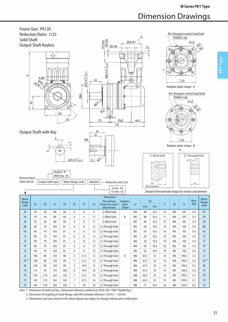
Frame Size: PK120Reduction Ratio: 1/8Solid ShaftOutput Shaft Keyless
Note 1: Dimension of shaft end key: Dimension tolerance conforms to JIS B 1301-1996 "Parallel Key." 2: Dimension of coupling of motor flange code (0V) includes tolerance (+0.012 ~ +0.023) 3: Dimensions and mass shown in the above figures are subject to change without prior notification.
Motorflangecode
DimensionMass[kg]
MotorflangecodeLA LB LC LD LE LF LG
Thread hole Shape for motor
attachment
Adaptorplate
shapeLZ
LRS M H
max min
2R 70 50 80 60 6 6 11 Blind hole B M5 48 16.5 14 M4 181 5.0 2R
0U 90 70 105 81 6 6 12 Through hole
A
M5 50 18.5 16 M5 183 5.0 0U
7S 90 70 105 81 6 6 12 Through hole M5 50 18.5 19 M5 183 5.0 7S
7P 90 70 105 81 6 6 12 Through hole M6 50 18.5 16 M5 183 5.0 7P
1G 90 70 105 81 6 6 12 Through hole M6 50 18.5 19 M5 183 5.0 1G
2J 100 80 120 90 5 21.5 12 Through hole M6 63.5 32 10 M4 196.5 5.1 2J
0V 100 80 120 90 5 21.5 12 Through hole M6 63.5 32 14 M4 196.5 5.1 0V
8E 100 80 120 90 5 19.5 12 Through hole M6 63.5 32 16 M5 196.5 5.1 8E
7V 100 80 120 90 5 19.5 12 Through hole M6 63.5 32 19 M5 196.5 5.1 7V
1L 115 95 135 100 6 17 16 Through hole M6 46 31.5 24 M6 209.5 5.5 1L
7A 115 95 135 100 6 19.5 16 Through hole M8 63.5 32 16 M5 196.5 5.2 7A
7B 115 95 135 100 6 19.5 16 Through hole M8 63.5 32 19 M5 196.5 5.2 7B
0W 115 95 135 100 6 17 16 Through hole M8 46 31.5 22 M6 209.5 5.5 0W
7Y 115 95 135 100 6 17 16 Through hole M8 46 31.5 24 M6 209.5 5.5 7Y
0Y 135 110 165 120 7 17 16 Through hole M8 46 31.5 22 M6 209.5 5.6 0Y
7R 145 110 165 120 7 22.5 16 Through hole M8 66.5 35 16 M5 199.5 5.4 7R
7X 145 110 165 120 7 22.5 16 Through hole M8 66.5 35 19 M5 199.5 5.3 7X
1S 145 110 165 120 7 42 16 Through hole M8 71 56.5 22 M6 234.5 5.8 1S
7Z 145 110 165 120 7 42 16 Through hole M8 71 56.5 24 M6 234.5 5.8 7Z
*2 *2
NomenclatureANFX-PK120 Motor flange code Backlash Reduction ratio (8)
6 min: LB15 min: LD
Keyless: N With key: W
-Output shaft type
Detail of thread hole shape for motor attachment
LGE�ective thread length
Blind hole Through hole With �ange plate
LGE�ective thread length
LGLGE�ective thread length
Blind hole Through hole With �ange plate
LGE�ective thread length
LG
Output Shaft with Key
IB Series PK1 Type

24
Dimension Drawings
Adaptor plate shape: A
Adaptor plate shape: BA~
M6
4
8
7
Ø25 h7( 0-0.021 )
3242
15 R0.4
45H
68 46.5185.5
LR m
axLR
min
A
ØLB H7ØS H6
LE
Ø25
h7 Ø
85 h
7
10 1071
R0.4
42Ø105Ø120
90
4-Ø9
45°
( 0 -0.0
21)
( 0 -0.0
35)
R0.44-LZ
Rubber capM x Hexagon socket head bolt
Rubber cap
4-LZ
M x Hexagon socket head bolt
ØLCØLA
ØLCØLA
LD
LD
Frame Size: PK120Reduction Ratio: 1/11, 1/15Solid ShaftOutput Shaft Keyless
Note 1: Dimension of shaft end key: Dimension tolerance conforms to JIS B 1301-1996 "Parallel Key." 2: Dimension of coupling of motor flange code (0V) includes tolerance (+0.012 ~ +0.023) 3: Dimensions and mass shown in the above figures are subject to change without prior notification.
Motorflangecode
DimensionMass[kg]
MotorflangecodeLA LB LC LD LE LF LG
Thread hole Shape for motor
attachment
Adaptorplate
shapeLZ
LRS M H
max min
2P 70 50 80 60 6 6 9 Blind holeB
M4 48 16.5 14 M4 181 5.0 2P
2R 70 50 80 60 6 6 11 Blind hole M5 48 16.5 14 M4 181 5.0 2R
8B 90 70 105 81 6 8 12 Through hole
A
M5 50 18.5 14 M4 183 5.0 8B
0U 90 70 105 81 6 6 12 Through hole M5 50 18.5 16 M5 183 5.0 0U
7S 90 70 105 81 6 6 12 Through hole M5 50 18.5 19 M5 183 5.0 7S
2T 90 70 105 81 6 8 12 Through hole M6 50 18.5 14 M4 183 5.0 2T
7P 90 70 105 81 6 6 12 Through hole M6 50 18.5 16 M5 183 5.0 7P
1G 90 70 105 81 6 6 12 Through hole M6 50 18.5 19 M5 183 5.0 1G
2J 100 80 120 90 5 21.5 12 Through hole M6 63.5 32 10 M4 196.5 5.1 2J
0V 100 80 120 90 5 21.5 12 Through hole M6 63.5 32 14 M4 196.5 5.1 0V
8E 100 80 120 90 5 19.5 12 Through hole M6 63.5 32 16 M5 196.5 5.1 8E
7V 100 80 120 90 5 19.5 12 Through hole M6 63.5 32 19 M5 196.5 5.1 7V
1L 115 95 135 100 6 17 16 Through hole M6 46 31.5 24 M6 209.5 5.5 1L
7A 115 95 135 100 6 19.5 16 Through hole M8 63.5 32 16 M5 196.5 5.2 7A
0W 115 95 135 100 6 17 16 Through hole M8 46 31.5 22 M6 209.5 5.5 0W
7Y 115 95 135 100 6 17 16 Through hole M8 46 31.5 24 M6 209.5 5.5 7Y
0Y 135 110 165 120 7 17 16 Through hole M8 46 31.5 22 M6 209.5 5.6 0Y
7R 145 110 165 120 7 22.5 16 Through hole M8 66.5 35 16 M5 199.5 5.4 7R
7X 145 110 165 120 7 22.5 16 Through hole M8 66.5 35 19 M5 199.5 5.3 7X
7Z 145 110 165 120 7 42 16 Through hole M8 71 56.5 24 M6 234.5 5.8 7Z
*2 *2
NomenclatureANFX-PK120 Motor flange code Backlash Reduction ratio (11, 15)
6 min: LB15 min: LD
Keyless: N With key: W
-Output shaft type
Detail of thread hole shape for motor attachment
LGE�ective thread length
Blind hole Through hole With �ange plate
LGE�ective thread length
LGLGE�ective thread length
Blind hole Through hole With �ange plate
LGE�ective thread length
LG
Output Shaft with Key
IB Series PK1 Type
25
Dimension Drawings
PK1
Type
4-LZRubber cap
M x Hexagon socket head bolt
Rubber cap
4-LZ
M x Hexagon socket head bolt
ØLCØLA
ØLCØLA
M6
4
8
7
Ø25 h7( 0-0.021)
3242
15 R0.4
73.5 46.5
A
191
45H
ØLB H7ØS H6LR
min
LE
73.571
Ø25
h7 Ø
85 h
7
10 1071
R0.4
Ø84
R0.4
42Ø105Ø120LD
LD
90
4-Ø9
LR m
ax
45°
( 0 -0.0
21)
( 0 -0.0
35)
Adaptor plate shape: A
Adaptor plate shape: BA~
Frame Size: PK120Reduction Ratio: 1/23Solid ShaftOutput Shaft Keyless
Note 1: Dimension of shaft end key: Dimension tolerance conforms to JIS B 1301-1996 "Parallel Key." 2: Dimension of coupling of motor flange code (0V) includes tolerance (+0.012 ~ +0.023) 3: Dimensions and mass shown in the above figures are subject to change without prior notification.
Motorflangecode
DimensionMass[kg]
MotorflangecodeLA LB LC LD LE LF LG
Thread hole Shape for motor
attachment
Adaptorplate
shapeLZ
LRS M H
max min
2P 70 50 80 60 6 6 9 Blind hole
B
M4 48 16.5 14 M4 181 5.4 2P
2H 70 50 80 60 6 6 11 Blind hole M5 48 16.5 9 M4 181 5.3 2H
2R 70 50 80 60 6 6 11 Blind hole M5 48 16.5 14 M4 181 5.4 2R
8B 90 70 105 81 6 8 12 Through hole
A
M5 50 18.5 14 M4 183 5.4 8B
0U 90 70 105 81 6 6 12 Through hole M5 50 18.5 16 M5 183 5.4 0U
7S 90 70 105 81 6 6 12 Through hole M5 50 18.5 19 M5 183 5.4 7S
2T 90 70 105 81 6 8 12 Through hole M6 50 18.5 14 M4 183 5.4 2T
7P 90 70 105 81 6 6 12 Through hole M6 50 18.5 16 M5 183 5.4 7P
1G 90 70 105 81 6 6 12 Through hole M6 50 18.5 19 M5 183 5.4 1G
2J 100 80 120 90 5 21.5 12 Through hole M6 63.5 32 10 M4 196.5 5.5 2J
0V 100 80 120 90 5 21.5 12 Through hole M6 63.5 32 14 M4 196.5 5.5 0V
8E 100 80 120 90 5 19.5 12 Through hole M6 63.5 32 16 M5 196.5 5.5 8E
7A 115 95 135 100 6 19.5 16 Through hole M8 63.5 32 16 M5 196.5 5.6 7A
7R 145 110 165 120 7 22.5 16 Through hole M8 66.5 35 16 M5 199.5 5.7 7R
7X 145 110 165 120 7 22.5 16 Through hole M8 66.5 35 19 M5 199.5 5.7 7X
7Z 145 110 165 120 7 42 16 Through hole M8 71 56.5 24 M6 234.5 6.2 7Z
*2 *2
NomenclatureANFX-PK120 Motor flange code Backlash Reduction ratio (23)
6 min: LB15 min: LD
Keyless: N With key: W
-Output shaft type
Detail of thread hole shape for motor attachment
LGE�ective thread length
Blind hole Through hole With �ange plate
LGE�ective thread length
LGLGE�ective thread length
Blind hole Through hole With �ange plate
LGE�ective thread length
LG
Output Shaft with Key
IB Series PK1 Type

26
Dimension Drawings
M6
4
8
7
Ø25 h7( 0-0.021 )
3242
15 R0.4
Adaptor plate shape: A
Adaptor plate shape: BA~
4-LZRubber cap
M x Hexagon socket head bolt
Rubber cap
4-LZ
M x Hexagon socket head bolt
ØLCØLA
ØLCØLA45H
68 46.5185.5
LR m
axLR
min
A
ØLB H7ØS H6
LE
Ø25
h7 Ø
85 h
7
10 1071
R0.4
42Ø105Ø120
LD
LD
90
4-Ø9
45°
( 0 -0.0
21)
( 0 -0.0
35)
R0.4
Frame Size: PK120Reduction Ratio: 1/27Solid ShaftOutput Shaft Keyless
Note 1: Dimension of shaft end key: Dimension tolerance conforms to JIS B 1301-1996 "Parallel Key." 2: Dimension of coupling of motor flange code (0V) includes tolerance (+0.012 ~ +0.023) 3: Dimensions and mass shown in the above figures are subject to change without prior notification.
Motorflangecode
DimensionMass[kg]
MotorflangecodeLA LB LC LD LE LF LG
Thread hole Shape for motor
attachment
Adaptorplate
shapeLZ
LRS M H
max min
2P 70 50 80 60 6 6 9 Blind hole
B
M4 48 16.5 14 M4 181 5.0 2P
2H 70 50 80 60 6 6 11 Blind hole M5 48 16.5 9 M4 181 5.0 2H
2R 70 50 80 60 6 6 11 Blind hole M5 48 16.5 14 M4 181 5.0 2R
8B 90 70 105 81 6 8 12 Through hole
A
M5 50 18.5 14 M4 183 5.0 8B
0U 90 70 105 81 6 6 12 Through hole M5 50 18.5 16 M5 183 5.0 0U
7S 90 70 105 81 6 6 12 Through hole M5 50 18.5 19 M5 183 5.0 7S
2T 90 70 105 81 6 8 12 Through hole M6 50 18.5 14 M4 183 5.0 2T
7P 90 70 105 81 6 6 12 Through hole M6 50 18.5 16 M5 183 5.0 7P
1G 90 70 105 81 6 6 12 Through hole M6 50 18.5 19 M5 183 5.0 1G
2J 100 80 120 90 5 21.5 12 Through hole M6 63.5 32 10 M4 196.5 5.1 2J
0V 100 80 120 90 5 21.5 12 Through hole M6 63.5 32 14 M4 196.5 5.1 0V
8E 100 80 120 90 5 19.5 12 Through hole M6 63.5 32 16 M5 196.5 5.1 8E
7A 115 95 135 100 6 19.5 16 Through hole M8 63.5 32 16 M5 196.5 5.2 7A
7R 145 110 165 120 7 22.5 16 Through hole M8 66.5 35 16 M5 199.5 5.4 7R
7X 145 110 165 120 7 22.5 16 Through hole M8 66.5 35 19 M5 199.5 5.3 7X
7Z 145 110 165 120 7 42 16 Through hole M8 71 56.5 24 M6 234.5 5.8 7Z
*2 *2
NomenclatureANFX-PK120 Motor flange code Backlash Reduction ratio (27)
6 min: LB15 min: LD
Keyless: N With key: W
-Output shaft type
Detail of thread hole shape for motor attachment
LGE�ective thread length
Blind hole Through hole With �ange plate
LGE�ective thread length
LGLGE�ective thread length
Blind hole Through hole With �ange plate
LGE�ective thread length
LG
Output Shaft with Key
IB Series PK1 Type
27
Dimension Drawings
PK1
Type
Adaptor plate shape: A
Adaptor plate shape: BA~
M6
4
8
7
Ø25 h7( 0-0.021 )
3242
15 R0.4
Rubber cap
4-LZ
M x Hexagon socket head bolt
ØLCØLA
4-LZRubber cap
M x Hexagon socket head bolt
ØLCØLA
73.5 46.5
A
191
45H
ØLB H7ØS H6LR
min
LE
73.571
Ø25
h7 Ø
85 h
7
10 1071
R0.4
Ø84
R0.4
42Ø105Ø120
LD
LD
90
4-Ø9
LR m
ax
45°
( 0 -0.0
21)
( 0 -0.0
35)
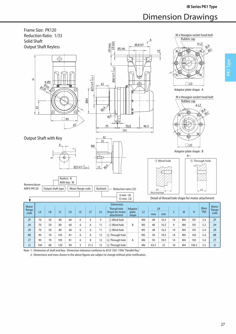
Motorflangecode
DimensionMass[kg]
MotorflangecodeLA LB LC LD LE LF LG
Thread hole Shape for motor
attachment
Adaptorplate
shapeLZ
LRS M H
max min
2P 70 50 80 60 6 6 9 Blind hole
B
M4 48 16.5 14 M4 181 5.4 2P
2H 70 50 80 60 6 6 11 Blind hole M5 48 16.5 9 M4 181 5.3 2H
2R 70 50 80 60 6 6 11 Blind hole M5 48 16.5 14 M4 181 5.4 2R
8B 90 70 105 81 6 8 12 Through hole
A
M5 50 18.5 14 M4 183 5.4 8B
2T 90 70 105 81 6 8 12 Through hole M6 50 18.5 14 M4 183 5.4 2T
2J 100 80 120 90 5 21.5 12 Through hole M6 63.5 32 10 M4 196.5 5.5 2J
Note 1: Dimension of shaft end key: Dimension tolerance conforms to JIS B 1301-1996 "Parallel Key." 2: Dimensions and mass shown in the above figures are subject to change without prior notification.
Frame Size: PK120Reduction Ratio: 1/33Solid ShaftOutput Shaft Keyless
NomenclatureANFX-PK120 Motor flange code Backlash Reduction ratio (33)
6 min: LB15 min: LD
Keyless: N With key: W
-Output shaft type
Detail of thread hole shape for motor attachment
LGE�ective thread length
Blind hole Through hole With �ange plate
LGE�ective thread length
LGLGE�ective thread length
Blind hole Through hole With �ange plate
LGE�ective thread length
LG
Output Shaft with Key
IB Series PK1 Type
28
Dimension Drawings
Adaptor plate shape: A
Adaptor plate shape: BA~
Rubber cap
4-LZ
M x Hexagon socket head bolt
ØLCØLA
4-LZRubber cap
M x Hexagon socket head bolt
ØLCØLA
73.5 46.5
A
191
45H
ØLB H7ØS H6LR
min
LE
73.571
Ø25
h7 Ø
85 h
7
10 1071
R0.4
Ø84
R0.4
42Ø105Ø120
LD
LD
90
4-Ø9
LR m
ax
45°
M6
4
8
7
Ø25 h7( 0-0.021 )
3242
15 R0.4
( 0 -0.0
21)
( 0 -0.0
35)
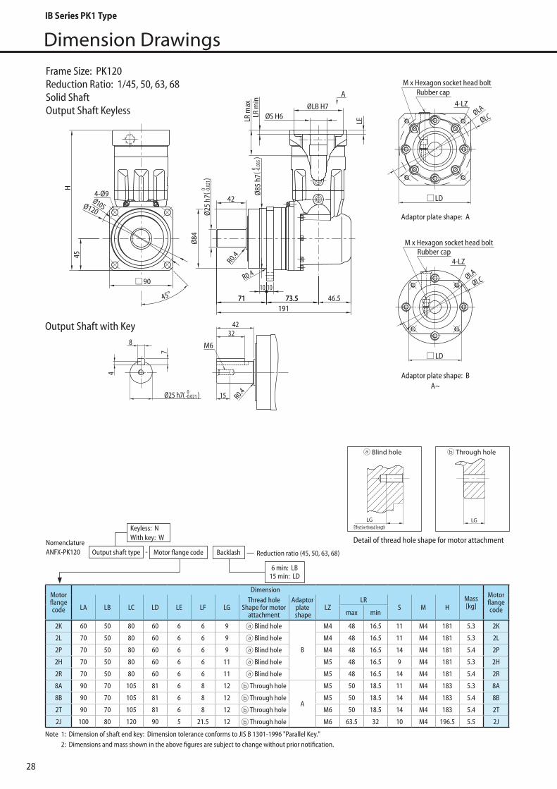
Motorflangecode
DimensionMass[kg]
MotorflangecodeLA LB LC LD LE LF LG
Thread hole Shape for motor
attachment
Adaptorplate
shapeLZ
LRS M H
max min
2K 60 50 80 60 6 6 9 Blind hole
B
M4 48 16.5 11 M4 181 5.3 2K
2L 70 50 80 60 6 6 9 Blind hole M4 48 16.5 11 M4 181 5.3 2L
2P 70 50 80 60 6 6 9 Blind hole M4 48 16.5 14 M4 181 5.4 2P
2H 70 50 80 60 6 6 11 Blind hole M5 48 16.5 9 M4 181 5.3 2H
2R 70 50 80 60 6 6 11 Blind hole M5 48 16.5 14 M4 181 5.4 2R
8A 90 70 105 81 6 8 12 Through hole
A
M5 50 18.5 11 M4 183 5.3 8A
8B 90 70 105 81 6 8 12 Through hole M5 50 18.5 14 M4 183 5.4 8B
2T 90 70 105 81 6 8 12 Through hole M6 50 18.5 14 M4 183 5.4 2T
2J 100 80 120 90 5 21.5 12 Through hole M6 63.5 32 10 M4 196.5 5.5 2J
Note 1: Dimension of shaft end key: Dimension tolerance conforms to JIS B 1301-1996 "Parallel Key." 2: Dimensions and mass shown in the above figures are subject to change without prior notification.
NomenclatureANFX-PK120 Motor flange code Backlash Reduction ratio (45, 50, 63, 68)
6 min: LB15 min: LD
Keyless: N With key: W
-Output shaft type
Frame Size: PK120Reduction Ratio: 1/45, 50, 63, 68Solid ShaftOutput Shaft Keyless
Detail of thread hole shape for motor attachment
LGE�ective thread length
Blind hole Through hole With �ange plate
LGE�ective thread length
LGLGE�ective thread length
Blind hole Through hole With �ange plate
LGE�ective thread length
LG
Output Shaft with Key
IB Series PK1 Type
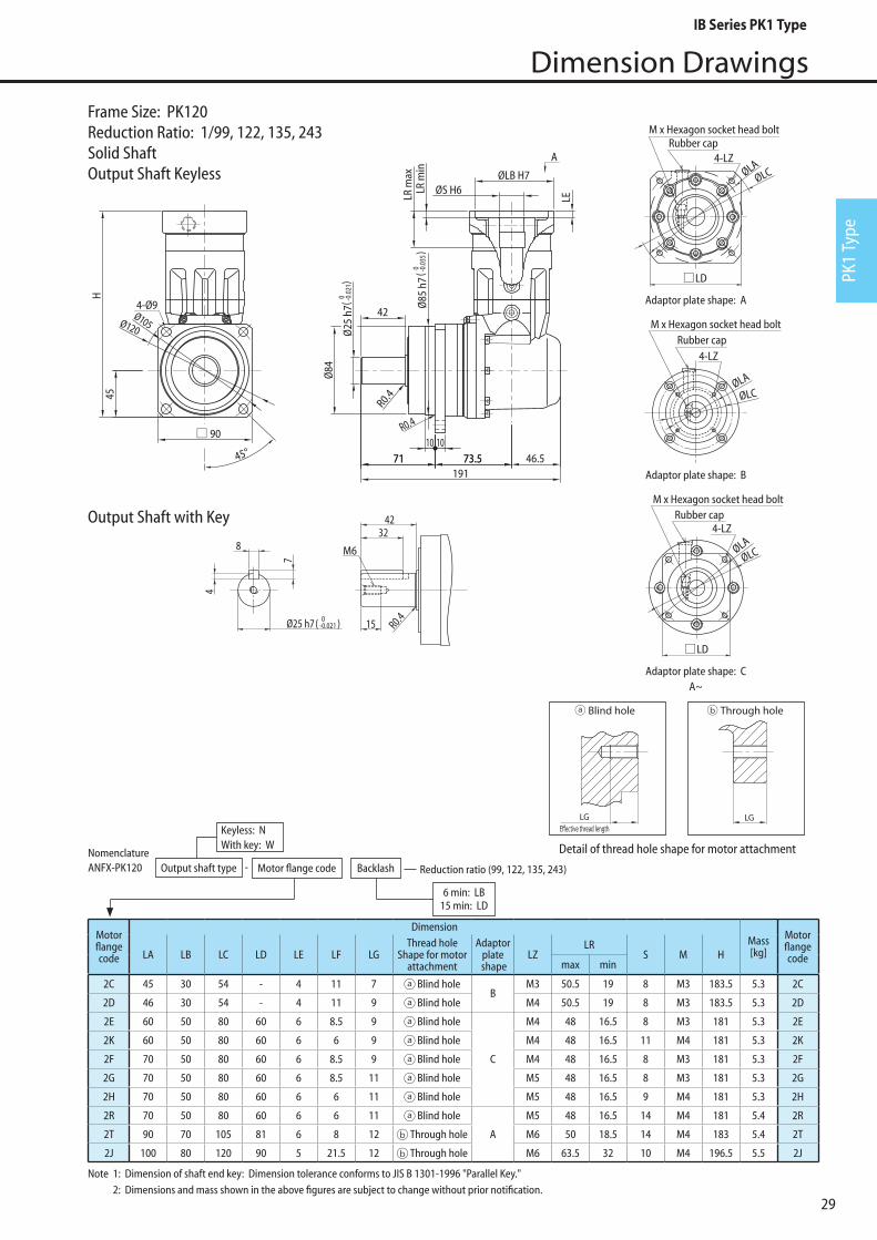
29
Dimension Drawings
PK1
Type
Motorflangecode
DimensionMass[kg]
MotorflangecodeLA LB LC LD LE LF LG
Thread hole Shape for motor
attachment
Adaptorplate
shapeLZ
LRS M H
max min
2C 45 30 54 - 4 11 7 Blind holeB
M3 50.5 19 8 M3 183.5 5.3 2C
2D 46 30 54 - 4 11 9 Blind hole M4 50.5 19 8 M3 183.5 5.3 2D
2E 60 50 80 60 6 8.5 9 Blind hole
C
M4 48 16.5 8 M3 181 5.3 2E
2K 60 50 80 60 6 6 9 Blind hole M4 48 16.5 11 M4 181 5.3 2K
2F 70 50 80 60 6 8.5 9 Blind hole M4 48 16.5 8 M3 181 5.3 2F
2G 70 50 80 60 6 8.5 11 Blind hole M5 48 16.5 8 M3 181 5.3 2G
2H 70 50 80 60 6 6 11 Blind hole M5 48 16.5 9 M4 181 5.3 2H
2R 70 50 80 60 6 6 11 Blind hole
A
M5 48 16.5 14 M4 181 5.4 2R
2T 90 70 105 81 6 8 12 Through hole M6 50 18.5 14 M4 183 5.4 2T
2J 100 80 120 90 5 21.5 12 Through hole M6 63.5 32 10 M4 196.5 5.5 2J
Adaptor plate shape: A
Adaptor plate shape: B
Adaptor plate shape: CA~
73.5 46.5
A
191
45H
ØLB H7ØS H6LR
min
LE
73.571
Ø25
h7 Ø
85 h
7
10 1071
R0.4
Ø84
R0.4
42Ø105Ø120
90
4-Ø9
LR m
ax
45°
M6
4
8
7
Ø25 h7( 0-0.021 )
3242
15 R0.4
( 0 -0.0
21)
( 0 -0.0
35)
Rubber cap4-LZ
M x Hexagon socket head bolt
ØLCØLA
Rubber cap4-LZ
M x Hexagon socket head bolt
M x Hexagon socket head bolt
4-LZRubber cap
ØLCØLA
ØLCØLA
LD
LD
Note 1: Dimension of shaft end key: Dimension tolerance conforms to JIS B 1301-1996 "Parallel Key." 2: Dimensions and mass shown in the above figures are subject to change without prior notification.
NomenclatureANFX-PK120 Motor flange code Backlash Reduction ratio (99, 122, 135, 243)
6 min: LB15 min: LD
Keyless: N With key: W
-Output shaft type
Frame Size: PK120Reduction Ratio: 1/99, 122, 135, 243Solid ShaftOutput Shaft Keyless
Detail of thread hole shape for motor attachment
LGE�ective thread length
Blind hole Through hole With �ange plate
LGE�ective thread length
LGLGE�ective thread length
Blind hole Through hole With �ange plate
LGE�ective thread length
LG
Output Shaft with Key
IB Series PK1 Type

30
Dimension Drawings
4-LZ
M x Hexagon socket head boltRubber cap
ØLAØLC
LD120
Ø135Ø155
4-Ø11
Ø115
h714 13
86.5 55
60
A
Ø114
Ø40
H7
82
121
R0.4
R0.4
262.5
H
LR m
ax
ØLB H7
ØS H6
LR m
in LF
LE
M10
Ø40 h7( 0-0.025 )
8
5
1263
82
R0.422
( 0 -0.03
5)
( 0 -0.0
25)
Adaptor plate shape: AA~
Note 1: Dimension of shaft end key: Dimension tolerance conforms to JIS B 1301-1996 "Parallel Key." 2: Dimension of coupling of motor flange code (0X) includes tolerance (+0.012 ~ +0.023) 3: Dimensions and mass shown in the above figures are subject to change without prior notification.
Motorflangecode
DimensionMass[kg]
MotorflangecodeLA LB LC LD LE LF LG
Thread hole Shape for motor
attachment
Adaptorplate
shapeLZ
LRS M H
max min
1S 145 110 165 120 7 19.5 16 Through hole
A
M8 74 34 22 M6 245 12.3 1S
7Z 145 110 165 120 7 19.5 16 Through hole M8 74 34 24 M6 245 12.3 7Z
1T 145 110 165 120 7 19.5 16 Through hole M8 74 34 28 M6 245 12.3 1T
0Z 135 110 165 120 7 19.5 16 Through hole M8 74 34 28 M6 245 12.3 0Z
0X 200 114.3 230 180 6 41.5 24 Through hole M12 81 60 35 M8 290 14.0 0X*2 *2
NomenclatureANFX-PK130 Motor flange code Backlash Reduction ratio (6)
6 min: LB15 min: LD
Keyless: N With key: W
-Output shaft type
Frame Size: PK130Reduction Ratio: 1/6Solid ShaftOutput Shaft Keyless
Detail of thread hole shape for motor attachment
LGE�ective thread length
Blind hole Through hole With �ange plate
LGE�ective thread length
LG
Output Shaft with Key
IB Series PK1 Type
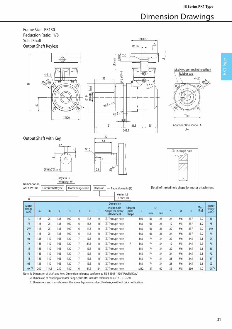
31
Dimension Drawings
PK1
Type
4-LZ
M x Hexagon socket head boltRubber cap
ØLAØLC
LD120
Ø135Ø155
4-Ø11
Ø115
h714 13
86.5 55
60
A
Ø114
Ø40
H7
82
121
R0.4
R0.4
262.5
H
LR m
ax
ØLB H7
ØS H6
LR m
in LF
LE
M10
Ø40 h7( 0-0.025 )
8
5
1263
82
R0.422
( 0 -0.03
5)
( 0 -0.0
25)
Adaptor plate shape: AA~
Note 1: Dimension of shaft end key: Dimension tolerance conforms to JIS B 1301-1996 "Parallel Key." 2: Dimension of coupling of motor flange code (0X) includes tolerance (+0.012 ~ +0.023) 3: Dimensions and mass shown in the above figures are subject to change without prior notification.
Motorflangecode
DimensionMass[kg]
MotorflangecodeLA LB LC LD LE LF LG
Thread hole Shape for motor
attachment
Adaptorplate
shapeLZ
LRS M H
max min
1L 115 95 135 100 6 11.5 16 Through hole
A
M6 66 26 24 M6 237 12.0 1L
7B 115 95 135 100 6 13.5 16 Through hole M8 66 26 19 M5 237 11.9 7B
0W 115 95 135 100 6 11.5 16 Through hole M8 66 26 22 M6 237 12.0 0W
7Y 115 95 135 100 6 11.5 16 Through hole M8 66 26 24 M6 237 12.0 7Y
0Y 135 110 165 120 7 19.5 16 Through hole M8 74 34 22 M6 245 12.3 0Y
7X 145 110 165 120 7 21.5 16 Through hole M8 74 34 19 M5 245 12.2 7X
1S 145 110 165 120 7 19.5 16 Through hole M8 74 34 22 M6 245 12.3 1S
7Z 145 110 165 120 7 19.5 16 Through hole M8 74 34 24 M6 245 12.3 7Z
1T 145 110 165 120 7 19.5 16 Through hole M8 74 34 28 M6 245 12.3 1T
0Z 135 110 165 120 7 19.5 16 Through hole M8 74 34 28 M6 245 12.3 0Z
0X 200 114.3 230 180 6 41.5 24 Through hole M12 81 60 35 M8 290 14.0 0X*2 *2
NomenclatureANFX-PK130 Motor flange code Backlash Reduction ratio (8)
6 min: LB15 min: LD
Keyless: N With key: W
-Output shaft type
Frame Size: PK130Reduction Ratio: 1/8Solid ShaftOutput Shaft Keyless
Detail of thread hole shape for motor attachment
LGE�ective thread length
Blind hole Through hole With �ange plate
LGE�ective thread length
LG
Output Shaft with Key
IB Series PK1 Type

32
Dimension Drawings
Motorflangecode
DimensionMass[kg]
MotorflangecodeLA LB LC LD LE LF LG
Thread hole Shape for motor
attachment
Adaptorplate
shapeLZ
LRS M H
max min
1L 115 95 135 100 6 11.5 16 Through hole
A
M6 66 26 24 M6 237 12.7 1L
7B 115 95 135 100 6 13.5 16 Through hole M8 66 26 19 M5 237 12.6 7B
0W 115 95 135 100 6 11.5 16 Through hole M8 66 26 22 M6 237 12.7 0W
7Y 115 95 135 100 6 11.5 16 Through hole M8 66 26 24 M6 237 12.7 7Y
0Y 135 110 165 120 7 19.5 16 Through hole M8 74 34 22 M6 245 13.1 0Y
7X 145 110 165 120 7 21.5 16 Through hole M8 74 34 19 M5 245 13.0 7X
1S 145 110 165 120 7 19.5 16 Through hole M8 74 34 22 M6 245 13.1 1S
7Z 145 110 165 120 7 19.5 16 Through hole M8 74 34 24 M6 245 13.0 7Z
1T 145 110 165 120 7 19.5 16 Through hole M8 74 34 28 M6 245 12.3 1T
0X 200 114.3 230 180 6 41.5 24 Through hole M8 81 60 35 M8 290 14.0 0X*2 *2
4-LZ
M x Hexagon socket head boltRubber cap
ØLA
ØLC
M10
Ø40 h7( 0-0.025 )
8
5
1263
82
R0.422
LD120
Ø135Ø155
4-Ø11
Ø115
h714 13
86.5 55
60
A
Ø114
Ø40
H7
82
121
R0.4
R0.4
262.5
H
LR m
ax
ØLB H7
ØS H6
LR m
in LF
LE
( 0 -0.03
5)
( 0 -0.0
25)
Adaptor plate shape: AA~
Note 1: Dimension of shaft end key: Dimension tolerance conforms to JIS B 1301-1996 "Parallel Key." 2: Tolerance of coupling for motor flange code "0X" is over tolerance (+0.010~+0.026). 3: Dimensions and mass shown in the above figures are subject to change without prior notification.
NomenclatureANFX-PK130 Motor flange code Backlash Reduction ratio (11, 15)
6 min: LB15 min: LD
Keyless: N With key: W
-Output shaft type
Frame Size: PK130Reduction Ratio: 1/11, 1/15Solid ShaftOutput Shaft Keyless
Detail of thread hole shape for motor attachment
LGE�ective thread length
Blind hole Through hole With �ange plate
LGE�ective thread length
LG
Output Shaft with Key
IB Series PK1 Type
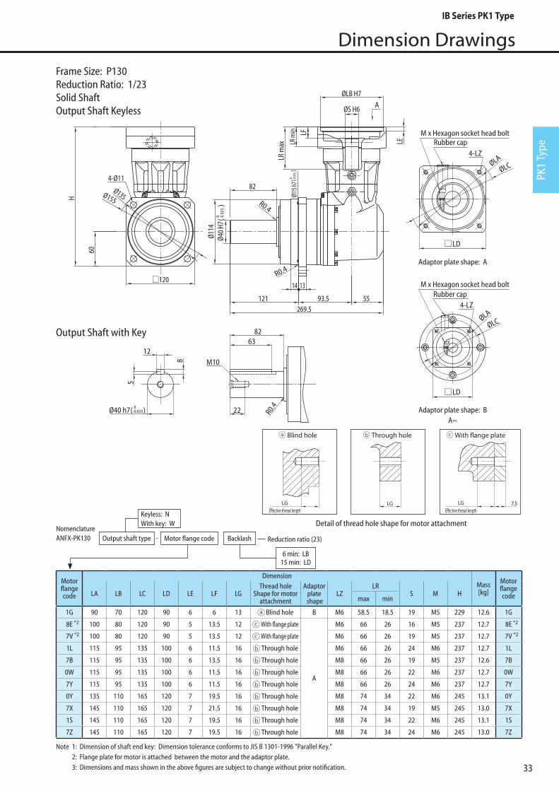
33
Dimension Drawings
PK1
Type
4-LZ
M x Hexagon socket head boltRubber cap
ØLAØLC
269.593.5 55
60
14 13
Ø114
R0.4
121
LD
LD
120
Ø135Ø155
4-Ø11
R0.4
82
A
Ø40
H7
H
LR m
ax
ØLB H7
ØS H6
LR m
in LF
LE
M10
Ø40 h7( 0-0.025)
8
5
1263
82
R0.422
( 0 -0.0
25)
Ø115
h7( 0 -0
.035
)
Adaptor plate shape: A
Adaptor plate shape: BA~
M x Hexagon socket head boltRubber cap
4-LZ
ØLA
ØLC
Motorflangecode
DimensionMass[kg]
MotorflangecodeLA LB LC LD LE LF LG
Thread hole Shape for motor
attachment
Adaptorplate
shapeLZ
LRS M H
max min
1G 90 70 120 90 6 6 13 Blind hole B M6 58.5 18.5 19 M5 229 12.6 1G
8E 100 80 120 90 5 13.5 12 With flange plate
A
M6 66 26 16 M5 237 12.7 8E
7V 100 80 120 90 5 13.5 12 With flange plate M6 66 26 19 M5 237 12.7 7V
1L 115 95 135 100 6 11.5 16 Through hole M6 66 26 24 M6 237 12.7 1L
7B 115 95 135 100 6 13.5 16 Through hole M8 66 26 19 M5 237 12.6 7B
0W 115 95 135 100 6 11.5 16 Through hole M8 66 26 22 M6 237 12.7 0W
7Y 115 95 135 100 6 11.5 16 Through hole M8 66 26 24 M6 237 12.7 7Y
0Y 135 110 165 120 7 19.5 16 Through hole M8 74 34 22 M6 245 13.1 0Y
7X 145 110 165 120 7 21.5 16 Through hole M8 74 34 19 M5 245 13.0 7X
1S 145 110 165 120 7 19.5 16 Through hole M8 74 34 22 M6 245 13.1 1S
7Z 145 110 165 120 7 19.5 16 Through hole M8 74 34 24 M6 245 13.0 7Z
*2 *2
*2 *2
NomenclatureANFX-PK130 Motor flange code Backlash Reduction ratio (23)
6 min: LB15 min: LD
Keyless: N With key: W
-Output shaft type
Frame Size: P130Reduction Ratio: 1/23Solid ShaftOutput Shaft Keyless
Note 1: Dimension of shaft end key: Dimension tolerance conforms to JIS B 1301-1996 "Parallel Key." 2: Flange plate for motor is attached between the motor and the adaptor plate. 3: Dimensions and mass shown in the above figures are subject to change without prior notification.
Detail of thread hole shape for motor attachment
LGE�ective thread length
Blind hole Through hole With �ange plate
LGE�ective thread length
LGLGE�ective thread length
Blind hole Through hole With �ange plate
LGE�ective thread length
LGLGE�ective thread length
Blind hole Through hole With �ange plate
LGE�ective thread length
LG
Output Shaft with Key
IB Series PK1 Type
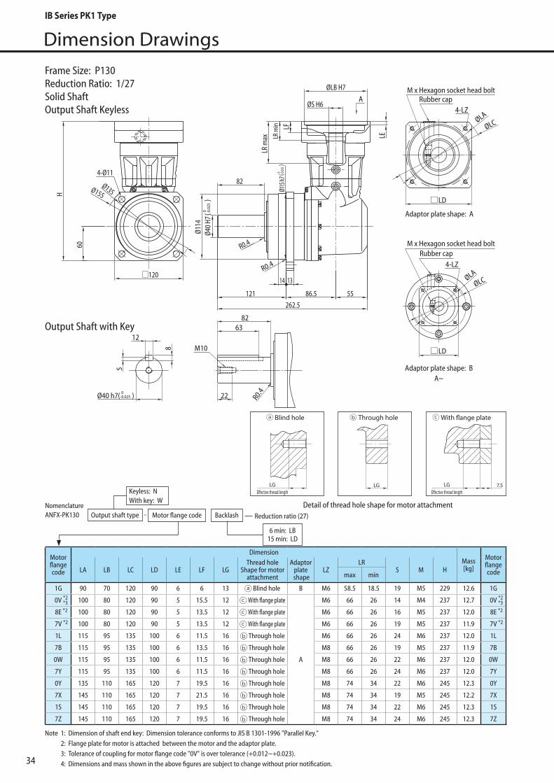
34
Dimension Drawings
4-LZ
M x Hexagon socket head boltRubber cap
ØLA
ØLC
LD
LD
120
Ø135Ø155
4-Ø11
14 13
86.5 55
60
A
Ø114
Ø40
H7
82
121
R0.4
R0.4
262.5
H
LR m
ax
ØLB H7
ØS H6
LR m
in LF
LE
M10
Ø40 h7( 0-0.025 )
8
5
1263
82
R0.422
Ø115
h7( 0 -0
.035
)
( 0 -0.0
25)
Adaptor plate shape: A
M x Hexagon socket head boltRubber cap
4-LZ
ØLAØLC
Adaptor plate shape: BA~
Motorflangecode
DimensionMass[kg]
MotorflangecodeLA LB LC LD LE LF LG
Thread hole Shape for motor
attachment
Adaptorplate
shapeLZ
LRS M H
max min
1G 90 70 120 90 6 6 13 Blind hole B M6 58.5 18.5 19 M5 229 12.6 1G
0V *2*3 100 80 120 90 5 15.5 12 With flange plate
A
M6 66 26 14 M4 237 12.7 0V *2*3
8E 100 80 120 90 5 13.5 12 With flange plate M6 66 26 16 M5 237 12.0 8E
7V 100 80 120 90 5 13.5 12 With flange plate M6 66 26 19 M5 237 11.9 7V
1L 115 95 135 100 6 11.5 16 Through hole M6 66 26 24 M6 237 12.0 1L
7B 115 95 135 100 6 13.5 16 Through hole M8 66 26 19 M5 237 11.9 7B
0W 115 95 135 100 6 11.5 16 Through hole M8 66 26 22 M6 237 12.0 0W
7Y 115 95 135 100 6 11.5 16 Through hole M8 66 26 24 M6 237 12.0 7Y
0Y 135 110 165 120 7 19.5 16 Through hole M8 74 34 22 M6 245 12.3 0Y
7X 145 110 165 120 7 21.5 16 Through hole M8 74 34 19 M5 245 12.2 7X
1S 145 110 165 120 7 19.5 16 Through hole M8 74 34 22 M6 245 12.3 1S
7Z 145 110 165 120 7 19.5 16 Through hole M8 74 34 24 M6 245 12.3 7Z
*2 *2
*2 *2
Frame Size: P130Reduction Ratio: 1/27Solid ShaftOutput Shaft Keyless
NomenclatureANFX-PK130 Motor flange code Backlash Reduction ratio (27)
6 min: LB15 min: LD
Keyless: N With key: W
-Output shaft type
Note 1: Dimension of shaft end key: Dimension tolerance conforms to JIS B 1301-1996 "Parallel Key." 2: Flange plate for motor is attached between the motor and the adaptor plate. 3: Tolerance of coupling for motor flange code "0V" is over tolerance (+0.012~+0.023). 4: Dimensions and mass shown in the above figures are subject to change without prior notification.
Detail of thread hole shape for motor attachment
LGE�ective thread length
Blind hole Through hole With �ange plate
LGE�ective thread length
LGLGE�ective thread length
Blind hole Through hole With �ange plate
LGE�ective thread length
LGLGE�ective thread length
Blind hole Through hole With �ange plate
LGE�ective thread length
LG
Output Shaft with Key
IB Series PK1 Type

35
Dimension Drawings
PK1
Type
M x Hexagon socket head boltRubber cap
4-LZ
4-LZ
M x Hexagon socket head boltRubber cap
ØLA
ØLC
ØLA
ØLC
269.593.5 55
60
14 13
Ø114
R0.4
121
LD
LD
120
Ø135Ø155
4-Ø11
R0.4
82
A
Ø40
H7
H
LR m
ax
ØLB H7
ØS H6
LR m
in LF
LE
M10
Ø40 h7( 0-0.025 )
8
5
1263
82
R0.422
( 0 -0.0
25)
Ø115
h7( 0 -0
.035
)
Adaptor plate shape: A
Adaptor plate shape: BA~
Motorflangecode
DimensionMass[kg]
MotorflangecodeLA LB LC LD LE LF LG
Thread hole Shape for motor
attachment
Adaptorplate
shapeLZ
LRS M H
max min
2R 70 50 80 60 4 5 11 Blind hole
B
M5 55.5 15.5 14 M4 226 12.6 2R
0U 90 70 120 90 6 6 11 Blind hole M5 58.5 18.5 16 M5 229 12.6 0U
7S 90 70 120 90 6 6 11 Blind hole M5 58.5 18.5 19 M5 229 12.6 7S
7P 90 70 120 90 6 6 13 Blind hole M6 58.5 18.5 16 M5 229 12.6 7P
1G 90 70 120 90 6 6 13 Blind hole M6 58.5 18.5 19 M5 229 12.6 1G
2J 100 80 120 90 5 15.5 12 With flange plate
A
M6 66 26 10 M4 237 12.7 2J
0V *2*3 100 80 120 90 5 15.5 12 With flange plate M6 66 26 14 M4 237 12.7 0V *2
*3
8E 100 80 120 90 5 15.5 12 With flange plate M6 66 26 16 M5 237 12.7 8E
7A 115 95 135 100 6 13.5 16 Through hole M8 66 26 16 M5 237 12.7 7A
7R 145 110 165 120 7 21.5 16 Through hole M8 74 34 16 M5 245 13.0 7R
7X 145 110 165 120 7 21.5 16 Through hole M8 74 34 19 M5 245 13.0 7X
7Z 145 110 165 120 7 19.5 16 Through hole M8 74 34 24 M6 245 13.0 7Z
*2 *2
*2 *2
NomenclatureANFX-PK130 Motor flange code Backlash Reduction ratio (33, 45, 50, 63, 68)
6 min: LB15 min: LD
Keyless: N With key: W
-Output shaft type
Frame Size: PK130Reduction Ratio: 1/33, 45, 50, 63, 68Solid ShaftOutput Shaft Keyless
Note 1: Dimension of shaft end key: Dimension tolerance conforms to JIS B 1301-1996 "Parallel Key." 2: Flange plate for motor is attached between the motor and the adaptor plate. 3: Dimension of coupling of motor flange code (0V) includes tolerance (+0.012 ~ +0.023) 4: Dimensions and mass shown in the above figures are subject to change without prior notification.
Detail of thread hole shape for motor attachment
LGE�ective thread length
Blind hole Through hole With �ange plate
LGE�ective thread length
LGLGE�ective thread length
Blind hole Through hole With �ange plate
LGE�ective thread length
LGLGE�ective thread length
Blind hole Through hole With �ange plate
LGE�ective thread length
LG
Output Shaft with Key
IB Series PK1 Type

36
Dimension Drawings
M x Hexagon socket head boltRubber cap
4-LZ
ØLAØLC
269.593.5 55
60
14 13
Ø114
R0.4
121
LD120
Ø135Ø155
4-Ø11
R0.4
82
A
Ø40
H7
H
LR m
ax
ØLB H7
ØS H6
LR m
in LF
LE
M10
Ø40 h7( 0-0.025 )
8
5
1263
82
R0.422
Ø115
h7( 0 -0
.035
)
( 0 -0.0
25)
Adaptor plate shape: AA~
Motorflangecode
DimensionMass[kg]
MotorflangecodeLA LB LC LD LE LF LG
Thread hole Shape for motor
attachment
Adaptorplate
shapeLZ
LRS M H
max min
2L 70 50 80 60 4 5 9 Blind hole
A
M4 55.5 15.5 11 M4 226 12.6 2L
2P 70 50 80 60 4 5 9 Blind hole M4 55.5 15.5 14 M4 226 12.6 2P
2H 70 50 80 60 4 5 11 Blind hole M5 55.5 15.5 9 M4 226 12.6 2H
2R 70 50 80 60 4 5 11 Blind hole M5 55.5 15.5 14 M4 226 12.6 2R
8A 90 70 120 90 6 8 11 Blind hole M5 58.5 18.5 11 M4 229 12.6 8A
8B 90 70 120 90 6 8 11 Blind hole M5 58.5 18.5 14 M4 229 12.6 8B
2T 90 70 120 90 6 8 13 Blind hole M6 58.5 18.5 14 M4 229 12.6 2T
2J 100 80 120 90 5 15.5 12 With flange plate M6 66 26 10 M4 237 12.7 2J
8E 100 80 120 90 5 15.5 12 With flange plate M6 66 26 16 M5 237 12.7 8E
*2 *2
*2 *2
NomenclatureANFX-PK130 Motor flange code Backlash Reduction ratio (99, 122, 135, 243)
6 min: LB15 min: LD
Keyless: N With key: W
-Output shaft type
Frame Size: PK130Reduction Ratio: 1/99, 122, 135, 243Solid ShaftOutput Shaft Keyless
Note 1: Dimension of shaft end key: Dimension tolerance conforms to JIS B 1301-1996 "Parallel Key." 2: Flange plate for motor is attached between the motor and the adaptor plate. 3: Dimensions and mass shown in the above figures are subject to change without prior notification.
Detail of thread hole shape for motor attachment
LGE�ective thread length
Blind hole Through hole With �ange plate
LGE�ective thread length
LGLGE�ective thread length
Blind hole Through hole With �ange plate
LGE�ective thread length
LG
Output Shaft with Key
IB Series PK1 Type
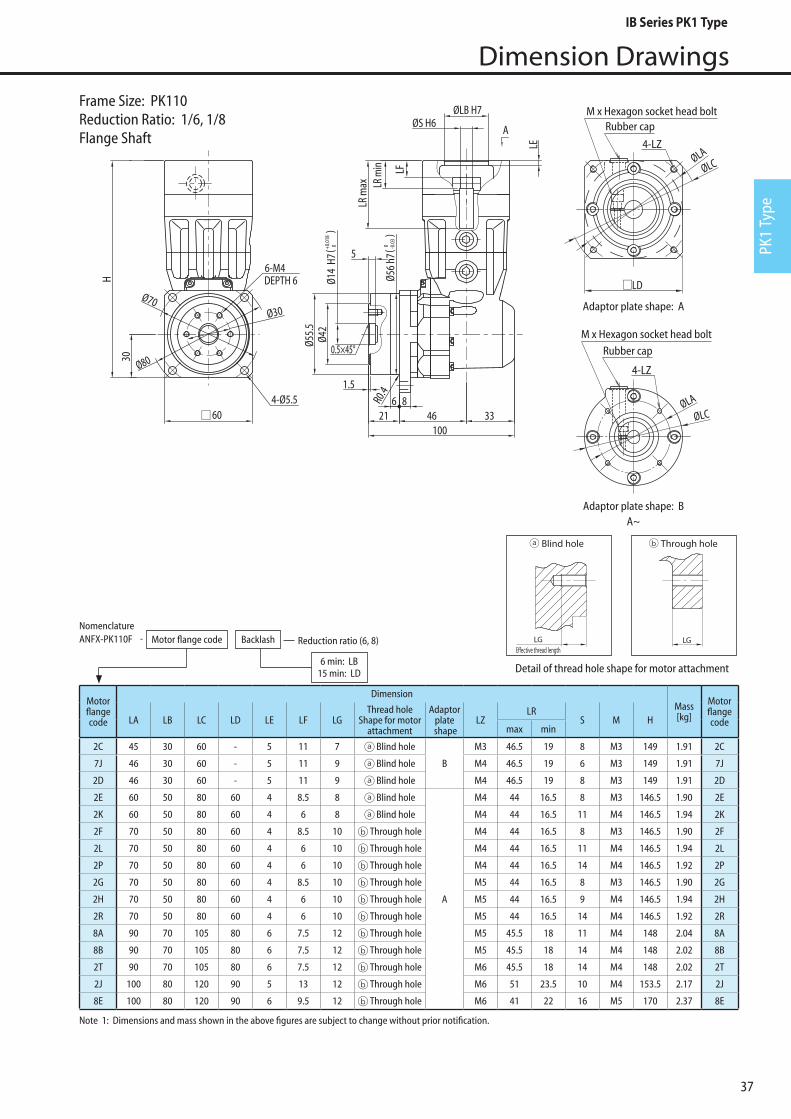
37
Dimension Drawings
PK1
Type
4-LZ
M x Hexagon socket head boltRubber cap
M x Hexagon socket head boltRubber cap
4-LZØLA
ØLC
LD
ØLA
ØLC4-Ø5.5
60
Ø70
Ø80
6-M4DEPTH 6
Ø30
Ø14
H7
Ø42
Ø56
h76 8
21
1.5
46 33100
A
5
0.5×45°Ø55.
5
30
R0.4
LR m
ax
ØLB H7ØS H6
LR m
in LF
LE
H
( 0 -0.0
3)
( 0+0.0
18)
Adaptor plate shape: A
Adaptor plate shape: BA~
Frame Size: PK110Reduction Ratio: 1/6, 1/8Flange Shaft
Note 1: Dimensions and mass shown in the above figures are subject to change without prior notification.
Motorflangecode
DimensionMass[kg]
MotorflangecodeLA LB LC LD LE LF LG
Thread hole Shape for motor
attachment
Adaptorplate
shapeLZ
LRS M H
max min
2C 45 30 60 - 5 11 7 Blind hole
B
M3 46.5 19 8 M3 149 1.91 2C
7J 46 30 60 - 5 11 9 Blind hole M4 46.5 19 6 M3 149 1.91 7J
2D 46 30 60 - 5 11 9 Blind hole M4 46.5 19 8 M3 149 1.91 2D
2E 60 50 80 60 4 8.5 8 Blind hole
A
M4 44 16.5 8 M3 146.5 1.90 2E
2K 60 50 80 60 4 6 8 Blind hole M4 44 16.5 11 M4 146.5 1.94 2K
2F 70 50 80 60 4 8.5 10 Through hole M4 44 16.5 8 M3 146.5 1.90 2F
2L 70 50 80 60 4 6 10 Through hole M4 44 16.5 11 M4 146.5 1.94 2L
2P 70 50 80 60 4 6 10 Through hole M4 44 16.5 14 M4 146.5 1.92 2P
2G 70 50 80 60 4 8.5 10 Through hole M5 44 16.5 8 M3 146.5 1.90 2G
2H 70 50 80 60 4 6 10 Through hole M5 44 16.5 9 M4 146.5 1.94 2H
2R 70 50 80 60 4 6 10 Through hole M5 44 16.5 14 M4 146.5 1.92 2R
8A 90 70 105 80 6 7.5 12 Through hole M5 45.5 18 11 M4 148 2.04 8A
8B 90 70 105 80 6 7.5 12 Through hole M5 45.5 18 14 M4 148 2.02 8B
2T 90 70 105 80 6 7.5 12 Through hole M6 45.5 18 14 M4 148 2.02 2T
2J 100 80 120 90 5 13 12 Through hole M6 51 23.5 10 M4 153.5 2.17 2J
8E 100 80 120 90 6 9.5 12 Through hole M6 41 22 16 M5 170 2.37 8E
NomenclatureANFX-PK110F Motor flange code Backlash Reduction ratio (6, 8)
6 min: LB15 min: LD
-
Detail of thread hole shape for motor attachment
LGE�ective thread length
Blind hole Through hole With �ange plate
LGE�ective thread length
LGLGE�ective thread length
Blind hole Through hole With �ange plate
LGE�ective thread length
LG
IB Series PK1 Type

38
Dimension Drawings
4-LZ
M x Hexagon socket head boltRubber cap
M x Hexagon socket head boltRubber cap
4-LZØLA
ØLC
LD
ØLA
ØLC
4-Ø5.560
Ø70
Ø80
6-M4DEPTH 6
Ø30
Ø14
H7Ø4
2
Ø56
h7
6 821
1.5
46 33100
A
5
0.5×45°
Ø55.
5
30
R0.4
LR m
ax
ØLB H7ØS H6
LR m
in LF
LF
H
( 0+0.0
18)
( 0 -0.0
3)
Adaptor plate shape: A
Adaptor plate shape: BA~
Frame Size: PK110Reduction Ratio: 1/11, 1/15, 1/27Flange Shaft
Note 1: Dimensions and mass shown in the above figures are subject to change without prior notification.
Motorflangecode
DimensionMass[kg]
MotorflangecodeLA LB LC LD LE LF LG
Thread hole Shape for motor
attachment
Adaptorplate
shapeLZ
LRS M H
max min
2C 45 30 60 - 5 11 7 Blind hole
B
M3 46.5 19 8 M3 149 1.91 2C
7J 46 30 60 - 5 11 9 Blind hole M4 46.5 19 6 M3 149 1.91 7J
2D 46 30 60 - 5 11 9 Blind hole M4 46.5 19 8 M3 149 1.91 2D
2E 60 50 80 60 4 8.5 8 Blind hole
A
M4 44 16.5 8 M3 146.5 1.90 2E
2K 60 50 80 60 4 6 8 Blind hole M4 44 16.5 11 M4 146.5 1.94 2K
2F 70 50 80 60 4 8.5 10 Through hole M4 44 16.5 8 M3 146.5 1.90 2F
2L 70 50 80 60 4 6 10 Through hole M4 44 16.5 11 M4 146.5 1.94 2L
2G 70 50 80 60 4 8.5 10 Through hole M5 44 16.5 8 M3 146.5 1.90 2G
2H 70 50 80 60 4 6 10 Through hole M5 44 16.5 9 M4 146.5 1.94 2H
2R 70 50 80 60 4 6 10 Through hole M5 44 16.5 14 M4 146.5 1.92 2R
8A 90 70 105 80 6 7.5 12 Through hole M5 45.5 18 11 M4 148 2.04 8A
8B 90 70 105 80 6 7.5 12 Through hole M5 45.5 18 14 M4 148 2.02 8B
2T 90 70 105 80 6 7.5 12 Through hole M6 45.5 18 14 M4 148 2.02 2T
2J 100 80 120 90 5 13 12 Through hole M6 51 23.5 10 M4 153.5 2.21 2J
8E 100 80 120 90 6 9.5 12 Through hole M6 41 22 16 M5 170 2.37 8E
NomenclatureANFX-PK110F Motor flange code Backlash Reduction ratio (11, 15, 27)
6 min: LB15 min: LD
-
Detail of thread hole shape for motor attachment
LGE�ective thread length
Blind hole Through hole With �ange plate
LGE�ective thread length
LGLGE�ective thread length
Blind hole Through hole With �ange plate
LGE�ective thread length
LG
IB Series PK1 Type
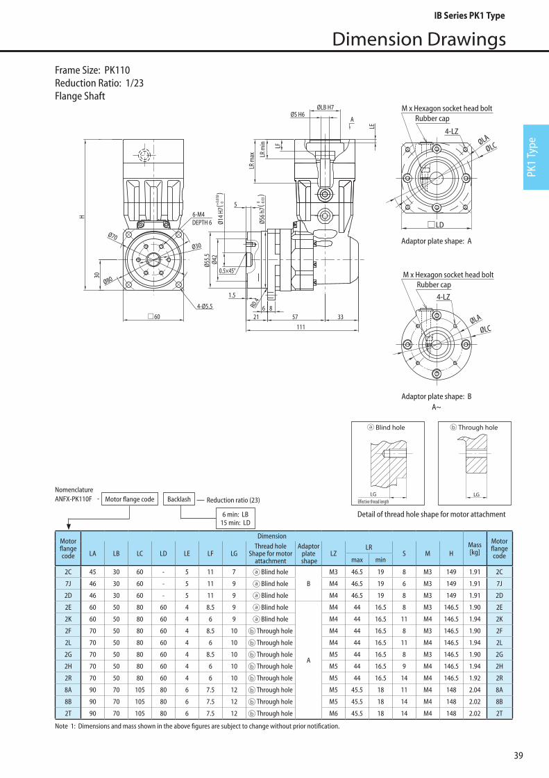
39
Dimension Drawings
PK1
Type
4-LZ
M x Hexagon socket head boltRubber cap
M x Hexagon socket head boltRubber cap
4-LZØLA
ØLC
ØLA
ØLC
LD
4-Ø5.5
60
Ø70
Ø80
6-M4DEPTH 6
Ø30
Ø14
H7Ø4
2
Ø56
h7
6 821
1.5
57 33
111
A
5
0.5×45°
Ø55.
5
30
R0.4
ØLB H7ØS H6
LR m
in LF
LE
H
LR m
ax
( 0+0.0
18)
( 0 -0.0
3)
Adaptor plate shape: A
Adaptor plate shape: BA~
Frame Size: PK110Reduction Ratio: 1/23Flange Shaft
Motorflangecode
DimensionMass[kg]
MotorflangecodeLA LB LC LD LE LF LG
Thread hole Shape for motor
attachment
Adaptorplate
shapeLZ
LRS M H
max min
2C 45 30 60 - 5 11 7 Blind hole
B
M3 46.5 19 8 M3 149 1.91 2C
7J 46 30 60 - 5 11 9 Blind hole M4 46.5 19 6 M3 149 1.91 7J
2D 46 30 60 - 5 11 9 Blind hole M4 46.5 19 8 M3 149 1.91 2D
2E 60 50 80 60 4 8.5 9 Blind hole
A
M4 44 16.5 8 M3 146.5 1.90 2E
2K 60 50 80 60 4 6 9 Blind hole M4 44 16.5 11 M4 146.5 1.94 2K
2F 70 50 80 60 4 8.5 10 Through hole M4 44 16.5 8 M3 146.5 1.90 2F
2L 70 50 80 60 4 6 10 Through hole M4 44 16.5 11 M4 146.5 1.94 2L
2G 70 50 80 60 4 8.5 10 Through hole M5 44 16.5 8 M3 146.5 1.90 2G
2H 70 50 80 60 4 6 10 Through hole M5 44 16.5 9 M4 146.5 1.94 2H
2R 70 50 80 60 4 6 10 Through hole M5 44 16.5 14 M4 146.5 1.92 2R
8A 90 70 105 80 6 7.5 12 Through hole M5 45.5 18 11 M4 148 2.04 8A
8B 90 70 105 80 6 7.5 12 Through hole M5 45.5 18 14 M4 148 2.02 8B
2T 90 70 105 80 6 7.5 12 Through hole M6 45.5 18 14 M4 148 2.02 2T
Note 1: Dimensions and mass shown in the above figures are subject to change without prior notification.
NomenclatureANFX-PK110F Motor flange code Backlash Reduction ratio (23)
6 min: LB15 min: LD
-
Detail of thread hole shape for motor attachment
LGE�ective thread length
Blind hole Through hole With �ange plate
LGE�ective thread length
LGLGE�ective thread length
Blind hole Through hole With �ange plate
LGE�ective thread length
LG
IB Series PK1 Type
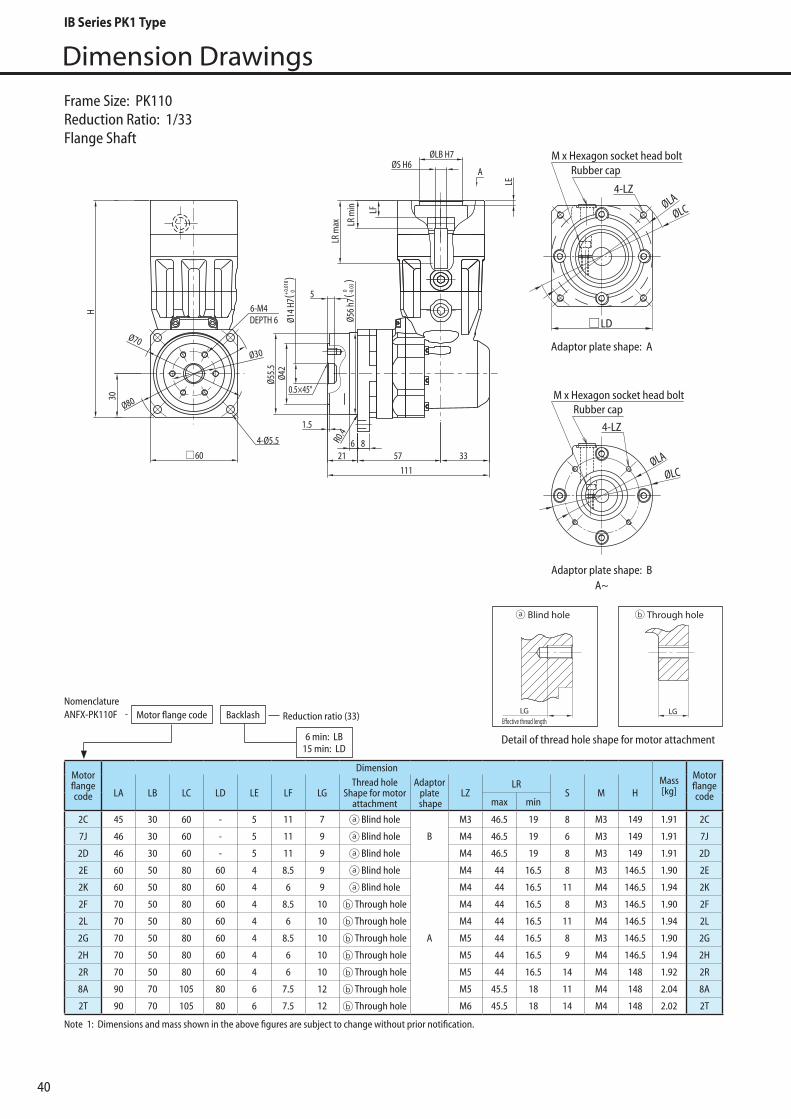
40
Dimension Drawings
4-LZ
M x Hexagon socket head boltRubber cap
M x Hexagon socket head boltRubber cap
4-LZØLA
ØLC
ØLA
ØLC
LD
4-Ø5.5
60
Ø70
Ø80
6-M4DEPTH 6
Ø30
Ø14
H7Ø4
2
Ø56
h7
6 821
1.5
57 33
111
A
5
0.5×45°
Ø55.
5
30
R0.4
ØLB H7ØS H6
LR m
in LF
LE
H
LR m
ax
( 0+0.0
18)
( 0 -0.0
3)
Adaptor plate shape: A
Adaptor plate shape: BA~
Frame Size: PK110Reduction Ratio: 1/33Flange Shaft
Motorflangecode
DimensionMass[kg]
MotorflangecodeLA LB LC LD LE LF LG
Thread hole Shape for motor
attachment
Adaptorplate
shapeLZ
LRS M H
max min
2C 45 30 60 - 5 11 7 Blind hole
B
M3 46.5 19 8 M3 149 1.91 2C
7J 46 30 60 - 5 11 9 Blind hole M4 46.5 19 6 M3 149 1.91 7J
2D 46 30 60 - 5 11 9 Blind hole M4 46.5 19 8 M3 149 1.91 2D
2E 60 50 80 60 4 8.5 9 Blind hole
A
M4 44 16.5 8 M3 146.5 1.90 2E
2K 60 50 80 60 4 6 9 Blind hole M4 44 16.5 11 M4 146.5 1.94 2K
2F 70 50 80 60 4 8.5 10 Through hole M4 44 16.5 8 M3 146.5 1.90 2F
2L 70 50 80 60 4 6 10 Through hole M4 44 16.5 11 M4 146.5 1.94 2L
2G 70 50 80 60 4 8.5 10 Through hole M5 44 16.5 8 M3 146.5 1.90 2G
2H 70 50 80 60 4 6 10 Through hole M5 44 16.5 9 M4 146.5 1.94 2H
2R 70 50 80 60 4 6 10 Through hole M5 44 16.5 14 M4 148 1.92 2R
8A 90 70 105 80 6 7.5 12 Through hole M5 45.5 18 11 M4 148 2.04 8A
2T 90 70 105 80 6 7.5 12 Through hole M6 45.5 18 14 M4 148 2.02 2T
Note 1: Dimensions and mass shown in the above figures are subject to change without prior notification.
NomenclatureANFX-PK110F Motor flange code Backlash Reduction ratio (33)
6 min: LB15 min: LD
-
Detail of thread hole shape for motor attachment
LGE�ective thread length
Blind hole Through hole With �ange plate
LGE�ective thread length
LGLGE�ective thread length
Blind hole Through hole With �ange plate
LGE�ective thread length
LG
IB Series PK1 Type

41
Dimension Drawings
PK1
Type
4-LZ
M x Hexagon socket head boltRubber cap
M x Hexagon socket head boltRubber cap
4-LZØLA
ØLC
ØLA
ØLC
LD
4-Ø5.5
60
Ø70
Ø80
6-M4DEPTH 6
Ø30
Ø14
H7Ø4
2
Ø56
h7
6 821
1.5
57 33
111
A
5
0.5×45°
Ø55.
5
30
R0.4
ØLB H7ØS H6
LR m
in LF
LE
H
LR m
ax
( 0+0.0
18)
( 0 -0.0
3)
Adaptor plate shape: A
Adaptor plate shape: BA~
Frame Size: P110Reduction Ratio: 1/45, 1/50, 1/63, 1/68Flange Shaft
Motorflangecode
DimensionMass[kg]
MotorflangecodeLA LB LC LD LE LF LG
Thread hole Shape for motor
attachment
Adaptorplate
shapeLZ
LRS M H
max min
2C 45 30 60 - 5 11 7 Blind hole
B
M3 46.5 19 8 M3 149 2.16 2C
7J 46 30 60 - 5 11 9 Blind hole M4 46.5 19 6 M3 149 2.16 7J
2D 46 30 60 - 5 11 9 Blind hole M4 46.5 19 8 M3 149 2.16 2D
2E 60 50 80 60 4 8.5 9 Blind hole
A
M4 44 16.5 8 M3 146.5 2.15 2E
2F 70 50 80 60 4 8.5 10 Through hole M4 44 16.5 8 M3 146.5 2.15 2F
2G 70 50 80 60 4 6 10 Through hole M5 44 16.5 8 M3 146.5 2.15 2G
2H 70 50 80 60 4 6 10 Through hole M5 44 16.5 9 M4 146.5 2.19 2H
2R 70 50 80 60 4 6 10 Through hole M5 44 16.5 14 M4 146.5 1.96 2R
2T 90 70 105 80 6 7.5 12 Through hole M6 45.5 18 14 M4 148 2.06 2T
Note 1: Dimensions and mass shown in the above figures are subject to change without prior notification.
NomenclatureANFX-PK110F Motor flange code Backlash Reduction ratio (45, 50, 63, 68)
6 min: LB15 min: LD
-
Detail of thread hole shape for motor attachment
LGE�ective thread length
Blind hole Through hole With �ange plate
LGE�ective thread length
LGLGE�ective thread length
Blind hole Through hole With �ange plate
LGE�ective thread length
LG
IB Series PK1 Type
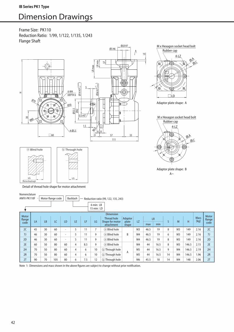
42
Dimension Drawings
4-LZ
M x Hexagon socket head boltRubber cap
M x Hexagon socket head boltRubber cap
4-LZØLA
ØLC
ØLA
ØLC
LD
4-Ø5.5
60
Ø70
Ø80
6-M4DEPTH 6
Ø30
Ø14
H7Ø4
2
Ø56
h7
6 821
1.5
57 33
111
A
5
0.5×45°
Ø55.
5
30
R0.4
ØLB H7ØS H6
LR m
in LF
LE
H
LR m
ax
( 0+0.0
18)
( 0 -0.0
3)
Adaptor plate shape: A
Adaptor plate shape: BA~
Frame Size: PK110Reduction Ratio: 1/99, 1/122, 1/135, 1/243Flange Shaft
Motorflangecode
DimensionMass[kg]
MotorflangecodeLA LB LC LD LE LF LG
Thread hole Shape for motor
attachment
Adaptorplate
shapeLZ
LRS M H
max min
2C 45 30 60 - 5 11 7 Blind hole
B
M3 46.5 19 8 M3 149 2.16 2C
7J 46 30 60 - 5 11 9 Blind hole M4 46.5 19 6 M3 149 2.16 7J
2D 46 30 60 - 5 11 9 Blind hole M4 46.5 19 8 M3 149 2.16 2D
2E 60 50 80 60 4 8.5 9 Blind hole
A
M4 44 16.5 8 M3 146.5 2.15 2E
2H 70 50 80 60 4 6 10 Through hole M5 44 16.5 9 M4 146.5 2.19 2H
2R 70 50 80 60 4 6 10 Through hole M5 44 16.5 14 M4 146.5 1.96 2R
2T 90 70 105 80 6 7.5 12 Through hole M6 45.5 18 14 M4 148 2.06 2T
Note 1: Dimensions and mass shown in the above figures are subject to change without prior notification.
NomenclatureANFX-PK110F Motor flange code Backlash Reduction ratio (99, 122, 135, 243)
6 min: LB15 min: LD
-
Detail of thread hole shape for motor attachment
LGE�ective thread length
Blind hole Through hole With �ange plate
LGE�ective thread length
LGLGE�ective thread length
Blind hole Through hole With �ange plate
LGE�ective thread length
LG
IB Series PK1 Type

43
Dimension Drawings
PK1
Type
Ø105Ø120
90
4-Ø9 DEPTH 96-M6
45H
Ø24
H7
Ø65
10 1027
1.5
68 46.5141.5
Ø45
60°
LR m
axLR
min
0.5×45°Ø8
5 H7
5Ø8
4
R0.4
A
ØLB H7ØS H6
LE
( 0+0.0
21) ( 0 -0
.035
)
Adaptor plate shape: AA~
Rubber cap4-LZ
M x Hexagon socket head bolt
ØLCØLA
LD
Note 1: Tolerance of coupling for motor flange code "0V" is over tolerance (+0.012~+0.023). 2: Dimensions and mass shown in the above figures are subject to change without prior notification.
Motorflangecode
DimensionMass[kg]
MotorflangecodeLA LB LC LD LE LF LG
Thread hole Shape for motor
attachment
Adaptorplate
shapeLZ
LRS M H
max min
0U 90 70 105 81 6 6 12 Through hole
A
M5 50 18.5 16 M5 183 4.9 0U
7S 90 70 105 81 6 6 12 Through hole M5 50 18.5 19 M5 183 4.8 7S
7P 90 70 105 81 6 6 12 Through hole M6 50 18.5 16 M5 183 4.9 7P
1G 90 70 105 81 6 6 12 Through hole M6 50 18.5 19 M5 183 4.8 1G
0V 100 80 120 90 5 21.5 12 Through hole M6 63.5 32 14 M4 196.5 5.0 0V
8E 100 80 120 90 5 19.5 12 Through hole M6 63.5 32 16 M5 196.5 5.0 8E
7V 100 80 120 90 5 19.5 12 Through hole M6 63.5 32 19 M5 196.5 4.9 7V
1L 115 95 135 100 6 17 16 Through hole M6 46 31.5 24 M6 209.5 5.3 1L
7A 115 95 135 100 6 19.5 16 Through hole M8 63.5 32 16 M5 196.5 5.1 7A
7B 115 95 135 100 6 19.5 16 Through hole M8 63.5 32 19 M5 196.5 5.0 7B
0W 115 95 135 100 6 17 16 Through hole M8 46 31.5 22 M6 209.5 5.4 0W
7Y 115 95 135 100 6 17 16 Through hole M8 46 31.5 24 M6 209.5 5.3 7Y
0Y 135 110 165 120 7 17 16 Through hole M8 46 31.5 22 M6 209.5 5.5 0Y
7R 145 110 165 120 7 22.5 16 Through hole M8 66.5 35 16 M5 199.5 5.2 7R
7X 145 110 165 120 7 22.5 16 Through hole M8 66.5 35 19 M5 199.5 5.2 7X
1S 145 110 165 120 7 42 16 Through hole M8 71 56.5 22 M6 234.5 5.7 1S
7Z 145 110 165 120 7 42 16 Through hole M8 71 56.5 24 M6 234.5 5.6 7Z
*1 *1
NomenclatureANFX-PK120F Motor flange code Backlash Reduction ratio (6)
6 min: LB15 min: LD
-
Frame Size: PK120Reduction Ratio: 1/6Flange Shaft
Detail of thread hole shape for motor attachment
LGE�ective thread length
Blind hole Through hole With �ange plate
LGE�ective thread length
LG
IB Series PK1 Type
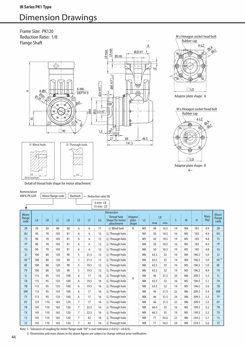
44
Dimension Drawings
Ø105Ø120
90
4-Ø9 DEPTH 96-M6
45H
Ø24
H7
Ø65
10 1027
1.5
68 46.5141.5
Ø45
60°
LR m
axLR
min
0.5×45°Ø8
5 H7
5Ø8
4
R0.4
A
ØLB H7ØS H6
LE
( 0+0.0
21) ( 0 -0
.035
)
Adaptor plate shape: A
Adaptor plate shape: BA~
4-LZ
M x Hexagon socket head boltRubber cap
Rubber cap4-LZ
M x Hexagon socket head bolt
ØLCØLA
ØLA
ØLC
LD
LD
Frame Size: PK120Reduction Ratio: 1/8Flange Shaft
Note 1: Tolerance of coupling for motor flange code "0V" is over tolerance (+0.012~+0.023). 2: Dimensions and mass shown in the above figures are subject to change without prior notification.
Motorflangecode
DimensionMass[kg]
MotorflangecodeLA LB LC LD LE LF LG
Thread hole Shape for motor
attachment
Adaptorplate
shapeLZ
LRS M H
max min
2R 70 50 80 60 6 6 11 Blind hole B M5 48 16.5 14 M4 181 4.9 2R
0U 90 70 105 81 6 6 12 Through hole
A
M5 50 18.5 16 M5 183 4.9 0U
7S 90 70 105 81 6 6 12 Through hole M5 50 18.5 19 M5 183 4.8 7S
7P 90 70 105 81 6 6 12 Through hole M6 50 18.5 16 M5 183 4.9 7P
1G 90 70 105 81 6 6 12 Through hole M6 50 18.5 19 M5 183 4.8 1G
2J 100 80 120 90 5 21.5 12 Through hole M6 63.5 32 10 M4 196.5 5.0 2J
0V 100 80 120 90 5 21.5 12 Through hole M6 63.5 32 14 M4 196.5 5.0 0V
8E 100 80 120 90 5 19.5 12 Through hole M6 63.5 32 16 M5 196.5 5.0 8E
7V 100 80 120 90 5 19.5 12 Through hole M6 63.5 32 19 M5 196.5 4.9 7V
1L 115 95 135 100 6 17 16 Through hole M6 46 31.5 24 M6 209.5 5.3 1L
7A 115 95 135 100 6 19.5 16 Through hole M8 63.5 32 16 M5 196.5 5.1 7A
7B 115 95 135 100 6 19.5 16 Through hole M8 63.5 32 19 M5 196.5 5.0 7B
0W 115 95 135 100 6 17 16 Through hole M8 46 31.5 22 M6 209.5 5.4 0W
7Y 115 95 135 100 6 17 16 Through hole M8 46 31.5 24 M6 209.5 5.3 7Y
0Y 135 110 165 120 7 17 16 Through hole M8 46 31.5 22 M6 209.5 5.5 0Y
7R 145 110 165 120 7 22.5 16 Through hole M8 66.5 35 16 M5 199.5 5.2 7R
7X 145 110 165 120 7 22.5 16 Through hole M8 66.5 35 19 M5 199.5 5.2 7X
1S 145 110 165 120 7 42 16 Through hole M8 71 56.5 22 M6 234.5 5.7 1S
7Z 145 110 165 120 7 42 16 Through hole M8 71 56.5 24 M6 234.5 5.6 7Z
*1 *1
NomenclatureANFX-PK120F Motor flange code Backlash Reduction ratio (8)
6 min: LB15 min: LD
-
Detail of thread hole shape for motor attachment
LGE�ective thread length
Blind hole Through hole With �ange plate
LGE�ective thread length
LGLGE�ective thread length
Blind hole Through hole With �ange plate
LGE�ective thread length
LG
IB Series PK1 Type

45
Dimension Drawings
PK1
Type
Adaptor plate shape: A
Adaptor plate shape: BA~
4-LZRubber cap
M x Hexagon socket head bolt
Rubber cap4-LZ
M x Hexagon socket head bolt
ØLCØLA
ØLCØLA
Ø105Ø120
LD
LD
90
4-Ø9 DEPTH 96-M6
45H
Ø24
H7
Ø65
10 1027
1.5
68 46.5141.5
Ø45
60°
LR m
axLR
min
0.5×45°
Ø85
H7
5Ø8
4
R0.4
A
ØLB H7ØS H6
LE
( 0+0.0
21) ( 0 -0
.035
)
Note 1: Tolerance of coupling for motor flange code "0V" is over tolerance (+0.012~+0.023). 2: Dimensions and mass shown in the above figures are subject to change without prior notification.
Motorflangecode
DimensionMass[kg]
MotorflangecodeLA LB LC LD LE LF LG
Thread hole Shape for motor
attachment
Adaptorplate
shapeLZ
LRS M H
max min
2P 70 50 80 60 6 6 9 Blind holeB
M4 48 16.5 14 M4 181 5.2 2P
2R 70 50 80 60 6 6 11 Blind hole M5 48 16.5 14 M4 181 5.2 2R
8B 90 70 105 81 6 8 12 Through hole
A
M5 50 18.5 14 M4 183 5.2 8B
0U 90 70 105 81 6 6 12 Through hole M5 50 18.5 16 M5 183 5.2 0U
7S 90 70 105 81 6 6 12 Through hole M5 50 18.5 19 M5 183 5.2 7S
2T 90 70 105 81 6 8 12 Through hole M6 50 18.5 14 M4 183 5.2 2T
7P 90 70 105 81 6 6 12 Through hole M6 50 18.5 16 M5 183 5.2 7P
1G 90 70 105 81 6 6 12 Through hole M6 50 18.5 19 M5 183 5.2 1G
2J 100 80 120 90 5 21.5 12 Through hole M6 63.5 32 10 M4 196.5 5.3 2J
0V 100 80 120 90 5 21.5 12 Through hole M6 63.5 32 14 M4 196.5 5.3 0V
8E 100 80 120 90 5 19.5 12 Through hole M6 63.5 32 16 M5 196.5 5.3 8E
7V 100 80 120 90 5 19.5 12 Through hole M6 63.5 32 19 M5 196.5 5.3 7V
1L 115 95 135 100 6 17 16 Through hole M6 46 31.5 24 M6 209.5 5.7 1L
7A 115 95 135 100 6 19.5 16 Through hole M8 63.5 32 16 M5 196.5 5.4 7A
0W 115 95 135 100 6 17 16 Through hole M8 46 31.5 22 M6 209.5 5.7 0W
7Y 115 95 135 100 6 17 16 Through hole M8 46 31.5 24 M6 209.5 5.7 7Y
0Y 135 110 165 120 7 17 16 Through hole M8 46 31.5 22 M6 209.5 5.8 0Y
7R 145 110 165 120 7 22.5 16 Through hole M8 66.5 35 16 M5 199.5 5.5 7R
7X 145 110 165 120 7 22.5 16 Through hole M8 66.5 35 19 M5 199.5 5.5 7X
7Z 145 110 165 120 7 42 16 Through hole M8 71 56.5 24 M6 234.5 6.0 7Z
*1 *1
NomenclatureANFX-PK120F Motor flange code Backlash Reduction ratio (11, 15)
6 min: LB15 min: LD
-
Frame Size: PK120Reduction Ratio: 1/11, 1/15Flange Shaft
Detail of thread hole shape for motor attachment
LGE�ective thread length
Blind hole Through hole With �ange plate
LGE�ective thread length
LGLGE�ective thread length
Blind hole Through hole With �ange plate
LGE�ective thread length
LG
IB Series PK1 Type

46
Dimension Drawings
Frame Size: PK120Reduction Ratio: 1/23Flange Shaft
4-LZRubber cap
M x Hexagon socket head bolt
Rubber cap
4-LZ
M x Hexagon socket head bolt
ØLCØLA
ØLCØLA
Ø105Ø120
LD
LD
90
4-Ø9DEPTH 96-M6
45H
Ø24
H7
Ø65
10 1027
1.5
73.5 46.5147
Ø45
60°
LR m
axLR
min
0.5×45°Ø8
5 H7
5
Ø84
R0.4
A
ØLB H7ØS H6
LE
( 0+0.0
21) ( 0 -0
.035
)
Adaptor plate shape: A
Adaptor plate shape: BA~
Note 1: Tolerance of coupling for motor flange code "0V" is over tolerance (+0.012~+0.023). 2: Dimensions and mass shown in the above figures are subject to change without prior notification.
Motorflangecode
DimensionMass[kg]
MotorflangecodeLA LB LC LD LE LF LG
Thread hole Shape for motor
attachment
Adaptorplate
shapeLZ
LRS M H
max min
2P 70 50 80 60 6 6 9 Blind hole
B
M4 48 16.5 14 M4 181 5.2 2P
2H 70 50 80 60 6 6 11 Blind hole M5 48 16.5 9 M4 181 5.2 2H
2R 70 50 80 60 6 6 11 Blind hole M5 48 16.5 14 M4 181 5.2 2R
8B 90 70 105 81 6 8 12 Through hole
A
M5 50 18.5 14 M4 183 5.2 8B
0U 90 70 105 81 6 6 12 Through hole M5 50 18.5 16 M5 183 5.2 0U
7S 90 70 105 81 6 6 12 Through hole M5 50 18.5 19 M5 183 5.2 7S
2T 90 70 105 81 6 8 12 Through hole M6 50 18.5 14 M4 183 5.2 2T
7P 90 70 105 81 6 6 12 Through hole M6 50 18.5 16 M5 183 5.2 7P
1G 90 70 105 81 6 6 12 Through hole M6 50 18.5 19 M5 183 5.2 1G
2J 100 80 120 90 5 21.5 12 Through hole M6 63.5 32 10 M4 196.5 5.3 2J
0V 100 80 120 90 5 21.5 12 Through hole M6 63.5 32 14 M4 196.5 5.3 0V
8E 100 80 120 90 5 19.5 12 Through hole M6 63.5 32 16 M5 196.5 5.3 8E
7A 115 95 135 100 6 19.5 16 Through hole M8 63.5 32 16 M5 196.5 5.4 7A
7R 145 110 165 120 7 22.5 16 Through hole M8 66.5 35 16 M5 199.5 5.5 7R
7X 145 110 165 120 7 22.5 16 Through hole M8 66.5 35 19 M5 199.5 5.5 7X
7Z 145 110 165 120 7 42 16 Through hole M8 71 56.5 24 M6 234.5 6.0 7Z
*1 *1
NomenclatureANFX-PK120F Motor flange code Backlash Reduction ratio (23)
6 min: LB15 min: LD
-
Detail of thread hole shape for motor attachment
LGE�ective thread length
Blind hole Through hole With �ange plate
LGE�ective thread length
LGLGE�ective thread length
Blind hole Through hole With �ange plate
LGE�ective thread length
LG
IB Series PK1 Type
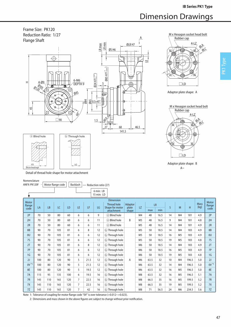
47
Dimension Drawings
PK1
Type
Adaptor plate shape: A
Adaptor plate shape: BA~
4-LZRubber cap
M x Hexagon socket head bolt
Rubber cap
4-LZ
M x Hexagon socket head bolt
ØLCØLA
ØLCØLA
LD
LD
Ø105Ø120
90
4-Ø9 DEPTH 96-M6
45H
Ø24
H7
Ø65
10 1027
1.5
68 46.5141.5
Ø45
60°
LR m
axLR
min
0.5×45°Ø8
5 H7
5Ø8
4
R0.4
A
ØLB H7
ØS H6
LE
( 0+0.0
21) ( 0 -0
.035
)
Note 1: Tolerance of coupling for motor flange code "0V" is over tolerance (+0.012~+0.023). 2: Dimensions and mass shown in the above figures are subject to change without prior notification.
Motorflangecode
DimensionMass[kg]
MotorflangecodeLA LB LC LD LE LF LG
Thread hole Shape for motor
attachment
Adaptorplate
shapeLZ
LRS M H
max min
2P 70 50 80 60 6 6 9 Blind hole
B
M4 48 16.5 14 M4 181 4.9 2P
2H 70 50 80 60 6 6 11 Blind hole M5 48 16.5 9 M4 181 4.8 2H
2R 70 50 80 60 6 6 11 Blind hole M5 48 16.5 14 M4 181 4.9 2R
8B 90 70 105 81 6 8 12 Through hole
A
M5 50 18.5 14 M4 183 4.9 8B
0U 90 70 105 81 6 6 12 Through hole M5 50 18.5 16 M5 183 4.9 0U
7S 90 70 105 81 6 6 12 Through hole M5 50 18.5 19 M5 183 4.8 7S
2T 90 70 105 81 6 8 12 Through hole M6 50 18.5 14 M4 183 4.9 2T
7P 90 70 105 81 6 6 12 Through hole M6 50 18.5 16 M5 183 4.9 7P
1G 90 70 105 81 6 6 12 Through hole M6 50 18.5 19 M5 183 4.8 1G
2J 100 80 120 90 5 21.5 12 Through hole M6 63.5 32 10 M4 196.5 5.0 2J
0V 100 80 120 90 5 21.5 12 Through hole M6 63.5 32 14 M4 196.5 5.0 0V
8E 100 80 120 90 5 19.5 12 Through hole M6 63.5 32 16 M5 196.5 5.0 8E
7A 115 95 135 100 6 19.5 16 Through hole M8 63.5 32 16 M5 196.5 5.1 7A
7R 145 110 165 120 7 22.5 16 Through hole M8 66.5 35 16 M5 199.5 5.2 7R
7X 145 110 165 120 7 22.5 16 Through hole M8 66.5 35 19 M5 199.5 5.2 7X
7Z 145 110 165 120 7 42 16 Through hole M8 71 56.5 24 M6 234.5 5.6 7Z
*1 *1
NomenclatureANFX-PK120F Motor flange code Backlash Reduction ratio (27)
6 min: LB15 min: LD
-
Frame Size: PK120Reduction Ratio: 1/27Flange Shaft
Detail of thread hole shape for motor attachment
LGE�ective thread length
Blind hole Through hole With �ange plate
LGE�ective thread length
LGLGE�ective thread length
Blind hole Through hole With �ange plate
LGE�ective thread length
LG
IB Series PK1 Type
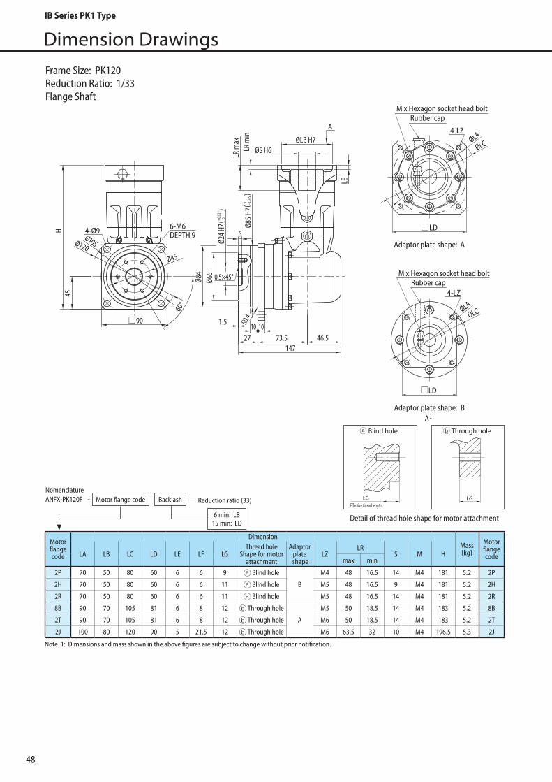
48
Dimension Drawings
Adaptor plate shape: A
Adaptor plate shape: BA~
4-LZRubber cap
M x Hexagon socket head bolt
Rubber cap
4-LZ
M x Hexagon socket head bolt
ØLCØLA
ØLCØLA
Ø105Ø120
LD
LD
90
4-Ø9 DEPTH 96-M6
45H
Ø24
H7
Ø65
10 1027
1.5
73.5 46.5147
Ø45
60°
LR m
axLR
min
0.5×45°
Ø85
H7
5
Ø84
R0.4
A
ØLB H7ØS H6
LE
( 0+0.0
21) ( 0 -0
.035
)
Motorflangecode
DimensionMass[kg]
MotorflangecodeLA LB LC LD LE LF LG
Thread hole Shape for motor
attachment
Adaptorplate
shapeLZ
LRS M H
max min
2P 70 50 80 60 6 6 9 Blind hole
B
M4 48 16.5 14 M4 181 5.2 2P
2H 70 50 80 60 6 6 11 Blind hole M5 48 16.5 9 M4 181 5.2 2H
2R 70 50 80 60 6 6 11 Blind hole M5 48 16.5 14 M4 181 5.2 2R
8B 90 70 105 81 6 8 12 Through hole
A
M5 50 18.5 14 M4 183 5.2 8B
2T 90 70 105 81 6 8 12 Through hole M6 50 18.5 14 M4 183 5.2 2T
2J 100 80 120 90 5 21.5 12 Through hole M6 63.5 32 10 M4 196.5 5.3 2J
Note 1: Dimensions and mass shown in the above figures are subject to change without prior notification.
NomenclatureANFX-PK120F Motor flange code Backlash Reduction ratio (33)
6 min: LB15 min: LD
-
Frame Size: PK120Reduction Ratio: 1/33Flange Shaft
Detail of thread hole shape for motor attachment
LGE�ective thread length
Blind hole Through hole With �ange plate
LGE�ective thread length
LGLGE�ective thread length
Blind hole Through hole With �ange plate
LGE�ective thread length
LG
IB Series PK1 Type

49
Dimension Drawings
PK1
Type
Adaptor plate shape: A
Adaptor plate shape: BA~
4-LZRubber cap
M x Hexagon socket head bolt
Rubber cap
4-LZ
M x Hexagon socket head bolt
ØLCØLA
ØLCØLA
Ø105Ø120
LD
LD
90
4-Ø9 DEPTH 96-M6
45H
Ø24
H7
Ø65
10 1027
1.5
73.5 46.5147
Ø45
60°
LR m
axLR
min
0.5×45°
Ø85
H7
5
Ø84
R0.4
A
ØLB H7ØS H6
LE
( 0+0.0
21) ( 0 -0
.035
)
Motorflangecode
DimensionMass[kg]
MotorflangecodeLA LB LC LD LE LF LG
Thread hole Shape for motor
attachment
Adaptorplate
shapeLZ
LRS M H
max min
2K 60 50 80 60 6 6 9 Blind hole
B
M4 48 16.5 11 M4 181 5.2 2K
2L 70 50 80 60 6 6 9 Blind hole M4 48 16.5 11 M4 181 5.2 2L
2P 70 50 80 60 6 6 9 Blind hole M4 48 16.5 14 M4 181 5.2 2P
2H 70 50 80 60 6 6 11 Blind hole M5 48 16.5 9 M4 181 5.2 2H
2R 70 50 80 60 6 6 11 Blind hole M5 48 16.5 14 M4 181 5.2 2R
8A 90 70 105 81 6 8 12 Through hole
A
M5 50 18.5 11 M4 183 5.2 8A
8B 90 70 105 81 6 8 12 Through hole M5 50 18.5 14 M4 183 5.2 8B
2T 90 70 105 81 6 8 12 Through hole M6 50 18.5 14 M4 183 5.2 2T
2J 100 80 120 90 5 21.5 12 Through hole M6 63.5 32 10 M4 196.5 5.3 2J
Note 1: Dimensions and mass shown in the above figures are subject to change without prior notification.
NomenclatureANFX-PK120F Motor flange code Backlash Reduction ratio (45, 50, 63, 68)
6 min: LB15 min: LD
-
Frame Size: PK120Reduction Ratio: 1/45, 50, 63, 68Flange Shaft
Detail of thread hole shape for motor attachment
LGE�ective thread length
Blind hole Through hole With �ange plate
LGE�ective thread length
LGLGE�ective thread length
Blind hole Through hole With �ange plate
LGE�ective thread length
LG
IB Series PK1 Type

50
Dimension Drawings
Motorflangecode
DimensionMass[kg]
MotorflangecodeLA LB LC LD LE LF LG
Thread hole Shape for motor
attachment
Adaptorplate
shapeLZ
LRS M H
max min
2C 45 30 54 - 4 11 7 Blind holeB
M3 50.5 19 8 M3 183.5 5.1 2C
2D 46 30 54 - 4 11 9 Blind hole M4 50.5 19 8 M3 183.5 5.1 2D
2E 60 50 80 60 6 8.5 9 Blind hole
C
M4 48 16.5 8 M3 181 5.1 2E
2K 60 50 80 60 6 6 9 Blind hole M4 48 16.5 11 M4 181 5.2 2K
2F 70 50 80 60 6 8.5 9 Blind hole M4 48 16.5 8 M3 181 5.1 2F
2G 70 50 80 60 6 8.5 11 Blind hole M5 48 16.5 8 M3 181 5.1 2G
2H 70 50 80 60 6 6 11 Blind hole M5 48 16.5 9 M4 181 5.2 2H
2R 70 50 80 60 6 6 11 Blind hole
A
M5 48 16.5 14 M4 181 5.2 2R
2T 90 70 105 81 6 8 12 Through hole M6 50 18.5 14 M4 183 5.2 2T
2J 100 80 120 90 5 21.5 12 Through hole M6 63.5 32 10 M4 196.5 5.5 2J
Adaptor plate shape: A
Adaptor plate shape: B
Adaptor plate shape: CA~
Rubber cap4-LZ
M x Hexagon socket head bolt
ØLCØLA
Rubber cap4-LZ
M x Hexagon socket head bolt
M x Hexagon socket head bolt
4-LZRubber cap
ØLCØLA
ØLCØLA
Ø105Ø120
LD
LD
90
4-Ø9 DEPTH 96-M6
45H
Ø24
H7
Ø65
10 1027
1.5
73.5 46.5147
Ø45
60°
LR m
axLR
min
0.5×45°
Ø85
H75
Ø84
R0.4
A
ØLB H7
ØS H6
LE
( 0+0.0
21) ( 0 -0
.035
)
Note 1: Dimensions and mass shown in the above figures are subject to change without prior notification.
NomenclatureANFX-PK120F Motor flange code Backlash Reduction ratio (99, 122, 135, 243)
6 min: LB15 min: LD
-
Frame Size: PK120Reduction Ratio: 1/99, 122, 135, 243Flange Shaft
Detail of thread hole shape for motor attachment
LGE�ective thread length
Blind hole Through hole With �ange plate
LGE�ective thread length
LGLGE�ective thread length
Blind hole Through hole With �ange plate
LGE�ective thread length
LG
IB Series PK1 Type
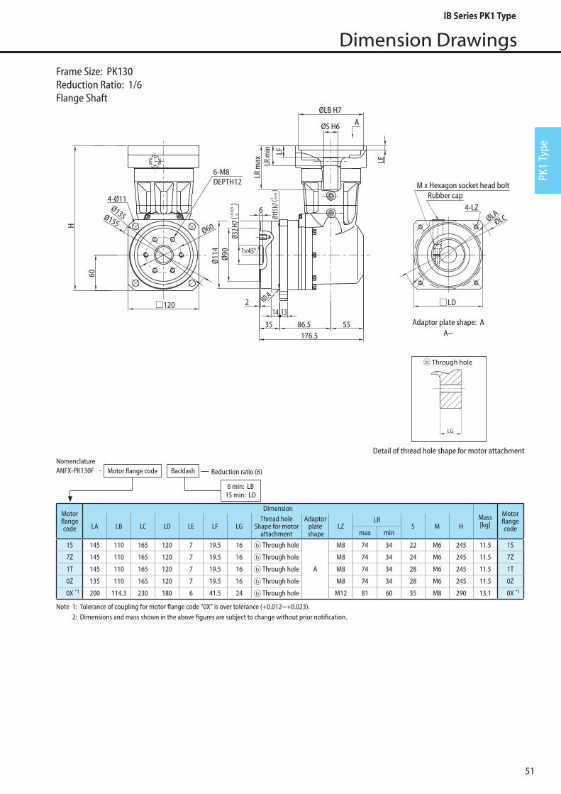
51
Dimension Drawings
PK1
Type
4-LZ
M x Hexagon socket head boltRubber cap
ØLAØLC
LD120
Ø60
Ø135Ø155
6-M8DEPTH12
4-Ø11
Ø32 H
7Ø
90
176.535
14 132
86.5 55
60
A
6Ø
114 1×45°
R0.4
H
LR m
ax
ØLB H7
ØS H6
LR m
in LF
LE
Ø115
h7( 0 -0
.035
)
( 0+0.0
25)
Adaptor plate shape: AA~
Note 1: Tolerance of coupling for motor flange code "0X" is over tolerance (+0.012~+0.023). 2: Dimensions and mass shown in the above figures are subject to change without prior notification.
Motorflangecode
DimensionMass[kg]
MotorflangecodeLA LB LC LD LE LF LG
Thread hole Shape for motor
attachment
Adaptorplate
shapeLZ
LRS M H
max min
1S 145 110 165 120 7 19.5 16 Through hole
A
M8 74 34 22 M6 245 11.5 1S
7Z 145 110 165 120 7 19.5 16 Through hole M8 74 34 24 M6 245 11.5 7Z
1T 145 110 165 120 7 19.5 16 Through hole M8 74 34 28 M6 245 11.5 1T
0Z 135 110 165 120 7 19.5 16 Through hole M8 74 34 28 M6 245 11.5 0Z
0X 200 114.3 230 180 6 41.5 24 Through hole M12 81 60 35 M8 290 13.1 0X*1 *1
Motorflangecode
DimensionMass[kg]
MotorflangecodeLA LB LC LD LE LF LG
Thread hole Shape for motor
attachment
Adaptorplate
shapeLZ
LRS M H
max min
2C 45 30 54 - 4 11 7 Blind holeB
M3 50.5 19 8 M3 183.5 5.1 2C
2D 46 30 54 - 4 11 9 Blind hole M4 50.5 19 8 M3 183.5 5.1 2D
2E 60 50 80 60 6 8.5 9 Blind hole
C
M4 48 16.5 8 M3 181 5.1 2E
2K 60 50 80 60 6 6 9 Blind hole M4 48 16.5 11 M4 181 5.2 2K
2F 70 50 80 60 6 8.5 9 Blind hole M4 48 16.5 8 M3 181 5.1 2F
2G 70 50 80 60 6 8.5 11 Blind hole M5 48 16.5 8 M3 181 5.1 2G
2H 70 50 80 60 6 6 11 Blind hole M5 48 16.5 9 M4 181 5.2 2H
2R 70 50 80 60 6 6 11 Blind hole
A
M5 48 16.5 14 M4 181 5.2 2R
2T 90 70 105 81 6 8 12 Through hole M6 50 18.5 14 M4 183 5.2 2T
2J 100 80 120 90 5 21.5 12 Through hole M6 63.5 32 10 M4 196.5 5.5 2J
NomenclatureANFX-PK130F Motor flange code Backlash Reduction ratio (6)
6 min: LB15 min: LD
-
Frame Size: PK130Reduction Ratio: 1/6Flange Shaft
Detail of thread hole shape for motor attachment
LGE�ective thread length
Blind hole Through hole With �ange plate
LGE�ective thread length
LG
IB Series PK1 Type

52
Dimension Drawings
4-LZ
M x Hexagon socket head boltRubber cap
ØLAØLC
LD120
Ø60
Ø135Ø155
6-M8DEPTH12
4-Ø11
Ø32 H
7Ø
90
176.535
14 132
86.5 55
60
A
6Ø
114 1×45°
R0.4
H
LR m
ax
ØLB H7
ØS H6
LR m
in LF
LE
Ø115
h7( 0 -0
.035
)
( 0+0.0
25)
Adaptor plate shape: AA~
Note 1: Tolerance of coupling for motor flange code "0X" is over tolerance (+0.012~+0.023). 2: Dimensions and mass shown in the above figures are subject to change without prior notification.
Motorflangecode
DimensionMass[kg]
MotorflangecodeLA LB LC LD LE LF LG
Thread hole Shape for motor
attachment
Adaptorplate
shapeLZ
LRS M H
max min
1L 115 95 135 100 6 11.5 16 Through hole
A
M6 66 26 24 M6 237 11.1 1L
7B 115 95 135 100 6 13.5 16 Through hole M8 66 26 19 M5 237 11.1 7B
0W 115 95 135 100 6 11.5 16 Through hole M8 66 26 22 M6 237 11.2 0W
7Y 115 95 135 100 6 11.5 16 Through hole M8 66 26 24 M6 237 11.1 7Y
0Y 135 110 165 120 7 19.5 16 Through hole M8 74 34 22 M6 245 11.5 0Y
7X 145 110 165 120 7 21.5 16 Through hole M8 74 34 19 M5 245 11.4 7X
1S 145 110 165 120 7 19.5 16 Through hole M8 74 34 22 M6 245 11.5 1S
7Z 145 110 165 120 7 19.5 16 Through hole M8 74 34 24 M6 245 11.5 7Z
1T 145 110 165 120 7 19.5 16 Through hole M8 74 34 28 M6 245 11.5 1T
0Z 135 110 165 120 7 19.5 16 Through hole M8 74 34 28 M6 245 11.5 0Z
0X 200 114.3 230 180 6 41.5 24 Through hole M12 81 60 35 M8 290 13.1 0X*1 *1
NomenclatureANFX-PK130F Motor flange code Backlash Reduction ratio (8)
6 min: LB15 min: LD
-
Frame Size: PK130Reduction Ratio: 1/8Flange Shaft
Detail of thread hole shape for motor attachment
LGE�ective thread length
Blind hole Through hole With �ange plate
LGE�ective thread length
LG
IB Series PK1 Type

53
Dimension Drawings
PK1
Type
Motorflangecode
DimensionMass[kg]
MotorflangecodeLA LB LC LD LE LF LG
Thread hole Shape for motor
attachment
Adaptorplate
shapeLZ
LRS M H
max min
1L 115 95 135 100 6 11.5 16 Through hole
A
M6 66 26 24 M6 237 11.9 1L
7B 115 95 135 100 6 13.5 16 Through hole M8 66 26 19 M5 237 11.8 7B
0W 115 95 135 100 6 11.5 16 Through hole M8 66 26 22 M6 237 11.9 0W
7Y 115 95 135 100 6 11.5 16 Through hole M8 66 26 24 M6 237 11.9 7Y
0Y 135 110 165 120 7 19.5 16 Through hole M8 74 34 22 M6 245 12.3 0Y
7X 145 110 165 120 7 21.5 16 Through hole M8 74 34 19 M5 245 12.2 7X
1S 145 110 165 120 7 19.5 16 Through hole M8 74 34 22 M6 245 12.3 1S
7Z 145 110 165 120 7 19.5 16 Through hole M8 74 34 24 M6 245 12.2 7Z
1T 145 110 165 120 7 19.5 16 Through hole M8 74 34 28 M6 245 12.3 1T
0X 200 114.3 230 180 6 41.5 24 Through hole M12 81 60 35 M8 290 14.0 0X*1 *1
4-LZ
M x Hexagon socket head boltRubber cap
ØLA
ØLC
LD120
Ø60
Ø135Ø155
6-M8DEPTH12
4-Ø11
Ø32 H
7Ø
90
176.535
14 132
86.5 55
60
A
6Ø
114 1×45°
R0.4
H
LR m
ax
ØLB H7
ØS H6
LR m
in LF
LE
Ø115
h7( 0 -0
.035
)
( 0+0.0
25)
Adaptor plate shape: AA~
Note 1: Tolerance of coupling for motor flange code "0X" is over tolerance (+0.012~+0.023). 2: Dimensions and mass shown in the above figures are subject to change without prior notification.
NomenclatureANFX-PK130F Motor flange code Backlash Reduction ratio (11, 15)
6 min: LB15 min: LD
-
Frame Size: PK130Reduction Ratio: 1/11, 1/15Flange Shaft
Detail of thread hole shape for motor attachment
LGE�ective thread length
Blind hole Through hole With �ange plate
LGE�ective thread length
LG
IB Series PK1 Type

54
Dimension Drawings
4-LZ
M x Hexagon socket head boltRubber cap
ØLAØLC
183.593.5 55
A
2
35
Ø32
H7Ø
90
6
Ø11
4 1×45°
LD
LD
120
Ø60
Ø135Ø155
6-M8DEPTH12
4-Ø11
60
1314
H
LR m
ax
ØLB H7
ØS H6
LR m
in LF
LE
Ø115
h7( 0 -0
.035
)( 0+0.0
25)
M x Hexagon socket head boltRubber cap
4-LZ
ØLA
ØLC
Adaptor plate shape: A
Adaptor plate shape: BA~
Motorflangecode
DimensionMass[kg]
MotorflangecodeLA LB LC LD LE LF LG
Thread hole Shape for motor
attachment
Adaptorplate
shapeLZ
LRS M H
max min
1G 90 70 120 90 6 6 13 Blind hole B M6 58.5 18.5 19 M5 229 12.6 1G
8E 100 80 120 90 5 13.5 12 With flange plate
A
M6 66 26 16 M5 237 11.9 8E
7V 100 80 120 90 5 13.5 12 With flange plate M6 66 26 19 M5 237 11.9 7V
1L 115 95 135 100 6 11.5 16 Through hole M6 66 26 24 M6 237 11.9 1L
7B 115 95 135 100 6 13.5 16 Through hole M8 66 26 19 M5 237 11.8 7B
0W 115 95 135 100 6 11.5 16 Through hole M8 66 26 22 M6 237 11.9 0W
7Y 115 95 135 100 6 11.5 16 Through hole M8 66 26 24 M6 237 11.9 7Y
0Y 135 110 165 120 7 19.5 16 Through hole M8 74 34 22 M6 245 12.3 0Y
7X 145 110 165 120 7 21.5 16 Through hole M8 74 34 19 M5 245 12.2 7X
1S 145 110 165 120 7 19.5 16 Through hole M8 74 34 22 M6 245 12.3 1S
7Z 145 110 165 120 7 19.5 16 Through hole M8 74 34 24 M6 245 12.2 7Z
*1 *1
*1 *1
NomenclatureANFX-PK130F Motor flange code Backlash Reduction ratio (23)
6 min: LB15 min: LD
-
Note 1: Flange plate for motor is attached between the motor and the adaptor plate. 2: Dimensions and mass shown in the above figures are subject to change without prior notification. .
Frame Size: P130Reduction Ratio: 1/23Flange Shaft
Detail of thread hole shape for motor attachment
LGE�ective thread length
Blind hole Through hole With �ange plate
LGE�ective thread length
LGLGE�ective thread length
Blind hole Through hole With �ange plate
LGE�ective thread length
LGLGE�ective thread length
Blind hole Through hole With �ange plate
LGE�ective thread length
LG
IB Series PK1 Type

55
Dimension Drawings
PK1
Type
4-LZ
M x Hexagon socket head boltRubber cap
ØLA
ØLC
LD
LD
120
Ø60
Ø135Ø155
6-M8DEPTH12
4-Ø11
Ø32 H
7Ø
90
176.535
14 132
86.5 55
60
A
6Ø
114 1×45°
R0.4
H
LR m
ax
ØLB H7
ØS H6
LR m
in LF
LE
Ø115
h7( 0 -0
.035
)
( 0+0.0
25)
M x Hexagon socket head boltRubber cap
4-LZ
ØLAØLC
Adaptor plate shape: A
Adaptor plate shape: BA~
Motorflangecode
DimensionMass[kg]
MotorflangecodeLA LB LC LD LE LF LG
Thread hole Shape for motor
attachment
Adaptorplate
shapeLZ
LRS M H
max min
1G 90 70 120 90 6 6 13 Blind hole B M6 58.5 18.5 19 M5 229 12.6 1G
0V *1*2 100 80 120 90 5 15.5 12 With flange plate
A
M6 66 26 14 M4 237 12.7 0V *1*2
8E 100 80 120 90 5 13.5 12 With flange plate M6 66 26 16 M5 237 11.1 8E
7V 100 80 120 90 5 13.5 12 With flange plate M6 66 26 19 M5 237 11.1 7V
1L 115 95 135 100 6 11.5 16 Through hole M6 66 26 24 M6 237 11.1 1L
7B 115 95 135 100 6 13.5 16 Through hole M8 66 26 19 M5 237 11.1 7B
0W 115 95 135 100 6 11.5 16 Through hole M8 66 26 22 M6 237 11.2 0W
7Y 115 95 135 100 6 11.5 16 Through hole M8 66 26 24 M6 237 11.1 7Y
0Y 135 110 165 120 7 19.5 16 Through hole M8 74 34 22 M6 245 11.5 0Y
7X 145 110 165 120 7 21.5 16 Through hole M8 74 34 19 M5 245 11.4 7X
1S 145 110 165 120 7 19.5 16 Through hole M8 74 34 22 M6 245 11.5 1S
7Z 145 110 165 120 7 19.5 16 Through hole M8 74 34 24 M6 245 11.5 7Z
*1 *1
*1 *1
NomenclatureANFX-PK130F Motor flange code Backlash Reduction ratio (27)
6 min: LB15 min: LD
-
Note 1: Flange plate for motor is attached between the motor and the adaptor plate. 2: Tolerance of coupling for motor flange code "0V" is over tolerance (+0.012~+0.023). 3: Dimensions and mass shown in the above figures are subject to change without prior notification. .
Frame Size: P130Reduction Ratio: 1/27Flange Shaft
Detail of thread hole shape for motor attachment
LGE�ective thread length
Blind hole Through hole With �ange plate
LGE�ective thread length
LGLGE�ective thread length
Blind hole Through hole With �ange plate
LGE�ective thread length
LGLGE�ective thread length
Blind hole Through hole With �ange plate
LGE�ective thread length
LG
IB Series PK1 Type
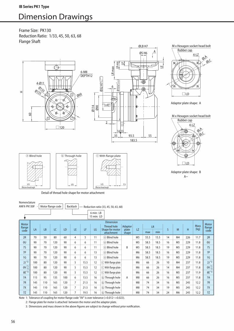
56
Dimension Drawings
Frame Size: PK130Reduction Ratio: 1/33, 45, 50, 63, 68Flange Shaft
M x Hexagon socket head boltRubber cap
4-LZ
4-LZ
M x Hexagon socket head boltRubber cap
ØLA
ØLC
ØLA
ØLC
183.593.5 55
A
2
35
Ø32
H7Ø
90
6
Ø11
4 1×45°
LD
LD
120
Ø60
Ø135Ø155
6-M8DEPTH12
4-Ø11
60
1314
H
LR m
ax
ØLB H7
ØS H6
LR m
in LF
LE
Ø115
h7( 0 -0
.035 )( 0+0
.025
)Adaptor plate shape: A
Adaptor plate shape: BA~
Motorflangecode
DimensionMass[kg]
MotorflangecodeLA LB LC LD LE LF LG
Thread hole Shape for motor
attachment
Adaptorplate
shapeLZ
LRS M H
max min
2R 70 50 80 60 4 5 11 Blind hole
B
M5 55.5 15.5 14 M4 226 11.7 2R
0U 90 70 120 90 6 6 11 Blind hole M5 58.5 18.5 16 M5 229 11.8 0U
7S 90 70 120 90 6 6 11 Blind hole M5 58.5 18.5 19 M5 229 11.8 7S
7P 90 70 120 90 6 6 13 Blind hole M6 58.5 18.5 16 M5 229 11.8 7P
1G 90 70 120 90 6 6 13 Blind hole M6 58.5 18.5 19 M5 229 11.8 1G
2J 100 80 120 90 5 15.5 12 With flange plate
A
M6 66 26 10 M4 237 11.8 2J
0V *1*2 100 80 120 90 5 15.5 12 With flange plate M6 66 26 14 M4 237 11.8 0V *1
*2
8E 100 80 120 90 5 15.5 12 With flange plate M6 66 26 16 M5 237 11.9 8E
7A 115 95 135 100 6 13.5 16 Through hole M8 66 26 16 M5 237 11.8 7A
7R 145 110 165 120 7 21.5 16 Through hole M8 74 34 16 M5 245 12.2 7R
7X 145 110 165 120 7 21.5 16 Through hole M8 74 34 19 M5 245 12.2 7X
7Z 145 110 165 120 7 19.5 16 Through hole M8 74 34 24 M6 245 12.2 7Z
*2 *2
*2 *2
NomenclatureANFX-PK130F Motor flange code Backlash Reduction ratio (33, 45, 50, 63, 68)
6 min: LB15 min: LD
-
Note 1: Tolerance of coupling for motor flange code "0V" is over tolerance (+0.012~+0.023). 2: Flange plate for motor is attached between the motor and the adaptor plate. 3: Dimensions and mass shown in the above figures are subject to change without prior notification.
Detail of thread hole shape for motor attachment
LGE�ective thread length
Blind hole Through hole With �ange plate
LGE�ective thread length
LGLGE�ective thread length
Blind hole Through hole With �ange plate
LGE�ective thread length
LGLGE�ective thread length
Blind hole Through hole With �ange plate
LGE�ective thread length
LG
IB Series PK1 Type

57
Dimension Drawings
PK1
Type
M x Hexagon socket head boltRubber cap
4-LZ
ØLAØLC
183.593.5 55
A
2
35
Ø32
H7Ø
90
6
Ø11
4 1×45°
LD120
Ø60
Ø135Ø155
6-M8DEPTH12
4-Ø11
60
1314
H
LR m
ax
ØLB H7
ØS H6
LR m
in LF
LE
Ø115
h7( 0 -0
.035
)
( 0+0.0
25)
Adaptor plate shape: AA~
Motorflangecode
DimensionMass[kg]
MotorflangecodeLA LB LC LD LE LF LG
Thread hole Shape for motor
attachment
Adaptorplate
shapeLZ
LRS M H
max min
2L 70 50 80 60 4 5 9 Blind hole
A
M4 55.5 15.5 11 M4 226 11.7 2L
2P 70 50 80 60 4 5 9 Blind hole M4 55.5 15.5 14 M4 226 11.7 2P
2H 70 50 80 60 4 5 11 Blind hole M5 55.5 15.5 9 M4 226 11.7 2H
2R 70 50 80 60 4 5 11 Blind hole M5 55.5 15.5 14 M4 226 11.7 2R
8A 90 70 120 90 6 8 11 Blind hole M5 58.5 18.5 11 M4 229 11.8 8A
8B 90 70 120 90 6 8 11 Blind hole M5 58.5 18.5 14 M4 229 11.8 8B
2T 90 70 120 90 6 8 13 Blind hole M6 58.5 18.5 14 M4 229 11.8 2T
2J 100 80 120 90 5 15.5 12 With flange plate M6 66 26 10 M4 237 11.8 2J
8E 100 80 120 90 5 15.5 12 With flange plate M6 66 26 16 M5 237 12.7 8E
*1 *1
*1 *1
NomenclatureANFX-PK130F Motor flange code Backlash Reduction ratio (99, 122, 135, 243)
6 min: LB15 min: LD
-
Frame Size: PK130Reduction Ratio: 1/99, 122, 135, 243Flange Shaft
Note 1: Flange plate for motor is attached between the motor and the adaptor plate. 2: Dimensions and mass shown in the above figures are subject to change without prior notification
Detail of thread hole shape for motor attachment
LGE�ective thread length
Blind hole Through hole With �ange plate
LGE�ective thread length
LGLGE�ective thread length
Blind hole Through hole With �ange plate
LGE�ective thread length
LG
IB Series PK1 Type

Durability Check of Output Shaft Part
0
500
1000
1500
2000
2500
3000
3500
Equivalent moment load [Nm]
Equi
vale
nt ax
ial lo
ad [N
]
Equivalent moment load [Nm]
Equi
vale
nt ax
ial lo
ad [N
]
Equivalent moment load [Nm]
Equi
vale
nt ax
ial lo
ad [N
]
0
1000
2000
3000
4000
5000
6000
0
1000
2000
3000
4000
5000
6000
7000
8000
9000
10000
0 100 200 300 400 500 600 700
0 10 20 30 40 50 60 70 0 100 200 300150 25050
• Consult us when the radial load is exerted on the location exceeding the range of "L + S."• Consult us when the value exceeds the range of allowable load. Units may sometimes be used without problem for some cases, depending on the direction of axial load and the leverage point of the load.
P110 Allowable Load Diagram for Moment and Axial Load
P130 Allowable Load Diagram for Moment and Axial Load
P120 Allowable Load Diagram for Moment and Axial Load
Table 6 DimensionsTable 5 Allowable Moment for P1 Type
LB S L Z
P110 52.76 2 28 19.62
P120 82.56
42.38
64.53 2 42 25.97
P130 109.02 86.26 82 63.24
Nm
P110 7.13
P120 30.6
P130 63.2
103
Frmax · ( Lc + Lr) + Famax · LaMmax = ... (1)
FrmaxN
[kgf]
FamaxN
[kgf]
Lr, Lc, La mm
4
70
300
620
kgfm LC
Make sure that: Mmax ≤ Mc
Refer to Fig. 6.
Maximum radial load during the operation pattern
Maximum axial load during the operation pattern
Load application location
Allowable moment McFrame size
Frame size
Dimension [mm]
R A
R B
Z (L - Z)
(Lr + LC - LB)
LB
L S
Lr LC
Output shaft
*Fr1, Fr2, ······
*Fa1, Fa2, ······
Output flange
Bearing A Bearing B
(S+LC)
P1 Type of IB Series uses angular bearing to allow high maximum load moment.
Make sure that your load moment do not exceed the allowable value through the following calculation.
1. Check Maximum Load MomentTable 4 Symbol in Formula (1)
*: *Refer to Fig. 6. Fig. 6 shows the load of each period in the specific operation pattern.
Fig. 5 External Load Effect diagram
58
IB Series PK1 Type

PK1
Type
Durability Check of Output Shaft Part
t1 t2
Fa1
Fa2
t3
Fa3
Fr1
Fr2
Fr3
n1
n2
n3
t4
+
+
+
Time
Time
Time
Out
put s
peed
Axia
l loa
dRa
dial
load
Table 7 Axial Load Direction and Dynamic Equivalent Load Formula
Fig. 6 Example of Load Fluctuation
Check lifetime by converting to equivalent load when radial or axial load varies.
( ) ( ) ( )3
2211
33
222
3
111
nn
nnn
tntntn
FrtnFrtnFrtnFre
+++·
++=
···
······ (2)
( ) ( ) ( )3
2211
33
222
3
111
nn
nnn
tntntn
FatnFatnFatnFae
+++
++=
···
······ (3)
n
nn
ttt
tntntnNeo
···
···
++
+++=
21
2211 ··· (4)
FaeY
F BaA +=
22aAAA
< =
22 22 Y
RFae
Y
R AB ≥+
BB RP =
AA RP =
22 22 Y
RFae
Y
R AB <+
FaeY
RF A
aB =22
aBBB Y FX RP +=
< =
AA RP =
FaeY
R
Y
R AB +22 22
≤
FaeY
RF A
aB +=22
aBBB Y FX RP +=
=
< =
FaeY
RF B
aA =22
aAAA Y FX RP +=
< =Fae
Y
R
Y
R AB +>22 22
BB RP
·
· ·
· ·
·
·
· ··
·
··
··
··
· ··
R P X R Y F+= · ·
· ·
· ·
· ·
Equivalent radial load: Fre
Equivalent axial load: Fae
Equivalent autput speed: Neo
Axial Load Direction Load Condition Axial Load Dynamic Equivalent Load
-
-
-
-
(Applied to motor side)
(Applied to output side)
Note: When PA RA, use PA RA.
Note: When PB RB, use PB RB.
Note: When PB RA, use PB RA.
Note: When PA RA, use PA RA.
Bearing Category
Bearing A
Bearing B
Bearing A
Bearing B
Bearing A
Bearing B
Bearing A
Bearing B
2. Check Equivalent Load Bearing Lifetime
59
IB Series PK1 Type

36
1060
10=
PFsCf
C
Ne oL h ··· (5)
P N (kgf)
BA RR , N (kgf) -
X
Y
2Y >
-
BA FaFa , N (kgf) -
Dynamic rated load C X Y
Frame size
N (kgf) eRF AaA ≥/
eRF BaB ≥/
eRF AaA >/
eRF BaB >/
eRF AaA ≥/
eRF BaB ≥/
eRF AaA >/
eRF BaB >/
e
P110 3050
P120 8950
P130 13600
1 0 1.14
hL 10
Fs
1.0
1.0 -1.2
1.4 -1.6
Cf
1.00
1.25
1.50
Neo r/min
P N (kgf)
C N (kgf)
Cf -
Fs -
0.35 0.57
· · ·
Load Factor
(310)
(910)
(1390)
Lifetime
Refer to Table 7 in page 81.
Refer to Table 8 below.
Axial load factor Y2 = 0.57 when Fa* / R* e
Dynamic equivalent load(Either the larger one of dynamic equivalent load PA or PB, each influencing bearing A and B)
Support reaction applied to each bearing A and B calculated from equivalent external load Fre and Fae
Radial load factor
Axial load factor
Axial load exerted on each of bearing A and B
Refer to Table 8.
Refer to Table 7.
Refer to Table 5.
Refer to Table 4.
Refer to formula (4).Equivalent output speed
Dynamic equivalent load
Dynamic rated load
Connected load
Shock factor
Coupling Method
Chain
Gears
V-Belt
Degree of shock
Practically no shock
Light shock
Severe shock
Durability Check of Output Shaft Part
Table 8 Main Bearing Specification
Table 9 Symbols in Table 7 & 8
Table 10 Coupling Factor Cf Table 11 Shock Factor Fs
Table 12 Symbols in Formula (5)
60
IB Series PK1 Type

PK1
Type
Formula for Calculation of Moment of Inertia and GD2
d
• Formula to Calculate Moment of Inertia and GD2
d2 d1
b
c
a
b
c
a
b
cy
a
d
d
d
y
d
R
d
d
p[kg/m3]
Location of rotation Shape
Cylinder
Cylinder
Cylinder
Cylinder
· π · d2 · L · p
Center of axle L
L
L
L
L
L
Center of axle
Center of axle
1–4
Cylinderhollow
Rectangularsolid
Rectangularsolid
Rectangularsolid
Cone
Torus
Sphere
MassM [kg]
Moment of InertiaJ [kgm2]
GD2
GD2 [kgf·m2]
p[kg/m3]
p[kg/m3]
p[kg/m3]
p[kg/m3]
p[kg/m3]
p[kg/m3]
p[kg/m3]
p[kg/m3]
p[kg/m3]
p[kg/m3]
· π · d4 · L · p1–32 · π · d4 · L · p
1–8
· π · d2 · L · p1–4
· π · d2 · L · p1–4
· π · d2 · L · p1–4
48y · L + 48y2) · p
· π · d2 · p1–6 · π · d5 · p
1––60
· π2 · R · d2 · p1–2 · (4R2 + ) · p
π2 · R · d2–––––––––
83d2–––
4
· (16L2 + 3d2 + π · d2 · L–––––––
192
12b · y + 12y2) · p
· (4b2 + c2 +a · b · c–––
12
· (b2 + c2) · pa · b · c–––
12
· (4L + 3d2) · pπ · d2 · L–––––––
192
· π · d2 · L · p1––
12 · π · d4 · L ·p1–––
160
· π · (d12 - d2
2) · L · p1–4 · π · (d1
4 - d24) · L · p
1––32 · π · (d1
4 - d24) · L · p
1–8
a · b · c · p
a · b · c · p
a · b · c · p
Dimension: d, L , a, b, c, y, R [m]Density: p[kg/m3]
Edge axle
Eccentricity
Horizontalcenteraxis
Horizontaledgeaxis
HorizontalEccentricity
Center of axle
Center of axle
Center of axle
· (b2 + c2) · pa · b · c–––
3
· (4b2 + c2) · pa · b · c–––
12 · (4b2 + c2) · p
a · b · c–––
3
12b · y + 12y2) · p
· (4b2 + c2 +a · b · c–––
3
· (4L + 3d2) · pπ · d2 · L–––––––
48
· (16L + 3d2) · pπ · d2 · L–––––––
192 · (16L + 3d2) · pπ · d2 · L–––––––
48
48y · L + 48y2) · p
· (16L2 + 3d2 + π · d2 · L–––––––
48
· π · d5 · p1––
15
· π · d4 · L ·p1––
40
· (4R2 + ) · pπ2 · R · d2––––––––
23d2–––
4
61
IB Series PK1 Type
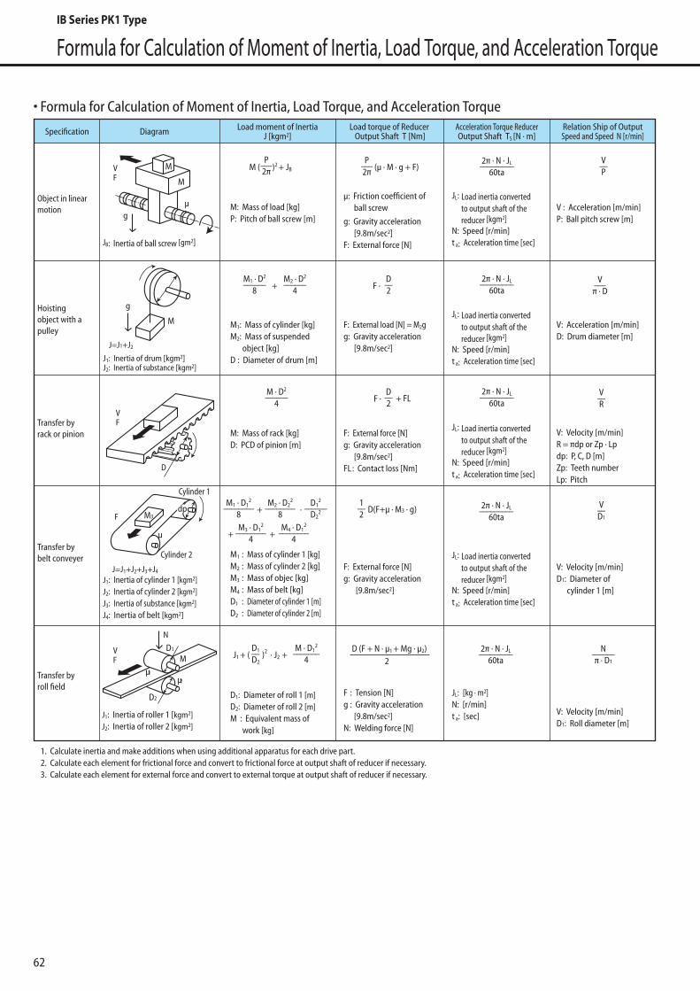
Formula for Calculation of Moment of Inertia, Load Torque, and Acceleration Torque
• Formula for Calculation of Moment of Inertia, Load Torque, and Acceleration Torque
M: Mass of load [kg]P: Pitch of ball screw [m]
M1: Mass of cylinder [kg]M2: Mass of suspended object [kg]D : Diameter of drum [m]
g: Gravity acceleration [9.8m/sec2]F: External force [N]
F: External load [N] = M2gg: Gravity acceleration [9.8m/sec2]
JL: Load inertia converted to output shaft of the reducer [kgm2]N: Speed [r/min]t a: Acceleration time [sec]
JL: Load inertia converted to output shaft of the reducer [kgm2]N: Speed [r/min]t a: Acceleration time [sec]
M: Mass of rack [kg]D: PCD of pinion [m]
F: External force [N]g: Gravity acceleration [9.8m/sec2]FL : Contact loss [Nm]
JL: Load inertia converted to output shaft of the reducer [kgm2]N: Speed [r/min]t a: Acceleration time [sec]
F: External force [N]g: Gravity acceleration [9.8m/sec2]
JL: Load inertia converted to output shaft of the reducer [kgm2]N: Speed [r/min]t a: Acceleration time [sec]
F : Tension [N]g : Gravity acceleration [9.8m/sec2]N: Welding force [N]
JL: [kg · m2]N: [r/min]t a: [sec]
JB: Inertia of ball screw [gm2]
J1: Inertia of drum [kgm2]J2: Inertia of substance [kgm2]
J=J1+J2
J1: Inertia of cylinder 1 [kgm2]J2: Inertia of cylinder 2 [kgm2]J3: Inertia of substance [kgm2]J4: Inertia of belt [kgm2]
M1 : Mass of cylinder 1 [kg]M2 : Mass of cylinder 2 [kg]M3 : Mass of objec [kg]M4 : Mass of belt [kg]D1 : Diameter of cylinder 1 [m]D2 : Diameter of cylinder 2 [m]
D1: Diameter of roll 1 [m]D2: Diameter of roll 2 [m]M : Equivalent mass of work [kg]
J1: Inertia of roller 1 [kgm2]J2: Inertia of roller 2 [kgm2]
J=J1+J2+J3+J4
Object in linear motion
Specification Diagram Load moment of InertiaJ [kgm2]
Load torque of Reducer Output Shaft T [Nm]
Acceleration Torque ReducerOutput Shaft TS [N · m]
Relation Ship of OutputSpeed and Speed N [r/min]
Hoisting object with a pulley
Transfer by rack or pinion
Transfer by belt conveyer
Transfer by roll field
P–––2πM ( )2 + JB
M1 · D2
––––––8
M2 · D2
––––––4+
D––2F ·
P–––2π
V: Acceleration [m/min]D: Drum diameter [m]
V–––π · D
M · D2
––––––4
D––2F ·
V: Velocity [m/min]R = πdp or Zp · Lpdp: P, C, D [m]Zp: Teeth number Lp: Pitch
V––R
V: Velocity [m/min]D1: Diameter of cylinder 1 [m]
V––D1
V: Velocity [m/min]D1: Roll diameter [m]
M1 · D12
––––––––8
M2 · D22
––––––––8
D12
––––––D2
2
(µ · M · g + F)
+
M · D12
–––––––4
D1––D2
2π · N · JL–––––––––60ta
J1 + ( )2 · J2 +
M3 · D12
––––––––4+
M4 · D12
––––––––4+
·
1. Calculate inertia and make additions when using additional apparatus for each drive part.2. Calculate each element for frictional force and convert to frictional force at output shaft of reducer if necessary. 3. Calculate each element for external force and convert to external torque at output shaft of reducer if necessary.
gµ
M
M
g
M
VF
µ
M3Fdp
Cylinder 1
Cylinder 2
VF
µ1
M
µ2
N
VF
+ FL
1––2 D(F+µ · M3 · g)
D (F + N · µ1 + Mg · µ2)2
V––P
V : Acceleration [m/min]P: Ball pitch screw [m]
N––––––π · D1
D
D2
D1
µ: Friction coefficient of ball screw
2π · N · JL–––––––––60ta
2π · N · JL–––––––––60ta
2π · N · JL–––––––––60ta
2π · N · JL–––––––––60ta
62
IB Series PK1 Type
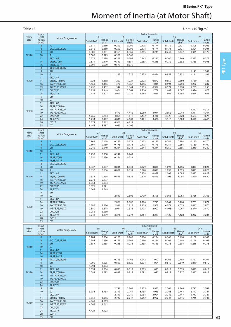
PK1
Type
Moment of Inertia (at Motor Shaft)
Table 13 Unit: x10-4kg•m2
Framesize
Inputshaft
hollow[mm]
Motor flange code
Reduction ratio6 8 11 15 23
Solid shaft Flange shaft Solid shaft Flange
shaft Solid shaft Flange shaft Solid shaft Flange
shaft Solid shaft Flange shaft
PK110
6 7J 0.311 0.310 0.299 0.299 0.175 0.174 0.172 0.171 0.305 0.3058 2C,2D,2E,2F,2G 0.310 0.310 0.299 0.298 0.174 0.174 0.171 0.171 0.304 0.3049 2H 0.381 0.381 0.369 0.369 0.245 0.245 0.242 0.242 0.375 0.375
10 2J 0.380 0.379 0.368 0.36811 2K,2L,8A 0.379 0.378 0.367 0.367 0.243 0.243 0.240 0.240 0.373 0.37314 2P,2R,2T,8B 0.371 0.370 0.359 0.359 0.235 0.235 0.232 0.232 0.365 0.36516 7P,8E,7A,7R 0.591 0.590 0.579 0.579
PK120
8 2C,2D,2E,2F,2G9 2H 1.141 1.141
10 2J 1.229 1.226 0.875 0.874 0.853 0.852 1.141 1.14111 2K,2L,8A14 2P,2R,2T,8B,0V 1.323 1.318 1.227 1.224 0.873 0.872 0.850 0.850 1.139 1.13816 7A,7P,7R,8E,0U 1.460 1.455 1.370 1.367 1.016 1.015 0.994 0.993 1.282 1.28219 1G,7B,7S,7V,7X 1.437 1.432 1.347 1.344 0.993 0.992 0.971 0.970 1.259 1.25822 0W,0Y,1S 2.154 2.149 2.064 2.061 1.710 1.709 1.688 1.687 1.976 1.97524 1L,7Z,7Y 2.132 2.127 2.041 2.039 1.688 1.686 1.665 1.665 1.954 1.953
PK130
9 2H10 2J11 2K,2L,8A14 2P,2R,2T,8B,0V16 7A,7P,7R,8E,0U 4.317 4.31119 1G,7B,7S,7V,7X 4.479 4.446 3.060 3.044 2.956 2.948 4.311 4.30422 0W,0Y,1S 5.265 5.203 4.851 4.818 3.432 3.416 3.328 3.320 4.683 4.67624 1L,7Z,7Y 5.254 5.192 4.841 4.807 3.421 3.406 3.318 3.309 4.672 4.66628 0Z,1T 5.374 5.312 4.960 4.92735 0X 8.448 8.387 8.035 8.002
Framesize
Inputshaft
hollow[mm]
Motor flange code
Reduction ratio27 33 45 50 63
Solid shaft Flange shaft Solid shaft Flange
shaft Solid shaft Flange shaft Solid shaft Flange
shaft Solid shaft Flange shaft
PK110
6 7J 0.169 0.169 0.173 0.173 0.173 0.173 0.284 0.284 0.170 0.1708 2C,2D,2E,2F,2G 0.169 0.169 0.173 0.173 0.173 0.173 0.284 0.284 0.169 0.1699 2H 0.240 0.240 0.244 0.244 0.244 0.244 0.355 0.355 0.240 0.240
10 2J11 2K,2L,8A 0.238 0.238 0.242 0.24214 2P,2R,2T,8B 0.230 0.230 0.234 0.23416 7P,8E,7A,7R
PK120
8 2C,2D,2E,2F,2G9 2H 0.837 0.837 0.831 0.831 0.829 0.828 1.096 1.096 0.823 0.823
10 2J 0.837 0.836 0.831 0.831 0.828 0.828 1.095 1.095 0.823 0.82311 2K,2L,8A 0.828 0.828 1.095 1.095 0.822 0.82214 2P,2R,2T,8B,0V 0.834 0.834 0.828 0.828 0.826 0.826 1.093 1.093 0.820 0.82016 7A,7P,7R,8E,0U 0.978 0.97719 1G,7B,7S,7V,7X 0.954 0.95422 0W,0Y,1S 1.671 1.67124 1L,7Z,7Y 1.649 1.649
PK130
9 2H10 2J 2.810 2.808 2.799 2.798 3.963 3.963 2.766 2.76611 2K,2L,8A14 2P,2R,2T,8B,0V 2.808 2.806 2.796 2.795 3.961 3.960 2.763 2.87716 7A,7P,7R,8E,0U 2.887 2.884 2.921 2.919 2.909 2.908 4.074 4.073 2.877 2.87619 1G,7B,7S,7V,7X 2.880 2.878 2.914 2.913 2.903 2.902 4.068 4.067 2.870 2.87022 0W,0Y,1S 3.252 3.25024 1L,7Z,7Y 3.241 3.239 3.276 3.274 3.264 3.263 4.429 4.428 3.232 3.23128 0Z,1T35 0X
Framesize
Inputshaft
hollow[mm]
Motor flange code
Reduction ratio68 99 122 135 243
Solid shaft Flange shaft Solid shaft Flange
shaft Solid shaft Flange shaft Solid shaft Flange
shaft Solid shaft Flange shaft
PK110
6 7J 0.284 0.284 0.168 0.168 0.284 0.284 0.168 0.168 0.168 0.1688 2C,2D,2E,2F,2G 0.284 0.284 0.168 0.168 0.284 0.284 0.168 0.168 0.168 0.1689 2H 0.355 0.355 0.238 0.238 0.355 0.355 0.238 0.238 0.238 0.238
10 2J11 2K,2L,8A14 2P,2R,2T,8B16 7P,8E,7A,7R
PK120
8 2C,2D,2E,2F,2G 0.768 0.768 1.042 1.042 0.768 0.768 0.767 0.7679 2H 1.095 1.095 0.820 0.820 1.094 1.094 0.819 0.819 0.819 0.819
10 2J 1.094 1.09411 2K,2L,8A 1.094 1.094 0.819 0.819 1.093 1.093 0.819 0.819 0.819 0.81914 2P,2R,2T,8B,0V 1.092 1.092 0.817 0.817 1.091 1.091 0.817 0.817 0.817 0.81716 7A,7P,7R,8E,0U19 1G,7B,7S,7V,7X22 0W,0Y,1S24 1L,7Z,7Y
PK130
9 2H 2.749 2.749 3.955 3.955 2.748 2.748 2.747 2.74710 2J 3.958 3.958 2.749 2.749 3.955 3.955 2.748 2.748 2.747 2.74711 2K,2L,8A 2.749 2.749 3.954 3.954 2.748 2.747 2.747 2.74714 2P,2R,2T,8B,0V 3.956 3.956 2.747 2.747 3.952 3.952 2.746 2.745 2.745 2.74516 7A,7P,7R,8E,0U 4.069 4.06919 1G,7B,7S,7V,7X 4.063 4.06222 0W,0Y,1S24 1L,7Z,7Y 4.424 4.42328 0Z,1T35 0X 63
IB Series PK1 Type

GD2 (at Motor Shaft)
Unit: x10-4kg•m2Table 14
Framesize
Inputshaft
hollow[mm]
Motor flange code
Reduction ratio6 8 11 15 23
Solid shaft Flange shaft Solid shaft Flange
shaft Solid shaft Flange shaft Solid shaft Flange
shaft Solid shaft Flange shaft
PK110
6 7J 1.243 1.240 1.196 1.194 0.698 0.697 0.686 0.686 1.218 1.2188 2C,2D,2E,2F,2G 1.242 1.240 1.195 1.194 0.697 0.697 0.686 0.685 1.217 1.2179 2H 1.525 1.522 1.478 1.477 0.980 0.980 0.968 0.968 1.500 1.500
10 2J 1.520 1.518 1.473 1.47211 2K,2L,8A 1.516 1.513 1.469 1.468 0.971 0.971 0.959 0.959 1.491 1.49114 2P,2R,2T,8B 1.484 1.482 1.437 1.436 0.939 0.939 0.928 0.927 1.459 1.45916 7P,8E,7A,7R 2.364 2.362 2.317 2.316
PK120
8 2C,2D,2E,2F,2G9 2H 4.566 4.563
10 2J 4.916 4.905 3.501 3.496 3.411 3.408 4.564 4.56211 2K,2L,8A14 2P,2R,2T,8B,0V 5.293 5.273 4.907 4.896 3.492 3.487 3.402 3.399 4.555 4.55316 7A,7P,7R,8E,0U 5.841 5.821 5.481 5.470 4.066 4.061 3.976 3.973 5.129 5.12719 1G,7B,7S,7V,7X 5.748 5.728 5.387 5.376 3.972 3.967 3.882 3.879 5.035 5.03322 0W,0Y,1S 8.617 8.596 8.256 8.245 6.841 6.836 6.751 6.748 7.904 7.90224 1L,7Z,7Y 8.527 8.506 8.166 8.155 6.751 6.746 6.661 6.658 7.814 7.812
PK130
9 2H10 2J11 2K,2L,8A14 2P,2R,2T,8B,0V16 7A,7P,7R,8E,0U 17.270 17.24219 1G,7B,7S,7V,7X 17.918 17.785 12.239 12.177 11.826 11.792 17.245 17.21722 0W,0Y,1S 21.060 20.813 19.406 19.273 13.727 13.666 13.314 13.281 18.733 18.70624 1L,7Z,7Y 21.016 20.770 19.362 19.230 13.684 13.622 13.270 13.237 18.689 18.66228 0Z,1T 21.495 21.249 19.841 19.70935 0X 33.794 33.547 32.140 32.008
Framesize
Inputshaft
hollow[mm]
Motor flange code
Reduction ratio27 33 45 50 63
Solid shaft Flange shaft Solid shaft Flange
shaft Solid shaft Flange shaft Solid shaft Flange
shaft Solid shaft Flange shaft
PK110
6 7J 0.678 0.678 0.693 0.693 0.692 0.692 1.137 1.137 0.679 0.6798 2C,2D,2E,2F,2G 0.677 0.677 0.693 0.692 0.691 0.691 1.137 1.137 0.678 0.6789 2H 0.960 0.960 0.975 0.975 0.974 0.974 1.420 1.420 0.961 0.961
10 2J11 2K,2L,8A 0.951 0.951 0.966 0.96614 2P,2R,2T,8B 0.919 0.919 0.935 0.93416 7P,8E,7A,7R
PK120
8 2C,2D,2E,2F,2G9 2H 3.347 3.346 3.324 3.324 3.314 3.314 4.383 4.383 3.292 3.292
10 2J 3.346 3.345 3.323 3.323 3.313 3.313 4.382 4.382 3.291 3.29011 2K,2L,8A 3.312 3.311 4.380 4.380 3.289 3.28914 2P,2R,2T,8B,0V 3.337 3.336 3.314 3.313 3.304 3.304 4.373 4.372 3.281 3.28116 7A,7P,7R,8E,0U 3.911 3.91019 1G,7B,7S,7V,7X 3.817 3.81622 0W,0Y,1S 6.686 6.68524 1L,7Z,7Y 6.596 6.595
PK130
9 2H10 2J 11.240 11.233 11.194 11.190 15.854 15.851 11.065 11.06311 2K,2L,8A14 2P,2R,2T,8B,0V 11.231 11.224 11.185 11.181 15.845 15.842 11.055 11.05316 7A,7P,7R,8E,0U 11.546 11.536 11.682 11.675 11.636 11.633 16.296 16.293 11.507 11.50519 1G,7B,7S,7V,7X 11.521 11.511 11.657 11.651 11.611 11.608 16.271 16.268 11.482 11.48022 0W,0Y,1S 13.009 12.99924 1L,7Z,7Y 12.966 12.956 13.102 13.095 13.056 13.052 17.716 17.713 12.927 12.92528 0Z,1T35 0X
Framesize
Inputshaft
hollow[mm]
Motor flange code
Reduction ratio68 99 122 135 243
Solid shaft Flange shaft Solid shaft Flange
shaft Solid shaft Flange shaft Solid shaft Flange
shaft Solid shaft Flange shaft
PK110
6 7J 1.137 1.137 0.672 0.672 1.136 1.136 0.672 0.672 0.671 0.6718 2C,2D,2E,2F,2G 1.136 1.136 0.671 0.671 1.136 1.136 0.671 0.671 0.671 0.6719 2H 1.419 1.419 0.954 0.954 1.419 1.419 0.954 0.954 0.954 0.954
10 2J11 2K,2L,8A14 2P,2R,2T,8B16 7P,8E,7A,7R
PK120
8 2C,2D,2E,2F,2G 3.071 3.071 4.168 4.168 3.070 3.070 3.070 3.0709 2H 4.379 4.378 3.279 3.279 4.375 4.375 3.277 3.277 3.277 3.277
10 2J 4.377 4.37711 2K,2L,8A 4.376 4.376 3.276 3.276 4.373 4.373 3.275 3.275 3.274 3.27414 2P,2R,2T,8B,0V 4.368 4.368 3.268 3.268 4.365 4.365 3.267 3.267 3.266 3.26616 7A,7P,7R,8E,0U19 1G,7B,7S,7V,7X22 0W,0Y,1S24 1L,7Z,7Y
PK130
9 2H 10.998 10.997 15.820 15.819 10.993 10.992 10.989 10.98910 2J 15.834 15.832 10.997 10.996 15.819 15.818 10.992 10.991 10.988 10.98811 2K,2L,8A 10.995 10.994 15.817 15.817 10.990 10.990 10.986 10.98614 2P,2R,2T,8B,0V 15.824 15.823 10.987 10.987 15.809 15.809 10.982 10.982 10.979 10.97816 7A,7P,7R,8E,0U 16.276 16.27419 1G,7B,7S,7V,7X 16.251 16.24922 0W,0Y,1S24 1L,7Z,7Y 17.696 17.69428 0Z,1T35 0X64
IB Series PK1 Type

PK1
Type
Mechanical Precision of Output Part of the Reducer
Mechanical precision of solid shaft (with and without key) and flange shaft is indicated below.
Output Shaft: Solid Shaft (with and without key)
Output Shaft: Flange Shaft
Ø 0.05 A
0.05 B
Ø 0.05 A
0.060 A
0.05
0.05 A
A
B
A
0.04
Fig. 7
Fig. 8
65
IB Series PK1 Type
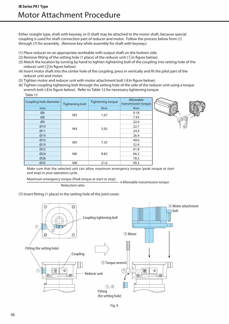
Reducer unit
Fitting (for setting hole)
Coupling
Motor attachment bolt
Fitting (for setting hole)
Motor
Torque wrench
Coupling tightening bolt
Motor Attachment Procedure
Fig. 9
Table 15
Coupling hole diameterTightening bolt
Tightening torque Allowable transmission torque
mm N·m N·mØ6
M3 1.679.18
Ø8 7.93Ø9
M4 3.92
22.0Ø10 22.7Ø11 24.9Ø14 26.4Ø16
M5 7.3549.6
Ø19 52.9Ø22
M6 8.8361.8
Ø24 66.2Ø28 78.3Ø35 M8 21.6 99.2
Either straight type, shaft with keyway, or D shaft may be attached to the motor shaft, because special coupling is used for shaft connection part of reducer and motor. Follow the process below from (1) through (7) for assembly. (Remove key while assembly for shaft with keyway.)
(1) Place reducer on an appropriate worktable with output shaft on the bottom side.(2) Remove fitting of the setting hole (1 place) of the reducer unit ( 1 in figure below).(3) Match the location by turning by hand to tighten tightening bolt of the coupling into setting hole of the reducer unit ( 2 in figure below).(4) Insert motor shaft into the center hole of the coupling, press in vertically and fit the pilot part of the reducer unit and motor. (5) Tighten motor and reducer unit with motor attachment bolt ( 4 in figure below).(6) Tighten coupling tightening bolt through the setting hole of the side of the reducer unit using a torque wrench bolt ( 4 in figure below). Refer to Table 12 for necessary tightening torque.
(7) Insert fitting (1 place) in the setting hole of the joint cover.
Make sure that the selected unit can allow maximum emergency torque (peak torque at start and stop) in your operation cycle.
Maximum emergency torque (Peak torque at start or stop) Allowable transmission torque
Reduction ratio
66
IB Series PK1 Type
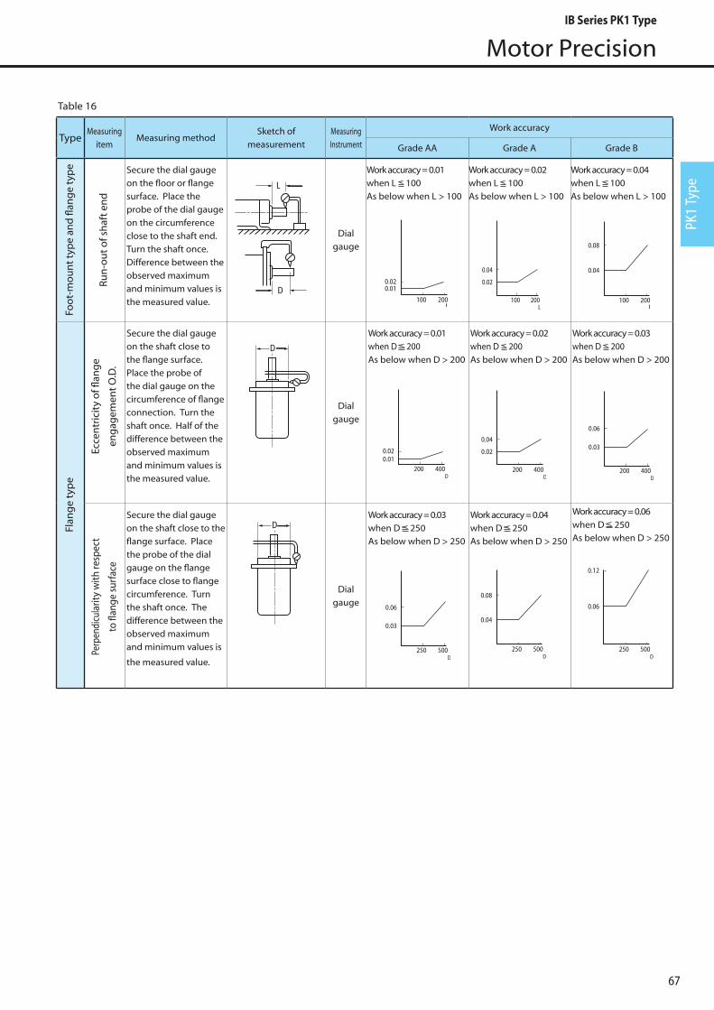
PK1
Type
Motor Precision
TypeMeasuring
itemMeasuring method
Sketch of measurement
Measuring Instrument
Work accuracy
Grade AA Grade A Grade B
Secure the dial gauge on the floor or flange surface. Place the probe of the dial gauge on the circumference close to the shaft end. Turn the shaft once. Difference between the observed maximum and minimum values is the measured value.
Dial gauge
Work accuracy = 0.01 when L 100As below when L > 100
Work accuracy = 0.02 when L 100As below when L > 100
Work accuracy = 0.04 when L 100As below when L > 100
Secure the dial gauge on the shaft close to the flange surface. Place the probe of the dial gauge on the circumference of flange connection. Turn the shaft once. Half of the difference between the observed maximum and minimum values is the measured value.
Dial gauge
Work accuracy = 0.01 when D 200As below when D > 200
Work accuracy = 0.02 when D 200As below when D > 200
Work accuracy = 0.03 when D 200As below when D > 200
Secure the dial gauge on the shaft close to the flange surface. Place the probe of the dial gauge on the flange surface close to flange circumference. Turn the shaft once. The difference between the observed maximum and minimum values is
the measured value.
Dial gauge
Work accuracy = 0.03 when D 250As below when D > 250
Work accuracy = 0.04 when D 250As below when D > 250
Work accuracy = 0.06 when D 250As below when D > 250
D
L
D
D
200 4000.010.02
D
100 200
0.04
0.02
L100 200
0.010.02
L
200 400
0.04
0.02
D
250 500
0.06
0.03
D250 500
0.08
0.04
D250 500
0.06
0.12
D
200 400
0.06
0.03
D
100 200
0.04
0.08
L
Table 16
Foot
-mou
nt t
ype
and
flan
ge
typ
eFl
ang
e ty
pe
Run
-out
of s
haf
t en
d
Ecce
ntr
icit
y of
flan
ge
eng
agem
ent O
.D.
Perp
endi
cula
rity
with
resp
ect
to fl
ange
sur
face
67
IB Series PK1 Type
Warranty
Warranty Period
The warranty period for the Products shall be 18 months after the commencement of delivery or 18 months after the shipment of the Products from the seller's works or 12 months from the Products coming into operation, whichever comes first.
WarrantyCondition
In the event that any problem or damage to the Product arises during the "Warranty Period" from defects in the Product whenever the Product is properly installed and combined with the Buyer's equipment or machines, maintained as specified in the maintenance manual, and properly operated under the condi-tions described in the catalog or as otherwise agree upon in writing between the Seller and the Buyer or its customers; the Seller will provide, at its sole discretion, appropriate repair or replacement of the Prod-uct without charge at a designted facility, except as stipulated in the "Warranty Exclusions" as described below.However, if the Product is installed or integrated into the Buyer's equipment or machines, the Seller shall not reimburse the cost of: removal or re-installation of the Product or other incidental costs related there-to, any lost opportunity, any profit loss or other incidental or consequential losses or damages incurred by the Buyer or its customers.
Warranty Exclusions
Notwithstanding the above warranty, the warranty as set forth herein shall not apply to any problem or damage to the Product that is caused by:1. installation, connection, combination or integration of the Product in or to the other equipment or
machine that is rendered by any person or entity other than the Seller;2. insufficient maintenance or improper operation by the Buyer or its customers, such that the Product is
not maintained in accordance with the maintenance manual provided or designated by the Seller;3. improper use or operation of the Product by the Buyer or its customers that is not informed to the
Seller, including, without limitation, the Buyer's or its customers, operation of the Product not in con-formity with the specifications, or use of lubricating oil in the Product that is not recommended by the Seller;
4. any problem or damage on any equipment or machine to which the Product is installed, connected or combined or on any specifications particular to the Buyer or its customers;
5. any changes, modifications, improvements or alterations to the Product or those functions that are rendered on the Product by any person or entity other than the Seller;
6. any parts in the Product that are supplied or designated by the Buyer or its customers;7. earthquake, fire, flood, sea-breeze, gas, thunder, acts of God or any other reasons beyond the control
of the Seller;8. normal wear and tear, or deterioration of the Products, parts, such as bearings, oil-seals;9. any other troubles, problems or damage to the Product that are not attributable to the Seller.
SAFETY PRECAUTIONS
• Observe the safety rules for the installation site and equipment strictly (Industrial safety and health law, technical standard for electric facilities, extension rules, plant explosion guidelines, building standards law, etc).
• Read the maintenance manual carefully before use. Request a copy from the distributor of the Product or our Sales Department if the maintenance manual is not handy. A copy of maintenance manual should always reach the actual user of the Product.
• Select a sufficient product for the usage condition and application. • Install protective equipment on the machine side when the machine is used for applications which may cause loss of
human life or significant loss in facility, such as use for human transportation or elevators.• Install an oil pan or other preventive devices in case of oil leakage due to failure or termination of service life when the
machine is used for food processing equipment, clean room, or other applications that are sensitive to oil.
68
IB Series PK1 Type