worm-bubble flow control - oregon state...
TRANSCRIPT
Worm-Bubble Flow Control
Lizhong Chen and Timothy M. Pinkston Ming Hsieh Department of Electrical Engineering
University of Southern California {lizhongc, tpink}@usc.edu
Abstract Deadlock-free flow control should be designed with minimal cost, particularly for on-chip designs where area and power resources are greatly constrained. While Bubble Flow Control, proposed a decade ago, can avoid deadlock in VCT-switched tori with only one virtual channel (VC), there has been no working solution for wormhole switching that achieves the similar objective. Wormhole switching allows the channel buffer size to be smaller than the packet size, thus is preferred by on-chip networks. However, wormhole packets can span multiple routers, thereby creating addi-tional channel dependences and adding complexities in both deadlock and starvation avoidance. In this paper, we pro-pose Worm-Bubble Flow Control (WBFC), a new flow control scheme that can avoid deadlock in wormhole-switched tori using minimally 1-flit-sized buffers per VC and one VC in total. Moreover, any wormhole-switched topology with embedded rings can use WBFC to avoid deadlock within each ring. Simulation results from synthetic traffic and PARSEC benchmarks show that the proposed approach can achieve significant throughput improvement and also area and energy savings compared to an optimized Dateline routing approach.
1. Introduction Deadlock is a critical issue in interconnection network
designs due to its catastrophic consequences to the network and overall computer system performance. Along with routing, network flow control is a key aspect to guaranteeing deadlock freedom in both off-chip and on-chip networks. However, unlike off-chip environments, on-chip designs are much more constrained by limited available resources (e.g., chip area and power). Hence, flow control mechanisms for networks-on-chip (NoCs) must maximize resource utilization while preventing oversubscription and deadlock in resource usage.
Torus, or k-ary n-cube, topologies are widely used in off-chip [2, 3, 6, 15] and on-chip [14, 28] networks due to low diameter and geometric symmetry. Meanwhile, the wrapa-round links that bring about these advantages also create additional channel dependencies within each dimension. Those dependencies significantly increase the difficulty in designing deadlock-free routing and flow control mecha-nisms which use a minimal number of virtual channels (VCs) and support wormhole switching that is useful to resource-constrained NoCs. A classic approach to this issue is the Dateline technique [13], which works for both virtual cut-through switching (VCT switching) and wormhole switching, but it requires at least two VCs per link to avoid deadlock within any unidirectional ring in a torus. To reduce the VC cost, a simple yet powerful bubble flow control (BFC) technique [29] was proposed that can avoid such deadlock in VCT-switched tori using only one VC.
While the theoretically minimal VC requirement (i.e., one
VC) is achievable in VCT switching with BFC proposed a decade ago, there has been no working solution for worm-hole switching that achieves the similar goal. The advantage of wormhole switching is its allowance of buffer size to be smaller than the packet size (i.e., minimally the size of the packet header), but this introduces additional dependences between upstream and downstream channels. In addition, the local buffer need not have the capacity to accept the entire injecting packet, thus requiring coordination of buffer re-sources on remote nodes in order to guarantee the existence of a bubble in the ring. Moreover, each packet can now occupy several VCs, potentially causing starvation when multiple packets are being injected simultaneously. Due to these added complexities, the extension of BFC to wormhole switching is a very challenging problem.
In this paper, we propose Worm-Bubble Flow Control (WBFC), a new flow control scheme that can avoid deadlock in wormhole-switched tori using minimally 1-flit-sized buffers per VC and one VC in total. The basic idea is to use VC-sized worm-bubbles as the unit of flow control, and appropriately color them as white, gray or black to convey and coordinate global buffer resource information locally, thereby overcoming the dependence and starvation problems caused by small buffer size in wormhole switching. Further-more, WBFC is not limited to unidirectional rings only in torus networks. Any wormhole-switched topology that contains rings can use WBFC to avoid deadlock within the rings. WBFC has both theoretical value and practical appli-cation. The main contributions of this paper are the following: Challenges in achieving deadlock-free flow control for
wormhole-switched tori with minimal VC requirement are identified;
A new scheme and theoretical support for Worm-Bubble Flow Control is proposed, which overcomes all the ma-jor challenges caused by BFC for wormhole switching;
Full system simulations show the correctness and effectiveness of the proposed WBFC, with significant throughput improvement and also area and energy sav-ings compared to an optimized Dateline approach.
The rest of the paper is organized as follows. Section 2 provides more background on the resource cost in NoCs and identifies the difficulties in achieving efficient flow control for wormhole-switched tori. Section 3 explains the details of the theoretical support and implementation approach for WBFC. Section 4 describes our evaluation methodology, and Section 5 presents simulation results. Section 6 discusses the applications and extensions of WBFC to other scenarios. Finally, related work is summarized in Section 7, and Section 8 concludes the paper.
2. Background and Motivation 2.1 Need for Efficient and Low Cost Flow Control
Most flow control mechanisms are based on the use of virtual channels [12] to prevent deadlock and enable adaptiv-
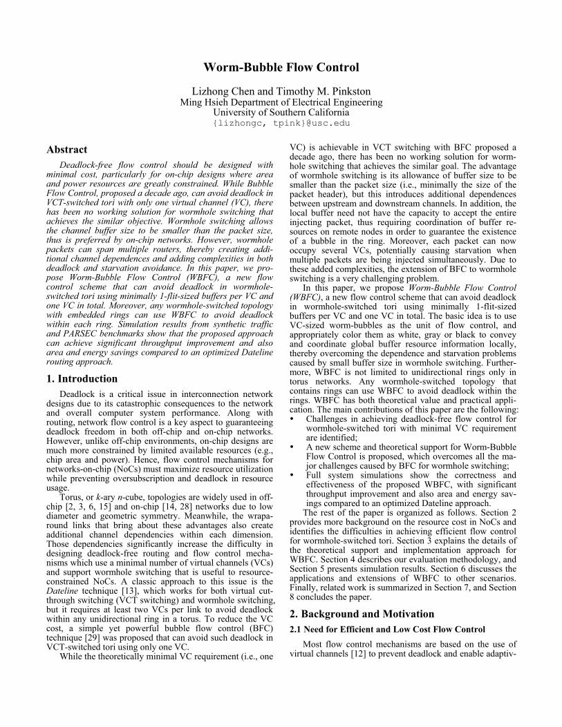
ity in routing algorithms. Taking torus networks as an exam-ple, to prevent any potential deadlock within dimensions caused by torus wraparound links, the Dateline technique can be used in which two virtual channels (high and low) are associated with each physical channel [13]. When packets transported on low channels cross the dateline, they switch to high channels thus breaking cyclic dependency within dimensions. Together with dimension-order routing (DOR) that eliminates cyclic dependencies across different dimen-sions, Dateline can achieve deadlock-free deterministic routing for tori using two VCs. To enable adaptive routing, additional VCs are needed to act as adaptive resources (e.g., applying Duato’s Protocol [16]) whereas the original two VCs serve as escape resources. Therefore, the minimal number of VCs for Dateline to achieve deadlock-free adap-tive routing and deterministic routing are 3 and 2, respectively. To illustrate the area and power cost of imple-menting VCs, Figure 1 plots the breakdown of router area and power for different number of VCs at 45nm with 2GHz frequency and 1.1V operating voltage. Results are obtained from the Orion 2.0 NoC model [22] fed with statistics from full system simulation (more details of the simulation infra-structure are described in Section 4).
As shown in Figure 1(a), even with a relatively small buffer size of 3-flits per VC and wormhole switching, the percentage of buffer area in Dateline with adaptive routing (i.e., the 3VC bar) exceeds 43% of the total router area. This percentage drops to 35% when 2VCs are used in Dateline but with the loss of routing adaptivity. Now, consider a flow control mechanism F that is devised to avoid deadlock in DOR by using only one VC and, thus, can realize adaptive routing for tori with two VCs. Compared to Dateline adap-tive and deterministic, F can reduce the buffer area by 33% and 50%, respectively (which corresponds to a savings of 18% and 22% of total router area, respectively). From the power perspective, as shown in Figure 1(b), similar gaps also exist when different numbers of VCs are used. While dynamic power is largely determined by the workload, static power closely correlates to hardware cost. As can be seen, the buffer is a significant source of static power consumption; however, buffer static power per router can be reduced from 0.087W (21% of total router power) at 3VCs, to 0.058W (16% of total) at 2VCs and 0.029W (11% of total) at 1 VC, indicat-ing that minimizing the number of VCs is important for keeping the buffer cost low.
It is worth noting that the number of VCs does not only affect buffer resources, but also has considerable impact on the cost of router control logic, particularly the VC allocator (VA) and switch allocator (SA). SA is affected as the input-arbitration step in SA is to select one VC from multiple VCs within the same physical channel to participate in the output-
arbitration step in SA. As shown in Figure 1, with a fewer number of VCs per link, the area and power of control logic also decrease substantially (more than halved from 3VCs to 1VC). Moreover, as pointed out in [8], fewer VCs also simplifies VA and SA implementation, thus potentially reducing the delay on the critical path of the router pipeline.
Another major factor that influences the cost of flow con-trol is whether VCT switching or wormhole switching is used. To facilitate the discussion throughout the paper, we first introduce some basic definitions derived from [11, 18]. Definition 1. Let Q be the set of input queues associated with router nodes. Each queue qi ∈ Q has capacity of cap(qi) measured in the number of flits, and the current number of flits occupying the queue is denoted as size(qi). For any packet p, L(p) is the length of p measured in number of flits.
With this definition, the head flit of a packet p is allowed to enter the downstream receiving queue q for VCT switch-ing if
cap(q) – size(q) ≥ L(p), (1) whereas for wormhole switching the condition is
cap(q) – size(q) ≥ 1. (2) Note that for VCT switching, in order to allow any packet
to access a specific queue q, (1) should hold for all packets, thereby requiring the capacity of q to be at least the length of the longest packet. Meanwhile, as all flits belonging to the same packet are guaranteed to be received at q once the head flit gains access, a variety of deadlock issues caused by indirect dependence can be simplified [16]. Therefore, VCT switching is preferred in off-chip interconnects where buffer resources are abundant [2, 3]. In contrast, wormhole switch-ing adds complexities to deadlock avoidance, but it requires minimally only one flit-sized buffer per VC according to Equation (2) above. Hence, due to the low buffer require-ment, wormhole switching is much preferred in resource-constrained on-chip environments [20, 21].
In sum, considering the impact of reducing the number of VCs on router area/power and the need for supporting wormhole switching in NoCs, it is imperative to devise an efficient flow control mechanism that can avoid deadlock under wormhole switching using a minimal number of VCs. 2.2 Bubble Flow Control for VCT Switching
Ideally, flow control should prevent deadlock in tori us-ing only one VC. For VCT switching, this goal is achievable with bubble flow control (BFC) [29].
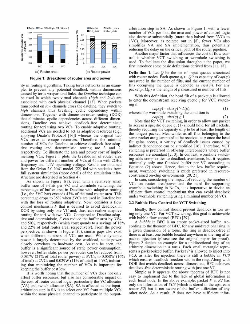
A bubble in BFC is an empty packet-sized buffer. Ac-cording to the theorem of BFC, for any unidirectional ring in a given dimension of a torus, the ring is deadlock-free if there is at least one bubble located anywhere in the ring after packet injection (please see the original paper for proof). Figure 2 depicts an example for a unidirectional ring of an arbitrary dimension in a torus. Each small rectangle repre-sents a packet-sized buffer. Packet P is allowed to inject into VC3, as after the injection there is still a bubble in VC0 which ensures deadlock freedom within the ring. Along with DOR that avoids deadlock across dimensions, BFC achieves deadlock-free deterministic routing with just one VC.
Simple as it appears, the above theorem of BFC is not easy to implement due to the lack of global information at each local node. In the above example, packet P at R2 has only the information of VC3 (which is stored in the upstream router R2) but is not aware of the buffer utilization of any other node. As a result, P does not have sufficient infor-
0.0
1.0
2.0
3.0
4.0
5.0
3VC 2VC 1VC
Brea
kdow
n of
rou
ter a
rea
( ×10
5µm
2)Buffer Xbar Ctrl logic (VA, SA, etc.)
0
0.05
0.1
0.15
0.2
0.25
0.3
3VC 2VC 1VC
Brea
kdow
n of
rou
ter p
ower
(W)
Dynamic Buffer_staticCtrl_static Xbar_static
(a) Router area (b) Router power
Figure 1: Breakdown of router area and power.
mation to make an optimal decision. To circumvent the difficulty of acquiring global information, early implementa-tions of BFC adopted a localized version, in which each injecting packet simply checks whether there are two bubbles in the local receiving buffer. This localized BFC scheme essentially requires each buffer to be large enough to hold at least two packets, causing low buffer utilization in many cases.
A more efficient implementation of BFC is the Critical Bubble Scheme (CBS) [11], which cleverly conveys the global information locally by using the notion of a critical bubble. However, CBS is applicable only to VCT switching. As exemplified in Figure 3, an empty packet-sized buffer in any router along a ring is marked as the critical bubble for the entire ring (e.g., the black rectangle in VC4). This critical bubble can only be used by packets that are already in the ring, but cannot be used by injecting packets. For instance, P1 is allowed to inject as there is at least one non-critical bubble in VC2, whereas P2 is not allowed to inject as the only bubble in VC4 is the critical bubble. Essentially, the absence of the critical bubble at VC2 indicates the existence of a bubble (i.e., the critical bubble) elsewhere in the ring, thus providing implicit global information. CBS only needs each buffer to be at least one packet-size, and if more than one packet is injecting simultaneously (e.g., P1 and P2 are injecting in the same cycle), it is clear which one should be injected and which one should not, based only on local information. In addition, the critical bubble can be displaced backward in the ring either proactively (e.g., if VC3 is empty and P2 is waiting for injection), or by the incoming packet (e.g., P3 occupying the critical bubble will mark the newly freed buffer in VC3 as the critical bubble, so logically the critical bubble is simply transferred backwards rather than consumed). In both cases, the existence of the critical bubble in the ring is always maintained, ensuring that not all buffers are fully occupied. 2.3 Challenges in Extending BFC for Wormhole
As stated, BFC with its efficient implementation of CBS achieves deadlock-free deterministic routing for VCT-switched tori using only one VC. Considering the potential resource savings of reducing the number of VCs and the importance of supporting wormhole switching in NoCs, significant gains can be obtained if BFC could be extended to wormhole-switched tori as well. However, the added channel dependence introduced by wormhole switching and the allowance of buffer size being smaller than the packet
size cause several major difficulties in extending both the BFC theorem and its implementation to wormhole. 2.3.1 Atomic Buffer Allocation in Wormhole Switching
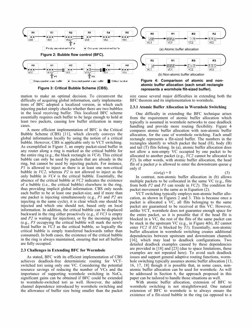
One difficulty in extending the BFC technique arises from the requirement of atomic buffer allocation which typically is assumed in wormhole networks to ease deadlock handling and provide more routing flexibility. Figure 4 compares atomic buffer allocation with non-atomic buffer allocation, for the case of wormhole switching. Each small rectangle represents a flit-sized buffer. The numbers in the rectangles identify to which packet the head (H), body (B) and tail (T) flits belong. In (a), atomic buffer allocation does not allow a non-empty VC occupied by one packet to be allocated to another packet (e.g., VC2 cannot be allocated to P2). In other words, with atomic buffer allocation, the head flit of a packet p is allowed to enter the downstream queue q only if
size(q) = 0 (3) In contrast, non-atomic buffer allocation in (b) allows
multiple packets to be collocated in the same VC (e.g., flits from both P2 and P1 can reside in VC2). The condition for packet movement is the same as in Equation (2).
VCT switching typically employs non-atomic buffer allo-cation, as shown in Figures 2 and 3. This is because once a packet is allocated a VC, all flits belonging to the same packet are guaranteed to be received at this VC. However, unlike VCT, wormhole does not guarantee enough space for the entire packet, so it is possible that if the head flit is blocked in a VC, the rest of the flits of the same packet can be stuck in the upstream VC (e.g., in Figure 4(b), B2 cannot enter VC2 if H2 is blocked by T1). Essentially, non-atomic buffer allocation in wormhole switching creates additional dependencies between upstream and downstream channels [16], which may lead to deadlock configurations. Two detailed deadlock examples caused by these dependencies are provided in [18] and [23] (due to space limitations, these examples are not repeated here). To avoid such deadlock issues and support general adaptive routing functions, worm-hole switching typically assumes atomic buffer allocation [13, 16, 17, 18] though it is possible that, in some cases, non-atomic buffer allocation can be used for wormhole. As will be addressed in Section 6, the approach proposed in this paper can be tailored to handle those situations as well.
With atomic buffer allocation, extension of BFC to wormhole switching is not straightforward. One natural extension of BFC to wormhole is to always ensure the existence of a flit-sized bubble in the ring (as opposed to a
Figure 4: Comparison of atomic and non-atomic buffer allocation (each small rectangle represents a wormhole flit-sized buffer).
Figure 2: Bubble flow control (BFC).
Figure 3: Critical Bubble Scheme (CBS).
(a) Atomic buffer allocation
(b) Non-atomic buffer allocation
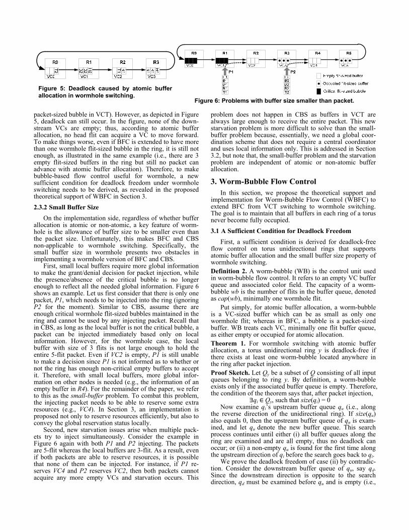
packet-sized bubble in VCT). However, as depicted in Figure 5, deadlock can still occur. In the figure, none of the down-stream VCs are empty; thus, according to atomic buffer allocation, no head flit can acquire a VC to move forward. To make things worse, even if BFC is extended to have more than one wormhole flit-sized bubble in the ring, it is still not enough, as illustrated in the same example (i.e., there are 3 empty flit-sized buffers in the ring but still no packet can advance with atomic buffer allocation). Therefore, to make bubble-based flow control useful for wormhole, a new sufficient condition for deadlock freedom under wormhole switching needs to be derived, as revealed in the proposed theoretical support of WBFC in Section 3. 2.3.2 Small Buffer Size
On the implementation side, regardless of whether buffer allocation is atomic or non-atomic, a key feature of worm-hole is the allowance of buffer size to be smaller even than the packet size. Unfortunately, this makes BFC and CBS non-applicable to wormhole switching. Specifically, the small buffer size in wormhole presents two obstacles in implementing a wormhole version of BFC and CBS.
First, small local buffers require more global information to make the grant/denial decision for packet injection, while the presence/absence of the critical bubble is no longer enough to reflect all the needed global information. Figure 6 shows an example. Let us first consider that there is only one packet, P1, which needs to be injected into the ring (ignoring P2 for the moment). Similar to CBS, assume there are enough critical wormhole flit-sized bubbles maintained in the ring and cannot be used by any injecting packet. Recall that in CBS, as long as the local buffer is not the critical bubble, a packet can be injected immediately based only on local information. However, for the wormhole case, the local buffer with size of 3 flits is not large enough to hold the entire 5-flit packet. Even if VC2 is empty, P1 is still unable to make a decision since P1 is not informed as to whether or not the ring has enough non-critical empty buffers to accept it. Therefore, with small local buffers, more global infor-mation on other nodes is needed (e.g., the information of an empty buffer in R4). For the remainder of the paper, we refer to this as the small-buffer problem. To combat this problem, the injecting packet needs to be able to reserve some extra resources (e.g., VC4). In Section 3, an implementation is proposed not only to reserve resources efficiently, but also to convey the global reservation status locally.
Second, new starvation issues arise when multiple pack-ets try to inject simultaneously. Consider the example in Figure 6 again with both P1 and P2 injecting. The packets are 5-flit whereas the local buffers are 3-flit. As a result, even if both packets are able to reserve resources, it is possible that none of them can be injected. For instance, if P1 re-serves VC4 and P2 reserves VC2, then both packets cannot acquire any more empty VCs and starvation occurs. This
problem does not happen in CBS as buffers in VCT are always large enough to receive the entire packet. This new starvation problem is more difficult to solve than the small-buffer problem because, essentially, we need a global coor-dination scheme that does not require a central coordinator and uses local information only. This is addressed in Section 3.2, but note that, the small-buffer problem and the starvation problem are independent of atomic or non-atomic buffer allocation.
3. Worm-Bubble Flow Control In this section, we propose the theoretical support and
implementation for Worm-Bubble Flow Control (WBFC) to extend BFC from VCT switching to wormhole switching. The goal is to maintain that all buffers in each ring of a torus never become fully occupied. 3.1 A Sufficient Condition for Deadlock Freedom
First, a sufficient condition is derived for deadlock-free flow control on torus unidirectional rings that supports atomic buffer allocation and the small buffer size property of wormhole switching. Definition 2. A worm-bubble (WB) is the control unit used in worm-bubble flow control. It refers to an empty VC buffer queue and associated color field. The capacity of a worm-bubble wb is the number of flits in the buffer queue, denoted as cap(wb), minimally one wormhole flit.
Put simply, for atomic buffer allocation, a worm-bubble is a VC-sized buffer which can be as small as only one wormhole flit; whereas in BFC, a bubble is a packet-sized buffer. WB treats each VC, minimally one flit buffer queue, as either empty or occupied for atomic allocation. Theorem 1. For wormhole switching with atomic buffer allocation, a torus unidirectional ring y is deadlock-free if there exists at least one worm-bubble located anywhere in the ring after packet injection. Proof Sketch. Let Qy be a subset of Q consisting of all input queues belonging to ring y. By definition, a worm-bubble exists only if the associated buffer queue is empty. Therefore, the condition of the theorem says that, after packet injection, ∃qi ∈ Qy, such that size(qi) = 0
Now examine qi’s upstream buffer queue qu (i.e., along the reverse direction of the unidirectional ring). If size(qu) also equals 0, then the upstream buffer queue of qu is exam-ined, and let qu denote the new buffer queue. This search process continues until either (i) all buffer queues along the ring are examined and are all empty, thus no deadlock can occur; or (ii) a non-empty qu is found for the first time along the upstream direction of qi before the search goes back to qi.
We prove the deadlock freedom of case (ii) by contradic-tion. Consider the downstream buffer queue of qu, say qd. Since the downstream direction is opposite to the search direction, qd must be examined before qu and is empty (i.e.,
Figure 5: Deadlock caused by atomic buffer allocation in wormhole switching.
Figure 6: Problems with buffer size smaller than packet.
size(qd) = 0). Now assume that there is a deadlock in the ring, so that no packet can make progress. In particular, the flit f at the head of qu cannot move into downstream buffer queue qd. However, if this f is a body or tail flit, it can advance to qd as long as size(qd) < cap(qd), which is currently satisfied as size(qd) = 0; otherwise, if f is a head flit, atomic buffer allocation requires that f can advance to qd only if size(qd) = 0, which is also satisfied by qd. Therefore, in either case the flit f can advance, contrary to the assumption that there is a deadlock configuration.
Considering both (i) and (ii), each unidirectional ring is guaranteed to be deadlock-free if there exists at least one worm-bubble anywhere in the ring. □
The theoretical support for WBFC proposed here is a sig-nificant extension of BFC from the VCT domain to the wormhole domain. As long as the packet injection process maintains the existence of a WB in the ring, together with DOR, WBFC can achieve deadlock-free routing in worm-hole-switched tori using only one VC. 3.2 Worm-Bubble Flow Control Implementation
To maintain the existence of a worm-bubble after single and simultaneous packet injection1, WBFC implementation schemes (particularly those that use local information only) need to solve the small-buffer problem and the starvation problem caused by insufficient global information. 3.2.1 Combating the Small-buffer Problem
We first discuss how to overcome the small-buffer prob-lem that occurs under single packet injection. Since this problem is caused by the small local buffer size, extra buffers located elsewhere in the ring are needed for a packet to inject. The basic idea of the proposed WBFC scheme is first to reserve (mark) some additional buffers in the ring for an injecting packet and then, after the packet is injected and traversing along the ring, progressively unmark the previous-ly reserved buffers, thereby freeing buffers so that they can be used by other injecting packets.
To achieve that, WBs are marked as either white or black. The white WBs are normal empty buffer queues that can be used by any packet, whereas the black ones can only be used by in-transit packets. Similar to CBS, the black WBs can be displaced backward in the ring either proactively (e.g., if the upstream WB is white and there is a packet waiting to access the black WB), or by the in-transit packet that occupies it (i.e., black WB is transferred backwards). The initial colors of WBs are all white.
For the convenience of this discussion, a quantity M is defined for each packet as below, which is useful for mark-ing buffers. Definition 3. The M value of a packet p represents the minimal number of worm-bubbles needed to receive the packet into a ring, denoted as Mp. That is,
Mp = ⌈ L(p) / cap(wb) ⌉ For example, if a long packet p is 5-flit long and the WB
is 3-flit large, then Mp = ⌈5/3⌉ = 2, meaning that it takes 2 WBs to receive the injecting packet. In case of short packets, say 1-flit-sized, then Mp = ⌈1/3⌉ = 1. Additionally, in what follows, packets that are already completely injected and
1 Injection includes initial injection by the local node as well as changing from one dimension into another.
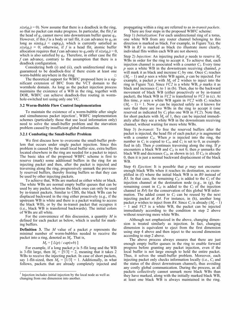
propagating within a ring are referred to as in-transit packets. There are four steps in the proposed WBFC scheme:
Step 1) Initialization: For each unidirectional ring of a torus, one white WB from any router channel belonging to this direction is marked as black. For example, in Figure 7(a), the WB in R3 is marked as black (to illustrate more clearly, individual flits within each WB are not shown). Step 2) Injection: An injecting packet p needs to reserve Mp WBs in order for the ring to accept it. To achieve that, each injection channel is associated with a counter CI. Every time p sees a white WB in the downstream receiving channel, p will mark it as black and increase CI by one. Once CI reaches (Mp – 1) and p sees a white WB again, p can be injected. For example, a packet p with Mp of 2 wishes to inject into the ring in Figure 7(a). Since VC2 is a white WB, p marks it as black and increases CI to 1 in (b). Then, due to the backward movement of black WB (either proactively or by in-transit packet), the black WB in VC2 is transferred to VC1 in (c). At this time, p sees a white WB again in VC2 with CI reaches (Mp – 1) = 1. Now p can be injected safely as it knows for sure that there are two WBs in the ring to accept it (one reserved as indicated by CI plus one WB in VC2). Note that, for short packets with Mp of 1, they can be injected immedi-ately after they see a white WB in the downstream receiving channel, without waiting for more white WBs. Step 3) In-transit: To free the reserved buffers after the packet is injected, the head flit of each packet p is augmented with a counter CH. When p is injected into the ring, the number in CI is copied to CH, and CI is set to 0, as exempli-fied in (d). Then p continues traversing along the ring. If p encounters a black WB and CH is not 0, then p unmarks the black WB and decreases CH, as shown in (e). If CH is already 0, then it is just a normal backward displacement of the black WB. Step 4) Ejection: It is possible that p may not encounter enough black WBs when it reaches its destination, as exem-plified in (f) where the initial black WB is in R0 instead of R3. In that case, the remaining CH is added to the CI of the injection channel at the destination node (e.g., in (g), the remaining count in CH is added to the CI of the injection channel in R4) for the conservation of this global WB infor-mation. The added count to CI can be reused by the next injecting packet at R4. For instance, in (h), another long packet p wishes to inject from R4. Since CI is already (Mp – 1) = 1 and VC5 is a white WB, the packet can be injected immediately according to the condition in step 2 above without reserving more white WBs.
Although not emphasized in the above, changing dimen-sion is treated similarly as injection. In fact, changing dimension is equivalent to eject from the first dimension using step 4 above and then inject to the second dimension according to step 2 above.
The above process always ensures that there are just enough empty buffer queues in the ring to enable forward progress before granting any packet injection, even if the local buffer is not large enough to hold the entire packet. Thus, it solves the small-buffer problem. Moreover, each injecting packet only checks information locally (i.e., CI and the status of the direct downstream channel), thus avoiding any costly global communication. During the process, as all packets collectively cannot unmark more black WBs than they have marked, along with the initially marked black WB, at least one black WB is always maintained in the ring.
According to Theorem 1, the ring is deadlock-free. A proof sketch of the deadlock freedom is provided in Section 3.4. 3.2.2 Combating the Starvation Problem
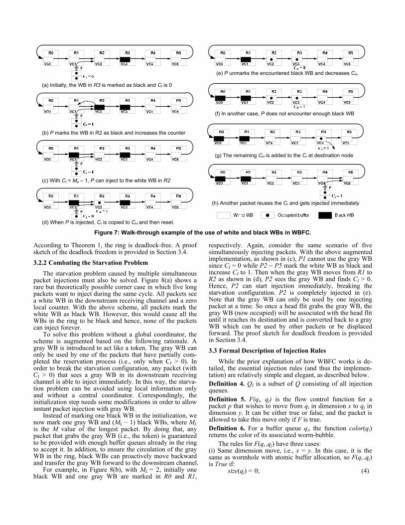
The starvation problem caused by multiple simultaneous packet injections must also be solved. Figure 8(a) shows a rare but theoretically possible corner case in which five long packets want to inject during the same cycle. All packets see a white WB in the downstream receiving channel and a zero local counter. With the above scheme, all packets mark the white WB as black WB. However, this would cause all the WBs in the ring to be black and hence, none of the packets can inject forever.
To solve this problem without a global coordinator, the scheme is augmented based on the following rationale. A gray WB is introduced to act like a token. The gray WB can only be used by one of the packets that have partially com-pleted the reservation process (i.e., only when CI > 0). In order to break the starvation configuration, any packet (with CI > 0) that sees a gray WB in its downstream receiving channel is able to inject immediately. In this way, the starva-tion problem can be avoided using local information only and without a central coordinator. Correspondingly, the initialization step needs some modifications in order to allow instant packet injection with gray WB.
Instead of marking one black WB in the initialization, we now mark one gray WB and (ML – 1) black WBs, where ML is the M value of the longest packet. By doing that, any packet that grabs the gray WB (i.e., the token) is guaranteed to be provided with enough buffer queues already in the ring to accept it. In addition, to ensure the circulation of the gray WB in the ring, black WBs can proactively move backward and transfer the gray WB forward to the downstream channel.
For example, in Figure 8(b), with ML = 2, initially one black WB and one gray WB are marked in R0 and R1,
respectively. Again, consider the same scenario of five simultaneously injecting packets. With the above augmented implementation, as shown in (c), P1 cannot use the gray WB since CI = 0 while P2 ~ P5 mark the white WB as black and increase CI to 1. Then when the gray WB moves from R1 to R2 as shown in (d), P2 sees the gray WB and finds CI > 0. Hence, P2 can start injection immediately, breaking the starvation configuration. P2 is completely injected in (e). Note that the gray WB can only be used by one injecting packet at a time. So once a head flit grabs the gray WB, the gray WB (now occupied) will be associated with the head flit until it reaches its destination and is converted back to a gray WB which can be used by other packets or be displaced forward. The proof sketch for deadlock freedom is provided in Section 3.4. 3.3 Formal Description of Injection Rules
While the prior explanation of how WBFC works is de-tailed, the essential injection rules (and thus the implemen-tation) are relatively simple and elegant, as described below. Definition 4. QI is a subset of Q consisting of all injection queues. Definition 5. F(qi, qj) is the flow control function for a packet p that wishes to move from qi in dimension x to qj in dimension y. It can be either true or false, and the packet is allowed to take this move only if F is true. Definition 6. For a buffer queue qi, the function color(qi) returns the color of its associated worm-bubble.
The rules for F(qi ,qj) have three cases: (i) Same dimension move, i.e., x = y. In this case, it is the same as wormhole with atomic buffer allocation, so F(qi ,qj) is True if:
size(qj) = 0; (4)
Figure 7: Walk-through example of the use of white and black WBs in WBFC.
(a) Initially, the WB in R3 is marked as black and CI is 0
(b) P marks the WB in R2 as black and increases the counter
(c) With CI = Mp – 1, P can inject to the white WB in R2
(d) When P is injected, CI is copied to CH and then reset.
(e) P unmarks the encountered black WB and decreases CH.
(h) Another packet reuses the CI and gets injected immediately
(f) In another case, P does not encounter enough black WB
(g) The remaining CH is added to the CI at destination node
(ii) Short packet injection or changing dimension, i.e., Mp = 1 and qi ∈ QI ∨ x ≠ y. In this case, F(qi ,qj) is True if:
size(qj) = 0 ∧ color(qj) ≠ black; (5) (iii) Long packet injection or changing dimension, i.e., Mp > 1 and qi ∈ QI ∨ x ≠ y. In this case, F(qi ,qj) is True if:
size(qj) = 0 ∧ color(qj) = white ∧ CI ≥ Mp – 1, or size(qj) = 0 ∧ color(qj) = gray ∧ CI > 0 (6)
The above F(qi ,qj) of WBFC together with DOR can re-alize deadlock-free deterministic routing using only one VC. To achieve adaptive routing, similar to BFC and CBS, this one VC acts as an escape resource and more VCs can be added as adaptive resources. The rules of WBFC apply only when packets wish to enter from adaptive VCs to escape VCs and inject/change dimension in escape VCs (i.e., to keep the escape resource deadlock-free). Packets on adaptive VCs can inject or change dimension freely without being restricted by WBFC. 3.4 Deadlock Freedom of WBFC Lemma 1. Worm-bubble flow control is deadlock-free for each unidirectional ring of a torus. Proof Sketch. Consider an arbitrary unidirectional ring y of a torus. We prove that, in each of the following possible cases, there exists a WB in the ring after packet injection. Case (i) The maximum ML = 1. This means that all packets are short and, initially, 1 gray WB is marked. Since CI = Mp – 1 is always 0 for short packets, the gray WB can never be used during packet injection according to Equation (6). Thus, an empty gray WB always exists in ring y (as all packets are short, this case is equivalent to CBS). Case (ii) ML > 1 and a packet p uses a gray WB during injection. Consider the number of black and gray WBs in ring y. Initially, there are at least 1 gray WB and (ML – 1) black WBs. A packet that uses a gray WB to inject must have CI ≥ 1, meaning that it must have marked at least one 1 more black WB. Consequently, there are at least 1 gray and ML black WBs in the ring before injection, and p consumes at most 1 gray and (ML – 1) WB. Therefore, at least one black WB remains in ring y after the injection. The gray WB cannot be used by other packets until p reaches the destina-tion, at which point, the consumed WBs will be released to
maintain the WB counts. Case (iii) ML > 1 and a packet p only uses black and white WBs during injection. In this case, before injection, p has reserved at least (Mp – 1) black WBs and there is a white WB in the receiving channel. The injection of p can at most consume all these WBs. Hence the initially marked WBs are not touched, which includes at least (ML – 1) ≥ 1 black WBs in ring y. Combining cases (i)~(iii), there always exists a black or gray WB in ring y after packet injection. According to Theorem 1, ring y is deadlock-free. As y is selected arbitrarily, each ring of a torus is deadlock-free. □ 3.5 Reducing Injection Delay
As with all bubble-based flow control mechanisms, a concern is whether the flow control technique causes a large delay in packet injection. For example, packets in WBFC need to wait for white or gray WBs before being able to inject. However, there are five features in WBFC that can substantially mitigate the increase in injection delay.
First, as just mentioned above, packets on adaptive VCs are not subjected to the added rules, so they have no extra delay. Second, short packets with Mp of 1 can be injected immediately after they see a white WB; only long packets need to wait for non-local white WBs. Third, similar to CBS, idle white and gray WBs are proactively displaced to reduce the waiting time of packets in need. Fourth, the gray WB not only serves as a starvation-avoidance token, but can also accelerate packet injection, as packets that are qualified for grabbing the gray WB can be injected immediately even if CI has not reached (Mp – 1). Fifth, when packets arrive at the destination node, the remaining counts in CH are passed on to the destination CI so that later injecting packets can reuse the already marked WB, thereby reducing the injection time. Due to these reasons, WBFC only incurs minimal increase in injection delay, as shown in evaluation (Section 5). 3.6 Modifications to Router Microarchitecture
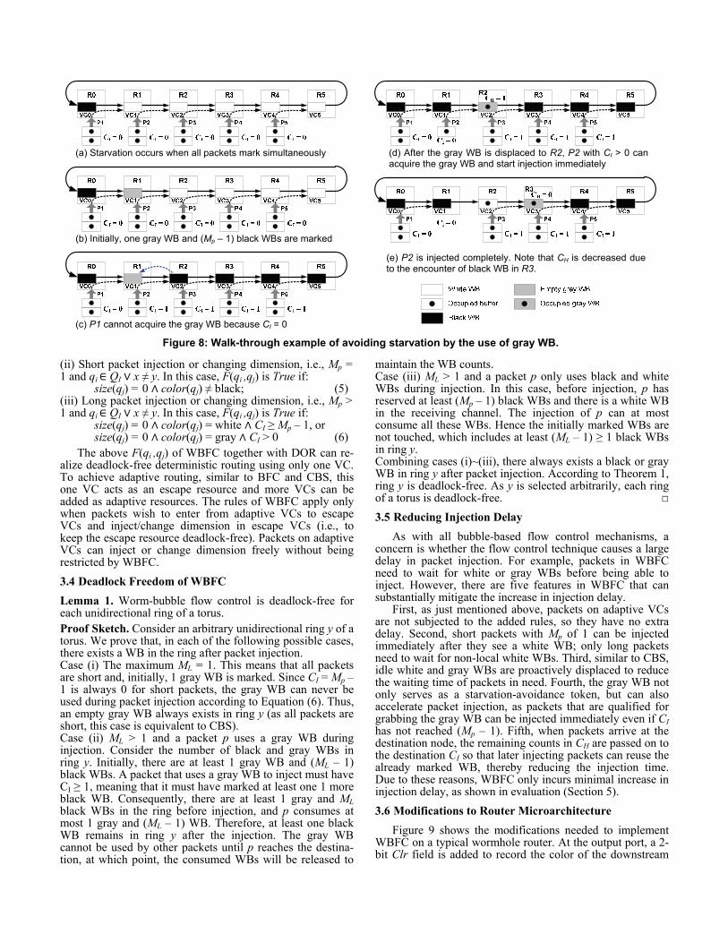
Figure 9 shows the modifications needed to implement WBFC on a typical wormhole router. At the output port, a 2-bit Clr field is added to record the color of the downstream
Figure 8: Walk-through example of avoiding starvation by the use of gray WB.
(a) Starvation occurs when all packets mark simultaneously
(b) Initially, one gray WB and (Mp – 1) black WBs are marked
(c) P1 cannot acquire the gray WB because CI = 0
(d) After the gray WB is displaced to R2, P2 with CI > 0 can acquire the gray WB and start injection immediately
(e) P2 is injected completely. Note that CH is decreased due to the encounter of black WB in R3.
WB, and the CI field is added to count the number of re-served/marked WBs for an injection channel. The counter is used whenever packets need to inject (or change dimension) into the escape VC from the injection queue or from adaptive VCs. To avoid the WBs in a unidirectional ring from being overly reserved, the counter is shared by all injection sources to an output direction. The injection source that wins the VA/SA will use the counter until the packet marks enough WBs and gets injected (note that the in-transit packets can still use the output when the injecting packet is waiting for a white WB). The number of bits of the CI field is ⌈log k⌉, assuming k nodes in a ring. In addition, only the escape VC needs Clr and CI, therefore the overhead for the extra two fields is only 4 bits (for 4x4 torus) or 5 bits (for 8x8 torus) per output port.
To support the rules of WBFC, VA logic is slightly modi-fied based on Equations (4)~(6). However, two things are worth mentioning: (i) the logic needed to implement (4)~(6) is no more than a few comparators and AND/OR gates, hence the hardware overhead is small; (ii) the added logic operates largely in parallel with the original VA logic (e.g., the checking of WB color and counter in WBFC is per-formed while the original VA is checking the emptiness of the VC), thus it does not penalize the router critical path.
To control the WB transfer between routers, three control signals (wbt_a, wbt_b and wb_clr) are added. When the black WB in the downstream router needs to be transferred backwards (either proactively or due to incoming packets), wbt_a is asserted to request a color transfer to the upstream router. Upon detecting the asserted wbt_a, if there is a free white/gray WB in the upstream router, then the upstream router asserts the wbt_b signal, puts the white/gray color on the wb_clr line, and changes the current WB color to black. When the downstream router sees an asserted wbt_b, it changes the black WB to white/gray color. Finally, the wbt_a and wbt_b signals are deasserted, in turn, to complete the color transfer.
4. Evaluation Methodology The proposed WBFC is evaluated experimentally under
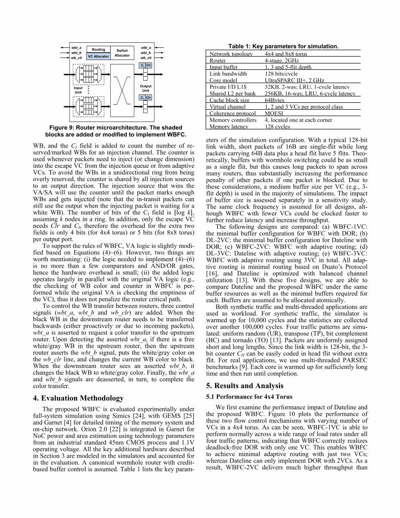
full-system simulation using Simics [24], with GEMS [25] and Garnet [4] for detailed timing of the memory system and on-chip network. Orion 2.0 [22] is integrated in Garnet for NoC power and area estimation using technology parameters from an industrial standard 45nm CMOS process and 1.1V operating voltage. All the key additional hardware described in Section 3 are modeled in the simulators and accounted for in the evaluation. A canonical wormhole router with credit-based buffer control is assumed. Table 1 lists the key param-
eters of the simulation configuration. With a typical 128-bit link width, short packets of 16B are single-flit while long packets carrying 64B data plus a head flit have 5 flits. Theo-retically, buffers with wormhole switching could be as small as a single flit, but this causes long packets to span across many routers, thus substantially increasing the performance penalty of other packets if one packet is blocked. Due to these considerations, a medium buffer size per VC (e.g., 3-flit depth) is used in the majority of simulations. The impact of buffer size is assessed separately in a sensitivity study. The same clock frequency is assumed for all designs, alt-hough WBFC with fewer VCs could be clocked faster to further reduce latency and increase throughput.
The following designs are compared: (a) WBFC-1VC: the minimal buffer configuration for WBFC with DOR; (b) DL-2VC: the minimal buffer configuration for Dateline with DOR; (c) WBFC-2VC: WBFC with adaptive routing; (d) DL-3VC: Dateline with adaptive routing; (e) WBFC-3VC: WBFC with adaptive routing using 3VC in total. All adap-tive routing is minimal routing based on Duato’s Protocol [16], and Dateline is optimized with balanced channel utilization [13]. With these five designs, we are able to compare Dateline and the proposed WBFC under the same buffer resources as well as the minimal buffers required for each. Buffers are assumed to be allocated atomically.
Both synthetic traffic and multi-threaded applications are used as workload. For synthetic traffic, the simulator is warmed up for 10,000 cycles and the statistics are collected over another 100,000 cycles. Four traffic patterns are simu-lated: uniform random (UR), transpose (TP), bit complement (BC) and tornado (TO) [13]. Packets are uniformly assigned short and long lengths. Since the link width is 128-bit, the 3-bit counter CH can be easily coded in head flit without extra flit. For real applications, we use multi-threaded PARSEC benchmarks [9]. Each core is warmed up for sufficiently long time and then run until completion.
5. Results and Analysis 5.1 Performance for 4x4 Torus
We first examine the performance impact of Dateline and the proposed WBFC. Figure 10 plots the performance of these two flow control mechanisms with varying number of VCs in a 4x4 torus. As can be seen, WBFC-1VC is able to perform normally across a wide range of load rates under all four traffic patterns, indicating that WBFC correctly realizes deadlock-free DOR with only one VC. This enables WBFC to achieve minimal adaptive routing with just two VCs; whereas Dateline can only implement DOR with 2VCs. As a result, WBFC-2VC delivers much higher throughput than
Figure 9: Router microarchitecture. The shaded blocks are added or modified to implement WBFC.
CI Clr
CI Clr
····
Input Unit
VC Allocator Switch
Allocator Routing
Output Unit
wbt_a wbt_b wb_clr
wbt_a wbt_b wb_clr
Table 1: Key parameters for simulation. Network topology 4x4 and 8x8 torus Router 4-stage, 2GHz Input buffer 1, 3 and 5-flit depth Link bandwidth 128 bits/cycle Core model UltraSPARC III+, 2 GHzPrivate I/D L1$ 32KB, 2-way, LRU, 1-cycle latencyShared L2 per bank 256KB, 16-way, LRU, 6-cycle latencyCache block size 64Bytes Virtual channel 1, 2 and 3 VCs per protocol classCoherence protocol MOESI Memory controllers 4, located one at each cornerMemory latency 128 cycles
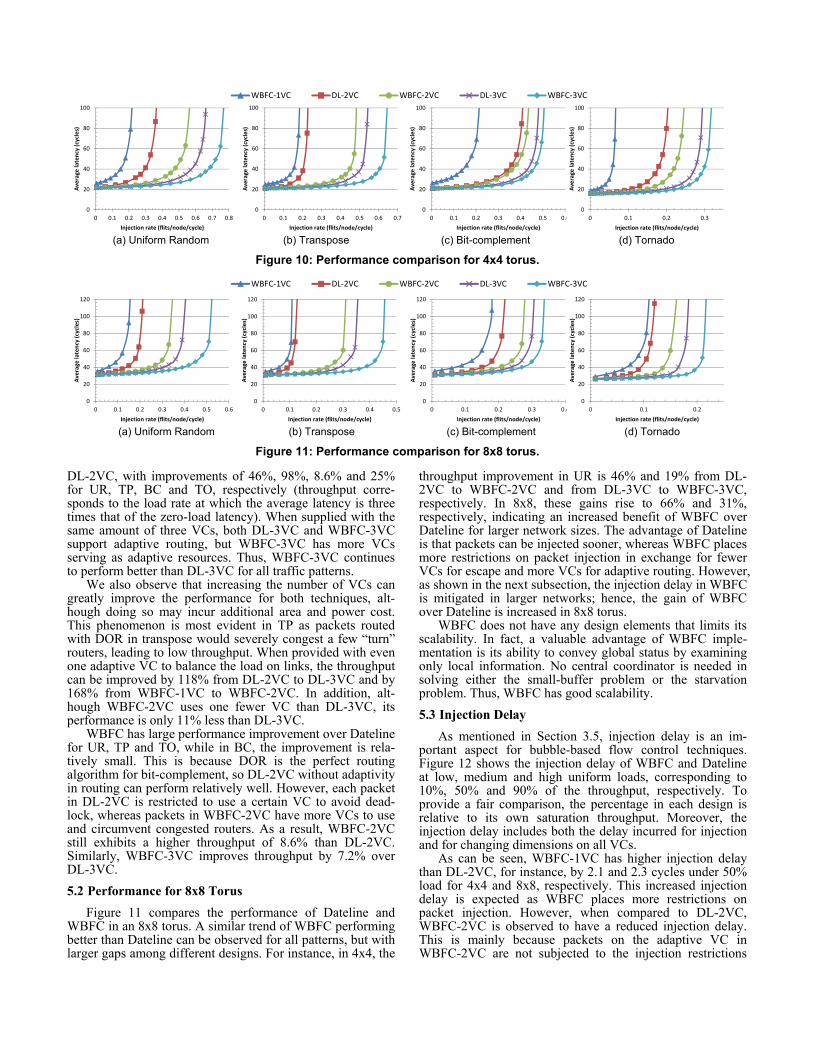
DL-2VC, with improvements of 46%, 98%, 8.6% and 25% for UR, TP, BC and TO, respectively (throughput corre-sponds to the load rate at which the average latency is three times that of the zero-load latency). When supplied with the same amount of three VCs, both DL-3VC and WBFC-3VC support adaptive routing, but WBFC-3VC has more VCs serving as adaptive resources. Thus, WBFC-3VC continues to perform better than DL-3VC for all traffic patterns.
We also observe that increasing the number of VCs can greatly improve the performance for both techniques, alt-hough doing so may incur additional area and power cost. This phenomenon is most evident in TP as packets routed with DOR in transpose would severely congest a few “turn” routers, leading to low throughput. When provided with even one adaptive VC to balance the load on links, the throughput can be improved by 118% from DL-2VC to DL-3VC and by 168% from WBFC-1VC to WBFC-2VC. In addition, alt-hough WBFC-2VC uses one fewer VC than DL-3VC, its performance is only 11% less than DL-3VC. WBFC has large performance improvement over Dateline for UR, TP and TO, while in BC, the improvement is rela-tively small. This is because DOR is the perfect routing algorithm for bit-complement, so DL-2VC without adaptivity in routing can perform relatively well. However, each packet in DL-2VC is restricted to use a certain VC to avoid dead-lock, whereas packets in WBFC-2VC have more VCs to use and circumvent congested routers. As a result, WBFC-2VC still exhibits a higher throughput of 8.6% than DL-2VC. Similarly, WBFC-3VC improves throughput by 7.2% over DL-3VC. 5.2 Performance for 8x8 Torus
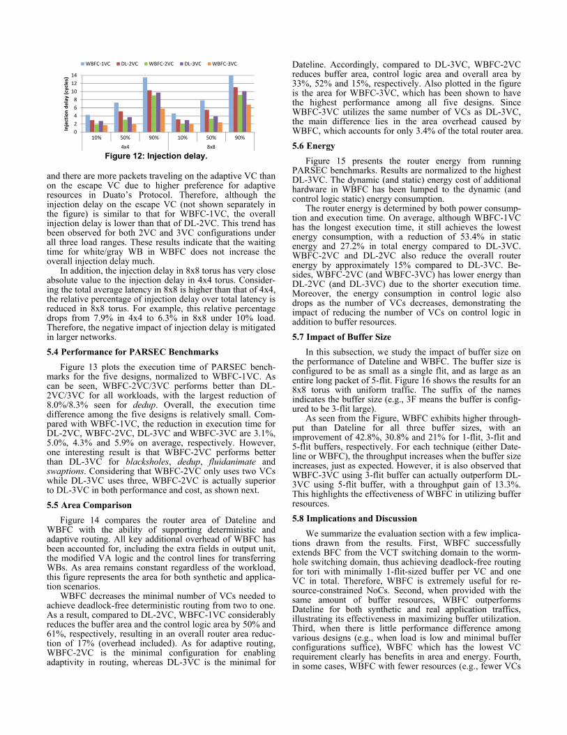
Figure 11 compares the performance of Dateline and WBFC in an 8x8 torus. A similar trend of WBFC performing better than Dateline can be observed for all patterns, but with larger gaps among different designs. For instance, in 4x4, the
throughput improvement in UR is 46% and 19% from DL-2VC to WBFC-2VC and from DL-3VC to WBFC-3VC, respectively. In 8x8, these gains rise to 66% and 31%, respectively, indicating an increased benefit of WBFC over Dateline for larger network sizes. The advantage of Dateline is that packets can be injected sooner, whereas WBFC places more restrictions on packet injection in exchange for fewer VCs for escape and more VCs for adaptive routing. However, as shown in the next subsection, the injection delay in WBFC is mitigated in larger networks; hence, the gain of WBFC over Dateline is increased in 8x8 torus.
WBFC does not have any design elements that limits its scalability. In fact, a valuable advantage of WBFC imple-mentation is its ability to convey global status by examining only local information. No central coordinator is needed in solving either the small-buffer problem or the starvation problem. Thus, WBFC has good scalability. 5.3 Injection Delay
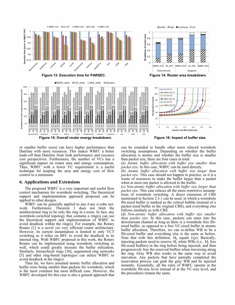
As mentioned in Section 3.5, injection delay is an im-portant aspect for bubble-based flow control techniques. Figure 12 shows the injection delay of WBFC and Dateline at low, medium and high uniform loads, corresponding to 10%, 50% and 90% of the throughput, respectively. To provide a fair comparison, the percentage in each design is relative to its own saturation throughput. Moreover, the injection delay includes both the delay incurred for injection and for changing dimensions on all VCs.
As can be seen, WBFC-1VC has higher injection delay than DL-2VC, for instance, by 2.1 and 2.3 cycles under 50% load for 4x4 and 8x8, respectively. This increased injection delay is expected as WBFC places more restrictions on packet injection. However, when compared to DL-2VC, WBFC-2VC is observed to have a reduced injection delay. This is mainly because packets on the adaptive VC in WBFC-2VC are not subjected to the injection restrictions
Figure 10: Performance comparison for 4x4 torus.
0
20
40
60
80
100
0 0.1 0.2 0.3 0.4 0.5 0.6 0.7 0.8
Aver
age
late
ncy
(cyc
les)
Injection rate (flits/node/cycle)
0
20
40
60
80
100
0 0.1 0.2 0.3 0.4 0.5 0.6 0.7
Aver
age
late
ncy
(cyc
les)
Injection rate (flits/node/cycle)
0
20
40
60
80
100
0 0.1 0.2 0.3 0.4 0.5 0.6
Aver
age
late
ncy
(cyc
les)
Injection rate (flits/node/cycle)
0
20
40
60
80
100
0 0.1 0.2 0.3
Aver
age
late
ncy
(cyc
les)
Injection rate (flits/node/cycle)
WBFC-1VC DL-2VC WBFC-2VC DL-3VC WBFC-3VC
(a) Uniform Random (b) Transpose (c) Bit-complement (d) Tornado
0
20
40
60
80
100
120
0 0.1 0.2 0.3 0.4 0.5 0.6
Aver
age
late
ncy
(cyc
les)
Injection rate (flits/node/cycle)
0
20
40
60
80
100
120
0 0.1 0.2 0.3 0.4 0.5
Aver
age
late
ncy
(cyc
les)
Injection rate (flits/node/cycle)
0
20
40
60
80
100
120
0 0.1 0.2 0.3 0.4Av
erag
e la
tenc
y (c
ycle
s)Injection rate (flits/node/cycle)
0
20
40
60
80
100
120
0 0.1 0.2
Aver
age
late
ncy
(cyc
les)
Injection rate (flits/node/cycle)
WBFC-1VC DL-2VC WBFC-2VC DL-3VC WBFC-3VC
(a) Uniform Random (b) Transpose (c) Bit-complement (d) Tornado
Figure 11: Performance comparison for 8x8 torus.
and there are more packets traveling on the adaptive VC than on the escape VC due to higher preference for adaptive resources in Duato’s Protocol. Therefore, although the injection delay on the escape VC (not shown separately in the figure) is similar to that for WBFC-1VC, the overall injection delay is lower than that of DL-2VC. This trend has been observed for both 2VC and 3VC configurations under all three load ranges. These results indicate that the waiting time for white/gray WB in WBFC does not increase the overall injection delay much.
In addition, the injection delay in 8x8 torus has very close absolute value to the injection delay in 4x4 torus. Consider-ing the total average latency in 8x8 is higher than that of 4x4, the relative percentage of injection delay over total latency is reduced in 8x8 torus. For example, this relative percentage drops from 7.9% in 4x4 to 6.3% in 8x8 under 10% load. Therefore, the negative impact of injection delay is mitigated in larger networks. 5.4 Performance for PARSEC Benchmarks
Figure 13 plots the execution time of PARSEC bench-marks for the five designs, normalized to WBFC-1VC. As can be seen, WBFC-2VC/3VC performs better than DL-2VC/3VC for all workloads, with the largest reduction of 8.0%/8.3% seen for dedup. Overall, the execution time difference among the five designs is relatively small. Com-pared with WBFC-1VC, the reduction in execution time for DL-2VC, WBFC-2VC, DL-3VC and WBFC-3VC are 3.1%, 5.0%, 4.3% and 5.9% on average, respectively. However, one interesting result is that WBFC-2VC performs better than DL-3VC for blacksholes, dedup, fluidanimate and swaptions. Considering that WBFC-2VC only uses two VCs while DL-3VC uses three, WBFC-2VC is actually superior to DL-3VC in both performance and cost, as shown next. 5.5 Area Comparison
Figure 14 compares the router area of Dateline and WBFC with the ability of supporting deterministic and adaptive routing. All key additional overhead of WBFC has been accounted for, including the extra fields in output unit, the modified VA logic and the control lines for transferring WBs. As area remains constant regardless of the workload, this figure represents the area for both synthetic and applica-tion scenarios.
WBFC decreases the minimal number of VCs needed to achieve deadlock-free deterministic routing from two to one. As a result, compared to DL-2VC, WBFC-1VC considerably reduces the buffer area and the control logic area by 50% and 61%, respectively, resulting in an overall router area reduc-tion of 17% (overhead included). As for adaptive routing, WBFC-2VC is the minimal configuration for enabling adaptivity in routing, whereas DL-3VC is the minimal for
Dateline. Accordingly, compared to DL-3VC, WBFC-2VC reduces buffer area, control logic area and overall area by 33%, 52% and 15%, respectively. Also plotted in the figure is the area for WBFC-3VC, which has been shown to have the highest performance among all five designs. Since WBFC-3VC utilizes the same number of VCs as DL-3VC, the main difference lies in the area overhead caused by WBFC, which accounts for only 3.4% of the total router area. 5.6 Energy
Figure 15 presents the router energy from running PARSEC benchmarks. Results are normalized to the highest DL-3VC. The dynamic (and static) energy cost of additional hardware in WBFC has been lumped to the dynamic (and control logic static) energy consumption.
The router energy is determined by both power consump-tion and execution time. On average, although WBFC-1VC has the longest execution time, it still achieves the lowest energy consumption, with a reduction of 53.4% in static energy and 27.2% in total energy compared to DL-3VC. WBFC-2VC and DL-2VC also reduce the overall router energy by approximately 15% compared to DL-3VC. Be-sides, WBFC-2VC (and WBFC-3VC) has lower energy than DL-2VC (and DL-3VC) due to the shorter execution time. Moreover, the energy consumption in control logic also drops as the number of VCs decreases, demonstrating the impact of reducing the number of VCs on control logic in addition to buffer resources. 5.7 Impact of Buffer Size
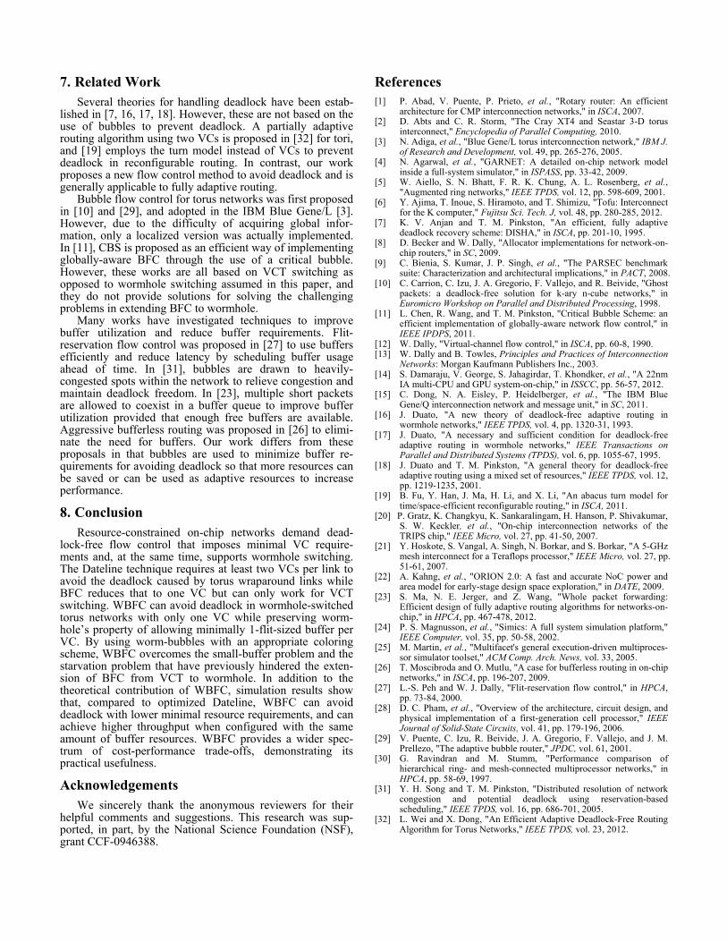
In this subsection, we study the impact of buffer size on the performance of Dateline and WBFC. The buffer size is configured to be as small as a single flit, and as large as an entire long packet of 5-flit. Figure 16 shows the results for an 8x8 torus with uniform traffic. The suffix of the names indicates the buffer size (e.g., 3F means the buffer is config-ured to be 3-flit large).
As seen from the Figure, WBFC exhibits higher through-put than Dateline for all three buffer sizes, with an improvement of 42.8%, 30.8% and 21% for 1-flit, 3-flit and 5-flit buffers, respectively. For each technique (either Date-line or WBFC), the throughput increases when the buffer size increases, just as expected. However, it is also observed that WBFC-3VC using 3-flit buffer can actually outperform DL-3VC using 5-flit buffer, with a throughput gain of 13.3%. This highlights the effectiveness of WBFC in utilizing buffer resources. 5.8 Implications and Discussion
We summarize the evaluation section with a few implica-tions drawn from the results. First, WBFC successfully extends BFC from the VCT switching domain to the worm-hole switching domain, thus achieving deadlock-free routing for tori with minimally 1-flit-sized buffer per VC and one VC in total. Therefore, WBFC is extremely useful for re-source-constrained NoCs. Second, when provided with the same amount of buffer resources, WBFC outperforms Dateline for both synthetic and real application traffics, illustrating its effectiveness in maximizing buffer utilization. Third, when there is little performance difference among various designs (e.g., when load is low and minimal buffer configurations suffice), WBFC which has the lowest VC requirement clearly has benefits in area and energy. Fourth, in some cases, WBFC with fewer resources (e.g., fewer VCs
02468
101214
10% 50% 90% 10% 50% 90%
4x4 8x8
Inje
ctio
n de
lay
(cyc
les)
WBFC-1VC DL-2VC WBFC-2VC DL-3VC WBFC-3VC
Figure 12: Injection delay.
or smaller buffer sizes) can have higher performance than Dateline with more resources. This makes WBFC a better trade-off than Dateline from both performance and resource cost perspectives. Furthermore, the number of VCs has a significant impact on router area and energy consumption. Thus, WBFC with a lower VC requirement is a useful technique for keeping the area and energy cost of flow control to a minimum.
6. Applications and Extensions The proposed WBFC is a very important and useful flow
control mechanism for wormhole switching. The theoretical support and implementation approach proposed can be applied to other designs.
WBFC can be generally applied to any k-ary n-cube net-work. Furthermore, Theorem 1 does not limit the unidirectional ring to be only the ring in a torus. In fact, any wormhole-switched topology that contains a ring(s) can use the theoretical support and implementation of WBFC to avoid deadlock within the ring(s). For example, the Rotary Router [1] is a novel yet very efficient router architecture. However, its current instantiation is limited to only VCT switching as it relies on BFC to avoid the deadlock in its internal ring. With WBFC proposed in this work, the Rotary Router can be implemented using wormhole switching as well, which could greatly increase the buffer utilization. Similarly, hierarchical rings [30], augmented ring networks [5] and other ring-based topologies can utilize WBFC to avoid deadlock in the ring(s).
Thus far, we have assumed atomic buffer allocation and buffer sizes being smaller than packets for wormhole, which is the most common but most difficult case. However, the WBFC developed for this case is also a general approach that
can be extended to handle other more relaxed wormhole switching assumptions. Depending on whether the buffer allocation is atomic and whether the buffer size is smaller than packet size, there are four cases in total: (a) Atomic buffer allocation with buffer size smaller than packet size. In this case, WBFC can be used directly. (b) Atomic buffer allocation with buffer size larger than packet size. This case should not happen in practice, as it is a waste of resources to make the buffer larger than a packet when at most one packet is allowed in the buffer. (c) Non-atomic buffer allocation with buffer size larger than packet size. This case relaxes all the more restrictive assump-tions of wormhole switching. A direct extension of CBS mentioned in Section 2.3.1 can be used, in which a wormhole flit-sized buffer is marked as the critical bubble (instead of a packet-sized buffer in the original CBS), and everything else follows similarly as with CBS. (d) Non-atomic buffer allocation with buffer size smaller than packet size. In this case, packets can enter into the downstream channel as long as there is a wormhole free flit-sized buffer, as opposed to a free VC-sized buffer in atomic buffer allocation. Therefore, we can re-define WB to be a flit-sized buffer and everything else is the same as before. Note that with this definition, Mp equals L(p). Basically, injecting packets need to reserve Mp white WBs (i.e., Mp free flit-sized buffers) in the ring before being injected, and then progressively free the reserved buffers when traversing along the ring. Gray WB also works in the same way to avoid starvation. Any packets that have partially completed the reservation process can grab the gray WB and be injected instantly. Essentially, all the rules of WBFC operate at the wormhole flit-size level instead of at the VC-size level, and the procedures remain the same.
0
20
40
60
80
100
120
0 0.1 0.2 0.3 0.4 0.5 0.6
Aver
age
late
ncy
(cyc
les)
Injection rate (flits/node/cycle)
DL-3VC-1F
WBFC-3VC-1F
DL-3VC-3F
WBFC-3VC-3F
DL-3VC-5F
WBFC-3VC-5F
Figure 13: Execution time for PARSEC.
Figure 15: Overall router energy breakdown.
Figure 14: Router area breakdown.
0%
20%
40%
60%
80%
100%
WBF
C-1V
CD
L-2V
CW
BFC-
2VC
DL-
3VC
WBF
C-3V
C
WBF
C-1V
CD
L-2V
CW
BFC-
2VC
DL-
3VC
WBF
C-3V
C
WBF
C-1V
CD
L-2V
CW
BFC-
2VC
DL-
3VC
WBF
C-3V
C
WBF
C-1V
CD
L-2V
CW
BFC-
2VC
DL-
3VC
WBF
C-3V
C
WBF
C-1V
CD
L-2V
CW
BFC-
2VC
DL-
3VC
WBF
C-3V
C
WBF
C-1V
CD
L-2V
CW
BFC-
2VC
DL-
3VC
WBF
C-3V
C
WBF
C-1V
CD
L-2V
CW
BFC-
2VC
DL-
3VC
WBF
C-3V
C
WBF
C-1V
CD
L-2V
CW
BFC-
2VC
DL-
3VC
WBF
C-3V
C
WBF
C-1V
CD
L-2V
CW
BFC-
2VC
DL-
3VC
WBF
C-3V
C
WBF
C-1V
CD
L-2V
CW
BFC-
2VC
DL-
3VC
WBF
C-3V
C
WBF
C-1V
CD
L-2V
CW
BFC-
2VC
DL-
3VC
WBF
C-3V
C
blackscholes bodytrack canneal dedup ferret fluidanimate raytrace swaptions vips x264 AVG
Brea
kdow
n of
rout
er e
nerg
y (n
orm
aliz
ed to
DL-
3VC)
Buffer_static Ctrl_static Xbar_static Dynamic
Figure 16: Impact of buffer size.
0
0.2
0.4
0.6
0.8
1
WBFC-1VC DL-2VC WBFC-2VC DL-3VC WBFC-3VC
Deterministic Adaptive
Brea
kdow
n of
rou
ter a
rea
buffer xbar overhead ctrl
0.75
0.8
0.85
0.9
0.95
1
Exec
utio
n tim
e (n
orm
. to
WBF
C-1V
C)WBFC-1VC DL-2VC WBFC-2VC DL-3VC WBFC-3VC
7. Related Work Several theories for handling deadlock have been estab-
lished in [7, 16, 17, 18]. However, these are not based on the use of bubbles to prevent deadlock. A partially adaptive routing algorithm using two VCs is proposed in [32] for tori, and [19] employs the turn model instead of VCs to prevent deadlock in reconfigurable routing. In contrast, our work proposes a new flow control method to avoid deadlock and is generally applicable to fully adaptive routing.
Bubble flow control for torus networks was first proposed in [10] and [29], and adopted in the IBM Blue Gene/L [3]. However, due to the difficulty of acquiring global infor-mation, only a localized version was actually implemented. In [11], CBS is proposed as an efficient way of implementing globally-aware BFC through the use of a critical bubble. However, these works are all based on VCT switching as opposed to wormhole switching assumed in this paper, and they do not provide solutions for solving the challenging problems in extending BFC to wormhole.
Many works have investigated techniques to improve buffer utilization and reduce buffer requirements. Flit-reservation flow control was proposed in [27] to use buffers efficiently and reduce latency by scheduling buffer usage ahead of time. In [31], bubbles are drawn to heavily-congested spots within the network to relieve congestion and maintain deadlock freedom. In [23], multiple short packets are allowed to coexist in a buffer queue to improve buffer utilization provided that enough free buffers are available. Aggressive bufferless routing was proposed in [26] to elimi-nate the need for buffers. Our work differs from these proposals in that bubbles are used to minimize buffer re-quirements for avoiding deadlock so that more resources can be saved or can be used as adaptive resources to increase performance.
8. Conclusion Resource-constrained on-chip networks demand dead-lock-free flow control that imposes minimal VC require-ments and, at the same time, supports wormhole switching. The Dateline technique requires at least two VCs per link to avoid the deadlock caused by torus wraparound links while BFC reduces that to one VC but can only work for VCT switching. WBFC can avoid deadlock in wormhole-switched torus networks with only one VC while preserving worm-hole’s property of allowing minimally 1-flit-sized buffer per VC. By using worm-bubbles with an appropriate coloring scheme, WBFC overcomes the small-buffer problem and the starvation problem that have previously hindered the exten-sion of BFC from VCT to wormhole. In addition to the theoretical contribution of WBFC, simulation results show that, compared to optimized Dateline, WBFC can avoid deadlock with lower minimal resource requirements, and can achieve higher throughput when configured with the same amount of buffer resources. WBFC provides a wider spec-trum of cost-performance trade-offs, demonstrating its practical usefulness.
Acknowledgements We sincerely thank the anonymous reviewers for their
helpful comments and suggestions. This research was sup-ported, in part, by the National Science Foundation (NSF), grant CCF-0946388.
References [1] P. Abad, V. Puente, P. Prieto, et al., "Rotary router: An efficient
architecture for CMP interconnection networks," in ISCA, 2007. [2] D. Abts and C. R. Storm, "The Cray XT4 and Seastar 3-D torus
interconnect," Encyclopedia of Parallel Computing, 2010. [3] N. Adiga, et al., "Blue Gene/L torus interconnection network," IBM J.
of Research and Development, vol. 49, pp. 265-276, 2005. [4] N. Agarwal, et al., "GARNET: A detailed on-chip network model
inside a full-system simulator," in ISPASS, pp. 33-42, 2009. [5] W. Aiello, S. N. Bhatt, F. R. K. Chung, A. L. Rosenberg, et al.,
"Augmented ring networks," IEEE TPDS, vol. 12, pp. 598-609, 2001. [6] Y. Ajima, T. Inoue, S. Hiramoto, and T. Shimizu, "Tofu: Interconnect
for the K computer," Fujitsu Sci. Tech. J, vol. 48, pp. 280-285, 2012. [7] K. V. Anjan and T. M. Pinkston, "An efficient, fully adaptive
deadlock recovery scheme: DISHA," in ISCA, pp. 201-10, 1995. [8] D. Becker and W. Dally, "Allocator implementations for network-on-
chip routers," in SC, 2009. [9] C. Bienia, S. Kumar, J. P. Singh, et al., "The PARSEC benchmark
suite: Characterization and architectural implications," in PACT, 2008. [10] C. Carrion, C. Izu, J. A. Gregorio, F. Vallejo, and R. Beivide, "Ghost
packets: a deadlock-free solution for k-ary n-cube networks," in Euromicro Workshop on Parallel and Distributed Processing, 1998.
[11] L. Chen, R. Wang, and T. M. Pinkston, "Critical Bubble Scheme: an efficient implementation of globally-aware network flow control," in IEEE IPDPS, 2011.
[12] W. Dally, "Virtual-channel flow control," in ISCA, pp. 60-8, 1990. [13] W. Dally and B. Towles, Principles and Practices of Interconnection
Networks: Morgan Kaufmann Publishers Inc., 2003. [14] S. Damaraju, V. George, S. Jahagirdar, T. Khondker, et al., "A 22nm
IA multi-CPU and GPU system-on-chip," in ISSCC, pp. 56-57, 2012. [15] C. Dong, N. A. Eisley, P. Heidelberger, et al., "The IBM Blue
Gene/Q interconnection network and message unit," in SC, 2011. [16] J. Duato, "A new theory of deadlock-free adaptive routing in
wormhole networks," IEEE TPDS, vol. 4, pp. 1320-31, 1993. [17] J. Duato, "A necessary and sufficient condition for deadlock-free
adaptive routing in wormhole networks," IEEE Transactions on Parallel and Distributed Systems (TPDS), vol. 6, pp. 1055-67, 1995.
[18] J. Duato and T. M. Pinkston, "A general theory for deadlock-free adaptive routing using a mixed set of resources," IEEE TPDS, vol. 12, pp. 1219-1235, 2001.
[19] B. Fu, Y. Han, J. Ma, H. Li, and X. Li, "An abacus turn model for time/space-efficient reconfigurable routing," in ISCA, 2011.
[20] P. Gratz, K. Changkyu, K. Sankaralingam, H. Hanson, P. Shivakumar, S. W. Keckler, et al., "On-chip interconnection networks of the TRIPS chip," IEEE Micro, vol. 27, pp. 41-50, 2007.
[21] Y. Hoskote, S. Vangal, A. Singh, N. Borkar, and S. Borkar, "A 5-GHz mesh interconnect for a Teraflops processor," IEEE Micro, vol. 27, pp. 51-61, 2007.
[22] A. Kahng, et al., "ORION 2.0: A fast and accurate NoC power and area model for early-stage design space exploration," in DATE, 2009.
[23] S. Ma, N. E. Jerger, and Z. Wang, "Whole packet forwarding: Efficient design of fully adaptive routing algorithms for networks-on-chip," in HPCA, pp. 467-478, 2012.
[24] P. S. Magnusson, et al., "Simics: A full system simulation platform," IEEE Computer, vol. 35, pp. 50-58, 2002.
[25] M. Martin, et al., "Multifacet's general execution-driven multiproces-sor simulator toolset," ACM Comp. Arch. News, vol. 33, 2005.
[26] T. Moscibroda and O. Mutlu, "A case for bufferless routing in on-chip networks," in ISCA, pp. 196-207, 2009.
[27] L.-S. Peh and W. J. Dally, "Flit-reservation flow control," in HPCA, pp. 73-84, 2000.
[28] D. C. Pham, et al., "Overview of the architecture, circuit design, and physical implementation of a first-generation cell processor," IEEE Journal of Solid-State Circuits, vol. 41, pp. 179-196, 2006.
[29] V. Puente, C. Izu, R. Beivide, J. A. Gregorio, F. Vallejo, and J. M. Prellezo, "The adaptive bubble router," JPDC, vol. 61, 2001.
[30] G. Ravindran and M. Stumm, "Performance comparison of hierarchical ring- and mesh-connected multiprocessor networks," in HPCA, pp. 58-69, 1997.
[31] Y. H. Song and T. M. Pinkston, "Distributed resolution of network congestion and potential deadlock using reservation-based scheduling," IEEE TPDS, vol. 16, pp. 686-701, 2005.
[32] L. Wei and X. Dong, "An Efficient Adaptive Deadlock-Free Routing Algorithm for Torus Networks," IEEE TPDS, vol. 23, 2012.