worm speed reducers series rs - rt -...
TRANSCRIPT

www.diequa.com630-980-1133
Worm Speed ReducersSeries RS - RT

- 2 -
Worm Gears RS-RT
PRODUCT DESCRIPTION
Multipurpose housing
Aluminium die cast Modular for all mountings
Wormshaft Input ZI profile, NEMA and IEC hardened and ground motor adapters Alloy steel Universal elastic coupling
Wormwheel Oil seals Bronze cast on NBR as standard Cast iron hub VITON and SILICON on request
Bearings Output Ball or roller types Hollow bore as standard Tapered roller bearings Single or double solid shaft for heavy duty operation on request
Modular attachments Helical one stage gearbox
Output flange, Torque arm & Torque limiter
CONTENTS
Product Description ...............................................................2-3 Alternative Mountings ...............................................24-25
Order Designation ....................................................................4 Accessories ...............................................................26-27
Mounting Positions ................................................................5-7 Dimensions RT Service Factors ........................................................................8 Worm Gears ..............................................................28-29
Weights & Lubricants ...............................................................8 Helical Worm Gears ..................................................30-31
Input Loads ...............................................................................8 Double Worm ............................................................32-33
Output Loads ............................................................................9 Accessories ...............................................................34-35
Ratings RS-RT General Information Worm Gears ......................................................................10-13 Attachment XA ............................................................... 36
Helical Worm Gears ..........................................................14-16 Back-Driving ................................................................... 37
Double Worm .........................................................................17 Gearing Data .................................................................. 38
Dimensions RS Input Arrangement & Direction of Rotation .................... 39
Worm Gears ......................................................................18-19 Output Shafts & Conversion Factors ............................. 40
Helical Worm Gears ..........................................................20-21 Operation and Maintenance
Double Worm ....................................................................22-23 Instructions ........................................... Inside back cover

- 3 -
Worm Gears RS-RT
PRODUCT DESCRIPTION
Worm gear - RT
The series RT worm gearboxes are specifically designed for universal mounting:
- Sizes: RT (7) - Reduction ratios (55) - Max. output torque (27.500 in-lbs)
They are manufactured using die cast housings and covers in aluminium up to the size 85 and cast iron from the size 110.
Torque values listed in selection tables are the output torque values for the specific size, and motor powers are always referred to 1800 RPM.
Input Viton oil seals, fitted on demand, allow free-trouble operation with 2-pole standard AC motors or DC motors.
Gearboxes are delivered filled with synthetic long-life oil (Grade ISO VG 320 without plugs), in quantities as recommended on page 8, and valid for all mounting positions.
Selection table data are intended for service factor SF1.0 i.e. 8-10 running hours per day, uniform load, 15,000 working hours, less than 6 start/stops per hour and room temperature ranging from 60 to 95° F.
Double worm gear - RT
The series RT/RT gearboxes are made up of two gearboxes and offer a full selection of high reduction ratios to obtain the very low output speeds.
Both gearboxes are independently lubricated with synthetic long-life oil.
Output shaft - AS & AD
All the gearboxes are manufactured with hollow output shaft as standard version and, optionally, a single AS or double AD solid output shaft can be supplied.
An ASC safety shield for the opposite side of a single output shaft AS, is available on demand.
Torque arm - BR & BRV - BT & BTV
Standard gearboxes are supplied normally with covers on each side allowing torque arm fixing when gearboxes have to operate as shaft mounted units.
The torque arm, standard BR (RS) and BT (RT) or with Vulkollan vibration-damping BRV (RS) and BTV (RT), is made of extra thick plate and white galvanized.
Torque limiter - TLE & TLI
The torque limiter and safeguard device - series TLI built-in inside the gearbox and series TLE fitted from outside - allows easy torque adjustments, full gearbox safeguard against unexpected overload conditions, simple hand release, and manual operation in case of power supply failure.
Slipping torque, factory preset, can be adjusted from the maximum pre-set torque down to zero, and shaft rotation restarts automatically as soon as torque value is lower than the pre-set value.
Dimensions
All dimensions and units of measurement are referred to imperial system, unless otherwise stated in metric and green color.

- 4 -
Worm Gears RT
ORDER DESIGNATION Example: FRT50/B3 1/20 N56 AS/1.00
F RT 50 /B3 20 N56 AS/ 1.00
TYPE MOUNTING POSITION OUTPUT SHAFT
RT - Universal Mount
RT - Page 7
nil - Std. Hollow
AC – Opt. Hollow
AS – Single Output
AD – Dual Output
INPUT TYPE SIZE REDUCTION RATIO 1: MOTOR ADAPTER SHAFT DIMENSIONS
A) C) A) C) NEMA IEC H
mm S in
28 28/28 5 300 N42 56 14 0.625”
40 28/40 7 420 N48 63 18 0.75”
50 28/50 10 560 N56 71 19 1.00”
60 28/60 15 794 N140 80 24 1.125”
M - Motorized Unit
F - Motor Flange
S - Without Mtr Flange
nil - Solid input
70 40/70 20 1120 N180 90 25 1.25”
85 40/85 28 1568 100 28 1.375“
110 60/110 40 2240 112 32 1.625”
130 60/130 49 2800 132 35
150 70/150 56 4000 160 42
70 5600 48
80 8000 55
100 10000
A) - Worm gears C) - Double worm gear
OPTIONS
AS/AD - Single/double sided solid output shaft BR/BRV - Plain/Vulkollan-bush torque arm CS - Not standard output bearings F - Additional output flange GRM - Reduced end play LNS - Not standard lubrication TLE/TLI - Internal/external torque limiter VB - NDE(not drive end) wormshaft extension
Unless otherwise requested, the fitting side of output flanges and options is as standard the right side of the gearbox side when seen from input.

- 5 -
10 (std) 11 12 13
Worm Gears RS
MOUNTING POSITIONS
RS , RA , RS / RS OUTPUT
S ( SA ) I ( IA ) D ( DA ) PC - PC FL ( FA,FB ) & ( PA,PB )
RA INPUT
V5 V5 V5 B5 B5a B5ai
B8 B8 B8 B5 B5b B5bi
V6 V6 V6 B5 B5c B5ci
B6 B6 B6 V1 V1 V1i
B7 B7 B7 V3 V3 V3i
B3 (std) B3 (std) B3 (std) B5 (std) B5 (std) B5i
- 6 -
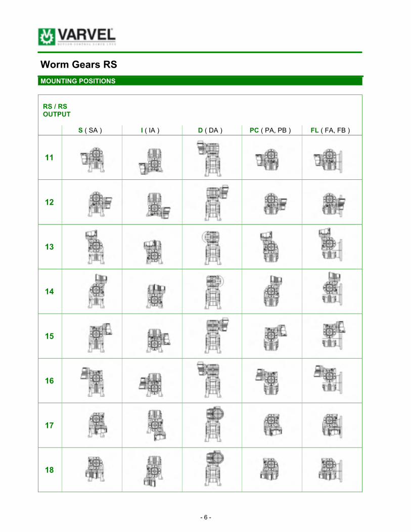
Worm Gears RS
MOUNTING POSITIONS
RS / RS OUTPUT
S ( SA ) I ( IA ) D ( DA ) PC ( PA, PB ) FL ( FA, FB )
11
12
13
14
15
16
17
18

- 7 -
Worm Gears RT
MOUNTING POSITIONS
B3 (std)
B6 B7 B8 RT, RT / RT OUTPUT
V5 V6 F (std) Fi
20 (std)
21 22 23 RT / RT INPUT
24 25 26 27

- 8 -
Worm Gears RT
SERVICE FACTORS – WEIGHTS & LUBRICANTS – INPUT LOADS
F1 a b c F2 d
3 - 4 h 0.8 1.0 1.5 6 1.0
8 - 10 h 1.0 1.2 1.8 60 1.2
SERVICE FACTORS
FS = F1 x F2
10 - 24 h 1.4 1.6 2.0 120 1.4
F1 = Load & time factor F2 = Running factor a = Uniform load b = Variable load c = Shock load d = Start/stops per hour
RT lb pt RT / RT lb pt
28 2.43 0.06 28 / 28 5,51 0.06/0.06
40 5.51 0.17 28 / 40 8,60 0.06/0.17
50 8.38 0.28 28 / 50 11,46 0.06/0.28
60 14.33 0.43 28 / 60 17,42 0.06/0.43
70 19.84 0.75 40 / 70 26,46 0.17/0.75
85 29.76 1.28 40 / 85 36,38 0.17/1.28
110 85.98 3.20 50 / 110 99,21 0.28/3.20
* 130 110.23 5.86 *60 / 130 125,66 0.43/5.86
* 150 176.37 9.37 *70 / 150 198,41 0.75/9.37
WEIGHTS & LUBRICANTS 1 pt (US) = 0.47 litre
(*) - RS sizes only

- 9 -
Worm Gears RS-RT
OUTPUT LOADS
OUTPUT OVERHUNG LOADS (OHL) R2 [lb] WITH STANDARD BEARINGS
A2 = 0.2 x R2
RPM 336 240 168 112 84 60 42 35 30 24 22 17
RT28 - - - 97 108 119 130 134 151 162 173 195 205 216
RT40 216 216 238 260 292 324 346 368 389 411 433 497
RT50 314 270 314 368 411 433 497 519 562 606 627 692
RT60 487 519 541 627 714 779 843 930 995 1081 1146 1211
RT70 562 584 627 779 843 908 973 1125 1189 1276 1363 1449
RT85 714 714 800 952 1016 1168 1189 1363 1427 1536 1622 1795
RT110 - - - 843 898 1125 1168 1276 1233 1622 1687 1730 1903 2119
RS130 - - - 1081 1265 1330 1406 1427 1687 1903 2055 2098 2271 2487
RS150 - - - 1406 1665 1795 1903 1946 2379 2595 2703 2812 3028 3244
Higher radial loads available upon request. Input shaft radial loads available upon request.

- 10 -
Worm Gears RS-RT
RATINGS 3600 RPM 2-POLES, SF=1.0
Ratio 5 7 10 15 20 28 40 49 56 70 80 100 3600 RPM
output RPM
720 514 360 240 180 129 90 73 64 51 45 36
RS – RT HP - - - 1.06 0.82 0.59 0.42 0.39 0.27 0.22 0.20 0.15 0.13 0.07
28 (1.10)
in-lb - - - 115 124 124 115 133 124 115 106 97 89 62
eff. - - - 0.86 0.83 0.79 0.77 0.69 0.64 0.61 0.54 0.49 0.49 0.46
RS – RT HP 3.52 2.51 2.01 1.37 0.94 0.82 0.60 0.50 0.44 0.35 0.32 0.25
40 (1.57)
in-lb 283 274 301 301 266 301 283 274 266 257 248 230
eff. 0.89 0.87 0.85 0.81 0.78 0.72 0.66 0.62 0.6 0.57 0.54 0.51
RS – RT HP 1.49 1.46 1.42 1.36 1.31 1.21 1.11 1.04 1.01 0.96 0.91 0.85
50 (1.97)
in-lb 513 549 522 540 460 584 522 496 469 407 434 354
eff. 0.9 0.88 0.86 0.82 0.8 0.75 0.69 0.66 0.64 0.58 0.58 0.52
RS – RT HP 9.72 7.38 5.87 4.36 3.18 2.68 1.84 1.21 1.22 1.01 0.87 0.57
60 (2.36)
in-lb 797 823 920 974 956 1027 929 752 814 814 752 602
eff. 0.9 0.88 0.87 0.84 0.82 0.76 0.73 0.71 0.66 0.64 0.6 0.58
RS – RT HP 13.58 9.55 7.21 5.36 4.02 3.69 2.51 2.01 1.68 1.34 1.16 0.91
70 (2.76)
in-lb 1115 1080 1151 1230 1204 1425 1372 1257 1151 1062 1018 947
eff. 0.91 0.89 0.88 0.85 0.83 0.78 0.74 0.7 0.68 0.63 0.61 0.58
RS – RT HP 21.79 16.09 12.57 8.88 7.21 5.20 4.02 3.35 2.85 2.18 1.84 1.56
85 (3.35)
in-lb 1788 1814 1991 2071 2097 2080 2213 2142 2027 1859 1770 1682
eff. 0.91 0.89 0.88 0.86 0.8 0.8 0.76 0.72 0.71 0.67 0.64 0.6
RS – RT HP - - - 29.33 24.81 17.94 14.42 11.73 8.38 7.54 6.03 5.20 5.03 3.52
110 (4.33)
in-lb - - - 3319 3938 4160 4337 4691 4602 4823 4337 4646 4779 3983
eff. - - - 0.9 0.88 0.86 0.84 0.79 0.76 0.73 0.71 0.7 0.67 0.62
RS HP - - - 44.09 36.21 26.48 20.45 15.76 12.91 10.06 8.88 6.54 5.53 4.02
130 (5.12)
in-lb - - - 5000 5797 6239 6328 6328 7213 6549 6903 5930 5487 4956
eff. - - - 0.9 0.89 0.87 0.86 0.8 0.78 0.74 0.77 0.72 0.68 0.68
RS HP - - - 62.02 49.62 38.22 28.66 22.80 17.94 14.25 11.06 9.22 8.21 6.03
150 (5.91)
in-lb - - - 7036 7965 8983 8894 9425 10355 9647 8585 8408 8098 7478
eff. - - - 0.9 0.89 0.87 0.86 0.82 0.8 0.77 0.77 0.72 0.68 0.68

- 11 -
Worm Gears RS-RT
1800 RPM 4-POLES, SF=1.0 RATINGS
Ratio 5 7 10 15 20 28 40 49 56 70 80 100 1800 RPM
output RPM
360 257 180 120 90 64 45 37 32 26 23 18
RT HP - - - 0.75 0.55 0.39 0.27 0.27 0.17 0.15 0.13 0.10 0.08 0.05
28 (1.10)
in-lb - - - 159 159 159 142 177 150 150 133 106 106 71
eff. - - - 0.84 0.81 0.77 0.74 0.66 0.62 0.57 0.51 0.45 0.45 0.43
RT HP 1.87 1.84 1.36 0.92 0.64 0.62 0.42 0.35 0.30 0.23 0.20 0.15
40 (1.57)
in-lb 398 398 407 389 345 425 372 363 336 319 283 257
eff. 0.87 0.85 0.83 0.78 0.75 0.68 0.61 0.58 0.56 0.52 0.50 0.46
RT HP 4.53 3.02 2.18 1.56 1.06 1.06 0.69 0.62 0.52 0.42 0.34 0.22
50 (1.97)
in-lb 717 664 664 655 575 752 637 673 628 558 513 381
eff. 0.88 0.86 0.84 0.78 0.76 0.71 0.64 0.62 0.60 0.53 0.52 0.47
RT HP 6.87 4.69 3.86 2.68 2.01 1.68 1.26 1.04 0.91 0.77 0.62 0.42
60 (2.36)
in-lb 1106 1000 1177 1151 1080 1230 1195 1133 1089 1080 938 735
eff. 0.89 0.86 0.84 0.81 0.77 0.71 0.66 0.62 0.60 0.55 0.53 0.49
RT HP 9.55 6.71 5.20 3.69 3.02 2.51 2.01 1.41 1.24 0.97 0.84 0.62
70 (2.76)
in-lb 1558 1469 1593 1664 1717 1912 2106 1673 1593 1443 1363 1151
eff. 0.89 0.88 0.86 0.83 0.81 0.75 0.71 0.67 0.64 0.59 0.56 0.52
RT HP 15.25 10.39 7.71 5.70 4.86 3.69 2.68 2.35 2.01 1.61 1.44 0.92
85 (3.35)
in-lb 2469 2292 2372 2558 2850 2823 2876 2797 2699 2567 2478 1859
eff. 0.90 0.88 0.86 0.83 0.82 0.76 0.72 0.67 0.68 0.63 0.60 0.56
RT HP - - - 20.95 15.09 10.90 9.55 7.38 5.87 4.53 3.69 3.35 2.51 1.84
110 (4.33)
in-lb - - - 4646 4708 4956 5726 5682 6115 5584 5266 5620 4646 4151
eff. - - - 0.88 0.87 0.84 0.83 0.76 0.73 0.71 0.70 0.67 0.66 0.61
RS HP - - - 31.85 25.14 18.44 14.25 12.57 9.22 6.54 6.20 4.53 4.02 3.02
130 (5.12)
in-lb - - - 7142 7877 8496 8629 9735 10089 8408 8894 7655 7169 6638
eff. - - - 0.89 0.87 0.85 0.84 0.77 0.76 0.72 0.71 0.67 0.63 0.61
RS HP - - - 41.74 35.20 26.82 20.95 15.92 13.41 9.89 8.55 6.37 5.53 4.36
150 (5.91)
in-lb - - - 9381 11151 12479 12656 12700 14868 12744 12567 10886 10355 9912
eff. - - - 0.89 0.88 0.86 0.84 0.79 0.77 0.73 0.73 0.68 0.65 0.63

- 12 -
Worm Gears RS-RT
RATINGS 1200 RPM 6-POLES, SF=1.0
Ratio 5 7 10 15 20 28 40 49 56 70 80 100 1200 RPM
output RPM
240 171 120 80 60 43 30 24 21 17 15 12
RS – RT HP - - - 0.60 0.40 0.30 0.22 0.20 0.13 0.12 0.10 0.07 0.05 0.03
28 (1.10)
in-lb - - - 195 177 186 168 195 177 168 142 115 97 71
eff. - - - 0.82 0.78 0.72 0.7 0.61 0.56 0.52 0.45 0.43 0.4 0.37
RS – RT HP 2.01 1.41 1.07 0.74 0.50 0.47 0.32 0.27 0.23 0.20 0.17 0.13
40 (1.57)
in-lb 478 460 478 460 398 460 407 381 363 354 345 319
eff. 0.86 0.83 0.8 0.74 0.7 0.63 0.56 0.52 0.49 0.46 0.44 0.42
RS – RT HP 3.52 2.51 1.84 1.26 0.87 0.85 0.59 0.47 0.42 0.32 0.28 0.20
50 (1.97)
in-lb 850 841 841 805 699 876 752 717 708 593 593 487
eff. 0.86 0.85 0.81 0.76 0.72 0.65 0.58 56 0.54 0.47 0.46 42
RS – RT HP 5.36 4.02 3.18 2.35 1.68 1.46 0.94 0.72 0.67 0.54 0.47 0.32
60 (2.36)
in-lb 1328 1328 1443 1469 1425 1549 1345 1195 1151 1106 1018 832
eff. 0.87 0.85 0.83 0.75 0.76 0.68 0.64 0.61 0.55 0.53 0.48 0.47
RS – RT HP 7.54 5.36 4.02 2.85 2.18 2.01 1.46 1.07 0.89 0.70 0.64 0.50
70 (2.76)
in-lb 1876 1788 1867 1929 1832 2142 2124 1814 1655 1505 1416 1301
eff. 0.88 0.86 0.83 0.79 0.77 0.7 0.654 0.62 0.59 0.54 0.5 0.46
RS – RT HP 12.07 8.38 6.54 5.03 3.52 3.02 2.51 1.68 1.39 1.22 1.07 0.85
85 (3.35)
in-lb 2991 2832 3098 3345 3142 3301 3629 3098 2938 2655 2567 2301
eff. 0.88 0.86 0.84 0.8 0.78 0.71 0.66 0.672 0.671 0.55 0.53 0.48
RS – RT HP - - - 16.43 13.41 9.55 7.38 6.20 4.53 3.86 3.18 2.85 2.51 1.58
110 (4.33)
in-lb - - - 5620 6372 6593 6593 7036 6903 6903 6107 6770 6328 4425
eff. - - - 0.87 0.85 0.82 0.79 0.73 0.68 0.64 0.62 0.59 0.57 0.5
RS HP - - - 24.98 19.61 14.08 10.90 8.55 6.87 5.20 4.69 3.52 3.02 2.18
130 (5.12)
in-lb - - - 8629 9470 9868 9868 10133 10753 9691 10133 8496 7877 7124
eff. - - - 0.88 0.86 0.83 0.81 0.75 0.7 0.67 0.68 0.63 0.58 0.57
RS HP - - - 34.87 26.65 20.45 15.59 12.24 9.39 7.54 5.53 4.86 4.19 3.35
150 (5.91)
in-lb - - - 12036 13010 14470 14381 14691 15399 14160 12125 12302 11417 10886
eff. - - - 0.88 0.87 0.84 0.82 0.77 0.73 0.69 0.69 0.64 0.61 0.58
- 13 -
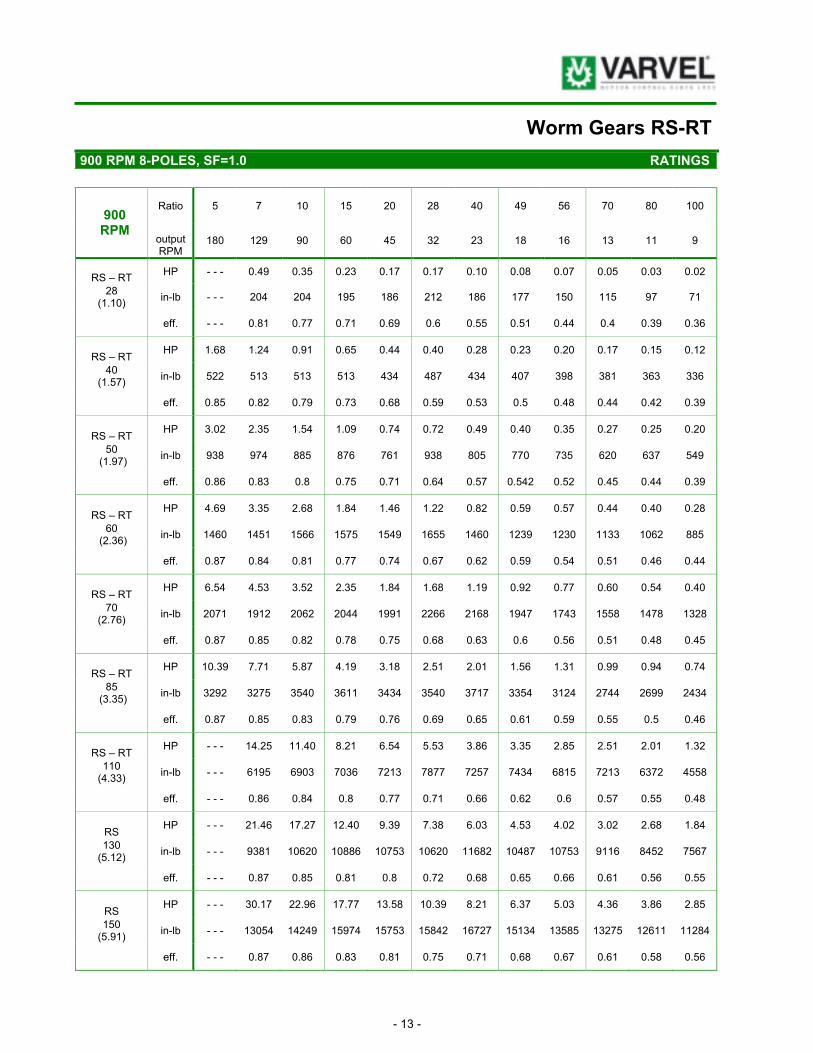
Worm Gears RS-RT
900 RPM 8-POLES, SF=1.0 RATINGS
Ratio 5 7 10 15 20 28 40 49 56 70 80 100 900
RPM output RPM
180 129 90 60 45 32 23 18 16 13 11 9
RS – RT HP - - - 0.49 0.35 0.23 0.17 0.17 0.10 0.08 0.07 0.05 0.03 0.02
28 (1.10)
in-lb - - - 204 204 195 186 212 186 177 150 115 97 71
eff. - - - 0.81 0.77 0.71 0.69 0.6 0.55 0.51 0.44 0.4 0.39 0.36
RS – RT HP 1.68 1.24 0.91 0.65 0.44 0.40 0.28 0.23 0.20 0.17 0.15 0.12
40 (1.57)
in-lb 522 513 513 513 434 487 434 407 398 381 363 336
eff. 0.85 0.82 0.79 0.73 0.68 0.59 0.53 0.5 0.48 0.44 0.42 0.39
RS – RT HP 3.02 2.35 1.54 1.09 0.74 0.72 0.49 0.40 0.35 0.27 0.25 0.20
50 (1.97)
in-lb 938 974 885 876 761 938 805 770 735 620 637 549
eff. 0.86 0.83 0.8 0.75 0.71 0.64 0.57 0.542 0.52 0.45 0.44 0.39
RS – RT HP 4.69 3.35 2.68 1.84 1.46 1.22 0.82 0.59 0.57 0.44 0.40 0.28
60 (2.36)
in-lb 1460 1451 1566 1575 1549 1655 1460 1239 1230 1133 1062 885
eff. 0.87 0.84 0.81 0.77 0.74 0.67 0.62 0.59 0.54 0.51 0.46 0.44
RS – RT HP 6.54 4.53 3.52 2.35 1.84 1.68 1.19 0.92 0.77 0.60 0.54 0.40
70 (2.76)
in-lb 2071 1912 2062 2044 1991 2266 2168 1947 1743 1558 1478 1328
eff. 0.87 0.85 0.82 0.78 0.75 0.68 0.63 0.6 0.56 0.51 0.48 0.45
RS – RT HP 10.39 7.71 5.87 4.19 3.18 2.51 2.01 1.56 1.31 0.99 0.94 0.74
85 (3.35)
in-lb 3292 3275 3540 3611 3434 3540 3717 3354 3124 2744 2699 2434
eff. 0.87 0.85 0.83 0.79 0.76 0.69 0.65 0.61 0.59 0.55 0.5 0.46
RS – RT HP - - - 14.25 11.40 8.21 6.54 5.53 3.86 3.35 2.85 2.51 2.01 1.32
110 (4.33)
in-lb - - - 6195 6903 7036 7213 7877 7257 7434 6815 7213 6372 4558
eff. - - - 0.86 0.84 0.8 0.77 0.71 0.66 0.62 0.6 0.57 0.55 0.48
RS HP - - - 21.46 17.27 12.40 9.39 7.38 6.03 4.53 4.02 3.02 2.68 1.84
130 (5.12)
in-lb - - - 9381 10620 10886 10753 10620 11682 10487 10753 9116 8452 7567
eff. - - - 0.87 0.85 0.81 0.8 0.72 0.68 0.65 0.66 0.61 0.56 0.55
RS HP - - - 30.17 22.96 17.77 13.58 10.39 8.21 6.37 5.03 4.36 3.86 2.85
150 (5.91)
in-lb - - - 13054 14249 15974 15753 15842 16727 15134 13585 13275 12611 11284
eff. - - - 0.87 0.86 0.83 0.81 0.75 0.71 0.68 0.67 0.61 0.58 0.56

- 14 -
Helical Worm Gears RA-TA
RATINGS 1800 RPM, HELICAL 1/3.5, SF=1.0
Ratio 3.5 6.3 8 XA
RPM
514 286 225
HP 0.84 0.39 0.30
in-lb 106 89 80 XA63
R2 [lb] 8435 9732 9732
HP 1.84 0.87 0.62
in-lb 230 195 177 XA71
R2 [lb] 10597 12111 12111
HP 5.20 2.51 1.84
in-lb 602 575 531 XA80
R2 [lb] 13193 15139 15139
HP 14.58 6.71 3.69
in-lb 2080 1443 1204 XA100
R2 [lb] 44979 31198 26030
Helical Single-Stage Attachment XA
A2 = 0.2 x R2
Tot.ratio 18 25 35 53 70 98 140 172 196 245 280 350
Ratio2 5 7 10 15 20 28 40 49 56 70 80 100 Ratio1
3.5:1 RPM 100 72 51 34 26 18 13 10 9 7 6 5
HP 0.94 0.92 0.67 0.47 0.34 0.32 0.22 0.18 0.17 0.10 0.08 0.05
in-lb 0.37 637 637 620 531 620 566 513 496 372 310 221 63/40
eff. 0.80 0.78 0.75 0.7 0.63 0.56 0.5 0.46 0.44 0.41 0.4 0.35
HP 1.37 1.71 1.17 0.84 0.55 0.54 0.35 0.34 0.27 0.18 0.15 0.10
in-lb 1270 1195 1124 1106 929 1106 929 1018 885 708 620 443 63/50 71/50
eff. 0.81 0.79 0.76 0.7 0.66 0.59 0.52 0.5 0.46 0.42 0.4 0.35
HP 2.70 2.56 1.98 1.39 0.96 0.89 0.55 0.45 0.39 0.32 0.25 0.17
in-lb 1940 1814 1920 1903 1699 1920 1566 1505 1345 1283 974 752
63/60 71/60 80/60 eff. 0.82 0.8 0.77 0.72 0.7 0.61 0.57 0.54 0.49 0.45 0.38 0.36
HP 3.57 3.29 2.48 1.81 1.29 1.21 0.84 0.72 0.60 0.50 0.44 0.32
in-lb 2500 2345 2434 2522 2301 2744 2390 2390 2080 1991 1770 1593 71/70 80/70
eff. 0.83 0.81 0.78 0.74 0.71 0.64 0.57 0.54 0.49 0.45 0.41 0.39
HP 5.5 5.26 4.01 2.97 2.30 1.86 1.34 1.09 0.97 0.82 0.67 0.44
in-lb 3900 3806 3983 4204 4160 4204 3938 3717 3629 3452 3009 2213 71/85 80/85
eff. 0.84 0.82 0.79 0.75 0.72 0.64 0.58 0.55 0.53 0.48 0.44 0.4
HP - - - 10.09 7.76 6.00 4.38 3.65 2.68 2.13 1.88 1.44 1.44 0.91
in-lb - - - 7390 7921 8408 8054 8496 8408 7523 7257 6638 6549 4779 80/110
100/110 eff. - - - 0.83 0.81 0.74 0.73 0.66 0.62 0.57 0.55 0.52 0.45 0.42
HP - - - 11.73 11.40 9.22 6.37 5.20 3.86 2.85 2.51 2.18 1.84 1.34
in-lb - - - 8629 11682 13231 11948 12656 12213 11505 11063 10620 9558 7788 100/130
eff. - - - 0.83 0.81 0.77 0.75 0.67 0.63 0.64 0.62 0.6 0.5 0.48
HP - - - 13.24 13.07 12.57 9.55 7.54 5.53 4.53 4.02 3.02 2.68 1.68
in-lb - - - 11415 13585 18497 18231 18851 18143 18054 17921 15045 12912 10620 100/150
eff. - - - 0.84 0.82 0.79 0.76 0.69 0.66 0.64 0.62 0.6 0.52 0.5

- 15 -
Helical Worm Gears RA-TA
1800 RPM, HELICAL 1/6.3, SF=1.0 RATINGS
Total ratio
32 44 63 95 126 176 252 309 353 441 504 630
Ratio2 5 7 10 15 20 28 40 49 56 70 80 100 Ratio1
6.3:1
RPM 56 41 29 19 14 10 7 6 5 4 4 3
HP 0.60 0,59 0,42 0,28 0,20 0,18 0,13 0,10 0,10 0,08 0,07 0,05
in-lb 699 699 690 655 558 611 558 504 487 469 451 407 63/40
eff. 0.78 0,76 0,72 0,67 0,6 0,52 0,45 0,43 0,39 0,35 0,34 0,31
HP 1.09 1,04 0,70 0,50 0,34 0,34 0,23 0,18 0,17 0,15 0,12 0,08
in-lb 1320 1283 1177 1151 1000 1221 1018 956 885 814 788 637 63/50 71/50
eff. 0.80 0,78 0,74 0,67 0,63 0,55 0,48 0,45 0,42 0,36 0,36 0,31
HP 1.63 1,54 1,24 0,87 0,67 0,59 0,39 0,27 0,27 0,18 0,17 0,13
in-lb 1980 1929 2097 2080 2036 2106 1859 1416 1549 1248 1151 1080
63/60 71/60 80/60
eff. 0.81 0,79 0,75 0,7 0,67 0,57 0,53 0,49 0,45 0,42 0,37 0,35
HP 2.08 2,01 1,59 1,14 0,84 0,74 0,54 0,44 0,39 0,30 0,28 0,20
in-lb 2600 2558 2744 2744 2584 2832 2292 2407 2248 1956 1859 1682 71/70 80/70
eff. 0.82 0,8 0,76 0,71 0,68 0,6 0,54 0,5 0,46 0,42 0,37 0,36
HP 3.48 3,35 2,68 1,84 1,41 1,16 0,89 0,72 0,62 0,47 0,44 0,37
in-lb 4400 4337 4655 4567 4381 4434 4425 4124 3974 3460 3363 3053 71/85 80/85
eff. 0.82 0,8 0,77 0,72 0,69 0,6 0,55 0,51 0,5 0,46 0,42 0,36
HP - - - 7,21 5,36 4,02 3,02 2,68 1,84 1,68 1,34 1,11 0,85 0,54
in-lb - - - 9116 9735 10178 9735 10355 9824 9735 8806 8408 6903 4868 80/110
100/110
eff. - - - 0,81 0,79 0,74 0,71 0,63 0,57 0,53 0,52 0,48 0,45 0,39
HP - - - 10,74 8,28 6,24 4,54 3,97 2,77 2,46 2,10 1,71 1,37 0,79
in-lb - - - 14160 15045 15930 15045 15930 15045 15045 14160 14160 11505 7965 100/130
eff. - - - 0,83 0,8 0,75 0,73 0,63 0,6 0,55 0,53 0,52 0,46 0,45
HP - - - 14,10 11,08 8,45 6,32 5,06 3,87 3,05 2,36 2,08 1,83 1,41
in-lb - - - 18585 20355 22125 21240 21240 22125 20355 17700 15930 15930 15045 100/150
eff. - - - 0,83 0,81 0,77 0,74 0,66 0,63 0,6 0,59 0,81 0,48 0,47

- 16 -
Helical Worm Gears RA-TA
RATINGS 1800 RPM, HELICAL 1/8, SF=1.0
Total ratio
40 56 80 120 160 224 320 392 448 560 640 800
Ratio2 5 7 10 15 20 28 40 49 56 70 80 100 Ratio1
8:1
RPM 45 32 23 15 11 8.0 6.6 4.6 4.0 3.2 2.8 2,2
HP 0.55 0.54 0.39 0.27 0.18 0.18 0.13 0.10 0.08 0.05 0.05 0.03
in-lb 823 823 788 743 637 752 664 611 522 398 336 239 63/40
eff. 0.71 0.75 0.72 0.65 0.59 0.5 0.44 0.41 0.38 0.36 0.34 0.31
HP 1.05 0.97 0.69 0.47 0.34 0.30 0.22 0.17 0.15 0.10 0.08 0.05
in-lb 1620 1505 1460 1363 1151 1328 1151 1062 1018 761 646 469 63/50 71/50
eff. 0.79 0.77 0.73 0.67 0.61 0.55 0.47 0.45 0.41 0.36 0.37 0.31
HP 1.6 1.46 1.14 0.82 0.57 0.52 0.35 0.27 0.25 0.17 0.13 0.08
in-lb 2480 2301 2478 2434 2124 2390 2080 1947 1770 1372 1106 814
63/60 71/60 80/60
eff. 0.80 0.78 0.75 0.69 0.65 0.57 0.51 0.5 0.43 0.41 0.37 0.35
HP 1.36 1.26 0.88 0.63 0.44 0.48 0.28 0.24 0.20 0.16 0.12 0.05
in-lb 3560 3363 3230 3186 2876 3894 2832 2832 2434 2168 1770 1283 71/70 80/70
eff. 0.81 0.79 0.76 0.7 0.67 0.6 0.53 0.5 0.45 0.41 0.38 0.35
HP 3.2 2.95 2.38 1.79 1.42 1.09 0.80 0.67 0.55 0.44 0.34 0.22
in-lb 5050 4691 5266 5487 5487 5310 4956 4868 4514 3983 3186 2301 71/85 80/85
eff. 0.81 0.79 0.77 0.71 0.67 0.6 0.54 0.52 0.5 0.45 0.41 0.37
HP - - - 5.73 4.61 3.30 2.55 2.16 1.63 1.22 1.07 0.87 0.72 0.45
in-lb - - - 9248 10355 10443 10266 10620 10443 9027 8673 8142 7523 4868 80/110
100/110
eff. - - - 0.8 0.78 0.73 0.7 0.61 0.56 0.52 0.5 0.46 0.45 0.38
HP - - - 5.53 5.03 5.36 3.86 3.02 2.01 1.84 1.51 1.17 1.17 0.84
in-lb - - - 8850 10974 16284 15620 15576 15045 14691 14160 12700 11771 10266 100/130
eff. - - - 0.8 0.78 0.73 0.72 0.62 0.58 0.56 0.54 0.51 0.45 0.43
HP - - - 6.20 5.70 6.03 5.70 4.53 3.35 2.85 2.35 1.84 1.68 1.34
in-lb - - - 10001 12611 19028 22833 23674 25311 22568 22037 18674 17435 16417 100/150
eff. - - - 0.81 0.79 0.75 0.72 0.63 0.61 0.56 0.57 0.49 0.46 0.45

- 17 -
Double Worm Gears RS-RT
1800 RPM, SF=1.0 RATINGS
Ratio1 10 15 20 28 40 56 56 70 100 100 100 100
Ratio2 28 28 28 28 28 28 40 40 40 56 80 100
Total R 280 420 560 784 1120 1568 2240 2800 4000 5600 8000 10000
RPM 6.4 4,3 3,2 2,3 1,6 1,2 0,80 0,64 0,45 0,32 0,23 0,18
HP 0.055 0.05 0.04 0.04 0.03 0.02 0.02 0.01 0.01 0.005 0.003 0.002
in-lb 300 310 319 319 319 310 266 266 266 142 106 97 RT - RT 28 / 28
eff. 0.40 0.38 0.37 0.32 0.3 0.25 0.21 0.20 0.18 0.14 0.12 0.13
HP 0.14 0.13 0.10 0.08 0.06 0.05 0.04 0.04 0.02 0.02 0.008 0.005
in-lb 740 752 752 708 708 708 646 673 620 549 363 221 RT - RT 28 / 40
eff. 0.42 0.39 0.37 0.33 0.31 0.25 0.21 0.18 0.18 0.15 0.14 0.12
HP 0.24 0.22 0.18 0.15 0.12 0.10 0.06 0.06 0.05 0.03 0.02 0.01
in-lb 1300 1328 1328 1416 1549 1416 1106 1159 1301 1106 690 434 RT - RT 28 / 50
eff. 0.42 0.39 0.37 0.33 0.31 0.25 0.22 0.19 0.19 0.16 0.14 0.12
HP 0.36 0.33 0.26 0.22 0.15 0.15 0.11 0.09 0.05 0.05 0.03 0.02
in-lb 2050 2124 2124 2168 2036 2301 2168 1920 1451 1726 1133 805 RT - RT 28 / 60
eff. 0.45 0.42 0.4 0.35 0.33 0.27 0.23 0.21 0.2 0.16 0.14 0.13
HP 0.55 0.50 0.42 0.33 0.26 0.20 0.14 0.12 0.10 0.07 0.04 0.03
in-lb 3100 3363 3540 3540 3496 3363 3275 3053 3186 2841 1779 1363 RT - RT 40 / 70
eff. 0.46 0.44 0.42 0.38 0.33 0.3 0.27 0.25 0.22 0.2 0.15 0.14
HP 0.8 0.75 0.62 0.46 0.38 0.30 0.23 0.20 0.15 0.12 0.07 0.04
in-lb 5100 5266 5531 5177 5531 5399 5443 5266 5000 4868 3301 2336 RT - RT 40 / 85
eff. 0.49 0.46 0.44 0.4 0.35 0.32 0.28 0.26 0.23 0.2 0.17 0.15
HP 1.6 1.45 1.27 0.97 0.76 0.64 0.49 0.39 0.27 0.21 0.14 0.09
in-lb 10200 10532 11505 11505 11328 11948 11859 10709 9470 8673 7169 4956 RT - RT 50 /110
eff. 0.50 0.48 0.45 0.42 0.37 0.33 0.3 0.27 0.24 0.2 0.18 0.16
HP 2.7 2.51 1.84 1.26 0.92 0.92 0.62 0.42 0.42 0.42 0.42 0.42
in-lb 17100 17833 17081 14780 13541 17833 16196 12479 15665 16373 12567 10841 RS
60 / 130
eff. 0.53 0.5 0.46 0.43 0.4 0.35 0.33 0.3 0.27 0.25 0.21 0.2
kW 3.3 3.02 2.51 1.84 1.26 1.26 0.92 0.62 0.62 0.42 0.42 0.42
in-lb 27400 22745 25046 22745 21771 25223 26727 20576 25444 23630 18895 17656 RS
70 / 150
eff. 0.55 0.52 0.5 0.46 0.43 0.39 0.36 0.33 0.31 0.27 0.23 0.22

- 18 -
Worm Gears RS
DIMENSIONS
I D
FL PC RS
S
- 19 -
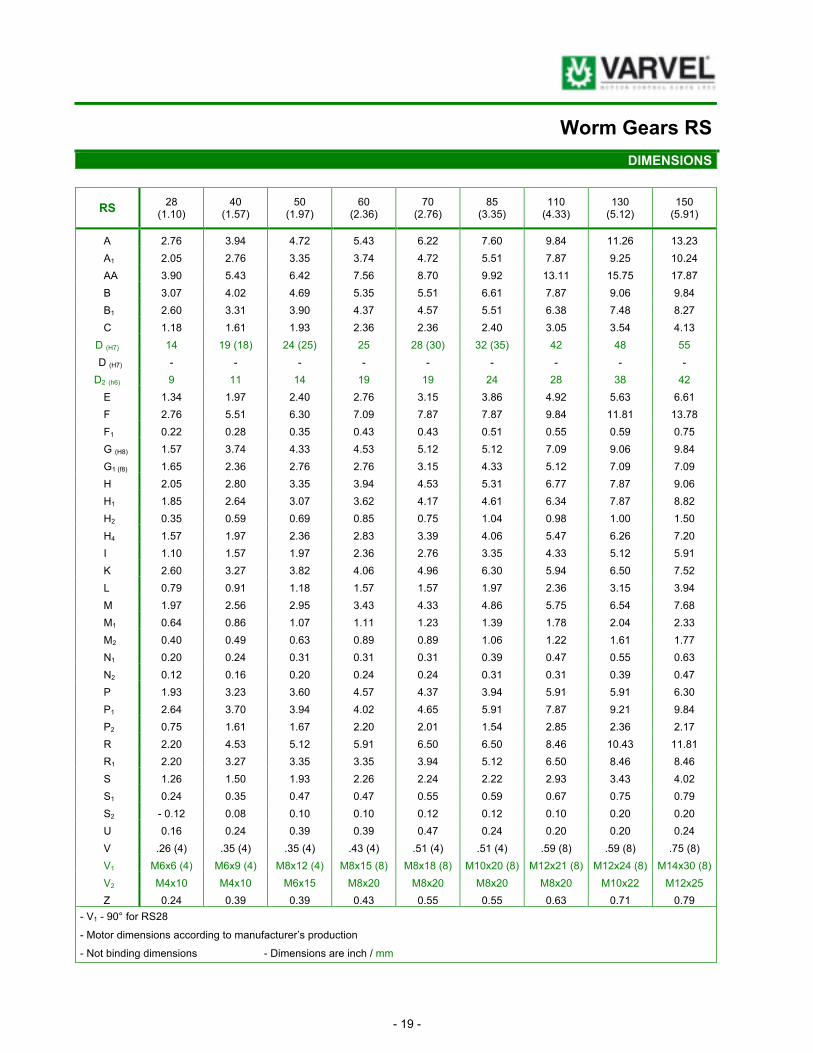
Worm Gears RS
DIMENSIONS
RS 28
(1.10) 40
(1.57) 50
(1.97) 60
(2.36) 70
(2.76) 85
(3.35) 110
(4.33) 130
(5.12) 150
(5.91)
A 2.76 3.94 4.72 5.43 6.22 7.60 9.84 11.26 13.23
A1 2.05 2.76 3.35 3.74 4.72 5.51 7.87 9.25 10.24
AA 3.90 5.43 6.42 7.56 8.70 9.92 13.11 15.75 17.87
B 3.07 4.02 4.69 5.35 5.51 6.61 7.87 9.06 9.84
B1 2.60 3.31 3.90 4.37 4.57 5.51 6.38 7.48 8.27
C 1.18 1.61 1.93 2.36 2.36 2.40 3.05 3.54 4.13
D (H7) 14 19 (18) 24 (25) 25 28 (30) 32 (35) 42 48 55
D (H7) - - - - - - - - -
D2 (h6) 9 11 14 19 19 24 28 38 42
E 1.34 1.97 2.40 2.76 3.15 3.86 4.92 5.63 6.61
F 2.76 5.51 6.30 7.09 7.87 7.87 9.84 11.81 13.78
F1 0.22 0.28 0.35 0.43 0.43 0.51 0.55 0.59 0.75
G (H8) 1.57 3.74 4.33 4.53 5.12 5.12 7.09 9.06 9.84
G1 (f8) 1.65 2.36 2.76 2.76 3.15 4.33 5.12 7.09 7.09
H 2.05 2.80 3.35 3.94 4.53 5.31 6.77 7.87 9.06
H1 1.85 2.64 3.07 3.62 4.17 4.61 6.34 7.87 8.82
H2 0.35 0.59 0.69 0.85 0.75 1.04 0.98 1.00 1.50
H4 1.57 1.97 2.36 2.83 3.39 4.06 5.47 6.26 7.20
I 1.10 1.57 1.97 2.36 2.76 3.35 4.33 5.12 5.91
K 2.60 3.27 3.82 4.06 4.96 6.30 5.94 6.50 7.52
L 0.79 0.91 1.18 1.57 1.57 1.97 2.36 3.15 3.94
M 1.97 2.56 2.95 3.43 4.33 4.86 5.75 6.54 7.68
M1 0.64 0.86 1.07 1.11 1.23 1.39 1.78 2.04 2.33
M2 0.40 0.49 0.63 0.89 0.89 1.06 1.22 1.61 1.77
N1 0.20 0.24 0.31 0.31 0.31 0.39 0.47 0.55 0.63
N2 0.12 0.16 0.20 0.24 0.24 0.31 0.31 0.39 0.47
P 1.93 3.23 3.60 4.57 4.37 3.94 5.91 5.91 6.30
P1 2.64 3.70 3.94 4.02 4.65 5.91 7.87 9.21 9.84
P2 0.75 1.61 1.67 2.20 2.01 1.54 2.85 2.36 2.17
R 2.20 4.53 5.12 5.91 6.50 6.50 8.46 10.43 11.81
R1 2.20 3.27 3.35 3.35 3.94 5.12 6.50 8.46 8.46
S 1.26 1.50 1.93 2.26 2.24 2.22 2.93 3.43 4.02
S1 0.24 0.35 0.47 0.47 0.55 0.59 0.67 0.75 0.79
S2 - 0.12 0.08 0.10 0.10 0.12 0.12 0.10 0.20 0.20
U 0.16 0.24 0.39 0.39 0.47 0.24 0.20 0.20 0.24
V .26 (4) .35 (4) .35 (4) .43 (4) .51 (4) .51 (4) .59 (8) .59 (8) .75 (8)
V1 M6x6 (4) M6x9 (4) M8x12 (4) M8x15 (8) M8x18 (8) M10x20 (8) M12x21 (8) M12x24 (8) M14x30 (8)
V2 M4x10 M4x10 M6x15 M8x20 M8x20 M8x20 M8x20 M10x22 M12x25
Z 0.24 0.39 0.39 0.43 0.55 0.55 0.63 0.71 0.79
- V1 - 90° for RS28
- Motor dimensions according to manufacturer’s production
- Not binding dimensions - Dimensions are inch / mm

- 20 -
Helical Worm Gears RA
DIMENSIONS
I D
FL PC RA
S

- 21 -
Helical Worm Gears RA
DIMENSIONS
63 /
63/
63/
71 /
71/
71/
71/
80 /
80/
80/
80/
100 /
100/
100/
RA 40 (1.57)
50 (1.97)
60 (2.36)
50 (1.97)
60 (2.36)
70 (2.76)
85 (3.35)
60 (2.36)
70 (2.76)
85 (3.35)
110 (4.33)
110 (4.33)
130 (5.12)
150 (5.91)
A 3.94 4.72 5.43 4.72 5.43 6.22 7.60 5.43 6.22 7.60 9.84 9.84 11.26 13.23
A1 2.76 3.35 3.74 3.35 3.74 4.72 5.51 3.74 4.72 5.51 7.87 7.87 9.25 10.24
AA 5.43 6.42 7.56 6.42 7.56 8.70 9.92 7.56 8.70 9.92 13.11 13.11 15.75 17.87
B 4.02 4.69 5.35 4.69 5.35 5.51 6.61 5.35 5.51 6.61 7.87 7.87 9.06 9.84
B1 3.31 3.90 4.37 3.90 4.37 4.57 5.51 4.37 4.57 5.51 6.38 6.38 7.48 8.27
C 1.61 1.93 2.36 1.93 2.36 2.36 2.40 2.36 2.36 2.40 3.05 3.05 3.54 4.13
D(H7) 19(18) 24(25) 25 24(25) 25 28(30) 32(35) 25 28(30) 32(35) 42 42 48 55
D(H7) - - - - - - - - - - - - - -
D2 (h6) 11 11 11 14 14 14 14 19 19 19 19 24 24 24
E 1.97 2.40 2.76 2.40 2.76 3.15 3.86 2.76 3.15 3.86 4.92 4.92 5.63 6.61
F 5.51 6.30 7.09 6.30 7.09 7.87 7.87 7.09 7.87 7.87 9.84 9.84 11.81 13.78
F1 0.28 0.35 0.43 0.35 0.43 0.43 0.51 0.43 0.43 0.51 0.55 0.55 0.59 0.75
G (H8) 3.74 4.33 4.53 4.33 4.53 5.12 5.12 4.53 5.12 5.12 7.09 7.09 9.06 9.84
G1 (f8) 2.36 2.76 2.76 2.76 2.76 3.15 4.33 2.76 3.15 4.33 5.12 5.12 7.09 7.09
H 2.80 3.35 3.94 3.35 3.94 4.53 5.31 3.94 4.53 5.31 6.77 6.77 7.87 9.06
H1 2.64 3.07 3.62 3.07 3.62 4.17 4.61 3.62 4.17 4.61 6.34 6.34 7.87 8.82
H2 0.59 0.69 0.85 0.69 0.85 0.75 1.04 0.85 0.75 1.04 0.98 0.98 1.00 1.50
H4 1.97 2.36 2.83 2.36 2.83 3.39 4.06 2.83 3.39 4.06 5.47 5.47 6.26 7.44
I 1.57 1.97 2.36 1.97 2.36 2.76 3.35 2.36 2.76 3.35 4.33 4.33 5.12 5.91
I2 1.26 1.26 1.26 1.57 1.57 1.57 1.57 1.97 1.97 1.97 1.97 2.48 2.48 2.48
K1 6.04 6.73 6.97 6.81 7.20 8.23 8.82 8.15 9.15 9.86 10.41 12.91 13.46 14.49
L 0.91 0.91 0.91 1.18 1.18 1.18 1.18 1.57 1.57 1.57 1.57 1.97 1.97 1.97
M1 0.86 1.07 1.11 1.07 1.11 1.23 1.39 1.11 1.23 1.39 1.78 1.78 2.04 2.33
M2 0.49 0.49 0.49 0.63 0.63 0.63 0.63 0.89 0.89 0.89 0.89 1.06 1.06 1.06
N1 0.24 0.31 0.31 0.31 0.31 0.31 0.39 0.31 0.31 0.39 0.47 0.47 0.55 0.63
N2 0.16 0.16 0.16 0.20 0.20 0.20 0.20 0.24 0.24 0.24 0.24 0.31 0.31 0.31
P 3.23 3.60 4.57 3.60 4.57 4.37 3.94 4.57 4.37 3.94 5.91 5.91 5.91 6.30
P1 3.70 3.94 4.02 3.94 4.02 4.65 5.91 4.02 4.65 5.91 7.87 7.87 9.21 9.84
P2 1.61 1.67 2.20 1.67 2.20 2.01 1.54 2.20 2.01 1.54 2.85 2.85 2.36 2.17
R 4.53 5.12 5.91 5.12 5.91 6.50 6.50 5.91 6.50 6.50 8.46 8.46 10.43 11.81
R1 3.27 3.35 3.35 3.35 3.35 3.94 5.12 3.35 3.94 5.12 6.50 6.50 8.46 8.46
S 1.50 1.93 2.26 1.93 2.26 2.24 2.22 2.26 2.24 2.22 2.93 2.93 3.43 4.02
S1 0.35 0.47 0.47 0.47 0.47 0.55 0.59 0.47 0.55 0.59 0.67 0.67 0.75 0.79
S2 0.08 0.10 0.10 0.10 0.10 0.12 0.12 0.10 0.12 0.12 0.10 0.10 0.20 0.20
U 0.24 0.39 0.39 0.39 0.39 0.47 0.24 0.39 0.47 0.24 0.20 0.20 0.20 0.24
V 0.35 (4) 0.35 (4) 0.43 (4) 0.35 (4) 0.43 (4) 0.51 (4) 0.51 (4) 0.43 (4) 0.51 (4) 0.51 (4) 0.59 (8) 0.59 (8) 0.59 (8) 0.75 (8)
V1 M6x9
(4) M8x12
(4) M8x15
(8) M8x12
(4) M8x15
(8) M8x18
(8) M10x20
(8) M8x15
(8) M8x18
(8) M10x20
(8) M12x21
(8) M12x21
(8) M12x24
(8) M14x30
(8)
V2 M4x10 M4x10 M4x10 M6x15 M6x15 M6x15 M6x15 M8x20 M8x20 M8x20 M8x20 M8x20 M8x20 M8x20
Y1 4.13 4.13 4.13 4.72 4.72 4.72 4.72 5.51 5.51 5.51 5.51 5.51 7.87 7.87
Z 0.39 0.39 0.43 0.39 0.43 0.55 0.55 0.43 0.55 0.55 0.63 0.63 0.71 0.79
- V1 - 90° for RS28
- Motor dimensions according to manufacturer’s production
- Not binding dimensions
- Dimensions are inch / mm

- 22 -
Double Worm Gears RS
DIMENSIONS
S
I D
FL PC RS/RS

- 23 -
Double Worm Gears RS
DIMENSIONS
28 / 40 / 50 / 60 / 70 / RS
28 40 50 60 70 85 110 130 150
A 2.76 3.94 4.72 5.43 6.22 7.60 9.84 11.26 13.23
A1 2.05 2.76 3.35 3.74 4.72 5.51 7.87 9.25 10.24
AA 3.90 5.43 6.42 7.56 8.70 9.92 13.11 15.75 17.87
B 3.07 4.02 4.69 5.35 5.51 6.61 7.87 9.06 9.84
B1 2.60 3.31 3.90 4.37 4.57 5.51 6.38 7.48 8.27
C 1.18 1.61 1.93 2.36 2.36 2.40 3.05 3.54 4.13
D (H7) 14 19 (18) 24 (25) 25 28 (30) 32 (35) 24 (25) 25 28 (30)
D (H7) - - - - - - - - -
D2 (h6) 9 9 9 9 11 11 14 19 19
E 1.34 1.97 2.40 2.76 3.15 3.86 4.92 5.63 6.61
F 2.76 5.51 6.30 7.09 7.87 7.87 9.84 11.81 13.78
F1 0.22 0.28 0.35 0.43 0.43 0.51 0.55 0.59 0.75
G (H8) 1.57 3.74 4.33 4.53 5.12 5.12 7.09 9.06 9.84
G1 (f8) 1.65 2.36 2.76 2.76 3.15 4.33 5.12 7.09 7.09
H 2.05 2.80 3.35 3.94 4.53 5.31 6.77 7.87 9.06
H1 1.85 2.64 3.07 3.62 4.17 4.61 6.34 7.87 8.82
H2 0.35 0.59 0.69 0.85 0.75 1.04 0.98 1.00 1.50
H3 1.57 1.57 1.57 1.57 1.97 1.97 2.36 2.83 3.39
H4 1.57 1.97 2.36 2.83 3.39 4.06 5.47 6.26 7.44
H5 1.34 1.34 1.34 1.34 1.97 1.97 2.40 2.76 3.15
H6 1.85 1.85 1.85 1.85 2.64 2.64 3.07 3.62 4.17
I 1.10 1.57 1.97 2.36 2.76 3.35 4.33 5.12 5.91
I2 1.10 1.10 1.10 1.10 1.57 1.57 1.97 2.36 2.76
K 3.92 4.57 5.45 5.75 7.17 7.83 9.69 9.69 11.81
K1 2.26 2.26 2.26 2.26 2.78 2.78 3.27 3.66 4.61
L 0.79 0.79 0.79 0.79 0.91 0.91 1.18 1.57 1.57
M 1.97 1.97 1.97 1.97 2.56 2.56 2.95 3.43 4.33
M1 0.64 0.86 1.07 1.11 1.23 1.39 1.78 2.04 2.33
M2 0.40 0.40 0.40 0.40 0.49 0.49 0.63 0.89 0.89
N1 0.20 0.24 0.31 0.31 0.31 0.39 0.47 0.55 0.63
N2 0.12 0.12 0.12 0.12 0.16 0.16 0.20 0.24 0.24
P 1.93 3.23 3.60 4.57 4.37 3.94 5.91 5.91 6.30
P1 2.64 3.70 3.94 4.02 4.65 5.91 7.87 9.21 9.84
P2 0.75 1.61 1.67 2.20 2.01 1.54 2.85 2.36 2.17
R 2.20 4.53 5.12 5.91 6.50 6.50 8.46 10.43 11.81
R1 2.20 3.27 3.35 3.35 3.94 5.12 6.50 8.46 8.46
S 1.26 1.50 1.93 2.26 2.24 2.22 2.93 3.43 4.02
S1 0.24 0.35 0.47 0.47 0.55 0.59 0.67 0.75 0.79
S2 -0.12 0.08 0.10 0.10 0.12 0.12 0.10 0.20 0.20
S3 1.18 1.18 1.18 1.18 1.61 1.61 1.93 2.36 2.36
U 0.16 0.24 0.39 0.39 0.47 0.24 0.20 0.20 0.24
V 0.24 (4) 0.35 (4) 0.35 (4) 0.43 (4) 0.51 (4) 0.51 (4) 0.59 (8) 0.59 (8) 0.75 (8)
V1 M6x6 (4) M6x9 (4) M8x12 (4) M8x15 (8) M8x18 (8) M10x20 (8) M12x21 (8) M12x24 (8) M14x30 (8)
V2 M4x10 M4x10 M4x10 M4x10 M4x10 M4x10 M6x15 M8x20 M8x20
Y1 3.15 3.15 3.15 3.54 4.53 4.53 4.33 7.09 7.87
Z 0.24 0.39 0.39 0.43 0.55 0.55 0.63 0.71 0.79
- V1 - 90° for RS28 - Motor dimensions according to manufacturer’s production
- Not binding dimensions - Dimensions are inch / mm

- 24 -
Worm Gears RS
DIMENSIONS ALTERNATIVE MOUNTINGS
SA IA DA
FA - FB - FR
PA - PB
- 25 -
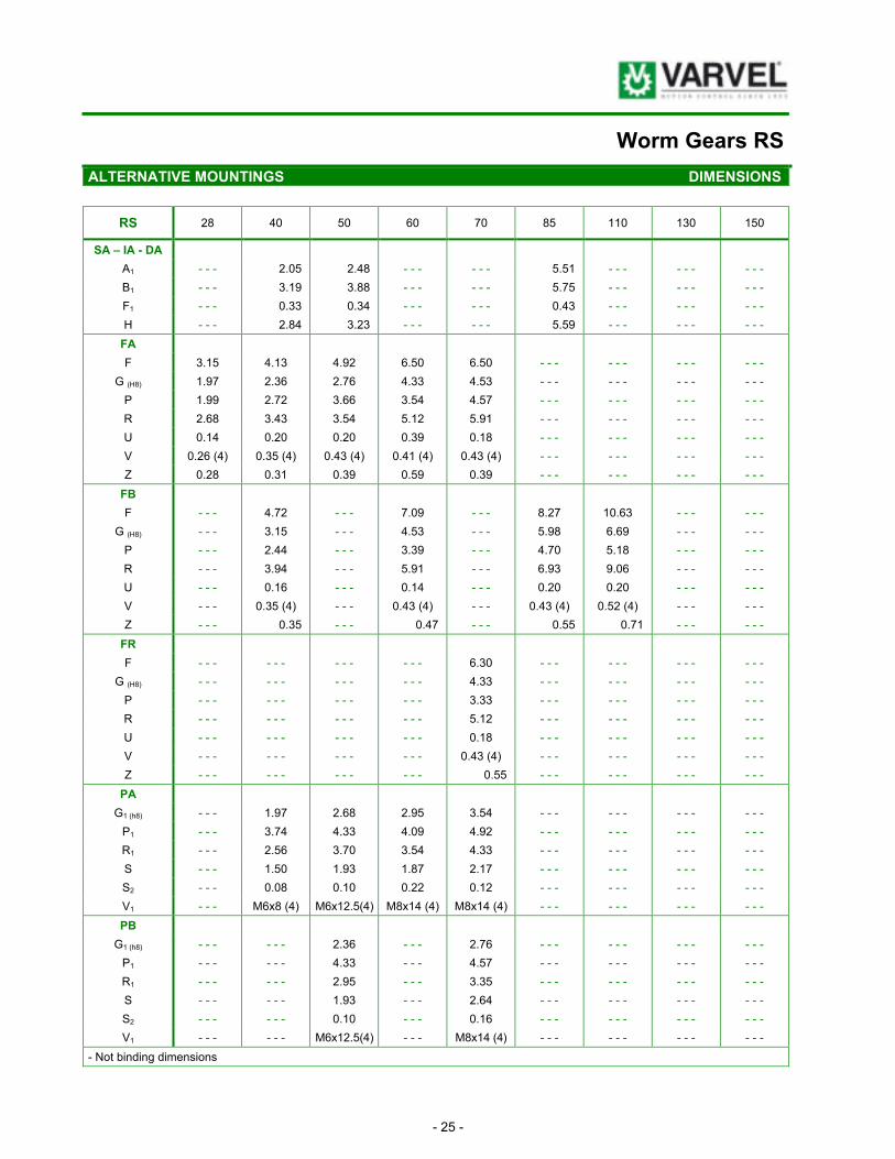
Worm Gears RS
ALTERNATIVE MOUNTINGS DIMENSIONS
RS 28 40 50 60 70 85 110 130 150
SA – IA - DA
A1 - - - 2.05 2.48 - - - - - - 5.51 - - - - - - - - -
B1 - - - 3.19 3.88 - - - - - - 5.75 - - - - - - - - -
F1 - - - 0.33 0.34 - - - - - - 0.43 - - - - - - - - -
H - - - 2.84 3.23 - - - - - - 5.59 - - - - - - - - -
FA
F 3.15 4.13 4.92 6.50 6.50 - - - - - - - - - - - -
G (H8) 1.97 2.36 2.76 4.33 4.53 - - - - - - - - - - - -
P 1.99 2.72 3.66 3.54 4.57 - - - - - - - - - - - -
R 2.68 3.43 3.54 5.12 5.91 - - - - - - - - - - - -
U 0.14 0.20 0.20 0.39 0.18 - - - - - - - - - - - -
V 0.26 (4) 0.35 (4) 0.43 (4) 0.41 (4) 0.43 (4) - - - - - - - - - - - -
Z 0.28 0.31 0.39 0.59 0.39 - - - - - - - - - - - -
FB
F - - - 4.72 - - - 7.09 - - - 8.27 10.63 - - - - - -
G (H8) - - - 3.15 - - - 4.53 - - - 5.98 6.69 - - - - - -
P - - - 2.44 - - - 3.39 - - - 4.70 5.18 - - - - - -
R - - - 3.94 - - - 5.91 - - - 6.93 9.06 - - - - - -
U - - - 0.16 - - - 0.14 - - - 0.20 0.20 - - - - - -
V - - - 0.35 (4) - - - 0.43 (4) - - - 0.43 (4) 0.52 (4) - - - - - -
Z - - - 0.35 - - - 0.47 - - - 0.55 0.71 - - - - - -
FR
F - - - - - - - - - - - - 6.30 - - - - - - - - - - - -
G (H8) - - - - - - - - - - - - 4.33 - - - - - - - - - - - -
P - - - - - - - - - - - - 3.33 - - - - - - - - - - - -
R - - - - - - - - - - - - 5.12 - - - - - - - - - - - -
U - - - - - - - - - - - - 0.18 - - - - - - - - - - - -
V - - - - - - - - - - - - 0.43 (4) - - - - - - - - - - - -
Z - - - - - - - - - - - - 0.55 - - - - - - - - - - - -
PA
G1 (h8) - - - 1.97 2.68 2.95 3.54 - - - - - - - - - - - -
P1 - - - 3.74 4.33 4.09 4.92 - - - - - - - - - - - -
R1 - - - 2.56 3.70 3.54 4.33 - - - - - - - - - - - -
S - - - 1.50 1.93 1.87 2.17 - - - - - - - - - - - -
S2 - - - 0.08 0.10 0.22 0.12 - - - - - - - - - - - -
V1 - - - M6x8 (4) M6x12.5(4) M8x14 (4) M8x14 (4) - - - - - - - - - - - -
PB
G1 (h8) - - - - - - 2.36 - - - 2.76 - - - - - - - - - - - -
P1 - - - - - - 4.33 - - - 4.57 - - - - - - - - - - - -
R1 - - - - - - 2.95 - - - 3.35 - - - - - - - - - - - -
S - - - - - - 1.93 - - - 2.64 - - - - - - - - - - - -
S2 - - - - - - 0.10 - - - 0.16 - - - - - - - - - - - -
V1 - - - - - - M6x12.5(4) - - - M8x14 (4) - - - - - - - - - - - -
- Not binding dimensions

- 26 -
Worm Gears RS
DIMENSIONS ACCESSORIES
AS Solid single output shaft
AD Solid double output shaft
BR Torque arm
TL Torque Limiter
ASC
Safety cap for AS
SL Speed Limiter
BR (plain)
BRV (Vulkollan)
VB NDE wormshaft extension
TLI LUBRICATION
Li Size pt litres 28 0.09 0.04 40 0.21 0.10 50 0.28 0.13 60 0.64 0.30 70 0.96 0.45 85 1.60 0.75 110 4.80 2.25
TLE (external) TLI (internal)

- 27 -
Worm Gears RS
ACCESSORIES DIMENSIONS
RS 28 40 50 60 70 85 110 130 150
AS & A2 2.28 3.15 3.74 4.61 4.61 4.69 6.02 6.97 8.15
AD B2 0.04 0.39 0.39 0.39 0.39 0.39 0.39 0.79 0.79
C 1.18 1.61 1.93 2.36 2.36 2.40 3.05 3.54 4.13
C2 1.18 1.57 1.77 1.97 2.36 2.76 3.94 4.33 4.33
D5 (g 6) 14 19 24 (25) 25 28 32 (35) 42 48 55
E 0.55 0.87 1.10 1.18 1.34 1.50 1.97 2.28 2.48
L6 1.22 1.97 2.17 2.36 2.76 3.15 4.33 5.12 5.12
M5 0.63 0.85 1.06 1.10 1.22 1.38 1.77 2.03 2.32
N5 0.20 0.24 0.31 0.31 0.31 0.39 0.47 0.55 0.63
V5 M5x10 M8x20 M8x20 M8x20 M8x20 M10x25 M10x25 - - - - - -
ASC E3 1.65 2.17 2.44 2.44 2.83 3.54 4.72 - - - - - -
L7 1.42 1.91 2.19 2.70 2.64 3.03 3.35 - - - - - -
S 1.08 1.52 1.83 2.24 2.24 2.64 2.91 - - - - - -
BR & A4 5.26 6.50 7.28 9.06 9.45 12.32 15.28 18.31 20.67
BRV C4 1.32 1.97 2.36 1.97 2.36 2.95 3.94 4.72 4.92
F4 0.41 0.41 0.41 0.41 0.41 0.81 0.81 1.02 1.02
F5 0.39 0.39 0.39 0.39 0.39 0.79 0.79 0.98 0.98
F6 0.28 0.28 0.35 0.35 0.35 0.43 0.51 0.51 0.59
G4 1.65 2.36 2.76 2.76 3.15 4.33 5.12 7.09 7.09
I4 3.15 3.54 3.94 5.91 5.91 7.87 9.84 11.81 13.78
R4 2.20 3.27 3.35 3.35 3.94 5.12 6.50 8.46 8.46
S4 0.16 0.16 0.16 0.24 0.24 0.24 0.24 0.24 0.24
S5 0.59 0.59 0.59 0.79 0.79 0.98 0.98 1.18 1.18
SL L5 3.82 4.49 5.08 5.39 5.24 5.24 5.94 - - - - - -
P1 2.64 3.94 4.33 4.02 4.72 5.91 7.87 - - - - - -
S 1.26 1.50 1.93 2.26 2.24 2.22 2.93 - - - - - -
TLE D6 2.05 2.76 2.76 2.76 3.15 3.94 3.94 - - - - - -
E1 0.39 0.47 0.47 0.59 0.55 0.75 0.94 - - - - - -
E2 1.10 1.46 1.22 1.57 1.81 2.24 2.80 - - - - - -
L3 1.18 1.57 1.97 1.97 2.36 2.76 3.15 - - - - - -
L4 3.70 4.57 4.65 5.04 5.75 6.61 7.91 - - - - - -
M6 2.76 3.66 4.37 4.92 5.28 5.91 7.13 - - - - - -
TLI D 14 18 24 25 28 32 42 - - - - - -
D2 1.57 2.20 2.80 2.80 3.15 3.54 4.92 - - - - - -
D3 0.56 x 0.79 0.77 x 0.81 0.97 x 1.10 1.00 x 1.02 1.12 x 0.87 1.28 x 1.06 1.67 x 1.52 - - - - - -
L 1.77 2.42 3.03 3.41 3.50 3.70 4.29 - - - - - -
M1 0.61* 0.86 1.07 1.07* 1.23 1.39 1.78 - - - - - -
N1
(H9) 0.20 0.24 0.31 0.31 0.31 0.39 0.47 - - - - - -
VB D9 9 11 14 19 19 24 28 38 42
L8 0.79 0.91 1.18 1.57 1.57 1.97 2.36 3.15 3.94
M8 1.69 2.17 2.56 3.03 3.31 4.19 5.71 6.54 7.68
M9 0.40 0.49 0.63 0.89 0.89 1.06 1.22 1.61 1.77
N9 0.12 0.16 0.20 0.24 0.24 0.31 0.31 1.50 1.65
V8 M4x10 M4x10 M6x15 M8x20 M8x20 M8x20 M8x20 M10x22 M12x25
* = Undersized key - D5 (,,) = Diameter on demand - Dimensions are inch / mm

- 28 -
Worm Gears RT
DIMENSIONS
F RT
B3
- 29 -
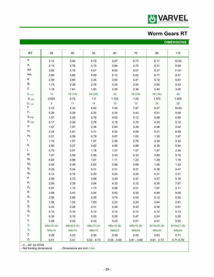
Worm Gears RT
DIMENSIONS
RT 28 40 50 60 70 85 110
A 3.15 3.94 4.72 5.67 6.77 8.11 10.04
A1 2.13 2.76 3.15 3.94 4.72 5.51 6.69
AA 3.82 4.78 5.67 6.85 8.07 9.37 11.61
AA1 2.80 3.60 4.09 5.12 6.02 6.77 8.27
B 2.09 2.80 3.35 3.94 4.41 5.12 5.67
B1 1.73 2.36 2.76 3.35 3.54 3.94 4.53
C 1.18 1.61 1.93 2.36 2.36 2.40 3.05
D (H7) 14 19 (18) 24 (25) 25 28 (30) 32 (35) 42
D (H7) 0.625 0.75 1.0 1.125 1.25 1.375 1.625
D2 (h6) 9 11 14 19 19 24 28
F 3.15 4.33 4.92 7.09 7.87 8.27 10.63
F1 0.28 0.28 0.35 0.35 0.43 0.51 0.59
G (H8) 1.97 2.36 2.76 4.53 5.12 5.98 6.69
G1 (h8) 2.17 2.36 2.76 3.15 3.74 4.33 5.12
H 1.57 1.97 2.36 2.83 3.39 4.06 5.02
H1 2.24 2.81 3.31 4.02 4.69 5.31 6.59
H2 0.51 0.59 0.79 0.87 1.02 1.30 1.67
I 1.10 1.57 1.97 2.36 2.76 3.35 4.33
K 2.60 3.27 3.82 4.06 4.96 6.30 5.94
L 0.79 0.91 1.18 1.57 1.57 1.97 2.36
M 1.97 2.56 2.95 3.43 4.33 4.86 5.75
M1 0.64 0.86 1.07 1.11 1.23 1.39 1.78
M2 0.40 0.49 0.63 0.89 0.89 1.06 1.22
N1 0.20 0.24 0.31 0.31 0.31 0.39 0.47
N2 0.12 0.16 0.20 0.24 0.24 0.31 0.31
P 2.09 2.72 3.66 3.39 4.37 4.37 5.16
P1 2.95 3.39 3.94 4.33 5.12 6.30 7.87
P2 0.91 1.10 1.73 0.98 2.01 1.97 2.11
R 2.68 3.43 3.54 5.93 6.50 6.89 9.06
R1 2.56 2.95 3.35 3.74 4.53 5.12 6.50
S 1.08 1.52 1.83 2.24 2.24 2.64 2.91
S1 0.24 0.28 0.31 0.39 0.43 0.55 0.51
S2 0.10 0.10 0.12 0.12 0.12 0.12 0.14
U 0.39 0.16 0.20 0.26 0.47 0.24 0.20
V 0.28 0.35 0.43 0.43 0.51 0.51 0.55
V1 M6x10 (4) M6x8.5 (4) M8x10 (4) M8x16 (8) M8x16 (8) M10x18 (8) M10x21 (8)
V2 M4x10 M4x10 M6x15 M8x20 M8x20 M8x20 M8x20
Z 0.28 0.23 0.39 0.39 0.55 0.63 0.71
Z2 0.51 0.51 0.52 - 0.73 0.55 - 0.59 0.61 - 0.69 0.61 - 0.73 0.71-0.79
- V1 - 90° for RT28 - Not binding dimensions - Dimensions are inch / mm

- 30 -
Helical Worm Gears TA
DIMENSIONS
F RT
B3

- 31 -
Helical Worm Gears TA
DIMENSIONS
63 71 80 100 TA
40 50 60 50 60 70 85 60 70 85 110 110
A 3.94 4.72 5.67 4.72 5.67 6.77 8.11 5.67 6.77 8.11 10.04 10.04
A1 2.76 3.15 3.94 3.15 3.94 4.72 5.51 3.94 4.72 5.51 6.69 6.69
AA 4.78 5.67 6.85 5.67 6.85 8.07 9.37 6.85 8.07 9.37 11.61 11.61
AA1 3.60 4.09 5.12 4.09 5.12 6.02 6.77 5.12 6.02 6.77 8.27 8.27
B 2.80 3.35 3.94 3.35 3.94 4.41 5.12 3.94 4.41 5.12 5.67 5.67
B1 2.36 2.76 3.35 2.76 3.35 3.54 3.94 3.35 3.54 3.94 4.53 4.53
C 1.61 1.93 2.36 1.93 2.36 2.36 2.40 2.36 2.36 2.40 3.05 3.05
D(H7) 19 (18) 24 (25) 25 24 (25) 25 28 (30) 32 (35) 25 28 (30) 32 (35) 42 42
D(H7) 0.75 1.0 1.125 1.0 1.125 1.25 1.375 1.125 1.25 1.375 1.625 1.625
D2 (h6) 11 11 11 14 14 14 14 19 19 19 19 24
F 4.33 4.92 7.09 4.92 7.09 7.87 8.27 7.09 7.87 8.27 10.63 10.63
F1 0.28 0.35 0.35 0.35 0.35 0.43 0.51 0.35 0.43 0.51 0.59 0.59
G (H8) 2.36 2.76 4.53 2.76 4.53 5.12 5.98 4.53 5.12 5.98 6.69 6.69
G1 (h8) 2.36 2.76 3.15 2.76 3.15 3.74 4.33 3.15 3.74 4.33 5.12 5.12
H 1.97 2.36 2.83 2.36 2.83 3.39 4.06 2.83 3.39 4.06 5.02 5.02
H1 2.81 3.31 4.02 3.31 4.02 4.69 5.31 4.02 4.69 5.31 6.59 6.59
H2 0.59 0.79 0.87 0.79 0.87 1.02 1.30 0.87 1.02 1.30 1.67 1.67
I 1.57 1.97 2.36 1.97 2.36 2.76 3.35 2.36 2.76 3.35 4.33 4.33
I1 1.26 1.26 1.26 1.57 1.57 1.57 1.57 1.97 1.97 1.97 1.97 1.97
K 6.04 6.73 6.97 6.81 7.20 8.23 8.82 8.15 9.15 9.86 10.41 12.91
L 0.91 0.91 0.91 1.18 1.18 1.18 1.18 1.57 1.57 1.57 1.57 1.97
M1 0.86 1.07 1.11 1.07 1.11 1.23 1.39 1.11 1.23 1.39 1.78 1.78
M2 0.49 0.49 0.49 0.63 0.63 0.63 0.63 0.89 0.89 0.89 0.89 1.06
N1 0.24 0.31 0.31 0.31 0.31 0.31 0.39 0.31 0.31 0.39 0.47 0.47
N2 0.16 0.16 0.16 0.20 0.20 0.20 0.20 0.24 0.24 0.24 0.24 0.31
P 2.72 3.66 3.39 3.66 3.39 4.37 4.37 3.39 4.37 4.37 5.16 5.16
P1 3.39 3.94 4.33 3.94 4.33 5.12 6.30 4.33 5.12 6.30 7.87 7.87
P2 1.10 1.73 0.98 1.73 0.98 2.01 1.97 0.98 2.01 1.97 2.11 2.11
R 3.43 3.54 5.93 3.54 5.93 6.50 6.89 5.93 6.50 6.89 9.06 9.06
R1 2.95 3.35 3.74 3.35 3.74 4.53 5.12 3.74 4.53 5.12 6.50 6.50
S 1.52 1.83 2.24 1.83 2.24 2.24 2.64 2.24 2.24 2.64 2.91 2.91
S1 0.28 0.31 0.39 0.31 0.39 0.43 0.55 0.39 0.43 0.55 0.51 0.51
S2 0.10 0.12 0.12 0.12 0.12 0.12 0.12 0.12 0.12 0.12 0.14 0.14
U 0.16 0.20 0.26 0.20 0.26 0.47 0.24 0.26 0.47 0.24 0.20 0.20
V 0.35 0.43 0.43 0.43 0.43 0.51 0.51 0.43 0.51 0.51 0.55 0.55
V1 M6x8 (4) M8x10 (4) M8x16 (8) M8x10 (4) M8x16 (8) M8x16 (8) M10x18 (8) M8x16 (8) M8x16 (8) M10x18 (8) M10x21 (8) M10x21 (8)
V3 M4 x 10 M4 x 10 M4 x 10 M6 x 15 M6 x 15 M6 x 15 M6 x 15 M8 x 20 M8 x 20 M8 x 20 M8 x 20 M8 x 20
Y1 4.13 4.13 4.13 4.72 4.72 4.72 4.72 5.51 5.51 5.51 5.51 5.51
Z 0.24 0.39 0.39 0.39 0.39 0.55 0.63 0.39 0.55 0.63 0.71 0.71
Z2 0.51 0.51 0.51 0.51 0.51 0.51 0.51 0.55 0.55 0.55 0.55 0.55
- V1 - 90° for RT28 - Not binding dimensions - Dimensions are inch / mm

- 32 -
Double Worm Gears RT
DIMENSIONS
F RT/RT
B3

- 33 -
Double Worm Gears RT
DIMENSIONS
28 40 50 RT/RT
28 40 50 60 70 85 110
A 3.15 3.94 4.72 5.67 6.77 8.11 10.04
A1 2.13 2.76 3.15 3.94 4.72 5.51 6.69
AA 3.82 4.78 5.67 6.85 8.07 9.37 11.61
AA1 2.80 3.60 4.09 5.12 6.02 6.77 8.27
B 2.09 2.80 3.35 3.94 4.41 5.12 5.67
B1 1.73 2.36 2.76 3.35 3.54 3.94 4.53
C 1.18 1.61 1.93 2.36 2.36 2.40 3.05
D (H7) 14 19 (18) 24 (25) 25 28 (30) 32 (35) 42
D (H7) 0.625 0.75 1.0 1.125 1.25 1.375 1.625
D2 (h6) 9 9 9 9 11 11 14
F 3.15 4.33 4.92 7.09 7.87 8.27 10.63
F1 0.28 0.28 0.35 0.35 0.43 0.51 0.59
G (H8) 1.97 2.36 2.76 4.53 5.12 5.98 6.69
G1 (h8) 2.17 2.36 2.76 3.15 3.74 4.33 5.12
H 1.57 1.97 2.36 2.83 3.39 4.06 5.02
H1 2.24 2.81 3.31 4.02 4.69 5.31 6.59
H2 0.51 0.59 0.79 0.87 1.02 1.30 1.67
H3 1.57 1.57 1.57 1.57 1.97 1.97 2.36
I 1.10 1.57 1.97 2.36 2.76 3.35 4.33
I1 1.10 1.10 1.10 1.10 1.57 1.57 1.97
K 3.13 3.92 5.55 5.73 5.65 7.83 7.99
K1 2.26 2.26 2.26 2.26 2.78 2.78 3.27
L 0.79 0.79 0.79 0.79 0.91 0.91 1.18
M 1.97 1.97 1.97 1.97 2.56 2.56 2.95
M1 0.64 0.86 1.07 1.11 1.23 1.39 1.78
M2 0.40 0.40 0.40 0.40 0.49 0.49 0.63
N1 0.20 0.24 0.31 0.31 0.31 0.39 0.47
N2 0.12 0.12 0.12 0.12 0.16 0.16 0.20
P 2.09 2.72 3.66 3.39 4.37 4.37 5.16
P1 2.95 3.39 3.94 4.33 5.12 6.30 7.87
P2 0.91 1.10 1.73 0.98 2.01 1.97 2.11
R 2.68 3.43 3.54 5.93 6.50 6.89 9.06
R1 2.56 2.95 3.35 3.74 4.53 5.12 6.50
S 1.08 1.52 1.83 2.24 2.24 2.64 2.91
S1 0.24 0.28 0.31 0.39 0.43 0.55 0.51
S2 0.10 0.10 0.12 0.12 0.12 0.12 0.14
S3 1.18 1.18 1.18 1.18 1.61 1.61 1.93
U 0.39 0.16 0.20 0.26 0.47 0.24 0.20
V 0.28 0.35 0.43 0.43 0.51 0.51 0.55
V1 M6x10 (4) M6x8,5 (4) M8x10 (4) M8x16 (8) M8x16 (8) M10x18 (8) M10x21 (8)
V2 M4x10 M4x10 M4x10 M4x10 M4x10 M4x10 M6x15
Y1 3.15 3.54 3.54 3.54 4.72 4.72 4.72
Z 0.28 0.24 0.39 0.39 0.55 0.63 0.71
- V1 - 90° for RT28 - Not binding dimensions - Dimensions are inch / mm
- 34 -
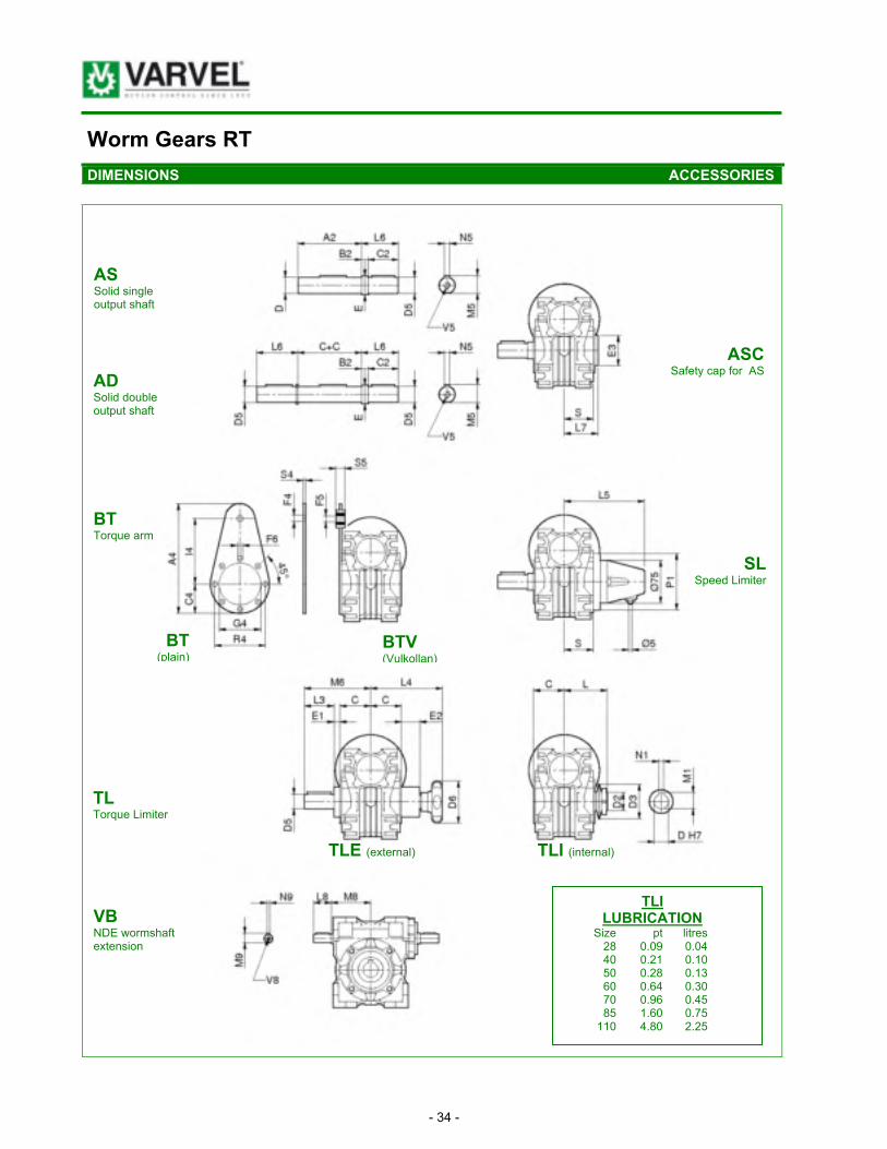
Worm Gears RT
DIMENSIONS ACCESSORIES
AS Solid single output shaft
AD Solid double output shaft
BT Torque arm
TL Torque Limiter
ASC
Safety cap for AS
SL Speed Limiter
BT
(plain) BTV (Vulkollan)
VB NDE wormshaft extension
TLI LUBRICATION
Size pt litres 28 0.09 0.04 40 0.21 0.10 50 0.28 0.13 60 0.64 0.30 70 0.96 0.45 85 1.60 0.75 110 4.80 2.25
TLE (external) TLI (internal)

- 35 -
Worm Gears RT
ACCESSORIES DIMENSIONS
RT 28 40 50 60 70 85 110
AS & A2 2.28 3.15 3.74 4.61 4.61 4.69 6.02
AD B2 0.04 0.39 0.39 0.39 0.39 0.39 0.39
C 1.18 1.61 1.93 2.36 2.36 2.40 3.05
C2 1.18 1.57 1.77 1.97 2.36 2.76 4.33
D5 (g6) 0.625 (14) 0.75 (19) 1.0 (24) 1.125 (25) 1.25 (28) 1.375 (32) 1.625 (42)
E 0.55 0.87 1.10 1.18 1.34 1.50 1.97
L6 1.22 1.97 2.17 2.36 2.76 3.15 4.33
M5 0.63 0.85 1.06 1.10 1.22 1.38 1.77
N5 0.20 0.24 0.31 0.31 0.31 0.39 0.47
V5 M5x10 M8x20 M8x20 M8x20 M8x20 M10x25 M10x25
ASC E3 1.97 2.05 2.44 2.95 3.54 3.94 4.72
L7 1.42 1.91 2.19 2.70 2.64 3.03 3.35
S 1.08 1.52 1.83 2.24 2.24 2.64 2.91
BT & A4 5.43 6.61 7.28 9.25 11.61 12.32 15.28
BTV C4 1.50 1.69 2.36 2.17 2.56 2.95 3.94
F4 0.41 0.41 0.41 0.41 0.41 0.81 0.81
F5 0.39 0.39 0.39 0.39 0.39 0.79 0.79
F6 0.28 0.28 0.35 0.35 0.35 0.47 0.51
G4 2.17 2.36 2.76 3.15 3.74 4.33 5.12
I4 3.15 3.94 3.94 5.91 7.87 7.87 9.84
R4 2.56 2.95 3.35 3.74 4.53 5.12 6.50
S4 0.16 0.16 0.16 0.24 0.24 0.24 0.24
S5 0.59 0.59 0.59 0.79 0.79 0.98 0.98
SL L5 3.78 4.45 4.84 5.24 5.24 5.47 5.91
P1 3.07 3.54 3.94 4.33 5.12 6.30 7.87
S 1.08 1.52 1.83 2.24 2.24 2.64 2.91
TLE D6 2.05 2.76 2.76 2.76 3.15 3.94 3.94
E1 0.39 0.47 0.47 0.59 0.55 0.75 0.94
E2 1.10 1.46 1.22 1.57 1.81 2.24 2.80
L3 1.18 1.57 1.97 1.97 2.36 2.76 3.15
L4 3.70 4.57 4.65 5.04 5.75 6.61 7.91
M6 2.76 3.66 4.37 4.92 5.28 5.91 7.13
TLI D(H7) [mm] 14 18 24 25 28 32 42
D2 1.57 2.20 2.80 2.80 3.15 3.54 4.92
D3 0.56x0.79 0.77x0.81 0.96x1.10 1.00x1.02 1.12x0.87 1.28x1.06 1.67x1.52
L 1.77 2.42 3.03 3.41 3.50 3.70 4.29
M1 0.61* 0.86 1.07 1.07* 1.23 1.39 1.78
N1 (H9) 0.20 0.24 0.31 0.31 0.31 0.39 0.47
VB D9 [mm] 9 11 14 19 19 24 28
L8 0.79 0.91 1.18 1.57 1.57 1.97 2.36
M8 1.69 2.17 2.56 3.03 3.31 4.19 5.71
M9 0.40 0.49 0.63 0.89 0.89 1.06 1.22
N9 0.12 0.16 0.20 0.24 0.24 0.31 0.31
V8 M4x10 M4x10 M6x15 M8x20 M8x20 M8x20 M8x20
D5 (,,) = Diameter on demand - Dimensions are inch / mm

- 36 -
Worm Gears RS-RT
DIMENSIONS AND WEIGHTS HELICAL SINGLE-STAGE ATTACHMENT - XA
XA D h7
[mm] G I J h8 L O Q U U1 T V W Z
63 14 4.13 1.26 2.76 1.18 3.35 3.27 0.26 M6 0.10 0.28 1.28 M5x10
71 19 4.72 1.57 3.15 1.57 3.94 3.54 0.22 M6 0.10 0.30 1.67 M8x20
80 24 5.51 1.97 3.74 1.95 4.53 4.49 0.35 M6 0.10 0.41 2.05 M8x20
100 28 7.87 2.48 5.12 2.26 6.50 6.97 0.41 0.41 0.10 0.47 2.36 M10 x 22
XA
lb
pt
litres
63 2.23 0.09 0.04
71 4.28 0.13 0.06
80 6.36 0.21 0.10
100 15.25 0.42 0.20
Dimensions are inch / mm

- 37 -
Worm Gears RT
BACK-DRIVING AND SELF-LOCKING
When back-driving a worm gear set using the worm wheel as input, the efficiency is lower than forward-driving and, by varying the design data, back-drive efficiency can be reduced to zero obtaining a self-locking, or irreversible, gear set.
When back-driving the worm gear, internal friction tends to lock the mesh, and the bigger the applied torque is, the more mesh friction increases proportionally augmenting the lockage at the same time.
The most obvious example is during braking or slowing-down where the inertial load will try to back-drive the worm shaft.
A worm gear is intended as a self-locking drive when the lead angle (!) is lower than the friction angle (arc tangent of friction coeffi-
cient).
Tooth contact is dynamic even when the mesh velocity is zero, as vibrations in a non-rotating gear set can induce motion in the tooth contact.
To provide a safety factor, a lead angle smaller than 3 degrees is recommended for full self-locking condition, and a lead angle bigger than 10 degrees for full revrsibility condition, according to the table of relations between lead angles and self-locking.
Lead angle Static self-locking / Reversibility
! > 20° Full reversibility
10° < ! < 20° High reversibility
5° < ! < 10°
Good reversibility
Poorstatic self-locking
3° < ! < 5°
Poor reversibility
Good static self-locking
1° < ! < 3° Full static self-locking
LEAD ANGLE DATA
Series RT Ratio 5 7 10 15 20 28 40 49 56 70 80 100
28 ! - - - 23°11’ 16°41’ 11°18’ 10°23’ 6°06’ 5°14’ 4°19’ 3°03’ 2°27’ 2°37’ 2°20’
40 ! 30°57’ 21°36’ 16°41’ 11°18’ 8°31’ 5°39’ 4°17’ 3°48’ 3°25’ 3°01’ 2°51’ 2°38’
50 ! 30°57’ 23°52’ 16°41’ 11°18’ 8°59’ 6°19’ 4°31’ 4°14’ 3°42’ 2°44’ 2°51’ 2°17’
60 ! 36°32’ 25°33’ 19°0’ 12°55’ 11°18’ 6°49’ 5°42’ 5°11’ 3°55’ 3°38’ 2°51’ 2°51’
70 ! 34°01’ 26°51’ 18°38’ 12°40’ 11°18’ 7°12’ 5°42’ 4°48’ 4°05’ 3°16’ 2°51’ 2°38’
85 ! 34°47’ 26°05’ 19°09’ 13°02’ 11°18’ 6°58’ 5°52’ 4°52’ 4°45’ 3°48’ 3°14’ 2°40’
110 ! - - - 26°22’ 20°43’ 14°09’ 11°18’ 7°04’ 5°42’ 4°43’ 4°29’ 3°54’ 3°39’ 2°34’
130 ! - - - 26°57’ 21°20’ 14°06’ 13°05’ 7°14’ 6°18’ 5°18’ 6°20’ 4°33’ 3°30’ 3°40’
150 ! - - - 25°33’ 21°48’ 16°22’ 13°24’ 7°35’ 7°07’ 5°48’ 6°11’ 4°17’ 3°45’ 3°43’

- 38 -
Worm Gears RS-RT
INPUT ARRANGEMENT & DIRECTION OF ROTATION
FRS/FRT 28 40 50 60 70 85 110 130 150
NEMA 42 G3 G3
NEMA48 G3
NEMA56 G3 G5 G5 G6 G6 G6
NEMA140 G5 G6 G6 G6 (G8) (G8)
NEMA180 G6 G6 G6 (G8) (G8)
NEMA210 (G8)
IEC90 G6 ! !
IEC100/112 G6 ! !
IEC132 ! ! !
IEC160 !
G3, G5, G6 = Existing elastic coupling 'G' input (G8) = In progress ! = IEC quill input
FRA/FTA IEC56 IEC63 IEC71 IEC80 IEC90 IEC100
SXA63 ! !
SXA71 !
SXA80 ! !
SXA100 G6 G6 G6 G6
Wormshaft upwards Rotation Wormshaft downwards
RS RT
RA TA
RS / RS RT / RT

- 39 -
Worm Gears RS-RT
OUTPUT SHAFTS & CONVERSION FACTORS
RS-RT 28 40 50 60 70 85 110 130 150
A2 2.28 3.16 3.74 4.61 4.61 4.69 6.02 6.97 8.15
C + C 2.36 3.22 3.86 4.72 4.72 4.80 6.10 7.08 8.26
C2 1.375 1.57 1.97 2.36 2.36 2.76 3.15 3.54 3.94
D H7 0.55 / 14 0.75 / 19 0.94 / 24 0.98 / 25 8.98 / 28 1.26 / 32 1.65 / 42 1.89 / 48 2.17 / 55
D5 g6 0.625 0.75 1.0 1.125 1.25 1.375 1.625 1.75 2.0
E 0.55 0.87 1.1 1.18 1.34 1.50 1.97 2.28 2.48
L6 1.417 1.97 2.37 2.76 2.76 3.15 3.54 4.33 4.73
M1 0.64 0.86 1.07 1.11 1.23 1.39 1.82 2.04 2.33
M5 0.52 0.66 0.86 0.99 1.11 1.20 1.42 1.54 2.28
N1 0.20 0.24 0.31 0.31 0.31 0.39 0.47 0.55 0.63
N5 x N5 3/16
3/16
1/4
1/4
1/4
5/16
8/8
8/8
1/2
Key length 1 1/16 1
1/16 1
5/16 1
11/16 1
11/16 1
13/16 2
1/4 2
1/4 2
5/8
Dimensions are inch / mm
Imperial Conversions Metric
1 lb = 4.45 N Mass & Force 1 N = 0.225 lb 1 lb = 0.454 kg 1 kg = 2.205 lb 1 oz = 0.028 kg 1 kg = 35.27 oz
HP (60Hz) = kW (50Hz) x 1.341 x 1.2 Power kW (50Hz) = HP (60Hz) x 0.745 x 0.833 HP (50Hz) = kW (50Hz) x 1.341 kW (50Hz) = HP (50Hz) x 0.745 HP = in-lb x RPM : (113,350 x eff.) kW = Nm x RPM : (9550 x eff.)
1 in-lb = 0.113 Nm Torque 1 Nm = 8.851 in-lb 1 ft-lb = 1.355 Nm 1 Nm = 0.738 ft-lb ft-lb = 9445 x HP x eff. : RPM Nm = 9550 x kW x eff. : RPM in-lb =113,350 x HP x eff. : RPM
1 pt (US) = 0.47 litre Volume 1 litre = 2.13 pt (US)
MRS-MRT NA 270508.doc

Other Products & Services
!"#$"%&'"()"%*%#+&,%-&.%/$%**0$%/&1*02$3*+
180 Covington Drive, Bloomingdale, Illinois USA 60108-3105Phone: 630-980-1133 Fax: 630-980-1232Email: [email protected]: www.diequa.com
2011/PDF
Planetary Gearheads
ManufacturingDieQua Corporation’s manu-facturing capabilities allow production of many of our drive components, options, and dimension modifications. Com-plete specials are also available.
Engineering SupportDieQua Corporation has several decades of combined experience specifying motion control components. This as-sures the proper selection for your unique requirements.
AssemblyDieQua Corporation has a team of factory trained technicians that assemble the majority of the drives we provide. This allows prompt delivery of your produc-tion or service requirements.
WarehousingDieQua maintains an extensive inventory of common gear-heads, bushings, and servo motor adapter plates for quick delivery of small orders, proto-types and spare parts.
Manufacturing Partners
Spiral Bevel Gearboxes
Variable Speed Drives
Speed Correction Drives
Helical Gearmotors andSpeed Reducers
Servo Worm Reducers
Screw Jacks