wormald international return to table of …halon.org/pdfs/wormald.pdfreturn to table of contents...
TRANSCRIPT

Return to Table of Contents
WORMALD INTERNATIONALELECTRIC VALVE ACTUATOR
SA. ANSUL N.V.
PART OF WORMRLD
INTERNATIONAL GROUP
ELECTRIC VALVE ACTUATOR EVA MFG DATA SHEET: T46
DATE:09/86 RE:PAGE:
SCOPE:
The EVA actuator has been specially designed to be mounted on all the ANSUL Halon and european carbon dioxyde valves of the latest generation by means of a swivel nut. The coupling allows ease of connection, positioning and removal for testing or servicing.
This electric actuator may be used in combination with the multiple stock actuator (p/n 303444) offering pneumatic and manual actuation as well.
The actuator develops a very high actuation force, giving the possibility to operate either the halon valves types 360 psi US bar) and 600 psi (41,5bar) either the CO2 MA valves, from -20 degrees C up to +50 degrees C.
The connection and the disconnection of the plug-in connector provide the facility to remove the electric cable before disassembling the actuator from the valve. This is an appreciable advantage for inspection or arming in case of functional test and/or trouble shooting of the release circuit.
The connector is provided with & voltage peak suppression diode.
All materials in contact with the surrounding are in brass and zincolated bichromatod steel to provide a good corrosion resistance.
303426 Electric valve actuator - packed (fig 1) (with connector)
303445 Arming tool (fig 2)

SEPARATE COMPONENTS
Fig No 1 Part No Description
--
1
2
303426
--
801216
Electric valve actuator EVA - packed
303426 without connector
Connector
Fig No 2 Part No Description
- 303445 Arming tool - packed
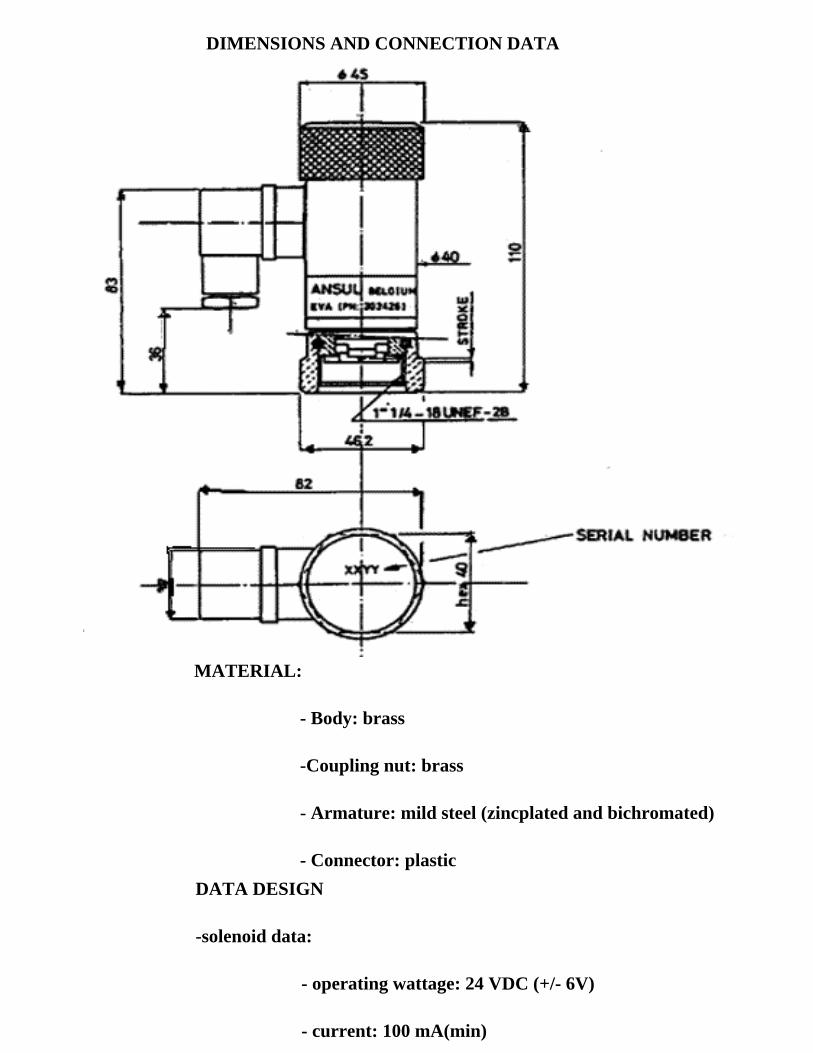
MATERIAL:
- Body: brass
-Coupling nut: brass
- Armature: mild steel (zincplated and bichromated)
- Connector: plastic
DATA DESIGN
-solenoid data:
- operating wattage: 24 VDC (+/- 6V)
- current: 100 mA(min)
DIMENSIONS AND CONNECTION DATA
- resistance: 180 Ohm (135 mA at nominal 24 VDC)
- temperature range:
- installed: -20 degrees C to +50 degrees C
- stored -30 degrees C to +75 degrees C
- functional data:
- potential energy stared: 2 joules
- minimum pull-in wattage: 18 VDC
- minimum drop out voltage after release, the spring pushes permanently on the piston with sufficient force to maintain the schrader valve open
- min. voltage application time : 1 sec.
- max. recommended voltage application time: 1 min. (e.g. during tests)
- plug-in connection date:
- cable gland : PG 11
- terminals: capability : 1, 5mm2 flexible wire
- terminate: 3 plugs No 1 = positive
No 2= negative
= earth
- projection: by suppression diode 1N4007
- tightening grade: IP65
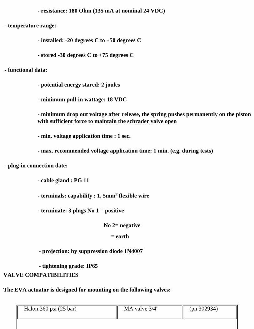
VALVE COMPATIBILITIES
The EVA actuator is designed for mounting on the following valves:
Halon:360 psi (25 bar) MA valve 3/4" (pn 302934)

MA valve 3/4" (pn 302936)
Valve 1" (pn 302797)
Valve 2" (pn 302796)
600 psi (41,5 bar) Valve 1" (pn 302817)
CO2 MA valve 3/4" (pn 302935)
MA valve 3/4" (pn 302937)
ARMING OF THE ACTUATOR
To arm the EVA actuator. the arming tool pn 303445 is needed. Arming is a very simple operation, one must put the actuator on the arming block and by an action of both hands on the top of the actuator, it will be armed. An arming forces between 20 kg and 25 kg is required.
SHIPPING DATA
- electric valve actuator:
Part No 303426 (packed in carton box)
Box dimensions : 130 x 90 x 55.
Shipping weight : 0.9 kg
- arming tool:
Part No 30344S (packed in carton box)
Box dimensions : 95 x 90 x 70
Shipping weight: 0.5 kg
WORMALD INTERNATIONAL1 " NGT HALON 1301 VALVE
SA. ANSUL N.V.
PART OF WORMRLD
INTERNATIONAL GROUP
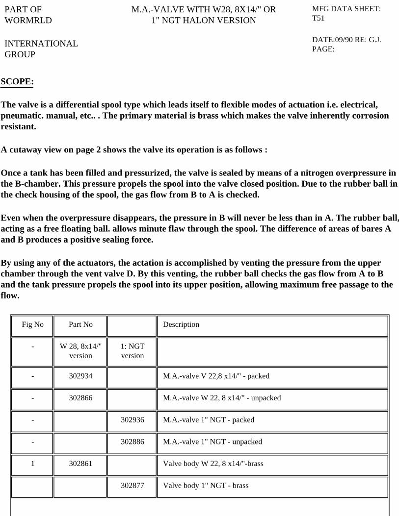
M.A.-VALVE WITH W28, 8X14/" OR1" NGT HALON VERSION
MFG DATA SHEET: T51
DATE:09/90 RE: G.J. PAGE:
SCOPE:
The valve is a differential spool type which leads itself to flexible modes of actuation i.e. electrical, pneumatic. manual, etc.. . The primary material is brass which makes the valve inherently corrosion resistant.
A cutaway view on page 2 shows the valve its operation is as follows :
Once a tank has been filled and pressurized, the valve is sealed by means of a nitrogen overpressure in the B-chamber. This pressure propels the spool into the valve closed position. Due to the rubber ball in the check housing of the spool, the gas flow from B to A is checked.
Even when the overpressure disappears, the pressure in B will never be less than in A. The rubber ball, acting as a free floating ball. allows minute flaw through the spool. The difference of areas of bares A and B produces a positive sealing force.
By using any of the actuators, the actation is accomplished by venting the pressure from the upper chamber through the vent valve D. By this venting, the rubber ball checks the gas flow from A to B and the tank pressure propels the spool into its upper position, allowing maximum free passage to the flow.
Fig No Part No Description
- W 28, 8x14/" version
1: NGT version
- 302934 M.A.-valve V 22,8 x14/" - packed
- 302866 M.A.-valve W 22, 8 x14/" - unpacked
- 302936 M.A.-valve 1" NGT - packed
- 302886 M.A.-valve 1" NGT - unpacked
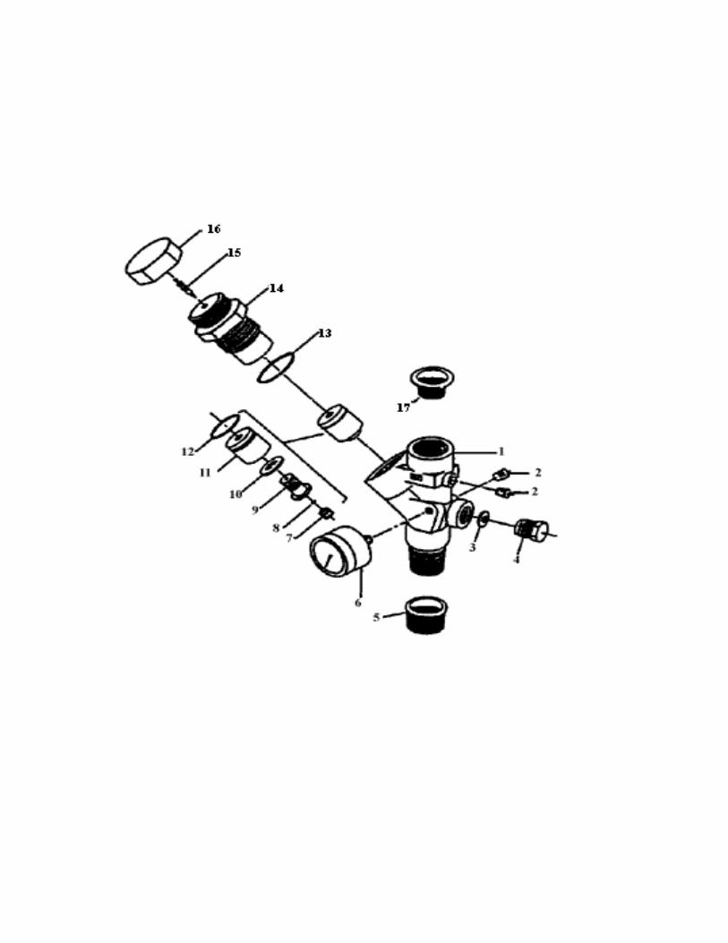
1 302861 Valve body W 22, 8 x14/"-brass
302877 Valve body 1" NGT - brass
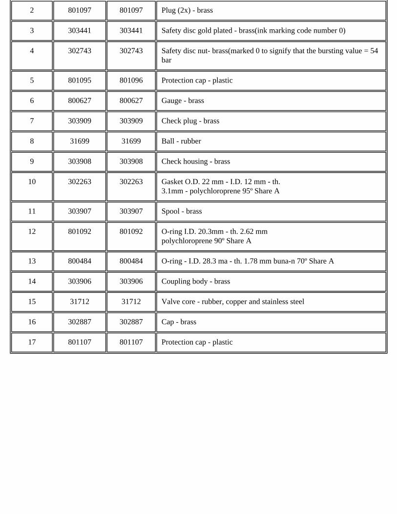
2 801097 801097 Plug (2x) - brass
3 303441 303441 Safety disc gold plated - brass(ink marking code number 0)
4 302743 302743 Safety disc nut- brass(marked 0 to signify that the bursting value = 54 bar
5 801095 801096 Protection cap - plastic
6 800627 800627 Gauge - brass
7 303909 303909 Check plug - brass
8 31699 31699 Ball - rubber
9 303908 303908 Check housing - brass
10 302263 302263 Gasket O.D. 22 mm - I.D. 12 mm - th. 3.1mm - polychloroprene 95º Share A
11 303907 303907 Spool - brass
12 801092 801092 O-ring I.D. 20.3mm - th. 2.62 mmpolychloroprene 90º Share A
13 800484 800484 O-ring - I.D. 28.3 ma - th. 1.78 mm buna-n 70º Share A
14 303906 303906 Coupling body - brass
15 31712 31712 Valve core - rubber, copper and stainless steel
16 302887 302887 Cap - brass
17 801107 801107 Protection cap - plastic

DESIGN DATE:
- Gas: Halon 1301 + Nitrogen
- Working pressure: 25 bar at 21ºC, in a 360 psi Halon 1301 system, when the tanks are filled at a maximum rate of 1,13 kg/L
- Design temperature: -20ºC to +55ºC (-40ºC to +65ºC for shipment only- non pressurized)
-Actuation force an valve care :
theoretical minimum = 30 N Recommended minimum =60 N
DIMENSIONS AND CONNECTION DATA:
- Safety relief device : 54 +/- 3 bar
- Pressure drop : 4 m equivalent length of 3/4" pipe schedule 40
SHIPPING DATE:
W 28,8 : part No :302934 (packed in carton box)
dimensions :height 85 - width 90 - length 140
shipping weight :1,4 kg
1" NGT : part No :302936
dimensions :height 85- width.90 - length 140
shipping weight :1,5 kg
WORMALD INTERNATIONAL MULTIPLE STACK ACTUATOR
SA. ANSUL N.V.
PART OF WORMRLD
INTERNATIONAL GROUP
MULTIPLE STACK ACTUATOR MFG DATA SHEET: T49
DATE:10/86 RE:
SCOPE:
The multiple stack actuator is a very compact actuator to be mounted on the MA Valves or 1" and 2" Halon valves.
This multiple stack actuator differs from the multiple actuator in this way that the EVA electric actuator can be mounted (or stacked) on the top.It can be operated pneumatically or manually whether accessories are added.These accessories are the same as for the multiple actuator and are described in data sheet T48.
A lock pin which look like a big hairpin, is provided to insert during erection, inspection and maintenance, to avoid a spurious activation.
A breakseal for the actuation lever is also provided.
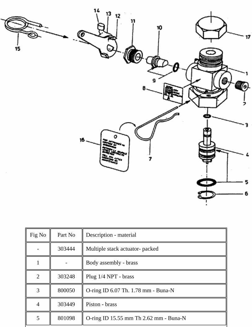
Fig No Part No Description - material
- 303444 Multiple stack actuator- packed
1 - Body assembly - brass
2 303248 Plug 1/4 NPT - brass
3 800050 O-ring ID 6.07 Th. 1.78 mm - Buna-N
4 303449 Piston - brass
5 801098 O-ring ID 15.55 mm Th 2.62 mm - Buna-N
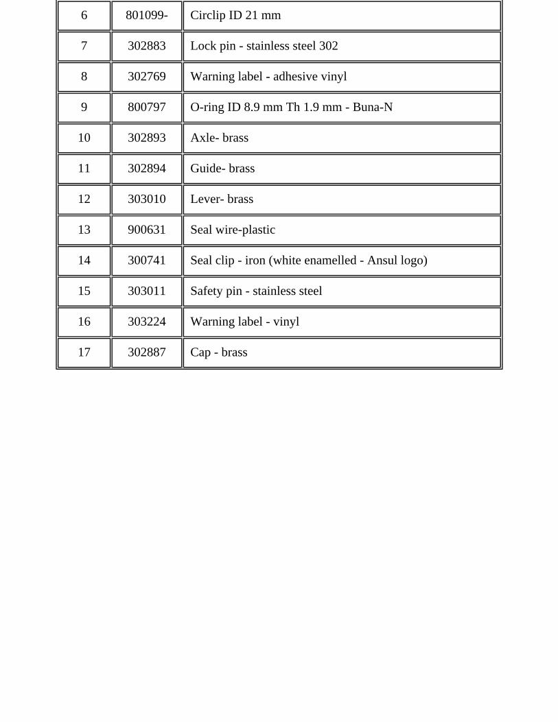
6 801099- Circlip ID 21 mm
7 302883 Lock pin - stainless steel 302
8 302769 Warning label - adhesive vinyl
9 800797 O-ring ID 8.9 mm Th 1.9 mm - Buna-N
10 302893 Axle- brass
11 302894 Guide- brass
12 303010 Lever- brass
13 900631 Seal wire-plastic
14 300741 Seal clip - iron (white enamelled - Ansul logo)
15 303011 Safety pin - stainless steel
16 303224 Warning label - vinyl
17 302887 Cap - brass

DESIGN DATA
Actuation pressure Force on lever
ANSUL valves on Minimum Recommended Min Rec
Halon 360 psig tank at 50º and filled with 1.1 kg/l 1 bar (15 psig) 2 bar (30psig) 7.5M 15 N
Halon 600 psig tank at 50º and filled with 1.13 kg/l 2.75 bar (25 psig) 2.75 bar (40 psig) 13 N 20N
CO2 cylinder at 50º and filled with 0.75 kg/l 3.5 bar (55 psig) 4.5 bar (70 psig) 26N 35N
SHIPPING DATA
Multiple stack actuator:

part No. 303444box dimensions 95 x 90 x 70 mmweight: approx. 700 g
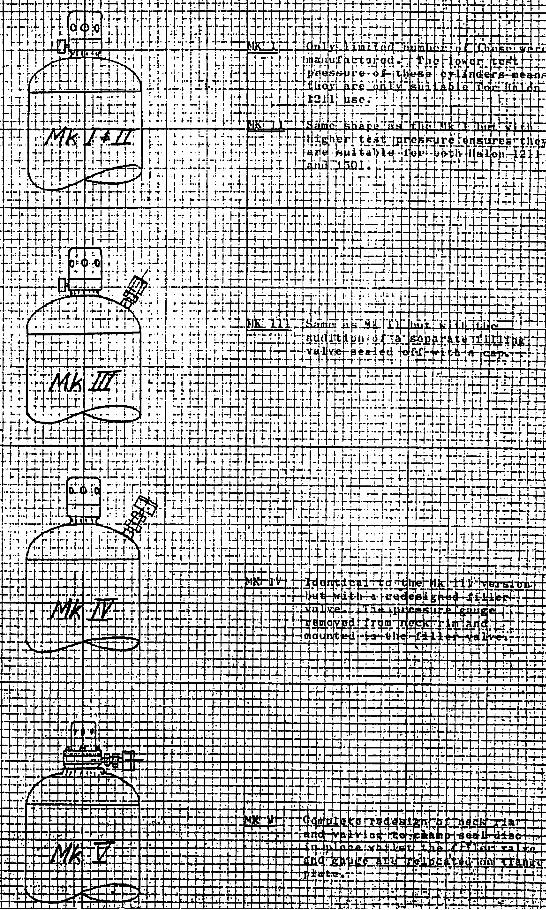
WORMALD INTERNATIONALMK I, II, III, IV, V AND HIGH FLOW
HALON 1301 CONTAINERS
MK I & II PARTS EXPLOSION
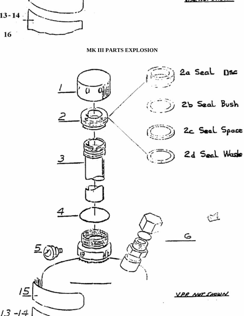
MK III PARTS EXPLOSION

MK IV PARTS EXPLOSION

VALVE AND CYLINDER ASSEMBLIES
The Wormald cylinder and valve assemblies provide the agent, cylinder and valve assembly for both Halon 1301 and 1211 total flooding fire suppression systems They may be used singly or manifolded together to provide the required quantity of agent.
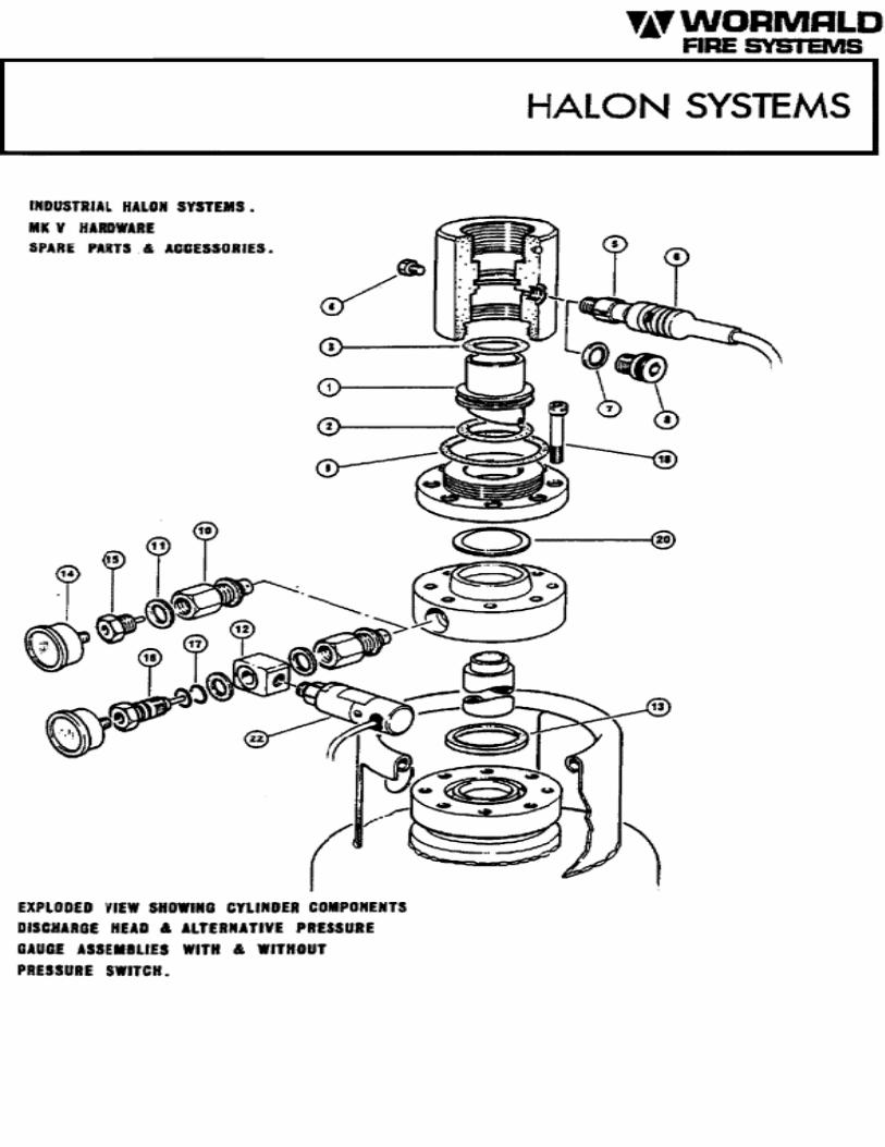
HIGHFLOW VALVES
Wormald Highflow Halon Valves are supplied as an integral part of the Halon cylinder assembly. The 25mm valve is used on the 25 and 48kg capacity cylinders and has a 25mm male NPT threaded pipe outlet. The 50mm valve is used on the 65 and 106kg capacity cylinders and has a 50mm male NPT threaded pipe outlet. The 25mm and 50mm highflow valves am of the differential pressure piston type. They are attached to the cylinder with a 2½- 12UN-2B thread with an O-Ring seal. Valve components are brass, making the valve inherently corrosion resistant. The outlet port and actuation connections are readily accessible for ease of installation and servicing. The valve assembly includes a safety relief device, a pressure gauge, connections for various ancillary equipment and transport caps. A syphon tube is permanently fitted to the valve.
The following actuators are suitable for use with the Highflow Halon Valves and fit to a threaded 1¼" - 18 UNEF-2B connection:
A. Pneumatic (Slave)B. Electrical (24V DC Solenoid)C. Manual-cable pull
D. Manual/PneumaticE. Multi-actuator
Refer to separate actuators data sheet for details.
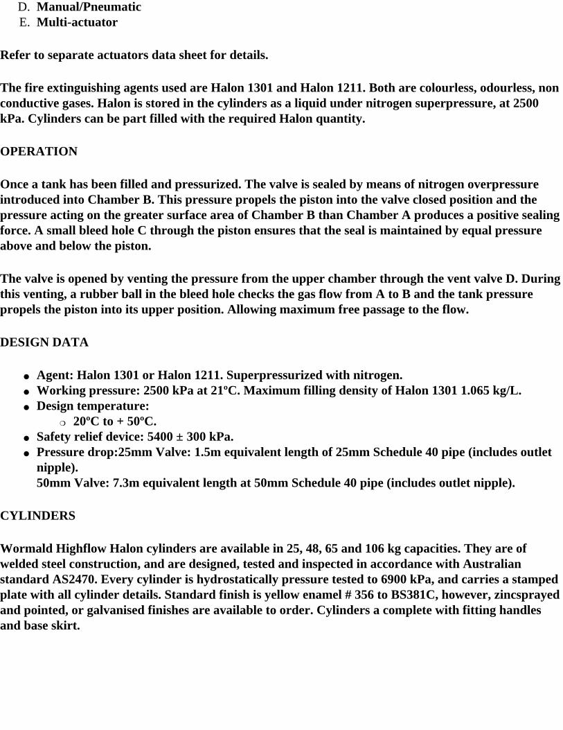
The fire extinguishing agents used are Halon 1301 and Halon 1211. Both are colourless, odourless, non conductive gases. Halon is stored in the cylinders as a liquid under nitrogen superpressure, at 2500 kPa. Cylinders can be part filled with the required Halon quantity.
OPERATION
Once a tank has been filled and pressurized. The valve is sealed by means of nitrogen overpressure introduced into Chamber B. This pressure propels the piston into the valve closed position and the pressure acting on the greater surface area of Chamber B than Chamber A produces a positive sealing force. A small bleed hole C through the piston ensures that the seal is maintained by equal pressure above and below the piston.
The valve is opened by venting the pressure from the upper chamber through the vent valve D. During this venting, a rubber ball in the bleed hole checks the gas flow from A to B and the tank pressure propels the piston into its upper position. Allowing maximum free passage to the flow.
DESIGN DATA
● Agent: Halon 1301 or Halon 1211. Superpressurized with nitrogen.● Working pressure: 2500 kPa at 21ºC. Maximum filling density of Halon 1301 1.065 kg/L.● Design temperature:
❍ 20ºC to + 50ºC.● Safety relief device: 5400 ± 300 kPa.● Pressure drop:25mm Valve: 1.5m equivalent length of 25mm Schedule 40 pipe (includes outlet
nipple).50mm Valve: 7.3m equivalent length at 50mm Schedule 40 pipe (includes outlet nipple).
CYLINDERS
Wormald Highflow Halon cylinders are available in 25, 48, 65 and 106 kg capacities. They are of welded steel construction, and are designed, tested and inspected in accordance with Australian standard AS2470. Every cylinder is hydrostatically pressure tested to 6900 kPa, and carries a stamped plate with all cylinder details. Standard finish is yellow enamel # 356 to BS381C, however, zincsprayed and pointed, or galvanised finishes are available to order. Cylinders a complete with fitting handles and base skirt.
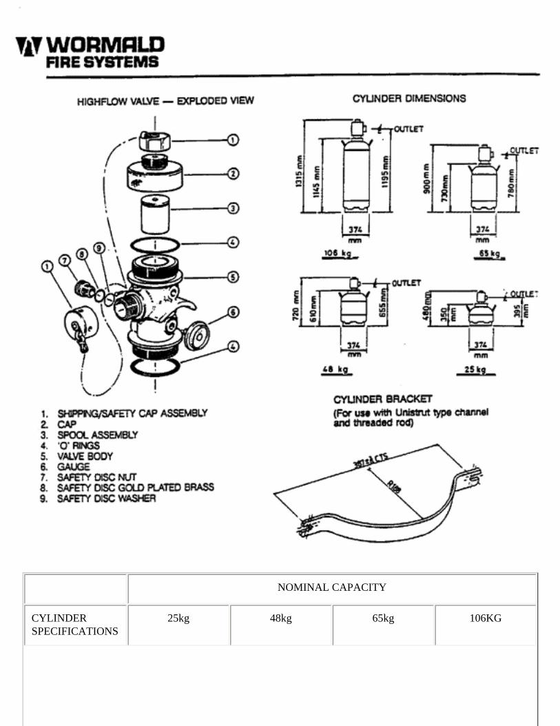
NOMINAL CAPACITY
CYLINDER SPECIFICATIONS
25kg 48kg 65kg 106KG
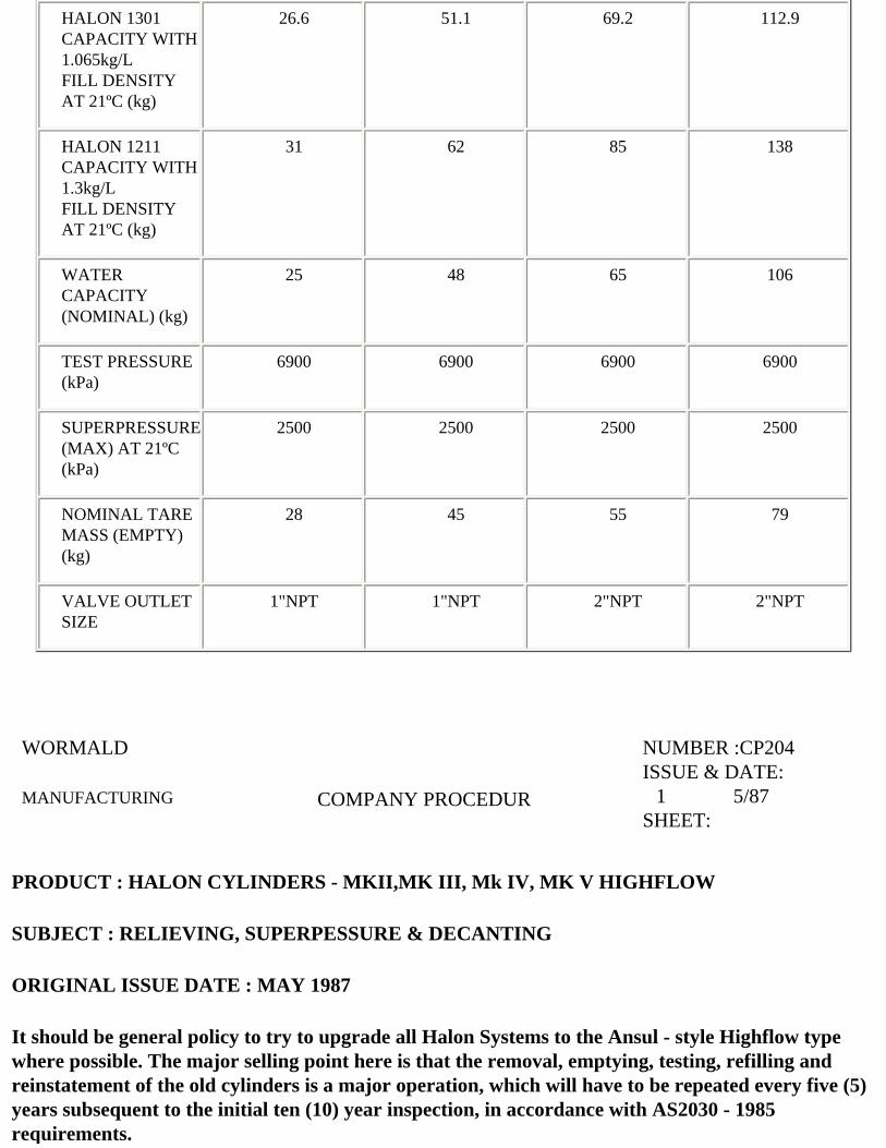
HALON 1301 CAPACITY WITH 1.065kg/LFILL DENSITY AT 21ºC (kg)
26.6 51.1 69.2 112.9
HALON 1211 CAPACITY WITH 1.3kg/L FILL DENSITY AT 21ºC (kg)
31 62 85 138
WATER CAPACITY (NOMINAL) (kg)
25 48 65 106
TEST PRESSURE (kPa)
6900 6900 6900 6900
SUPERPRESSURE (MAX) AT 21ºC (kPa)
2500 2500 2500 2500
NOMINAL TARE MASS (EMPTY) (kg)
28 45 55 79
VALVE OUTLET SIZE
1"NPT 1"NPT 2"NPT 2"NPT
WORMALD
MANUFACTURING
COMPANY PROCEDUR
NUMBER :CP204ISSUE & DATE: --1----------5/87SHEET:
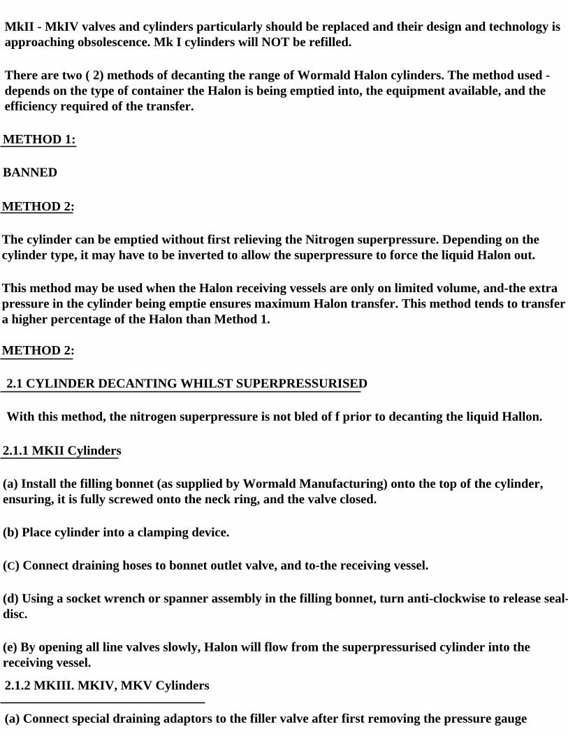
PRODUCT : HALON CYLINDERS - MKII,MK III, Mk IV, MK V HIGHFLOW
SUBJECT : RELIEVING, SUPERPESSURE & DECANTING
ORIGINAL ISSUE DATE : MAY 1987
It should be general policy to try to upgrade all Halon Systems to the Ansul - style Highflow type where possible. The major selling point here is that the removal, emptying, testing, refilling and reinstatement of the old cylinders is a major operation, which will have to be repeated every five (5) years subsequent to the initial ten (10) year inspection, in accordance with AS2030 - 1985 requirements.
MkII - MkIV valves and cylinders particularly should be replaced and their design and technology is approaching obsolescence. Mk I cylinders will NOT be refilled.
There are two ( 2) methods of decanting the range of Wormald Halon cylinders. The method used -depends on the type of container the Halon is being emptied into, the equipment available, and the efficiency required of the transfer.
METHOD 1:
BANNED
METHOD 2:
The cylinder can be emptied without first relieving the Nitrogen superpressure. Depending on the cylinder type, it may have to be inverted to allow the superpressure to force the liquid Halon out.
This method may be used when the Halon receiving vessels are only on limited volume, and-the extra pressure in the cylinder being emptie ensures maximum Halon transfer. This method tends to transfer a higher percentage of the Halon than Method 1.
METHOD 2:
2.1 CYLINDER DECANTING WHILST SUPERPRESSURISED
With this method, the nitrogen superpressure is not bled of f prior to decanting the liquid Hallon.
2.1.1 MKII Cylinders
(a) Install the filling bonnet (as supplied by Wormald Manufacturing) onto the top of the cylinder, ensuring, it is fully screwed onto the neck ring, and the valve closed.
(b) Place cylinder into a clamping device.
(C) Connect draining hoses to bonnet outlet valve, and to-the receiving vessel.
(d) Using a socket wrench or spanner assembly in the filling bonnet, turn anti-clockwise to release seal-disc.
(e) By opening all line valves slowly, Halon will flow from the superpressurised cylinder into the receiving vessel.
2.1.2 MKIII. MKIV, MKV Cylinders
(a) Connect special draining adaptors to the filler valve after first removing the pressure gauge
assembly (MkIV and MkV) or Cap (MkIII). The built-in ball-check valve should prevent excessive leakage until draining adaptor is screwed fully home.
(b) Connect draining hoses and valve to draining adaptor and to the receiving vessel.
(c) Carefully invert cylinder, and clamp securely.
(d) By opening all line valves slowly, Halon will flow from the superpressurised cylinder into the receiving vessel.
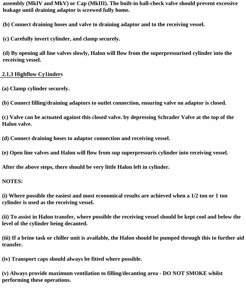
2.1.3 Highflow Cy1inders
(a) Clamp cylinder securely.
(b) Connect filling/draining adaptors to outlet connection, ensuring valve on adaptor is closed.
(c) Valve can be actuated against this closed valve. by depressing Schrader Valve at the top of the Halon valve.
(d) Connect draining hoses to adaptor connection and receiving vessel.
(e) Open line valves and Halon will flow from sup superpressuris cylinder into receiving vessel.
After the above steps, there should be very little Halon left in cylinder.
NOTES:
(i) Where possible the easiest and most economical results are achieved when a 1/2 ton or 1 ton cylinder is used as the receiving vessel.
(ii) To assist in Halon transfer, where possible the receiving vessel should be kept cool and below the level of the cylinder being decanted.
(iii) If a brine task or chiller unit is available, the Halon should be pumped through this to further aid transfer.
(iv) Transport caps should always be fitted where possible.
(v) Always provide maximum ventilation to filling/decanting area - DO NOT SMOKE whilst performing these operations.
Return to Table of Contents